

Page 1

User's Manual
Version 6.6
January 2014
Document # LTRT-65422
MediaPack™ Series
MP-11x & MP-124
Analog VoIP Media Gateways
Page 2

Page 3

Version 6.6 3 MP-11x & MP-124
User's Manual Contents
Table of Contents
1 Overview ............................................................................................................ 19
1.1 MediaPack Models ................................................................................................. 20
1.2 SIP Overview ......................................................................................................... 20
Getting Started with Initial Connectivity ................................................................23
2 Assigning the OAMP IP Address ..................................................................... 25
2.1 Web Interface ......................................................................................................... 25
2.2 BootP/TFTP Server ................................................................................................ 27
2.3 CLI .......................................................................................................................... 28
2.4 FXS Voice Menu Guidance .................................................................................... 29
Management Tools ..................................................................................................33
3 Introduction ....................................................................................................... 35
4 Web-Based Management .................................................................................. 37
4.1 Getting Acquainted with the Web Interface ............................................................ 37
4.1.1 Computer Requirements .......................................................................................... 37
4.1.2 Accessing the Web Interface ................................................................................... 38
4.1.3 Areas of the GUI ...................................................................................................... 39
4.1.4 Toolbar Description .................................................................................................. 40
4.1.5 Navigation Tree ....................................................................................................... 41
4.1.5.1 Displaying Navigation Tree in Basic and Full View ..................................41
4.1.5.2 Showing / Hiding the Navigation Pane .....................................................42
4.1.6 Working with Configuration Pages .......................................................................... 43
4.1.6.1 Accessing Pages ......................................................................................43
4.1.6.2 Viewing Parameters .................................................................................44
4.1.6.3 Modifying and Saving Parameters ...........................................................45
4.1.6.4 Working with Tables .................................................................................46
4.1.7 Searching for Configuration Parameters ................................................................. 49
4.1.8 Working with Scenarios ........................................................................................... 50
4.1.8.1 Creating a Scenario ..................................................................................50
4.1.8.2 Accessing a Scenario ...............................................................................52
4.1.8.3 Editing a Scenario ....................................................................................53
4.1.8.4 Saving a Scenario to a PC .......................................................................54
4.1.8.5 Loading a Scenario to the Device ............................................................55
4.1.8.6 Deleting a Scenario ..................................................................................55
4.1.8.7 Quitting Scenario Mode ............................................................................56
4.1.9 Creating a Login Welcome Message ....................................................................... 57
4.1.10 Getting Help ............................................................................................................. 58
4.1.11 Logging Off the Web Interface ................................................................................. 59
4.2 Viewing the Home Page ......................................................................................... 59
4.2.1 Assigning a Port Name ............................................................................................ 61
4.3 Configuring Web User Accounts ............................................................................ 62
4.3.1 Basic User Accounts Configuration ......................................................................... 63
4.3.2 Advanced User Accounts Configuration .................................................................. 65
4.4 Displaying Login Information upon Login ............................................................... 68
4.5 Configuring Web Security Settings ........................................................................ 69
4.6 Web Login Authentication using Smart Cards ....................................................... 69
Page 4

User's Manual 4 Document #: LTRT-65422
MP-11x & MP-124
4.7 Configuring Web and Telnet Access List ............................................................... 70
4.8 Configuring RADIUS Settings ................................................................................ 72
5 CLI-Based Management .................................................................................... 73
5.1 Enabling CLI using Telnet ...................................................................................... 73
5.2 Enabling CLI using SSH and RSA Public Key ....................................................... 73
5.3 Establishing a CLI Session .................................................................................... 75
5.4 CLI Commands ...................................................................................................... 76
5.4.1 Status Commands ................................................................................................... 76
5.5 Ping Command ...................................................................................................... 78
5.6 Management Commands ....................................................................................... 79
5.7 Configuration Commands ...................................................................................... 79
6 SNMP-Based Management ............................................................................... 81
6.1 Configuring SNMP Community Strings .................................................................. 81
6.2 Configuring SNMP Trap Destinations .................................................................... 82
6.3 Configuring SNMP Trusted Managers ................................................................... 83
6.4 Configuring SNMP V3 Users .................................................................................. 84
7 EMS-Based Management .................................................................................. 87
8 INI File-Based Management .............................................................................. 89
8.1 INI File Format ....................................................................................................... 89
8.1.1 Configuring Individual ini File Parameters ............................................................... 89
8.1.2 Configuring Table ini File Parameters ..................................................................... 89
8.1.3 General ini File Formatting Rules ............................................................................ 91
8.2 Loading an ini File .................................................................................................. 91
8.3 Modifying an ini File ............................................................................................... 92
8.4 Secured Encoded ini File ....................................................................................... 92
General System Settings ........................................................................................93
9 Configuring Certificates ................................................................................... 95
9.1 Replacing the Device's Certificate ......................................................................... 95
9.2 Loading a Private Key ............................................................................................ 96
9.3 Mutual TLS Authentication ..................................................................................... 98
9.4 Self-Signed Certificates .......................................................................................... 99
9.5 TLS Server Certificate Expiry Check ...................................................................... 99
9.6 Configuring Certificate Revocation Checking (OCSP) ........................................... 99
9.7 Loading Certificate Chain for Trusted Root .......................................................... 100
10 Date and Time .................................................................................................. 101
10.1 Configuring Date and Time Manually ................................................................... 101
10.2 Automatic Date and Time through SNTP Server ................................................. 101
General VoIP Configuration ..................................................................................103
11 Network ............................................................................................................ 105
11.1 Ethernet Interface Configuration .......................................................................... 105
Page 5

Version 6.6 5 MP-11x & MP-124
User's Manual Contents
11.2 Configuring IP Network Interfaces ....................................................................... 105
11.2.1 Assigning NTP Services to Application Types ......................................................110
11.2.2 Multiple Interface Table Configuration Rules.........................................................111
11.2.3 Troubleshooting the Multiple Interface Table ........................................................112
11.2.4 Networking Configuration Examples .....................................................................112
11.2.4.1 One VoIP Interface for All Applications ................................................. 112
11.2.4.2 VoIP Interface per Application Type ...................................................... 113
11.2.4.3 VoIP Interfaces for Combined Application Ty pes ................................. 114
11.2.4.4 VoIP Interfaces with Multiple Default Gateways ................................... 114
11.3 Configuring the IP Routing Table ......................................................................... 115
11.3.1 Interface Column ...................................................................................................117
11.3.2 Routing Table Configuration Summary and Guidelines ........................................117
11.3.3 Troubleshooting the Routing Table .......................................................................117
11.4 Configuring Quality of Service .............................................................................. 118
11.5 Disabling ICMP Redirect Messages ..................................................................... 120
11.6 DNS ...................................................................................................................... 120
11.6.1 Configuring the Internal DNS Table .......................................................................120
11.6.2 Configuring the Internal SRV Table .......................................................................122
11.7 Configuring NFS Settings ..................................................................................... 123
11.8 Network Address Translation Support ................................................................. 124
11.8.1 Device Located behind NAT ..................................................................................125
11.8.1.1 Configuring STUN ................................................................................. 125
11.8.1.2 Configuring a Static NAT IP Address for All Interfaces ......................... 126
11.8.2 Remote UA behind NAT ........................................................................................127
11.8.2.1 First Incoming Packet Mechanism ........................................................ 127
11.8.2.2 No-Op Packets ...................................................................................... 128
11.9 Robust Receipt of Media Streams ....................................................................... 128
11.10 Multiple Routers Support ...................................................................................... 129
11.11 IP Multicasting ...................................................................................................... 129
12 Security ............................................................................................................ 131
12.1 Configuring Firewall Settings ............................................................................... 131
12.2 Configuring 802.1x Settings ................................................................................. 135
12.3 Configuring General Security Settings ................................................................. 136
12.4 IPSec and Internet Key Exchange ....................................................................... 136
12.4.1 Enabling IPSec ......................................................................................................137
12.4.2 Configuring IP Security Proposal Table .................................................................137
12.4.3 Configuring IP Security Associations Table ...........................................................139
13 Media ................................................................................................................ 143
13.1 Configuring Voice Settings ................................................................................... 143
13.1.1 Configuring Voice Gain (Volume) Control .............................................................143
13.1.2 Silence Suppression (Compression) .....................................................................144
13.1.3 Echo Cancellation ..................................................................................................144
13.2 Fax and Modem Capabilities ................................................................................ 146
13.2.1 Fax/Modem Transport Modes ...............................................................................147
13.2.1.1 T.38 Fax Relay Mode ............................................................................ 147
13.2.1.2 G.711 Fax / Modem Transport Mode .................................................... 148
13.2.1.3 Fax Fallback .......................................................................................... 149
13.2.1.4 Fax/Modem Bypass Mode .................................................................... 149
13.2.1.5 Fax / Modem NSE Mode ....................................................................... 151
13.2.1.6 Fax / Modem Transparent with Events Mode ....................................... 152
13.2.1.7 Fax / Modem Transparent Mode ........................................................... 152
Page 6

User's Manual 6 Document #: LTRT-65422
MP-11x & MP-124
13.2.1.8 RFC 2833 ANS Report upon Fax/Modem Detection ............................ 153
13.2.2 V.34 Fax Support ...................................................................................................153
13.2.2.1 Bypass Mechanism for V.34 Fax Transmission .................................... 153
13.2.2.2 Relay Mode for T.30 and V.34 Faxes ................................................... 154
13.2.3 V.152 Support ........................................................................................................154
13.2.4 Fax Transmission behind NAT ..............................................................................155
13.3 Configuring RTP/RTCP Settings .......................................................................... 156
13.3.1 Configuring the Dynamic Jitter Buffer ....................................................................156
13.3.2 Comfort Noise Generation .....................................................................................157
13.3.3 Dual-Tone Multi-Frequency Signaling ...................................................................157
13.3.3.1 Configuring DTMF Transport Types ...................................................... 157
13.3.3.2 Configuring RFC 2833 Payload ............................................................ 159
13.3.4 Configuring RTP Base UDP Port ...........................................................................159
13.4 Configuring Analog Settings ................................................................................. 160
13.5 Configuring DSP Templates ................................................................................. 161
13.6 Configuring Media Security .................................................................................. 162
14 Services ........................................................................................................... 165
14.1 Least Cost Routing ............................................................................................... 165
14.1.1 Overview ................................................................................................................165
14.1.2 Configuring LCR ....................................................................................................167
14.1.2.1 Enabling the LCR Feature ..................................................................... 167
14.1.2.2 Configuring Cost Groups ....................................................................... 169
14.1.2.3 Configuring Time Bands for Cost Groups ............................................. 170
14.1.2.4 Assigning Cost Groups to Routing Rules .............................................. 172
15 Enabling Applications ..................................................................................... 173
16 Control Network .............................................................................................. 175
16.1 Configuring IP Groups .......................................................................................... 175
16.2 Configuring Proxy Sets Table .............................................................................. 178
17 SIP Definitions ................................................................................................. 183
17.1 Configuring SIP Parameters ................................................................................ 183
17.2 Configuring Account Table ................................................................................... 183
17.3 Configuring Proxy and Registration Parameters .................................................. 186
17.3.1 SIP Message Authentication Example ..................................................................187
18 Coders and Profiles ........................................................................................ 189
18.1 Configuring Coders .............................................................................................. 189
18.2 Configuring Coder Groups ................................................................................... 191
18.3 Configuring Tel Profile .......................................................................................... 192
18.4 Configuring IP Profiles ......................................................................................... 194
Gateway Application .............................................................................................199
19 Introduction ..................................................................................................... 201
20 Hunt Group ...................................................................................................... 203
20.1 Configuring Endpoint Phone Numbers ................................................................. 203
20.2 Configuring Hunt Group Settings ......................................................................... 204
Page 7

Version 6.6 7 MP-11x & MP-124
User's Manual Contents
21 Manipulation .................................................................................................... 209
21.1 Configuring General Settings ............................................................................... 209
21.2 Configuring Source/Destination Number Manipulation Rules .............................. 209
21.3 Manipulating Number Prefix ................................................................................. 214
21.4 SIP Calling Name Manipulations .......................................................................... 215
21.5 Configuring Redirect Number IP to Tel ................................................................ 218
21.6 Mapping NPI/TON to SIP Phone-Context ............................................................ 220
22 Routing ............................................................................................................. 223
22.1 Configuring General Routing Parameters ............................................................ 223
22.2 Configuring Tel to IP Routing ............................................................................... 223
22.3 Configuring IP to Hunt Group Routing Table ....................................................... 230
22.4 IP Destinations Connectivity Feature ................................................................... 232
22.5 Alternative Routing for Tel-to-IP Calls .................................................................. 234
22.5.1 Alternative Routing Based on IP Connectivity .......................................................234
22.5.2 Alternative Routing Based on SIP Responses ......................................................235
22.6 Alternative Routing for IP-to-Tel Calls .................................................................. 237
22.6.1 Alternative Routing to Trunk upon Q.931 Call Relea se Cause Code ...................237
22.6.2 Alternative Routing to an IP Destination upon a Busy Trunk ................................238
23 Configuring DTMF and Dialing ....................................................................... 241
23.1 Dialing Plan Features ........................................................................................... 241
23.1.1 Digit Mapping .........................................................................................................241
23.1.2 External Dial Plan File ...........................................................................................242
24 Configuring Supplementary Services ........................................................... 243
24.1 Call Hold and Retrieve ......................................................................................... 245
24.2 Call Pickup ........................................................................................................... 247
24.3 Consultation Feature ............................................................................................ 247
24.4 Call Transfer ......................................................................................................... 248
24.4.1 Consultation Call Transfer .....................................................................................248
24.4.2 Blind Call Transfer .................................................................................................248
24.5 Call Forward ......................................................................................................... 248
24.5.1 Call Forward Reminder Ring .................................................................................249
24.5.2 Call Forward Reminder (Off-Hook) Special Dial Tone ..........................................250
24.5.3 Call Forward Reminder Dial Tone (Off-Hook) upon Spanish SIP Alert-Info ..........250
24.6 Call Waiting .......................................................................................................... 251
24.7 Message Waiting Indication ................................................................................. 251
24.8 Caller ID ............................................................................................................... 252
24.8.1 Caller ID Detection / Generation on the Tel Side ..................................................252
24.8.2 Debugging a Caller ID Detection on FXO ..............................................................253
24.8.3 Caller ID on the IP Side .........................................................................................253
24.9 Three-Way Conferencing ..................................................................................... 254
24.10 Emergency E911 Phone Number Services .......................................................... 256
24.10.1 Pre-empting Exi st i ng Calls for E911 IP-to-Tel Calls ..............................................256
24.11 Multilevel Precedence and Preemption ................................................................ 256
24.11.1 MLPP Preem ption Events in SIP Reason Header ................................................257
24.11.2 Precedence Ring T one ..........................................................................................258
24.12 Denial of Collect Calls .......................................................................................... 259
Page 8

User's Manual 8 Document #: LTRT-65422
MP-11x & MP-124
24.13 Configuring Voice Mail ......................................................................................... 260
25 Analog Gateway .............................................................................................. 261
25.1 Configuring Keypad Features .............................................................................. 261
25.2 Configuring Metering Tones ................................................................................. 262
25.3 Configuring Charge Codes ................................................................................... 263
25.4 Configuring FXO Settings .................................................................................... 264
25.5 Configuring Authentication ................................................................................... 265
25.6 Configuring Automatic Dialing .............................................................................. 266
25.7 Configuring Caller Display Information ................................................................. 268
25.8 Configuring Call Forward ..................................................................................... 270
25.9 Configuring Caller ID Permissions ....................................................................... 271
25.10 Configuring Call Waiting ....................................................................................... 272
25.11 Rejecting Anonymous Calls ................................................................................. 273
25.12 Configuring FXS Distinctive Ringing and Call Waiting Tones per
Source/Destination Number .......................................................................................... 273
25.13 FXS/FXO Coefficient Types ................................................................................. 274
25.14 FXO Operating Modes ......................................................................................... 275
25.14.1 FXO Operations for IP-to-Tel Calls ........................................................................275
25.14.1.1 One-Stage Dialing ................................................................................. 276
25.14.1.2 Two-Stage Dialing ................................................................................. 277
25.14.1.3 DID Wink ............................................................................................... 277
25.14.2 FXO Operations for Tel-to-IP Calls ........................................................................278
25.14.2.1 Automatic Dialing .................................................................................. 278
25.14.2.2 Collecting Digits Mode........................................................................... 279
25.14.2.3 FXO Supplementary Services ............................................................... 279
25.14.3 Call Termination on FXO Devices .........................................................................280
25.14.3.1 Calls Termination by PBX ..................................................................... 280
25.14.3.2 Call Termination before Call Establish ment .......................................... 281
25.14.3.3 Ring Detection Timeout ......................................................................... 281
25.15 Remote PBX Extension between FXO and FXS Devices .................................... 281
25.15.1 Dialing from Remote Extension (Phone at FXS) ...................................................282
25.15.2 Dialing from PBX Line or PSTN .............................................................................282
25.15.3 Message Waiting Indication for Remote Extensions .............................................283
25.15.4 Call Waiting f or Remote Extensions ......................................................................283
25.15.5 FXS Gateway Configuration ..................................................................................284
25.15.6 FXO Gateway Configuration ..................................................................................285
Stand-Alone Survivability Application .................................................................287
26 SAS Overview .................................................................................................. 289
26.1 SAS Operating Modes ......................................................................................... 289
26.1.1 SAS Outbound Mode .............................................................................................289
26.1.1.1 Normal State ......................................................................................... 290
26.1.1.2 Emergency State ................................................................................... 290
26.1.2 SAS Redundant Mode ...........................................................................................291
26.1.2.1 Normal State ......................................................................................... 292
26.1.2.2 Emergency State ................................................................................... 292
26.1.2.3 Exiting Emergency and Returning to Normal State .............................. 292
26.2 SAS Routing ......................................................................................................... 293
26.2.1 SAS Routing in Normal State ................................................................................293
26.2.2 SAS Routing in Emergency State ..........................................................................295
Page 9

Version 6.6 9 MP-11x & MP-124
User's Manual Contents
27 SAS Configuration .......................................................................................... 297
27.1 General SAS Configuration .................................................................................. 297
27.1.1 Enabling the SAS Application ................................................................................297
27.1.2 Configuring Common SAS Parameters .................................................................297
27.2 Configuring SAS Outbound Mode ........................................................................ 300
27.3 Configuring SAS Redundant Mode ...................................................................... 300
27.4 Configuring Gateway Application with SAS ......................................................... 301
27.4.1 Gateway with SAS Outbound Mode ......................................................................301
27.4.2 Gateway with SAS Redundant Mode ....................................................................303
27.5 Advanced SAS Configuration ............................................................................... 304
27.5.1 Manipulating URI user part of Incoming REGISTER .............................................304
27.5.2 Manipulating Destination Number of Incom ing INVITE .........................................306
27.5.3 SAS Routing Based on IP-to-IP Routing Table .....................................................308
27.5.4 Blocking Calls from Unregistered SAS Users........................................................313
27.5.5 Configuring SAS Emergency Calls ........................................................................313
27.5.6 Adding SIP Record-Route Header to SIP INVITE .................................................314
27.5.7 Re-using TCP Connections ...................................................................................315
27.5.8 Replacing Contact Header for SIP Messages .......................................................315
27.6 Viewing Registered SAS Users ............................................................................ 316
28 SAS Cascading ................................................................................................ 317
Maintenance ...........................................................................................................319
29 Basic Maintenance .......................................................................................... 321
29.1 Resetting the Device ............................................................................................ 321
29.2 Remotely Resetting Device using SIP NOTIFY ................................................... 322
29.3 Locking and Unlocking the Device ....................................................................... 323
29.4 Saving Configuration ............................................................................................ 324
30 Resetting an Analog Channel ........................................................................ 325
31 Software Upgrade ............................................................................................ 327
31.1 Loading Auxiliary Files ......................................................................................... 327
31.1.1 Call Progress Tones File .......................................................................................329
31.1.1.1 Distinctive Ringing ................................................................................. 331
31.1.2 Prerecorded Tones File .........................................................................................333
31.1.3 Dial Plan File ..........................................................................................................334
31.1.3.1 Creating a Dial Plan File........................................................................ 334
31.1.3.2 Dialing Plans for Digit Collection ........................................................... 334
31.1.3.3 Obtaining IP Destination from Dial Plan File ......................................... 336
31.1.4 User Information File .............................................................................................337
31.1.4.1 User Information File for PBX Extensions and "Glo bal" Numbers ........ 337
31.1.4.2 Enabling the User Info Table ................................................................. 339
31.2 Software License Key .......................................................................................... 339
31.2.1 Obtaining the Software License Key File ...............................................................340
31.2.2 Installing the Software License Key .......................................................................341
31.2.2.1 Installing Software License Key using Web Interface ........................... 341
31.2.2.2 Installing Software License Key using BootP/TFTP .............................. 342
31.3 Software Upgrade Wizard .................................................................................... 343
31.4 Backing Up and Loading Configuration File ......................................................... 346
Page 10

User's Manual 10 Document #: LTRT-65422
MP-11x & MP-124
32 Automatic Update ............................................................................................ 347
32.1 BootP Request and DHCP Discovery upon Device Initialization ......................... 347
32.2 Booting using DHCP ............................................................................................ 349
32.3 Configuring Automatic Update ............................................................................. 349
32.4 Automatic Configuration Methods ........................................................................ 352
32.4.1 Local Configuration Server with BootP/TFTP ........................................................352
32.4.2 DHCP-based Configuration Server .......................................................................352
32.4.3 Configuration using DHCP Option 67 ....................................................................353
32.4.4 TFTP Configuration using DHCP Option 66 ..........................................................353
32.4.5 HTTP-based Automatic Updates ...........................................................................354
32.4.6 Configuration using FTP or NFS ...........................................................................354
32.4.7 Configuration using AudioCodes EMS ..................................................................355
32.5 Loading Files Securely (Disabling TFTP) ............................................................. 355
32.6 Remotely Triggering Auto Update using SIP NOTIFY ......................................... 356
33 Restoring Factory Defaults ............................................................................ 357
33.1 Restoring Defaults using CLI ............................................................................... 357
33.2 Restoring Defaults using Hardware Reset Button ................................................ 357
33.3 Restoring Defaults using an ini File ...................................................................... 358
Status, Performance Monitoring and Reporting .................................................359
34 System Status ................................................................................................. 361
34.1 Viewing Device Information .................................................................................. 361
34.2 Viewing Ethernet Port Information ....................................................................... 362
35 Carrier-Grade Alarms ...................................................................................... 363
35.1 Viewing Active Alarms .......................................................................................... 363
35.2 Viewing Alarm History .......................................................................................... 363
36 VoIP Status ...................................................................................................... 365
36.1 Viewing Analog Port Information .......................................................................... 365
36.2 Viewing Active IP Interfaces ................................................................................. 365
36.3 Viewing Performance Statistics ............................................................................ 366
36.4 Viewing Call Counters .......................................................................................... 366
36.5 Viewing Registered Users .................................................................................... 368
36.6 Viewing Registration Status ................................................................................. 369
36.7 Viewing Call Routing Status ................................................................................. 370
36.8 Viewing IP Connectivity ........................................................................................ 371
37 Reporting Information to External Party ....................................................... 373
37.1 RTP Control Protocol Extended Reports (RTCP XR) .......................................... 373
37.2 Generating Call Detail Records ............................................................................ 376
37.2.1 Configuring CDR Reporting ...................................................................................376
37.2.2 CDR Field Description ...........................................................................................377
37.2.2.1 CDR Fields for Gateway/IP-to-IP Application ....................................... 377
37.2.2.2 Release Reasons in CDR ..................................................................... 380
37.3 Configuring RADIUS Accounting ......................................................................... 383
37.4 Event Notification using X-Detect Header ............................................................ 386
37.5 Querying Device Channel Resources using SIP OPTIONS ................................ 388
Page 11

Version 6.6 11 MP-11x & MP-124
User's Manual Contents
Diagnostics ............................................................................................................389
38 Syslog and Debug Recordings ...................................................................... 391
38.1 Syslog Message Format ...................................................................................... 391
38.1.1 Event Representation in Syslog Messages ...........................................................392
38.1.2 Identifying AudioCodes Syslog Messages using Facility Levels ...........................394
38.1.3 SNMP Alarms in Syslog Messages .......................................................................394
38.2 Configuring Syslog Settings ................................................................................. 395
38.3 Configuring Debug Recording .............................................................................. 396
38.4 Filtering Syslog Messages and Debug Recordings ............................................. 396
38.4.1 Filtering IP Network Traces ...................................................................................398
38.5 Viewing Syslog Messages ................................................................................... 400
38.6 Collecting Debug Recording Messages ............................................................... 401
39 Self-Testing ...................................................................................................... 403
40 Line Testing ..................................................................................................... 405
40.1 FXS Line Testing .................................................................................................. 405
40.2 FXO Line Testing ................................................................................................. 406
41 Testing SIP Signaling Calls ............................................................................ 407
41.1 Configuring Test Call Endpoints ........................................................................... 407
41.1.1 Starting, Stopping and Restarting Test Calls.........................................................410
41.1.2 Viewing Test Call Statistics....................................................................................411
41.2 Configuring DTMF Tones for Test Calls ............................................................... 412
41.3 Configuring Basic Test Call .................................................................................. 413
41.4 Test Call Configuration Examples ........................................................................ 414
Appendix ................................................................................................................417
42 Dialing Plan Notation for Routing and Manipulation .................................... 419
43 Configuration Parameters Reference ............................................................ 421
43.1 Networking Parameters ........................................................................................ 421
43.1.1 Ethernet Parameters ..............................................................................................421
43.1.2 Multiple VoIP Network Interfaces and VLAN Param eters .....................................421
43.1.3 Routing Parameters ...............................................................................................423
43.1.4 Quality of Service Parameters ...............................................................................424
43.1.5 NAT and STUN Parameters ..................................................................................425
43.1.6 NFS Parameters ....................................................................................................427
43.1.7 DNS Parameters ....................................................................................................428
43.1.8 DHCP Parameters .................................................................................................428
43.1.9 NTP and Daylight Saving Time Parameters ..........................................................429
43.2 Management Parameters ..................................................................................... 431
43.2.1 General Parameters ..............................................................................................431
43.2.2 Web Parameters ....................................................................................................431
43.2.3 Telnet Parameters .................................................................................................434
43.2.4 SNMP Parameters .................................................................................................435
43.2.5 Serial Parameters ..................................................................................................438
43.3 Debugging and Diagnostics Parameters .............................................................. 439
Page 12

User's Manual 12 Document #: LTRT-65422
MP-11x & MP-124
43.3.1 General Parameters ..............................................................................................439
43.3.2 SIP Test Call Parameters ......................................................................................440
43.3.3 Syslog, CDR and Debug Parameters ....................................................................441
43.3.4 Resource Allocation Indication Parameters...........................................................444
43.3.5 BootP Parameters .................................................................................................445
43.4 Security Parameters ............................................................................................. 446
43.4.1 General Parameters ..............................................................................................446
43.4.2 HTTPS Parameters ...............................................................................................447
43.4.3 SRTP Parameters ..................................................................................................449
43.4.4 TLS Parameters .....................................................................................................451
43.4.5 SSH Parameters ....................................................................................................453
43.4.6 IPSec Parameters ..................................................................................................454
43.4.7 802.1X Parameters ................................................................................................456
43.4.8 OCSP Parameters .................................................................................................456
43.5 RADIUS Parameters ............................................................................................ 457
43.6 Control Network Parameters ................................................................................ 459
43.6.1 IP Group, Proxy, Registration and Authenticati on Parameters .............................459
43.7 General SIP Parameters ...................................................................................... 470
43.8 Coders and Profile Parameters ............................................................................ 492
43.9 Channel Parameters ............................................................................................ 496
43.9.1 Voice Parameters ..................................................................................................496
43.9.2 Coder Parameters .................................................................................................498
43.9.3 DTMF Parameters .................................................................................................498
43.9.4 RTP, RTCP and T.38 Parameters .........................................................................500
43.10 Gateway and IP-to-IP Parameters ....................................................................... 504
43.10.1 Fax and Modem Parameters .................................................................................504
43.10.2 DTMF and Hook -Flash Parameters .......................................................................510
43.10.3 Digit Collection and Dial Plan Parameters .............................................................514
43.10.4 Voice Mail Parameters ...........................................................................................516
43.10.5 Supplementary Services Parameters ....................................................................520
43.10.5.1 Caller ID Parameters ............................................................................. 520
43.10.5.2 Call Waiting Parameters ........................................................................ 524
43.10.5.3 Call Forwarding Parameters ................................................................. 526
43.10.5.4 Message Waiting Indication Paramete rs ............................................... 527
43.10.5.5 Call Hold Parameters ............................................................................ 529
43.10.5.6 Call Transfer Parameters ...................................................................... 530
43.10.5.7 Three-Way Conferencing Parameters .................................................. 532
43.10.5.8 MLPP and Emergency Call Parameters ............................................... 534
43.10.5.9 Call Cut-Through Parameters ............................................................... 538
43.10.5.10 Automatic Dialing Parameters ......................................................... 538
43.10.5.11 Direct Inward Dialing Parameters .................................................... 539
43.10.6 Answer and Disconnect Supervision Parameters .................................................541
43.10.7 Tone Parameters ...................................................................................................545
43.10.7.1 Telephony Tone Parameters ................................................................. 545
43.10.7.2 Tone Detection Parameters .................................................................. 548
43.10.7.3 Metering Tone Parameters ................................................................... 549
43.10.8 Telephone K eypad Sequence Parameters............................................................550
43.10.9 General FXO P aram eters ......................................................................................554
43.10.10 Hunt Groups and Routing Parameters .............................................................556
43.10.11 IP Connectivity Parameters ..............................................................................561
43.10.12 Alternative Routing Parameters .......................................................................562
43.10.13 Number Manipulation Parameters ....................................................................564
43.11 Least Cost Routing Parameters ........................................................................... 569
43.12 Standalone Survivability Parameters ................................................................... 570
43.13 Auxiliary and Configuration File Name Parameters ............................................. 576
43.14 Automatic Update Parameters ............................................................................. 577
Page 13

Version 6.6 13 MP-11x & MP-124
User's Manual Contents
44 DSP Templates ................................................................................................ 579
45 Selected Technical Specifications ................................................................. 581
Page 14

User's Manual 14 Document #: LTRT-65422
MP-11x & MP-124
Reader's Notes
Page 15

Version 6.6 15 MP-11x & MP-124
User's Manual Notices
Notice
This document describes the AudioCodes MediaPack series MP-11x and MP-124 Voice over
IP (VoIP) gateways.
Information contained in this document is believed to be accurate and reliable at the time of
printing. However, due to ongoing product improvements and revisions, AudioCodes cannot
guarantee accuracy of printed material after the Date Published nor can it accept responsibility
for errors or omissions. Before consulting this document, check the corresponding Release
Notes regarding feature preconditions and/or specific support in this release. In cases where
there are discrepancies between this document and the Release Notes, the information in the
Release Notes supersedes that in this document. Updates to this document and other
documents as well as software files can be downloaded by registered customers at
http://www.audiocodes.com/downloads.
© Copyright 2014 AudioCodes Ltd. All rights reserved.
This document is subject to change without notice.
Date Published: February-25-2014
Trademarks
AudioCodes, AC, AudioCoded, Ardito, CTI2, CTI², CTI Squared, HD VoIP, HD VoIP
Sounds Better, InTouch, IPmedia, Mediant, MediaPack, NetCoder, Netrake, Nuera, Open
Solutions Network, OSN, Stretto, TrunkPack, VMAS, VoicePacketizer, VoIPerfect,
VoIPerfectHD, What’s Inside Matters, Your Gateway To VoIP and 3GX are trademarks or
registered trademarks of AudioCodes Limited. All other products or trademarks are
property of their respective owners. Product specifications are subject to change without
notice.
WEEE EU Directive
Pursuant to the WEEE EU Directive, electronic and electrical waste must not be disposed
of with unsorted waste. Please contact your local recycling authority for disposal of this
product.
Customer Support
Customer technical support and services are provided by AudioCodes or by an authorized
AudioCodes Service Partner. For more information on how to buy technical support for
AudioCodes products and for contact information, please visit our Web site at
www.audiocodes.com/support
.
Abbreviations and Terminology
Each abbreviation, unless widely used, is spelled out in full when first used.
Throughout this manual, unless otherwise specified, the following naming conventions are
used:
The term device refers to the MediaPack series gateways.
The term MediaPack refers to MP-124, MP-118, MP-114, and MP-112.
The term MP-11x refers to MP-118, MP-114, and MP-112.
Page 16

User's Manual 16 Document #: LTRT-65422
MP-11x & MP-124
Regulatory Information
The Regulatory Information can be viewed at http://www.audiocodes.com/downloads.
Related Documentation
Manual Name
SIP CPE Release Notes
MP-11x & MP-124 SIP Installation Manual
MP-11x SIP Fast Track Guide
MP-124 AC SIP Fast Track Guide
MP-124 DC SIP Fast Track Guide
CPE Configuration Guide for IP Voice Mail
DConvert User's Guide
CPTWizard User's Guide
SNMP User's Guide
Note: MP-
11x devices are indoor units and therefore, must be installed only
INDOORS
. In addition, FXS and Ethernet port interface cabling must be
routed only indoors and must not exit the building.
Note: MP-
124 devices are indoor units and therefore, must be installed only
INDOORS. The MP-124 FXS telephony cables can be routed outdoors. In
such a case, power surge protection means are required (refer to the
Installation Manual
for detailed instructions). The Ethernet port interface
cabling must be routed only indoors and must not exi t the building.
Note:
The scope of this document does not fully cover security aspects for
deploying the device in your environment. Security measures should be done
in accordance with your organization’s security policies. For basic security
guidelines, you should refer to AudioCodes
Recommended Security
Guidelines document.
Note: Before configuring the device, ensure that it is installed correctly as instructed
in the Hardware Installation Manual.
Note: This device supports the SAS and/or Gateway / IP-to-IP applications; not the
SBC application.
Page 17

Version 6.6 17 MP-11x & MP-124
User's Manual Notices
Legal Notice:
• By default, the device supports export-grade (40-bit and 56-bit)
encryption due to US government restrictions on the export of security
technologies. To enable 128-bit and 256-bit encry ption on your device,
contact your AudioCodes sales representative.
• This device includes software developed by t he O penSSL Project for use
in the OpenSSL Toolkit (http://www.openssl.org/).
• This device includes cryptographic software writt en by Eric Young
(eay@cryptsoft.com).
Documentation Feedback
AudioCodes continually strives to produce high quality documentation. If you have any
comments (suggestions or errors) regarding this document, please fill out the
Documentation Feedback form on our Web site at http://www.audiocodes.com/downloads
.
Page 18

User's Manual 18 Document #: LTRT-65422
MP-11x & MP-124
Reader's Notes
Page 19
Version 6.6 19 MP-11x & MP-124
User's Manual 1. Overview
1 Overview
The MediaPack ser ies analog Voice-over-IP (VoIP) Session Initiation Protocol (SIP) media
gateways (hereafter referred to as device) are cost-effective, cutting edge technology
products. These stand-alone analog VoIP devices provide superior voice technology for
connecting legacy telephones, fax machines and Private Branch Exchange (PBX) systems
to IP-based telephony networks, as well as for integration with new IP-based PBX
architectures. These devices are designed and tested to be fully interoperable with leading
softswitches and SIP servers.
The device is best suited for small and medium-sized enterprises (SME), branch offic es, or
residential media gateway solutions. The device enables users to make local or
international telephone and / or fax calls over the Internet between distributed company
offices, using their existing telephones and fax. These calls are routed over the existing
network ensuring that voice traffic uses minimum bandwidth. The device also provides SIP
trunking capabilities for Enterprises operating with multiple Internet Telephony Service
Providers (ITSP) for VoIP services.
The device supports the SIP protocol, enabling the deployment of VoIP solutions in
environments where each enterprise or residential location is provided with a simple media
gateway. This provides the enterprise with a telephone connection (i.e., RJ-11 connector)
and the capability to transmit voice and telephony signals over a packet network.
The device provides FXO and/or FXS analog ports for direct connection to an enterprise's
PBX (FXO), and / or to phones, fax machines, and modems (FXS). Depending on model,
the device can support up to 24 simultaneous VoIP calls. The device is also equipped with
a 10/100Base-TX Ethernet port for connection to the IP network. The device provides
LEDs for indicating operating status of the various interf aces.
The device is a compact unit that can be easily mounted on a desktop, wall, or in a 19-inch
rack.
The device provides a variety of management and provisioning tools, including an HTTPbased embedded Web server, Telnet, Element Management System (EMS), and Simple
Network Management Protocol (SNMP). The user-friendly, Web interface provides remote
configuration using any standard Web browser (s uch as Microsoft™ Internet Explorer™).
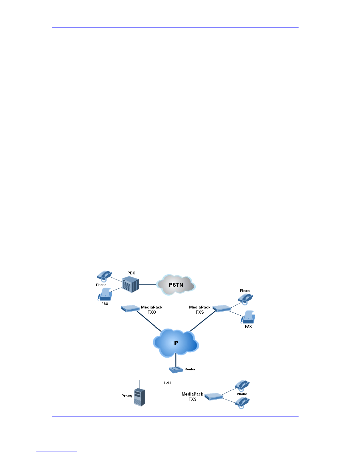
The figure below illustrates a typical MediaPack VoIP application.
Figure 1-1: Typical MediaPack VoIP Application
Page 20
User's Manual 20 Document #: LTRT-65422
MP-11x & MP-124
1.1 MediaPack Models
The analog MediaPack 1xx models and their corresponding supported configurations are
listed in the table below:
Table 1-1: MediaPack 1xx Models and Configurations
MediaPack Model FXS FXO
Combined FXS /
FXO
Number of
Channels
MP-124
Yes No No 24
MP-118
Yes Yes 4 + 4 8
MP-114
Yes Yes 2 + 2 4
MP-112*
Yes No No 2
* The MP-112 differs from the MP-114 and MP-118 in that its configuration excludes the
RS-232 connector and Lifeline option.
1.2 SIP Overview
Session Initiation Protocol (SIP) is an application-layer control (signaling) protocol used on
the gateway for creating, modifying, and terminating sessions with one or more
participants. These sessions can include Internet telephone calls, media announcements,
and conferences.
SIP invitations are used to create sessions and carry session descriptions that enable
participants to agree on a set of compatible media types. SIP uses elements called Proxy
servers to help route requests to the user's current location, authenticate and authorize
users for services, implement provider call-routing policies and provide features to users.
SIP also provides a registration function that enables users to upload their current locations
for use by Proxy servers. SIP implemented in the gateway, complies with the Internet
Engineering Task Force (IETF) RFC 3261 (refer to http://www.ietf.org).
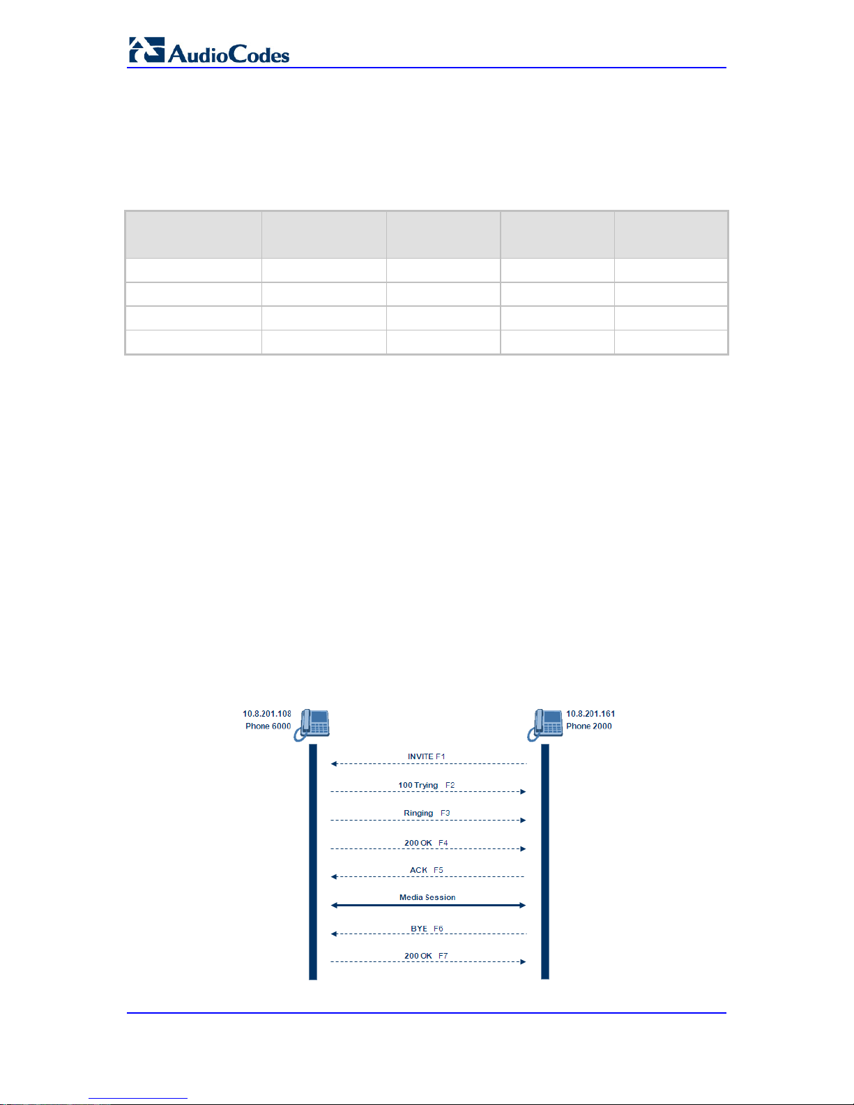
The SIP call flow, shown in the figure below, describes SIP messages exchanged between
two devices during a basic call. In this call flow example, device 10.8.201.108 with phone
number 6000, dials device 10.8.201.161 with phone number 2000.
Figure 1-2: SIP Call Flow
Page 21

Version 6.6 21 MP-11x & MP-124
User's Manual 1. Overview
F1 INVITE - 10.8.201.108 to 10.8.201.161:
INVITE sip:2000@10.8.201.161;user=phone SIP/2.0
Via: SIP/2.0/UDP 10.8.201.108;branch=z9hG4bKacsiJkDGd
From: <sip:6000@10.8.201.108>;tag=1c5354
To: <sip:2000@10.8.201.161>
Call-ID: 534366556655skKw-6000--2000@10.8.201.108
CSeq: 18153 INVITE
Contact: <sip:8000@10.8.201.108;user=phone>
User-Agent: Audiocodes-Sip-Gateway/MediaPack/v.6.60.010.006
Supported: 100rel,em
Allow: REGISTER,OPTIONS,INVITE,ACK,CANCEL,BYE,
NOTIFY,PRACK,REFER,INFO
Content-Type: application/sdp
Content-Length: 208
v=0
o=AudiocodesGW 18132 74003 IN IP4 10.8.201.108
s=Phone-Call
c=IN IP4 10.8.201.108
t=0 0
m=audio 4000 RTP/AVP 8 96
a=rtpmap:8 pcma/8000
a=rtpmap:96 telephone-event/8000
a=fmtp:96 0-15
a=ptime:20
F2 TRYING - 10.8.201.161 to 10.8.201.108:
SIP/2.0 100 Trying
Via: SIP/2.0/UDP 10.8.201.108;branch=z9hG4bKacsiJkDGd
From: <sip:6000@10.8.201.108>;tag=1c5354
To: <sip:2000@10.8.201.161>
Call-ID: 534366556655skKw-6000--2000@10.8.201.108
Server: Audiocodes-Sip-Gateway/MediaPack/v.6.60.010.006
CSeq: 18153 INVITE
Content-Length: 0
F3 RINGING 180 - 10.8.201.161 to 10.8.201.108:
SIP/2.0 180 Ringing
Via: SIP/2.0/UDP 10.8.201.108;branch=z9hG4bKacsiJkDGd
From: <sip:6000@10.8.201.108>;tag=1c5354
To: <sip:2000@10.8.201.161>;tag=1c7345
Call-ID: 534366556655skKw-6000--2000@10.8.201.108
Server: Audiocodes-Sip-Gateway/MediaPack/v.6.60.010.006
CSeq: 18153 INVITE
Supported: 100rel,em
Content-Length: 0
Note: Phone 2000 answers the call and then sends a SIP 200 OK response to
device 10.8.201.108.
F4 200 OK - 10.8.201.161 to 10.8.201.108:
SIP/2.0 200 OK
Via: SIP/2.0/UDP 10.8.201.108;branch=z9hG4bKacsiJkDGd
From: <sip:6000@10.8.201.108>;tag=1c5354
To: <sip:2000@10.8.201.161>;tag=1c7345
Call-ID: 534366556655skKw-6000--2000@10.8.201.108
CSeq: 18153 INVITE
Page 22

User's Manual 22 Document #: LTRT-65422
MP-11x & MP-124
Contact: <sip:2000@10.8.201.161;user=phone>
Server: Audiocodes-Sip-Gateway/MediaPack/v.6.60.010.006
Supported: 100rel,em
Allow: REGISTER,OPTIONS,INVITE,ACK,CANCEL,BYE,
NOTIFY,PRACK,REFER,INFO
Content-Type: application/sdp
Content-Length: 206
v=0
o=AudiocodesGW 30221 87035 IN IP4 10.8.201.161
s=Phone-Call
c=IN IP4 10.8.201.10
t=0 0
m=audio 7210 RTP/AVP 8 96
a=rtpmap:8 pcma/8000
a=ptime:20
a=rtpmap:96 telephone-event/8000
a=fmtp:96 0-15
F5 ACK - 10.8.201.108 to 10.8.201.10:
ACK sip:2000@10.8.201.161;user=phone SIP/2.0
Via: SIP/2.0/UDP 10.8.201.108;branch=z9hG4bKacZYpJWxZ
From: <sip:6000@10.8.201.108>;tag=1c5354
To: <sip:2000@10.8.201.161>;tag=1c7345
Call-ID: 534366556655skKw-6000--2000@10.8.201.108
User-Agent: Audiocodes-Sip-Gateway/MediaPack/v.6.60.010.006
CSeq: 18153 ACK
Supported: 100rel,em
Content-Length: 0
Note: Phone 6000 goes on-hook and device 10.8.201.108 sends a BYE to device
10.8.201.161 and a voice path is established.
F6 BYE - 10.8.201.108 to 10.8.201.10:
BYE sip:2000@10.8.201.161;user=phone SIP/2.0
Via: SIP/2.0/UDP 10.8.201.108;branch=z9hG4bKacRKCVBud
From: <sip:6000@10.8.201.108>;tag=1c5354
To: <sip:2000@10.8.201.161>;tag=1c7345
Call-ID: 534366556655skKw-6000--2000@10.8.201.108
User-Agent: Audiocodes-Sip-Gateway/MediaPack/v.6.60.010.006
CSeq: 18154 BYE
Supported: 100rel,em
Content-Length: 0
F7 OK 200 - 10.8.201.10 to 10.8.201.108:
SIP/2.0 200 OK
Via: SIP/2.0/UDP 10.8.201.108;branch=z9hG4bKacRKCVBud
From: <sip:6000@10.8.201.108>;tag=1c5354
To: <sip:2000@10.8.201.161>;tag=1c7345
Call-ID: 534366556655skKw-6000--2000@10.8.201.108
Server: Audiocodes-Sip-Gateway/MediaPack/v.6.60.010.006
CSeq: 18154 BYE
Supported: 100rel,em
Content-Length: 0
Page 23

Part I
Getting Started with Initial
Connectivity
Page 24

Page 25

Version 6.6 25 MP-11x & MP-124
User's Manual 2. Assigning the OAMP IP Address
2 Assigning the OAMP IP Address
The device is shipped with a factory default IP address for its operations, administration,
maintenance, and provisioning (OAMP) interf ace, as shown in the table below:
Table 2-1: Default OAMP IP Address
IP Address Value
IP Address
FXS and FXS / FXO devices: 10.1.10.10
FXO device: 10.1.10.11
Note: FXO interfaces are applicable only to MP-11x series devices.
Subnet Mask
255.255.0.0
Default Gateway IP
Address
0.0.0.0
The default IP address can be used for initially accessing the device, using any of its
management tools (i.e., embedded Web server, EMS, or Telnet). Once accessed, you can
change this default IP address to correspond with your networking scheme in which the
device is deployed. After changing the IP address, you can re-access the device with this
new OAMP IP address and start configuring and managing the device as desired.
This section describes the different methods for changing the device's default IP address to
suit your networking environment:
Embedded command line interface (CLI) - see 'CLI' on page 28
Embedded HTTP/S-based Web server - see 'Web Interface' on page 25
Bootstrap Protocol (BootP) - see BootP/TFTP Server on page 27
FXS telephone voice menu - see FXS Voice Menu Guidance on page 29
2.1 Web Interface
The procedure below describes how to assign an OAMP IP address using the Web
interface.
To assign an OAMP IP address using the Web interface:
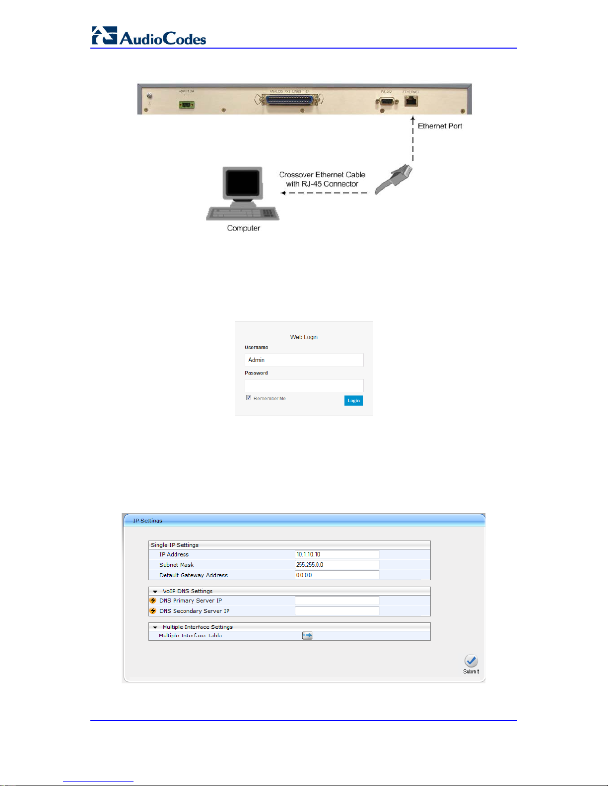
1. Disconnect the network cables (if connected) from the device.
2. Connect the Ethernet port located on the rear panel (labeled Ethernet) directly to the
network interface of your computer, using a st raight-through Ethernet cable.
Figure 2-1: MP-11x Ethernet Connection to PC for Initial Connectivity
Page 26
User's Manual 26 Document #: LTRT-65422
MP-11x & MP-124
Figure 2-2: MP-124 Ethernet Connection to PC for Initial Connectivity
3. Change the IP address and subnet mask of your computer to correspond with the
default IP address and subnet mask of the device.
4. Access the Web interface:
a. On your computer, start a Web browser and in the URL address field, enter the
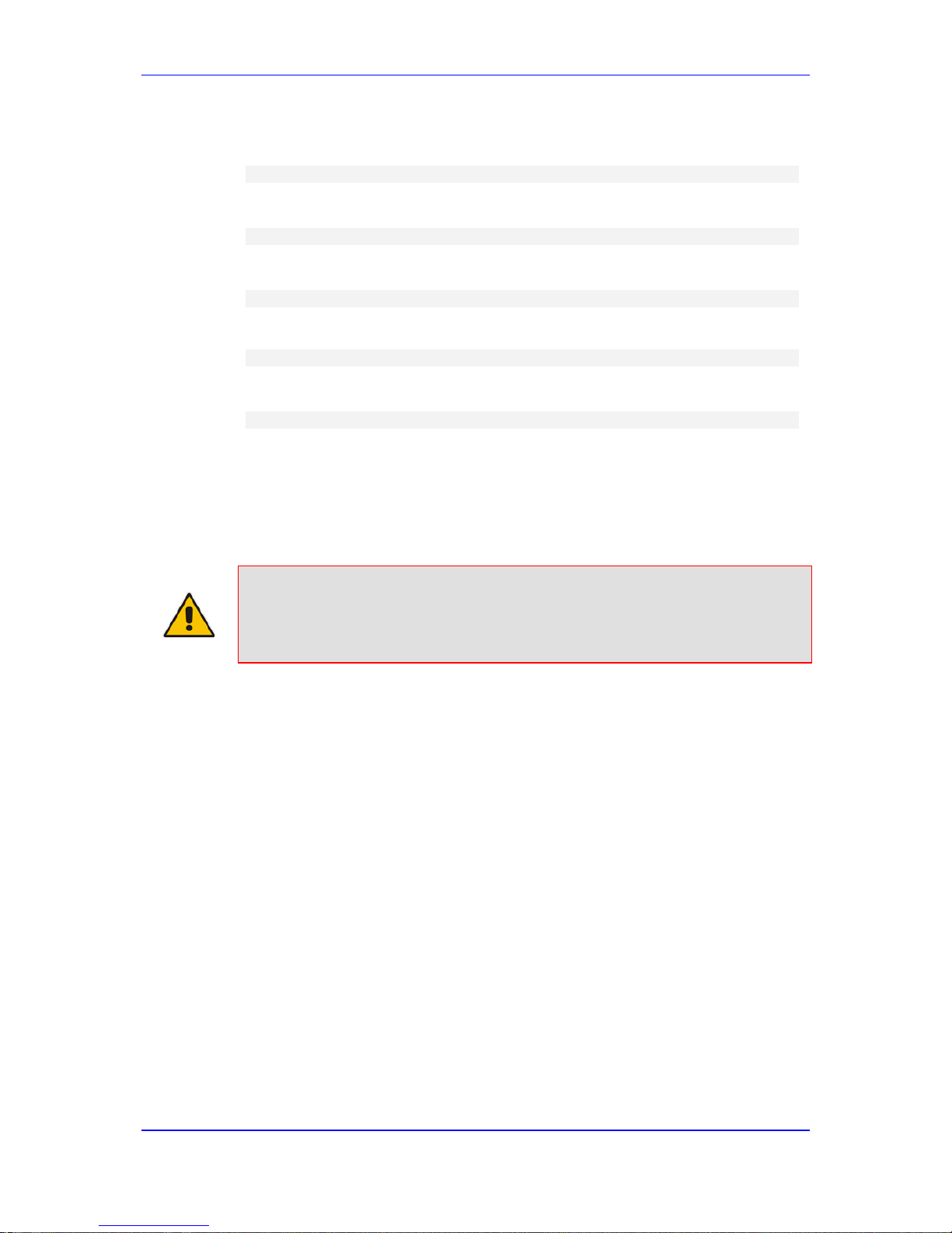
default IP address of the device; the Web interface's Login screen appears:
Figure 2-3: Web Login Screen
b. In the 'Username' and 'Password' fields, enter t he default login user name
("Admin" - case-sensitive) and password ("Admin" - case-sensitive), and then
click Login; the device's Web interface is accessed.
5. Change the default IP address to one that corresponds with your network:
a. Open the Multiple Interface Table page (Configuration tab > VoIP menu >
Network submenu > IP Settings).
Figure 2-4: IP Settings Page (Single Network Interface)
b. Select the 'Index' radio button corresponding to the "OAMP + Media + Control"
application type, and then click Edit.
Page 27

Version 6.6 27 MP-11x & MP-124
User's Manual 2. Assigning the OAMP IP Address
c. Change the IP address, subnet mask, and Default Gateway IP address to
correspond with your network IP addressing sc hem e.
d. Click Apply, and then click Done to validate your settings.
6. Save your settings to the flash memory with a device reset (see Resetting the Device
on page 321).
7. Disconnect the computer from the device and then reconnect the device to your
network.
2.2 BootP/TFTP Server
You can assign an IP address to the device using BootP/TFTP protocols. This can be done
using the AudioCodes AcBootP utility (supplie d) or any standard compatible BootP server.
Note: You can also use the AcBootP utility to load the software file (.cmp) and
configuration file (.ini). For a detailed description of the AcBootP utility, refer
to AcBootP Utility User's Guide.
To assign an IP address using BootP/TFTP:
1. Start the AcBootP utility.
2. Select the Preferences tab, and then set the 'Timeout' field to "50".
3. Select the Client Configuration tab, and then click the Add New Client button.
Figure 2-5: BootP Client Configuration Screen
4. Configure the following fields:
• ‘Client MAC’: Enter the device's MAC address. The MAC address is printed on
the label located on the underside of the device. Ensure that the check box to the
right of the field is selected in order to enable the client.
• 'Client IP’: Enter the new IP address (in dotted-decimal notation) that you want to
assign the device.
Page 28

User's Manual 28 Document #: LTRT-65422
MP-11x & MP-124
• ‘Subnet’: Enter the new subnet mask (in dotted-decimal notation) that you want to
assign the device.
• ‘Gateway’: Enter the IP address of the Default Gateway (if required).
5. Click Apply to save the new client.
6. Physically reset the device by powering it down and then up again. This enables the
device to receive its new networking parameter s through the BootP process.
2.3 CLI
The procedure below describes how to assign an OAMP IP address, using CLI.
Note: Assigning an IP address using CLI is not applicable to MP-112 as this model
does not provide RS-232 serial interface.
To assign an OAMP IP address using CLI:
1. Connect the RS-232 port of the device to the serial communication port on your
computer. For more information, refer to the Hardwa re Instal lati on Manual.
Figure 2-6: MP-11x Serial Connection with PC for CLI Communication
Figure 2-7: MP-124 Serial Connection with PC for CLI Communication
2. Establish serial communication with the device using a terminal emulator program
(such as HyperTerminal) with the following communication port settings:
• Baud Rate: 115,200 bps for MP-124 and 9,600 bps for MP-11x
• Data Bits: 8
• Parity: None
• Stop Bits: 1
• Flow Control: None
Page 29
Version 6.6 29 MP-11x & MP-124
User's Manual 2. Assigning the OAMP IP Address
3. At the prompt, type the following command to access the configuration folder, and
then press Enter:
conf
4. At the prompt, type the following command to view the current network settings, and
then press Enter:
GCP IP
5. At the prompt, typing the following command to change the network settings, and then
press Enter:
SCP IP <ip_address> <subnet_mask> <default_g ateway>
You must enter all three network parameters, ea ch separated by a space, for
example:
SCP IP 10.13.77.7 255.255.0.0 10.13.0.1
6. At the prompt, type the following command to save the settings and reset the device,
and then press Enter:
SAR
2.4 FXS Voice Menu Guidance
You can assign an IP address that suits your networking scheme using a standard touchtone telephone connected to one of the FXS ports. The FXS voice menu can also be used
to query and modify basic configuration parameters.
Notes: If you want to disable the FXS voice menu, do one of the following:
• Set the VoiceMenuPassword parameter t o 'di sable'.
• Change the Web login password for the Admin user from its default value
(i.e., "Admin") to any other value, and then reset the device.
To assign an IP address using the voice menu:
1. Connect a telephone to one of the FXS ports.
2. Lift the handset and dial ***12345 (three stars followed by the digits 1, 2, 3, 4, and 5).
3. Wait for the 'configuration menu' voice prompt to be played.
4. To change the IP address:
a. Press 1 followed by the pound key (#); the current IP address of the device is
played.
b. Press the # key.
c. Dial the new IP address, using the star (*) key instead of periods (.), e.g.,
192*168*0*4, and then press # to finish.
d. Review the new IP address, and then press 1 to save.
5. To change the subnet mask:
a. Press 2 followed by the # key; the current subnet mask of the device is played.
b. Press the # key.
c. Dial the new subnet mask (e.g., 255*255*0*0), and then press # to finish.
d. Review the new subnet mask, and then press 1 to save.
6. To change the Default Gateway IP address:
a. Press 3 followed by the # key; the current Default Gateway address is played.
b. Press the # key.
Page 30

User's Manual 30 Document #: LTRT-65422
MP-11x & MP-124
c. Dial the new Default Gateway address (e.g., 192*168*0*1), and then press # to
finish.
d. Review the new Default Gateway address, and then press 1 to save.
7. Hang up (on-hook) the handset.
Alternatively, initial configuration may be performed using an HTTP server. The Voice
Menu may be used to specify the configuration URL.
To set a configuration URL:
1. Obtain the IP address of the configuration HTTP server (e.g., 36.44.0.6).
2. Connect a telephone to one of the FXS ports.
3. Lift the handset and dial ***12345 (three stars followed by the digits 1, 2, 3, 4, and 5).
4. Wait for the "configuration menu" voice prompt to be played.
5. Dial 31 followed by the # key; the current IP address is played.
6. To change the IP address:
a. Press the # key.
b. Dial the configuration server's IP address. Us e the star (*) key instead of dots
("."), e.g., 36*44*0*6, and then press # to finish.
c. Review the configuration server's IP address, and then press 1 to save.
7. Dial 32 followed by the # key, and then do the following to change the configuration
file name pattern:
a. Press the # key.
b. Select one of the patterns listed in the table belo w (aa.bb.cc.dd denotes the IP
address of the configuration server):
# Configuration File Name Pattern Description
1 http://aa.bb.cc.dd/config.ini Standard config.ini.
2 https://aa.bb.cc.dd/config.ini Secure HTTP.
3 http://aa.bb.cc.dd/audiocodes/<MAC>.ini
The device's MAC address is appended to the file
name (e.g.,
http://36.44.0.6/audiocodes/00908f012300.ini).
4 http://aa.bb.cc.dd:8080/config.ini HTTP on port 8080.
5 http://aa.bb.cc.dd:1400/config.ini HTTP on port 1400.
6
http://aa.bb.cc.dd/cgibin/acconfig.cgi?mac=<MAC>&ip=<IP>
Generating configuration per IP/MAC address
dynamically, using a CGI script. See perl example
below.
a. Press the selected pattern code, and then press # to finish.
8. Press 1 to save, and then hang up the handset. The device retrieves the configuration
from the HTTP server.
The following is an example perl CGI script, suitable for most Apache-based HTTP servers
for generating configuration dynamically per pattern #6 above. Copy this script to
/var/www/cgi-bin/acconfig.cgi on your Apache server and edit it as required:
#!/usr/bin/perl
use CGI;
$query = new CGI;
$mac = $query->param('mac');
$ip = $query->param('ip');
print "Content-type: text/plain\n\n";
print "; INI file generator CGI\n";
Page 31

Version 6.6 31 MP-11x & MP-124
User's Manual 2. Assigning the OAMP IP Address
print "; Request for MAC=$mac IP=$ip\n\n";
print <<"EOF";
SyslogServerIP = 36.44.0.15
EnableSyslog = 1
SSHServerEnable = 1
EOF
The table below lists the configuration parameters that can be viewed and modified using
the voice menu:
Table 2-2: Voice Menu Configuration Parameters
Item Number at
Menu Prompt
Description
1
IP address.
2
Subnet mask.
3
Default Gateway IP address.
4
Primary DNS server IP address.
7
DHCP enable / disable.
31
Configuration server IP address.
32
Configuration file name pattern.
99
Voice menu password (initially 12345).
Note: The voice menu password can also be changed using the Web int erface
or ini file parameter VoiceMenuPassword.
Page 32

User's Manual 32 Document #: LTRT-65422
MP-11x & MP-124
Reader's Notes
Page 33

Part II
Management Tools
Page 34

Page 35

Version 6.6 35 MP-11x & MP-124
User's Manual 3. Introduction
3 Introduction
This part provides an overview of the various management tools that can be used to
configure the device. It also provides step-by-step procedures on how to configure the
management settings.
The following management tools can be used to conf igure the device:
Embedded HTTP/S-based Web server - see 'Web-based Management' on pag e 37
Command Line Interface (CLI) - see 'CLI-Based Management' on page 73
AudioCodes Element Management System - see EMS-Based Management on page
87
Simple Network Management Protocol (SNMP) browser software - see 'SNMP-Based
Management' on page
81
Configuration ini file - see 'INI File-Based Management' on page 89
Notes:
• Some configuration settings can only be done u sing a specific
management tool. For example, some configur ation can only be done
using the Configuration ini file method.
• Throughout this manual, where a parameter is me ntioned, its
corresponding Web, CLI, and ini parameter is mentioned. The ini file
parameters are enclosed in square brackets [.. .].
• For a list and description of all the configuration p arameters, see
'Configuration Parameters Reference' on page 421.
Page 36

User's Manual 36 Document #: LTRT-65422
MP-11x & MP-124
Reader's Notes
Page 37

Version 6.6 37 MP-11x & MP-124
User's Manual 4. Web-Based Management
4 Web-Based Management
The device provides an embedded Web server (hereafter referred to as Web interface),
supporting fault management, configuration, accounting, performance, and security
(FCAPS), including the following:
Full configuration
Software and configuration upgrades
Loading auxiliary files, for example, the Call Progress Tones file
Real-time, online monitoring of the device, including display of alarms and their
severity
Performance monitoring of voice calls and various traffic parameters
The Web interface provides a user-friendly, graphical user interface (GUI), which can be
accessed using any standard Web browser (e.g., Microsoft™ Internet Explorer).
Access to the Web interface is controlled by various security mechanisms such as login
user name and password, read-write privileges, and limiting access to specific IP
addresses.
Notes:
• The Web interface allows you to configure most of the device's settings.
However, additional configuration parameters may exist that are not
available in the Web interface and which can only be configured using
other management tools.
• Some Web interface pages and/or parameters are available only for
certain hardware configurations or software f eatures. The software
features are determined by the installed Software License Key (see
'Software License Key' on page 339).
4.1 Getting Acquainted with the Web Interface
This section provides a description of the Web interf ace.
4.1.1 Computer Requirements
The client computer requires the following to work with the Web interface of the device:
A network connection to the device
One of the following Web browsers:
• Microsoft™ Internet Explorer™ (Version 6.0 and later)
• Mozilla Firefox
®
(Versions 5 through 9.0)
Recommended screen resolutions: 1024 x 768 pixels, or 1280 x 1024 pixels
Note: Your Web browser must be JavaScript-enabled to access t he Web interface.
Page 38

User's Manual 38 Document #: LTRT-65422
MP-11x & MP-124
4.1.2 Accessing the Web Interface
The procedure below describes how to access the Web interface.
To access the Web interface:
1. Open a standard Web browser (see 'Computer Requirements' on page 37).
2. In the Web browser, specify the IP address of the device (e.g., http://10.1.10.10); the
Web interface's Login window appears, as shown below:
Figure 4-1: Web Login Screen
3. In the 'Username' and 'Password' fields, enter the case-sensitive, user name and
password respectively.
4. Click Login; the Web interface is accessed, displaying the Home page. For a detailed
description of the Home page, see 'Viewing the Home P age' on page 59.
Notes:
• The default username and password is "Admin". To change the login
user name and password, see 'Configuring the Web User Accounts' on
page 62.
• If you want the Web browser to remember your password, select the
'Remember Me' check box and then agree to the browser's prompt
(depending on your browser) to save the password f or future logins. On
your next login attempt, simply press the Tab or Enter keys to auto-fill the
'Username' and 'Password' fields, and then cli ck Login.
Page 39

Version 6.6 39 MP-11x & MP-124
User's Manual 4. Web-Based Management
4.1.3 Areas of the GUI
The areas of the Web interface's GUI are shown in the figure below and described in the
subsequent table.
Figure 4-2: Main Areas of the Web Interface GUI
Table 4-1: Description of the Web GUI Areas
Item # Description
1
Displays AudioCodes (corporate) logo image.
2
Displays the product name.
3
Toolbar, providing frequently required command buttons. For more information, see
'Toolbar Description' on page 40.
4
Displays the username of the Web user that is cu rrently logged in.
5
Navigation bar, providing the following tabs for a ccessing various functionalities in
the Navigation tree:
Configuration, Maintenance, and Status & Diagnostics tabs: Access the
configuration menus (see 'Working with Configurati on Pages' on page 43)
Scenarios tab: Creates configuration scenarios (see Working with Scenarios on
page 50)
Search tab: Enables a search engine for searching configuratio n parameters (see
'Searching for Configuration Parameters' on page 49)
6
Navigation tree, displaying a tree-like structur e of elements (configuration menus,
Scenario steps, or search engine) pertaining to t he selected tab on the Navigation
bar. For more information, see 'Navigation Tree' on page 41.
7
Work pane, displaying the configuration page of t he selected menu in the Navigation
tree. This is where configuration is done. For more inf orm ation, see 'Working with
Configuration Pages' on page 43.
Page 40

User's Manual 40 Document #: LTRT-65422
MP-11x & MP-124
4.1.4 Toolbar Description
The toolbar provides frequently required command buttons, described in the table below:
Table 4-2: Description of Toolbar Buttons
Icon Button
Name
Description
Submit
Applies parameter settings to the device (see 'Saving Configuration'
on page 324).
Note: This icon is grayed out when not applicable to the currently
opened page.
Burn
Saves parameter settings to flash memory (see 'Saving
Configuration' on page 324).
Device
Actions
Opens a drop-down list with frequently needed commands:
Load Configuration File: Opens the Configuration File page for
loading an ini file to the device (see 'Backing Up and Loading
Configuration File' on page 346).
Save Configuration File: Opens the Configuration File page for
saving the ini file to a folder on a computer (see 'Backing Up and
Loading Configuration File' on page 346).
Reset: Opens the Maintenance Actions page for performing
various maintenance procedures such as resett i ng the device
(see 'Resetting the Device' on page 321).
Software Upgrade Wizard: starts the Software Upgrade wizard
for upgrading the device's software (see 'Sof tware Up grade
Wizard' on page 343).
Home
Opens the Home page (see 'Viewing the Home Page' on page 59).
Help
Opens the Online Help topic of the currently opened configuration
page (see 'Getting Help' on page 58).
Log off
Logs off a session with the Web interface (see 'Logging O ff the Web
Interface' on page 59).
Note: If you modify a parameter that takes effect only after a device reset, after you
click the Submit
button in the configuration page, the toolbar displays
"Reset", as shown in the figure below. This is a reminder that you need to
later save your settings to flash memory and reset the device.
Figure 4-3: "Reset" Displayed on Toolbar
Page 41

Version 6.6 41 MP-11x & MP-124
User's Manual 4. Web-Based Management
4.1.5 Navigation Tree
The Navigation tree is located in the Navigation pane and displays a tree-like structure of
menus pertaining to the selected tab on the Navigation bar. You can drill-down to the
required page item level to open its corresponding page i n the Work pane.
The terminology used throughout this manual for referring to the hierarchical structure of
the tree is as follows:
Menu: first level (highest level)
Submenu: second level - contained within a menu
Page item: last level (lowest level in a menu) - contained within a menu or submenu
Figure 4-4: Navigating in Hierarchical Menu Tree (Example)
Note: The figure above is used only as an example. The displayed menus depend
on supported features based on the Software License Key installed on your
device.
4.1.5.1 Displaying Navigation Tree in Basic and Full View
You can view an expanded or reduced display of the Navigation tree. This affects the
number of displayed menus and submenus in the tree. The expanded (Full) view displays
all the menus pertaining to the selected configuration tab; the reduced (Basic) view
displays only commonly used menus. This is relevant when using the configuration tabs
Page 42

User's Manual 42 Document #: LTRT-65422
MP-11x & MP-124
(i.e., Configuration, Maintenance, and Status & Diagnostics) on the Navigation bar. The
advantage of the Basic view is that it prevents "cluttering" of the Navigation tree with
menus that may not be required.
To toggle between Full and Basic view:
To display a reduced menu tree, select the Basic option (default).
To display all the menus and submenus in the Navigation tree, select the Full option.
Figure 4-5: Basic and Full View Options
Notes:
• After you reset the device, the Web GUI is display ed in Basic view.
• When in Scenario mode (see Scenarios on page 50), the Navigation tree
is displayed in Full view.
4.1.5.2 Showing / Hiding the Navigation Pane
You can hide the Navigation pane to provide more space for elements displayed in the
Work pane. This is especially useful when the Work pane displays a wide table. The arrow
button located below the Navigation bar is used to hi de and show the pane.
To hide and show the Navigation pane:
To hide the Navigation pane: Click the left-pointing arrow ; the pane is hidden
and the button is replaced by the right-pointing arrow butt on.
Page 43

Version 6.6 43 MP-11x & MP-124
User's Manual 4. Web-Based Management
To show the Navigation pane: Click the right-pointing arrow ; the pane is
displayed and the button is replaced by the left-pointi ng arrow button.
Figure 4-6: Show and Hide Button (Navigation Pane in Hide View)
4.1.6 Working with Configuration Pages
The configuration pages contain the parameters for configuring the device and are
displayed in the Work pane.
4.1.6.1 Accessing Pages
The configuration pages are accessed by clicking the required page item in the Navigation
tree.
To open a configuration page:
1. On the Navigation bar, click the required tab (Configuration, Maintenance, or Status
& Diagnostics); the menus pertaining to the selected tab appear in the Navigation
tree.
2. Navigate to the required page item, by performing the following:
• Drill-down using the plus sign to expand the menu and submenus.
• Drill-up using the minus sign to collapse the menu and submenus.
3. Click the required page item; the page opens in the Work pane.
You can also access previously opened pages by clicking the Web browser's Back button
until you have reached the required page. This is useful if you want to view pages in which
you have performed configurations in the current Web session.
Notes:
• You can also access certain pages from the Device Acti o ns button
located on the toolbar (see 'Toolbar Description' on page 40).
• To view all the menus in the Navigation tree, ensure that the Navigation
tree is in Full view (see 'Displaying Navigation Tree in B asic and Full
View' on page 41).
• To get Online Help for the currently displayed pag e, see 'Getting Help' on
page 58.
• Certain pages may not be accessible or may be read-only, depending on
the access level of your Web user account (see 'Con figuri ng Web User
Accounts' on page 62). If a page is read-only, "Read-Only Mode" is
displayed at the bottom of the page.
Page 44

User's Manual 44 Document #: LTRT-65422
MP-11x & MP-124
4.1.6.2 Viewing Parameters
Some pages allow you to view a reduced or expanded display of parameters. The Web
interface provides two methods for displaying page parameters:
Displaying "basic" and "advanced" parameters - see 'Displaying Basic and A dvanced
Parameters' on page
44
Displaying parameter groups - see 'Showing / Hiding Parameter Groups' on page 45
4.1.6.2.1 Displaying Basic and Advanced Parameters
Some pages provide a toggle button that allows you to show and hide parameters that
typically are used only in certain deployments. This button is located on the top-right corner
of the page and has two display states:
Advanced Parameter List button with down-pointing arrow: click this button to
display all parameters.
Basic Parameter List button with up-pointing arrow: click this button to show only
common (basic) parameters.
The figure below shows an example of a page displaying basic parameters only. If you
click the Advanced Parameter List button (shown below), the page will also display the
advanced parameters.
Figure 4-7: Toggling between Basic and Advanced View
Notes:
• When the Navigation tree is in Full mode (see 'Navigat i on Tree' on page
41), configuration pages display all their param eters.
• If a page contains only basic parameters, the Basic Parameter List
button is not displayed.
• If you reset the device, the Web pages display only the basic parameters.
• The basic parameters are displayed in a dark blue background.
Page 45

Version 6.6 45 MP-11x & MP-124
User's Manual 4. Web-Based Management
4.1.6.2.2 Showing / Hiding Parameter Groups
Some pages provide groups of parameters, which can be hidden or shown. To toggle
between hiding and showing a group, simply click the group title button that appears above
each group. The button appears with a down-pointing or up-pointing arrow, indicating that it
can be collapsed or expanded when clicked, respectively.
Figure 4-8: Expanding and Collapsing Parameter Groups
4.1.6.3 Modifying and Saving Parameters
When you modify a parameter value on a page, the Edit symbol appears to the right of
the parameter. This indicates that the parameter has been modified, but has yet to be
applied (submitted). After you apply your modifications, the symbol disappears.
Figure 4-9: Edit Symbol after Modifying Parameter Value
To save configuration changes on a page to the device's volatile memory (RAM),
do one of the following:
On the toolbar, click the Submit button.
At the bottom of the page, click the Submit button.
When you click Submit, modifications to parameters with on-the-fly capabilities are
immediately applied to the device and take effect. Parameters displayed on the page with
the lightning symbol take effect only after a device reset. For resetting the device, see
'Resetting the Device' on page 321.
Page 46

User's Manual 46 Document #: LTRT-65422
MP-11x & MP-124
Note: Parameters saved to the volatile memory (by clicking Submit), revert to their
previous settings after a hardware or software reset, or if the device is
powered down. Therefore, to ensure parameter changes (whether on-the-fly
or not) are retained, save ('burn') them to the device's non-volatile memory,
i.e., flash (see 'Saving Configuration' on page 324).
If you enter an invalid parameter value (e.g., not in the range of permitted values) and then
click Submit, a message box appears notifying you of the invalid value. In addition, the
parameter value reverts to its previous value and is highlighted in red, as shown in the
figure below:
Figure 4-10: Value Reverts to Previous Valid Value
4.1.6.4 Working with Tables
This section describes how to work with configuration tables, which are provided in basic or
enhanced design, depending on the configuration page.
4.1.6.4.1 Basic Design Tables
A few of the tables in the Web interface are in basic design format. The figure below
displays a typical table in the basic design format and the subsequent table describes its
command buttons.
Figure 4-11: Adding an Index Entry to a Table
Table 4-3: Basic Table Design Description
Item # Button / Field
1
Add Index (or Add) button Adds an index entry row to t he table.
2 Edit
Edits the selected row.
3 Delete
Removes the selected row from the table.
4
'Add Index' field
Defines the index number. When adding a new row, enter
the required index number in this field, and then click Add
Page 47

Version 6.6 47 MP-11x & MP-124
User's Manual 4. Web-Based Management
Item # Button / Field
Index.
5
Index radio button Selects the row for edit i ng and deleting.
-
Compact button
Organizes the index entries in ascending, consecuti ve
order, starting from index 0. For example, assume you
have three index entries, 0, 4 and 6. After you click
Compact, index entry 4 is re-
assigned to index 1 and index
entry 6 is re-assigned to index 2.
- Apply button Saves the row configuration. Click this button after you add
or edit each index entry.
4.1.6.4.2 Enhanced Design Tables
Most of the tables in the Web interface are designed in the enhanced table format. The
figure below displays a typical table in the enhanced design format and the subsequent
table describes its command buttons and areas.
Figure 4-12: Displayed Details Pane
Table 4-4: Enhanced Table Design Description
Item # Button
1 Add
Adds a new index entry row to the table. When you click this button, a
dialog box appears with parameters for config uring the new entry.
When you have completed configuration, click the Submit but ton in
the dialog box to add it to the table.
2 Edit
Edits the selected row.
3 Delete
Removes the selected row from the table. When you click this button,
a confirmation box appears requesting you to conf irm deletion. Click
Delete to accept deletion.
Page 48

User's Manual 48 Document #: LTRT-65422
MP-11x & MP-124
Item # Button
4 Show/Hide
Toggles between displaying and hiding the full configuration of a
selected row. This configuration is displayed bel ow the table (see Item
#6) and is useful for large tables that cannot displ ay all its columns in
the work pane.
5
- Selected inde x row entry for editing, deleting and showing
configuration.
6
- Displays the full configuration of the selected row when you click the
Show/Hide button.
7
- Links to access additional configuration tables related to the current
configuration.
If the configuration of an entry row is invalid, the index of the row is highlighted in red, as
shown below:
Figure 4-13: Invalid Configuration with Index Highlighted in Red
The table also enables you to define the number of rows to display on the page and to
navigate between pages displaying multiple rows. This is done using the page navigation
area located below the table, as shown in the figure b el ow:
Figure 4-14: Viewing Table Rows per Page
Table 4-5: Row Display and Page Navigation
Item # Description
1
Defines the page that you want to view. Enter the requi red page number or use the
following page navigation buttons:
- Displays the next page
- Displays the last page
- Displays the previous page
- Displays the first page
2
Defines the number of rows to display per page. You can select 5 or 10, where the
Page 49

Version 6.6 49 MP-11x & MP-124
User's Manual 4. Web-Based Management
Item # Description
default is 10.
3
Displays the currently displayed page number.
4.1.7 Searching for Configuration Parameters
You can locate the exact Web page on which a specific parameter appears, by using the
device's Search feature. The Web parameter's corresponding ini file parameter name is
used as the search key. The search key can include the full parameter name (e.g.,
"EnableIPSec") or a substring of it (e.g., "sec"). If you search for a substring, all parameters
containing the specified substring in their names are listed in the search result.
Note: If an ini file parameter is not configurable in the Web interface, the search
fails.
To search for a parameter:
1. On the Navigation bar, click the Search tab; the Search engine appears in the
Navigation pane.
2. In the field alongside the Search button, enter the parameter name or a substring of
the name for which you want to search. If you have done a previous search for such a
parameter, instead of entering the required string, you can use the 'Search History'
drop-down list to select the string saved from a previous search.
3. Click Search; a list of found parameters based on your search key appears in the
Navigation pane. Each searched result display s t he following:
• ini file parameter name
• Link (in green) to the Web page on which the parameter appears
• Brief description of the parameter
• Menu navigation path to the Web page on which the para m eter appears
4. In the searched list, click the required parameter (green link) to open the page on
which the parameter appears; the relevant page opens in the Work pane and the
searched parameter is highlighted in the page for easy identification, as shown in the
figure below:
Figure 4-15: Searched Result Screen
Page 50

User's Manual 50 Document #: LTRT-65422
MP-11x & MP-124
Table 4-6: Search Description
Item # Description
1
Search field for entering search key and Search button for activating the search
process.
2
Search results listed in Navigation pane.
3
Found parameter, highlighted on relevant Web page
4.1.8 Working with Scenarios
The Web interface allows you to create your own menu (Scenario) of up to 20 pages,
selected from the menus in the Navigation tree (i.e., pertaining to the Configuration,
Maintenance, and Status & Diagnostics tabs). Each page in the Scenario is referred to
as a Step. For each Step, you can select up to 25 parameters on the page to include in the
Scenario. Therefore, the Scenario feature is useful in that it allows you quick-and-easy
access to commonly used configuration parameters specific to your network environment.
When you log in to the Web interface, your Scenario is displayed in the Navigation tree.
Instead of creating a new Scenario, you can load a saved Scenario on a computer to the
device (see 'Loading a Scenario to the Device' on page 55).
4.1.8.1 Creating a Scenario
The procedure below describes how to create a Scenario.
To create a Scenario:
1. On the Navigation bar, click the Scenarios tab; a message box appears, requesting
you to confirm creation of a Scenario:
Figure 4-16: Create Scenario Confirmation Message Box
Note: If a Scenario already exists, the Scenario Loading message box appears.
2. Click OK; the Scenario mode appears in the Navigation tree as well as the menus of
the Configuration tab.
3. In the 'Scenario Name' field, enter an arbitrary name for the Scenario.
4. On the Navigation bar, click the Configuration or Maintenance tab to display their
respective menus in the Navigation tree.
5. In the Navigation tree, select the required page item for the Step, and then in the page
itself, select the required parameters by selecting the check boxes corresponding to
the parameters.
6. In the 'Step Name' field, enter a name for the Step.
7. Click the Next button located at the bottom of the page; the Step is added to the
Scenario and appears in the Scenario Step list.
Page 51

Version 6.6 51 MP-11x & MP-124
User's Manual 4. Web-Based Management
8. Repeat steps 5 through 7 to add additional Steps (i.e., pages).
9. When you have added all the required Steps for your Scenario, click the Save &
Finish button located at the bottom of the Navigation tree; a message box appears
informing you that the Scenario has been successfully created.
10. Click OK; the Scenario mode is quit and the menu tree of the Configuration tab
appears in the Navigation tree.
Figure 4-17: Creating a Scenario
Table 4-7: Scenario Description
Description
1
Selected page item in the Navigation tree whose page contains the parameter that you
want to add to the Scenario Step.
2
Name of a Step that has been added to the Scenario.
3
'Scenario Name' field for defining a name for the Scenario.
4
'Step Name' field for defining a name for a Scenario Step.
5
Save & Finish button to save your Scenario.
6
Selected parameter(s) that you want added to a S cenario Step.
7
Next button to add the current Step to the Scenario and enables you to add additional
Steps.
Page 52

User's Manual 52 Document #: LTRT-65422
MP-11x & MP-124
Notes:
• You can add up to 20 Steps per Scenario, where each Step can contain
up to 25 parameters.
• When in Scenario mode, the Navigation tree is in 'Full' display (i.e., all
menus are displayed in the Navigation tree) and the configuration pages
are in 'Advanced Parameter List' display (i.e. , all parameters are shown
in the pages). This ensures accessibility to all parameters when creating
a Scenario. For a description on the Navigati on tree views, see
'Navigation Tree' on page 41.
• If you previously created a Scenario and you click t he Create Scenario
button, the previously created Scenario is deleted and replaced with the
one you are creating.
• Only Security Administrator Web users can create S cenarios.
4.1.8.2 Accessing a Scenario
Once you have created the Scenario, you can access it by following the procedure below:
To access the Scenario:
1. On the Navigation bar, select the Scenario tab; a message box appears, requesting
you to confirm the loading of the Scenario.
2. Click OK; the Scenario and its Steps appear in the Navigation tree, as shown in the
example below:
Figure 4-18: Scenario Example
Table 4-8: Loaded Scenario Description
Item Description
1
Scenario name.
2
Scenario Steps.
3
Scenario configuration command buttons.
4
Parameters available on a page for the selecte d Scenario Step. These are displayed in
a blue background; unavailable parameters are displayed in a gray or light-blue
Page 53
Version 6.6 53 MP-11x & MP-124
User's Manual 4. Web-Based Management
Item Description
background.
5
Navigation buttons for navigating between S cenario Steps:
Next button to open the next Step listed in the Scenario
Previous button to open the previous Step listed in the Scenario
Note: If you reset the device while in Scenario mode, after the device resets, you
are returned once again to the Scenario mode.
4.1.8.3 Editing a Scenario
You can modify a Scenario as described in the proced ure below.
Note: Only Security Administrator Web users can edit a S cenario.
To edit a Scenario:
1. Open the Scenario.
2. Click the Edit Scenario button located at the bottom of the Navigation pane; the
'Scenario Name' and 'Step Name' fields appear.
3. You can perform the following edit operations:
• Add Steps:
a. On the Navigation bar, select the desired tab (i.e., Configuration or
Maintenance); the tab's menu appears in the Nav i gation tree.
b. In the Navigation tree, navigate to the desired page item; the corresponding
page opens in the Work pane.
c. On the page, select the required parameters by marking their corresponding
check boxes.
d. Click Next.
• Add or Remove Parameters:
a. In the Navigation tree, select the required Step; the corresponding page
opens in the Work pane.
b. To add parameters, select the check boxes corresponding to the desired
parameters.
c. To remove parameters, clear the check boxes corresponding to the desired
parameters.
d. Click Next.
• Edit Step Name:
a. In the Navigation tree, select the required Step.
b. In the 'Step Name' field, modify the Step name.
c. On the page, click Next.
Page 54

User's Manual 54 Document #: LTRT-65422
MP-11x & MP-124
• Edit Scenario Name:
a. In the 'Scenario Name' field, edit the Scenario name.
b. On the displayed page, click Next.
• Remove a Step:
a. In the Navigation tree, select the required Step; the corresponding page
opens in the Work pane.
b. On the page, clear all the check boxes corresponding to the parameters.
c. Click Next.
4. After clicking Next, a message box appears notifying you of the change. Click OK.
5. Click Save & Finish; a message box appears informing you that the Scenario has
been successfully modified. The Scenario mode is exited and the menus of the
Configuration tab appear in the Navigation tree.
4.1.8.4 Saving a Scenario to a PC
You can save a Scenario (as a dat file) to a folder on your computer. This is useful when
you need multiple Scenarios to represent different deployments. Once you create a
Scenario and save it to your computer, you can then keep on saving modifications to it
under different Scenario file names. When you require a specific network environment
setup, you can load the suitable Scenario file from your computer (see 'Loading a Scenario
to the Device' on page 55).
To save a Scenario to a computer:
1. On the Navigation bar, click the Scenarios tab; the Scenario appears in the
Navigation tree.
2. Click the Get/Send Scenario File button, located at the bottom of the Navigation tree;
the Scenario File page appears, as shown below:
Figure 4-19: Scenario File Page
3. Click the Get Scenario File button; the File Download window appears.
4. Click Save, and then in the Save As window navigate to the folder to where you want
to save the Scenario file. When the file is successfully downloaded to your computer,
the Download Complete window appears.
5. Click Close to close the window.
Page 55

Version 6.6 55 MP-11x & MP-124
User's Manual 4. Web-Based Management
4.1.8.5 Loading a Scenario to the Device
The procedure below describes how to load a previously saved Scenario file (data file)
from your computer to the device. For saving a Scenario, see 'Saving a Scenario to a PC'
on page 54.
To load a Scenario to the device:
1. On the Navigation bar, click the Scenarios tab; the Scenario appears in the
Navigation tree.
2. Click the Get/Send Scenario File button, located at the bottom of the Navigation tree;
the Scenario File page appears.
3. Click the Browse button, and then navigate to the Scenario file saved on your
computer.
4. Click the Send File button.
Notes:
• You can only load a Scenario file to a device that has the same hardware
configuration as the device on which it was create d.
• The loaded Scenario replaces any existing Scenario.
• You can also load a Scenario file using BootP, by loading an i ni file that
contains the ini file parameter ScenarioFi l eName (see Web and Telnet
Parameters on page 431). The Scenario file must be located i n the same
folder as the ini file. For information on using AudioCodes AcBootP utility,
refer to AcBootP Utility User's Guide.
4.1.8.6 Deleting a Scenario
You can delete the Scenario, as described in the procedure below.
To delete the Scenario:
1. On the Navigation bar, click the Scenarios tab; a message box appears, requesting
you to confirm:
2. Click OK; the Scenario mode appears in the Navigation tree.
3. Click the Delete Scenario File button; a message box appears requesting
confirmation for deletion.
Figure 4-20: Message Box for Confirming Scenario Deletion
Page 56

User's Manual 56 Document #: LTRT-65422
MP-11x & MP-124
4. Click OK; the Scenario is deleted and the Scenario mode closes.
Note: You can also delete a Scenario using the following alternative methods:
• Loading an empty dat file (see 'Loading a Scenario to the Device' on
page 55).
• Loading an ini file with the ScenarioFileName parameter set to no value
(i.e., ScenarioFileName = "").
4.1.8.7 Quitting Scenario Mode
Follow the procedure below to quit the Scenario mode.
To quit the Scenario mode:
1. On the Navigation bar, click any tab except the Scenarios tab, or click the Cancel
Scenarios button located at the bottom of the Navigation tree; a message box
appears, requesting you to confirm exiting Scen ario mode, as shown below.
Figure 4-21: Confirmation Message Box for Exiting Scenario Mode
2. Click OK to exit.
Page 57

Version 6.6 57 MP-11x & MP-124
User's Manual 4. Web-Based Management
4.1.9 Creating a Login Welcome Message
You can create a Welcome message box that is displayed on the Web Login page for
logging in to the Web interface. The figure below displays an example of a Welcome
message:
Figure 4-22: User-Defined Web Welcome Message after Login
To enable and create a Welcome message, use the WelcomeMessage table ini file
parameter. If this parameter is not configured, no Welcome message is displayed.
Table 4-9: ini File Parameter for Welcome Login Message
Parameter Description
[WelcomeMessage]
Enables and defines a Welcome message that appears on the Web Login
page for logging in to the Web interface.
The format of this parameter is as follows:
[WelcomeMessage]
FORMAT WelcomeMessage_Index = WelcomeM essage_Text;
[\WelcomeMessage]
For Example:
[WelcomeMessage ]
FORMAT WelcomeMessage_Index = WelcomeMessage_Text;
WelcomeMessage 1 = "*********************************";
WelcomeMessage 2 = "********* This is a Welcome m essage **";
WelcomeMessage 3 = "*********************************";
[\WelcomeMessage]
Each index row represents a line of text in the Wel come message box. Up
to 20 lines (or rows) of text can be defined.
Page 58

User's Manual 58 Document #: LTRT-65422
MP-11x & MP-124
4.1.10 Getting Help
The Web interface provides you with context-sensitive Online Help. The Online Help
provides brief descriptions of parameters pertaining to the currently opened page.
To view the Help topic of a currently opened page:
1. On the toolbar, click the Help button; the Help topic pertaining to the opened
page appears, as shown below:
Figure 4-23: Help Topic for Current Page
2. To view a description of a parameter, click the plus sign to expand the parameter.
To collapse the description, click the minus sign.
3. To close the Help topic, click the close button located on the top-right corner of
the Help topic window or simply click the Help button.
Note: Instead of clicking the Help button for each page you open, you can open it
once for a page and then simply leave it open. Each time you open a different
page, the Help topic pertaining to that page is automatically displayed.
Page 59

Version 6.6 59 MP-11x & MP-124
User's Manual 4. Web-Based Management
4.1.11 Logging Off the Web Interface
The procedure below describes how to log off the Web interface.
To log off the Web interface:
1. On the toolbar, click the Log Off icon; the following confirmation message box
appears:
Figure 4-24: Log Off Confirmation Box
2. Click OK; you are logged off the Web session and the Web Login dialog box appears
enabling you to re-login, if required.
4.2 Viewing the Home Page
The Home page is displayed when you access the device's Web interface. The Home page
provides you with a graphical display of the device's front panel, showing color-coded
status icons for various operations device.
To access the Home page:
On the toolbar, click the Home icon.
Figure 4-25: MP-11x Home Page
Figure 4-26: MP-124 Home Page
Note: The displayed number and type (FXO and/or FXS) of channels depends on
the ordered model (e.g., MP-118 or MP-114).
Page 60

User's Manual 60 Document #: LTRT-65422
MP-11x & MP-124
In addition to the color-coded status information depicted on the graphical display of the
device, the Home page displays various read-only information in the General Information
pane:
IP Address: IP address of the device
Subnet Mask: Subnet mask address of the device
Default Gateway Address: Default gateway used by the device
Firmware Version: Software version running on the device
Protocol Type: Signaling protocol currently used by the device (i.e. SIP)
Gateway Operational State:
• "LOCKED": device is locked (i.e. no new calls are a cc epted)
• "UNLOCKED": device is not locked
• "SHUTTING DOWN": device is currently shutting down
To perform these operations, see 'Basic Maintenanc e' on page 321.
The table below describes the areas of the Home page.
Table 4-10: Home Page Description
Label Description
Alarms
Displays the highest severity of an active alarm r ai sed (if any) by the device:
Green = no alarms
Red = Critical alarm
Orange = Major alarm
Yellow = Minor alarm
To view active alarms, click this Alarms area to open the Active Alarms page (see
Viewing Active Alarms on page 363).
Channel/Ports
Displays the status of the ports (channels):
(red): Line not connected or port out of service due to Serial Peripheral
Interface (SPI) failure (applicable only to FXO i nterfaces)
(grey): Channel inactive
(blue): Handset is off-hook
(green): Active RTP stream
If you click a port, a shortcut menu appears with co mmands allowing you to
perform the following:
(Analog ports only) Reset the channel port (see Resetting an Anal og Channel
on page 325)
View the port settings (see 'Viewing Analog Port Information' on page 365)
Assign a name to the port (see 'Assigning a Port Name' on page 61)
Uplink (MP-11x)
LAN (MP-124
If clicked, the Ethernet Port Information page opens, displaying Ethernet port
configuration settings (see Viewing Ethernet P ort Information on page 362).
Fail
Currently not supported.
Ready
Currently not supported.
Power
Always lit green, indicating power received by the device.
Page 61

Version 6.6 61 MP-11x & MP-124
User's Manual 4. Web-Based Management
4.2.1 Assigning a Port Name
The Home page allows you to assign an arbitrary name or a brief description to each port.
This description appears as a tooltip when you move y our m ouse over the port.
Note: Only alphanumerical characters can be used in the port description.
To add a port description:
1. Click the required port icon; a shortcut menu appears, as shown below:
Figure 4-27: Shortcut Menu (Example using MP-11x)
2. From the shortcut menu, choose Update Port Info; a text box appears.
Figure 4-28: Typing in Port Name (Example using MP-11x)
3. Type a brief description for the port, and then click Apply Port Info.
Page 62

User's Manual 62 Document #: LTRT-65422
MP-11x & MP-124
4.3 Configuring Web User Accounts
You can create up to 5 Web user accounts for the device. Up to five Web users can
simultaneously be logged in to the device's Web interface. Web user accounts prevent
unauthorized access to the Web interface, enabling login access only to users with correct
credentials (i.e., username and password). Each Web user account is composed of the
following attributes:
Username and password: Credentials that enable authorized login acce ss to the
Web interface.
Access level (user type): Access privileges specifying what the user can v i ew i n the
Web interface and its read/write privileges. The t abl e below describes the different
types of Web user account access levels:
Table 4-11: Access Levels of Web User Accounts
User Access Level
Numeric
Representation*
Privileges
Master
220
Read / write privileges for all pages. Can create all user
types, including additional Master users and Security
Administrators. It can delete all users except t he last
Security Administrator.
Security
Administrator
200
Read / write privileges for all pages. It can create all user
types and is the only one that can create the first Master
user.
Note: There must be at least one Security Administrator.
Administrator
100
Read / write privileges for all pages except securityrelated pages, which are read-only.
Monitor
50
No access to security-related and file-loading page s;
read-only access to other pages.
No Access
0
No access to any page.
Note: This access level is not applicable when using
advanced Web user account configuration in t he Web
Users table.
* The numeric representation of the access level i s used only to define accounts in a RADIUS server
(the access level ranges from 1 to 255).
By default, the device is pre-configured with the fol lowing two Web user accounts:
Table 4-12: Pre-configured Web User Accounts
User Access Level Username
(Case-Sensitive)
Password
(Case-Sensitive)
Security Administrator
Admin Admin
Monitor
User User
After you log in to the Web interface, the usernam e i s displayed on the toolbar.
If the Web session is idle (i.e., no actions are performed) for more than five minutes, the
Web session expires and you are once again requested to login with your username and
password. Users can be banned for a period of time upon a user-defined number of
Page 63

Version 6.6 63 MP-11x & MP-124
User's Manual 4. Web-Based Management
unsuccessful login attempts. Login information (such as how many login attempts were
made and the last successful login time) can be presented to the user.
To prevent user access after a specific number of failed logins:
1. From the 'Deny Access On Fail Count' drop-down list, select the number of failed
logins after which the user is prevented access to the device for a user-defined time
(see next step).
2. In the 'Deny Authentication Timer' field, enter the interval (in seconds) that the user
needs to wait before a new login attempt from the same IP address can be done after
reaching the number of failed login attempts (defi ned in the previous step).
Notes:
• For security, it's recommended that you change the default username
and password.
• The Security Administrator user can change all attributes of all Web user
accounts. Web users with access levels other than Security Administrator
can change only their password and username.
• To restore the two Web user accounts to default sett ings (usernames
and passwords), set the ini file parameter ResetWebPasswo rd to 1.
• To log in to the Web interface with a different Web user, click the Log off
button and then login with with a different username and password.
• You can set the entire Web interface to read-only (regardless of Web
user access levels), by using the ini file parameter DisableWeb Conf ig
(see 'Web and Telnet Parameters' on page 431).
• You can define additional Web user accounts usin g a RADIUS server
(see 'Configuring RADIUS Settings' on page 72).
4.3.1 Basic User Accounts Configuration
This section describes basic Web user account configuration. This is relevant only if the
two default, pre-configured Web user accounts - Security Administrator ("Admin") and
Monitor ("User") - are sufficient for your management scheme.
For the Security Administrator, you can change only the username and password; not its
access level. For the Monitor user, you can change username and password as well as
access level (Administrator, Monitor, or No Ac cess).
Notes:
• The access level of the Security Administrator ca nnot be modified.
• The access level of the second user account can be m odi fied only by the
Security Administrator.
• The username and password can be a string of up to 19 cha racters.
When you log in to the Web interface, the username and password string
values are case-sensitive, according to your conf i guration.
• Up to two users can be logged in to the Web interface at the same time,
and they can be of the same user.
Page 64

User's Manual 64 Document #: LTRT-65422
MP-11x & MP-124
To configure the two pre-configured Web user accounts:
1. Open the Web User Accounts page (Configuration tab > System menu > Web User
Accounts). If you are logged in as Security Administrator, both Web user accounts
are displayed (as shown below). If you are logged in with the second user account,
only the details of this user account are displayed.
Figure 4-29: WEB User Accounts Page (for Users with 'Security Admin istrator' Privileges)
2. To change the username of an account:
a. In the 'User Name' field, enter the new user name.
b. Click Change User Name; if you are currently logged in to the Web interface with
this account, the 'Web Login' dialog box appears.
c. Log in with your new user name.
3. To change the password of an account:
a. In the 'Current Password' field, enter the current password.
b. In the 'New Password' and 'Confirm New Password' fields, enter the new
password.
c. Click Change Password; if you are currently logged in to the Web interface with
this account, the 'Web Login' dialog box appears.
d. Log in with your new password.
4. To change the access level of the optional, second account:
a. Under the Account Data for User: User group, from the 'Access Level' drop-
down list, select a new access level user.
b. Click Change Access Level; the new access level is applied i m mediately.
Page 65

Version 6.6 65 MP-11x & MP-124
User's Manual 4. Web-Based Management
4.3.2 Advanced User Accounts Configuration
This section describes advanced Web user account configuration. This is relevant if you
need the following management scheme:
Enhanced security settings per Web user (e.g., limit session duration)
More than two Web user accounts (up to 5 Web user accounts)
Master users
This advanced Web user configuration is done in the Web Users table, which is initially
accessed from the Web User Accounts page (see procedure below). Once this table is
accessed, subsequent access immediately opens the Web Users table instead of the Web
User Accounts page.
Notes:
• Only the Security Administrator user can initially access the Web Users
table.
• Only Security Administrator and Master users can add, edit, or delete
users.
• Admin users have read-only privileges in the Web Users t abl e. Monitor
users have no access to this page.
• If you delete a user who is currently in an active We b session, the user is
immediately logged off by the device.
• All users can change their own passwords. This is do ne i n the WEB
Security Settings page (see 'Configuring Web Security Settings' on page
69).
• To remove the Web Users table and revert to the Web User Accounts
page with the pre-configured, default Web user a cc ounts, set the
ResetWebPassword ini file parameter to 1. T his also deletes all other
Web users.
• Once the Web Users table is accessed, Monitor users and Admin users
can only change their passwords in the Web Security Settings page (see
'Configuring Web Security Settings' on page 69). The new pass word
must have at least four different characters tha n the previous password.
(The Security Administrator users and Master users can change their
passwords in the Web Users table and in the Web Security Settings
page.)
• This table can only be configured using the Web inte rface.
To add Web user accounts with advanced settings:
1. Open the Web Users Table page:
• Upon initial access:
a. Open the Web User Accounts page (Configuration tab > System menu >
Web User Accounts).
b. Under the Web Users Table group, click the Create Table button.
• Subsequent access: Configuration tab > System menu > Web User Accounts.
Page 66

User's Manual 66 Document #: LTRT-65422
MP-11x & MP-124
The Web Users table appears, listing the two default, pre-configured Web use
accounts - Security Administrator ("Admin") and Monitor ("User"):
Figure 4-30: Web Users Table Page
2. Click the Add button; the following dialog box is displayed:
Figure 4-31: Web Users Table - Add Record Dialog Box
3. Add a user as required. For a description of the parameters, see the table below.
4. Click Submit.
Table 4-13: Web User Parameters Description
Parameter Description
Web: Username
Defines the Web user's username.
The valid value is a string of up to 40 alphanumeric characte rs,
including the period ".", underscore "_", and hy phen "-" signs.
Web: Password
Defines the Web user's password.
The valid value is a string of 8 to 40 ASCII characters, which must
include the following:
At least eight characters
At least two letters that are upper case (e.g., "AA")
At least two letters that are lower case (e.g., "aa")
At least two numbers
At least two signs (e.g., the dollar "$" sign)
No spaces in the string
At least four characters different to the previous password
Page 67

Version 6.6 67 MP-11x & MP-124
User's Manual 4. Web-Based Management
Parameter Description
Web: Status
Defines the status of the Web user.
New = (Default) User is required to change its password on the next
login. When the user logs in to the Web interface, the user is
immediately prompted to change the current password.
Valid = User can log in to the Web interface as normal.
Failed Access = This state is automatically set for users that exceed
a user-defined number of failed login attempts, set by the 'Deny
Access on Fail Count' parameter (see 'Configuring Web Security
Settings' on page 69). These users can log in only after a userdefined timeout configured by the 'Block Duration' parameter (see
below) or if their status is changed (to New or Vali d) by a System
Administrator or Master.
Old Account = This state is automatically set for users that have not
accessed the Web interface for a user-defined number of days, set
by the 'User Inactivity Timer' (see 'Configuring Web Security
Settings' on page 69). These users can only log in to the Web
interface if their status is changed (to New or Valid) by a System
Administrator or Master.
Notes:
The Old Account status is applicable only to Admin and Monitor
users; System Administrator and Master users can be inactive
indefinitely.
For security, it is recommended to set the status of a newly added
user to New in order to enforce password change.
Web: Password Age
Defines the duration (in days) of the validity of the password. When this
duration elapses, the user is prompted to change the password;
otherwise, access to the Web interface is blocked.
The valid value is 0 to 10000, where 0 means that the password is
always valid. The default is 90.
Web: Session Limit
Defines the maximum number of Web interfac e sessions allowed for
the user. In other words, this allows the same user account to log in to
the device from different sources (i.e., IP addres ses).
The valid value is 0 to 5. The default is 2.
Note: Up to 5 users can be logged in to the Web interface at any given.
Web: Session Timeout
Defines the duration (in minutes) of Web inactivity of a logged-in user,
after which the user is automatically logged off t he Web interface.
The valid value is 0 to 100000. The default is according to the settings
of the 'Session Timeout' global parameter (see 'Configuring Web
Security Settings' on page 69).
Web: Block Duration
Defines the duration (in seconds) for which t he user is blocked when
the user exceeds a user-
defined number of failed login attempts. This i s
configured by the 'Deny Access On Fail Count' parameter (see
'Configuring Web Security Settings' on page
69).
The valid value is 0 to 100000, where 0 means that the use r can do as
many login failures without getting blocked. The default is according to
the settings of the 'Deny Authentication Tim er' parameter (see
'Configuring Web Security Settings' on page 69).
Note: The 'Deny Authentication Timer' parameter relates to failed Web
logins from specific IP addresses.
Page 68

User's Manual 68 Document #: LTRT-65422
MP-11x & MP-124
Parameter Description
Web: User Level
Defines the user's access level.
Monitor = (Default) Read-only user. This user can only view Web
pages and access to security-related pages is denied.
Admin = Read/write privileges for all pages, except security-related
pages including the Web Users table where this user has only readonly privileges.
SecAdmin = Read/write privileges for all pages. This user is the
Security Administrator.
Master-User = Read/write privileges for all pages. This user also
functions as a security administrator.
Notes:
At least one Security Administrator must exist. The last remaining
Security Administrator cannot be deleted.
The first Master user can be added only by a Security Administrator
user.
Additional Master users can be added, edited and deleted only by
Master users.
If only one Master user exists, it can be deleted only by itself.
Master users can add, edit, and delete Security Administrators (but
cannot delete the last Security Administrator).
Only Security Administrator and Master users can add, edit, and
delete Admin and Monitor users.
4.4 Displaying Login Information upon Login
The device can display login information immedi ately upon Web login.
To enable display of user login information upon a successful login:
1. Open the WEB Security Settings page (Configuration tab > System menu >
Management submenu > WEB Security Settings).
2. From the 'Display Login Information' drop-down list, select Yes.
3. Click Submit to apply your changes.
Once enabled, the Login Information window is displayed upon a successful login, as
shown in the example below:
Figure 4-32: Login Information Window
Page 69

Version 6.6 69 MP-11x & MP-124
User's Manual 4. Web-Based Management
4.5 Configuring Web Security Settings
The WEB Security Settings page is used to define a secure Web access communication
method. For a description of these parameters, see 'Web and Telnet Parameters' on page
431.
To define Web access security:
1. Open the WEB Security Settings page (Configuration tab > System menu >
Management submenu > WEB Security Settings).
2. Configure the parameters as required.
3. Click Submit to apply your changes.
4. To save the changes to flash memory, see 'Saving Configuration' on page 324.
4.6 Web Login Authentication using Smart Cards
You can enable Web login authentication using certificates from a third-party, common
access card (CAC) with user identification. When a user attempts to access the device
through the Web browser (HTTPS), the device retrieves the Web user’s login username
(and other information, if required) from the CAC. The user attempting to access the device
is only required to provide the login password. Typically, a TLS connection is established
between the CAC and the device’s Web interface, and a RADIUS server is implemented to
authenticate the password with the username. Therefore, this feature implements a twofactor authentication - what the user has (i.e., the physical card) and what the user knows
(i.e., the login password).
This feature is enabled using the EnableMgmtT woFactorAuthentication parameter.
Note: For specific integration requirements for implementing a third-party smart card
for Web login authentication, contact your AudioCodes representative.
Page 70

User's Manual 70 Document #: LTRT-65422
MP-11x & MP-124
To log in to the Web interface using CAC:
1. Insert the Common Access Card into the card reader.
2. Access the device using the following URL: https://<host name or IP address>; the
device prompts for a username and password.
3. Enter the password only. As some browsers require that the username be provided,
it’s recommended to enter the username with an ar bitrary value.
4.7 Configuring Web and Telnet Access List
The Web & Telnet Access List page is used to define IP addresses (up to ten) that are
permitted to access the device's Web, Telnet, and SSH interfaces. Access from an
undefined IP address is denied. If no IP addresses are defined, this security feature is
inactive and the device can be accessed from any IP address. The Web and Telnet Access
List can also be defined using the ini file parameter WebAccessList_x (see 'Web and
Telnet Parameters' on page 431).
To add authorized IP addresses for Web, Telnet, and SSH interfaces access:
1. Open the Web & Telnet Access List page (Configuration tab > System menu >
Management submenu > Web & Telnet Access List).
Figure 4-33: Web & Telnet Access List Page - Add New Entry
2. To add an authorized IP address, in the 'Add an authorized IP address' field, enter the
required IP address, and then click Add New Entry; the IP address you entered is
added as a new entry to the Web & Telnet Access List table.
Figure 4-34: Web & Telnet Access List Table
Page 71

Version 6.6 71 MP-11x & MP-124
User's Manual 4. Web-Based Management
3. To delete authorized IP addresses, select the Delete Row check boxes corresponding
to the IP addresses that you want to delete, and then click Delete Selected
Addresses; the IP addresses are removed from the table and these IP addresses can
no longer access the Web and Telnet interfaces.
4. To save the changes to flash memory, see 'Saving Configuration' on page 324.
Notes:
• The first authorized IP address in the list must be your PC's (terminal) IP
address; otherwise, access from your PC is denied.
• Delete your PC's IP address last from the 'Web & Telnet Access List
page. If it is deleted before the last, subseque nt access to the device
from your PC is denied.
Page 72

User's Manual 72 Document #: LTRT-65422
MP-11x & MP-124
4.8 Configuring RADIUS Settings
The RADIUS Settings page is used for configuring the Remote Authentication Dial In User
Service (RADIUS) accounting parameters. For a description of these parameters, see
'Configuration Parameters Reference' on page 421.
To configure RADIUS:
1. Open the RADIUS Settings page (Configuration tab > System menu > Management
submenu > RADIUS Settings).
Figure 4-35: RADIUS Parameters Page
2. Configure the parameters as required.
3. Click Submit to apply your changes.
4. To save the changes to flash memory, see 'Saving Configuration' on page 324.
Page 73

Version 6.6 73 MP-11x & MP-124
User's Manual 5. CLI-Based Management
5 CLI-Based Management
This section provides an overview of the CLI-based management and configuration relating
to CLI management. The device's CLI-based management interface can be accessed
using the RS-232 serial port or by using Secure SHell (SSH) or Telnet through the Ethernet
interface.
Notes:
• For security, CLI is disabled by default.
• For information on accessing the CLI interface through the RS-232 port
interface, see 'CLI' on page 28.
• CLI is used only for debugging and mainly allows you to view various
information regarding device configuration and performance.
5.1 Enabling CLI using Telnet
The device's CLI can be accessed using Telnet. Secure Telnet using Secure Socket Layer
(SSL) can be configured whereby information is not transmitted in the clear. If SSL is used,
a special Telnet client is required on your PC to connect to the Telnet interface over a
secured connection; examples include C-Kermit for UNIX and Kermit-95 for Windows.
For security, some organizations require the display of a proprietary notice upon starting a
Telnet session. You can use the configuration ini file parameter, WelcomeMessage to
configure such a message (see Creating a Login W elcome Message on page 57).
To enable Telnet:
1. Open the Telnet/SSH Settings page (Configuration tab > System menu >
Management > Telnet/SSH Settings).
Figure 5-1: Telnet Settings on Telnet/SSH Settings Page
2. Set the ‘Embedded Telnet Server’ parameter to Enable Unsecured or Enable
Secured (i.e, SSL).
3. Configure the other Tenet parameters as required. For a description of these
parameters, see Telnet Parameters on page 434.
4. Click Submit.
5. Save the changes to flash memory with a device reset.
5.2 Enabling CLI using SSH and RSA Public Key
The device's CLI can be accessed using Telnet. However, unless configured for TLS,
Telnet is not secure as it requires passwords to be transmitted in clear text. To overcome
this, Secure SHell (SSH) is used, which is the de-facto standard for secure CLI. SSH 2.0 is
a protocol built above TCP, providing methods for key exchange, authentication,
encryption, and authorization.
SSH requires appropriate client software for the management PC. Most Linux distributions
have OpenSSH pre-installed; Windows-based PCs require an SSH client software such as
Page 74
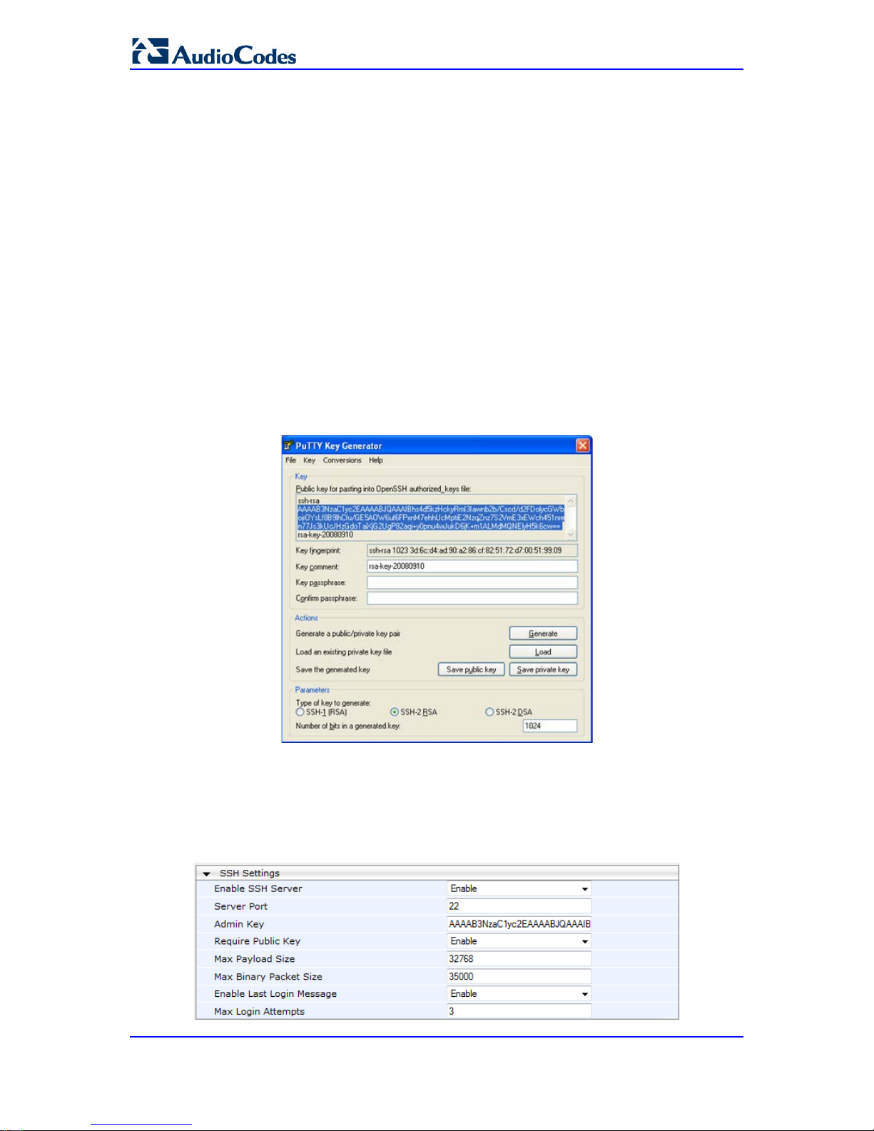
User's Manual 74 Document #: LTRT-65422
MP-11x & MP-124
PuTTY, which can be downloaded from
http://www.chiark.greenend.org.uk/~sgtatham/putty/.
By default, SSH uses the same username and password as the Telnet and Web server.
SSH supports 1024/2048-bit RSA public keys, providing carrier-grade security. Follow the
instructions below to configure the device with an administrator RSA key as a means of
strong authentication.
To enable SSH and configure RSA public keys for Windows (using PuTTY SSH):
1. Start the PuTTY Key Generator program, and then do the following:
a. Under the 'Parameters' group, do the following:
♦ Select the SSH-2 RSA option.
♦ In the 'Number of bits in a generated key ' field, enter "1024" bits.
b. Under the 'Actions' group, click Generate and then follow the on-screen
instructions.
c. Under the 'Actions' group, click Save private key to save the new private key to a
file (*.ppk) on your PC.
d. Under the 'Key' group, select the displayed encoded text between "ssh-rsa" and
"rsa-key-….", as shown in the example below:
Figure 5-2: Selecting Public RSA Key in PuTTY
2. Open the Telnet/SSH Settings page (Configuration tab > System menu >
Management > Telnet/SSH Settings), and then do the following:
a. Set the 'Enable SSH Server' parameter to Enable.
b. Paste the public key that you copied in Step 1.d int o the 'Admin Key' field, as
shown below:
Figure 5-3: SSH Settings - Pasting Public RSA Key in 'Admin Key' Field
Page 75

Version 6.6 75 MP-11x & MP-124
User's Manual 5. CLI-Based Management
c. For additional security, you can set the 'Require Public Key' to Enable. This
ensures that SSH access is only possible by using the RSA key and not by using
user name and password.
d. Configure the other SSH parameters as required. For a description of these
parameters, see SSH Parameters on page 453.
e. Click Submit.
3. Start the PuTTY Configuration program, and then do the following:
a. In the 'Category' tree, drill down to Connection, then SSH, and then Auth; the
'Options controlling SSH authentication' pane appears.
b. Under the 'Authentication parameters' group, click Browse and then locate the
private key file that you created and saved in Step 4.
4. Connect to the device with SSH using the username "Admin"; RSA key negotiation
occurs automatically and no password is required.
To configure RSA public keys for Linux (using OpenSSH 4.3):
1. Run the following command to create a new key in the admin.key file and to save the
public portion to the admin.key.pub file:
ssh-keygen -f admin.key -N "" -b 1024
2. Open the admin.key.pub file, and then copy the encoded string from "ssh-rsa" to the
white space.
3. Open the Telnet/SSH Settings page (Configuration tab > System menu >
Management > Telnet/SSH Settings), and then paste the value copied in Step 2 into
the 'Admin Key' field.
4. Click Submit.
5. Connect to the device with SSH, using the following command:
ssh -i admin.key xx.xx.xx.xx
where xx.xx.xx.xx is the device's IP address. RSA-key negotiation occurs
automatically and no password is required.
5.3 Establishing a CLI Session
The procedure below describes how to establish a CLI session with the device.
Notes:
• The default login username and password are both "Admin" (case-
sensitive).
• Only the primary User Account, which has Security Administration
access level (200) can access the device using Telne t. For configuring
the username and password, see Configuring Web User Accounts on
page 62.
To establish a CLI session with the device:
1. Establish a Telnet or SSH session with the device using its OAMP IP address.
2. Log in to the session using the username and password assigned to the Admin user of
the Web interface.
3. At the login prompt, type the username, and then press Enter:
login: Admin
Page 76

User's Manual 76 Document #: LTRT-65422
MP-11x & MP-124
4. At the password prompt, type the password, and then press Enter:
password: Admin
After logging in, the current directory (root), available commands, available
subdirectories, and a welcome message are displayed at the CLI prompt:
login: Admin
password:
ready. Type "exit" to close the connection.
SIP/ SECurity/ DebugRecording/ MGmt/ ControlProtocol/ CONFiguration/
IPNetworking/ TPApp/ BSP/
PING SHow
/>
5.4 CLI Commands
The CLI commands are used mainly to display current configuration and performance.
These commands are organized in subdirectories. When the CLI session starts, you are
located in the 'root' directory.
To access a subdirectory, type its name, and then press Enter. The CLI commands can be
entered in an abbreviated format by typing only the letters shown in upper case (i.e., capital
letters). For example, the CHangePassWord command can be entered by typing chpw. If
you know the full path to a command inside one of the subdirectories, the short format can
be used to run it directly. For example, the PERFormance command in the MGmt
subdirectory may be run directly by typing /mg/perf.
The following table summarizes the basic CLI comm ands:
Basic CLI Commands
Purpose Commands Description
Help
h
Displays the help for a specific command, acti on, or parameter.
Navigation
cd
Enters another directory.
cd root
Navigates to the root directory (/).
..
Goes up one level.
exit
Terminates the CLI session.
5.4.1 Status Commands
The following table summarizes the Show commands and their corresponding options.
Show CLI Commands
Command Short Format Arguments Description
SHow
sh info | dsp | ip |
log
Displays operational data.
info: Displays general device information
dsp: Displays DSP resource information
ip: Displays information about IP interfaces
SHow INFO
sh info - Displays device hard ware information,
versions, uptime, temperature reading, and the
last reset reason.
Page 77

Version 6.6 77 MP-11x & MP-124
User's Manual 5. CLI-Based Management
Command Short Format Arguments Description
SHow DSP
sh dsp status | perf Displays status and version for each DSP
device, along with overall performance
statistics.
SHow IP
sh ip conf | perf |
route
Displays IP interface status and configuration,
along with performance statistics.
Note: The display format may change
according to the configuration.
SHow LOG
sh log [stop]
Displays (or stops displaying) Syslog messages
in the CLI session.
Example:
/>sh info
Board type: gateway SDH, firmware version 6.60.000.020
Uptime: 0 days, 0 hours, 3 minutes, 54 seconds
Memory usage: 63%
Temperature reading: 39 C
Last reset reason:
Board was restarted due to issuing of a reset from Web interface
Reset Time : 7.1.2012 21.51.13
/>sh dsp status
DSP firmware: 491096AE8 Version:0660.03 Use d=0 Free=480 Total=480
DSP device 0: Active Used=16 Free= 0 Total=16
DSP device 1: Active Used=16 Free= 0 Total=16
DSP device 2: Active Used=16 Free= 0 Total=16
DSP device 3: Active Used=16 Free= 0 Total=16
DSP device 4: Active Used=16 Free= 0 Total=16
DSP device 5: Active Used=16 Free= 0 Total=16
DSP device 6: Inactive
DSP device 7: Inactive
DSP device 8: Inactive
DSP device 9: Inactive
DSP device 10: Inactive
DSP device 11: Inactive
DSP device 12: Active Used=16 Free= 0 Total=16
DSP device 13: Active Used=16 Free= 0 Total=16
DSP device 14: Active Used=16 Free= 0 Total=16
DSP device 15: Active Used=16 Free= 0 Total=16
DSP device 16: Active Used=16 Free= 0 Total=16
DSP device 17: Active Used=16 Free= 0 Total=16
DSP device 18: Inactive
PSEC - DSP firmware: AC491IPSEC Version: 0660.03
CONFERENCE - DSP firmware: AC49 1256C Version: 0660.03
/>sh dsp perf
DSP Statistics (statistics for 968 seconds):
Active DSP resources: 480
Total DSP resources: 480
DSP usage %: 100
/>sh ip perf
Networking Statistics (statistics for 979 seconds):
IP KBytes TX: 25
IP KBytes RX: 330
IP KBytes TX per second: 0
IP KBytes RX per second: 1
Page 78

User's Manual 78 Document #: LTRT-65422
MP-11x & MP-124
IP Packets TX: 1171
IP Packets RX: 5273
IP Packets TX per second: 3
IP Packets RX per second: 12
Peak KByte/s TX in this interval: 18
Peak KByte/s RX in this interval: 4
Discarded packets: 186
DHCP requests sent: 0
IPSec Security Associations: 0
/>/mg/perf reset
Done.
/>sh ip perf
Networking Statistics (statistics for 2 seconds):
IP KBytes TX: 2
IP KBytes RX: 4
IP KBytes TX per second: 0
IP KBytes RX per second: 1
IP Packets TX: 24
IP Packets RX: 71
IP Packets TX per second: 3
IP Packets RX per second: 12
Peak KByte/s TX in this interval: 18
Peak KByte/s RX in this interval: 4
Discarded packets: 0
DHCP requests sent: 0
IPSec Security Associations: 0
/>sh ip conf
Interface IP Address Subnet Mask Default Gateway
--------- ------------------ -------------- --------- OAM 10.4.64.13 55.255.0.0 10.4.0.1
Media 10.4.64.13 255.255.0.0 10.4.0.1
Control 10.4.64.13 255.255.0.0 10.4.0.1
MAC address: 00-90-8f-04-5c-e9
/>sh ip route
Destination Mask Gateway Intf Flags
------------- ---------------- ------------------------
0.0.0.0 0.0.0.0 10.4.0.1 OAM A S
10.4.0.0 255.255.0.0 10.4.64.13 OAM A L
127.0.0.0 255.0.0.0 127.0.0.1 AR S
127.0.0.1 255.255.255.255 127.0.0.1 A L H
Flag legend: A=Active R=Reject L=Local S=Static E=rEdirect
M=Multicast
B=Broadcast H=Host I=Invalid
End of routing table, 4 entries displayed.
5.5 Ping Command
The Ping command is described in the following table:
Ping Command
Command Short Format Arguments Description
PING ping
[-n count]
[-l size]
[-w timeout]
[-p cos]
Sends ICMP echo request packets to a
specified IP address.
count: number of packets to send.
size: payload size in each packet.
timeout: time (in seconds) to wait for a reply
Page 79

Version 6.6 79 MP-11x & MP-124
User's Manual 5. CLI-Based Management
Command Short Format Arguments Description
ip-address
to each packet.
cos: Class-of-Service (as per 802.1p) to
use.
Example:
/>ping 10.31.2.10
Ping process started for address 10.31.2.10. Process ID - 27.
Reply from 10.31.2.10: bytes=0 time<0ms
Reply from 10.31.2.10: bytes=0 time<0ms
Reply from 10.31.2.10: bytes=0 time<0ms
Reply from 10.31.2.10: bytes=0 time<0ms
Ping statistics for 10.31.2.10:
Packets:Sent = 4, Received = 4, Lost 0 (0% loss),
Approximate round trip times in milli-seconds:
Minimum = 0ms, Maximum = 0ms, Average = 0ms
5.6 Management Commands
The commands under the MGmt directory, described in the table below, display current
performance values.
CLI Management Command
Command Short Format Arguments Description
/MGmt/PERFormance
/mg/perf basic | control | dsp |
net | reset
Displays performance statistics.
The reset argument clears all
statistics to zero.
5.7 Configuration Commands
The commands under the CONFiguration directory query and modify the current device
configuration. The following commands are available:
Configuration CLI Commands
Command Short
Format
Arguments Description
SetConfigParam IP
/conf/scp ip ip-addr subnet def-
gw
Sets the IP address, subnet mask,
and default gateway address of the
device (on-the-fly).
Note: This command may cause
disruption of service. The CLI session
may disconnect since the device
changes its IP address.
RestoreFactorySettings
/conf/rfs
Restores all parameters to factory
settings.
SaveAndRestart
/conf/sar
Saves all current configurations to the
non-volatile memory and resets the
device.
Page 80

User's Manual 80 Document #: LTRT-65422
MP-11x & MP-124
Command Short
Format
Arguments Description
ConfigFile
/conf/cf view | get | set Retrieves the full ini file from the
device and allows loading a new ini
file directly in the CLI session.
Note: The argument view displays the
file, page by page. The argument get
displays the file without breaks.
Page 81

Version 6.6 81 MP-11x & MP-124
User's Manual 6. SNMP-Based Management
6 SNMP-Based Management
The device provides an embedded SNMP Agent to operate with a third-party SNMP
Manager (e.g., element management system or EMS) for operation, administration,
maintenance, and provisioning (OAMP) of the device. The SNMP Agent supports standard
Management Information Base (MIBs) and proprietary MIBs, enabling a deeper probe into
the interworking of the device. The SNMP Agent can also send unsolicited events (SNMP
traps) towards the SNMP Manager. All supported MIB files are supplied to customers as
part of the release.
This section provides configuration relating to SNMP management.
Note: For more information on SNMP support such as SNMP traps, refer to the
SNMP User's Guide.
6.1 Configuring SNMP Community Strings
The SNMP Community String page allows you to configure up to five read-only and up to
five read-write SNMP community strings and to configure the community string that is used
for sending traps.
For detailed descriptions of the SNMP parameters, see 'SNMP Parameters' on page 435.
To configure the SNMP community strings:
1. Open the SNMP Community String page (Configuration tab > System menu >
Management submenu > SNMP submenu > SNMP Community String).
2. Configure the SNMP community strings parameters according to the table below.
3. Click Submit to apply your changes.
4. To save the changes to flash memory, see 'Saving Configuration' on page 324.
Page 82

User's Manual 82 Document #: LTRT-65422
MP-11x & MP-124
To delete a community string, select the Delete check box corresponding to the community
string that you want to delete, and then click Submit.
Table 6-1: SNMP Community String Parameters Description
Parameter Description
Community String
Read Only [SNMPReadOnlyCommunityString_x]: Up to five
read-only community strings (up to 19 characte rs each). The
default string is 'public'.
Read / Write [SNMPReadWriteCommunityString_x]: Up to
five read / write community strings (up to 19 characters each).
The default string is 'private'.
Trap Community String
[SNMPTrapCommunityString]
Community string used in traps (up to 19 characters).
The default string is 'trapuser'.
6.2 Configuring SNMP Trap Destinations
The SNMP Trap Destinations page allows you to configure up to five SNMP trap
managers. You can associate a trap destination with SNMPv2 users and specific SNMPv3
users. Associating a trap destination with SNMPv3 users sends encrypted and
authenticated traps to the SNMPv3 destination. By default, traps are sent unencrypted
using SNMPv2.
To configure SNMP trap destinations:
1. Open the SNMP Trap Destinations page (Configuration tab > System menu >
Management submenu > SNMP > SNMP Trap Destinations).
Figure 6-1: SNMP Trap Destinations Page
2. Configure the SNMP trap manager parameters according to the table below.
3. Select the check box corresponding to the SNMP Manager that you wish to enable.
4. Click Submit to apply your changes.
Note: Only row entries whose corresponding check boxes are selected are applied
when clicking Submit; otherwise, settings revert to their def aul ts.
Page 83

Version 6.6 83 MP-11x & MP-124
User's Manual 6. SNMP-Based Management
Table 6-2: SNMP Trap Destinations Parameters Description
Parameter Description
Web: SNMP Manager
[SNMPManagerIsUsed_x]
Enables the SNMP Manager to receive traps and checks
the validity of the configured destination (IP address and
port number).
[0] (check box cleared) = (Default) Disables SNMP
Manager
[1] (check box selected) = Enables SNMP Manager
Web: IP Address
[SNMPManagerTableIP_x]
Defines the IP address (in dotted-decimal notation, e.g.,
108.10.1.255) of the remote host used as the SNMP
Manager. The device sends SNMP traps to this IP
address.
Trap Port
[SNMPManagerTrapPort_x]
Defines the port number of the remote SNMP M anager.
The device sends SNMP traps to this port.
The valid value range is 100 to 4000. The default is 162.
Web: Trap User
[SNMPManagerTrapUser]
Associates a trap user with the trap destination. This
determines the trap format, authenticatio n level, and
encryption level.
v2cParams (default) = SNMPv2 user community string
SNMPv3 user configured in 'Configuring SNMP V3
Users' on page 84
Trap Enable
[SNMPManagerTrapSendingEnable_x]
Activates the sending of traps to the SNMP Manager.
[0] Disable
[1] Enable (Default)
6.3 Configuring SNMP Trusted Managers
The SNMP Trusted Managers page allows you to configure up to five SNMP Trusted
Managers, based on IP addresses. By default, the SNMP agent accepts SNMP Get and
Set requests from any IP address, as long as the correct community string is used in the
request. Security can be enhanced by using Trusted Managers, which is an IP address
from which the SNMP agent accepts and processes SNMP requests.
Notes: The SNMP Trusted Managers table can also be configured using the table ini
file parameter, SNMPTrustedMgr_x (see 'SNMP Parameters' on page 435).
Page 84

User's Manual 84 Document #: LTRT-65422
MP-11x & MP-124
To configure SNMP Trusted Managers:
1. Open the SNMP Trusted Managers page (Configuration tab > System menu >
Management submenu > SNMP submenu > SNMP Trusted Managers).
Figure 6-2: SNMP Trusted Managers
2. Select the check box corresponding to the SNMP Trusted Manager that you want to
enable and for whom you want to define an IP address.
3. Define an IP address in dotted-decimal notation.
4. Click Submit to apply your changes.
5. To save the changes, see 'Saving Configuration' on page 324.
6.4 Configuring SNMP V3 Users
The SNMP v3 Users page allows you to configure authentication and privacy for up to 10
SNMP v3 users.
To configure SNMP v3 users:
1. Open the SNMP v3 Users page (Configuration tab > System menu > Management
submenu > SNMP submenu > SNMP V3 Users).
2. Click Add; the following dialog box appears:
Figure 6-3: SNMP V3 Setting Page - Add Record Dialog Box
3. Configure the SNMP V3 Setting parameters according to the table below.
4. Click Submit to apply your settings.
5. To save the changes, see 'Saving Configuration' on page 324.
Page 85

Version 6.6 85 MP-11x & MP-124
User's Manual 6. SNMP-Based Management
Notes:
• If you delete a user that is associated with a trap destination (in
'Configuring SNMP Trap Destinations' on page 82), the configured trap
destination becomes disabled and the trap user rev erts to default (i.e.,
SNMPv2).
• The SNMP v3 Users table can also be configured using t he table ini file
parameter, SNMPUsers (see 'SNMP Parameters' on page 435).
Table 6-3: SNMP V3 Users Parameters
Parameter Description
Index
[SNMPUsers_Index]
The table index.
The valid range is 0 to 9.
User Name
[SNMPUsers_Username]
Name of the SNMP v3 user. This name must be unique.
Authentication Protocol
[SNMPUsers_AuthProtocol]
Authentication protocol of the SNMP v3 user.
[0] None (default)
[1] MD5
[2] SHA-1
Privacy Protocol
[SNMPUsers_PrivProtocol]
Privacy protocol of the SNMP v3 user.
[0] None (default)
[1] DES
[2] 3DES
[3] AES-128
[4] AES-192
[5] AES-256
Authentication Key
[SNMPUsers_AuthKey]
Authentication key. Keys can be entered in the form of a text
password or long hex string. Keys are always persisted as long hex
strings and keys are localized.
Privacy Key
[SNMPUsers_PrivKey]
Privacy key. Keys can be entered in the form of a text password or
long hex string. Keys are always persisted as long hex strings and
keys are localized.
Group
[SNMPUsers_Group]
The group with which the SNMP v3 user is associated.
[0] Read-Only (default)
[1] Read-Write
[2] Trap
Note: All groups can be used to send traps.
Page 86

User's Manual 86 Document #: LTRT-65422
MP-11x & MP-124
Reader's Notes
Page 87

Version 6.6 87 MP-11x & MP-124
User's Manual 7. EMS-Based Management
7 EMS-Based Management
AudioCodes Element Management System (EMS) is an advanced solution for standardsbased management of gateways within VoP networks, covering all areas vital for the
efficient operation, administration, management and provisioning (OAM&P) of AudioCodes'
families of gateways. The EMS enables Network Equipment Providers (NEPs) and System
Integrators (SIs) the ability to offer customers rapid time-to-market and inclusive, costeffective management of next-generation networks. The standards-compliant EMS uses
distributed SNMP-based management software, optimized to support day-to-day Network
Operation Center (NOC) activities, offering a feature-rich management framework. It
supports fault management, configuration and security.
Note: For more information on using the EMS tool, refer to the EMS User's Manual
and EMS Server IOM Manual.
Page 88

User's Manual 88 Document #: LTRT-65422
MP-11x & MP-124
Reader's Notes
Page 89

Version 6.6 89 MP-11x & MP-124
User's Manual 8. INI File-Based Management
8 INI File-Based Management
The device can be configured using an ini file, which is a text-based file with an ini file
extension name that can be created using any standard text-based editor such as
Notepad. Each configuration element of the device has a corresponding ini file parameter
that you can use in the ini file for configuring the device. When you have created the ini file
with your ini file parameter settings, you apply these settings to the device by installing
(loading) the ini file to the device.
Notes:
• For a list and description of the ini file parameters, see 'Configuration
Parameters Reference' on page 421.
• To restore the device to default settings using the ini file, see 'Restoring
Factory Defaults' on page 347.
8.1 INI File Format
The ini file can be configured with any number of parameters. These ini file parameters can
be one of the following types:
Individual parameters - see 'Configuring Individual ini File Parameters' on page 89
Table parameters - see 'Configuring Table ini File Parameters' on page 89
8.1.1 Configuring Individual ini File Parameters
The syntax for configuring individual ini file parameters in the ini file is as follows:
An optional, subsection name (or group name) enclosed in square brackets "[...]". This
is used to conveniently group similar parameter s by their functionality.
Parameter name, followed by an equal "=" sign and then its value.
Comments must be preceded by a semicolon ";".
[subsection name]
parameter name = value
parameter name = value
; this is a comment line
; for example:
[System Parameters]
SyslogServerIP = 10.13.2.69
EnableSyslog = 1
For general ini file formatting rules, see 'General ini File Form atting Rules' on page 91.
8.1.2 Configuring Table ini File Parameters
The table ini file parameters allow you to configure tables, which include multiple
parameters (columns) and row entries (indices). When loading an ini file to the device, it's
recommended to include only tables that belong to applications that are to be configured
(dynamic tables of other applications are empt y, but static tables are not).
The table ini file parameter is composed of the foll owing elements:
Title of the table: The name of the table in square brackets, e.g.,
[MY_TABLE_NAME].
Format line: Specifies the columns of the table (by their string names) that are to be
Page 90

User's Manual 90 Document #: LTRT-65422
MP-11x & MP-124
configured.
• The first word of the Format line must be "FORM A T " , followed by the Index field
name and then an equal "=" sign. After the equal sign, the names of the columns
are listed.
• Columns must be separated by a comma ",".
• The Format line must only include columns that can be modified (i.e., parameters
that are not specified as read-only). An exception is Index fields, which are
mandatory.
• The Format line must end with a semicolon ";".
Data line(s): Contain the actual values of the columns (parameters). The values are
interpreted according to the Format line.
• The first word of the Data line must be the table’s string name followed by the
Index field.
• Columns must be separated by a comma ",".
• A Data line must end with a semicolon ";".
End-of-Table Mark: Indicates the end of the table. The same string used for the
table’s title, preceded by a backslash "\", e.g., [\MY_TABLE_NAME].
The following displays an example of the structure of a table ini file parameter.
[Table_Title]
; This is the title of the table.
FORMAT Index = Column_Name1, Column_Name2, Column_Name3;
; This is the Format line.
Index 0 = value1, value2, value3;
Index 1 = value1, $$, value3;
; These are the Data lines.
[\Table_Title]
; This is the end-of-the-table-mark.
The table ini file parameter formatting rules are listed below:
Indices (in both the Format and the Data lines) must appear in the same order. The
Index field must never be omitted.
The Format line can include a subset of the configurable fields in a table. In this case,
all other fields are assigned with the pre-defined default values for each configured
line.
The order of the fields in the Format line isn’t significant (as opposed to the I ndex
fields). The fields in the Data lines are interpreted according to the order specified in
the Format line.
The double dollar sign ($$) in a Data line indicates the default value for the para m eter.
The order of the Data lines is insignificant.
Data lines must match the Format line, i.e., it must contain exactly the sam e number
of Indices and Data fields and must be in exactly the same order.
A row in a table is identified by its table name and Index field. Each such row ma y
appear only once in the ini file.
Table dependencies: Certain tables may depend on other tables. For example, one
table may include a field that specifies an entry i n another table. This method is used
to specify additional attributes of an entity, or to specify that a given entity is part of a
larger entity. The tables must appear in the order of their dependency (i.e., if Table X
is referred to by Table Y, Table X must appear in the ini file before Table Y).
For general ini file formatting rules, see 'General ini File Form atting Rules' on page 91.
The table below displays an example of a table ini fil e parameter:
[ CodersGroup0 ]
FORMAT CodersGroup0_Index = CodersGroup0_Name, CodersGroup0_pTime,
CodersGroup0_rate, CodersGroup0_PayloadType, CodersGroup0_Sce;
Page 91

Version 6.6 91 MP-11x & MP-124
User's Manual 8. INI File-Based Management
CodersGroup0 0 = g711Alaw64k, 20, 0, 255, 0;
CodersGroup0 1 = eg711Ulaw, 10, 0, 71, 0;
[ \CodersGroup0 ]
Note: Do not include read-only parameters in the table ini file parameter as this can
cause an error when attempting to load the file t o the device.
8.1.3 General ini File Formatting Rules
The ini file must adhere to the following formatting rules:
The ini file name must not include hyphens "-" or spaces; if necessary, use an
underscore "_" instead.
Lines beginning with a semi-colon ";" are ignored. These can be used for adding
remarks in the ini file.
A carriage return (i.e., Enter) must be done at the end of each line.
The number of spaces before and after the equals sign "=" is irrelevant.
Subsection names for grouping parameters are optional.
If there is a syntax error in the parameter name, the value is ignored.
Syntax errors in the parameter's value can cause unexpected errors (parameters may
be set to the incorrect values).
Parameter string values that denote file names (e.g., CallProgressTonesFileName)
must be enclosed with inverted commas, e.g., Cal lProgressTonesFileName =
'cpt_usa.dat'.
The parameter name is not case-sensitive.
The parameter value is not case-sensitive, except for coder names.
The ini file must end with at least one carriage return.
8.2 Loading an ini File
You can load an ini file to the device using the following met hods:
Web interface, using any of the following pages:
• Configuration File - see 'Backing Up and Loading Co nfiguration File' on page 346
• Load Auxiliary Files - see 'Loading Auxiliary Files' on page 327
AudioCodes AcBootP utility, which uses Bootstrap Protocol (BootP) and acts as a
TFTP server. For information on using the AcBootP utility, refer to AcBootP Utility
User's Guide.
Any standard TFTP server. This is done by storing the ini file on a TFTP server and
then having the device download the file from it.
When loaded to the device, the configuration settings of the ini file are saved to the
device's non-volatile memory. If a parameter is not included in the loaded ini file, the
following occurs:
Using the Load Auxiliary Files page: Current settings for parameters that were not
included in the loaded ini file are retained.
All other methods: The default is assigned to the parameters that were not included in
the loaded ini file and thereby, overriding v alues previously configured for these
parameters.
Page 92

User's Manual 92 Document #: LTRT-65422
MP-11x & MP-124
Notes:
• For a list and description of the ini file parameters, see 'Configuration
Parameters Reference' on page 421.
• Some parameters are configurable only throug h the ini file (and not the
Web interface).
• To restore the device to default settings using the ini file, see 'Restoring
Factory Defaults' on page 347.
8.3 Modifying an ini File
You can modify an ini file currently used by the device. Modifying an ini file instead of
loading an entirely new ini file preserves the device's current configuration.
To modify an ini file:
1. Save the device's configuration as an ini file on your computer, using the Web
interface (see 'Loading an ini File' on page 91).
2. Open the ini file using a text file editor such as Notepad, and then modify the ini file
parameters as required.
3. Save the modified ini file, and then close the file.
4. Load the modified ini file to the device (see 'Loading an ini File' on page 91).
Tip: Before loading the ini file to the device, verify that the file extension of the file
is .ini.
8.4 Secured Encoded ini File
The ini file contains sensitive information that is required for the functioning of the device.
The file may be loaded to the device using TFTP or HTTP. These protocols are not secure
and are vulnerable to potential hackers. To overcome this security threat, the AudioCodes
DConvert utility allows you to binary-encode (encrypt) the ini file before loading it to the
device. For more information, refer to DConvert Ut i l ity User's Guide.
Notes:
• The procedure for loading an encoded ini file is identical to the procedure
for loading an unencoded ini file (see 'Loading an ini File' on page 91).
• If you download from the device (to a folder on your computer) an ini file
that was loaded encoded to the device, the file i s saved as a regular ini
file (i.e., unencoded).
Page 93

Part III
General System Settings
Page 94

Page 95
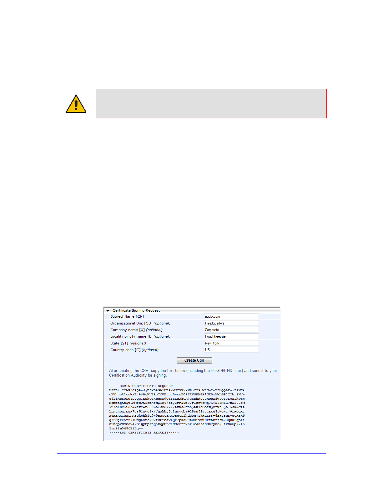
Version 6.6 95 MP-11x & MP-124
User's Manual 9. Configuring Certificates
9 Configuring Certificates
The Certificates page allows you to configure X.509 certificates, which are used for secure
management of the device, secure SIP transactio ns, and other security applications.
Note: The device is shipped with an active TLS setup. Thus, configure certificates
only if required.
9.1 Replacing the Device's Certificate
The device is supplied with a working TLS configuration consisting of a unique self-signed
server certificate. If an organizational Public Key Infrastructure (PKI) is used, you may wish
to replace this certificate with one provided by your security administrator.
To replace the device's certificate:
1. Your network administrator should allocate a unique DNS name for the device (e.g.,
dns_name.corp.customer.com). This DNS name is used to access the device and
therefore, must be listed in the server certi ficate.
2. If the device is operating in HTTPS mode, then set the 'Secured Web Connection
(HTTPS)' parameter (HTTPSOnly) to HTTP and HTTPS (see 'Configuring Web
Security Settings' on page 69). This ensures that you have a method for accessing the
device in case the new certificate does not work. Restore the previous setting after
testing the configuration.
3. Open the Certificates page (Configuration tab > System menu > Certificates).
4. Under the Certificate Signing Request group, do the following:
a. In the 'Subject Name [CN]' field, enter the DNS name.
b. Fill in the rest of the request fields according to y our security provider's
instructions.
c. Click the Create CSR button; a textual certificate signing request is displayed in
the area below the button:
Figure 9-1: Certificate Signing Request Group
Page 96

User's Manual 96 Document #: LTRT-65422
MP-11x & MP-124
5. Copy the text and send it to your security provider. The security provider, also known
as Certification Authority or CA, signs this request and then sends you a server
certificate for the device.
6. Save the certificate to a file (e.g., cert.txt). Ensure that the file is a plain-text file
containing the"‘BEGIN CERTIFICATE" header, as shown in the example of a Base64Encoded X.509 Certificate below:
-----BEGIN CERTIFICATE-----
MIIDkzCCAnugAwIBAgIEAgAAADANBgkqhkiG9w0BAQQFADA/MQswCQYDVQQGEw
JGUjETMBEGA1UEChMKQ2VydGlwb3N0ZTEbMBkGA1UEAxMSQ2VydGlwb3N0ZSBT
ZXJ2ZXVyMB4XDTk4MDYyNDA4MDAwMFoXDTE4MDYyNDA4MDAwMFowPzELMAkGA1
UEBhMCRlIxEzARBgNVBAoTCkNlcnRpcG9zdGUxGzAZBgNVBAMTEkNlcnRpcG9z
dGUgU2VydmV1cjCCASEwDQYJKoZIhvcNAQEBBQADggEOADCCAQkCggEAPqd4Mz
iR4spWldGRx8bQrhZkonWnNm`+Yhb7+4Q67ecf1janH7GcN/SXsfx7jJpreWUL
f7v7Cvpr4R7qIJcmdHIntmf7JPM5n6cDBv17uSW63er7NkVnMFHwK1QaGFLMyb
FkzaeGrvFm4k3lRefiXDmuOe+FhJgHYezYHf44LvPRPwhSrzi9+Aq3o8pWDguJ
uZDIUP1F1jMa+LPwvREXfFcUW+w==
-----END CERTIFICATE-----
7. Scroll down to the Upload certificates files from your computer group, click the
Browse button corresponding to the 'Send Device Certificate...' field, navigate to the
cert.txt file, and then click Send File.
8. After the certificate successfully loads to the device, save the configuration with a
device reset (see 'Saving Configuration' on page 324); the Web interface uses the
provided certificate.
9. Open the Certificates page again and verify that under the Certificate information
group (at the top of the page), the 'Private key' read-only field displays "OK";
otherwise, consult your security administrat or:
Figure 9-2: Private key "OK" in Certificate Information Group
10. If the device was originally operating in HTTPS mode and you disabled it in Step 2,
then return it to HTTPS by setting the 'Secured Web Connection (HTTPS)' parameter
to HTTPS Only, and then reset the device with a flash burn.
Notes:
• The certificate replacement process can be repe ated when necessary
(e.g., the new certificate expires).
• It is possible to use the IP address of the device (e.g., 10.3.3.1) instead
of a qualified DNS name in the Subject Name. Thi s i s not recommended
since the IP address is subject to change and may not uni quely identify
the device.
• The device certificate can also be loaded via t he A utomatic Update
Facility by using the HTTPSCertFileName ini file par am eter.
9.2 Loading a Private Key
The device is shipped with a self-generated random private key, which cannot be extracted
from the device. However, some security administrators require that the private key be
generated externally at a secure facility and then loaded to the device through
configuration. Since private keys are sensitive security parameters, take precautions to
Page 97

Version 6.6 97 MP-11x & MP-124
User's Manual 9. Configuring Certificates
load them over a physically-secure connection such as a back-to-back Ethernet cable
connected directly to the managing computer.
To replace the device's private key:
1. Your security administrator should provide you with a private key in either textual PEM
(PKCS #7) or PFX (PKCS #12) format. The file may be encrypted with a short passphrase, which should be provided by your security administrator.
2. If the device is operating in HTTPS mode, then set the 'Secured Web Connection
(HTTPS)' field (HTTPSOnly) to HTTP and HTTPS (see 'Configuring Web Security
Settings' on page 69). This ensures that you have a method for accessing the device
in case the new configuration does not work. Restore the previous setting after testing
the configuration.
3. Open the Certificates page (Configuration tab > System menu > Certificates) and
scroll down to the Upload certificate files from your computer group.
Figure 9-3: Upload Certificate Files from your Computer Group
4. Fill in the 'Private key pass-phrase' field, if required.
5. Click the Browse button corresponding to the 'Send Private Key' field, navigate to the
key file, and then click Send File.
6. If the security administrator has provided you with a device certificate file, load it using
the 'Send Device Certificate' field.
7. After the files successfully load to the device, save the configuration with a device
reset (see 'Saving Configuration' on page 324); the Web interface uses the new
configuration.
8. Open the Certificates page again, and verify that under the Certificate information
group (at the top of the page) the 'Private key' read-only field displays "OK"; otherwise,
consult your security administrator.
9. If the device was originally operating in HTTPS mode and you disabled it in Step 2,
then enable it by setting the 'Secured Web Connection (HTTPS)' field to HTTPS Only.
Page 98

User's Manual 98 Document #: LTRT-65422
MP-11x & MP-124
9.3 Mutual TLS Authentication
By default, servers using TLS provide one-way authentication. The client is certain that the
identity of the server is authentic. When an organizational PKI is used, two-way
authentication may be desired - both client and server should be authenticated using X.509
certificates. This is achieved by installing a client certificate on the managing PC and
loading the root CA's certificate to the device's Trusted Root Certificate Store. The Trusted
Root Certificate file may contain more than one CA certificate combined, using a text
editor.
Since X.509 certificates have an expiration date and time, the device must be configured to
use NTP (see 'Simple Network Time Protocol Support' on page 101) to obtain the current
date and time. Without the correct date and time, client certificates cannot work.
To enable mutual TLS authentication for HTTPS:
1. Set the 'Secured Web Connection (HTTPS)' field to HTTPS Only (see 'Configuring
Web Security Settings' on page 69) to ensure you have a method for accessing the
device in case the client certificate does not work. Restore the previous setting after
testing the configuration.
2. Open the Certificates page (see 'Replacing the Device's Certificate' on page 95).
3. In the Upload certificate files from your computer group, click the Browse button
corresponding to the 'Send Trusted Root Certificate Store ...' field, navigate to the file,
and then click Send File.
4. When the operation is complete, set the 'Requires Client Certificates for HTTPS
connection' field to Enable (see 'Configuring Web Security Settings' on page 69).
5. Save the configuration with a device reset (see 'Saving Configuration' on page 324).
When a user connects to the secured Web interfac e of the device:
If the user has a client certificate from a CA that is listed in the Trusted Root Certificate
file, the connection is accepted and the user is prompted for the system password.
If both the CA certificate and the client certificate appear in the Trusted Root
Certificate file, the user is not prompted for a password (thus, providing a single-signon experience - the authentication is performe d using the X.509 digital signature).
If the user does not have a client certificate from a listed CA or does not have a client
certificate, the connection is rejected.
Notes:
• The process of installing a client certificat e on your PC is beyond the
scope of this document. For more information, refer to your operating
system documentation, and/or consult your securi ty administrator.
• The root certificate can also be loaded via the Autom atic Update facility,
using the HTTPSRootFileName ini file parameter.
• You can enable the device to check whether a peer's certificate ha s been
revoked by an Online Certificate Status Prot ocol (OCSP) server (see
Configuring Certificate Revocation Checking (OCSP) on page 99.
Page 99

Version 6.6 99 MP-11x & MP-124
User's Manual 9. Configuring Certificates
9.4 Self-Signed Certificates
The device is shipped with an operational, self-signed server certificate. The subject name
for this default certificate is 'ACL_nnnnnnn', where nnnnnnn denotes the serial number of
the device. However, this subject name may not be appropriate for production and can be
changed while still using self-signed certificates.
To change the subject name and regenerate the self-signed certificate:
1. Before you begin, ensure the following:
• You have a unique DNS name for the device (e.g.,
dns_name.corp.customer.com). This nam e i s used to access the device and
should therefore, be listed in the server certificate.
• No traffic is running on the device. The certificat e generation process is disruptive
to traffic and should be executed during maint enance time.
2. Open the Certificates page (see 'Replacing the Device's Certificate' on page 95).
3. In the 'Subject Name [CN]' field, enter the fully-qualified DNS name (FQDN) as the
certificate subject, select the desired private key size (in bits), and then click Generate
self-signed; after a few seconds, a message appears displaying the new subject
name.
4. Save the configuration with a device reset (see 'Saving Configuration' on page 324)
for the new certificate to take effect.
9.5 TLS Server Certificate Expiry Check
The device can periodically check the validation date of the installed TLS server certificate.
This periodic check interval is user-defined. In addition, within a user-defined number of
days before the installed TLS server certificate expires, the device can be configured to
send the SNMP trap, acCertificateExpiryNotifiaction to notify of the impending certificate
expiration.
To configure TLS certificate expiry checks and notification:
1. Open the Certificates page (see 'Replacing the Device's Certificate' on page 95).
2. In the 'TLS Expiry Check Start' field, enter the number of days before the installed TLS
server certificate is to expire at which the devi ce must send a trap to notify of this.
Figure 9-4: TLS Expiry Settings Group
3. In the 'TLS Expiry Check Period' field, enter the periodical interval (in days) for
checking the TLS server certificate expiry date. By default, the device checks the
certificate every 7 days.
4. Click the Submit TLS Expiry Settings button.
9.6 Configuring Certificate Revocation Checking (OCSP)
Some Public-Key Infrastructures (PKI) can revoke a certificate after it has been issued.
You can configure the device to check whether a peer's certificate has been revoked, using
the Online Certificate Status Protocol (OCSP). When OCSP is enabled, the device queries
Page 100

User's Manual 100 Document #: LTRT-65422
MP-11x & MP-124
the OCSP server for revocation information whenever a peer certificate is received (IPSec,
TLS client mode, or TLS server mode with mutual authenticat i on).
To configure OCSP:
1. Open the General Security Settings page (Configuration tab > VoIP menu >
Security > General Security Settings).
Figure 9-5: OCSP Parameters
2. Configure the OCSP parameters as required. For a description of these parameters,
see OCSP Parameters on page 456.
3. Click Submit.
Notes:
• The device does not query OCSP for its own certificate.
• Some PKIs do not support OCSP but generate Certi ficate Revocation
Lists (CRLs). For such cases, set up an OCSP serv er such as OCSPD.
9.7 Loading Certificate Chain for Trusted Root
A certificate chain is a sequence of certificates where each certificate in the chain is signed
by the subsequent certificate. The last certificate in the list of certificates is the Root CA
certificate, which is self-signed. The purpose of a certificate chain is to establish a chain of
trust from a child certificate to the trusted root CA certificate. The CA vouches for the
identity of the child certificate by signing it. A client certificate is considered trusted if one of
the CA certificates up the certificate chain is foun d i n the server certificate directory.
Figure 9-6: Certificate Chain Hierarchy
For the device to trust a whole chain of certificates, you need to combine the certificates
into one text file (using a text editor). Once done, upload the file using the 'Trusted Root
Certificate Store' field in the Certificates page.
Notes:
The maximum supported size of the combined file of trusted chain of
certificates is 100,000 bytes (including the certificate's headers).
 Loading...