

Page 1

User's Manual
AudioCodes Mediant™ Family of Session Border Controllers
Stack Manager
Mediant Cloud Edition (CE) SBC
Mediant Virtual Edition (VE) SBC
Version 7.4
Page 2

Page 3

User's Manual Contents
Table of Contents
1 Introduction ......................................................................................................... 9
2 Deployment ........................................................................................................ 11
2.1 Operational Environment ...................................................................................... 11
2.2 Network Topology ................................................................................................ 11
2.3 Installation Prerequisites ...................................................................................... 12
2.3.1 Installation Prerequisites for Amazon Web Services (AWS) Environment ..............12
2.3.1.1 IAM Role for Stack Manager ....................................................................12
2.3.1.2 Subnet and Elastic IP Addresses .............................................................14
2.3.2 Installation Prerequisites for Microsoft Azure Environment .....................................14
2.3.2.1 Subnet and Public IP Addresses ..............................................................14
2.3.3 Installation Prerequisites for Google Cloud Environment ........................................15
2.3.3.1 Subnet and External IP Addresses ..........................................................15
2.3.4 Installation Prerequisites for OpenStack Environment ............................................15
2.3.4.1 Provider Versus Self-Service Networks ...................................................15
2.3.4.2 Subnet and Floating IP Addresses ...........................................................16
2.4 Installation ............................................................................................................ 17
2.4.1 Overview ..................................................................................................................17
2.4.2 Creating Amazon Web Services (AWS) Instance ...................................................17
2.4.3 Deploying Stack Manager on Microsoft Azure ........................................................21
2.4.4 Creating Google Cloud Virtual Machine ..................................................................26
2.4.5 Creating OpenStack Instance ..................................................................................28
2.4.6 Installing Stack Manager Application .......................................................................31
2.5 Accessing the Web Interface ................................................................................ 32
2.6 Accessing the CLI ................................................................................................ 33
2.7 Upgrading Stack Manager .................................................................................... 34
2.8 Post-installation Configuration .............................................................................. 35
2.8.1 Post-installation Configuration on Amazon Web Services (AWS) ..........................35
2.8.1.1 Enabling Access to AWS API via IAM Role (Recommended Method) ....35
2.8.1.2 Enabling Access to AWS API via AWS Access Key (Alternative Method)
35
2.8.2 Post-Installation Configuration on Microsoft Azure .................................................36
2.8.2.1 Configuring the Azure Subscription ID .....................................................36
2.8.2.2 Enabling Access to Azure APIs via Managed Service Identity
(Recommended Method) .........................................................................................37
2.8.2.3 Enabling Access to Azure APIs via Service Principal (Alternative Method)
44
2.8.3 Post-Installation Configuration on Google Cloud ....................................................45
2.8.3.1 Configuring Google Project ID .................................................................45
2.8.3.2 Enabling APIs in Project ...........................................................................45
2.8.3.3 Creating a Service Account ......................................................................46
2.8.3.4 Enabling Access to Google Cloud APIs via Service Account
(Recommended Method) .........................................................................................47
2.8.3.5 Enabling Access to Google Cloud APIs via Configuration File (Alternative
Method) 47
2.8.4 Post-installation Configuration on OpenStack .........................................................48
2.8.5 Verifying Configuration ............................................................................................49
2.9 Runtime Data ....................................................................................................... 50
2.9.1 Storing Runtime Data on AWS S3 ...........................................................................50
2.9.2 Storing Runtime Data on Azure Storage Service ....................................................52
2.9.3 Storing Runtime Data on Google Cloud Storage Service .......................................52
Version 7.4 3 Mediant CE
Page 4

Stack Manager
2.9.4 Storing Runtime Data on OpenStack Object Storage Service ................................53
2.9.5 Migrating Runtime Data from Local Disk to Storage Service ..................................53
2.10 Resource Naming ................................................................................................. 54
3 Web Interface ..................................................................................................... 55
3.1 Accessing the Web Interface ................................................................................ 55
3.2 Global Configuration ............................................................................................. 56
3.3 Creating a New Stack ........................................................................................... 57
3.3.1 Creating Mediant CE in Amazon Web Services (AWS) Environment .....................58
3.3.1.1 Troubleshooting ........................................................................................60
3.3.2 Creating Mediant CE in Azure Environment ............................................................61
3.3.2.1 Troubleshooting ........................................................................................63
3.3.3 Creating Mediant CE in Google Cloud Environment ...............................................64
3.3.4 Creating Mediant CE in OpenStack Environment ...................................................66
3.3.5 Creating Mediant VE in Amazon Web Services (AWS) Environment .....................68
3.3.5.1 Troubleshooting ........................................................................................69
3.3.6 Creating Mediant VE in Azure Environment ............................................................70
3.3.6.1 Troubleshooting ........................................................................................71
3.3.7 Creating Mediant VE in Google Cloud Environment ...............................................72
3.3.8 Advanced Configuration ..........................................................................................73
3.3.8.1 Advanced Configuration for Mediant CE ..................................................74
3.3.8.2 Advanced Configuration for Mediant VE ..................................................83
3.4 Checking Stack State and Configuration .............................................................. 86
3.5 Active Alarms ....................................................................................................... 87
3.6 Performing Operations on Stack ........................................................................... 88
3.7 Scaling Mediant CE Stack .................................................................................... 89
3.7.1 Scale Out Operation ................................................................................................89
3.7.2 Scale In Operation ...................................................................................................90
3.7.3 Scale To Operation ..................................................................................................90
3.8 Automatic Scaling ................................................................................................. 91
3.8.1 Cool Down Period ....................................................................................................92
3.8.2 Auto Scale Step .......................................................................................................92
3.8.3 Changing Cluster Size at Specific Time of Day .......................................................92
3.9 Modifying Stack Configuration .............................................................................. 93
3.9.1 Update Operation ....................................................................................................95
3.9.2 Modifiable Parameters for Mediant CE ....................................................................96
3.9.3 Modifiable Parameters for Mediant VE ....................................................................98
3.10 Stopping and Starting Stack ................................................................................. 99
3.11 Healing Stack ....................................................................................................... 99
3.11.1 Automatic Healing ..................................................................................................100
3.12 Deleting Stack .................................................................................................... 100
3.13 Upgrading Software on Idle Media Components ................................................. 100
3.14 Rebuilding Stack ................................................................................................ 100
3.15 Upgrading Stack
3.16 Stack Deployment Details................................................................................... 103
3.16.1 Use of Native Cloud Orchestration ........................................................................103
3.16.2 Adjusting Security Groups .....................................................................................104
3.16.3 Using Pre-Defined Public IP Addresses ................................................................104
3.16.4 Using Pre-Defined Private IP Addresses ...............................................................105
................................................................................................. 101
4 CLI Interface .................................................................................................... 107
4.1 Accessing CLI Interface ...................................................................................... 107
4.2 Invocation ........................................................................................................... 107
User's Manual 4 Document #: LTRT-28931
Page 5

User's Manual Contents
4.3 Usage Information .............................................................................................. 107
4.4 Global Configuration ........................................................................................... 108
4.5 Listing Available Stacks ...................................................................................... 110
4.6 Creating a New Stack ......................................................................................... 110
4.6.1 Creating Stack Configuration File via SBC Cluster Configuration Tool
(Recommended Method) ....................................................................................................111
4.6.2 Creating Stack Configuration File Manually (Alternative Method) .........................117
4.6.2.1 Sample Configuration File ......................................................................118
4.6.3 Creating a New Stack ............................................................................................125
4.7 Checking Stack State and Configuration ............................................................ 126
4.7.1 Checking Idle Media Components .........................................................................128
4.8 Scaling Mediant CE Stack .................................................................................. 129
4.8.1 Scale Out Operation ..............................................................................................129
4.8.2 Scale In Operation .................................................................................................130
4.8.3 Scale To Operation ................................................................................................130
4.9 Modifying Stack Configuration ............................................................................ 131
4.9.1 Update Operation ..................................................................................................134
4.10 Stopping and Starting the Stack ......................................................................... 135
4.10.1 Stopping Stack .......................................................................................................135
4.10.2 Starting Stack ........................................................................................................135
4.11 Deleting Stack .................................................................................................... 136
4.11.1 Purging Deleted Stack ...........................................................................................136
4.12 Healing Stack ..................................................................................................... 137
4.13 Rebuilding Stack ................................................................................................ 137
4.14 Upgrade Stack .................................................................................................... 138
4.15 Multiple Operations............................................................................................. 138
5 REST API .......................................................................................................... 139
5.1 Overview ............................................................................................................ 139
5.2 Asynchronous Tasks .......................................................................................... 140
5.3 Authentication ..................................................................................................... 140
5.4 Discovery ........................................................................................................... 141
5.5 Global Configuration ........................................................................................... 141
5.5.1 Updating Global Configuration ..............................................................................142
5.6 Listing Available Stacks ...................................................................................... 142
5.7 Creating New Stack ............................................................................................ 143
5.8 Checking Stack State and Configuration ............................................................ 145
5.9 Scaling Mediant CE Stack .................................................................................. 149
5.9.1 Scale Out Operation ..............................................................................................149
5.9.2 Scale In Operation .................................................................................................149
5.9.3 Scale To Operation ................................................................................................150
5.10 Modifying Stack Configuration ............................................................................ 151
5.10.1 Update Operation ..................................................................................................152
5.11 Stopping and Starting Stack ............................................................................... 153
5.11.1 Stopping Stack .......................................................................................................153
5.11.2 Starting Stack ........................................................................................................153
5.12 Deleting Stack .................................................................................................... 154
5.12.1 Purging Deleted Stack ...........................................................................................154
5.13 Healing Stack ..................................................................................................... 154
Version 7.4 5 Mediant CE
Page 6

Stack Manager
5.14 Rebuilding Stack ................................................................................................ 155
5.15 Upgrading Stack ................................................................................................. 156
6 Operational Logs ............................................................................................. 157
User's Manual 6 Document #: LTRT-28931
Page 7

User's Manual Notices
Notice
Information contained in this document is believed to be accurate and reliable at the time of
printing. However, due to ongoing product improvements and revisions, AudioCodes cannot
guarantee accuracy of printed material after the Date Published nor can it accept responsibility
for errors or omissions. Updates to this document can be downloaded from
https://www.audiocodes.com/library/technical-documents.
This document is subject to change without notice.
Date Published: March-09-2021
WEEE EU Directive
Pursuant to the WEEE EU Directive, electronic and electrical waste must not be disposed of
with unsorted waste. Please contact your local recycling authority for disposal of this product.
Customer Support
Customer technical support and services are provided by AudioCodes or by an authorized
AudioCodes Service Partner. For more information on how to buy technical support for
AudioCodes products and for contact information, please visit our website at
https://www.audiocodes.com/services-support/maintenance-and-support.
Stay in the Loop with AudioCodes
Documentation Feedback
AudioCodes continually strives to produce high quality documentation. If you have any
comments (suggestions or errors) regarding this document, please fill out the Documentation
Feedback form on our website at https://online.audiocodes.com/documentation-feedback.
Abbreviations and Terminology
Each abbreviation, unless widely used, is spelled out in full when first used.
Document Revision Record
LTRT Description
28931 Initial document release for Version 7.4.
Version 7.4 7 Mediant CE
Page 8

Stack Manager
This page is intentionally left blank.
User's Manual 8 Document #: LTRT-28931
Page 9

User's Manual 1. Introduction
1 Introduction
Stack Manager is used for managing 'software stacks' deployed in virtual environments. It
implements the complete stack lifecycle, including:
Stack deployment
Stack termination
Manual stack size adjustment – using user-initiated scale-in / scale-out
Automatic stack size adjustment – using automatic scaling
Stack configuration update
Current implementation supports Mediant CE (Cloud Edition) and Mediant VE (Virtual
Edition) SBC in the following environments:
Amazon Web Services (AWS)
Microsoft Azure
Google Cloud
OpenStack
Stack Manager implements VNFM (Virtual Network Function Manager) functionality as
defined in the NFV Management and Organization (MANO) architectural framework.
The following management interfaces are provided:
Web interface
Command line interface (CLI)
REST API
Version 7.4 9 Mediant CE
Page 10

Stack Manager
This page is intentionally left blank.
User's Manual 10 Document #: LTRT-28931
Page 11
User's Manual 2. Deployment
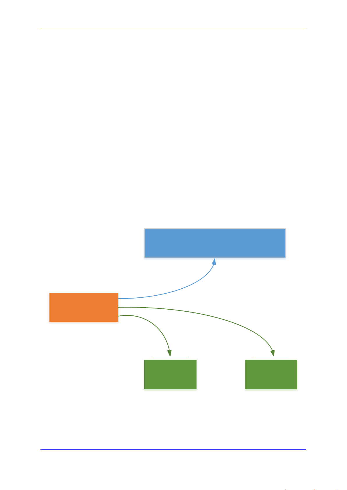
Stack Manager
Stack #1 Stack #2
Virtual Infrastructure Management API
Management & Automation API
2 Deployment
2.1 Operational Environment
Stack Manager is mostly written in Python and may be installed on one of the following
operating systems:
Ubuntu Linux versions 16.04, 18.04, or 20.04
Amazon Linux versions 1 and 2
Red Hat Linux versions 7 and 8
CentOS Linux versions 7 and 8
Debian Linux Version 9
2.2 Network Topology
Stack Manager needs to have access to the following APIs for correct operation:
Virtual Infrastructure Management API (e.g., AWS API) for deploying stack
components and managing their lifecycle.
Management API of the deployed stack (e.g., REST API of Mediant CE) for assessing
operational status of deployed stack instances and managing their configuration and
state.
Figure 2-1: Stack Manager Deployment Topology
Version 7.4 11 Mediant CE
Page 12

Stack Manager
2.3 Installation Prerequisites
2.3.1 Installation Prerequisites for Amazon Web Services (AWS) Environment
Prior to installing Stack Manager in the Amazon Web Services (AWS) environment, make
sure that you meet the following prerequisites:
You have an AWS account. If you don't have one, you can sign up for one on
Amazon's website at http://aws.amazon.com/.
You have created IAM Role that enables Stack Manager to access all needed AW S
APIs. For more information, see Section 2.3.1.1.
Security groups of the "Main Subnet", where Stack Manager will be deployed, allow
Stack Manager to communicate with both the AWS APIs and the deployed Mediant
VE/CE stack instances, using the HTTPS protocol (Port 443).
2.3.1.1 IAM Role for Stack Manager
The following IAM role ensures that Stack Manager can access all needed AWS APIs for
successful stack deployment and management. This role must be attached to the Stack
Manager’s virtual instances, as described in Section 2.4.
{
"Version": "2012-10-17",
"Statement": [
{
"Action": [
"ec2:*",
"cloudformation:*",
"cloudwatch:DeleteAlarms",
"cloudwatch:PutMetricAlarm",
"iam:PassRole",
"iam:ListInstanceProfiles",
"iam:CreateServiceLinkedRole"
],
"Effect": "Allow",
"Resource": "*"
}
]
}
To create an IAM Role
1. Open the AWS IAM console (https://console.aws.amazon.com/iam).
2. Navigate to the Policies screen:
a. Click Create.
b. Select the JSON tab, copy-and-paste the IAM policy rules listed above, and then
click Review policy.
c. Enter the IAM policy name (e.g., "STACK_MGR"), and then click Create policy.
3. Navigate to the Roles screen:
a. Click Create role.
b. Choose EC2 use case, and then click Next: permissions.
User's Manual 12 Document #: LTRT-28931
Page 13

User's Manual 2. Deployment
c. Search for the IAM policy created in the previous step, select it, and then click
Next: tags.
d. Click Next: review.
e. Enter the IAM role name (e.g., "STACK_MGR"), and then click Create role.
The IAM role specified above grants access to all EC2 and CloudFormation APIs. Stack
Manager currently uses the following specific services from these APIs:
"ec2:AllocateAddress",
"ec2:AssociateAddress",
"ec2:AssignPrivateIpAddresses",
"ec2:AttachNetworkInterface",
"ec2:AuthorizeSecurityGroupEgress",
"ec2:AuthorizeSecurityGroupIngress",
"ec2:CreateNetworkInterface",
"ec2:CreatePlacementGroup",
"ec2:CreateSecurityGroup",
"ec2:CreateTags",
"ec2:DeleteNetworkInterface",
"ec2:DeletePlacementGroup",
"ec2:DeleteSecurityGroup",
"ec2:DeleteTags",
"ec2:DescribeAddresses",
"ec2:DescribeImages",
"ec2:DescribeInstances",
"ec2:DescribeInstanceStatus",
"ec2:DescribeKeyPairs",
"ec2:DescribeNetworkInterfaces",
"ec2:DescribePlacementGroups",
"ec2:DescribeRegions",
"ec2:DescribeSecurityGroups",
"ec2:DescribeSubnets",
"ec2:DescribeVpcs",
"ec2:DetachNetworkInterface",
"ec2:DisassociateAddress",
"ec2:ModifyNetworkInterfaceAttribute",
"ec2:ReleaseAddress",
"ec2:RevokeSecurityGroupEgress",
"ec2:RevokeSecurityGroupIngress",
"ec2:RunInstances",
"ec2:StartInstances",
"ec2:StopInstances",
"ec2:TerminateInstances",
"ec2:UnassignPrivateIpAddresses",
"cloudformation:CreateStack",
"cloudformation:DeleteStack",
"cloudformation:DescribeStackEvents",
"cloudformation:DescribeStackResources",
"cloudformation:DescribeStacks",
Version 7.4 13 Mediant CE
Page 14

Stack Manager
"cloudformation:GetTemplate",
"cloudformation:ListStacks",
"cloudformation:UpdateStack"
Note: The above list may change as Stack Manager implementation is updated and new
functionality is added.
2.3.1.2 Subnet and Elastic IP Addresses
Stack Manager uses the following IP addresses when communicating with Mediant VE/CE
stack instances that it deploys:
If the stack instance has a public IP address (Elastic IP) assigned to its management
interface, Stack Manager uses this public IP address to access the stack instance’s
management REST API.
Otherwise, Stack Manager uses the private IP address of the stack instance’s
management interface.
To enable Stack Manager’s access to the deployed Mediant VE/CE stack’s management
APIs, it is recommended to deploy Stack Manager to the same "Main Subnet" that is used
for carrying management traffic of the deployed Mediant VE/CE stack(s).
Stack Manager also needs to communicate with AWS APIs, which are accessible via public
IP addresses. Therefore, it should either be assigned with an Elastic IP address or placed
behind a NAT Gateway.
2.3.2 Installation Prerequisites for Microsoft Azure Environment
Prior to installing Stack Manager in the Microsoft Azure environment, make sure that you
meet the following prerequisites:
You have an Azure account. If you don't have one, you can sign up for one on
Microsoft's website at http://azure.microsoft.com.
Security groups of the "Main Subnet", where Stack Manager will be deployed, allow
Stack Manager to communicate with both the Azure API and the deployed Mediant
VE/CE stack instances, using the HTTPS protocol (Port 443).
2.3.2.1 Subnet and Public IP Addresses
Stack Manager uses the following IP addresses when communicating with Mediant VE/CE
stack instances that it deploys:
If the stack instance has a public IP address assigned to its management interface,
Stack Manager uses this public IP address to access the stack instance’s
management REST API.
Otherwise, Stack Manager uses the private IP address of the stack instance’s
management interface.
To enable Stack Manager’s access to the deployed Mediant VE/CE stack’s management
APIs, it is recommended to deploy Stack Manager to the same "Main Subnet" that is used
for carrying management traffic of the deployed Mediant VE/CE stack(s).
User's Manual 14 Document #: LTRT-28931
Page 15

User's Manual 2. Deployment
Stack Manager also needs to communicate with Azure APIs, which are accessible via public
IP addresses. Therefore, it should either be assigned with a public IP address or placed
behind a NAT Gateway.
2.3.3 Installation Prerequisites for Google Cloud Environment
Prior to installing Stack Manager in the Google Cloud environment, make sure that you meet
the following prerequisites:
You have a Google Cloud account. If you don't have one, you can sign up for one on
Google’s website at http://cloud.google.com.
Firewall Rules of the "Main Subnet", where Stack Manager will be deployed, allow
Stack Manager to communicate with both the Google Cloud API and the deployed
Mediant VE/CE stack instances, using the HTTPS protocol (Port 443).
2.3.3.1 Subnet and External IP Addresses
Stack Manager uses External IP addresses when communicating with Mediant VE/CE stack
instances that it deploys. Therefore, it may be deployed in any subnet as long as it’s assigned
with an External IP and is allowed to communicate with Mediant VE/CE instances.
Nevertheless, to simplify network topology, it is recommended to deploy Stack Manager to
the same "Main Subnet" that is used for carrying management traffic of the deployed Mediant
VE/CE stack(s).
Stack Manager also needs to communicate with Google Cloud APIs, which are accessible
via public IP addresses. Therefore, it should either be assigned with an External IP address
or placed behind a NAT Gateway.
2.3.4 Installation Prerequisites for OpenStack Environment
Prior to installing Stack Manager in the OpenStack environment, make sure that you meet
the following prerequisites:
The OpenStack environment contains the following components:
• Nova
• Neutron
• Cinder
• Glance
• Heat
Security groups of the "Main Subnet", where Stack Manager will be deployed, allow
Stack Manager to communicate with both the OpenStack API and the deployed
Mediant CE stack instances, using the HTTPS protocol (Port 443).
2.3.4.1 Provider Versus Self-Service Networks
Stack Manager supports deployment both in provider (flat) and self-service networks.
Version 7.4 15 Mediant CE
Page 16

Stack Manager
2.3.4.2 Subnet and Floating IP Addresses
Stack Manager uses the following IP addresses when communicating with Mediant VE/CE
stack instances that it deploys:
If the stack instance has a Floating IP address assigned to its management interface,
Stack Manager uses this Floating IP address to access the stack instance’s
management REST API.
Otherwise, Stack Manager uses the private IP address of the stack instance’s
management interface.
To enable Stack Manager’s access to the deployed Mediant VE/CE stack’s management
APIs, it is recommended to deploy Stack Manager to the same "Main Subnet" that is used
for carrying management traffic of the deployed Mediant VE/CE stack(s).
Stack Manager also needs to communicate with OpenStack automation APIs. Make sure
that your network topology enables such communication.
User's Manual 16 Document #: LTRT-28931
Page 17
User's Manual 2. Deployment
2.4 Installation
2.4.1 Overview
For Microsoft Azure, Stack Manager is available in the Azure Marketplace. Therefore, its
deployment consists of a single step, as described in Section 2.4.3, Deploying Stack
Manager on Microsoft Azure.
For other cloud environments, Stack Manager installation consists of two steps:
1. Creating the Instance / Virtual Machine: This step differs, depending on the virtual
environment. For detailed instructions, see the following sections:
• Section 2.4.2, Creating Amazon Web Services (AW S) Instance
• Section 2.4.4, Creating Google Cloud Virtual Machine
• Section 2.4.5, Creating OpenStack Instance
2. Installing the Stack Manager application: For detailed instructions, see Section 2.4.6,
Installing Stack Manager Application
2.4.2 Creating Amazon Web Services (AWS) Instance
The following procedure describes how to create a new AWS instance for running the Stack
Manager application.
To create a new AWS instance for running Stack Manager application:
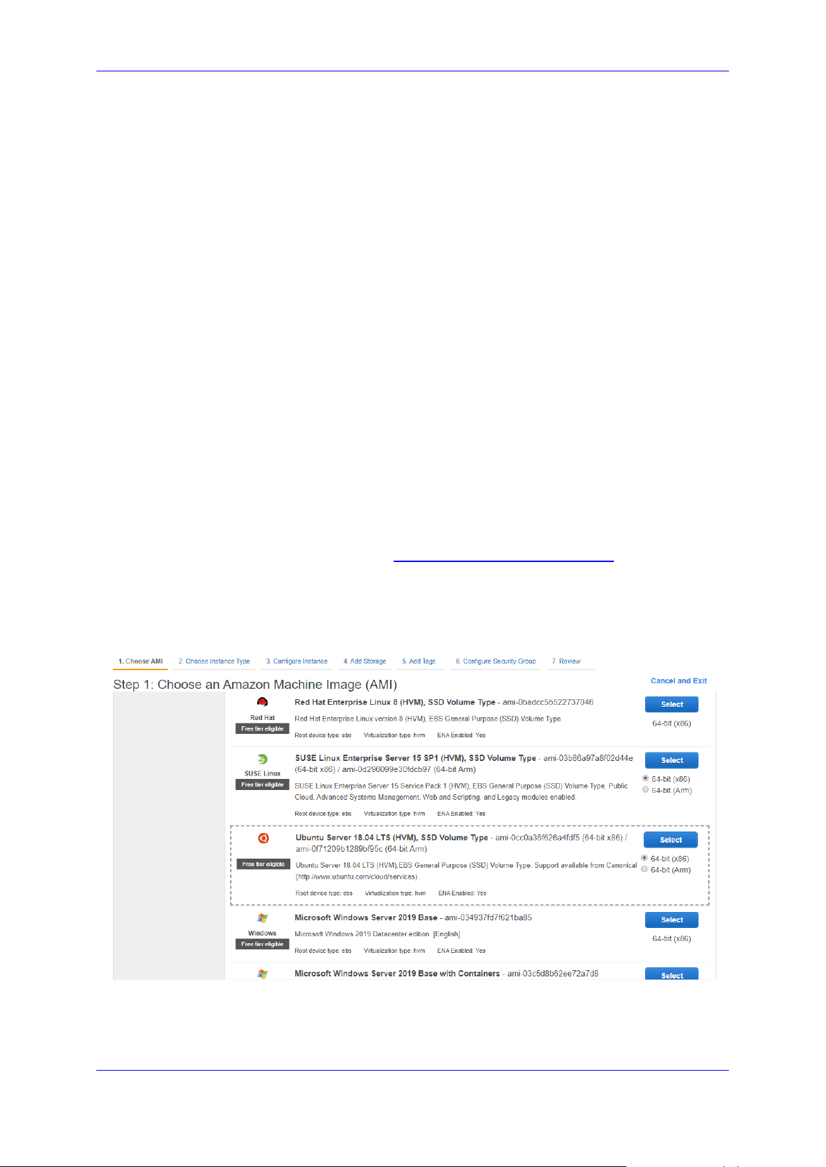
1. Open the AWS EC2 Console at http://console.aws.amazon.com/ec2.
2. In the Instances screen, click Launch Instance.
3. Choose one of the supported operating systems (e.g., "Ubuntu Server 18.04 LTS
(HVM), SSD Volume Type"), and then click Select.
Figure 2-2: Choose an Amazon Machine Image (AMI) – Step 1
Version 7.4 17 Mediant CE
Page 18
Stack Manager
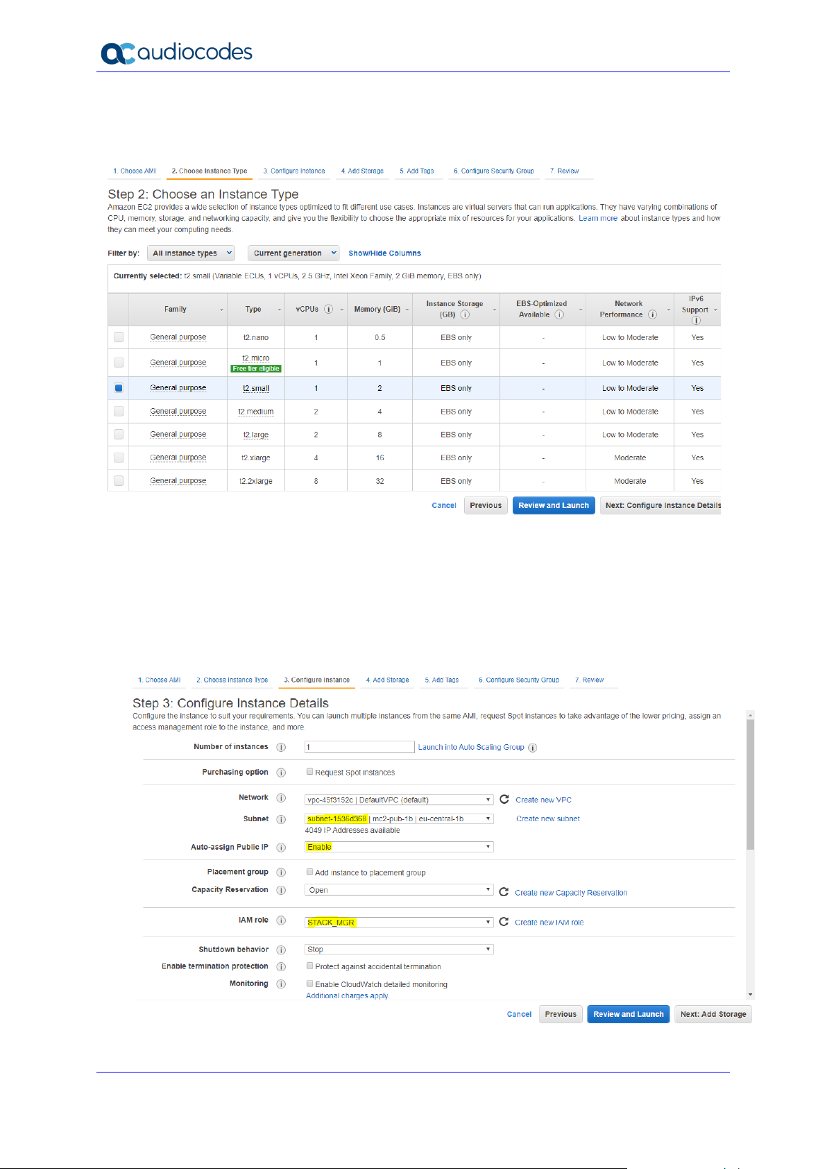
4. In the Choose an Instance Type screen, choose the "t2.small" instance type, and then
click Next; the Configure Instance Details screen appears.
Figure 2-3: Choose an Instance Type – Step 2
5. In the Configure Instance Details screen, configure the following:
• 'Subnet': Choose the "Main Subnet" that is used for connecting to the
management interface of the deployed Mediant VE/CE stack(s).
• 'Auto-assign Public IP': Choose Enable.
• 'IAM Role': Choose the IAM role that you created for Stack Manager in Section
2.3.1.1, IAM Role for Stack Manager.
Figure 2-4: Configure Instance Details – Step 3
User's Manual 18 Document #: LTRT-28931
Page 19
User's Manual 2. Deployment
6. Click Next; the Add Storage screen appears.
7. Click Next; the Add Tags screen appears.
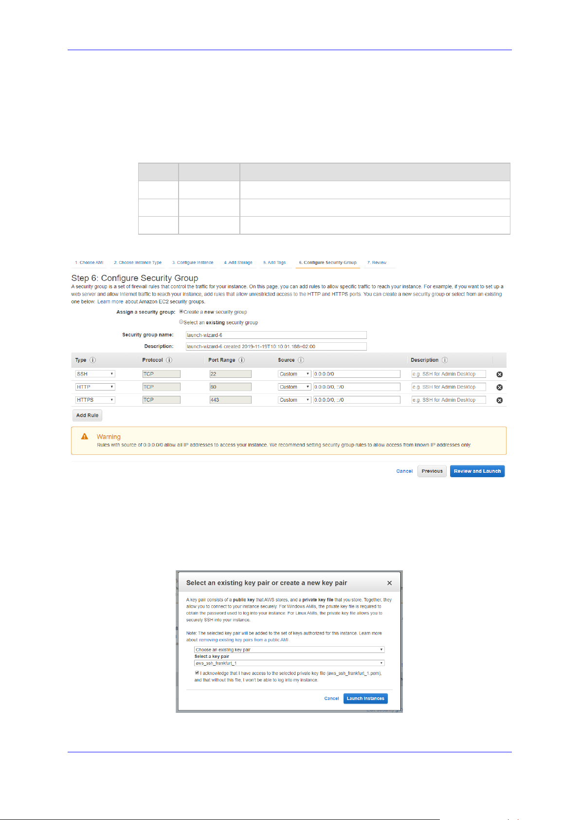
8. Add a Name tag to the instance, and then click Next; the Configure Security Group page
appears.
9. Create a new or choose an existing security group that enables the following ports and
protocols to communicate with the Stack Manager instance:
Port Protocol Purpose
22 TCP SSH connection to Stack Manager’s CLI interface.
80 TCP HTTP connection to Stack Manager’s Web interface.
443 TCP HTTPS connection to Stack Manager’s Web interface.
Figure 2-5: Configure Security Group Step
10. Click Review and Launch; the Review Instance Launch screen appears.
11. Click Launch; the Select an existing key pair … screen appears.
12. Choose an existing key pair or create a new one. Make sure that you have private key
that matches the selected pair because you will need it to connect the deployed instance
through the SSH protocol.
Figure 2-6: Select a Key Pair
13. Click Launch Instances.
Version 7.4 19 Mediant CE
Page 20

Stack Manager
14. Wait until the instance is successfully launched.
15. Connect to the instance through SSH using the default username and configured SSH
key. The default username depends on the image:
Image Default username
Ubuntu 16.04, 18.04 and 20.04 ubuntu
Amazon Linux, Amazon Linux 2, RHEL 7 and 8 ec2-user
CentOS 7 and 8 centos
16. By default, new AWS instances are assigned with a Public IP address that changes
when the instance is stopped or started. If you want Stack Manager’s Public IP address
to remain unchanged, create an Elastic IP and attach it to the instance.
17. Continue with Stack Manager installation, as described in Section 2.4.6, Installing Stack
Manager Application.
User's Manual 20 Document #: LTRT-28931
Page 21
User's Manual 2. Deployment
2.4.3 Deploying Stack Manager on Microsoft Azure
Stack Manager is available in Microsoft Azure Marketplace. Therefore, it is recommended
that you deploy it from there, instead of manually creating a Virtual Machine and installing
Stack Manager application on it.
To deploy Stack Manager on Microsoft Azure:
1. Open the Azure portal at https://portal.azure.com/.
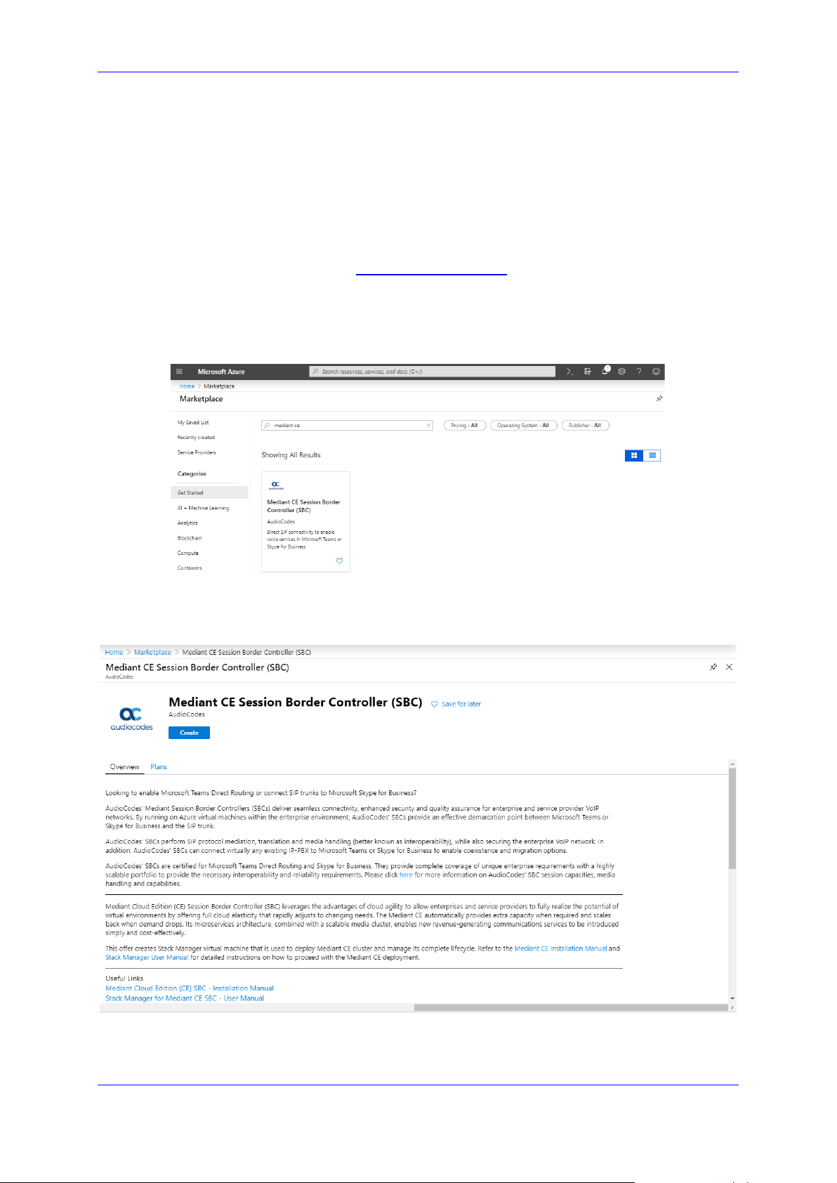
2. Navigate to Azure Marketplace (All services > Marketplace).
3. Search for the product "Mediant CE Session Border Controller (SBC)" published by
AudioCodes.
Figure 2-7: Azure Marketplace
4. Click the "Mediant CE Session Border Controller (SBC)" product; the Mediant CE
Product overview screen appears.
Figure 2-8: Mediant CE SBC Product Offer
5. Click Create; a configuration wizard starts with the Basics page (Step 1).
Version 7.4 21 Mediant CE
Page 22
Stack Manager
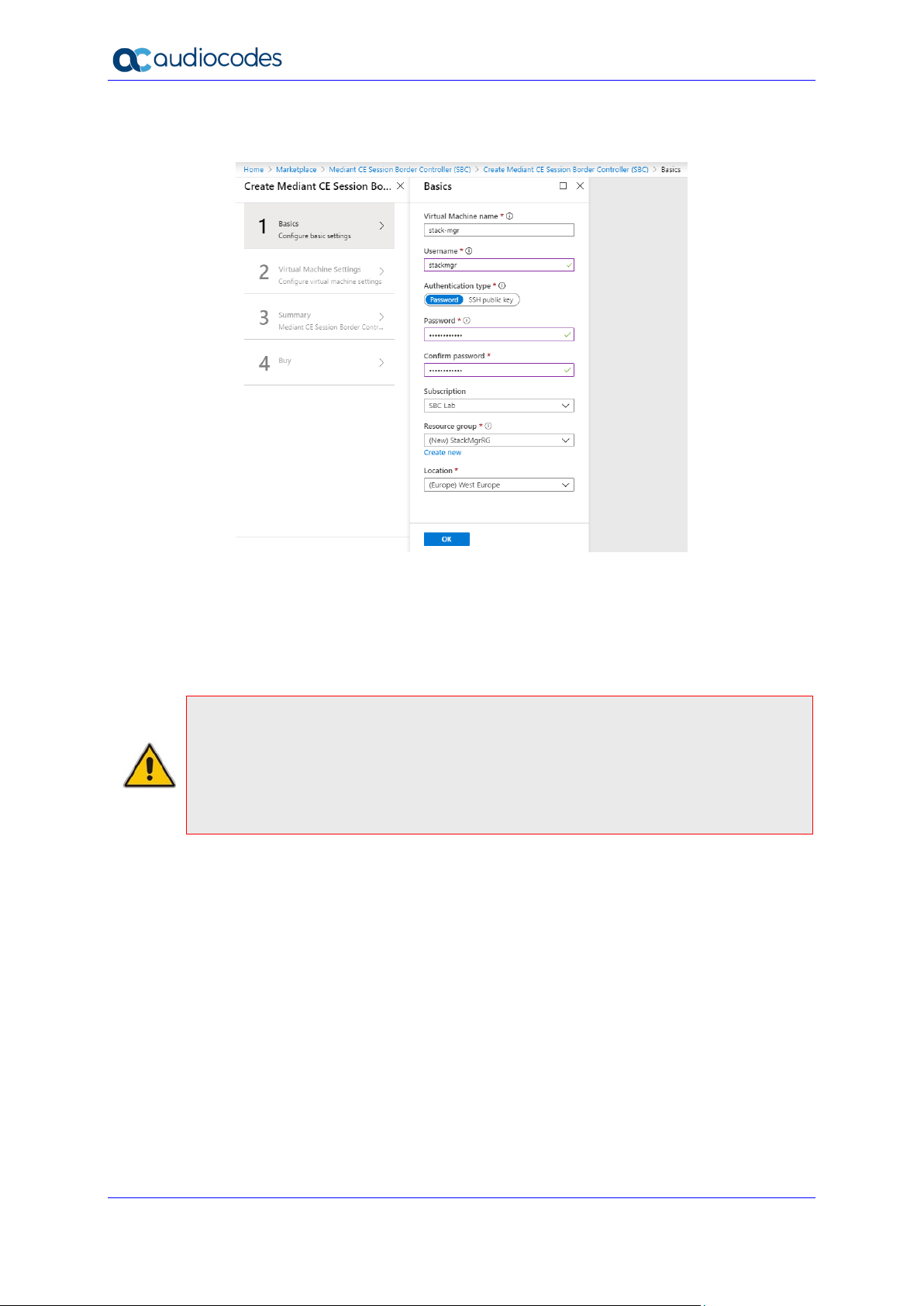
6. In the Basics step, do the following:
Figure 2-9: Basics – Step 1
a. In the 'Virtual Machine name' field, enter a unique name for the new virtual
machine.
b. In the 'Username' field, enter a username.
In the 'Authentication type' field, choose an appropriate authentication type, and
then enter the ‘Password’ or ‘SSH public key’ accordingly. These credentials are
used to connect to the deployed Stack Manager’s CLI interface through SSH.
Note: Azure imposes some limitations on the username and password. For example, it
prohibits the use of "Admin" for the username and requires the use of strong passwords
that meet the following policy:
• A minimum of 12 characters.
• Use of three out of four of the following: lowercase characters, uppercase characters,
numbers, and symbols.
c. From the 'Subscription' drop-down list, select a proper subscription for your
deployment.
d. Under 'Resource group', click Create new, and then enter a new Resource
Group name for your deployment.
e. From the 'Location' drop-down list, select a proper location for your deployment.
f. Click OK; the Virtual Machine Settings page (Step 2) appears.
User's Manual 22 Document #: LTRT-28931
Page 23
User's Manual 2. Deployment
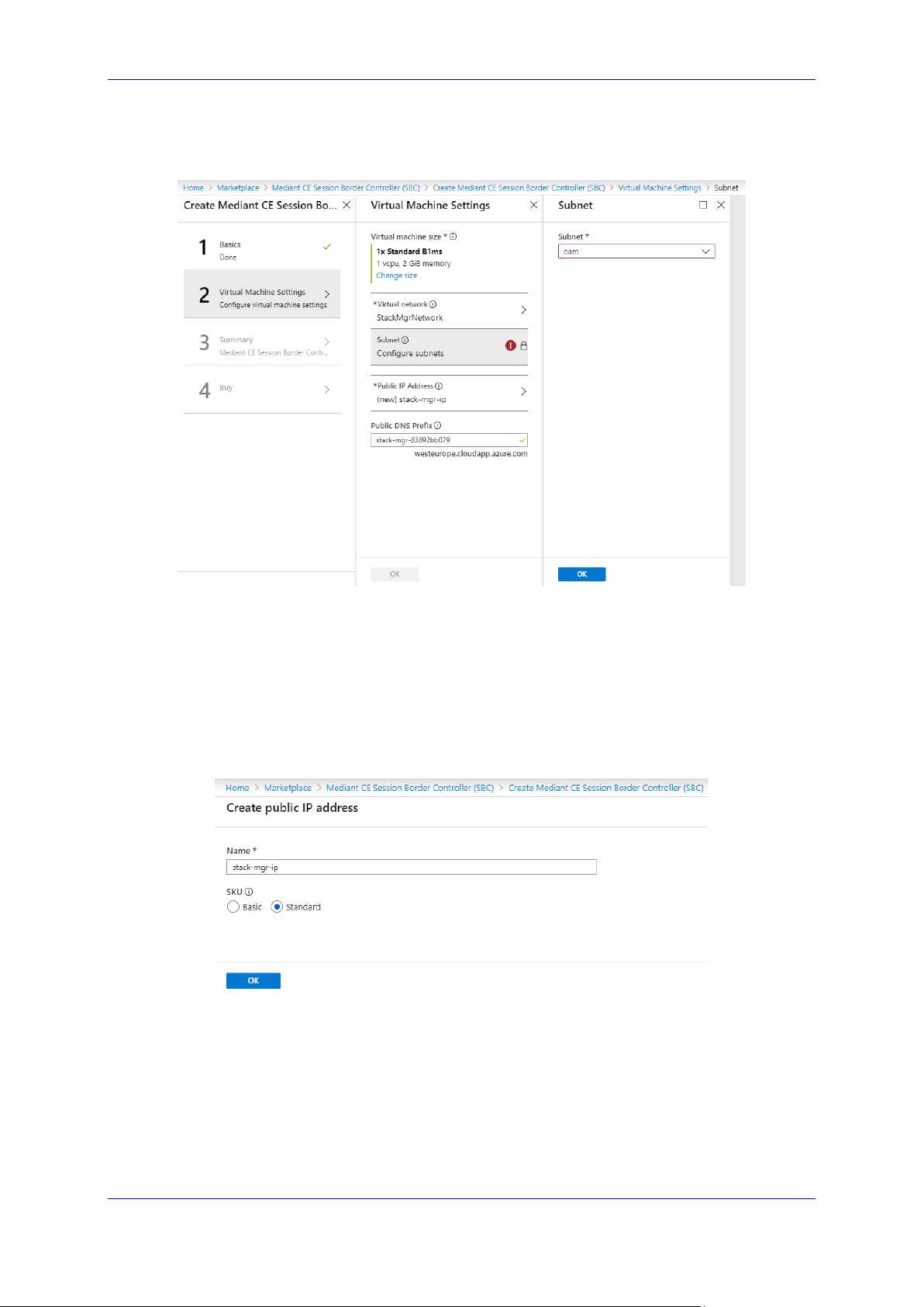
7. In the Virtual Machine Settings step, do the following:
Figure 2-10: Virtual Machine Settings – Step 2
a. Choose the Virtual machine size. Standard_B1ms instance is recommended for
most deployments.
b. Choose the virtual network where Stack Manager will be deployed. Specify the
same network where you intend to deploy the Mediant VE/CE stack(s).
c. Configure the subnet that Stack Manager will be connected to. Specify the same
subnet that will be used for carrying management traffic for the deployed Mediant
VE/CE stack(s).
d. Configure a Public IP address to use Standard SKU:
Figure 2-11: Virtual Machine Settings Step – Creating Public IP Address
e. Click OK.; the Summary page (Step 3) appears.
Version 7.4 23 Mediant CE
Page 24
Stack Manager
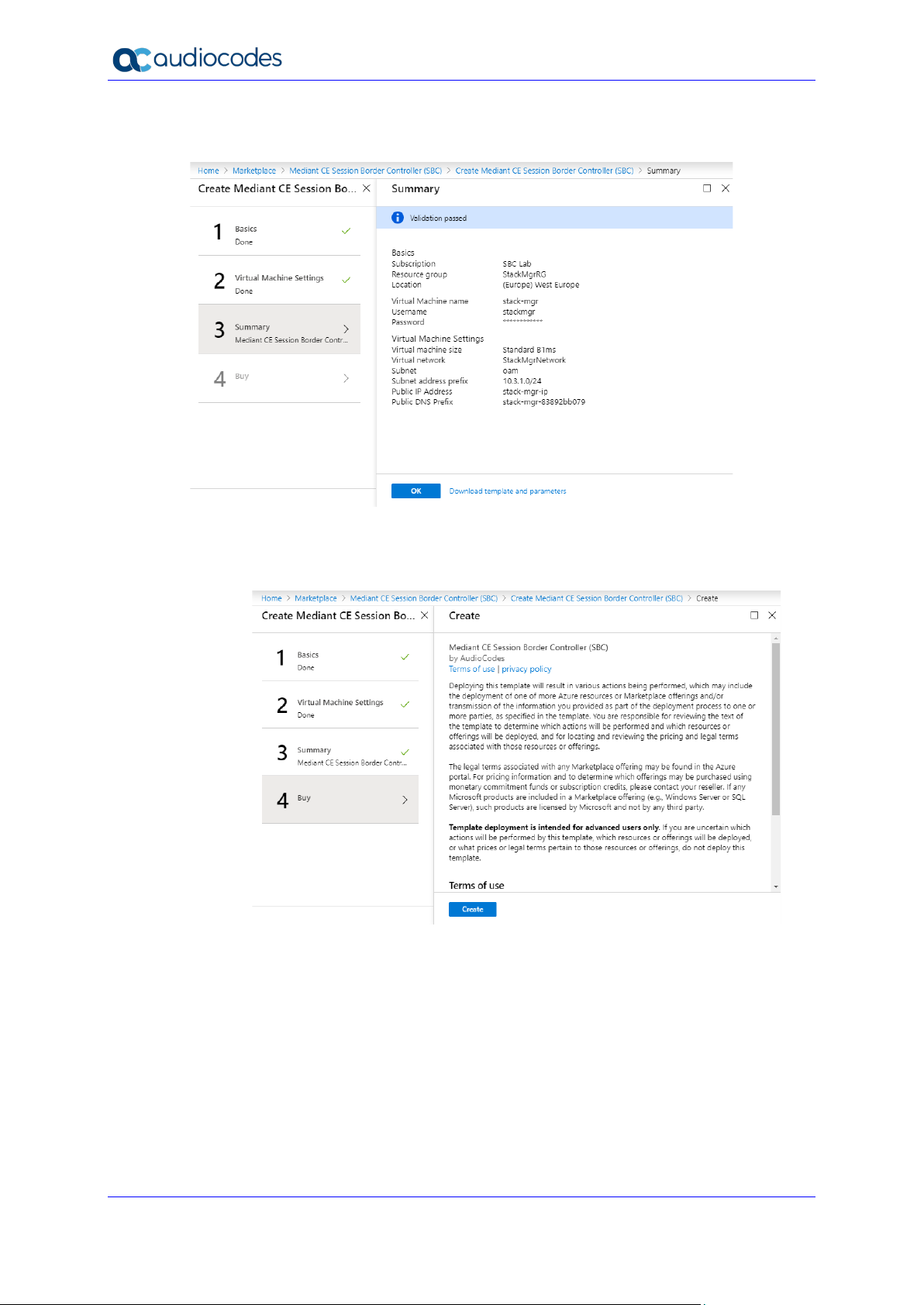
8. In the Summary step, review your virtual machine configuration.
Figure 2-12: Summary – Step 3
9. Click OK; the Buy page (Step 4) appears.
10. Review the Mediant CE SBC terms of use.
11. Click Create to start the virtual machine deployment.
12. Wait until the virtual machine deployment is complete, and then open the Virtual
Machines screen (All services > Virtual Machines).
13. Select the Stack Manager virtual machine.
Figure 2-13: Buy – Step 4
User's Manual 24 Document #: LTRT-28931
Page 25
User's Manual 2. Deployment
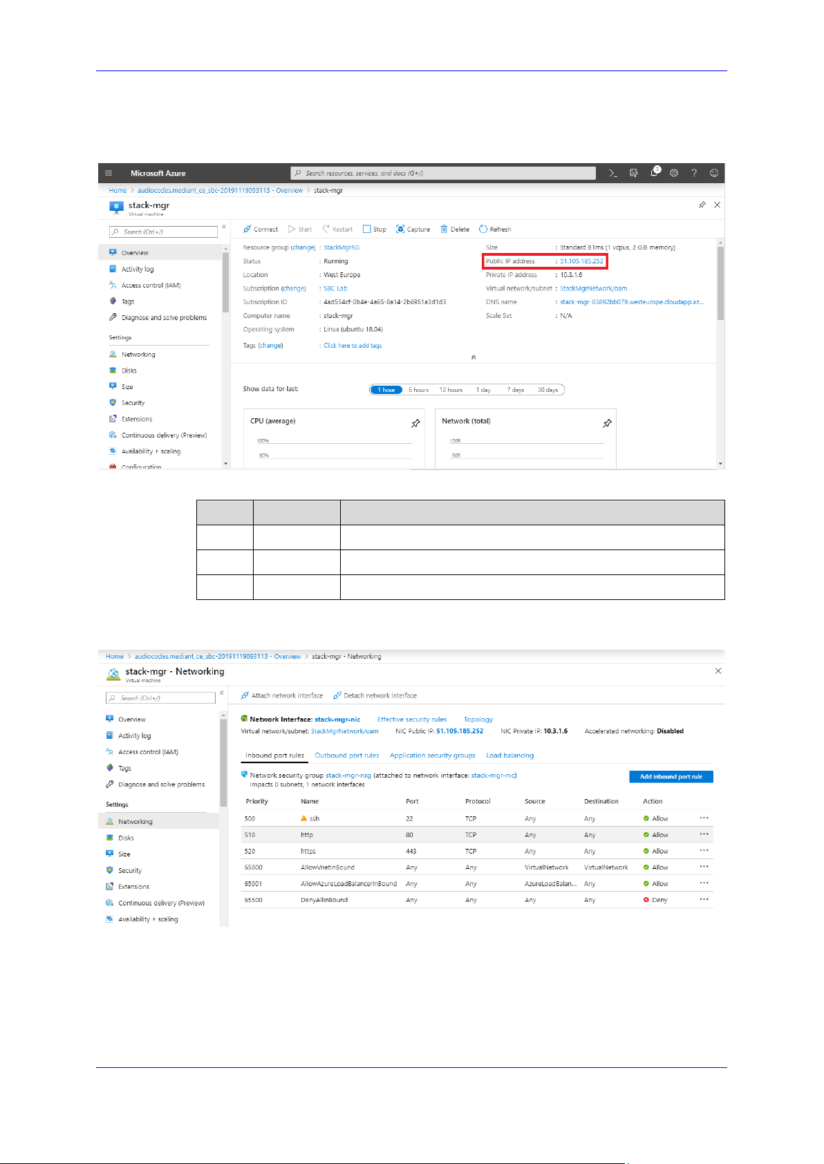
14. In the Overview screen, view the public IP address assigned to it.
Figure 2-14: Determining Public IP Address
15. In the Networking screen, verify that the following ports are open for inbound traffic:
Port Protocol Purpose
22 TCP SSH connection to Stack Manager’s CLI interface.
80 TCP HTTP connection to Stack Manager’s Web interface.
443 TCP HTTPS connection to Stack Manager’s Web interface.
16. If any port is missing, click Add inbound port rule and then add the port.
Figure 2-15: Checking Inbound Port Rules
17. Continue with post-installation configuration, as described in Section 2.8.2, Post-
Installation Configuration on Microsoft Azure.
Version 7.4 25 Mediant CE
Page 26

Stack Manager
2.4.4 Creating Google Cloud Virtual Machine
The following procedure describes how to create a new Google Cloud virtual machine (VM)
for running the Stack Manager application.
To create a new Google Cloud virtual machine for running Stack Manager
application:
1. Open the Google Cloud Console at https://console.cloud.google.com/compute.
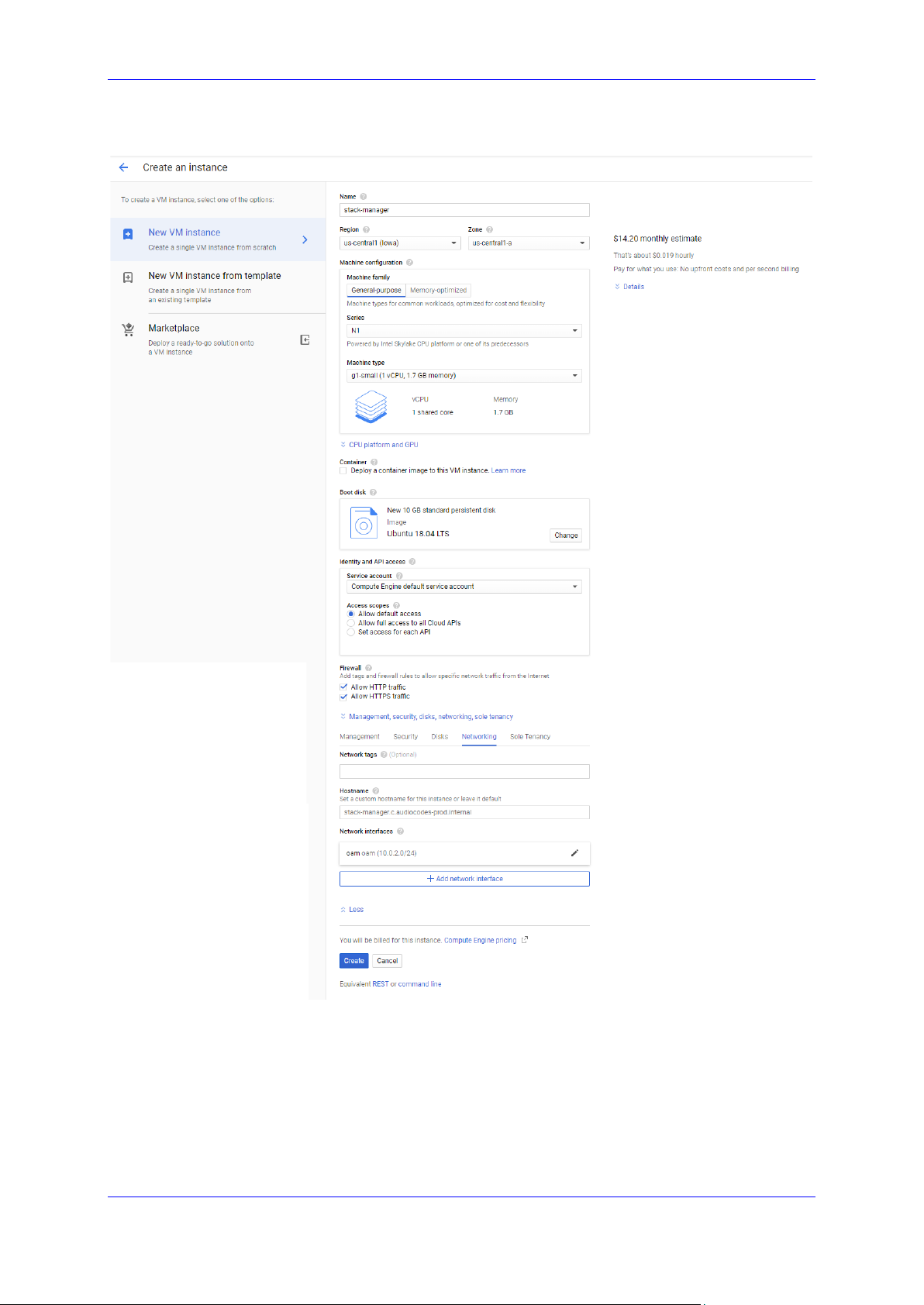
2. On the VM Instances page, click Create Instance.
3. In the 'Name' field, enter a unique name for the new virtual machine.
4. Choose the Region and Zone where Stack Manager will be deployed.
5. Under the ‘Machine Type’ group, choose g1-small (1 shared vCPU, 1.7 GB memory).
6. Under the ‘Boot disk’ group, choose Ubuntu 18.04 LTS or any other supported
operating system.
7. Under the ‘Firewall’ group, select the Allow HTTP traffic and Allow HTTPS traffic
check boxes.
8. Click Management, security, disks, networking, sole tenancy.
9. In the Networking tab for the ‘Network interface’, choose the "Main Network" for
connecting to the management interface of the deployed Mediant VE/CE stack(s).
10. If you want to be able to connect to Stack Manager’s CLI interface through a regular
SSH client (and not through the Google Cloud dashboard), configure the SSH keys
under the Security tab. Note that the username is provided as the last part of the
encoded key. For example, in the following SSH key, "admin" is the username:
ssh-rsa AAAAB3NzaC1yc2EAAAADAQABAA…0Sknr admin
11. Click Create.
User's Manual 26 Document #: LTRT-28931
Page 27
User's Manual 2. Deployment
Figure 2-16: Create Google Cloud Instance
12. By default, new Google Cloud virtual machines are assigned with ephemeral External
IP addresses that change when the instance is stopped or started. If you wish Stack
Manager’s External IP address to remain unchanged, allocate an External IP address
and attach it to the virtual machine.
13. Continue with Stack Manager installation, as described in Section 2.4.6, Installing Stack
Manager Application.
Version 7.4 27 Mediant CE
Page 28
Stack Manager
2.4.5 Creating OpenStack Instance
The following procedure describes how to create a new OpenStack instance for running the
Stack Manager application.
To create an OpenStack instance for running Stack Manager application:
1. Open the OpenStack dashboard.
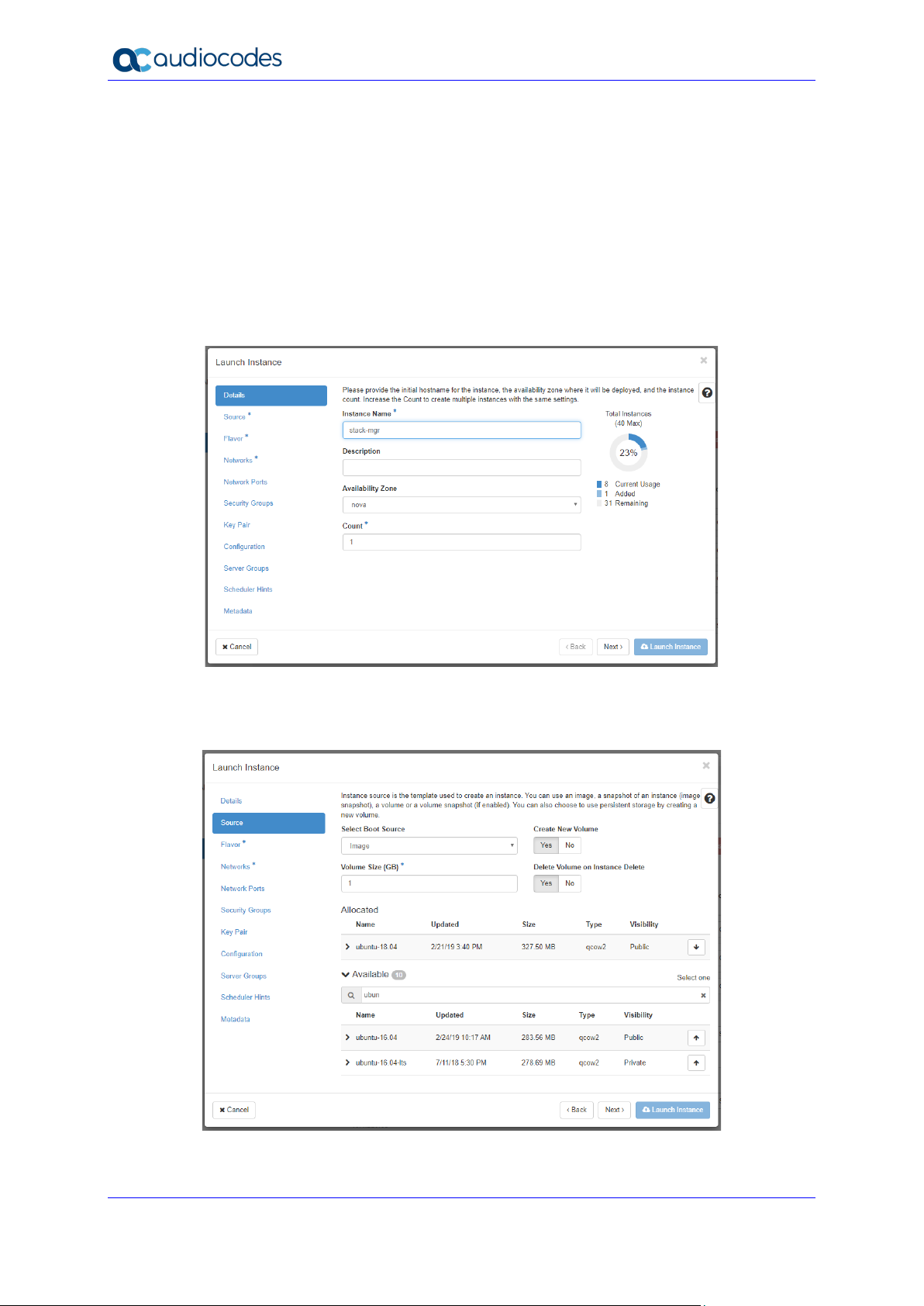
2. On the Instances page, click Launch Instance; the Launch Instance wizard starts with
the Details page.
3. In the 'Instance Name' field, enter a unique name for the new instance.
Figure 2-17: Launch Instance Wizard - Details Page
4. Click Next; the Source wizard page appears.
5. Select one of the supported operating system images (e.g., Ubuntu 18.04).
Figure 2-18: Launch Instance Wizard - Source Page
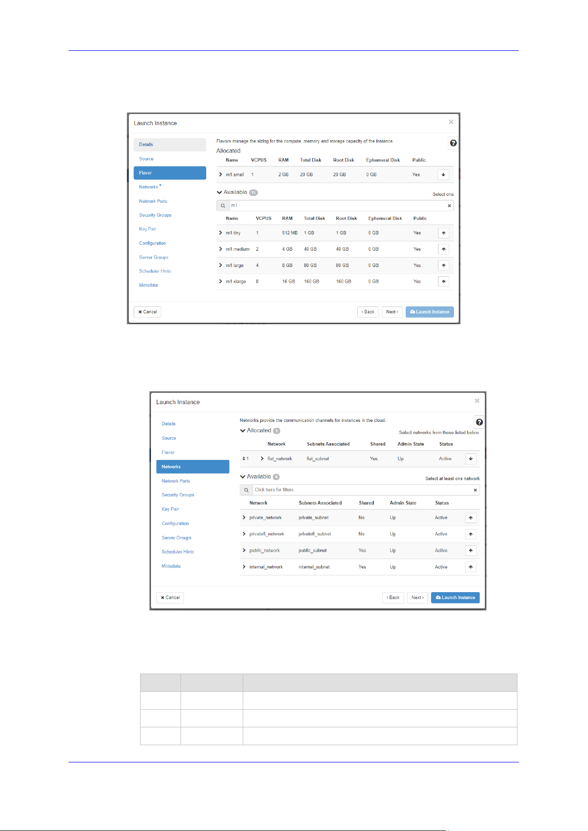
6. Click Next; the Flavor wizard page appears.
User's Manual 28 Document #: LTRT-28931
Page 29
User's Manual 2. Deployment
7. Select the flavor that provides 1 vCPU and 2 GB of RAM.
Figure 2-19: Launch Instance Wizard - Flavor Page
8. Click Next; the Networks wizard page appears.
9. Select the "Main Network" that will be used for connecting to the management interface
of the deployed Mediant VE/CE stack(s).
Figure 2-20: Launch Instance Wizard - Networks Page
10. Click Next; the Network Ports wizard page appears.
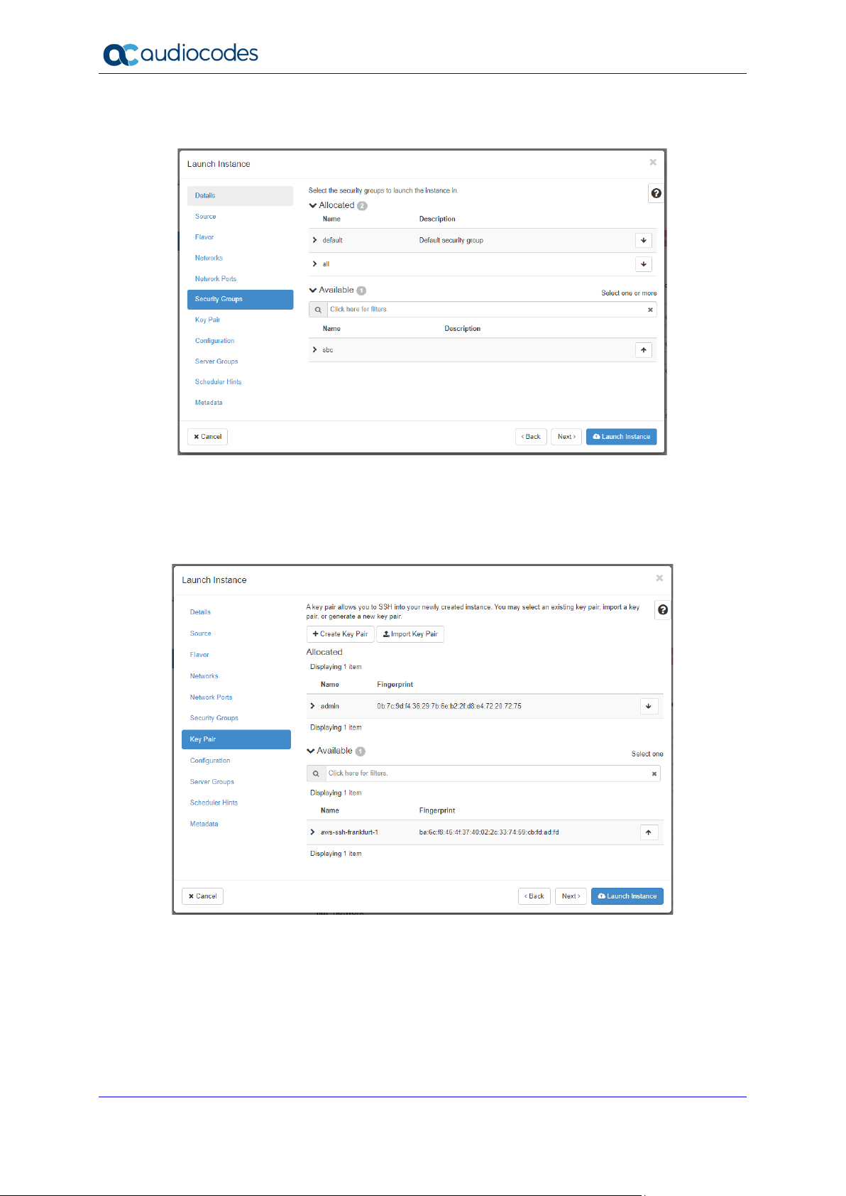
11. Click Next; the Security Groups wizard page appears.
12. Select a security group that enables the following ports and protocols to communicate
with the Stack Manager instance:
Port Protocol Purpose
22 TCP SSH connection to Stack Manager’s CLI interface.
80 TCP HTTP connection to Stack Manager’s Web interface.
443 TCP HTTPS connection to Stack Manager’s Web interface.
Version 7.4 29 Mediant CE
Page 30
Stack Manager
Figure 2-21: Launch Instance Wizard - Security Groups Page
13. Click Next; the Key Pair wizard page appears.
Select an existing key pair or create a new one. Make sure that you have private key
that matches the selected pair because you will need it to connect the deployed instance
through SSH.
Figure 2-22: Launch Instance Wizard - Key Pair Page
14. Click Launch Instance.
15. Continue with Stack Manager installation, as described in Section 2.4.6, Installing Stack
Manager Application.
User's Manual 30 Document #: LTRT-28931
Page 31

User's Manual 2. Deployment
Stack Manager from Azure
sudo apt
2.4.6 Installing Stack Manager Application
The following procedure describes how to install the Stack Manager application after
successfully creating the instance / virtual machine.
Note: This step is not needed if you are deploying
Marketplace.
To install Stack Manager application:
1. Log in to the launched virtual instance / machine through SSH, using the credentials
obtained during the launch.
2. Run the following command to download the latest installation package:
$ curl http://redirect.audiocodes.com/install/stack_mgr/stack_
mgr.zip --output stack_mgr.zip
Alternatively, you may download the installation package manually from
http://redirect.audiocodes.com/install/index.html and then transfer it to the virtual
instance / machine through an SCP/SFTP client (e.g., WinSCP).
3. Run the following commands to start the installation:
$ unzip stack_mgr.zip
$ sudo bash stack_mgr/install.sh
Note: If the unzip command above fails due to the lack of “unzip” package, install it using
distribution-specific package manager. For example, for Ubuntu Linux, type
install unzip.
4. Continue with post-installation configuration, as described in Section 2.8, Post-
installation Configuration.
Version 7.4 31 Mediant CE
Page 32

Stack Manager
2.5 Accessing the Web Interface
Stack Manager’s Web interface is accessed by connecting to the virtual machine through
HTTP/HTTPS, using one of the supported web browsers:
Google Chrome
Firefox
Microsoft Edge
Figure 2-23: Web Interface of Stack Manager
The default login credentials of the Web Interface are:
Username: Admin
Password: Admin
It is recommended to change the login credentials on first login.
User's Manual 32 Document #: LTRT-28931
Page 33

User's Manual 2. Deployment
To change default Web credentials:
1. Log in to the Web interface.
2. Open the Configuration page.
3. In the 'Admin Username' field, enter the new username.
4. In the 'Admin Password' field, enter the new password.
Figure 2-24: Changing Web Login Credentials
5. Click Update.
2.6 Accessing the CLI
Stack Manager’s CLI interface is accessed by switching to the stack_mgr user, using the
following command:
$ stack_mgr_cli
If the above command doesn’t function, close the current SSH session and then open a new
one. If the problem persists, use the following alternative syntax:
$ sudo su - stack_mgr
Version 7.4 33 Mediant CE
Page 34

Stack Manager
2.7 Upgrading Stack Manager
To upgrade the Stack Manager application to the latest version, log in to the virtual instance
(machine) through SSH as a regular user (e.g., ubuntu), and then run the following
command:
$ sudo /opt/stack_mgr/update.sh
The command 1) checks if a new Stack Manager application version was published on
AudioCodes website, 2) if yes, downloads it, and then 3) updates the current installation. All
configuration and created stacks are preserved. The upgrade operation has no effect on
Mediant VE/CE stacks service.
The update.sh script supports the following optional parameters:
--force: Performs an upgrade even if the current Stack Manager version is later or
equal to the one published on AudioCodes website. (This may be useful if the upgrade
operation failed and needs to be re-run.)
--test: Checks if a new version is available, but doesn't perform an upgrade.
--verify: Similar to --test, but also outputs the change log for the new version.
Alternatively, you can upgrade Stack Manager by installing a new version using the regular
installation procedure (see Section 2.4.6, Installing Stack Manager Application for details).
All existing configuration and stacks are preserved.
Note: When upgrading Stack Manager through the regular installation procedure, make
sure that you log in as a regular user (e.g., "ubuntu") and that you do not enter Stack
Manager's CLI (via the "stack_mgr_cli" command).
User's Manual 34 Document #: LTRT-28931
Page 35

User's Manual 2. Deployment
2.8 Post-installation Configuration
The following procedures describe post-installation configuration that ensures that Stack
Manager is able to properly access cloud / virtual infrastructure APIs.
The instructions depend on the cloud / virtual environment.
After performing the configuration, verify that Stack Manager is able to operate normally, as
described in Section 2.8.5, Verifying Configuration.
For production environments, it is also recommended to configure Stack Manager to store
its run-time data on cloud storage services, as described in Section 2.9, Runtime Data.
Note: The instructions described in this section use the Web interface to configure Stack
Manager. The same tasks may be performed through CLI, using the configure
command, as described in Section Global Configuration.
2.8.1 Post-installation Configuration on Amazon Web Services (AWS)
The following procedure describes post-installation configuration of the Stack Manager
application in the Amazon Web Services (AWS) environment, which consists of the following
step:
Enabling Stack Manager virtual machine access to AWS APIs
2.8.1.1 Enabling Access to AWS API via IAM Role (Recommended Method)
Before using Stack Manager, you need to ensure that it has access to the AWS API. The
recommended method for achieving this is to create an IAM role, as described in Section
2.3.1.1, IAM Role for Stack Manager, and then to attach it to the Stack Manager’s virtual
instance during its creation, as described in Section 2.4.2, Creating Amazon Web Services
(AWS) Instance.
2.8.1.2 Enabling Access to AWS API via AWS Access Key (Alternative Method)
This section describes an alternative method for enabling Stack Manager access to AWS
APIs. For typical deployments, please use the recommended method instead, as described
in Section 2.8.1.1, Enabling Access to AWS API via IAM Role (Recommended Method).
To configure Stack Manager access to AWS API using access key:
1. Obtain the AWS access key with permissions listed in Section 2.3.1.1, IAM Role for
Stack Manager. For more information on how to do this, refer to AWS documentation at
https://docs.aws.amazon.com/general/latest/gr/aws-sec-cred-types.html#access-keysand-secret-access-keys.
2. Log in to the Stack Manager Web interface.
3. Open the Configuration page.
4. Enter the access key values in the 'AWS Access Key' and 'AWS Secret Key' fields.
5. Click Update.
Version 7.4 35 Mediant CE
Page 36

Stack Manager
2.8.2 Post-Installation Configuration on Microsoft Azure
The following procedure describes post-installation configuration of the Stack Manager
application in Microsoft Azure environment, which includes the following steps:
1. Configuring the Azure Subscription ID.
2. Enabling Stack Manager virtual machine access to Azure APIs.
2.8.2.1 Configuring the Azure Subscription ID
After installing Stack Manager, you need to configure the Subscription ID where it will
operate.
To configure Azure Subscription ID:
1. Open the Azure portal at https://portal.azure.com/.
2. Navigate to Subscriptions (All services > Subscriptions).
3. Locate your Azure Subscription ID.
Figure 2-25: Locating Subscription ID
4. Log in to the Stack Manager Web interface.
5. Open the Configuration page.
6. Enter the Azure subscription ID in the 'Azure Subscription ID' field.
User's Manual 36 Document #: LTRT-28931
Page 37

User's Manual 2. Deployment
Figure 2-26: Configuring Azure Subscription ID
7. Click Update.
2.8.2.2 Enabling Access to Azure APIs via Managed Service Identity (Recommended Method)
Before using Stack Manager, you need to ensure that it has access to Azure APIs. This
section describes the recommended method for achieving this through the Managed Service
Identity. The method consist of two steps:
1. Enabling Managed Service Identity for the Stack Manager virtual machine.
2. Assigning a proper IAM role to the Stack Manager virtual machine.
An alternative method is to use the service principal, as described in Section 2.8.2.3,
Enabling Access to Azure APIs via Service Principal (Alternative Method).
Managed Service Identity (MSI) enables the assignment of access control (IAM) roles to a
specific Azure virtual machine deployed in Azure.
To enable Managed Service Identity:
1. Open the Azure portal at http://portal.azure.com.
1. Navigate to the Virtual Machines page.
2. Select the Stack Manager virtual machine.
Version 7.4 37 Mediant CE
Page 38

Stack Manager
3. In the Navigation menu, click Identity, and then enable Managed Service Identity.
Figure 2-27: Configuring Virtual Machine’s Managed Service Identity
Once you have performed the above procedure, you should grant the Stack Manager virtual
machine permissions to access all needed Azure APIs for successful stack deployment and
management. There are several ways to achieve this:
Option 1 (recommended): Assign Stack Manager with the "Contributor" role at the
Subscription level.
Option 2: Assign Stack Manager with custom IAM roles at Subscription, Network and
Resource Group levels.
2.8.2.2.1 Option 1: "Contributor" Role at Subscription Level
This method provides Stack Manager with complete access to Subscription resources,
including the ability to create new Resource Groups. This method is recommended for most
users, as it's simple to provision and doesn’t impose any restrictions on Stack Manager
functionality.
To assign Stack Manager with "Contributor" role at Subscription level:
1. Open the Azure portal at http://portal.azure.com.
2. Navigate to the Subscriptions page.
3. Select your subscription.
4. In the Navigation menu, click Access Control (IAM), and then click Add a role
assignment:
a. From the 'Role' drop-down list, select Contributor.
b. From the 'Assign access to' drop-down list, select Virtual Machine.
User's Manual 38 Document #: LTRT-28931
Page 39

User's Manual 2. Deployment
c. From the 'Select' drop-down list, select the name of Stack Manager’s virtual
machine.
d. Click Save.
Figure 2-28: Adding Role Assignment
2.8.2.2.2 Option 2: Custom IAM Roles at Subscription, Network and Resource Group Levels
This method limits Stack Manager administrative access to the specific pre-defined
Resource Group(s). It is more complicated to provision and slightly complicates stack
creation. Therefore, this method is recommended for advanced users who want to minimize
IAM permissions granted to the Stack Manager.
With this method, Stack Manager is assigned the following IAM roles:
Scope IAM Role
Subscription Custom IAM role that includes read-only access for specific resources
only (e.g., virtual networks and subnets). This is needed for displaying
"Create new stack" Web UI dialog and validating stack configuration
during create, modify, update, and heal operations.
Virtual Network Custom IAM role that grants Stack Manager the ability to deploy new
virtual machines into the specific Virtual Network(s).
The role is assigned only for specific Virtual Networks where new
stacks will be deployed.
Resource Group
Custom IAM role that grants Stack Manager the ability to create,
modify and delete stack resources (e.g., virtual machines, network
interfaces, load balancers).
The role is assigned only for specific Resource Group(s) that must be
pre-created prior to stack deployment.
Note: When using this method, an empty Resource Group must be manually created
prior to stack deployment. The name of this Resource Group must be specified during
new stack creation through the Advanced Config parameter resource_group.
Version 7.4 39 Mediant CE
Page 40

Stack Manager
To assign Stack Manager with custom IAM roles at Subscription, Network and
Resource Group levels:
1. Create the following three custom IAM roles:
• Custom IAM Role 'Stack Manager Subscription Role':
{
"properties": {
"roleName": "Stack Manager Subscription Role",
"description": "Subscription role for AudioCodes Stack Manager.",
"assignableScopes": [
"/subscriptions/{subscriptionId}"
],
"permissions": [
{
"actions": [
"Microsoft.Network/virtualNetworks/read",
"Microsoft.Network/virtualNetworks/subnets/read",
"Microsoft.Network/publicIPAddresses/read",
"Microsoft.Compute/images/read",
"Microsoft.Compute/skus/read",
"Microsoft.Compute/virtualMachines/vmSizes/read",
"Microsoft.MarketplaceOrdering/offertypes/publishers/
offers/plans/agreements/read",
"Microsoft.MarketplaceOrdering/offertypes/publishers/
offers/plans/agreements/write"
],
"notActions": [],
"dataActions": [],
"notDataActions": []
}
]
}
}
• Custom IAM Role 'Stack Manager Network Role':
{
"properties": {
"roleName": "Stack Manager Network Role",
"description": "Network role for AudioCodes Stack Manager.",
"assignableScopes": [
"/subscriptions/{subscriptionId}"
],
"permissions": [
{
User's Manual 40 Document #: LTRT-28931
Page 41

User's Manual 2. Deployment
"actions": [
"Microsoft.Network/virtualNetworks/subnets/join/action"
],
"notActions": [],
"dataActions": [],
"notDataActions": []
}
]
}
}
• Custom IAM Role 'Stack Manager Resource Group Role':
{
"properties": {
"roleName": "Stack Manager Resource Group Role",
"description": "",
"assignableScopes": [
"/subscriptions/{subscriptionId}/resourcegroups/{rgName}"
],
"permissions": [
{
"actions": [
"Microsoft.Compute/availabilitySets/*",
"Microsoft.Compute/proximityPlacementGroups/*",
"Microsoft.Compute/locations/*",
"Microsoft.Compute/virtualMachines/*",
"Microsoft.Compute/disks/write",
"Microsoft.Compute/disks/read",
"Microsoft.Compute/disks/delete",
"Microsoft.Network/networkInterfaces/*",
"Microsoft.Network/networkSecurityGroups/*",
"Microsoft.Network/publicIPAddresses/* ",
"Microsoft.Resources/deployments/*",
"Microsoft.Storage/storageAccounts/*",
"Microsoft.Network/loadBalancers/*",
"Microsoft.Network/loadBalancers/backendAddressPools/*",
"Microsoft.Network/loadBalancers/probes/*",
"Microsoft.Network/loadBalancers/outboundRules/*",
"Microsoft.Network/loadBalancers/loadBalancingRules/*",
"Microsoft.Network/loadBalancers/frontendIPConfigurations/*",
"Microsoft.Resources/subscriptions/resourceGroups/read"
],
Version 7.4 41 Mediant CE
Page 42

Stack Manager
"notActions": [],
"dataActions": [],
"notDataActions": []
}
]
}
}
Refer to Azure documentation at https://docs.microsoft.com/en-us/azure/role-based-
access-control/custom-roles for detailed instructions on how to create custom IAM
roles.
2. Open the Azure portal at http://portal.azure.com.
3. Navigate to the Subscriptions page.
4. Select your subscription.
5. In the Navigation menu, click Access Control (IAM), and then click Add a role
assignment:
a. From the 'Role' drop-down list, select Stack Manager Subscription Role.
b. From the 'Assign access to' drop-down list, select Virtual Machine.
c. From the 'Select' drop-down list, select the name of Stack Manager’s virtual
machine.
d. Click Save.
6. Navigate to the Virtual Networks page.
7. Select the network where new stacks will be deployed.
8. In the Navigation menu, click Access Control (IAM), and then click Add a role
assignment:
a. From the 'Role' drop-down list, select Stack Manager Network Role.
b. From the 'Assign access to' drop-down list, select Virtual Machine.
c. From the 'Select' drop-down list, select the name of Stack Manager’s virtual
machine.
d. Click Save.
9. Navigate to the Resource Groups page.
10. Click Add to create a new Resource Group(s) where new stacks will be deployed. Each
stack will require a dedicated Resource Group that must be empty prior to stack
creation.
a. Enter the Resource Group name.
b. From the 'Region' drop-down list, select the region where the new stack will be
deployed.
c. Click Create.
11. Select the created Resource Group(s).
12. In the Navigation menu, click Access Control (IAM), and then click Add a role
assignment:
a. From the 'Role' drop-down list, select Stack Manager Resource Group Role.
b. From the 'Assign access to' drop-down list, select Virtual Machine.
c. From the 'Select' drop-down list, select the name of Stack Manager’s virtual
machine.
d. Click Save.
13. Restart the Stack Manager virtual machine to apply the new IAM credentials.
User's Manual 42 Document #: LTRT-28931
Page 43

User's Manual 2. Deployment
2.8.2.2.2.1 Advanced Restriction of Custom IAM Roles
Custom IAM roles, described in the previous section, may further be restricted if you choose
to pre-create some Azure resources (e.g., public IP addresses) and/or are willing to deploy
the new stack via the CLI interface.
The following permissions may be dropped from the Stack Manager Subscription Role:
Permission What happens when it is dropped
Microsoft.Network/
virtualNetworks/read
Microsoft.Network/
virtualNetworks/subnets/read
Microsoft.Network/
publicIPAddresses/read
You will be unable to create the new stack through the Web
interface. Use the CLI or REST interface to create the new
stack. After initial creation, further stack management may
be performed through all management interfaces, including
Web interface.
Stack Manager will not be able to validate the Virtual
Network name prior to stack deployment. If the wrong
name is provided, stack deployment will fail.
You will be unable to create the new stack through the Web
interface. Use the CLI or REST interfaces to create the new
stack. After initial creation, further stack management may
be performed through all management interfaces, including
Web interface.
Stack Manager will not be able to validate Subnet names
prior to stack deployment. If wrong names are provided,
stack deployment will fail.
You must specify the CIDR for each subnet through the
Advanced Config parameters: cluster_subnet_cidr,
main_subnet_cidr, additional1_subnet_cidr,
additional2_subnet_cidr. Otherwise, Stack Manager will
not be able to properly configure network interfaces for
deployed stack components.
Stack Manager will not be able to validate predefined
Public IP addresses provided via public_ip_* Advanced
Config parameters. If wrong names are provided, stack
deployment will fail.
Microsoft.Compute/
images/read
Microsoft.Compute/
skus/read
Microsoft.MarketplaceOrdering/
offertypes/publishers/offers/
plans/agreements/read
Microsoft.MarketplaceOrdering/
offertypes/publishers/offers/
plans/agreements/write
Version 7.4 43 Mediant CE
Stack Manager will not be able to validate custom VM
images provided via sc_image_id / mc_image_id
Advanced Config parameters. If wrong names are
provided, stack deployment will fail.
Stack Manager will not be able to validate instance types
(VM sizes) provided via sc_instance_type /
mc_instance_type Advanced Config parameters. If wrong
names are provided, stack deployment will fail.
Stack Manager will not be able to automatically accept
publisher agreement for Mediant VE/CE Marketplace offer.
You need to manually accept the agreement prior to new
stack deployment through the following CLI command:
az vm image terms accept \
--publisher audiocodes \
--offer mediantsessionbordercontroller \
--sku mediantvesbcazure
Page 44

Stack Manager
If you are deploying SBC version based on CentOS 6, use -
Permission What happens when it is dropped
-sku mediantvirtualsbcazure in the above command.
If agreement is not accepted stack deployment will fail.
The following permissions may be dropped from the Stack Manager Resource Group Role:
Permission What happens when it is dropped
Microsoft.Network/
networkSecurityGroups/*
Microsoft.Network/
publicIPAddresses/*
Microsoft.Storage/
storageAccounts/*
You must precreate network security groups and provide them via
cluster_nsg_id / oam_nsg_id / signaling_nsg_id /
media_nsg_id Advanced Config parameters during the new
stack creation.
Stack Manager VM must be granted with
Microsoft.Network/networkSecurityGroups/actions/join
permission in the Resource Group where network security groups
reside.
You must precreate public IP addresses and provide them via
public_ip_* Advanced Config parameters during the new stack
creation.
Stack Manager VM must be granted with
Microsoft.Network/publicIPAddresses/read and
Microsoft.Network/publicIPAddresses/actions/join
permissions in the Resource Group where public IP addresses
reside.
You must precreate diagnostics Storage Account and provide it
via diag_account Advanced Config parameters during the new
stack creation.
Stack Manager VM must be granted with
Microsoft.Storage/storageAccounts/read permission in the
Resource Group where Storage Account resides.
2.8.2.3 Enabling Access to Azure APIs via Service Principal (Alternative Method)
This section describes an alternative method for enabling Stack Manager access to Azure
APIs. For typical deployments, please use the recommended method instead, as described
in Section 2.8.2.2, Enabling Access to Azure APIs via Managed Service Identity
(Recommended Method).
To configure Stack Manager access to Azure API using Service Principal:
1. Create an Azure Service Principal, as described in the Azure documentation at
https://docs.microsoft.com/en-us/azure/active-directory/develop/app-objects-andservice-principals. Assign an appropriate IAM role(s) to the created Azure Service
Principal, as described in the previous section.
2. Log in to the Stack Manager Web interface.
3. Open the Configuration page.
4. Enter the values in the 'Azure Tenant ID', 'Azure Client ID' and 'Azure Secret' fields.
5. Click Update.
User's Manual 44 Document #: LTRT-28931
Page 45

User's Manual 2. Deployment
2.8.3 Post-Installation Configuration on Google Cloud
The following procedure describes post-installation configuration of the Stack Manager
application in Google Cloud environment, which includes the following steps:
1. Configuring Google Project ID.
2. Enabling Google Cloud APIs in the Project.
3. Enabling Stack Manager virtual machine access to Google Cloud APIs.
2.8.3.1 Configuring Google Project ID
After installing Stack Manager, you need to configure the Project ID where it will operate.
To configure Google Project ID:
1. In Google Cloud Platform Console, go to the Home > Dashboard
(https://console.cloud.google.com/home/dashboard), and then determine your project
ID.
Figure 2-29: Determining Google Project ID
2. Log in to the Stack Manager Web interface.
3. Open the Configuration page.
4. In the 'Google Project' field, enter the Project ID.
5. Click Update.
2.8.3.2 Enabling APIs in Project
The following Google Cloud APIs must be enabled in the Project for normal Stack Manager
operation:
Compute Engine API
Cloud Deployment Manager V2 API
Cloud Resource Manager API
To enable APIs in the project:
1. In the Google Cloud Platform Console, go to the API & Services > Dashboard page
(https://console.cloud.google.com/apis/dashboard).
Version 7.4 45 Mediant CE
Page 46

Stack Manager
2. Click Enable APIs And Services.
3. Type the API name, and then select it from the list.
4. Click Enable to enable the API.
5. Repeat the above steps for all APIs required by the Stack Manager.
2.8.3.3 Creating a Service Account
Service Accounts are used to manage application permissions.
To create a Service Account:
1. In the Google Cloud Platform Console, go to the IAM & admin > Service Accounts
page (https://console.cloud.google.com/iam-admin/serviceaccounts).
2. Click Create service account.
3. Enter the service account name, for example, "stack-mgr", and provide a description.
4. Click Create to create the account.
5. On the Service account permissions (optional) page displayed immediately
afterwards, assign the following IAM roles to the service account, and then click
Continue.
a. Compute Engine > Compute Admin.
b. Deployment Manager > Deployment Manager Editor.
6. On the Grant users access to this service account (optional) page displayed
immediately afterwards, click Done.
7. Go to the IAM & admin > IAM page (https://console.cloud.google.com/iam-admin/iam).
8. Verify that the service account has been successfully created and is assigned with
Compute Admin and Deployment Manager Editor roles.
User's Manual 46 Document #: LTRT-28931
Page 47

User's Manual 2. Deployment
2.8.3.4 Enabling Access to Google Cloud APIs via Service Account (Recommended Method)
Before using Stack Manager, you need to ensure that it has access to Google Cloud API.
This section describes the recommended method for achieving this through the Service
Account assigned to the Stack Manager virtual machine.
An alternative method is to use the configuration file, as described in Section 2.8.3.5,
Enabling Access to Google Cloud APIs via Configuration File (Alternative Method).
To assign Service Account to Stack Manager virtual machine:
1. In the Google Cloud Platform Console, go to the Compute Engine > VM Instances
page (https://console.cloud.google.com/compute/instances).
2. Click the Stack Manager VM.
3. On the VM instance details page, click Edit.
4. For Service account, select the Service Account that you created in Section 2.8.3.3,
Creating a Service Account.
5. Click Save.
2.8.3.5 Enabling Access to Google Cloud APIs via Configuration File (Alternative Method)
This section describes an alternative method for enabling Stack Manager access to Google
Cloud APIs. For typical deployments, please use the recommended method instead, as
described in Section 2.8.3.4, Enabling Access to Google Cloud APIs via Service Account
(Recommended Method).
To enable access to Google Cloud APIs via configuration file:
1. In the Google Cloud Platform Console, go to the IAM & admin > Service Accounts
page (https://console.cloud.google.com/iam-admin/serviceaccounts).
2. Click the Service Account that you created in Section 2.8.3.3, Creating a Service
Account.
3. Click Edit.
4. Click Create Key.
5. Choose the JSON key type, and then click Create.
6. The credentials file, which contains the generated key, is downloaded and saved to your
computer. Move the file to a permanent location and write down its complete name and
path.
7. Log in to the Stack Manager Web interface.
8. Open the Configuration page.
9. In the 'Google Credentials' field, enter the complete path to the credentials file.
10. Click Update.
Version 7.4 47 Mediant CE
Page 48

Stack Manager
2.8.4 Post-installation Configuration on OpenStack
The following procedure describes post-installation configuration of the Stack Manager
application in the OpenStack environment.
To perform post-installation configuration of Stack Manager in OpenStack
environment:
1. Obtain credentials for application access to your OpenStack installation.
2. Create the configuration file clouds.yaml, which will be used by Stack Manager to
access OpenStack APIs. Below shows an example OpenStack configuration file:
clouds:
openstack-se2:
region_name: RegionOne
auth:
auth_url: http://10.4.220.50:5000/v3
username: admin
password: 123456
project_name: admin
project_domain_name: Default
user_domain_name: Default
Change the configuration parameters to match your OpenStack installation. Refer to
the openstacksdk documentation at http://docs.openstack.org/openstacksdk for more
information.
3. Place the file in one of the following locations:
• /var/stack_mgr/.config/openstack
• /etc/openstack
Make sure that the file is readable by user stack_mgr.
4. Log in to the Stack Manager Web interface.
5. Open the Configuration page.
6. In the 'OpenStack Cloud Name' field, enter the value ("openstack-se2" in the example
above).
7. Click Update.
User's Manual 48 Document #: LTRT-28931
Page 49

User's Manual 2. Deployment
2.8.5 Verifying Configuration
After completing post-installation configuration, perform the following steps to verify that
Stack Manager can operate normally.
To verify Stack Manager configuration:
1. Log in to the Stack Manager Web interface.
2. Open the Configuration page.
3. Click Verify.
4. Wait until the operation completes, and then check its output.
Figure 2-30: Verifying Stack Manager Configuration
Version 7.4 49 Mediant CE
Page 50

Stack Manager
2.9 Runtime Data
Stack Manager uses stack descriptors to keep information about created stacks, including
their configuration and references to all corresponding resources. By default, Stack Manager
stores this information on the local file system in the /opt/stack_mgr/data directory.
However, you may configure Stack Manager to store the stack descriptors in the cloud
storage services, namely:
AWS Simple Cloud Storage Service (S3)
Microsoft Azure Storage Service
Google Cloud Storage Service
OpenStack Object Storage Service (swift)
Doing so significantly improves runtime data availability and provides service continuity if the
Stack Manager instance must be rebuilt.
Note: Stack descriptors are for internal Stack Manager use and should not be
manipulated by the user.
2.9.1 Storing Runtime Data on AWS S3
The procedure below describes how to configure Stack Manager to store its runtime data on
AWS S3.
To configure Stack Manager to store runtime data on AWS S3:
1. Open the AWS S3 Console at http://console.aws.amazon.com/s3.
2. Create a new S3 bucket in the same region where the Stack Manager instance is
deployed. Enter the bucket name (e.g., "stack-mgr").
Figure 2-31: Create Bucket
User's Manual 50 Document #: LTRT-28931
Page 51

User's Manual 2. Deployment
3. Create a new IAM policy that allows the Stack Manager instance to access data in the
created S3 bucket. In the 'Bucket name' field, replace stack-mgr with the actual name
of the bucket that you created.
{
"Version": "2012-10-17",
"Statement": [
{
"Effect": "Allow",
"Action": [
"s3:ListBucket"
],
"Resource": "arn:aws:s3:::stack-mgr"
},
{
"Effect": "Allow",
"Action": [
"s3:PutObject",
"s3:GetObject",
"s3:DeleteObject"
],
"Resource": "arn:aws:s3:::stack-mgr/*"
}
]
}
4. Attach the created IAM policy to the Stack Manager instance (in addition to the policy
created in Section 2.3.1.1, IAM Role for Stack Manager).
5. Log in to the Stack Manager Web interface.
6. Open the Configuration page.
7. In the 'AWS S3 Bucket' field, enter the value ("stack-mgr" in the example above).
8. If you want Stack Manager runtime data to be stored in some folder(s), configure the
'AWS S3 Prefix' field to some value that ends with "/" (e.g., "stack-mgr/").
9. Click Update.
10. Click Verify to verify configuration.
Version 7.4 51 Mediant CE
Page 52

Stack Manager
2.9.2 Storing Runtime Data on Azure Storage Service
The procedure below describes how to configure Stack Manager to store its runtime data on
Microsoft Azure Storage Service.
To configure Stack Manager to store runtime data on Azure Storage Service:
1. Open the Azure portal at https://portal.azure.com/.
2. Navigate to the Storage Accounts page (All services > Storage Accounts).
3. Create a new Storage Account in the same location where the Stack Manager virtual
machine is deployed.
4. Locate the access key for the Storage Account under the Access keys tab.
5. Go to the Blobs service, and then create a new container.
6. Log in to the Stack Manager Web interface.
7. Open the Configuration page.
8. In the 'Azure Blob Account Name', 'Azure Blob Account Key', and 'Azure Blob Container'
fields, enter the values.
9. Click Update.
10. Click Verify to verify configuration.
Note: Instead of using the Access Key as described above, Stack Manager may be
configured to access Azure Storage Service using a shared access signature (SAS)
token. For this you need to use the 'Azure Blob SAS token' configuration parameter.
2.9.3 Storing Runtime Data on Google Cloud Storage Service
The procedure below describes how to configure Stack Manager to store its runtime data on
Google Cloud Storage Service.
To configure Stack Manager to store runtime data on Google Cloud Storage
Service:
1. In the Google Cloud Platform Console, go to the Storage > Browser page
(https://console.cloud.google.com/storage/browser).
2. Create a bucket where Stack Manager runtime data will be stored.
3. Create folder(s) inside the bucket, if needed.
4. Go to the IAM & admin > IAM page (https://console.cloud.google.com/iam-admin/iam).
Assign the following IAM role to the Stack Manager service account: Storage > Storage
Object Admin.
5. Log in to the Stack Manager Web interface.
6. Open the Configuration page.
7. In the 'Google Storage Bucket' field, enter the value.
8. If you want Stack Manager runtime data to be stored in some folder(s), configure the
'Google Storage Prefix' field to some value that ends with "/" (e.g., "stack-mgr/").
9. Click Update.
10. Click Verify to verify configuration.
User's Manual 52 Document #: LTRT-28931
Page 53

User's Manual 2. Deployment
2.9.4 Storing Runtime Data on OpenStack Object Storage Service
The procedure below describes how to configure Stack Manager to store its runtime data on
OpenStack Object Storage Service (swift).
To configure Stack Manager to store runtime data on OpenStack Object Storage
Service (swift):
1. Open the OpenStack dashboard.
2. Navigate to Object Store > Containers page.
3. Create a new Object Storage (swift) container.
4. Log in to the Stack Manager Web interface.
5. Open the Configuration page.
6. In the 'Openstack Container' field, enter the value.
7. Click Update.
8. Click Verify to verify configuration.
2.9.5 Migrating Runtime Data from Local Disk to Storage Service
If you started working with Stack Manager while it was configured to store run-time data on
local disk and later decided to migrate to the cloud-specific storage service, use the following
procedure to migrate the data:
1. Download all .json files from the /opt/stack_mgr/data folder to your computer.
2. Remove the .json extension from all the downloaded files.
3. Upload all the files to the proper container / folder on the storage service.
Version 7.4 53 Mediant CE
Page 54

Stack Manager
2.10 Resource Naming
By default, resources created by Stack Manager (e.g., virtual machines) use the following
naming convention: <stack name>-<resource name>
For example, for stack 'stack1', the corresponding resources are named "stack1-sc-1",
"stack1-mc-1" and so on.
It is possible to define additional prefixes that will be added to created resources. The prefix
would typically end with a dash "-". For example, if you configure it as "lab1-", the
corresponding resources are named "lab1-stack1-sc-1", and so on.
To configure a name prefix:
1. Log in to the Stack Manager Web interface.
2. Open the Configuration page.
3. In the 'Name Prefix' field, enter the value (e.g., "lab1-").
4. Click Update.
Note: The 'Name Prefix' field should be configured prior to any Mediant VE/CE stack
creation. Do not change it if some stacks already exist.
User's Manual 54 Document #: LTRT-28931
Page 55

User's Manual 3. Web Interface
3 Web Interface
3.1 Accessing the Web Interface
Stack Manager’s Web interface is accessed by connecting to the virtual machine through
HTTP/HTTPS, using one of the supported web browsers:
Google Chrome
Firefox
Microsoft Edge
Figure 3-1: Accessing Web Interface
The default login credentials of the Web interface are:
Username: Admin
Password: Admin
It is recommended to change the default login credentials on first login.
To change the default Web credentials:
1. Log in to the Web interface.
2. Open the Configuration page.
3. In the 'Admin Username' and 'Admin Password' fields, enter the new username and
password respectively.
4. Click Update.
Version 7.4 55 Mediant CE
Page 56

Stack Manager
3.2 Global Configuration
The Configuration page contains global configuration parameters of the Stack Manager
application. All the parameters are described in Section 2, Deployment.
If you change the value of a parameter, click Update to update configuration.
To verify current configuration, click Verify. See Section 2.8.5, Verifying Configuration for
more information.
Figure 3-2: Configuration Page
User's Manual 56 Document #: LTRT-28931
Page 57

User's Manual 3. Web Interface
are met. The document can be
3.3 Creating a New Stack
The procedure below describes how to create a new stack.
To create a new Mediant VE/CE stack:
1. Open the Stacks page.
Figure 3-3: Creating a New Stack
2. Click Create new stack; the Create new stack dialog box appears.
Figure 3-4: Create New Stack Dialog
3. In the 'Name' field, enter the stack name.
4. From the 'Environment' drop-down list, select the public cloud / virtual environment;
the dialog box is updated with the relevant parameters.
5. Refer to the following sections for detailed instructions for each public cloud / virtual
environment.
Note: Prior to creating a new Mediant CE stack, make sure that all pre-requisites specified
in the Mediant Cloud Edition Installation Manual
downloaded from AudioCodes website at https://www.audiocodes.com/library/technical-
documents.
Version 7.4 57 Mediant CE
Page 58

Stack Manager
3.3.1 Creating Mediant CE in Amazon Web Services (AWS) Environment
The following configuration parameters should be configured (in the Create new stack
dialog) for Mediant CE stack in Amazon Web Services (AWS) environment:
'Name': Defines the stack name, which can contain lowercase or uppercase letters,
digits, and the dash symbol.
'Stack type': Mediant CE.
'Environment': AWS.
'Region': Defines the region where Mediant CE is to be deployed.
'Key Pair': Defines the key pair for logging in to the Mediant CE CLI through SSH.
Alternatively, you can log in using the password specified below.
'IAM Role': Defines the name of the IAM role that enables Mediant CE access to AWS
APIs for network reconfiguration in case of SC switchover. Refer to Mediant Cloud
Edition Installation Manual for detailed instructions on how to create it.
Networking:
• 'VPC': Defines the Virtual Private Cloud where Mediant CE is to be deployed.
• 'Cluster Subnet': Defines the subnet within the VPC for internal communication
between Mediant CE components. The subnet must have a private EC2 endpoint
or NAT Gateway configured as the default route. Refer to Mediant Cloud Edition
Installation Manual for detailed instructions on how to create it.
• 'Main Subnet': Defines the subnet within the VPC for carrying management traffic
(e.g., connecting to the Mediant CE Web or SSH interface). The subnet can also
be used for carrying signaling and media traffic.
st
• '1
• ‘Public IPs’: Defines subnets (and corresponding Mediant CE network interfaces)
and 2nd Additional Subnet': Defines additional subnets for carrying signaling
and media traffic. If not needed, leave them as -- none --.
for which Elastic IPs are assigned.
Note: All specified subnets must reside in the same Availability Zone.
Media Components:
• 'Profile': Defines the operational mode of MCs (forwarding or transcoding). This
implicitly determines MC instance types.
• 'Max Number': Defines the total number of MCs that will be created. It also
defines the higher boundary for scale-out operation.
• 'Min Number': Defines the number of MCs that will be initially active after Mediant
CE creation. It also defines the lower boundary for scale-in operation.
Admin User:
• 'Username': Defines the username for logging in to the Mediant CE Web or SSH
interface.
• 'Password': Defines the password for logging in to the Mediant CE Web or SSH
interface.
User's Manual 58 Document #: LTRT-28931
Page 59
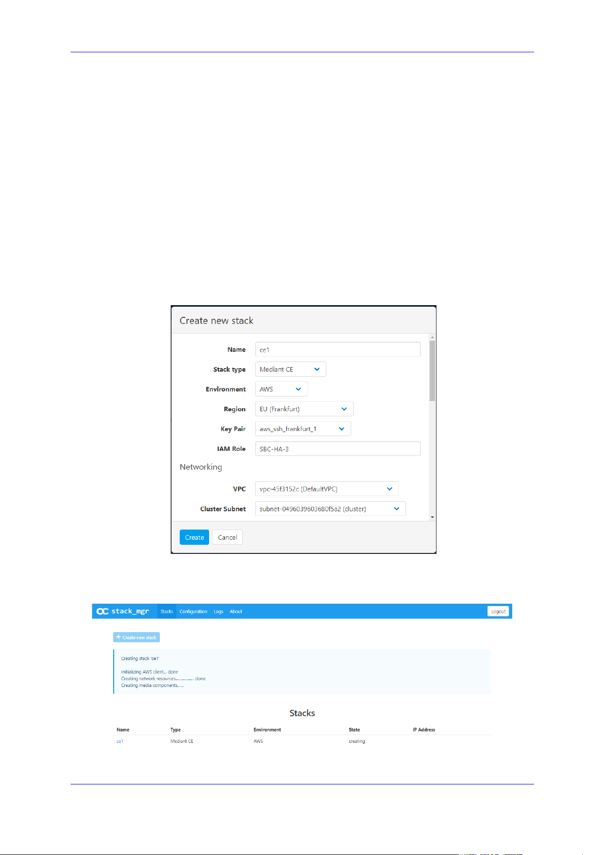
User's Manual 3. Web Interface
Additional Config:
• 'OS Version': Defines the OS version for the deployed SBC software:
♦ 6: This version corresponds to the 7.20A stream.
♦ 8: This version corresponds to the new 7.20CO stream, which provides
significantly better performance and capacity (refer to the SBC-Gateway
Series Release Notes for details) and supports deployment on gen-5
instances (m5/c5/r5).
• 'Management ports': Defines a comma-separated list of inbound ports and
corresponding transport protocols for the management interface, for example,
"22/tcp,80/tcp,443/tcp,161/udp".
• 'Signaling ports': Defines a comma-separated list of inbound ports and
corresponding transport protocols for signaling interfaces, for example,
"5060/udp,5060/tcp,5061/tcp".
• For additional configuration parameters, see Section 3.3.8 Advanced
Configuration.
Figure 3-5: Configuring Mediant CE in AWS Environment
Once you have configured all the above parameters, click Create to create the Mediant CE
stack instance. The operation progress is displayed at the top of the page.
Figure 3-6: Creating Mediant CE in AWS environment
Version 7.4 59 Mediant CE
Page 60

Stack Manager
3.3.1.1 Troubleshooting
The following table lists common problems during Mediant CE stack creation in the AW S
environment and their corresponding solutions.
Table 3-1: Troubleshooting Mediant CE Stack Creation in AWS Environment
Problem Reason Solution
Mediant CE stack creation
freezes at the "Creating media
components" step for more
than 10 minutes. No Media
Component instances are
shown in the AWS dashboard.
You haven't subscribed to the
Mediant VE offer in AWS
Marketplace.
The IAM role specified during
Mediant CE stack creation
doesn’t exist.
Subscribe to Mediant VE offer
in AW S Marketplace, as
described in Mediant Cloud
Edition Installation Manual.
Create an IAM role for Mediant
CE, as described in Mediant
Cloud Edition Installation
Manual and specify its name
in the Mediant CE Create
stack dialog box.
User's Manual 60 Document #: LTRT-28931
Page 61

User's Manual 3. Web Interface
3.3.2 Creating Mediant CE in Azure Environment
The following configuration parameters should be configured (in the Create new stack
dialog) for Mediant CE stack in the Azure environment:
'Name': Defines the stack name, which can contain lowercase or uppercase letters,
digits, and the dash symbol.
'Stack type': Mediant CE.
'Environment': Azure.
'Region': Defines the region where Mediant CE is to be deployed.
Networking:
• 'Virtual Network': Defines the virtual network where Mediant CE is to be deployed.
• 'Cluster Subnet': Defines the subnet used for internal communication between
Mediant CE components.
• 'Main Subnet': Defines the subnet for carrying management traffic (e.g.,
connecting to the Mediant CE Web or SSH interface). The subnet can also be
used for carrying signaling and media traffic.
st
• 1
• ‘Public IPs’: Defines subnets (and corresponding Mediant CE network interfaces)
Media Components:
• 'Profile': Defines the operational mode of MCs (forwarding or transcoding). This
• 'Max Number': Defines the total number of MCs that will be created. It also
• 'Min Number': Defines the number of MCs that will be initially active after Mediant
Admin User:
• 'Username': Defines the username for logging in to the Mediant CE Web or SSH
• 'Password': Defines the password for logging in to the Mediant CE Web or SSH
and 2nd Additional Subnet': Defines additional subnets for carrying signaling
and media traffic. If not needed, leave them as -- none --.
for which Public IPs are assigned.
implicitly determines MC instance types (VM size).
defines the higher boundary for scale-out operation.
CE creation. It also defines the lower boundary for scale-in operation.
interface.
interface.
Note: Azure imposes some limitations on the username and password. For example, it
prohibits the use of "Admin" for username and requires the use of strong passwords that
meet the following policy:
• A minimum of 12 characters.
• Use of three out of four of the following: lowercase characters, uppercase characters,
numbers, and symbols.
Additional Config:
• 'OS Version': Defines the OS version for the deployed SBC software:
♦ 6: This version corresponds to the 7.20A stream.
♦ 8: This version corresponds to the new 7.20CO stream, which provides
significantly better performance and capacity (refer to the SBC-Gateway
Series Release Notes for details).
Version 7.4 61 Mediant CE
Page 62

Stack Manager
• 'Management ports': Defines a comma-separated list of inbound ports and
corresponding transport protocols for the management interface, for example,
"22/tcp,80/tcp,443/tcp,161/udp".
• 'Signaling ports': Defines a comma-separated list of inbound ports and
corresponding transport protocols for signaling interfaces, for example,
"5060/udp,5060/tcp,5061/tcp".
• For additional configuration parameters, see Section 3.3.8 Advanced
Configuration.
Figure 3-7: Configuring Mediant CE in Azure Environment
Once you have configured all the above parameters, click Create to create the Mediant CE
stack instance. The operation progress is displayed at the top of the page.
Figure 3-8: Creating Mediant CE in Azure Environment
Note: If Stack Manager is assigned with custom IAM roles at Subscription, Network and
Resource Group levels, as described in Section 2.8.2.2.2, Option 2: Custom IAM Roles
at Subscription, Network and Resource Group Levels, an empty Resource Group must
be manually created prior to stack deployment and Stack Manager must be assigned with
"Contributor" role in it. The name of this Resource Group must be specified during stack
creation by the Advanced Config parameter resource_group.
User's Manual 62 Document #: LTRT-28931
Page 63

User's Manual 3. Web Interface
the Mediant VE offer in Azure
3.3.2.1 Troubleshooting
The following table lists common problems during Mediant CE stack creation in the Azure
environment and their corresponding solutions.
Table 3-2: Troubleshooting Mediant CE Stack Creation in Azure Environment
Problem Reason Solution
Mediant CE stack creation
fails with error message
"Legal terms have not
been accepted for this item
on this subscription"
Mediant CE stack creation
fails with error message
"Creating resource group
<stack_name> failed”
You haven't subscribed to
Marketplace.
Stack Manager creates a
new Resource Group for
each stack with the same
name as the stack name
(unless resource_group
advanced config parameter
is used). If your subscription
already has such a resource
group, stack creation will fail.
Subscribe to Mediant VE offer in Azure
Marketplace, by deploying a demo
instance of it. Refer to Mediant Cloud
Edition Installation Manual for detailed
description.
Use a different stack name that doesn’t
match the name of any existing
Resource Group in your subscription.
Alternatively, you may configure the
'Name Prefix' parameter in the Stack
Manager configuration screen.
Version 7.4 63 Mediant CE
Page 64

Stack Manager
3.3.3 Creating Mediant CE in Google Cloud Environment
The following configuration parameters should be configured (in the Create new stack
dialog) for Mediant CE stack in Google Cloud environment:
'Name': Defines the stack name, which can contain lowercase or uppercase letters,
digits, and the dash symbol.
'Stack type': Mediant CE.
'Environment': Google.
'Region': Defines the region where Mediant CE is to be deployed.
'Zones': Defines a comma-separated list of two Availability Zones within the specified
Region. Mediant CE components will be evenly spread across these two zones.
'Image': Defines the name of the Mediant VE/CE image. Refer to Mediant Cloud
Edition Installation Manual for detailed instructions on how to upload it to your
account.
Networking:
• 'Cluster Subnet': Defines the subnet used for internal communication between
Mediant CE components.
• 'Main Subnet': Defines the subnet for carrying management traffic (e.g.
connecting to the Mediant CE Web or SSH interface) and signaling traffic. The
subnet can also be used for carrying media traffic.
st
• 1
• ‘Public IPs’: Defines subnets (and corresponding Mediant CE network interfaces)
Media Components:
• 'Profile': Defines the operational mode of MCs (forwarding or transcoding). This
• 'Max Number': Defines the total number of MCs that will be created. It also
• 'Min Number': Defines the number of MCs that will be initially active after Mediant
Admin User:
• 'Username': Defines the username for logging in to the Mediant CE Web or SSH
• 'Password': Defines the password for logging in to the Mediant CE Web or SSH
Additional Config: For additional configuration parameters, see Section 3.3.8
Advanced Configuration.
and 2nd Additional Subnet': Defines additional subnets used for carrying media
traffic. If not needed leave them as -- none --.
for which External IPs are assigned.
implicitly determines MC instance types. Note that the profile must be specified
during Mediant CE creation and cannot be altered afterwards.
defines the higher boundary for scale-out operation.
CE creation. It also defines the lower boundary for scale-in operation.
interface.
interface.
User's Manual 64 Document #: LTRT-28931
Page 65

User's Manual 3. Web Interface
Figure 3-9: Configuring Mediant CE in Google Cloud Environment
Once you have configured all the above parameters, click Create to create the Mediant CE
stack instance. The operation progress is displayed at the top of the page.
Figure 3-10: Creating Mediant CE in Google Cloud Environment
Version 7.4 65 Mediant CE
Page 66

Stack Manager
3.3.4 Creating Mediant CE in OpenStack Environment
The following configuration parameters should be configured (in the Create new stack
dialog) for Mediant CE stack in OpenStack environment:
'Name': Defines the stack name, which can contain lowercase or uppercase letters,
digits, and the dash symbol.
'Stack type': Mediant CE.
'Environment': OpenStack.
'Image': Defines the name of the Mediant VE/CE image. Refer to Mediant Cloud
Edition Installation Manual for detailed instructions on how to upload it to your
account.
'Key Pair': Defines the key pair for logging in to the Mediant CE CLI through SSH.
Alternatively, you can log in using the password specified below.
Networking:
• 'Cluster Subnet': Defines the subnet for internal communication between Mediant
CE components.
• 'Main Subnet': Defines the subnet for carrying management traffic (e.g.,
connecting to the Mediant CE Web or SSH interface). The subnet can also be
used for carrying signaling and media traffic.
st
• '1
• ‘Public IPs’: Defines subnets (and corresponding Mediant CE network interfaces)
Signaling Components:
• 'Flavor': Defines the flavor for SC instances. Refer to Mediant Cloud Edition
Media Components:
• 'Flavor': Defines the flavor for MC instances. Refer to Mediant Cloud Edition
• 'Profile': Defines the operational mode of MCs (forwarding or transcoding). Note
• 'Max Number': Defines the total number of MCs that will be created. It also
• 'Min Number': Defines the number of MCs that will be initially active after Mediant
Admin User:
• 'Username': Defines the username for logging in to the Mediant CE Web or SSH
• 'Password': Defines the password for logging in to the Mediant CE Web or SSH
• Additional Config: For additional configuration parameters, see Section 3.3.8
and 2nd Additional Subnet': Defines additional subnets for carrying signaling
and media traffic. If not needed, leave them as -- none --.
for which Floating IPs are assigned.
Installation Manual for recommended flavors.
Installation Manual for recommended flavors.
that the profile must be specified during Mediant CE creation and cannot be
altered afterwards.
defines the higher boundary for scale-out operation.
CE creation. It also defines the lower boundary for scale-in operation.
interface.
interface.
Advanced Configuration.
User's Manual 66 Document #: LTRT-28931
Page 67

User's Manual 3. Web Interface
Figure 3-11: Configuring Mediant CE in OpenStack Environment
Once you have configured all the above parameters, click Create to create the Mediant CE
stack instance. The operation progress is displayed at the top of the page.
Figure 3-12: Creating Mediant CE in OpenStack Environment
Version 7.4 67 Mediant CE
Page 68

Stack Manager
3.3.5 Creating Mediant VE in Amazon Web Services (AWS) Environment
The following configuration parameters should be configured (in the Create new stack
dialog) for Mediant VE stack in Amazon Web Services (AWS) environment:
'Name': Defines the stack name, which can contain lowercase or uppercase letters,
digits, and the dash symbol.
'Stack type': Mediant VE.
'Environment': AWS.
'Region': Defines the region where Mediant VE is to be deployed.
'Key Pair': Defines the key pair for logging in to the Mediant VE CLI through SSH.
Alternatively, you can log in using the password specified below.
'IAM Role': Defines the name of the IAM role that enables Mediant VE access to AWS
APIs for network reconfiguration in case of SC switchover. Refer to Mediant Virtual
Edition SBC for Amazon AWS Installation Manual for detailed instructions on how to
create it.
Compute:
• 'HA Mode': Defines whether Mediant VE is deployed in HA mode (that includes
two EC2 instances operating in Active/Standby mode) or as a single EC2
instance.
• 'VM Type': Defines instance type used for Mediant VE deployment.
Networking:
• 'VPC': Defines the Virtual Private Cloud where Mediant VE is to be deployed.
• 'HA Subnet': (for HA deployment only) Defines the subnet within the VPC for
internal communication between Mediant VE instances. The subnet must have a
private EC2 endpoint or NAT Gateway configured as the default route. Refer to
Mediant Virtual Edition SBC for Amazon AWS Installation Manual for detailed
instructions on how to create it.
• 'Main Subnet': Defines the subnet within the VPC for carrying management traffic
(e.g., connecting to the Mediant VE Web or SSH interface). The subnet can also
be used for carrying signaling and media traffic.
st
• '1
• ‘Public IPs’: Defines subnets (and corresponding Mediant VE network interfaces)
and 2nd Additional Subnet': Defines additional subnets for carrying signaling
and media traffic. If not needed, leave them as -- none --.
for which Elastic IPs are assigned.
Note: All specified subnets must reside in the same Availability Zone.
Admin User:
• 'Username': Defines the username for logging in to the Mediant VE Web or SSH
interface.
• 'Password': Defines the password for logging in to the Mediant VE Web or SSH
interface.
Additional Config: For additional configuration parameters, see Section 3.3.8
Advanced Configuration.
User's Manual 68 Document #: LTRT-28931
Page 69

User's Manual 3. Web Interface
Figure 3-13: Configuring Mediant VE in AWS Environment
Once you have configured all the above parameters, click Create to create the Mediant VE
stack instance. The operation progress is displayed at the top of the page.
3.3.5.1 Troubleshooting
The following table lists common problems during Mediant VE stack creation in the AWS
environment and their corresponding solutions.
Table 3-3: Troubleshooting Mediant VE Stack Creation in AWS Environment
Problem Reason Solution
Mediant VE stack creation
freezes at the "Creating stack "
step for more than 10 minutes.
No EC2 instances are shown
in the AWS dashboard.
You haven't subscribed to the
Mediant VE offer in AWS
Marketplace.
The IAM role specified during
Mediant VE stack creation
doesn’t exist.
Subscribe to Mediant VE offer
in AWS Marketplace, as
described in Mediant Virtual
Edition SBC for Amazon AWS
Installation Manual.
Create an IAM role for Mediant
VE, as described in Mediant
Virtual Edition SBC for
Amazon AWS Installation
Manual and specify its name
in the Mediant VE Create
stack dialog box.
Version 7.4 69 Mediant CE
Page 70

Stack Manager
3.3.6 Creating Mediant VE in Azure Environment
The following configuration parameters should be configured (in the Create new stack
dialog) for Mediant VE stack in the Azure environment:
'Name': Defines the stack name, which can contain lowercase or uppercase letters,
digits, and the dash symbol.
'Stack type': Mediant VE.
'Environment': Azure.
'Region': Defines the region where Mediant VE is to be deployed.
Compute:
• 'VM Type': Defines VM size used for Mediant VE deployment.
Networking:
• 'Virtual Network': Defines the virtual network where Mediant VE is to be deployed.
• 'Main Subnet': Defines the subnet for carrying management traffic (e.g.,
connecting to the Mediant VE Web or SSH interface). The subnet can also be
used for carrying signaling and media traffic.
st
• 1
• ‘Public IPs’: Defines subnets (and corresponding Mediant VE network interfaces)
Admin User:
• 'Username': Defines the username for logging in to the Mediant VE Web or SSH
• 'Password': Defines the password for logging in to the Mediant VE Web or SSH
and 2nd Additional Subnet': Defines additional subnets for carrying signaling
and media traffic. If not needed, leave them as -- none --.
for which Public IPs are assigned
interface.
interface.
Note: Azure imposes some limitations on the username and password. For example, it
prohibits the use of "Admin" for username and requires the use of strong passwords that
meet the following policy:
• A minimum of 12 characters.
• Use of three out of four of the following: lowercase characters, uppercase characters,
numbers, and symbols.
User's Manual 70 Document #: LTRT-28931
Page 71

User's Manual 3. Web Interface
the Mediant VE offer in Azure
Additional Config: For additional configuration parameters, see Section 3.3.8
Advanced Configuration.
Figure 3-14: Configuring Mediant VE in Azure Environment
Once you have configured all the above parameters, click Create to create the Mediant VE
stack instance. The operation progress is displayed at the top of the page.
3.3.6.1 Troubleshooting
The following table lists common problems during Mediant VE stack creation in the Azure
environment and their corresponding solutions.
Table 3-4: Troubleshooting Mediant VE Stack Creation in Azure Environment
Problem Reason Solution
Mediant VE stack creation
fails with the error
message "Legal terms
have not been accepted
for this item on this
subscription".
You haven't subscribed to
Marketplace.
Subscribe to Mediant VE offer in Azure
Marketplace by deploying a demo
instance of it. Refer to Mediant Virtual
Edition SBC for Azure Installation
Manual for detailed description.
Version 7.4 71 Mediant CE
Page 72

Stack Manager
3.3.7 Creating Mediant VE in Google Cloud Environment
The following configuration parameters should be configured (in the Create new stack
dialog) for Mediant CE stack in Google Cloud environment:
'Name': Defines the stack name, which can contain lowercase or uppercase letters,
digits, and the dash symbol.
'Stack type': Mediant VE.
'Environment': Google.
'Region': Defines the region where Mediant VE is to be deployed.
'Zones': Defines a comma-separated list of two Availability Zones within the specified
Region. Mediant VE components will be evenly spread across these two zones.
'Image': Defines the name of the Mediant VE/CE image. Refer to Mediant Virtual
Edition for Google Cloud Installation Manual for detailed instructions on how to upload
it to your account.
Compute:
• 'HA Mode': Defines whether Mediant VE is deployed in HA mode (that includes
two VM instances operating in Active/Standby mode) or as a single VM instance.
• 'VM Type': Defines machine type used for Mediant VE deployment.
Networking:
• 'HA Subnet': (for HA deployment only) Defines the subnet used for internal
communication between Mediant VE components.
• 'Main Subnet': Defines the subnet for carrying management traffic (e.g.
connecting to the Mediant VE Web or SSH interface) and signaling traffic. The
subnet can also be used for carrying media traffic.
st
• 1
• ‘Public IPs’: Defines subnets (and corresponding Mediant VE network interfaces)
Admin User:
• 'Username': Defines the username for logging in to the Mediant VE Web or SSH
• 'Password': Defines the password for logging in to the Mediant VE Web or SSH
and 2nd Additional Subnet': Defines additional subnets used for carrying media
traffic. If not needed leave them as -- none --.
for which External IPs are assigned.
interface.
interface.
User's Manual 72 Document #: LTRT-28931
Page 73

User's Manual 3. Web Interface
Additional Config: For additional configuration parameters, see Section 3.3.8
Advanced Configuration.
igure 3-15: Configuring Mediant VE in Google Cloud Environment
Once you have configured all the above parameters, click Create to create the Mediant VE
stack instance. The operation progress is displayed at the top of the page.
3.3.8 Advanced Configuration
The Create new stack dialog includes the Advanced Config group that can be used to
specify advanced configuration parameters during stack creation.
Specify parameters using the following format:
<parameter name> = <value>
You can specify multiple parameters on multiple lines.
Figure 3-16: Advanced Configuration Parameters
Version 7.4 73 Mediant CE
Page 74

Stack Manager
sc_ha_mode = disable
3.3.8.1 Advanced Configuration for Mediant CE
The following table describes advanced parameters available for Mediant CE.
Table 3-5: Advanced Parameters Description
Parameter
Applicable
Description
Environment
sc_ha_mode All Defines the number of SCs.
Supported values:
enable (default): Two SCs are created and
operate in 1+1 HA mode.
disable: One SC is created.
Example:
sc_public_ips All Defines the SC's network interface names for which
public IP addresses are allocated and optionally, the
number of corresponding IP addresses.
During stack creation (via Web interface), Stack
Manager lets you specify which subnets (and
corresponding network interfaces) will be assigned
with public (Elastic) IP addresses using the Public
IPs parameter in the Networking section.
When the sc_public_ips advanced configuration
parameter is specified, it overrides any value
configured by the Public IPs parameter. You will
typically use this parameter when:
You need to create multiple IP addresses on the
same network interface.
You need to configure IP addresses differently for
Signaling and Media Components.
Syntax: comma-separated list of interface names.
Interface names are specified by corresponding
subnet names: “main”, “additional1”, “additional2”.
You may also use “all” to specify all interfaces. If
more than one public IP address is required on the
specific network interface, this may be specified as
“<name>:<num>”, where <num> is the total number
of public IP addresses to be created. Legacy
interface names – “ethX” – are deprecated, but still
supported.
Examples:
sc_public_ips = main,additional1:2
sc_public_ips = main:2
Notes:
In Azure, network interfaces listed in this
parameter are placed behind the Public Load
Balancer.
In Google Cloud, only the “main” interface is
supported and is placed behind the Network Load
Balancer.
User's Manual 74 Document #: LTRT-28931
Page 75

User's Manual 3. Web Interface
Stack Manager implicitly creates all private IP
be specified as “<name>:<num>”, where <num> is
Parameter Applicable
Description
Environment
addresses required for public IP address
assignment
mc_public_ips All Defines the MC's network interface names for which
public IP addresses are allocated and optionally, the
number of corresponding IP addresses.
During stack creation (via Web interface), Stack
Manager lets you specify which subnets (and
corresponding network interfaces) will be assigned
with public (Elastic) IP addresses using the Public
IPs parameter in the Networking section.
When the mc_public_ips advanced configuration
parameter is specified, it overrides any value
configured by the Public IPs parameter. You will
typically use this parameter when:
You need to create multiple IP addresses on the
same network interface.
You need to configure IP addresses differently for
Signaling and Media Components.
Syntax: comma-separated list of interface names.
Interface names are specified by corresponding
subnet names: “main”, “additional1”, “additional2”.
You may also use “all” to specify all interfaces. If
more than one public IP address is required on the
specific network interface, this may be specified as
“<name>:<num>”, where <num> is the total number
of public IP addresses to be created. Legacy
interface names – “ethX” – are deprecated, but still
supported.
Examples:
mc_public_ips = main,additional1:2
mc_public_ips = main:2
Notes:
Stack Manager implicitly creates all private IP
addresses required for public IP address
assignment.
sc_additional_ips All Defines the SC's network interface names for which
additional private IP addresses are allocated and
optionally, the number of corresponding IP
addresses.
Additional IP addresses are allocated on top of any
private IP addresses created by Stack Manager by
default and/or due to the public IP addresses
assigned to the specific network interface.
Syntax: comma-separated list of interface names.
Interface names are specified by corresponding
subnet names: “main”, “additional1”, “additional2”.
You may also use “all” to specify all interfaces. If
more than one additional private IP address is
required on the specific network interface, this may
Version 7.4 75 Mediant CE
Page 76

Stack Manager
the total number of additional private IP addresses to
main,additional1:2
Parameter Applicable
Environment
mc_additional_ips All
Description
be created. Legacy interface names – “ethX” – are
deprecated, but still supported.
Examples:
sc_additional_ips = additional1
sc_additional_ips =
main,additional1:2
Note:
In Azure, network interfaces listed in this
parameter are placed behind the Internal Load
Balancer.
In Google Cloud, only the “main” interface is
supported and is placed behind the Internal Load
Balancer.
Defines the MC's network interface names for which
additional private IP addresses are allocated and
optionally, the number of corresponding IP
addresses.
Additional IP addresses are allocated on top of any
private IP addresses created by Stack Manager by
default and/or due to the public IP addresses
assigned to the specific network interface.
Syntax: comma-separated list of interface names.
Interface names are specified by corresponding
subnet names: “main”, “additional1”, “additional2”.
You may also use “all” to specify all interfaces. If
more than one additional private IP address is
required on the specific network interface, this may
be specified as “<name>:<num>”, where <num> is
the total number of additional private IP addresses to
be created. Legacy interface names – “ethX” – are
deprecated, but still supported.
Examples:
mc_additional_ips = additional1
mc_additional_ips =
oam_ip Azure Defines which of the IP addresses on the “eth1”
User's Manual 76 Document #: LTRT-28931
network interface, connected to the main subnet, is
used for management traffic (Web, SSH, or SNMP).
Syntax:
“default”: use the primary IP address on the
“eth1” network interface, connected to the main
subnet, for management traffic;
If the public IP address is assigned to the
main subnet, the primary IP address resides
behind the Public Load Balancer and
therefore, Mediant CE management should
be performed via Load Balancer’s public IP
address.
Page 77

User's Manual 3. Web Interface
If the public IP address is not assigned to the
sc_num_of_interfaces = 2
mc_num_of_interfaces = 2
sc_instance_type = Standard_DS3_v2
Parameter Applicable
Environment
Description
main subnet, the primary IP address resides
behind the Internal Load Balancer and
therefore, Mediant CE management should
be performed via Load Balancer’s internal IP
address.
“internal”: if the “eth1” network interface,
connected to the main subnet, has a secondary
IP address that resides behind the Internal Load
Balancer, use this IP address for Mediant CE
management.
For example, the following configuration:
sc_public_ips = main
sc_additional_ips = main
oam_ip = internal
creates two IP addresses on the “eth1” network
interface, connected to the main subnet:
“eth1” – primary IP address, placed behind the
Public Load Balancer and used for SIP traffic.
“eth1:1” – secondary IP address, placed behind
the Internal Load Balancer and used for
management traffic (Web, SSH, or SNMP).
sc_num_of_interfaces All Defines the number of network interfaces for SCs.
mc_num_of_interfaces All Defines the number of network interfaces for MCs.
sc_instance_type All Defines the instance type (virtual machine size /
By default, all components (SCs and MCs) are
connected to all subnets specified during stack
creation. If you want some subnets to be connected
to MCs only, use this parameter to reduce the
number of network interfaces for SCs.
Example:
By default, all components (SCs and MCs) are
connected to all subnets specified during stack
creation. If you want some subnets to be connected
to SCs only, use this parameter to reduce the
number of network interfaces for MCs.
Example:
flavor) for SCs.
Refer to the Mediant Cloud Edition Installation
Manual for a list of officially supported and
recommended instance types. Contact AudioCodes
support if you want to use a different instance type
and to verify that this configuration is allowed and
supported.
Example:
Version 7.4 77 Mediant CE
Page 78

Stack Manager
mc_instance_type = c4.2xlarge
sc_image_id = rg1/image1
sc_image_id = rg1/image1
sc1_ha_name = sc-1
sc2_ha_name = sc-2
sc_tags = sbc,sc
Parameter Applicable
Description
Environment
mc_instance_type All Defines the instance type (virtual machine size /
flavor) for MCs.
Refer to the Mediant Cloud Edition Installation
Manual for a list of officially supported and
recommended instance types. Contact AudioCodes
support if you want to use a different instance type
and to verify that this configuration is allowed and
supported.
Example:
sc_image_id AWS
Azure
Defines the local image for SCs (instead of the
default Marketplace image).
Syntax:
AWS: AMI ID
Azure: Resource Group name / image name
Examples:
sc_image_id = ami-9a50cff5
mc_image_id AWS
Azure
Defines the local image for MCs (instead of the
default Marketplace image).
Syntax:
AWS: AMI ID
Azure: Resource Group name / image name
Examples:
sc_image_id = ami-9a50cff5
sc1_ha_name All
Defines the name of the first SC on the Web
interfaces Monitor page.
Example:
sc2_ha_name All Defines the name of the second SC on the Web
interfaces Monitor page.
Example:
sc_tags AWS, Azure,
Google
Assigns tags to SCs.
Syntax:
AWS or Azure: comma-separated list of
name=value pairs
Google: comma-separated list of tags
Examples:
sc_tags = type=sbc,role=sc
mc_tags AWS, Azure,
Google
Assigns tags to MCs.
Syntax:
AWS or Azure: comma-separated list of
name=value pairs
User's Manual 78 Document #: LTRT-28931
Page 79

User's Manual 3. Web Interface
Google: comma-separated list of tags
mc_tags = sbc,mc
availability_zones = 1,2
StandardSSD_LRS
Parameter Applicable
Description
Environment
Examples:
mc_tags = type=sbc,role=mc
sc_ini_params All Defines additional configuration parameters (in INI
file format) for SCs.
Syntax: multiple lines can be specified using \n as a
line delimiter.
Example:
sc_ini_params = EnableSyslog =
1\nSyslogServerIP = 10.1.2.3
Note: Use with caution and do not overwrite the
default INI configuration parameters created by
Stack Manager.
mc_ini_params All Defines additional configuration parameters (in INI
file format) for MCs.
Syntax: multiple lines can be specified using \n as a
line delimiter.
Note: Use with caution and do not overwrite the
default INI configuration parameters created by
Stack Manager.
availability_zones Azure Defines the deployment topology for the Azure
environment.
Syntax:
“auto” (default): Mediant CE components are
deployed into a single Proximity Placement
Group with two Availability Sets (each containing
two fault and update domains) for Signaling and
Media Components, respectively. This
deployment topology minimizes network latency
between Mediant CE components while still
providing adequate redundancy at the
infrastructure level.
comma-separated list of two zone names (e.g.,
“1,2”): Deployed Mediant CE components are
evenly spread across the specified two
Availability Zones. Note that such deployment
topology may suffer from intermittent network
latency between zones, which may affect internal
communication between Mediant CE components
and cause SC/MC switchovers.
Examples:
availability_zones = auto
storage_account_type Azure Defines the storage account type for managed disks.
Valid values include:
Standard_LRS
Premium_LRS
Version 7.4 79 Mediant CE
Page 80

Stack Manager
Example:
storage_account_type = Premium_LRS
resource_group = SbcGroup1
diag_account = rg1/account1
cluster_nsg_id = rg1/cluster-nsg
oam_nsg_id = rg1/oam-nsg
Parameter Applicable
Description
Environment
resource_group Azure Defines the name of the existing Resource Group.
If not empty, stack resources will be deployed into
this Resource Group instead of creating a new one.
The Resource Group must be empty prior to stack
creation.
Example:
diag_account Azure Defines the name of the existing Storage Account.
If not empty, the specified Storage Account is used
to store VM’s diagnostics data instead of creating a
new one.
Syntax: Resource Group name / account name
Example:
cluster_nsg_id AWS, Azure Defines the name of the existing Network Security
Group (NSG) to be used on SC and MC interfaces
connected to the Cluster Subnet, instead of creating
a new one.
Refer to the Default Security Rules chapter in the
Mediant CE Installation Manual for a detailed list of
rules that should be included in the Cluster NSG.
Syntax:
AWS: Security Group ID
Azure: Resource Group name / NSG name
cluster_nsg_id = sg-11223344
oam_nsg_id AWS, Azure Defines the name of the existing Network Security
Group (NSG) to be used on SC interfaces connected
to the Main Subnet, instead of creating a new one.
Refer to the Default Security Rules chapter in the
Mediant CE Installation Manual for a detailed list of
rules that should be included in the OAM NSG.
Make sure that OAM NSG includes rules that enable
Stack Manager to access deployed SBC instances
using the HTTPS protocol (TCP/443).
In an Azure environment, OAM NSG should include
both management and signaling rules. In an AWS
environment, OAM NSG should include only
management rules, as both OAM NSG and Signaling
NSG are assigned to the SC interfaces connected to
the Main subnet.
Syntax:
AWS: Security Group ID
Azure: Resource Group name / NSG name
oam_nsg_id = sg-22334455
User's Manual 80 Document #: LTRT-28931
Page 81

User's Manual 3. Web Interface
signaling_nsg_id = rg1/signaling-nsg
media_nsg_id = rg1/media-nsg
spot_instances = enable
disable
Parameter Applicable
Description
Environment
signaling_nsg_id AWS, Azure
Defines the name of the existing Network Security
Group (NSG) to be used on SC interfaces connected
to Additional1/2 Subnets, instead of creating a new
one.
Refer to the Default Security Rules chapter in the
Mediant CE Installation Manual for a detailed list of
rules that should be included in the Signaling NSG.
Syntax:
AWS: Security Group ID
Azure: Resource Group name / NSG name
signaling_nsg_id = sg-33445566
media_nsg_id AWS, Azure Defines the name of the existing Network Security
Group (NSG) to be used on MC interfaces
connected to Main and Additional1/2 Subnets,
instead of creating a new one.
Refer to the Default Security Rules chapter in the
Mediant CE Installation Manual for a detailed list of
rules that should be included in the Media NSG.
Syntax:
AWS: Security Group ID
Azure: Resource Group name / NSG name
media_nsg_id = sg-44556677
spot_instances Azure Enables the use of Azure Spot instances for testing
environments. Keep in mind that Spot instances may
be abruptly stopped and therefore, should never be
used in production environment.
Supported values:
enable: use Spot instances
disable (default): use regular instances
Example:
use_proximity_
placement_group
Azure Defines if deployed components are placed in the
proximity placement group.
Supported values:
enable (default): use proximity placement group
disable: do not use proximity placement group
Example:
use_proximity_placement_group =
use_placement_group AWS Defines if deployed components are placed in the
placement group.
Supported values:
enable (default): use placement group
disable: do not use placement group
Version 7.4 81 Mediant CE
Page 82

Stack Manager
Example:
use_placement_group = disable
mc_max_pps_limit = 280
manage_via_https = disable
auto_start_time = 08:00
auto_stop_time = 22:00
oam_subnet_cidr = 10.2.3.0/24
Parameter Applicable
Description
Environment
mc_max_pps_limit All Defines the maximum Media Component’s
forwarding capacity in packets per second.
Supported values:
auto (default): Stack Manager automatically
configures MC forwarding capacity based on the
cloud environment and instance type used
<number>: manually defines MC forwarding
capacity
Example:
manage_via_https All Defines the protocol used by the Stack Manager
when connecting to the deployed stack’s
management interface.
Supported values:
enable (default): use HTTPS protocol
disable: use HTTP protocol
Example:
auto_start_time All Defines time of day when stack automatically starts.
Supported syntax:
08:00 – time of day (24h)
1/08:00 – weekday (0=Sunday, 1=Monday, …,
6=Saturday) and time
0,1,2/08:00 – multiple weekdays and time
0-5/08:00 – range of weekdays and time
0,1/08:00|2-4/09:00 – multiple statements
Example:
auto_stop_time All Defines time of day when stack will be automatically
stopped.
Syntax is identical to auto_start_time parameter.
Example:
oam_subnet_cidr,
main_subnet_cidr,
additional1_subnet_cidr,
additional2_subnet_cidr
Azure Defines the CIDR for a specific subnet. This may be
used to override automatic subnet CIDR detection or
to overcome Stack Manager’s lack of permissions to
read current subnet configuration.
Syntax: Subnet IP / Prefix Length.
Example:
User's Manual 82 Document #: LTRT-28931
Page 83

User's Manual 3. Web Interface
the total number of additional private IP addresses to
3.3.8.2 Advanced Configuration for Mediant VE
The following table describes advanced parameters available for Mediant VE.
Table 3-6: Advanced Parameters Description
Parameter Applicable
Environment
public_ips All Defines the SC's network interface names for which
public IP addresses are allocated and optionally, the
number of corresponding IP addresses.
During stack creation (via Web interface), Stack
Manager lets you specify which subnets (and
corresponding network interfaces) will be assigned
with public (Elastic) IP addresses using the Public
IPs parameter in the Networking section.
When the public_ips advanced configuration
parameters is specified, it overrides any value
configured by the Public IPs parameter. You will
typically use this parameter when you need to create
multiple IP addresses on the same network
interface.
Syntax: comma-separated list of interface names.
Interface names are specified by corresponding
subnet names: “main”, “additional1”, “additional2”.
You may also use “all” to specify all interfaces. If
more than one public IP address is required on the
specific network interface, this may be specified as
“<name>:<num>”, where <num> is the total number
of public IP addresses to be created. Legacy
interface names – “ethX” – are deprecated, but still
supported.
Examples:
public_ips = main,additional1:2
public_ips = main:2
Notes:
Stack Manager implicitly creates all private IP
addresses required for public IP address
assignment
Description
additional_ips All Defines the network interface names for which
Version 7.4 83 Mediant CE
additional private IP addresses are allocated and
optionally, the number of corresponding IP
addresses.
Additional IP addresses are allocated on top of any
private IP addresses created by Stack Manager by
default and/or due to the public IP addresses
assigned to the specific network interface.
Syntax: comma-separated list of interface names.
Interface names are specified by corresponding
subnet names: “main”, “additional1”, “additional2”.
You may also use “all” to specify all interfaces. If
more than one additional private IP address is
required on the specific network interface, this may
be specified as “<name>:<num>”, where <num> is
Page 84

Stack Manager
be created. Legacy interface names – “ethX” – are
additional_ips = main,additional1:2
image_id = rg1/image1
tags = sbc,sc
spot_instances = enable
manage_via_https = disable
Parameter Applicable
Environment
image_id AW S
Azure
tags AWS,
Google
Description
deprecated, but still supported.
Examples:
additional_ips = additional1
Defines the local image for SCs (instead of the
default Marketplace image).
Syntax:
AWS: AMI ID
Azure: Resource Group name / image name
Examples:
image_id = ami-9a50cff5
Assigns tags to created instances.
Syntax:
AWS: comma-separated list of name=value pairs
Google: comma-separated list of tags
Examples:
tags = type=sbc,role=sc
ini_params All Defines additional configuration parameters (in INI
file format) for created instances.
Syntax: multiple lines can be specified using \n as a
line delimiter.
Example:
ini_params = EnableSyslog =
1\nSyslogServerIP = 10.1.2.3
Note: Use with caution and do not overwrite the
default INI configuration parameters created by
Stack Manager.
spot_instances Azure Enables use of Azure spot instances for testing
environments. Keep in mind that spot instances may
be abruptly stopped and therefore should never be
used in production environment.
Supported values:
enable: use spot instances
disable (default): use regular instances
Example:
manage_via_https All Defines the protocol used by the Stack Manager
when connecting to the deployed stack’s
management interface
Supported values:
enable (default): use HTTPS protocol
disable: use HTTP protocol
Example:
User's Manual 84 Document #: LTRT-28931
Page 85

User's Manual 3. Web Interface
auto_start_time = 08:00
auto_stop_time = 22:00
Parameter Applicable
Description
Environment
auto_start_time All
Defines the time of day when stack automatically
starts.
Supported syntax:
08:00 – time of day (24h)
1/08:00 – weekday (0 is Sunday, 1 is Monday, 2
is Tuesday and so on) and time
0,1,2/08:00 – multiple weekdays and time
0-5/08:00 – range of weekdays and time
0,1/08:00|3-5/09:00 – multiple statements
Example:
auto_stop_time All Defines time of day when stack automatically stops.
The syntax is identical to the auto_start_time
parameter.
Example:
Version 7.4 85 Mediant CE
Page 86

Stack Manager
3.4 Checking Stack State and Configuration
To check the state and configuration of the existing stack, open the Stacks page and then
click the specific stack. The Stack Information page is displayed, which allows you to check
the current stack state, inspect and modify its configuration, and perform actions such as
scale-out, scale-in, and delete the stack if it’s no longer needed.
Figure 3-17: Stack Information Page
User's Manual 86 Document #: LTRT-28931
Page 87

User's Manual 3. Web Interface
3.5 Active Alarms
Stack Manager periodically checks the state of all created stacks and raises alarms if it
discovers any problem. Active alarms are displayed in Stacks summary screen and in the
detailed Stack Information page.
Figure 3-18: Active Alarms in Stacks Summary Screen
Figure 3-19: Active Alarms in Stack Information Page
The following alarms are supported:
rest-api: The alarm is raised when Stack Manager can't read the status of Mediant
VE/CE via REST API
mc-status: The alarm is raised when Stack Manager can't read the status of Mediant
CE's Media Components via REST API.
mc-X-down: The alarm is raised when Media Component mc-X is not in service
(alarm description provides detailed Media Component state).
mc-X-missing: The alarm is raised when Media Component mc-X is missing from
Mediant CE's configuration and Stack Manager can't fix it.
sc-X-down: The alarm is raised when Signaling Component sc-X is down.
sc-ha-alarm: The alarm is raised when Signaling Components are not in HA
synchronized state
To avoid false alarms, most of the alarms are raised only after the problem persists for 5
minutes.
Version 7.4 87 Mediant CE
Page 88

Stack Manager
3.6 Performing Operations on Stack
You can perform operations on the running stack (e.g., Scale Out), by clicking the
corresponding button on the toolbar of the Stack Information page.
All operations, except for Delete and Heal, are serialized and can be performed one at a
time. For example, if you started the Scale Out operation, you have to wait until it completes
prior to starting the Scale In operation.
The stack state is updated accordingly when an operation is being performed.
User's Manual 88 Document #: LTRT-28931
Page 89

User's Manual 3. Web Interface
3.7 Scaling Mediant CE Stack
Note: This section is applicable only to Mediant CE stacks.
The number of active MCs in the Mediant CE stack may vary to match the required service
capacity. This is called scaling and ensures that the stack utilizes the optimal amount of
resources at any point of time and elastically scales on demand. An operation that increases
the amount of active MCs is called Scale Out; an operation that decreases the amount of
active MCs is called Scale In.
To ensure fast and reliable scaling, Stack Manager pre-creates all needed MCs in advance
(up to the maximum number) and stops/starts them accordingly during scale in/out
operations.
Scaling decision can be triggered either manually—by running the Scale In, Scale Out or
Scale To commands—or automatically based on the current cluster utilization.
The size of the cluster is configured by the following two configuration parameters:
Minimum Number of Media Components
Maximum Number of Media Components
3.7.1 Scale Out Operation
The Scale Out operation increases the number of MCs in the Mediant CE stack, by starting
additional pre-created "idle" MCs (for example, corresponding to the AWS EC2 instance
state changes from stopped to running).
You must specify the number of MCs to add to the service. Alternatively, you may specify
names of MCs that will be added to the service (e.g., "mc-3,mc-4").
Figure 3-20: Scale Out Operation
The Scale Out operation is not allowed when Automatic Scaling is enabled. Use the Scale
To operation instead.
Version 7.4 89 Mediant CE
Page 90

Stack Manager
3.7.2 Scale In Operation
The Scale In operation decreases the number of MCs in the Mediant CE stack, by stopping
a certain number of "active" MCs (for example, corresponding to the AWS EC2 instance
state changes from running to stopped).
You must specify the number of MCs to be removed from the service. Alternatively, you may
specify names of MCs that will be removed from the service (e.g., "mc-3,mc-4").
Figure 3-21: Scale In Operation
The Scale In operation is not allowed when Automatic Scaling is enabled. Use the Scale To
operation instead.
3.7.3 Scale To Operation
The Scale To operation sets the number of MCs in the Mediant CE stack to the specified
value. It essentially performs a Scale In or Scale Out operation, depending on the current
stack state.
Figure 3-22: Scale To Operation
In contrast to Scale In and Scale Out operations, the Scale To operation is allowed when
Automatic Scaling is enabled. Regardless of whether it adds or removes MCs, for the
purposes of calculating a cool down period, the Scale To operation is considered to be
equivalent to the Scale Out operation. This means that the cluster size may be increased
immediately after completing the Scale To command, if needed.
User's Manual 90 Document #: LTRT-28931
Page 91

User's Manual 3. Web Interface
3.8 Automatic Scaling
Note: This section is applicable only to Mediant CE stacks.
Automatic Scaling adjusts the Mediant CE cluster size to the current service needs, by
measuring current cluster utilization and changing its size accordingly. It is implemented by
a background job performed by the Stack Manager.
For every stack that is in "running" state and has Automatic Scaling enabled, Stack Manager
calculates the total amount of "free" media and DSP resources, using accumulative
percentage points, where 100% corresponds to the capacity of a single MC. For example,
for a cluster that is in the following state:
+------+---------------+-----------+--------+------+
| id | IP address | status | %media | %dsp |
+------+---------------+-----------+--------+------+
| mc-1 | 172.31.78.116 | connected | 30 | 0 |
| mc-2 | 172.31.75.42 | connected | 40 | 0 |
| mc-3 | 172.31.65.5 | connected | 25 | 0 |
+------+---------------+-----------+--------+------+
Free media resources are calculated as follows:
free_media = (100-30) + (100-20) + (100-25) = 205 %
Note: The calculated number is the number of excessive MCs capacity in the Mediant
CE cluster. For example, 100% corresponds to the state where the total amount of
excessive capacity equals the capacity of a single MC. In this state, the failure of a single
MC has no effect on traffic capacity, thus providing N+1 redundancy for the media
cluster.
The calculated number is then compared against Scale In and Scale Out Thresholds, which
are defined in the stack configuration. If the number is below the Scale Out Threshold, the
Scale Out operation is triggered. If the number is above the Scale In Threshold, the Scale In
operation is triggered.
It is possible to disable media or DSP thresholds, by setting them to 0 (zero).
If both media and DSP thresholds are used, the decision is made as follows:
Scale Out is performed when either media or DSP utilization is below the threshold
Scale In is performed when both media and DSP utilization are above the threshold
Maximum / Minimum Number of Media Components parameters define the maximum /
minimum cluster size, and automatic scaling mechanism takes them into account when
making its decisions.
Automatic scaling logs are collected in the auto-job log, which can be viewed through Web
or CLI management interfaces:
$ stack_mgr log --name auto_job --lines 10
Version 7.4 91 Mediant CE
Page 92

Stack Manager
300% of media resources in stack 'stack1' are unused
MEDIA_UTIL_SCALE_IN_THRESHOLD is 250
Trigger automatic scale in
Choosing SBC media components to be removed...... done
Preparing SBC media component 'mc-3' for removal.... done
Initializing AWS client... done
Updating SBC cluster configuration.... done
Removing SBC media components............................. done
3.8.1 Cool Down Period
To prevent stack size 'bouncing', the Automatic Scaling Cool Down Time parameter defines
the minimum time (in seconds) between consecutive Scale Out and Scale In decisions.
3.8.2 Auto Scale Step
The number of MCs to be added or removed by the automatic scaling mechanism can be
configured using the Automatic Scaling Scale-In / Scale-Out Step parameters.
Both parameters are set to 1 by default, thus enabling Automatic Scaling to add or remove
one MC at a time. If you change the Automatic Scaling Scale-Out Step parameter to a
greater value (e.g., 2), your stack size will grow quickly to adjust to traffic demands, but will
shrink slowly when traffic is reduced.
3.8.3 Changing Cluster Size at Specific Time of Day
In certain scenarios, service capacity is typically expected to change at certain times of day.
For example, if the Contact Center starts to operate at 9:00 AM, it would be reasonable to
expect that SBC traffic will surge at that time.
It is possible to change Mediant CE scaling while having Automatic Scaling enabled, using
one of the following methods:
Changing the Minimum Number of Media Components parameter, which defines the
minimum cluster size
Defining the target cluster size by the Scale To operation
If you choose to define the target cluster size by the Scale To operation, keep in mind that
the cool-down period is calculated as if the Scale Out operation was performed. Therefore,
cluster size will grow immediately if required and will not be reduced for the cool-down period
even if traffic hasn’t started yet.
The corresponding operations may be programmed to run at a specified time of day using
CLI and the cron scheduler. Make sure that commands are run by the stack_mgr user, and
replace the stack_mgr command with the expression "/usr/bin/python3
/opt/stack_mgr/bin/stack_mgr.py". For example:
$ cat /var/stack_mgr/scale_to.sh
#!/bin/bash
STACK_MGR="/usr/bin/python3 /opt/stack_mgr/bin/stack_mgr.py"
$STACK_MGR scale $1 -n $2 >> /var/log/stack_mgr/cron.log
$ cat /etc/cron.d/stack_mgr
* 9 * * * stack_mgr /var/stack_mgr/scale_to.sh stack1 10
User's Manual 92 Document #: LTRT-28931
Page 93

User's Manual 3. Web Interface
3.9 Modifying Stack Configuration
To modify configuration of the existing Mediant VE/CE stack, open the Stack information
page, and then click the Modify button on the toolbar to open the Modify stack dialog box.
Change stack configuration parameters as desired, and then click Modify to apply your
changes.
Figure 3-23: Modifying Stack Configuration
Most of the parameters are applied immediately and have no adverse effect on service.
However, change of some parameters may require an additional Update operation and may
be service affecting. Such parameters are explicitly marked in the Modify screen and the
detailed description is provided at the screen footnote.
Version 7.4 93 Mediant CE
Page 94

Stack Manager
Figure 3-24: Modify Screen Footnote
Figure 3-25: Modifying Parameter that Requires Update
User's Manual 94 Document #: LTRT-28931
Page 95

User's Manual 3. Web Interface
3.9.1 Update Operation
The Update operation updates the stack to the new configuration. It is required when
modified configuration requires applying some changes to the underlying virtual
infrastructure resources, for example, when you resize the cluster.
The need to do an Update operation is indicated in the Modify operation output and on the
Stack information page:
Figure 3-26: Stack in "Update Needed" State
Click the Update button on the toolbar to start the Update operation and wait until it
completes.
Note: The Update operation may be service affecting. It is therefore recommended to
run it during a maintenance period.
Version 7.4 95 Mediant CE
Page 96

Stack Manager
Figure 3-27: Updating Stack Configuration
3.9.2 Modifiable Parameters for Mediant CE
The following table lists all stack configuration parameters that can be modified.
Table 3-7: Modifiable Stack Configuration Parameters
Group Name Parameter Applicable
Environment
General
Automatic
scaling
Minimum number of media
components
Maximum number of media
components
Automatic scaling All No No
Media utilization scale in
threshold
Media utilization scale out
threshold
DSP utilization scale in threshold All No No
DSP utilization scale out
threshold
Automatic scaling cool down
time
All No No
All Yes No
All No No
All No No
All No No
All No No
Requires
Update
Service
Affecting
Automatic scaling scale-in step All No No
Automatic scaling scale-out step All No No
Signaling
Components
User's Manual 96 Document #: LTRT-28931
Number of network interfaces
Interfaces with public IP AW S, Azure,
AWS, Azure,
Google
Google
Yes Yes
Yes Yes
Page 97

User's Manual 3. Web Interface
Group Name Parameter Applicable
Environment
Interfaces with additional IP
AWS, Azure,
Requires
Update
Yes Yes
Google
Management ports AWS, Azure,
Yes No
Google
Signaling ports AWS, Azure,
Yes No
Google
Instance type AWS, Azure,
Yes Yes
Google
Media
Components
Number of network interfaces AWS, Azure,
Google
Interfaces with public IP
AWS, Azure,
Yes Yes
Yes
Google
Interfaces with additional IP AW S, Azure,
Yes
Google
Instance type AWS, Azure,
Yes Yes
Google
Profile AWS, Azure,
Yes Yes
Google
Network
Subnets
Additional 1 subnet AWS, Azure,
Google
Additional 2 subnet AWS, Azure,
No
No
Google
Advanced OS version Azure Yes
Advanced config All Yes
Affecting
(1)
No
(1)
No
(3)
Yes
(2)
Yes
Service
(1)
(1)
(3)
(2)
Comments All No No
(1) Modification of additional subnets is allowed only when they are not in use
(2) Modification of ‘advanced config’ parameters requires Rebuild operation and is limited
to the following parameters: manage_via_https, mc_max_pps_limit, sc_image_id,
mc_image_id, spot_instances, storage_account_type, oam_ip, private_ip_*, public_ip_*
(3) Modification of the ‘OS version’ parameter requires an Update operation, during which
all VMs are rebuilt. During this operation, the serial number of signaling components
changes and therefore, their local license will be invalidated. You need to obtain, activate
and apply the new license to the signaling components to restore the service.
Version 7.4 97 Mediant CE
Page 98

Stack Manager
3.9.3 Modifiable Parameters for Mediant VE
The following table lists all stack configuration parameters that can be modified.
Table 3-8: Modifiable Stack Configuration Parameters
Group Name Parameter Applicable
Environment
Requires
Update
Service
Affecting
Compute Instance type All Yes Yes
Networking Number of network interfaces
AWS, Azure,
Yes Yes
Google
Interfaces with public IP AW S, Azure,
Yes Yes
Google
Interfaces with additional IP AW S, Azure,
Yes Yes
Google
Additional 1 subnet AWS, Azure,
No
(1)
No
Google
Additional 2 subnet AWS, Azure,
No
(1)
No
Google
Advanced OS version Azure Yes
Advanced config All Yes
(3)
Yes
(2)
Yes
Comments All No No
(1) Modification of additional subnets is allowed only when they are not in use.
(2) Modification of ‘advanced config’ parameters requires Rebuild operation and is limited
to the following parameters: manage_via_https, image_id, spot_instances,
storage_account_type, private_ip_*, public_ip_*
(1)
(1)
(3)
(2)
(3) Modification of the ‘OS version’ parameter requires an Update operation, during which
all VMs are rebuilt. During this operation, the serial number of components changes and
therefore, their local license will be invalidated. You need to obtain, activate and apply
the new license to the components to restore the service.
User's Manual 98 Document #: LTRT-28931
Page 99

User's Manual 3. Web Interface
3.10 Stopping and Starting Stack
If you want to temporarily stop all Mediant CE components (e.g., in a lab environment) use
the Stop operation. Use the Start operation afterwards to return all components back to
service.
Figure 3-28: Stopping Stack
3.11 Healing Stack
The Heal operation verifies the state of all stack components and fixes any errors if detected.
For example, it can remove MCs that are not properly registered in the SCs or remove
orphaned entries from the "Media Components" configuration table.
The command is typically used after Stack Manager is interrupted in the middle of some
operation, for example, during stack creation or Scale Out. It can also be useful when the
output of some operation (e.g., Scale In) indicates an intermittent failure.
In most cases, Stack Manager heals itself automatically (see the following section). However,
in some cases, manual healing is needed to ensure that the stack state matches its
configuration.
Figure 3-29: Healing Stack
Version 7.4 99 Mediant CE
Page 100

Stack Manager
3.11.1 Automatic Healing
Stack Manager automatically triggers a Heal operation when it detects that an operation
(e.g., Scale In or Scale Out) was interrupted.
In addition to the above, for stacks that have Automatic Healing enabled, the operational
state of all components is periodically monitored and Stop, Start or Rebuild operations are
triggered if needed.
The automatic healing logs are collected in the auto-job log, which can be viewed through
the Web or CLI management interfaces.
3.12 Deleting Stack
The Delete operation deletes the stack and releases all resources allocated during its
creation.
Figure 3-30: Deleting a Stack
3.13 Upgrading Software on Idle Media Components
Note: This section is applicable only to Mediant CE stacks.
Upgrading the MCs software is done through the Web interface (Setup > IP Network >
Cluster Manager Settings > Start Upgrade), as described in the Mediant Software User’s
Manual. However, this is applicable only to "active" MCs.
To complete upgrade for "idle" MCs (that are in "stopped" state), click the More > Update
Idle MCs button on the toolbar.
The operation temporarily starts "idle" MCs, waits until they complete software upgrade, and
then shuts them down.
3.14 Rebuilding Stack
The Rebuild operation rebuilds specific stack components. The command is typically used
when specific stack components stop operating correctly and their operation cannot be
restored through regular backup/restore procedures.
Component names must be explicitly specified as the Rebuild operation parameter, for
example:
sc-1: Rebuilds the first SC instance
mc-1,mc-2: Rebuilds the first two MC instances
sc: Rebuilds all SC instances
mc: Rebuilds all MC instances
sbc-1: Rebuilds the first Mediant VE instance
User's Manual 100 Document #: LTRT-28931
 Loading...