

Page 1

ADR-32
Digital Audio Router
Te chnical
Manual
DECEMBER 2002
Page 2

ADR-32 Digital Audio Router Technical Manual - 1st EditionADR-32 Digital Audio Router Technical Manual - 1st Edition
ADR-32 Digital Audio Router Technical Manual - 1st Edition
ADR-32 Digital Audio Router Technical Manual - 1st EditionADR-32 Digital Audio Router Technical Manual - 1st Edition
©2002 Audioarts® Engineering*
(*a division of Wheatstone Corporation)
R-16 / Dec 1997
ADR-32 / Dec 2002
AUDIOARTS ENGINEERING
600 Industrial Drive
New Bern, North Carolina 28562
252-638-7000
Page 3
Attention!
FF
ederal Communications Commission (FCC) Complianceederal Communications Commission (FCC) Compliance
F
ederal Communications Commission (FCC) Compliance
FF
ederal Communications Commission (FCC) Complianceederal Communications Commission (FCC) Compliance
Notice:Notice:
Notice:
Notice:Notice:
Radio FRadio F
Radio F
Radio FRadio F
NOTE:NOTE:
NOTE: This equipment has been tested and found to comply with the
NOTE:NOTE:
limits for a Class A digital device, pursuant to Part 15 of the FCC rules. These
limits are designed to provide reasonable protection against harmful
interference when the equipment is operated in a commercial environment.
This equipment, generates, uses and can radiate radio frequency energy
and, if not installed and used in accordance with the instruction manual,
may cause harmful interference to radio communications. Operation of this
equipment in a residential area is likely to cause harmful interference in
which case the user will be required to correct the interference at his own
expense.
requency Noticerequency Notice
requency Notice
requency Noticerequency Notice
AA
TTENTIONTTENTION
A
TTENTION
TTENTIONTTENTION
AA
This is Class A product. In a domestic environment, thisThis is Class A product. In a domestic environment, this
This is Class A product. In a domestic environment, this
This is Class A product. In a domestic environment, thisThis is Class A product. In a domestic environment, this
product may cause radio interference, in which case, theproduct may cause radio interference, in which case, the
product may cause radio interference, in which case, the
!
This equipment must be installed and wired properly in order to assure
compliance with FCC regulations.
Caution!Caution!
Caution!
Caution!Caution!
Wheatstone Corporation could void the user's authority to operate thisWheatstone Corporation could void the user's authority to operate this
Wheatstone Corporation could void the user's authority to operate this
Wheatstone Corporation could void the user's authority to operate thisWheatstone Corporation could void the user's authority to operate this
equipment.equipment.
equipment.
equipment.equipment.
product may cause radio interference, in which case, theproduct may cause radio interference, in which case, the
user may be required to take appropriate measures.user may be required to take appropriate measures.
user may be required to take appropriate measures.
user may be required to take appropriate measures.user may be required to take appropriate measures.
Any modifications not expressly approved in writing by Any modifications not expressly approved in writing by
Any modifications not expressly approved in writing by
Any modifications not expressly approved in writing by Any modifications not expressly approved in writing by
ADR-32 / Dec 2002
RR
R
RR
EADEAD
EAD
EADEAD
M M
M
M M
!!
EE
E
!
EE
!!
Page 4

CONTENTS
ADR-32
Technical Manual
Table of Contents
Chapter 1 – General Information
Unpacking the Router...................................................................1-2
Introduction ...................................................................................1-2
Power Supply ................................................................................1-3
Audio Connections .......................................................................1-3
Digital Audio Connections ........................................................................................ 1-3
Unbalanced Analog Connections ............................................................................. 1-4
Unbalanced Digital Connections (SPDIF) ................................................................ 1-4
Hand Crimp Tool Wiring Instructions .........................................1-5
Chapter 2 - Hardware
Overview ........................................................................................2-3
Configuration Guidelines ..........................................................2-4
Audio I/O Expansion............................................................................................. 2-4
Digital Input Card (SRC-8)
Overview .....................................................................................2-5
AES Input Interface....................................................................2-5
Internal Programming Options .................................................2-5
SPDIF 75Ω Termination ....................................................................................... 2-6
Hook-Ups ....................................................................................2-6
DB Pinout Drawing ....................................................................2-8
Analog Input Card (ADC-4)
Overview .....................................................................................2-9
Analog Input Interface ...............................................................2-9
Internal Programming Options ....................................................2-9
Hook-Ups ...................................................................................2-10
Analog Audio Connections .................................................................................. 2-10
Mono Inputs ......................................................................................................... 2-10
DB Pinout Drawing ...................................................................2-11
ADR-32 / Dec 2002
page Contents – 1
Page 5

CONTENTS
Digital Output Card (DO-8)
Overview ....................................................................................2-12
AES Output Interface................................................................2-12
AES Channel Status Implementation......................................2-13
Internal Programming Options ................................................2-13
Hook-Ups ...................................................................................2-13
DB Pinout Drawing ...................................................................2-15
Analog Output Card (AO-4)
Overview ....................................................................................2-16
Analog Output Interface ...........................................................2-16
Internal Programming Options ................................................2-16
Hook-Ups ...................................................................................2-16
Analog Audio Connections .................................................................................. 2-17
Mono Outputs ...................................................................................................... 2-17
External Mono Summing ..................................................................................... 2-18
DB Pinout Drawing ...................................................................2-19
Monitor Output & Speaker Mute
Overview ....................................................................................2-20
Hook-Ups ...................................................................................2-20
DB Pinout Drawing ...................................................................2-21
CPU
Overview ....................................................................................2-22
CPU BIOS Settings/Format ......................................................2-22
Ethernet IP Addressing ............................................................2-22
Ethernet Interface Wiring .........................................................2-23
Internal Programming Options ................................................2-23
Switch Settings .........................................................................2-23
DIPSW1-SW4 - 485 Termination ........................................................................ 2-23
DIPSW6 pos 1 - AES Sync Out Channel Status................................................. 2-24
DIPSW6 pos 2 - Autodetect................................................................................. 2-24
Jumper Settings........................................................................2-24
J3-J10 - Determines XY Controller ID#............................................................... 2-24
Serial Interface Ports ................................................................2-25
Hook-Ups
“CONSOLE I/O” DB-9 - Serial Interface Port Connections................................. 2-25
“XYC I/O” DB-9 - Serial Interface Port Connections ........................................... 2-25
RJ-45 - Ethernet Connections ............................................................................. 2-25
Typical Ethernet Cable .............................................................2-26
Typical Crossover Cable ..........................................................2-26
DB Pinout Drawing ...................................................................2-27
ADR-32 / Dec 2002
page Contents – 2
Page 6

CONTENTS
Chapter 3 - Controller Devices
XP Configuration GUI ...................................................................3-2
XY Controller GUI..........................................................................3-3
XY Rack Controller........................................................................3-3
Console XY Controller ..................................................................3-4
XY Controller Settings ..................................................................3-4
Setting an XY Controller Termination....................................................................... 3-4
Setting an XY Controller Address............................................................................. 3-4
XY Controller Signal Visibility......................................................3-5
XY Controller RS-485 Connections .............................................3-5
Overview ................................................................................................................... 3-5
Serial Port Note ........................................................................................................ 3-6
Cable Wiring ............................................................................................................. 3-6
Typical RS-485 Cable Specifications ..........................................3-6
XY Controller RS-485 Cable Pinouts ...........................................3-7
Wheatstone Console Interface.....................................................3-8
?
Wheatstone Console RS-485 Connections.................................3-8
Console RS-485 Cable Pinouts....................................................3-8
Console CPU Module Settings.....................................................3-9
Console Address ...................................................................................................... 3-9
RS-485 Select / Termination .................................................................................... 3-9
.....................................................................................................................................
Chapter 4 - XPoint Software Setup Guide
ADR-32 Ethernet/IP Address Quick Start....................................4-2
Ethernet Cabling ....................................................................................................... 4-2
Default IP Address.................................................................................................... 4-2
Changing your PC’s IP Address ............................................................................... 4-2
Changing the ADR-32’s IP Address ......................................................................... 4-2
Configuring IP Address in X-Point Software ............................................................ 4-3
Saving the ADR-32 Configuration ............................................................................ 4-3
Getting Started ..............................................................................4-4
GUI Log-In......................................................................................4-4
Passwords ................................................................................................................ 4-4
Tier Configuration .........................................................................4-5
Connection Between the Configuration GUI and ADR-32.........4-6
Signal Definition............................................................................4-9
?
Important Signal Definition Notes ..............................................4-9a
Signal Locking..............................................................................4-10
Salvo Definition ............................................................................4-11
XY Rack or Console XY Controller Configuration ....................4-12
ADR-32 / Dec 2002
ADR-32 / Jun 2003
page Contents – 3
Page 7

CONTENTS
Console Configuration ............................................................ 4-13
Special Functions - Console Locks ......................................................................4-13
Console Presets ................................................................................................... 4-13
XY GUI Controller Configuration ............................................ 4-14
Saving and Loading Configurations .................................... 4-14a
Off-line Editing ....................................................................................................4-14a
Sending a Configuration to the ADR-32 ............................................................. 4-14a
Main Menu Summary ............................................................... 4-15
Chapter 5 - I/O Schematic Drawings
4 Analog Inputs Card Schematic (ADC-4) ............................................................ 5-2
4 Analog Inputs Card Load Sheet (ADC-4)........................................................... 5-4
4 Analog Outputs Card Schematic (AO-4) ............................................................ 5-5
4 Analog Outputs Card Load Sheet (AO-4) .......................................................... 5-7
8 Digital Inputs Card Schematic (SRC-8).............................................................. 5-8
8 Digital Outputs Card Load Sheet (SRC-8) .......................................................5-10
8 Digital Outputs Card Schematic (DO-8) ........................................................... 5-11
8 Digital Outputs Card Load Sheet (DO-8) ......................................................... 5-12
Processor Board Schematic (PR-32) ..................................................................5-13
Processor Board Load Sheet (PR-32)................................................................. 5-18
Glossary
Terminology............................................................................... G-1
Appendices
Appendix 1
Configuring the ADR-32 Network Parameters.........................A-3
Appendix 2
Replacement Parts List .............................................................A-6
ADR-32 / Dec 2002
ADR-32 / Jun 2003
page Contents – 4
Page 8

GENERAL INFORMATION
General Information
Chapter Contents
Unpacking the Router...................................................................1-2
Introduction ...................................................................................1-2
Power Supply ................................................................................1-3
Audio Connections .......................................................................1-3
Digital Audio Connections ........................................................................................ 1-3
Unbalanced Analog Connections ............................................................................. 1-4
Unbalanced Digital Connections (SPDIF) ................................................................ 1-4
Hand Crimp Tool Wiring Instructions .........................................1-5
ADR-32 / Dec 2002
page 1 – 1
Page 9
GENERAL INFORMATION
General Information
Unpacking the Router
The ADR-32 Router is shipped as one package, which contains the router,
X-Point CD, and technical manual.
Introduction
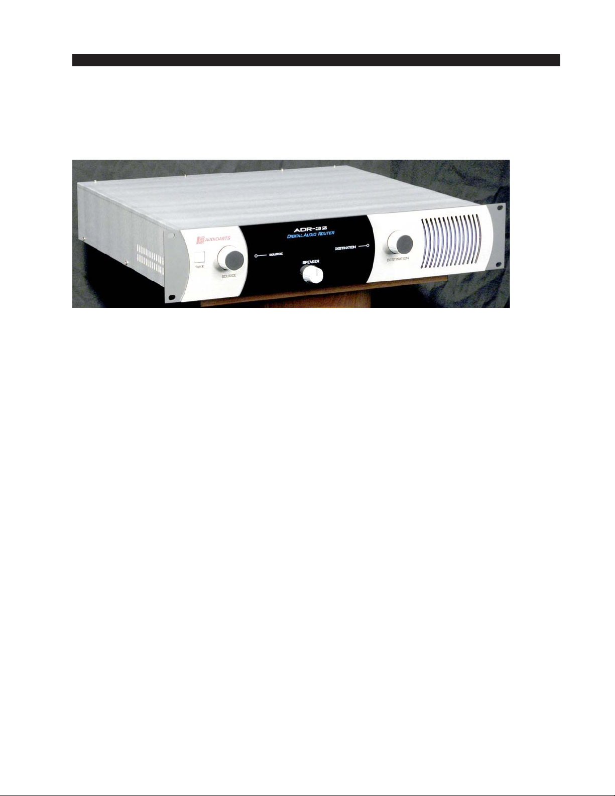
The ADR-32 Digital Audio Router is a rackmount unit occupying two 19”
wide rack spaces (total height 3.5”) with 16” depth.
The ADR-32 accepts up to 32 discrete analog stereo or digital audio inputs
in Audio Engineering Society (AES) format, and switches them to any of 32
stereo analog or digital outputs.
The ADR-32 cage may be fitted with up to 8 input and 8 output cards.
ADR-32 / Dec 2002
page 1 – 2
Page 10
GENERAL INFORMATION
Power Supply
The ADR-32 is powered by a built-in Audioarts Model SPS-32
switching power supply, located under a metal cover. This power
supply contains high voltage circuits that are hazardous and potentially harmful. Under no circumstances should the metal cover be
removed! If you have a problem with the power supply, the ADR-32
unit must be returned to Wheatstone Corporation for repair.
The power supply wires to the 9-pin power connector CT18 or
CT19 on the PR-32 PCB with wire gauge 16AWG as shown below:
Pin 1 [WHT]: +5V Digital
Pin 2 [ORG]: +5V Digital
Pin 3 [BRN]: Digital Ground
Pin 4 [BLK]: Analog Ground
Pin 5 [GRN]: Digital Ground
Pin 6 [BLU]: -V
Pin 7 [BLK]: Analog Ground
Pin 8 [VIO]: +Phantom
Pin 9 [RED]: +V
Connect the console’s power cord to a clean 90V - 240V AC outlet
(that is, an AC source that feeds only the control room audio gear).
Note: each power supply is fitted with a 3-wire grounded AC cord
that should be plugged into a "clean" AC power source. This source
should be a separate feed from those powering lighting, air-conditioning, or any other non-audio machinery. The third pin ground wire of the
AC source should be tied to the central system ground point.
The optional external failsafe power supply is also available.
Consult factory for further information.
Audio Connections
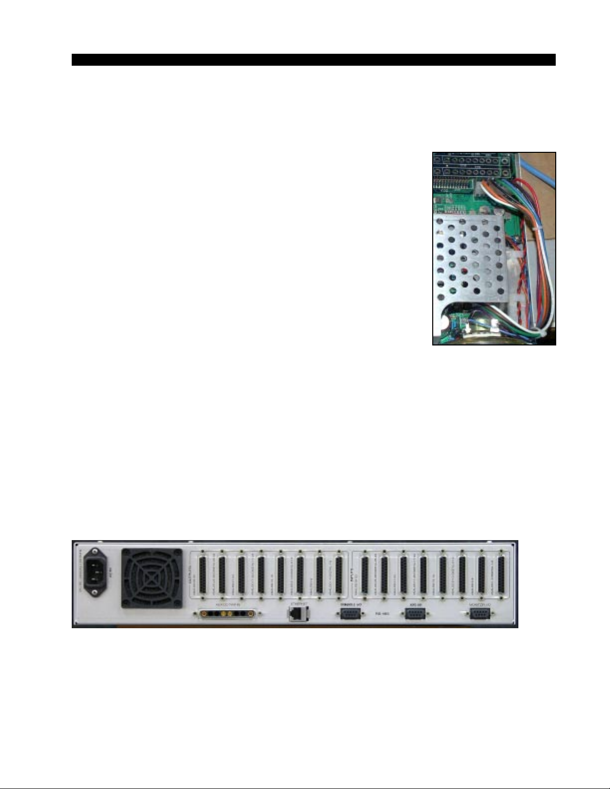
All audio connections to the ADR-32 are made through multipin
DB-25 and DB-9 connectors located on the cage rear.
The factory supplied hand crimping tool is used for all I/O wiring
connections to and from the router (see instruction on the page 1-5).
Digital Audio Connections
CABLE - All AES/EBU input and output digital audio connections
are balanced and should be made using a high quality digital audio
cable. Be sure to select a digital audio cable with an integral drain wire
ADR-32 / Dec 2002
page 1 – 3
Page 11

GENERAL INFORMATION
of the same wire gauge (AWG) as the twisted pair as this facilitates an
easier and consistent termination process. Typical AES/EBU digital audio
cable has a very low characteristic capacitance per ft (pF/ft), and a nominal
impedance of 110Ω. High quality digital audio cable offers better signal
transmission performance versus typical analog audio cable, especially
over long cable runs. Check the cable manufactures data sheet to be sure
the cable you plan to use will work in your application.
CONNECTORS - Typically, all AES/EBU connections are made with
the supplied DB-25 male mating connectors. These crimp style connectors
will accept wire gauge 22 - 28AWG.
Unbalanced Analog Connections
ANALOG INPUTS — Wire to the switcher input end with typical
shielded, two conductor cable (like Belden 9451), just as if you were
connecting a balanced source. At the unbalanced source machine’s output,
connect the + output to the HI input wire and connect the source machine
GND wire to LO, connect the shield at the balanced end only .
Note: Unbalanced analog sources typically have -10dBv (316mV RMS)
signal levels and will not match the ADR-32 nominal operating level of
+4dBu (1.23V RMS). We highly recommended that you first externally
balance any unbalanced sources you plan on connecting to the ADR-32.
Many third party “match boxes” are commercially available for this.
ANALOG OUTPUTS — Use an electronically balanced output circuit
which behaves exactly like the secondary of a high-quality transformer,
with no center tap—this output is both balanced and floating. For unbalanced operation, either the HI or LO side of the analog output must be
strapped to ground of the unbalanced input, with the output taken from the
other side. (Normally you would strap LO to ground, and use HI to feed
your unbalanced equipment input.) Leave the SH floating at the balanced
end.
Unbalanced Digital Connections (SPDIF)
SPDIF INPUTS - The SPDIF (Sony/Philips Digital Interface) or
“consumer” digital audio interface is a two wire unbalanced signal
typically on a single RCA style connector. We highly recommend using
a “balun” or format converter when interfacing “consumer” grade source
devices to the ADR-32.
In cases where a consumer grade device must be interfaced and the
appropriate matching device is not available, try wiring the SPDIF center
conductor (HOT) to the HI input pin and SPDIF shell (ground) to the LO
input. Connect SH at the ADR-32 router end only. To correctly match the
SPDIF signal level of approximately 500mV and 75 ohm impedance to the
ADR-32 AES inputs, be sure to set the appropriate internal 75Ω termina-
tion dipswitch on the digital input card.
SPDIF OUTPUTS - The ADR-32 digital outputs are fixed, professional, AES-3 formatted outputs. SPDIF consumer format is not supported. Use an external format converter to connect the digital outputs to
consumer gear.
ADR-32 / Dec 2002
page 1 – 4
Page 12
GENERAL INFORMATION
HAND CRIMP TOOL WIRING INSTRUCTIONS
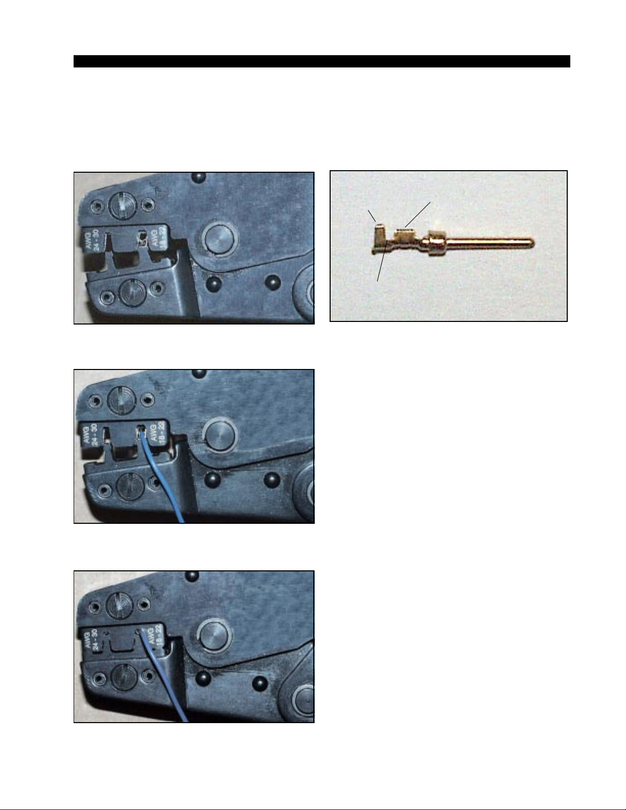
The supplied hand crimping tool (W/S#850067) is used for all I/O wiring connections to and from the console. It is to be used with the supplied pin (figure 1)
intended for 22"-28" gauge wire.
(2) The terminal conductor tabs (pointing UP) are
placed in anvil 18-22; the terminal's insulation tabs
extend in front towards the camera.
Insulation
stops here
(3) The stripped wire is placed into the terminal and
crimped. Note the wire's insulation must stop just
short of the conductor tabs (detail)
INSULATION
TABS
INSULATION
STOPS HERE
CONDUCTOR
TABS
(1) Pin crimp terminal
1) Strip wire approximately 3/16" (insert in
proper wire stripper, rotate one half turn, and
pull insulation off wire).
2) Leaving wire aside for the moment, with
crimping tool fully open (engraved side toward
you) bring a terminal into position from the
unmarked side of the tool. Place the conductor
tabs (inner set as shown in figure 1) on the
"18-22" or "24-30" (depending on the wire) anvil (slightly curved surface) so that the circular
portion of the tabs rests in the curved surface
of the anvil and the two tabs face up into the
walls of the female jaw. The insulation tabs will
be flush with the top of the tool (figure 2).
3) Close tool very slightly, only to the point
of holding the terminal in position (figure 2).
4) Insert wire into terminal until wire insulation is stopped by conductor tabs (figure 3).
CRIMP by squeezing handles until jaws are fully
closed (figure 4).
5) If there is an insertion error or if a circuit
change is needed, you'll need to use an extractor tool to remove terminals (see next page).
Note that metallized plastic hoods for each
connector are also supplied with the router.
(4) Final step: jaws fully closed; the insulation tabs
have been crimped.
ADR-32 / Dec 2002
ADR-32 / Jun 2004
page 1 – 5
Page 13
GENERAL INFORMATION
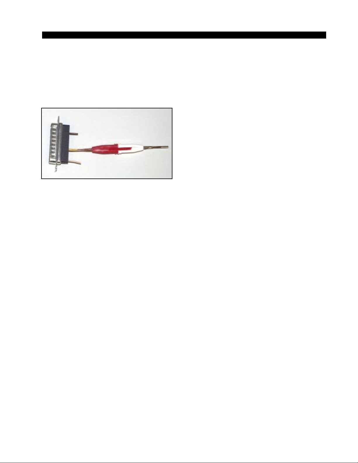
EXTRACTOR PIN INSTRUCTIONS
(5) Place extractor tip over pin terminal to be
removed.
If you accidentally insert a crimp terminal
pin into the wrong socket, you'll need to use
the supplied pin extractor tool (W/S#850069)
to remove terminal pin, and correct your mistake without having to sacrifice a connector.
Place extractor tip (red side) over terminal pin
to be removed (figure 5), and press it downwards motion until tip rests upon Housing.
Then pull out the terminal pin from Housing.
It should never be necessary to discard a connector due to a wiring error.
ADR-32 / Dec 2002
ADR-32 / Jun 2004
page 1 – 6
Page 14

HARDWARE
Hardware
Chapter Contents
Overview ........................................................................................2-3
Configuration Guidelines ..........................................................2-4
Audio I/O Expansion............................................................................................. 2-4
Digital Input Card (SRC-8)
Overview .....................................................................................2-5
AES Input Interface....................................................................2-5
Internal Programming Options .................................................2-5
SPDIF 75Ω Termination ....................................................................................... 2-6
Hook-Ups ....................................................................................2-6
DB Pinout Drawing ....................................................................2-8
Analog Input Card (ADC-4)
Overview .....................................................................................2-9
Analog Input Interface ...............................................................2-9
Internal Programming Options ....................................................2-9
Hook-Ups ...................................................................................2-10
Analog Audio Connections .................................................................................. 2-10
Mono Inputs ......................................................................................................... 2-10
DB Pinout Drawing ...................................................................2-11
Digital Output Card (DO-8)
Overview ....................................................................................2-12
AES Output Interface................................................................2-12
AES Channel Status Implementation......................................2-13
Internal Programming Options ................................................2-13
Hook-Ups ...................................................................................2-13
DB Pinout Drawing ...................................................................2-15
Analog Output Card (AO-4)
Overview ....................................................................................2-16
Analog Output Interface ...........................................................2-16
Internal Programming Options ................................................2-16
Hook-Ups ...................................................................................2-16
Analog Audio Connections .................................................................................. 2-17
Mono Outputs ...................................................................................................... 2-17
External Mono Summing ..................................................................................... 2-18
DB Pinout Drawing ...................................................................2-19
ADR-32 / Dec 2002
page 2 – 1
Page 15

HARDWARE
Monitor Output & Speaker Mute
Overview ....................................................................................2-20
Hook-Ups ...................................................................................2-20
DB Pinout Drawing ...................................................................2-21
CPU
Overview ....................................................................................2-22
CPU BIOS Settings/Format ......................................................2-22
Ethernet IP Addressing ............................................................2-22
Ethernet Interface Wiring .........................................................2-23
Internal Programming Options ................................................2-23
Switch Settings .........................................................................2-23
DIPSW1-SW4 - 485 Termination ........................................................................ 2-23
DIPSW6 pos 1 - AES Sync Out Channel Status................................................. 2-24
DIPSW6 pos 2 - Autodetect................................................................................. 2-24
Jumper Settings........................................................................2-24
J3-J10 - Determines XY Controller ID#............................................................... 2-24
Serial Interface Ports ................................................................2-25
Hook-Ups
“CONSOLE I/O” DB-9 - Serial Interface Port Connections................................. 2-25
“XYC I/O” DB-9 - Serial Interface Port Connections ........................................... 2-25
RJ-45 - Ethernet Connections ............................................................................. 2-25
Typical Ethernet Cable .............................................................2-26
Typical Crossover Cable ..........................................................2-26
DB Pinout Drawing ...................................................................2-27
ADR-32 / Dec 2002
page 2 – 2
Page 16
HARDWARE
Hardware
Overview
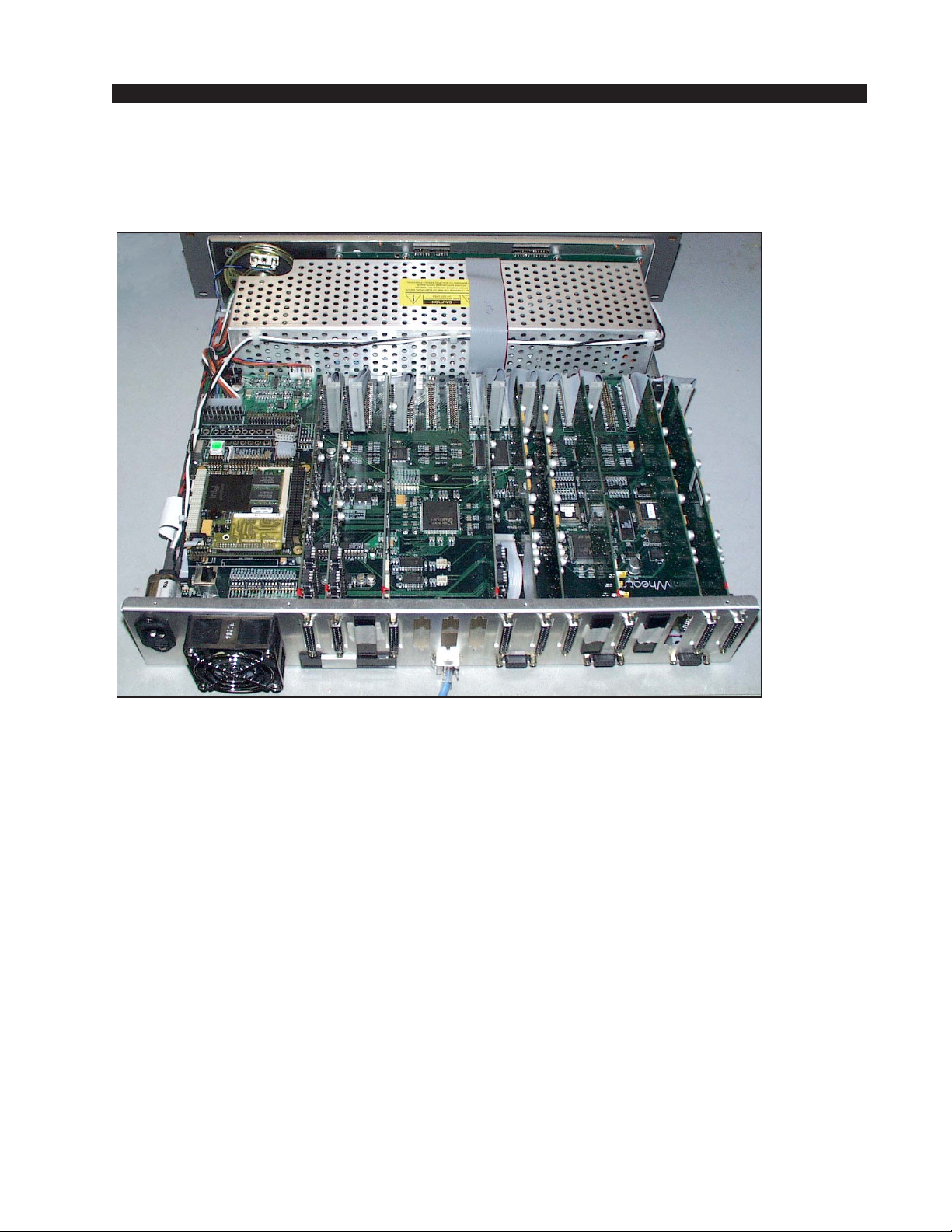
The ADR-32 may be configured for a variety of I/O card complements
using various combinations of analog and digital audio input and output
cards. All audio input and output signal connections are made via multipin
DB-25 connectors located on the cage rear and mounted on the input/output
daughter cards. The input/output daughter cards plug into the PR-32 board
connectors (CT20-CT35). The AUX DC power supply, monitor, serial
control, and ethernet connections are also made on the rear of cage.
ADR-32 / Dec 2002
page 2 – 3
Page 17
HARDWARE
Configuration Guidelines
While the ADR-32 router is pre-configured to customer specifications
at Wheatstone’s factory, future expansion of a system may require some
re-configuration of existing hardware to accommodate new resources.
Audio input cards may be mounted in slots 1 through 8 (counting right
to left if you are looking from cage rear), and output cards may be mounted
in slots 9 through 16. Digital input and output cards each handle eight
inputs/outputs, while analog input and output cards each handle four
inputs/outputs. The ADR-32 can support up to four digital input cards and
four digital output cards, or up to eight analog input cards and eight analog
output cards. Digital and analog cards can be freely mixed, subject to
correct placement, as described below. However, the card complement
can not exceed 32 inputs or 32 outputs.
Audio I/O Expansion
The ADR-32 supports a maximum of 32 stereo input channels and 32
stereo output channels.
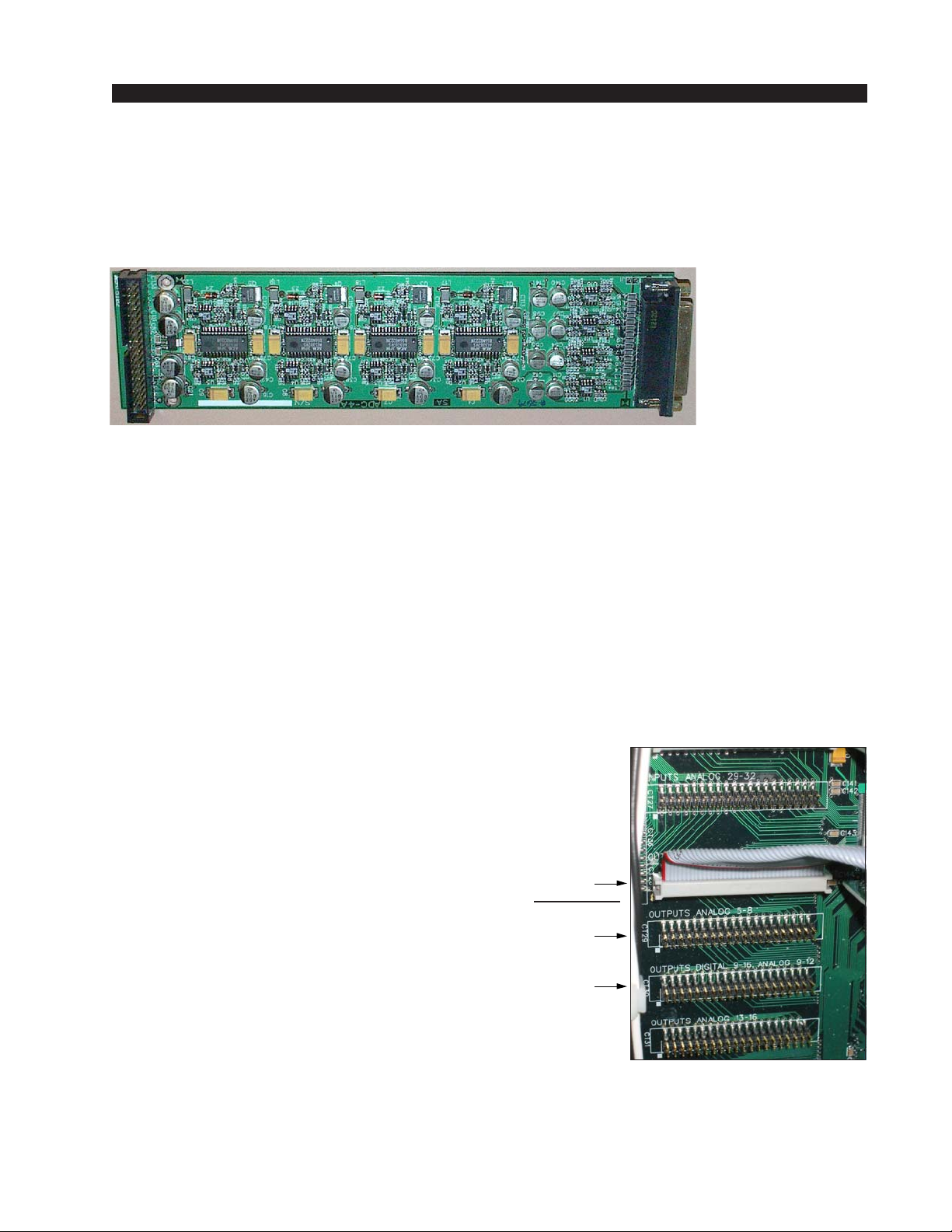
•Power down by removing AC cord.
• Removing the cover - Remove the 14 - #4/32
1/4” Phillips head screws located along the sides
and top of the ADR-32 chassis.
• Locating an available slot - Find the next
available input or output slot 40 pin header on the
motherboard. Be careful to note the silkscreen
labelling along side each connector. Some headers
will only work with analog I/O cards, other headers work with both analog and digital I/O cards. In
placing cards, it may be helpful to think in terms of
slot pairs. That is, the input section contains eight
Analog Out
1-4 installed
Add only
Analog Out
5 - 8 here
or
Add Digital Out
9-16 or
Analog Out 9-12
here
slots, or four slot pairs, and the same is true of the
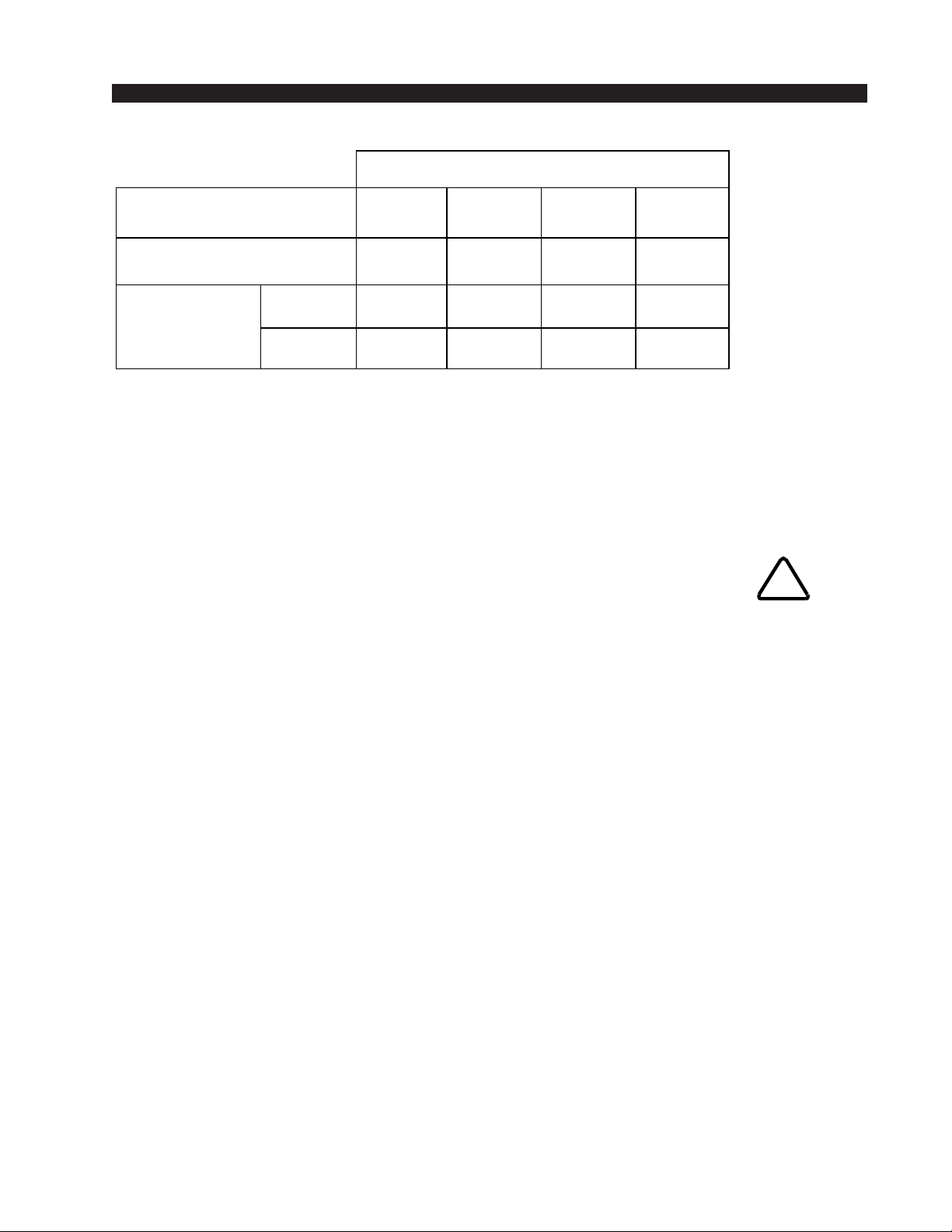
output section. For the first output pair, the following table shows the allowed card combinations for
that pair. The same concept applies to the other output slot pairs, and to
the input slot pairs.
Example
ADR-32 / Dec 2002
page 2 – 4
Page 18
HARDWARE
ALLOWED CARD COMBINATIONS
FIRST SLOT OF PAIR
DIGITAL 1-8 OR ANALOG 1-4
SECOND SLOT OF PAIR
ANALOG 5-8
TOTAL SIGNALS
HANDLED IN
SLOT PAIR
ANALOG
DIGITAL
ANALOG
[1-4]
EMPTY
448Ø
ØØØ8
EMPTY
ANALOG
[5-8]
ANALOG
[1-4]
ANALOG
[5-8]
DIGITAL
[1-8]
EMPTY
Please note these important points:
° each slot pair can have one analog card, two analog cards, or
one digital card;
° digital cards can only be used in the first slot of each pair;
° analog and digital cards can NOT be mixed within a slot pair.
• Installing the audio card - Care must be taken when plugging in the
expansion cards 40 pin ribbon connector. Be sure to match the connector
sockets to the motherboard header pins. Failure to do so will damage the
expansion card, ribbon cable, and/or motherboard.
!
• Configuring the software - The ADR-32 software has been pre-configured
to automatically recognize a newly installed audio I/O card. You may run the
X-Point application to edit the pre-configured I/O names to match your new
sources or destinations. Please see the “X-Point Software Setup Guide” for
details.
ADR-32 / Dec 2002
page 2 – 5
Page 19

Overview
HARDWARE
Digital Input Card (SRC-8)
The SRC-8 digital audio input cards for the ADR-32 accept up to 8
AES-3 formatted stereo sources (i.e. 16 mono channels). A Signal Defini-
tions form in the supplied X-Point software allows the user to set attributes
for the input channels including signal name, type, circuit #, etc. These signal
attributes are pre-configured at the factory for stereo operation.
Note: While it is possible to split the 8 stereo AES inputs into 16 mono
channels, there are still only 8 physical wires, each containing the 2-channel
AES formatted data.
A dedicated sample rate converter for each input re-clocks the incoming
audio data and phase locks it to the system’s master sample rate clock. Source
sample rates from 16 kHz to 96 kHz are supported.
AES Input Interface
The balanced digital audio inputs on the SRC-8 card are transformer
coupled. AES receivers strip off the received sample rate clock and audio data
for further processing by sample rate converters. The balanced interface
operates at a nominal peak-to-peak input voltage of +5V with an input
impedance of 110Ω and conforms to the AES-3 1992 electrical specification.
Note that Channel Status data is not forwarded.
While unbalanced SPDIF formatted input signals may be connected to the
HI and LO inputs of an AES input channel (leave the shield floating), it is
recommended that a BALUN or other external matching device be inserted
to convert the SPDIF impedance to 110Ω and signal level to at least 1V p-p.
ADR-32 / Dec 2002
page 2 – 6
Page 20

HARDWARE
Internal Programming Options
SPDIF 75Ω Termination
SW1 - SW8 - These slide switches activate 75Ω termination for SPDIF
sources. Default is OFF (110Ω). Slide the corresponding switch 1-8 ON
when connecting an SPDIF source.
Hook-Ups
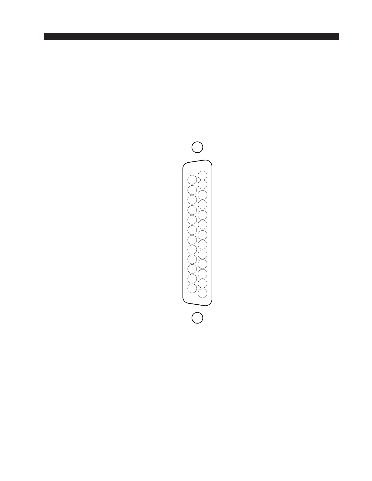
All user wiring to the SRC-8 card takes place at the female DB-25 I/O
connector on the cage rear.
DB-25—Digital Audio Connections
These include eight input sources. Pinout drawing on page 2-8 shows all
wiring connections at a glance.
Pin 24 – HI
Pin 12 – LO AES 1 In
Pin 25 – SH
Pin 10 – HI
Pin 23 – LO AES 2 In
Pin 11 – SH
Pin 21 – HI
Pin 9 – LO AES 3 In
Pin 22 – SH
Pin 7 – HI
Pin 20 – LO AES 4 In
Pin 8 – SH
Pin 18 – HI
Pin 6 – LO AES 5 In
Pin 19 – SH
Pin 4 – HI
Pin 17 – LO AES 6 In
Pin 5 – SH
Pin 15 – HI
Pin 3 – LO AES 7 In
Pin 16 – SH
Pin 1 – HI
Pin 14 – LO AES 8 In
Pin 2 – SH
ADR-32 / Dec 2002
page 2 – 7
Page 21
HARDWARE
SRC-8 Card
Digital Input Connections
I/O PORTS
(DB-25)
AES 1 IN SH
AES 1 IN HI
AES 2 IN LO
AES 3 IN SH
AES 3 IN HI
AES 4 IN LO
AES 5 IN SH
AES 5 IN HI
AES 6 IN LO
AES 7 IN SH
AES 7 IN HI
AES 8 IN LO
25
24
23
22
21
20
19
18
17
16
15
14
13
12
11
10
9
8
7
6
5
4
3
2
1
AUDIO GROUND
AES 1 IN LO
AES 2 IN SH
AES 2 IN HI
AES 3 IN LO
AES 4 IN SH
AES 4 IN HI
AES 5 IN LO
AES 6 IN SH
AES 6 IN HI
AES 7 IN LO
AES 8 IN SH
AES 8 IN HI
ADR-32 / Dec 2002
page 2 – 8
Page 22

HARDWARE
Analog Input Card (ADC-4)
Overview
The Analog input card accepts up to 4 stereo analog audio sources (i.e.
8 mono channels). A Signal Definitions form in the supplied X-Point
software allows the user to set attributes for the input channel hardware,
including signal name, type, circuit #, etc. The 8 input channels may be
configured as mono signals (one channel), stereo signals (two channels),
or 5.1 surround sound signals (six channels) in any combination. Signals
may span across input cards (e.g. a surround sound signal may have 4
channels on one input card, and 2 channels on a different input card).
The balanced, line level analog input signals are buffered and converted to the digital domain by 24bit A-D converters operating at the
system’s master sample rate. Embedded logic routes each channel of
audio data into an available time slot of the input card’s TDM bus. One
TDM bus is allocated for each input card.
Analog Input Interface
The balanced analog input stages are direct coupled, unity gain circuits
and operate at a nominal input level of +4dBu. The input impedance is
20kΩ. A +4dBu input signal will result in a -20dBFS digital output level
at any of the selected AES outputs. The maximum analog input signal
level is +24 dBu providing 20 dB of headroom above the nominal input
level.
Reference Notes:
0dBu = .7746 V RMS, +4dBu = 1.23V RMS
dBFS = dB Full Scale Digital
-20dBFS = +4dBu
Internal Programming Options
There are no internal programming options on the ADC-4 card.
ADR-32 / Dec 2002
page 2 – 9
Page 23
HARDWARE
Hook-Ups
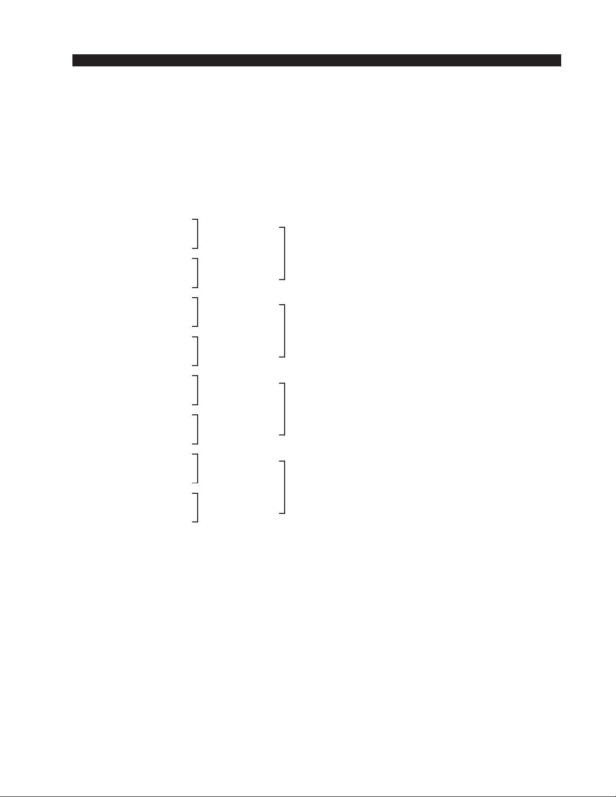
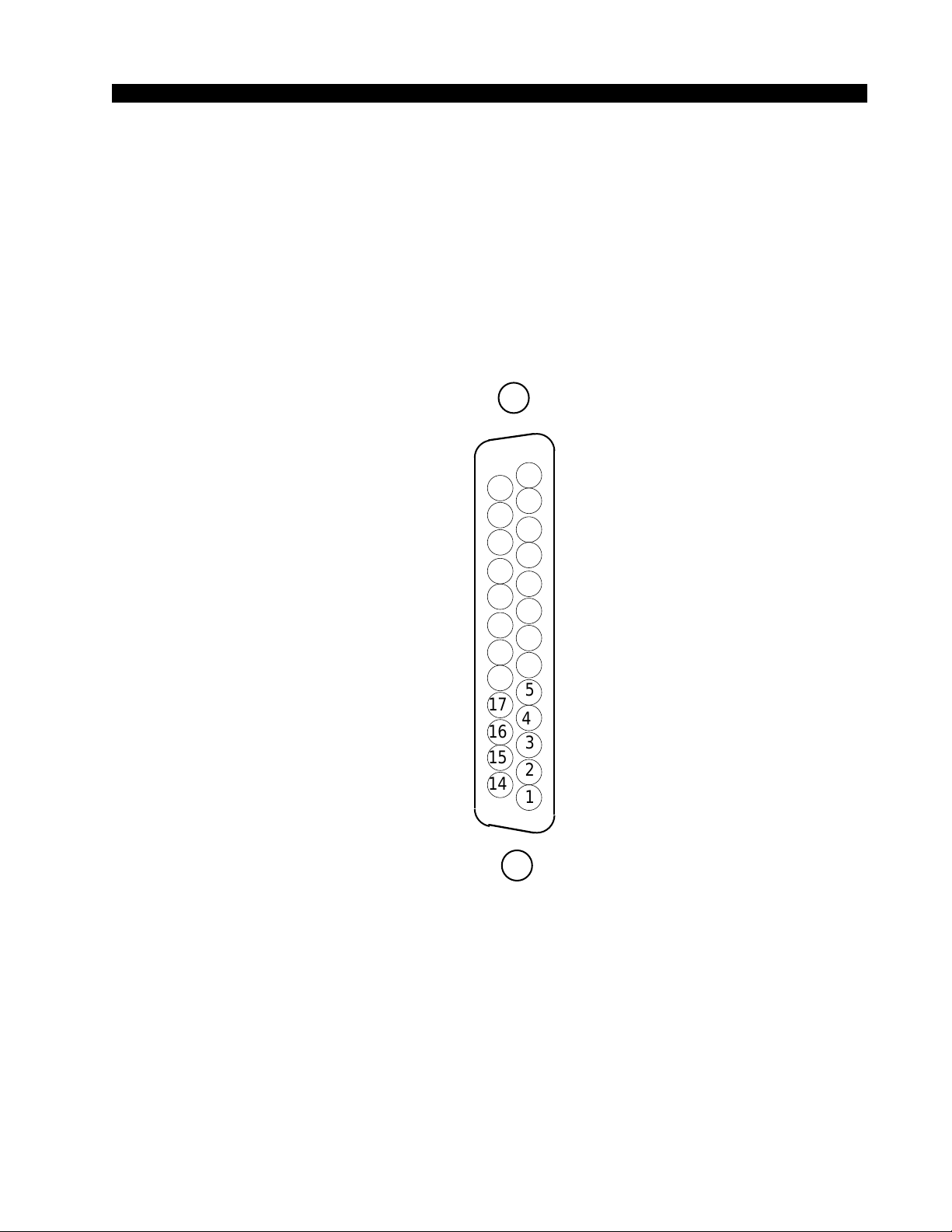
All user wiring to the ADC-4 card takes place at the female DB-25
connector on the cage rear.
DB-25—Analog Audio Connections
These include four (1-4) input sources. Pinout drawing on page 2-11 shows
all wiring connections at a glance.
Pin 24 – HI
Pin 12 – LO Channel 1 In LT
Pin 25 – SH
Pin 10 – HI
Pin 23 – LO Channel 2 In RT
Pin 11 – SH
Pin 21 – HI
Pin 9 – LO Channel 3 In LT
Pin 22 - SH
Pin 7 – HI
Pin 20 – LO Channel 4 In RT
Pin 8 – SH
Pin 18 – HI
Pin 6 – LO Channel 5 In LT
Pin 19 – SH
Pin 4 – HI
Pin 17 – LO Channel 6 In RT
Pin 5 – SH
Pin 15 – HI
Pin 3 – LO Channel 7 In LT
Pin 16 – SH
Pin 1 – HI
Pin 14 – LO Channel 8 In RT
Pin 2 – SH
Stereo 1 In
Stereo 2 In
Stereo 3 In
Stereo 4 In
Mono Inputs
The easiest way to connect mono analog sources is to strap the mono source
across both the left and right sides of a stereo input. Optionally, you may
reconfigure stereo inputs for 2 channel mono operation in software. Please see
“Signal Definition” section in the “X-Point Software Setup Guide”.
ADR-32 / Dec 2002
page 2 – 10
Page 24
HARDWARE
(
)
ADC-4
Analog Input Connections
I/O PORTS
DB-25
CHANNEL 1 (STEREO 1 LT) IN SH
CHANNEL 1 (STEREO 1 LT) IN HI
CHANNEL 2 (STEREO 1 RT) IN LO
CHANNEL 3 (STEREO 2 LT) IN SH
CHANNEL 3 (STEREO 2 LT) IN HI
CHANNEL 4 (STEREO 2 RT) IN LO
CHANNEL 5 (STEREO 3 LT) IN SH
CHANNEL 5 (STEREO 3 LT) IN HI
CHANNEL 6 (STEREO 3 RT) IN LO
CHANNEL 7 (STEREO 4 LT) IN SH
CHANNEL 7 (STEREO 4 LT) IN HI
CHANNEL 8 (STEREO 4 RT) IN LO
25
24
23
22
21
20
19
18
17
16
15
14
13
12
11
10
6
4
AUDIO GROUND
CHANNEL 1 (STEREO 1 LT) IN LO
CHANNEL 2 (STEREO 1 RT) IN SH
CHANNEL 2 (STEREO 1 RT) IN HI
CHANNEL 3 (STEREO 2 LT) IN LO
9
CHANNEL 4 (STEREO 2 RT) IN SH
8
CHANNEL 4 (STEREO 2 RT) IN HI
7
CHANNEL 5 (STEREO 3 LT) IN LO
CHANNEL 6 (STEREO 3 RT) IN SH
5
CHANNEL 6 (STEREO 3 RT) IN HI
CHANNEL 7 (STEREO 4 LT) IN LO
3
CHANNEL 8 (STEREO 4 RT) IN SH
2
CHANNEL 8 (STEREO 4 RT) IN HI
1
ADR-32 / Dec 2002
page 2 – 11
Page 25

HARDWARE
Digital Output Card (DO-8)
Overview
Each Digital Output card provides 8 physical AES-3 formatted outputs.
A Signal Definitions form in the supplied X-Point software allows the user
to set attributes for the output channels, including signal name, type, circuit
#, etc. The 8 AES outputs are configured in software at the factory to be stereo
output signals.
Each output card listens for connection commands from the CPU, and
then uses this information to connect the appropriate sources to their selected
output channels. The selected audio data is fed to AES transmitters which
format the 24 bit audio data according to the AES-3 standard.
Note: While it is possible to split the 8 stereo AES outputs into 16 mono
channels, there are still only 8 physical wires, each containing the 2-channel
AES formatted data.
AES Output Interface
The balanced digital audio outputs on the DO-8 card are transformer
coupled and exhibit a nominal output impedance of 110Ω. This interface
operates at a nominal output voltage of +5V p-p and conforms to the AES3 1992 electrical specification. The DO-8 output cards operate at unity gain
and transmit 24bit audio data word lengths at the system sample rate. Output
sample rate is set to 44.1 kHz or 48 kHz by setting the dipswitch located on
the PR-32 motherboard. Optionally, the CPU’s External AES Sync input
may be used to slave the system to a user provided 44.1 kHz or 48 kHz
reference rate. Please refer to the CPU hardware section for details on
external synchronization.
The digital output signal reference level is -20dBFS. A +4dBu analog
input signal yields a -20dBFS digital output signal. Channel Status implementation complies with rules for “Standard implementation” as described
in the AES-3 1992 specification.
ADR-32 / Dec 2002
page 2 – 12
Page 26

HARDWARE
AES Channel Status Implementation
The following embedded channel status information is transmitted at the
AES digital outputs along with the audio data.
Note: Channel Status bits are identically set for channels 1 and 2.
CHANNEL STATUS: PROFESSIONAL
DATA USE: AUDIO (normal mode)
EMPHASIS: NO EMPHASIS
SOURCE Fs LOCK: LOCKED
SAMPLE FREQUENCY: 44.1 kHz or 48 kHz*
CHANNEL MODE: STEREO
USER BITS MODE: NONE
AUX BITS USE: 24 BIT - main audio
AUDIO WORD LENGTH: 24 BIT
REFERENCE SIGNAL: NOT A REFERENCE SIGNAL
ORIGIN: NOT INDICATED
DESTINATION: NOT INDICATED
SAMPLE #: Ø
TIME OF DAY: ØØ : ØØ : ØØ
BLOCK CRC: IS VALID
* The Sample Rate frequency
reported in the channel status
block depends upon a dipswitch
setting on the PR-32 circuit
board. DipSW6 - pos.3: OFF =
48 kHz, ON = 44.1 kHz.
Internal Programming Options
There are no internal programming options on the DO-8 card.
Hook-Ups
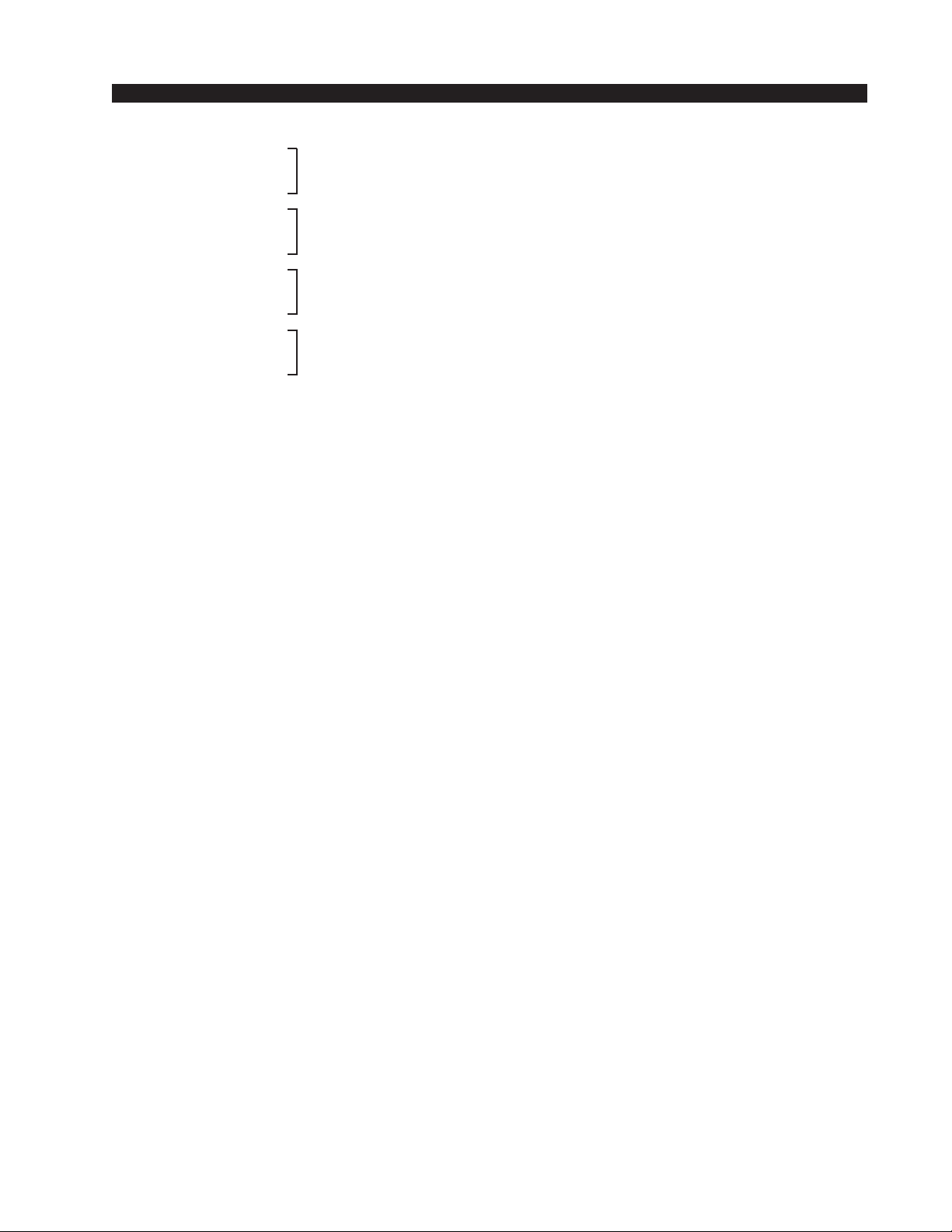
All user wiring from the DO-8 card takes place at the female DB-25
connector on the cage rear.
Digital Audio Connections
These include eight outputs. Pinout drawing on page 2-15 shows all
wiring connections at a glance.
Pin 24 – HI
Pin 12 – LO AES 1 Out
Pin 25 – SH
Pin 10 – HI
Pin 23 – LO AES 2 Out
Pin 11 – SH
Pin 21 – HI
Pin 9 – LO AES 3 Out
Pin 22 – SH
Pin 7 – HI
Pin 20 – LO AES 4 Out
Pin 8 – SH
ADR-32 / Dec 2002
page 2 – 13
Page 27
Pin 18 – HI
Pin 6 – LO AES 5 Out
Pin 19 – SH
Pin 4 – HI
Pin 17 – LO AES 6 Out
Pin 5 – SH
Pin 15 – HI
Pin 3 – LO AES 7 Out
Pin 16 – SH
Pin 1 – HI
Pin 14 – LO AES 8 Out
Pin 2 – SH
HARDWARE
ADR-32 / Dec 2002
page 2 – 14
Page 28
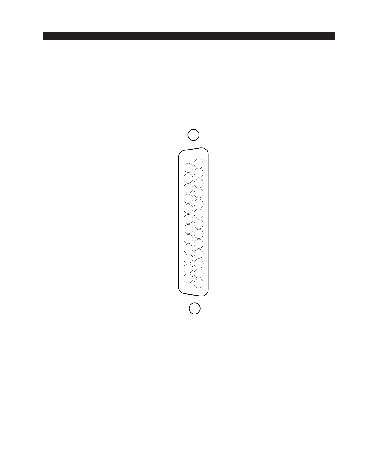
HARDWARE
(
)
DO-8
Digital Output Connections
I/O PORTS
DB-25
AES 1 OUT SH
AES 1 OUT HI
AES 2 OUT LO
AES 3 OUT SH
AES 3 OUT HI
AES 4 OUT LO
AES 5 OUT SH
AES 5 OUT HI
AES 6 OUT LO
AES 7 OUT SH
AES 7 OUT HI
AES 8 OUT LO
25
24
23
22
21
20
19
18
17
16
15
14
13
12
11
10
6
4
AUDIO GROUND
AES 1 OUT LO
AES 2 OUT SH
AES 2 OUT HI
AES 3 OUT LO
9
AES 4 OUT SH
8
AES 4 OUT HI
7
AES 5 OUT LO
AES 6 OUTSH
5
AES 6 OUT HI
AES 7 OUT LO
3
AES 8 OUT SH
2
AES 8 OUT HI
1
ADR-32 / Dec 2002
page 2 – 15
Page 29

Overview
HARDWARE
Analog Output Card (AO-4)
Each Analog Output card provides 8 physical monaural output channels.
These output channels are configured in software to be 4 stereo pairs.
A Signal Definitions form in the supplied X-Point software allows the user
to set attributes for the output channels, including signal name, type,
circuit #, etc.
Each output card listens for connection commands from the CPU and
then uses this information to connect the appropriate sources to their selected
output channels. The selected audio data is fed to 24 bit, two-channel digitalto-analog converters. The D-A converter outputs are buffered by integrated
differential output drivers.
Analog Output Interface
Each balanced unity gain output will drive loads up to 600Ω and behaves
much like a transformer in that either side of the balanced output may be
grounded. The analog outputs are direct coupled with an output impedance
of 50Ω and a nominal output signal level of +4dBu for an analog input signal
of +4dBu (-20dBFs digital) .
Internal Programming Options
There are no internal programming options on the AO-4 card.
ADR-32 / Dec 2002
page 2 – 16
Page 30
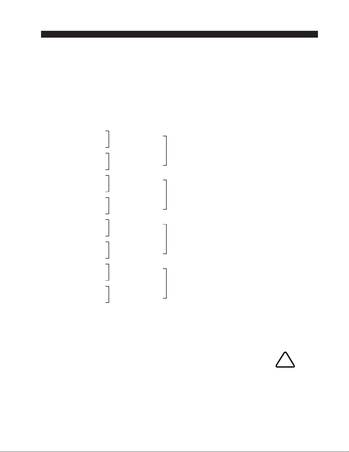
HARDWARE
Hook-Ups
All user wiring from the AO-4 card takes place at the female DB-25
connector on the cage rear.
Analog Audio Connections
These include four (1-4) outputs. Pinout drawing on page 2-19 shows
all wiring connections at a glance.
Pin 24 – HI
Pin 12 – LO Channel 1 Out LT
Pin 25 – SH
Pin 10 – HI
Pin 23 – LO Channel 2 Out RT
Pin 11 – SH
Pin 21 – HI
Pin 9 – LO Channel 3 Out LT
Pin 22 - SH
Pin 7 – HI
Pin 20 – LO Channel 4 Out RT
Pin 8 – SH
Pin 18 – HI
Pin 6 – LO Channel 5 Out LT
Pin 19 – SH
Pin 4 – HI
Pin 17 – LO Channel 6 Out RT
Pin 5 – SH
Pin 15 – HI
Pin 3 – LO Channel 7 Out LT
Pin 16 – SH
Pin 1 – HI
Pin 14 – LO Channel 8 Out RT
Pin 2 – SH
Stereo 1 Out
Stereo 2 Out
Stereo 3 Out
Stereo 4 Out
Mono Outputs
There are two ways to adapt the ADR-32 for mono operation.
Externally sum a stereo output using 1kΩ resistors, or reconfigure the
output in software for mono operation. Please see the “X-Point Software
Setup Guide” for details on configuring mono outputs.
Caution! If you route a stereo input to a software configured mono
output, only one output channel will be present.
ADR-32 / Dec 2002
!
page 2 – 17
Page 31
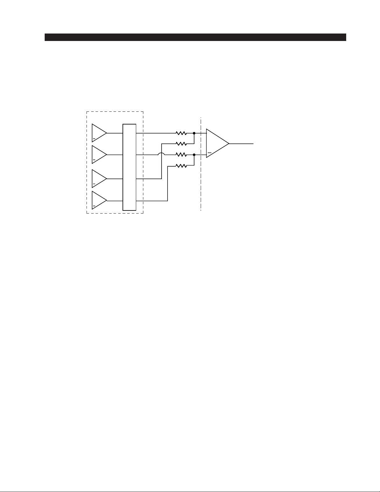
HARDWARE
External Mono Summing
To sum an ADR-32 stereo analog output add a 1kΩ resistor in series
with each leg of the balanced output. Add resistors as close as possible
to the mono input.
Example:
ADR-32
AO-4 OUTPUT
+
LT+
+
LT-
+
RT+
+
RT-
DB-25
LT+
RT+
LT-
RT-
1K
1K
1K
1K
EXTERNAL DEVICE
MONO INPUT
+
ADR-32 / Dec 2002
page 2 – 18
Page 32
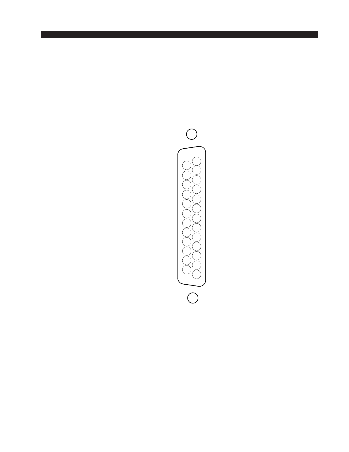
HARDWARE
(
)
AO-4
Analog Output Connections
I/O PORTS
DB-25
CHANNEL 1 (STEREO 1 LT) OUT SH
CHANNEL 1 (STEREO 1 LT) OUT HI
CHANNEL 2 (STEREO 1 RT) OUT LO
CHANNEL 3 (STEREO 2 LT) OUT SH
CHANNEL 3 (STEREO 2 LT) OUT HI
CHANNEL 4 (STEREO 2 RT) OUTLO
CHANNEL 5 (STEREO 3 LT) OUT SH
CHANNEL 5 (STEREO 3 LT) OUT HI
CHANNEL 6 (STEREO 3 RT) OUT LO
CHANNEL 7 (STEREO 4 LT) OUT SH
CHANNEL 7 (STEREO 4 LT) OUT HI
CHANNEL 8 (STEREO 4 RT) OUT LO
25
24
23
22
21
20
19
18
17
16
15
14
13
12
11
10
9
8
7
6
5
4
3
2
1
AUDIO GROUND
CHANNEL 1 (STEREO 1 LT) OUT LO
CHANNEL 2 (STEREO 1 RT) OUT SH
CHANNEL 2 (STEREO 1 RT) OUT HI
CHANNEL 3 (STEREO 2 LT) OUT LO
CHANNEL 4 (STEREO 2 RT) OUT SH
CHANNEL 4 (STEREO 2 RT) OUT HI
CHANNEL 5 (STEREO 3 LT) OUT LO
CHANNEL 6 (STEREO 3 RT) OUT SH
CHANNEL 6 (STEREO 3 RT) OUT HI
CHANNEL 7 (STEREO 4 LT) OUT LO
CHANNEL 8 (STEREO 4 RT) OUT SH
CHANNEL 8 (STEREO 4 RT) OUT HI
ADR-32 / Dec 2002
page 2 – 19
Page 33

HARDWARE
Monitor Output & Speaker Mute
Overview
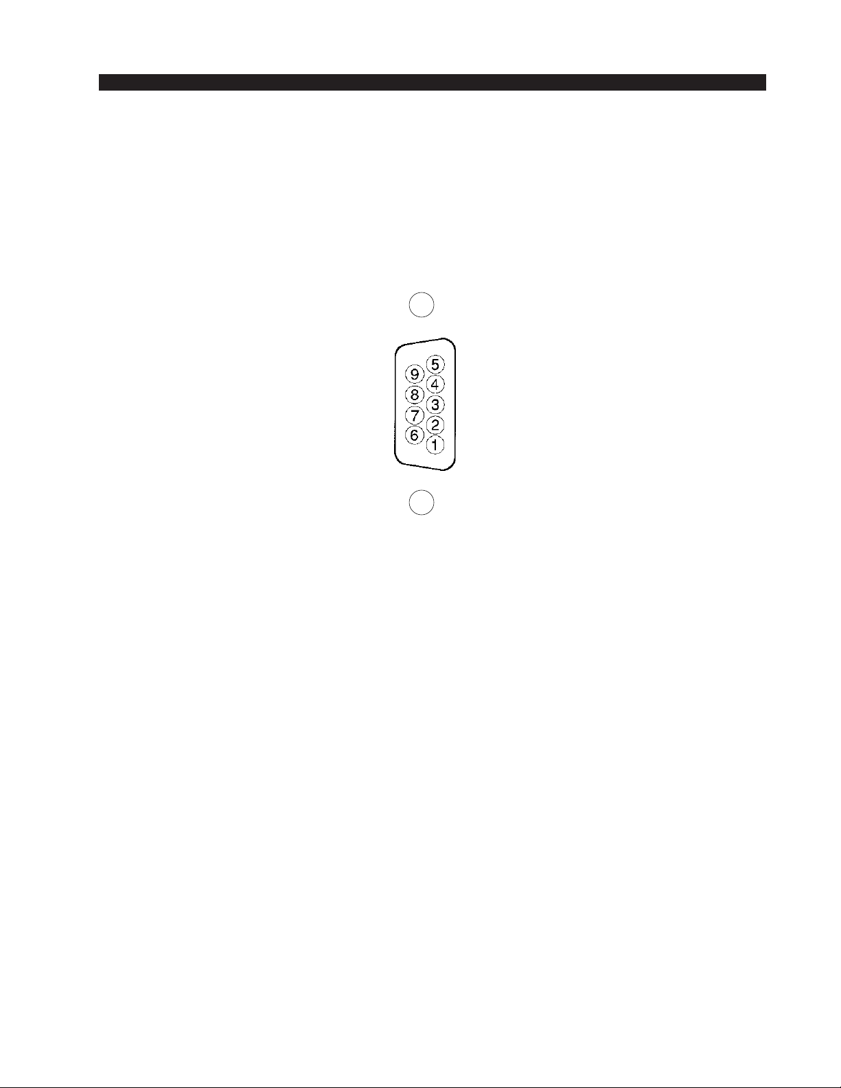
The monitor output port provides a way to remotely monitor any source
routed to the ADR-32’s internal speaker destination. The mono monitor
output is electronically balanced, and operates at line level.
A speaker mute function is included for applications where the ADR-32
is mounted in an ON-AIR or Production control room. A contact closure
across pins 1 and 6 will mute the ADR-32’s internal speaker.
Hook-Ups
All user monitor wiring takes place at the female DB-9 connector on the
cage rear.
Pin 4 – Monitor Out HI
Pin 9 – Monitor Out LO
Pin 5 – Monitor Out SH
Pin 7 – N/C
Pin 8 – SH
Pin 3 – N/C
Pin 1 – SPKR MUTE
Pin 6 – GND
Pin 2 – SH
ADR-32 / Dec 2002
page 2 – 20
Page 34
HARDWARE
Monitor Connections
PORTS
(DB-9)
MONITOR LO
SH
N/C
GND
MONITOR SH
MONITOR HI
N/C
SH
SPKR MUTE
ADR-32 / Dec 2002
page 2 – 21
Page 35

HARDWARE
CPU
Overview
The CPU used in the ADR-32 incorporates a PC/104 computer mounted
on the PR-32 PCB. The host computer utilizes RAM, a flash disk (which
emulates a standard IDE hard drive) and an Ethernet port. There is no hard
disk drive. Keyboard, floppy controller and video ports are for factory use
only.
The purpose of the CPU is to provide control of the ADR-32 system. The
CPU communicates to the X-Point Configuration PC and XY Controller
GUI’s via TCP/IP over Ethernet, via a backplane command bus to the other
cards, and via RS-485 serial links to existing XY Controllers and Wheatstone
consoles. The CPU also phase locks the ADR-32 to an onboard crystal
oscillator or an external AES “black” reference source.
Hardware and software configuration as well as real time crosspoint
information is saved in non-volatile storage on the CPU and is restored at
power up or reset. This configuration information provides details to the
application running on the CPU such as the specific audio hardware available, serial port allocation, I/O signal names, etc., and may be modified via
the Configuration GUI. Switching information is dynamically controlled via
both hardware based XY Controllers and PC based XY GUI’s. Network IP
address configuration of the CPU is handled by the provided DOS utility
application. System configuration is discussed in detail in the following
sections.
CPU BIOS Settings/Format
BIOS Setup and formatting of the ADR-32's CPU is completed prior to
the testing of your ADR-32 Router at the Wheatstone factory. There are no
user adjustable settings. Please contact customer support with questions
regarding the PC/104 SBC BIOS settings or flash disk formatting.
Ethernet IP Addressing
Wheatstone ADR-32 digital audio routers ship with the CPU IP address
set for 192.168.1.160. Peer to peer connections between a PC and the
ADR-32 only require you to set the PC IP address to live on the same subnet
as the ADR-32.
Before the switch will be recognized on your network, you will most
likely need to re-configure the ADR-32's CPU and X-Point PC’s IP addresses. To change the ADR-32's CPU IP address, a network utility application, supplied on the X-Point CD-ROM, must be run. See the IP Address
Quick Start section of the “X-Point Software Setup Guide” for detailed
information.
ADR-32 / Dec 2002
page 2 – 22
Page 36
HARDWARE
Ethernet Interface Wiring
Stand-alone systems are defined as the ADR-32 connected to an X-Point
configuration PC and not interfaced to a station’s existing network. Standalone systems are “point to point” configurations and are connected by a
CAT-5 crossover cable.
Networked systems are defined as the ADR-32 connected directly to an
existing Ethernet network hub. Networked systems are connected to the
network hub via a straight (pin to pin) CAT-5 cable. Typical CAT-5 cable
pinouts are included in the “Hook-Ups” section near the end of this chapter.
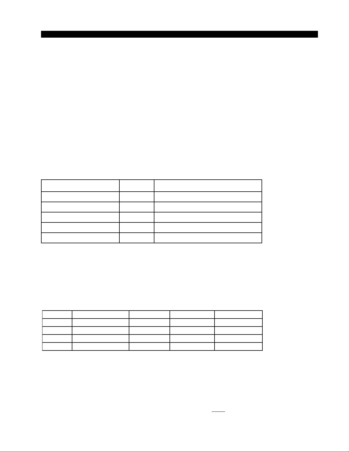
Internal Programming Options
All internal programming options are made via PCB mounted dipswitches
and jumpers as shown in the table below:
CPU (PR-32 PCB)
NAME REF.DES. DEFAULT
48H_44.1L
SW6 pos1
ON-48 kHz
AUTODETECT SW6 pos2 ON
485_CONSOLE_TERM
485_XYC_TERM
SW1, SW2
SW3, SW4
BIAS TERMINATION
BIAS TERMINATION
XYC_ADDRESS J3-J10 DEFAULT ID=32, J5-INSTALLED
Switch Settings
DIPSW1-SW4 RS-485 Termination
These four, 4-position dipswitches configure the 485 port termination as
follows:
SW1-SW4
POSITION BIASED TERM PASSIVE TERM UNTERMINATED
1 - TX10Ω
2 - TX+
3 - TX4 - 120Ω
Choices are Unterminated, Normal (Passive) Termination, or BIAS Termination on the transmit and receive lines. SW1 and SW2 are for Port A, and
SW3 and SW4 are for Port B. SW1 and SW3 are for the RS-485 transmitter’s
termination on the CPU; SW2 and SW4 are for receiver terminations.
An RS-485 bus may only be BIAS TERMINATED at one end. All
peripheral devices are set for NO TERMINATION by default. Set the
TERMINATION to ON for the last controller or console only, in an RS-485
chain.
FUNCTION
ON=10Ω BYPASS
ON=750Ω PULLUP
ON=750Ω PULLDOWN
ON=120Ω PARALLEL
OFF*
ON*
ON*
ON*
ON
OFF
OFF
ON
OFF
OFF
OFF
OFF
ADR-32 / Dec 2002
page 2 – 23
Page 37
HARDWARE
DIPSW6
Pos.1 - 48/44.1 Select - sets the AES out sample rate, ON = 48 kHz, OFF =
44.1 kHz
Pos.2 - Autodetect - default is “ON”
Autodetect will sense the presence of an external AES input clock and
slave the system to this AES reference. If the AES reference fails (wire breaks,
etc.) the system will revert to the onboard crystal reference until the external
AES input returns. If autodetect is disabled the system ignore the external AES
reference and always use the onboard crystal.
Pos.3 - DIP SW 2 - not used
Pos.4 - DIP SW 3 - not used
Jumper Settings
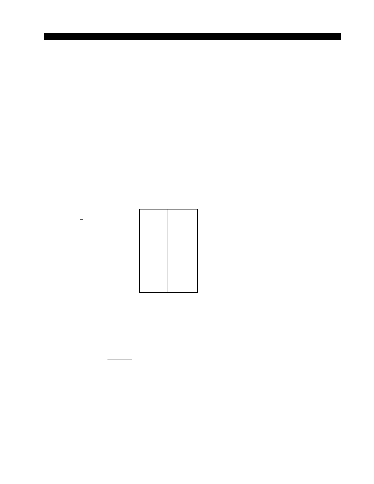
Jumpers J3-J10 - Determine XY Controller ID#
Bit Weight
Jumper J10 0 1
Jumper J9 1 2
Jumper J8 2 4
Jumper J7 3 8
XYC
Jumper J6 4 16
ID
Jumper J5 5 32
Jumper J4 6 64
Jumper J3 7 128
Note: Each ADR-32 XY Controller ID# is set using jumpers J3-J10. These
jumpers are read as an 8 bit field with Bit Ø mapped to J10 and Bit 7 mapped
to J3. This ID# is read by the CPU at boot up and is required by the ADR-32
serial communications software.
Example: Desired ID=17, shunt J6 and J10.
If there is more than one XY Controller connected to the ADR-32 router,
each XY Controller MUST have a unique ID#. The default XY Controller ID
is 32 (Jumper J5-shunted).
J11 - Watchdog timer pushbutton reset - factory use only
J12 - FPGA PGM - factory use only
ADR-32 / Dec 2002
page 2 – 24
Page 38

HARDWARE
Serial Interface Ports
Serial ports XYC and CONSOLE are typically used to connect remotely
located XY Controllers and Wheatstone Consoles to the switch via 4-wire
RS-485. These ports are configured from the X-Point GUI and are setup at the
factory as follows:
Port A - CONSOLE PORT - RS-485, 9600 bps, Console port
Port B - XYC PORT - RS-485, 38400 bps, XY controller port
Hook-Ups
All user wiring to and from CPU takes place at two DB-9 female serial
interface connectors, and one RJ-45 Ethernet connector on the cage rear.
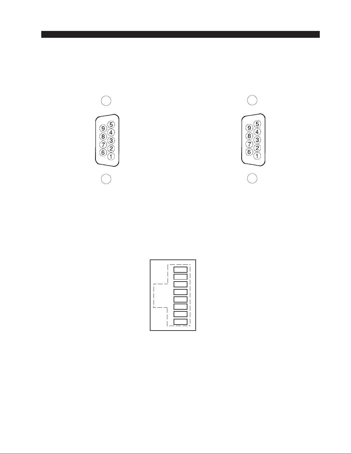
Pinout drawing on page 2-27 shows all wiring connections at a glance.
“CONSOLE I/O” DB-9—S
PIN 5 – AES SYNC OUT SH
P
IN
4 – AES SYNC OUT HI
P
IN
9 – AES SYNC OUT LO
P
IN
3 – RX1 HI (RS-485)
P
IN
8 – RX1 LO (RS-485)
P
IN
2 – TX (RS-232)
P
IN
7 – RX (RS-232)
P
IN
1 – TX1 HI (RS-485)
P
IN
6 – TX1 LO (RS-485)
“XYC I/O” DB-9—S
PIN 5 – AES SYNC IN SH
P
IN
4 – AES SYNC IN HI
P
IN
9 – AES SYNC IN LO
P
IN
3 – RX2 HI (RS-485)
P
IN
8 – RX2 LO (RS-485)
P
IN
2 – N/C
P
IN
7 – N/C
P
IN
1 – TX2 HI (RS-485)
P
IN
6 – TX2 LO (RS-485)
ERIAL INTERFACE
ERIAL INTERFACE
P
ORT CONNECTIONS
P
ORT CONNECTIONS
RJ-45—E
PIN 1 – TXD +
P
IN
P
IN
P
IN
P
IN
P
IN
P
IN
P
IN
ADR-32 / Dec 2002
THERNET
2 – TXD 3 – RXD +
4 – N/C
5 – N/C
6 – RXD -
7 – N/C
8 – N/C
C
ONNECTIONS
page 2 – 25
Page 39

HARDWARE
CN/C
CN/C
C
C
C
C
C
C
C
C
T
White/Orange
Orange
RJ-45
Plug
White/Green
Blue
White/Blue
Green
White/Brown
Brown
U
SED FOR CONNECTING THE
T
PIN
1
2
3
4
5
6
7
8
YPICAL
CPU TO
YPICAL
E
THERNET
TXD +
TXD RXD +
N/
RXD N/
YOUR NETWORK HUB
C
ROSSOVER
C
ABLE
C
PIN
White/Orange
1
Orange
2
White/Green
3
Blue
4
White/Blue
5
Green
6
White/Brown
7
Brown
8
.
ABLE
RJ-45
Plug
PIN
White/Orange
Orange
RJ-45
Plug
White/Green
Blue
White/Blue
Green
White/Brown
Brown
U
SED FOR SIMPLE “POINT TO POINT” CONNECTIONS BETWEEN THE SUPPLIED
C
ONFIGURATION
PC’S NIC
TXD +
1
TXD -
2
RXD +
3
N/
4
N/
5
RXD -
6
N/
7
N/
8
CARD AND THE
CPU.
RXD +
RXD -
TXD +
N/
N/
TXD N/
N/
PIN
1
2
3
4
5
6
7
8
White/Green
Green
White/Orange
Blue
White/Blue
Orange
White/Brown
Brown
RJ-45
Plug
XP
ADR-32 / Dec 2002
ADR-32 / Nov 02
page 2 – 26
Page 40
HARDWARE
O
H
Console Connections
AES SYNC OUT LO
RX1 LO (RS-485)
RX (RS-232)
TX1 LO (RS-485)
XYC Connections
I/O PORTS
(DB-9)
AES SYNC OUT SH
AES SYNC OUT HI
RX1 HI (RS-485)
TX (RS-232)
TX1 HI (RS-485)
AES SYNC IN L
RX2 LO (RS-485)
N/C
TX2 LO (RS-485)
Ethernet Connections
I/O PORTS
(DB-9)
AES SYNC IN S
AES SYNC IN HI
RX2 HI (RS-485)
N/C
TX2 HI (RS-485)
(RJ-45)
1
2
3
4
5
6
7
8
TXD +
TXD RXD +
N/C
N/C
RXD N/C
N/C
ADR-32 / Dec 2002
ADR-32 / Nov 02
page 2 – 27
Page 41

CONTROLLER DEVICES
Controller Devices
Chapter Contents
XP Configuration GUI ................................................................ 3-2
XY Controller GUI....................................................................... 3-3
XY Rack Controller..................................................................... 3-3
Console XY Controller ............................................................... 3-4
XY Controller Settings ............................................................... 3-4
Setting an XY Controller Termination..................................................................... 3-4
Setting an XY Controller Address........................................................................... 3-4
XY Controller Signal Visibility................................................... 3-5
XY Controller RS-485 Connections .......................................... 3-5
Overview ................................................................................................................. 3-5
Serial Port Note ...................................................................................................... 3-6
Cable Wiring ........................................................................................................... 3-6
Typical RS-485 Cable Specifications ....................................... 3-6
XY Controller RS-485 Cable Pinouts ........................................ 3-7
Wheatstone Console Interface.................................................. 3-8
Wheatstone Console RS-485 Connections.............................. 3-8
Console RS-485 Cable Pinouts................................................. 3-8
Console CPU Module Settings.................................................. 3-9
Console Address .................................................................................................... 3-9
RS-485 Select / Termination .................................................................................. 3-9
ADR-32 / Dec 2002
page 3 – 1
Page 42
CONTROLLER DEVICES
Controller Devices
The ADR-32 audio router has provisions for two levels of software
control and also two dedicated hardware controllers.
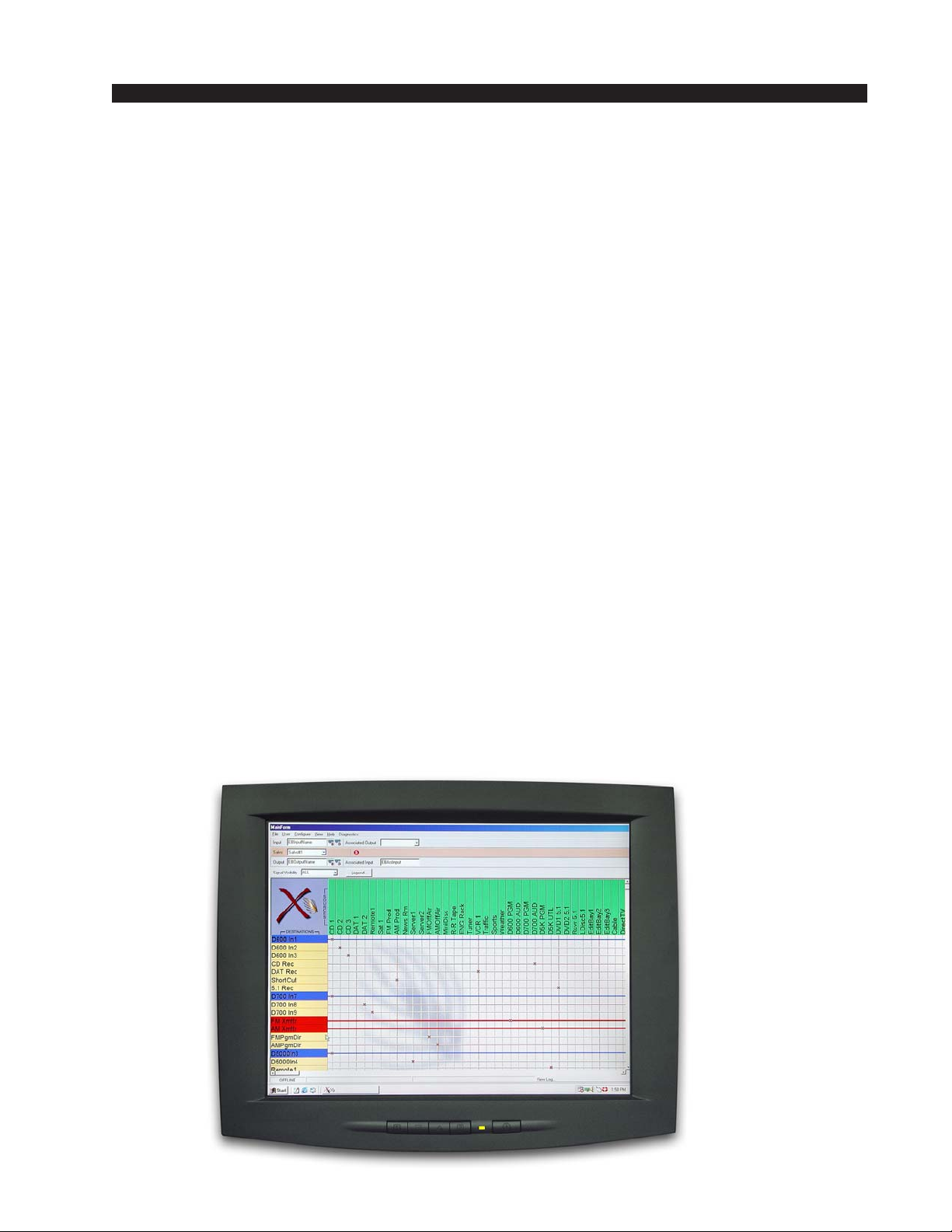
Software configuration and control of the system is handled by the
X-Point Configuration GUI described below. The X-Point Configuration
GUI may also be installed on multiple networked PC’s in a “controller only
mode”. This XY Controller GUI eliminates the need for new wiring and
hardware in certain locations and provides multi-user access to “mapped”
system resources.
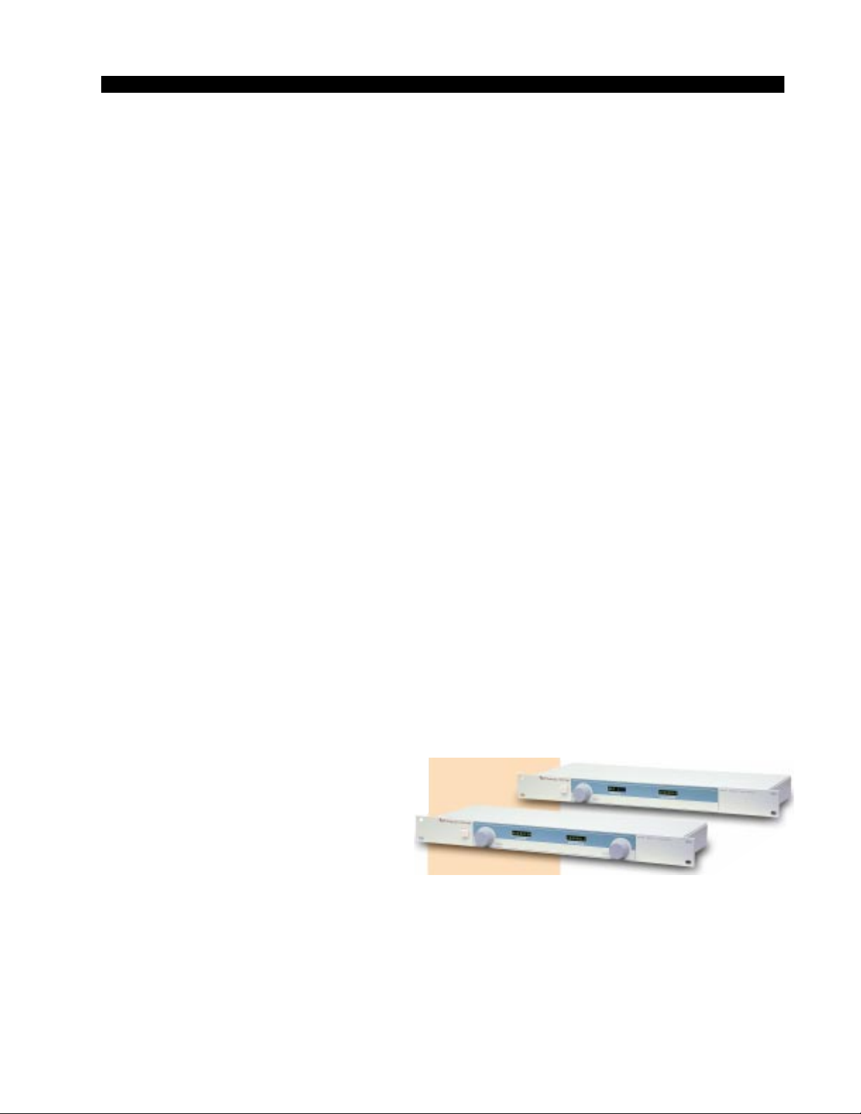
Two dedicated hardware controllers are also available. The single space
XY Rack controller provides a simple user interface and may be rack
mounted in a studio, talent location, edit booth, etc. A smaller console
mounted version of this controller is designed for installation in Wheatstone
consoles.
XP Configuration GUI
The supplied Windows™ application, X-Point, is a password protected
graphical user interface (GUI) which allows the user to configure, monitor
and control the ADR-32 digital audio router. The XP GUI communicates
using TCP/IP over Ethernet to the CPU. Once the system is configured the
XP program does not have to be continuously running.
The primary function of the X-Point GUI, running in administration
mode, is to provide the engineer or administrator with a means to define the
configuration of the hardware installed in the system. Configuration menus
allow the engineer access to hardware definitions for audio I/O cards, XY
rack controllers, serial port use, I/O signal names, etc. The administrator also
Please see the “X-Point
Software Setup Guide”
(Chapter 4) for detailed
software information.
ADR-32 / Dec 2002
page 3 – 2
Page 43
CONTROLLER DEVICES
has control over programmable features such as Salvo creation, crosspoint
locking, and mapping signal visibility to XY controllers. Further, certain
levels of system diagnostics may be accessed.
The XP GUI also provides a birds eye view of the current connection
status of the entire network router via a crosspoint grid display of the available
sources (inputs) and destinations (outputs). This GUI is also used to associate
human readable names with each of the signal sources and destinations.
XY Controller GUI
The X-Point application running in XY Controller mode is also known as
a “Crosspoint GUI”. Like the Configuration GUI, this device communicates
to the ADR-32 over Ethernet. However, it uses a UDP broadcast interface,
which allows multiple XYC GUI’s to communicate to the switch simultaneously. The number of XYC GUI’s that can run simultaneously is only
limited by the LAN configuration (theoretically millions could exist on the
same LAN, but 250 is a more practical limit).
Its main purpose is to provide an alternative, software based method of
controlling the ADR-32 utilizing a station’s existing network infrastructure.
Multiple, simultaneous users may connect signal sources to destinations and
monitor the status of audio resources throughout a facility. A signal visibility
feature allows users to only “see” the resources on the router that pertain to
their activities.
XY Rack Controller
The XY Rack Controller is a single rack unit device that can control the
connection of two signals. The operator dials in a Source (input signal) and
a Destination (output signal), then presses a TAKE button to connect or
disconnect (disconnect is accomplished by connecting to the source name that
designated a no connect for your system, such as “NO CONN”). Once
communications have been established the CPU or OAN card then directs the
selected devices to connect or disconnect
(if possible), and updates the crosspoint
state presented to the Configuration GUI,
XYC GUI, and other hardware XY Controllers.
Additionally, the operator may dial in
a SALVO, which automatically makes a
pre-configured number of connections.
A SALVO is somewhat analogous to a
“macro” in that several crosspoints are automatically effected from a single
user action.
This device communicates serially with the CPU via an RS-485 interface
bus. Up to 32 hardware based XY controllers may be daisy chained together
within a single cable run. Up to 32 hardware based XY controllers may be
installed in a system. On power up, the unit momentarily displays both the
firmware revision number and its address.
?
ADR-32 / Dec 2002
page 3 – 3
Page 44
CONTROLLER DEVICES
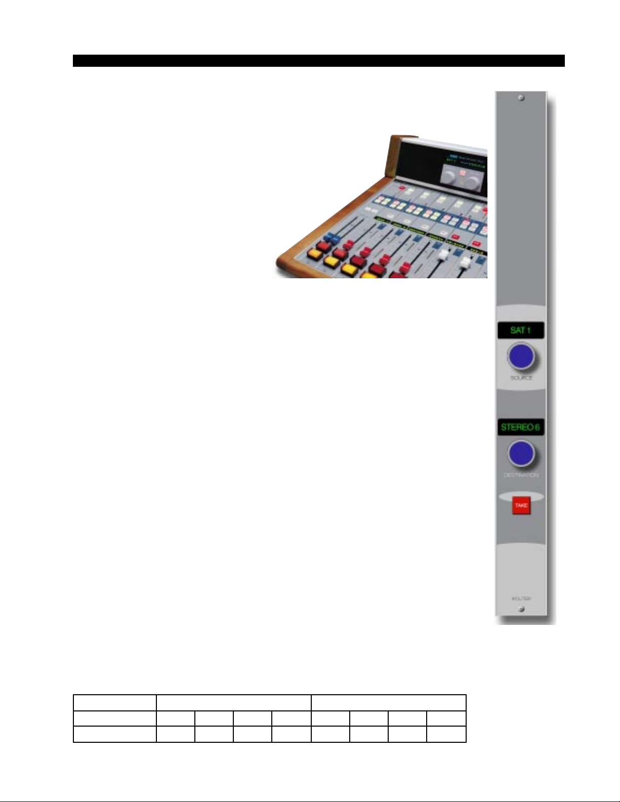
Console XY Controller
Identical in function to the XY
Rack Controller, the console XY
controller is packaged to mount in a
console meterbridge or, as a module, in the console mainframe. This
provides an integrated way of switching router sources to destinations
connected to the console. It is important to note that when mounted in
a console, the XY controller is really
an independent sub-system which
receives only power from the
console’s mainframe. The console
mounted “XYC” RS-485 DB-9’s (for meterbridge mounted controller and
D-70 XY module) or DB-25’s (for XY-4/8 and ALM-12d, D-16 XY
modules) connect to the XY controller electronics only.
XY Controller Settings
Setting an XY Controller Termination
Termination should be active only on the last controller in a chain.
XY Rack - install jumpers J1 and J2 on the XYR-1 pc board.
XY Meterbridge Mounted - install jumpers J2 and J3 on the XYC-600 pc
board.
XY-4/8 Module - turn on positions 2, 3, and 4 of dipswitch SW3 (pos1 not used) located on the XYC-700 pc board.
XYC Panel (D-70, ALM-12d, D-16 consoles) - install jumpers J3 and J4
on the XYC-70 pc board.
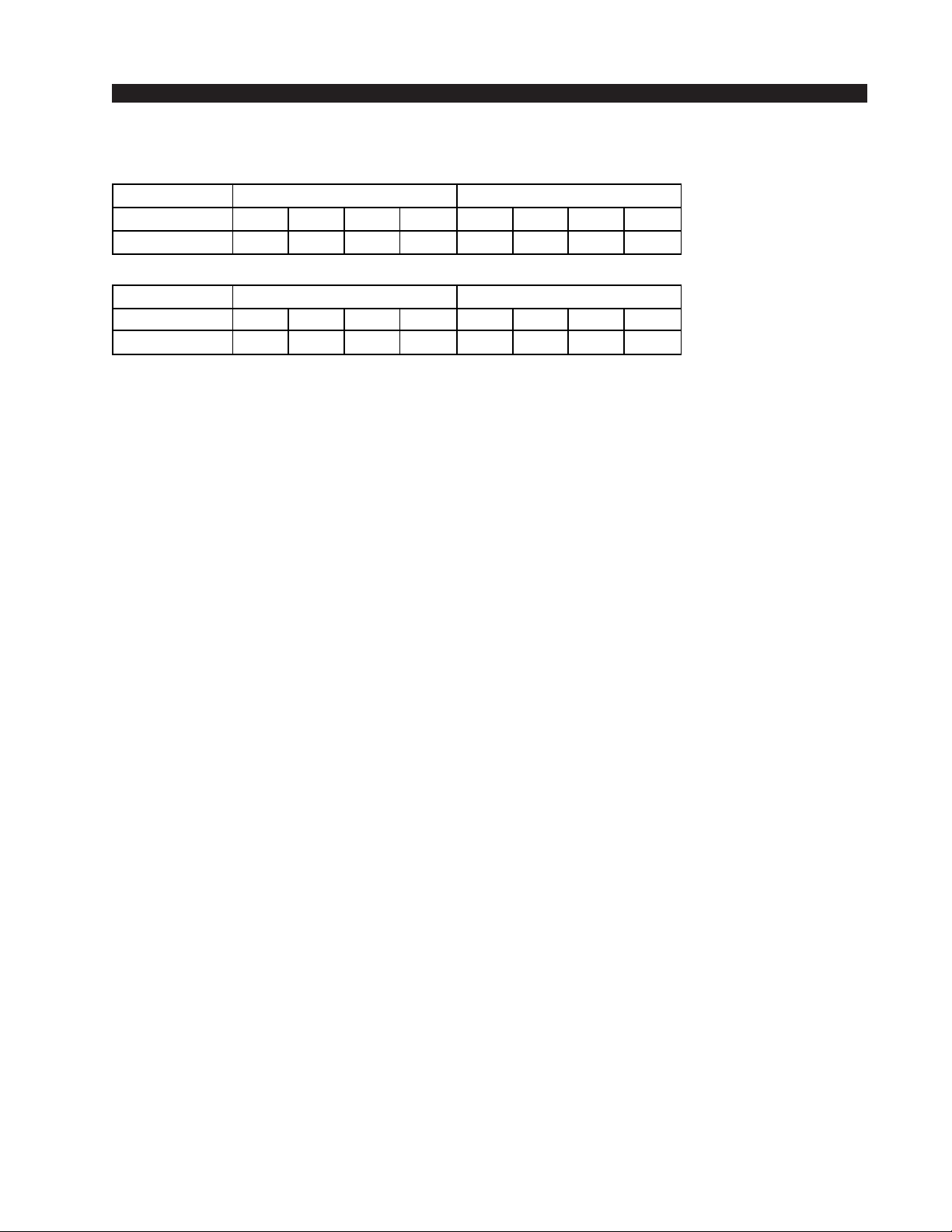
Setting an XY Controller Address
All hardware XY controllers have a unique address from 1 to 63 that
identifies their presence to the system. This address is set via a pair of four
position dipswitches mounted on the controller’s printed circuit card. XY
controller addresses are binary coded with each dipswitch carrying a specific
numerical weight ( e.g. 1, 2, 4, 8, 16, 32). To set an address, simply turn ON
the address dip switches until the total weights add up to the desired decimal
address. You can verify the address setting by powering up the XY controller
and watching for the address number in the controller’s displays. Addressing
is set at the factory and generally will not need to be changed in the field.
Below are the tables of switch positions and their weights.
XY RACK/XYC PANEL (D-70, ALM-12d & D-16)
DIPSWITCH #
POSITION
WEIGHT
ADR-32 / Dec 2002
ADR-32 / May 2003
SW3SW4
43214321
N/AN/A32168421
page 3 – 4
Page 45
CONTROLLER DEVICES
XYD-600 METERBRIDGE-MOUNTED CONTROLLER
DIPSWITCH #
POSITION
WEIGHT
XY-4/8 MODULE
DIPSWITCH #
POSITION
WEIGHT
SW1SW2
43214321
N/AN/A32168421
SW2SW1
43214321
N/AN/A32168421
XY Controller Signal Visibility
Once addressed, the XY controllers have the ability to “see” any or all of
the sources, destinations and Salvos available to the system. This function is
called signal visibility and is setup through the X-Point Configuration GUI.
Please refer to the X-Point software documentation for details on mapping
resources to specific XY Controllers.
XY Controller RS-485 Connections
Overview
The XY Rack and console mount controllers communicate with the
ADR-32 router via an RS-485 serial interface bus. The cable should be a low
capacitance computer communications cable.
Depending on the type of XY Controller, there are two type of cables:
• for XY Rack Controller, meterbridge mounted XY Controller and
XYC-70 Panel cables, terminated with DB-9 male connectors on both ends;
• for XY-4/8 console mounted module the ADR-32’s end of the cable is
terminated with a DB-9 male connector, and the console’s end of the cable is
terminated with a DB-25 male connector.
Typically, one end of the cable plugs into the XYC Serial Port DB-9
female connector on the cage rear, and the second end connects to either one
of the two DB-9 female I/O connectors on the rear of the XY Rack Controller
or bottom of the console meterbridge (for console mounted XY controllers),
or DB-25 female I/O connectors, mounted directly beneath XY-4/8 module
on the console mainframe’s bottom pan.
If there is more than one XY Controller, another cable goes between the
second I/O DB-9 connector on XY Controller #1 and the first DB-9 I/O
connector on the XY Controller #2, and so on (see diagram below). Up to 32
XY Rack or XY Console controllers may be daisy chained in this fashion on
a single cable run. Up to 32 XY controllers may be present in a system. Since
the ADR-32 contains its own XY Controller, only 31 additional XY Controllers can be connected to it.
ADR-32 / Dec 2002
page 3 – 5
Page 46
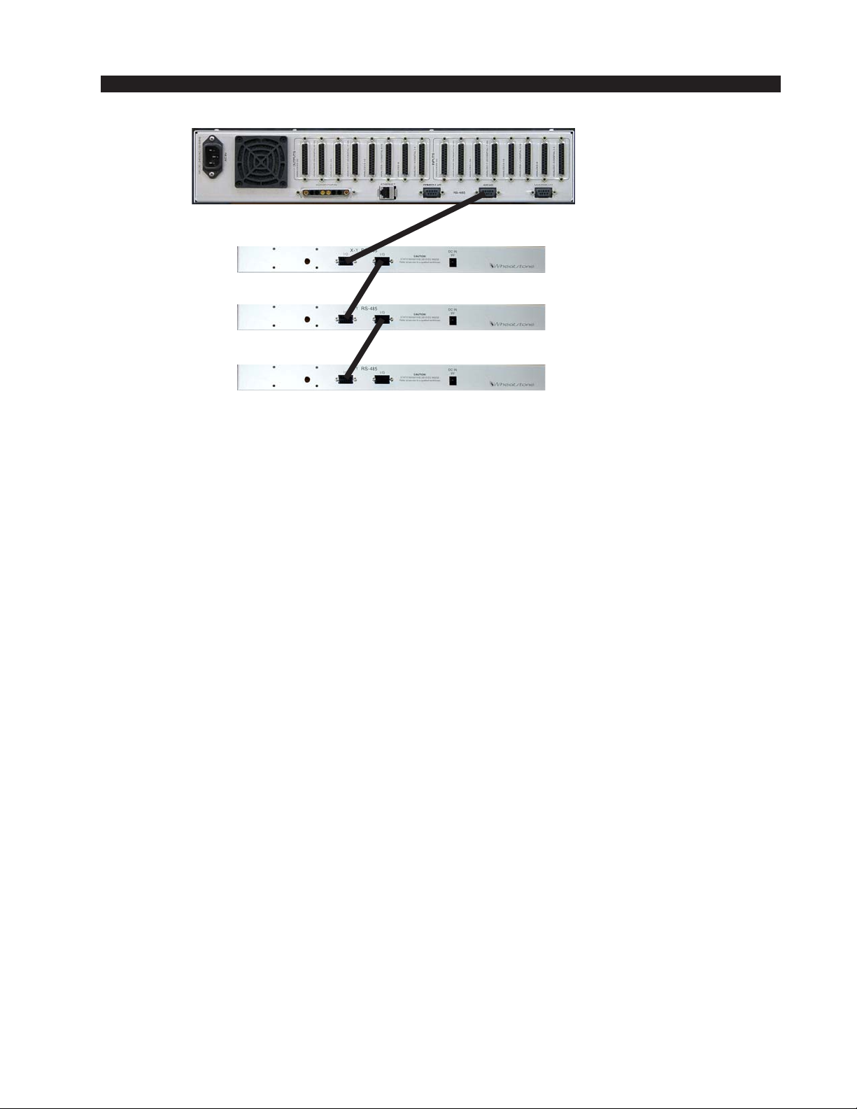
CONTROLLER DEVICES
ADR-32 REAR
XY CONTROLLER REAR
Connections Diagram
Serial Port Note
All XY controllers MUST be connected to the XYC I/O serial port. All
Wheatstone consoles MUST be connected to the CONSOLE I/O serial port.
Cable Wiring
It is important to use a high quality dual twisted pair cable suitable for
extended distance data transmission for the XY Controller RS-485 ports. A
cable with an impedance of 125 ohms and nominal capacitance of 12.8 pF/ft
@1 MHz is recommended. See cable specifications and pinouts for details.
Typical RS-485 Cable Specifications
Conductors 4 conductor plus shield (2 twisted pairs)
Conductor Gauge 24 AWG (7 x 32 AWG) TC
Nom. Capacitance 12.8 pF/ft
Impedance 125 ohms, Nominal
41.9 pF/m
@ 1 MHz
ADR-32 / Dec 2002
page 3 – 6
Page 47
CONTROLLER DEVICES
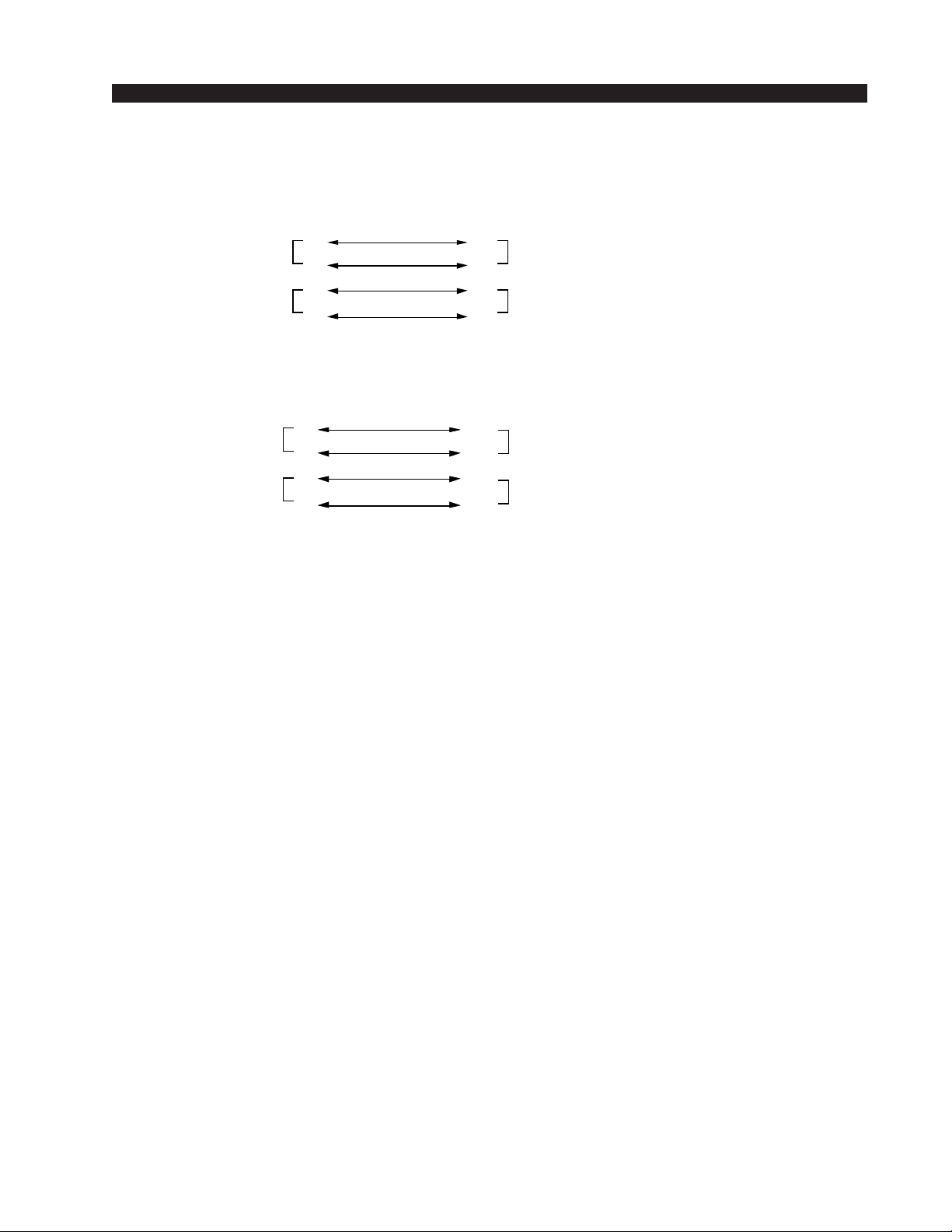
XY Controller RS-485 Cable Pinouts
Connector Type
DB-9
Male
OR
ADR-32 End
XYC I/O
Connector Type
DB-9 Male
Pair 1
Pair 2
Pair 1
Pair 2
PIN
PIN
1
6
3
8
1
6
3
8
TX +
TX -
RX +
RX -
TX +
TX -
RX +
RX -
PIN
PIN
8
21
1
14
1
Pair 1
6
3
Pair 2
Connector Type
DB-9
Male
8
Console End
Pair 1
XY-4/8 module
Connector Type
Pair 2
Upper/Lower
DB-25 Male
ADR-32 / Dec 2002
page 3 – 7
Page 48

CONTROLLER DEVICES
Wheatstone Console Interface
The ADR-32 has a powerful level of integration designed into the system
which allows the user to map specific Wheatstone console input channel
alpha-numeric displays to router destinations. The X-Point Configuration
GUI is used to configure the available console input channels and to map
switcher destinations to their input displays. Please refer to the System
Configuration section in the “X-Point Software Setup Guide” chapter of this
manual for details.
Once the ADR-32 outputs have been “mapped” to console inputs, the
console’s input channel displays will show the name of the router source
currently connected to it. Whenever the channel strip’s input source is
changed, either locally or remotely, its display will update with the new source
name. A/B input source mapping is supported. Further, when a “mapped”
input channel on a console is turned ON and assigned to the PGM output bus,
all XY GUI’s and hardware controllers are updated to show that the channel
input (i.e. router destination) is LOCKED. This ensures that a “live” source
is not accidentally knocked off air or a recording interrupted. Wheatstone
consoles also have the unique ability to recall router sources when a console
preset is taken.
Wheatstone console CPU modules connect to the ADR-32 software via
a dedicated RS-485 serial interface bus. Note that this bus is separate from, and
in addition to, the XY controller bus.
Wheatstone Console RS-485 Connections
Cables that are used for connecting the ADR-32 Router RS-485 serial port
to a Wheatstone console serial port are very similar to XY Controller RS-485
cables. The only difference is the connector type and pinout required for the
console end of the cable. Use the same type of low capacitance computer
communications cable recommended for the XY controllers.
Connect the DB-9 end of the cable to the serial “CONSOLE I/O” Port
DB-9 connector on the cage rear. Connect the DB-25 male end to the console’s
CPU module. Locate the female LDB-25 connector (Lower DB-25 ) mounted
directly beneath the CPU module on the console mainframe’s bottom panel.
It will be labelled with the physical mainframe slot number. The console’s
CPU module is usually installed in slot 30 or 31. Note that there is no LDB
connector for slot 32 (or 24 in 24 position mainframes).
If there is more than one Wheatstone console, parallel the connections at
the first console end of the cable and daisy chain the remaining consoles in a
similar fashion. Be sure to terminate only the last console in the chain.
Console RS-485 Cable Pinouts
ADR-32 End
CONSOLE I/O
Connector Type
DB-9 Male
Pair 1
Pair 2
PIN
1
6
3
8
TX +
TX -
RX +
RX -
PIN
12
11
10
Pair 1
Pair 2
9
Console End
CPU module
Connector Type
Lower DB-25 Male
!
Caution!
Do not confuse this
cable with the XY Controller cable.
ADR-32 / Dec 2002
page 3 – 8
Page 49

CONTROLLER DEVICES
Console CPU Module Settings
Certain dipswitch settings must be made on the connected Wheatstone
consoles in order for them to be recognized by the ADR-32 system software.
These settings are the console address, serial port mode, and RS-485 termination.
Console Address
Each Wheatstone console connected to the system must have a unique
numerical address (e.g. 1, 2, 3, etc.). The console address is set via a bank of
four position dipswitches located on the CPU module. Refer to your console
documentation for details, or contact customer support.
RS-485 Select / Termination
The CPU module also has a pair of four-position dipswitches that select the
serial port mode and RS-485 termination. Locate the RS-485/RS-232 Select
dipswitch and set it OFF for RS-485. If this is the last console in the chain,
locate the RS-485 Termination dipswitch and switch the COM1 positions ON.
Otherwise leave RS-485 Termination for COM1 OFF.
ADR-32 / Dec 2002
page 3 – 9
Page 50

X-POINT SOFTWARE SETUP GUIDE
X-Point Software
Setup Guide
Chapter Contents
ADR-32 Ethernet/IP Address Quick Start....................................4-2
Ethernet Cabling ....................................................................................................... 4-2
Default IP Address.................................................................................................... 4-2
Changing your PC’s IP Address ............................................................................... 4-2
Changing the ADR-32’s IP Address ......................................................................... 4-2
Configuring IP Address in X-Point Software ............................................................ 4-3
Saving the ADR-32 Configuration ............................................................................ 4-3
Getting Started ..............................................................................4-4
GUI Log-In......................................................................................4-4
Passwords ................................................................................................................ 4-4
Tier Configuration .........................................................................4-5
Connection Between the Configuration GUI and ADR-32.........4-6
Signal Definition............................................................................4-9
Important Signal Definition Notes ..............................................4-9a
Signal Locking..............................................................................4-10
Salvo Definition ............................................................................4-11
XY Rack or Console XY Controller Configuration ....................4-12
Console Configuration ................................................................4-13
Special Functions - Console Locks ......................................................................... 4-13
Console Presets ...................................................................................................... 4-13
XY GUI Controller Configuration ................................................4-14
Saving and Loading Configurations .........................................4-14a
Off-line Editing ........................................................................................................ 4-14a
Sending a Configuration to the ADR-32 ................................................................. 4-14a
Main Menu Summary ...................................................................4-15
ADR-32 / Dec 2002
ADR-32 / Jun 2003
page 4 – 1
Page 51

X-POINT SOFTWARE SETUP GUIDE
ADR-32 Ethernet / IP Address
Quick Start
Ethernet Cabling
• Use a CAT 5 crossover ethernet cable to connect a PC directly to the
ADR-32.
• Use a standard CAT5 ethernet cable to connect the ADR-32 to your
network hub.
Default IP Address
The ADR-32 router IP Address is set to 192.168.1.160 at the factory. In
order to connect using the X-Point software, the PC must have a matching
network prefix (i.e 192.168.1.xxx). If your PC's current IP address does not
match you must choose one of the following options:
• change the IP address of the PC running the XPoint software.
or
• change the IP address of the ADR-32 router.
Changing your PC's IP Address
To set your PC's IP address you must access the TCP/IP Properties form for
the network adapter. The exact procedure depends on the specific version of
Windows™ you are running. Generally speaking:
• Navigate to the Settings • Control Panel • Network configuration form.
• Highlight the TCP/IP line item for your PC's ethernet adapter.
• Click the "Properties" button (the TCP/IP Properties form should open).
• Click "Specify an IP Address" (DHCP not supported).
• Enter an IP address in the range of 192.168.1.2 to
192.168.1.254 (excluding .160).
• Enter a Subnet Mask value of 255.255.255.0
When in doubt, check with your Windows ™ documentation or network
administrator for specific details on altering the network adapter's TCP/IP
properties.
Changing the ADR-32's IP Address
To change the ADR-32's IP address, refer to the Network Configuration
Appendix in this manual. You will need the X-Point CD-ROM and a direct
Ethernet connection between a PC and the router using a CAT5 crossover
cable. Once connected proceed as follows:
• Locate and run the network configuration utility program on X-Point
CD-ROM.
ADR-32 / Dec 2002
page 4 – 2
Page 52
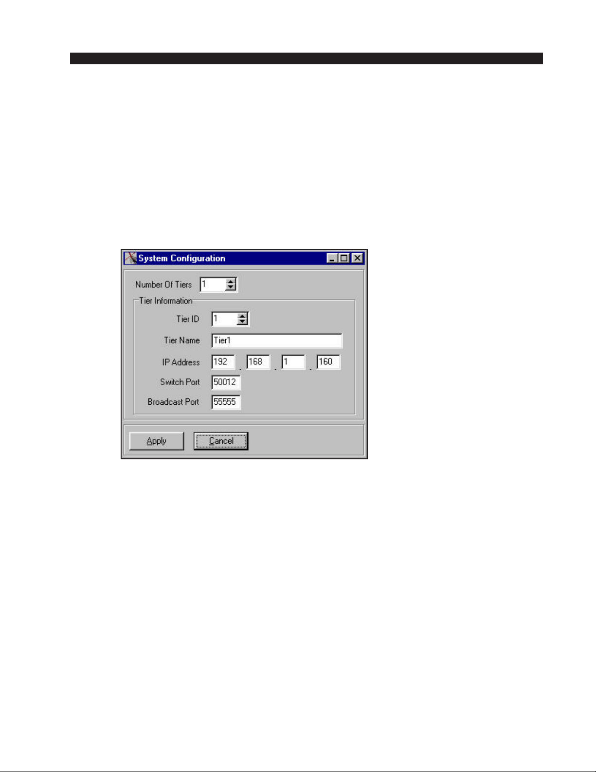
X-POINT SOFTWARE SETUP GUIDE
The filename is AdvXP_Network_Config.exe located in the Network 2.0
folder.
• Carefully follow the instructions in the Network Configuration
Appendix 1.
• Re-boot the ADR-32 (Power down for 10 seconds, power up).
Configuring IP Address in X-Point Software
Next, start the X-Point application, log on as administrator
(password=Admin), and navigate to the Configure•System menu item. The
following form will appear.
Important Note!
This form tells the X-Point software where the ADR-32's CPU
is located on the network.Run
the Network_Config utility to
modify the actual network settings of the ADR-32's CPU.
Important:
• If you changed your PC's IP Address, enter the parameters exactly as
displayed above.
• If you changed the ADR-32's IP Address, enter the parameters you
entered using the Network Configuration Utility program.
If you are connected to the router, you should see a "Connecting to..."
message in the status bar at the bottom of the screen.
Saving the ADR-32 Configuration
Once you connect for the first time be sure to save the configuration.
Choose the File• Save main menu option from the toolbar. When you make
subsequent changes (e.g. rename Sources or Destinations, add controllers,
etc.) be sure to save them.
ADR-32 / Dec 2002
page 4 – 3
Page 53
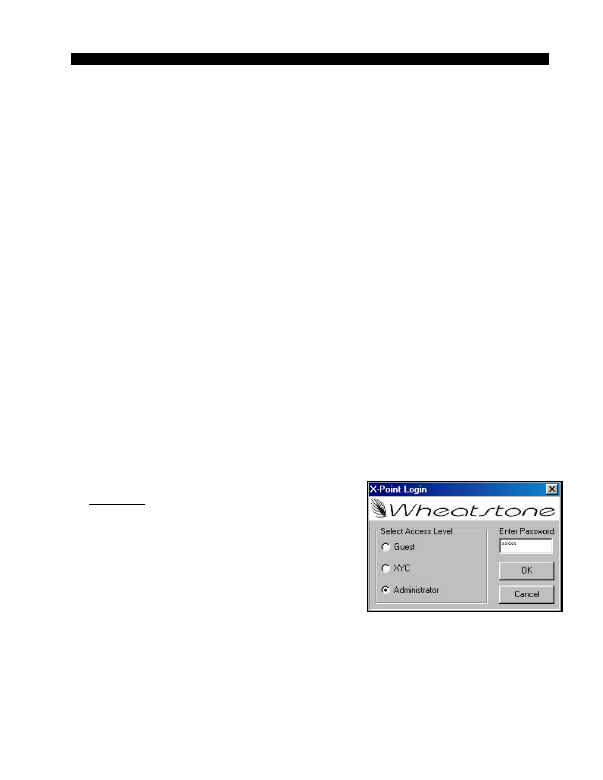
X-POINT SOFTWARE SETUP GUIDE
X-Point Software Setup Guide
Getting Started
All ADR-32 Digital Audio Router hardware is pre-configured at the
factory. This approach greatly speeds the installation process getting you
“online” faster. You may not need to make any software configuration
changes.
After installation and cabling of all required hardware, the system administrator may use the X-Point software to customize the remainder of the
configuration. To install X-Point software be sure that the PC you wish to use
is Windows compliant, has a CD-ROM drive, has at least 50 MB of hard disk
storage available, and has an available ethernet connection. Install the software
on the PC by loading the X-Point CD into the drive tray and then running the
install wizard on the CD by double-clicking on “Setup.exe”.
The following sections will guide the user through all phases of the software
configuration. The main items that may require attention are: any signal
definition changes, source and destination signal naming, XY controller
mapping, and optional Wheatstone console input channel mapping.
Ethernet - The default IP Address of the ADR-32 is 192.168.1.160. Please
see the Ethernet Quick Start preceding this section for details on changing the
ADR-32’s IP Address.
GUI Log-In
Once the X-Point software has been installed and started, a “Log In” dialog
box will be displayed on the screen. There are three possible password
protected log in identities that a user may log in as:
Guest - Allows the user to view screenshot of X-Point only. No switching
of I/O signals.
XYC GUI - Allows the logged in user to select
crosspoints only. Signal visibility must be setup by
Administrator prior to logging in as an XYC GUI.
See the “XY Controller GUI Configuration ” later in
this section for details.
Administrator - allows logged in user complete access to hardware configuration, signal naming, I/O
crosspoint switching, and destination locking.
Passwords
The default passwords are “Xyc” for XYC GUI and “Admin” for Administrator.
Once logged in as Administrator the GUI attempts to connect to the switch
and uploads the current configuration and crosspoint status onto the PC. This
may take 30 seconds or more. Check the lower left hand corner of the screen
for connection status.
ADR-32 / Dec 2002
page 4 – 4
Page 54
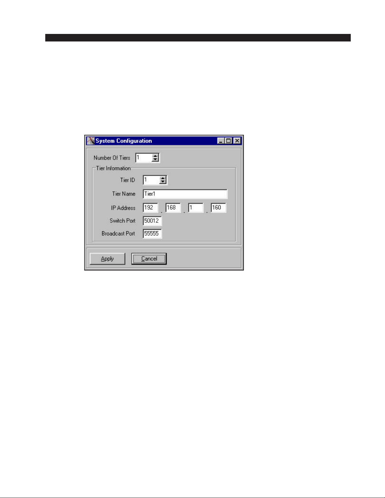
X-POINT SOFTWARE SETUP GUIDE
Tier Configuration
See Quick Start on page 4-2 for details on the System Configuration
form below.
Prior to connecting, the X-Point GUI must be setup with some information regarding the ADR-32's network parameters. A user logged in as
“Administrator” has access to these configuration menus.
Important Note!
This form tells the X-Point software where the ADR-32's CPU
is located on the network.Run
the Network_Config utility to
modify the actual network settings of the ADR-32's CPU - see
Quick Start (p.4-2).
Select 1 for the Number of Tiers in the system. Provide a Tier Name,
the ADR-32’s IP Address, Switch Port, and Broadcast Port used. The
Number of Tiers, IP Address, Switch Port, and Broadcast Port values must
match the current settings of the ADR-32's CPU in order to connect.
The Switch Port will normally be related to the tier using the formula
50NN2, where NN is the two digit tier ID (i.e. 01 for tier 1...15 for tier 15).
After clicking the Apply button the GUI software will be in the “CONNECTING” state, as discussed in the next section. This completes the Tier
Configuration process.
Note:
Number of Tiers is always 1 for an ADR-32.
ADR-32 / Dec 2002
page 4 – 5
Page 55
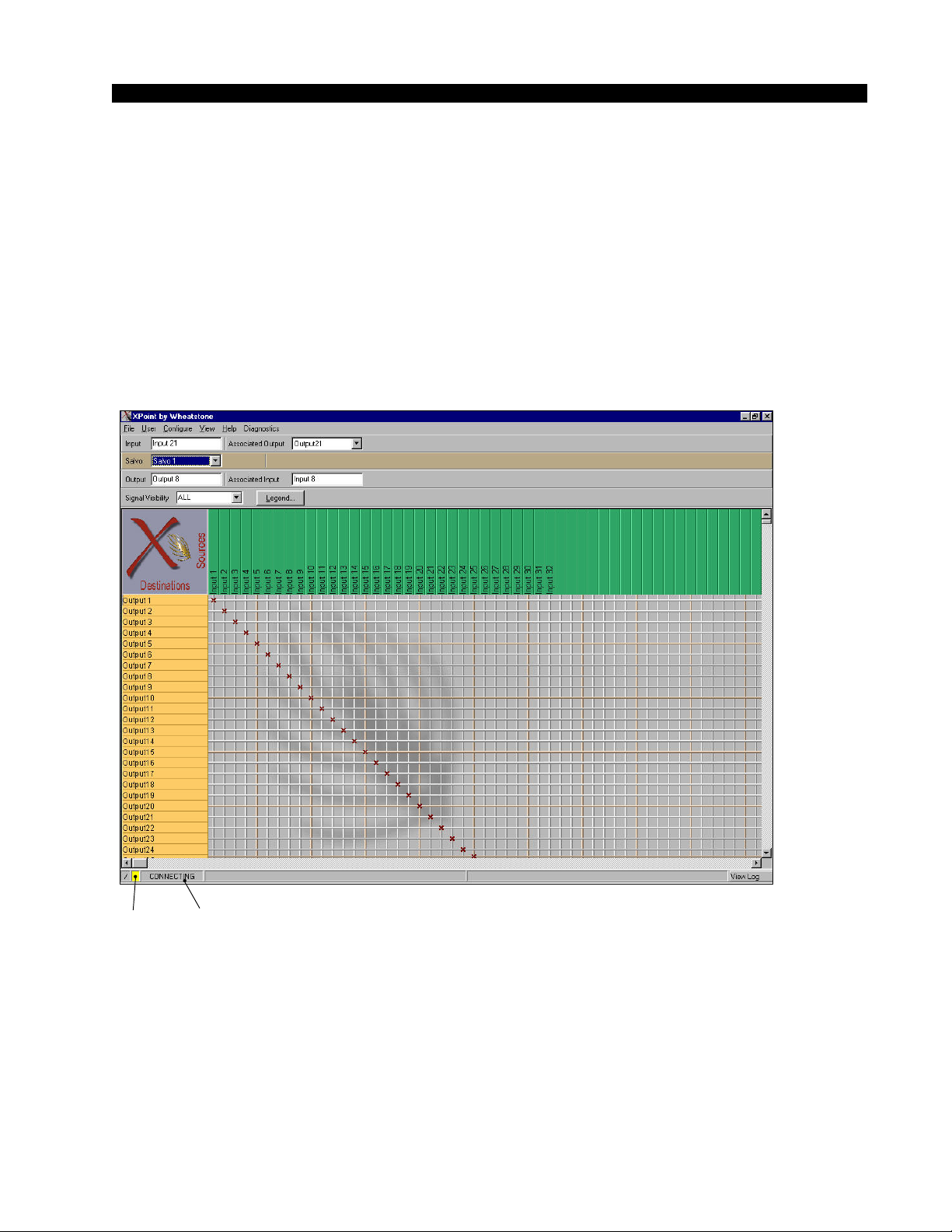
X-POINT SOFTWARE SETUP GUIDE
Connection Between the Configuration GUI and ADR-32
Depending on the state of the system when the current default configuration
files were saved, the Configuration GUI may start in the OFFLINE or
ONLINE mode. While off-line, the GUI does not communicate to the ADR32’s CPU. This is useful to work through initial hardware and signal definitions, which may be downloaded later.
Assuming the default configuration files start the Configuration GUI in
ONLINE mode, a TCP connection to the ADR-32's CPU will be attempted, as
indicated via the status message and yellow status indicator shown below.
Yellow
Status
Indicator
Status
Message
When the GUI successfully communicates with the ADR-32's CPU software it will start receiving the configuration that the ADR-32's CPU has stored
in its nonvolatile memory. While uploading this configuration information the
yellow status indicator turns green and the status message changes from
CONNECTING to something similar to the following (varies with tier name
and IP/address): “Uploading Config From 192.168.1.160 [Tier 1]”.
ADR-32 / Dec 2002
page 4 – 6
Page 56
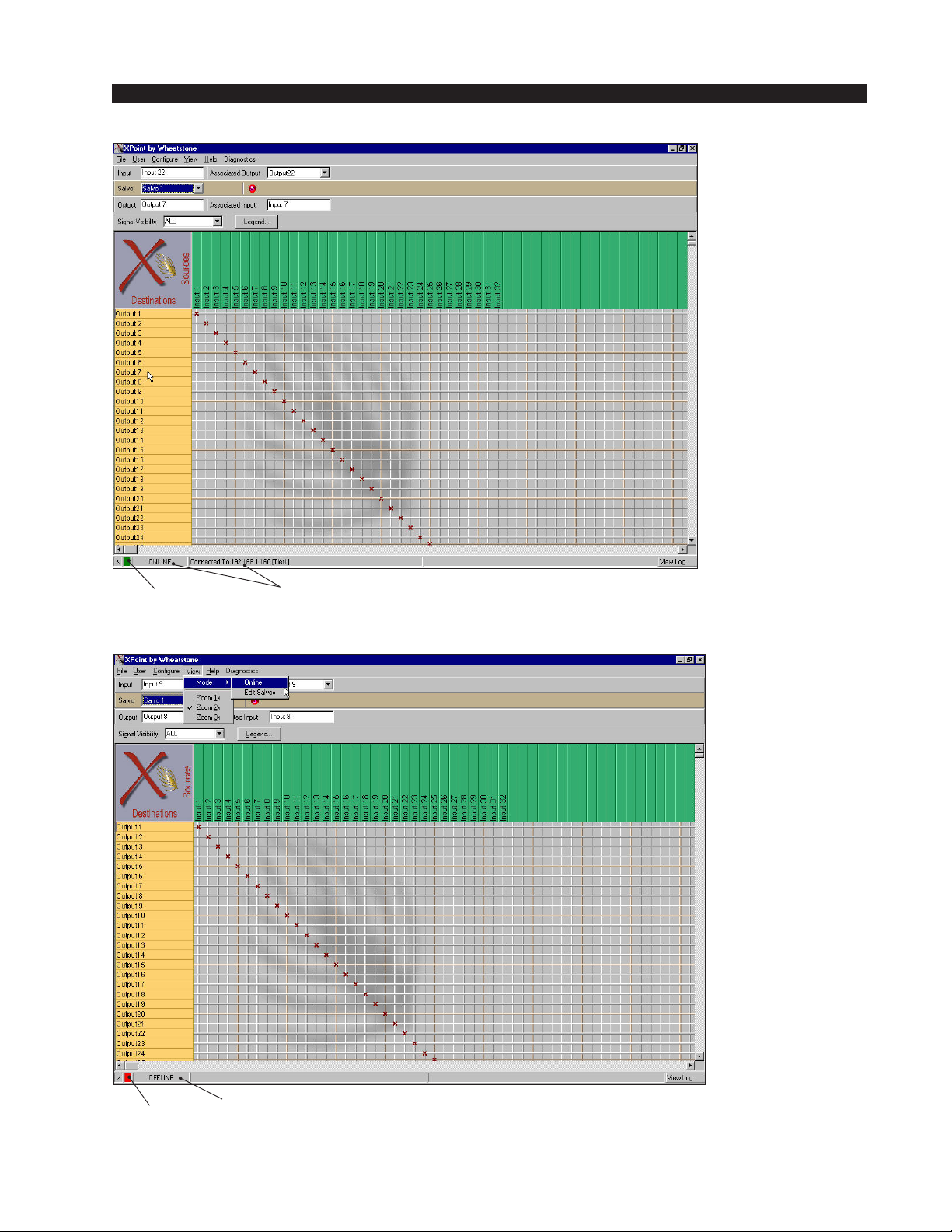
X-POINT SOFTWARE SETUP GUIDE
Once the configuration has been
uploaded the GUI
enters the ONLINE
state as shown to the
left:
Green
Status
Indicator
Status
Message
To disconnect
from the ADR-32's
CPU and go to OFFLINE mode, select
the View / Mode /
Offline menu option.
The status indicator
on the screen will
then change as
shown to the left:
Red
Status
Indicator
ADR-32 / Dec 2002
Status
Message
page 4 – 7
Page 57
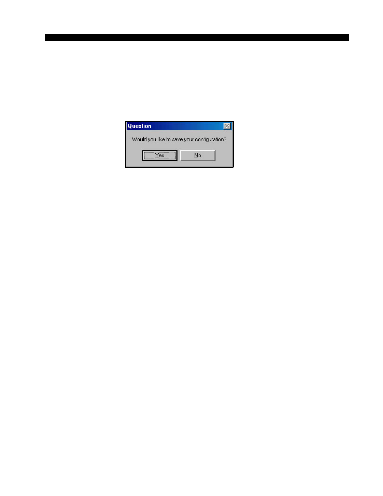
X-POINT SOFTWARE SETUP GUIDE
To connect to the ADR-32's CPU while in OFFLINE mode, select the View
/ Mode / Online menu option. The status indicator on the screen will then change
to CONNECTING as discussed above.
If the user made changes to a few crosspoints in OFFLINE mode and then
goes to ONLINE mode, this message box pops-up:
Choose YES to save OFFLINE changes. The ADR-32 software checks the
request for validity (input to output, output not already assigned, lock flag not
set, etc.). If the request is valid, it is implemented, and the Configuration GUI
is updated. If not valid, the request is rejected with an appropriate reason
message displayed.
ADR-32 / Dec 2002
page 4 – 8
Page 58
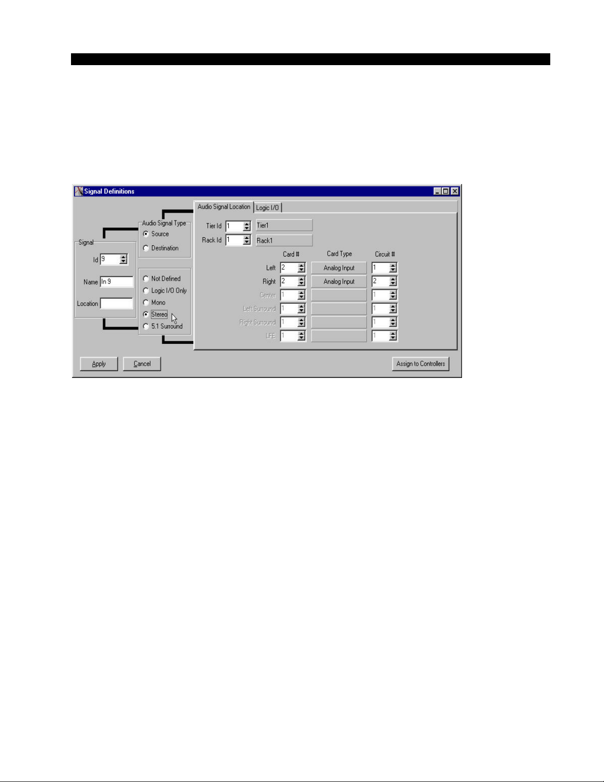
X-POINT SOFTWARE SETUP GUIDE
Signal Definition
Up to 64 separate source and destination signals may be defined via the
Configuration GUI. To add or edit a signal from the GUI’s main grid, right
click on one of the Source or Destination signals and select “Modify Signal
Definition”. The following form will appear:
Note:
Logic I/O not available
on an ADR-32.
! Card# Value
See example below
before entering Card#
value.
Each signal is automatically assigned a unique Signal ID number. For each
Signal ID number the following parameters can be configured:
• Signal Name: Enter the 8 character name to be displayed on XY controllers
and the X-Point GUI.
• Location: Enter an optional 8 character description of the signal’s location.
• Audio Signal Type: Choose Source or Destination.
• Format: Choose Mono, Stereo, or 5.1 Surround.
*Note that the ADR-32 does NOT sum stereo input signals to mono
outputs.
• Audio Signal Location Tab: Defines the signal’s physical location.
• Tier ID & Rack ID will always be 1 for ADR-32 systems
• Card # - valid input slots are 1,2,3 or 4, valid output slots are 5,6,7,8*
• Circuit # - valid choices are 1
*see example below in the Important Signal Definition Notes section
-16, odd#’s are left, even#’s are right*
When defining the Audio Signal Location, remember that X-Point cir-
cuits are equivalent to a single audio channel. Every analog audio card has
four stereo channels (4x2 channels = 8 circuits). Digital cards have 8 stereo
channels, or 16 circuits.
ADR-32 / Dec 2002
ADR-32 / Jun 2003
page 4 – 9
Page 59

X-POINT SOFTWARE SETUP GUIDE
Important Signal Definition Notes
Audio Format: The ADR-32 ships pre-configured as a 32x32 stereo router.
If you plan on configuring MONO signals please note the following. A MONO
input will route to any MONO output or to both channels of a stereo output. A
STEREO input will route only the left or right channel to a mono output. The
exact channel depends on which circuit # was used for the MONO output, odd
circuits = left, even circuits = right. The alternative to this method is to leave the
ADR-32 configured as stereo and bridge mono sources across both the left/right
inputs. Mono outputs may be derived using external summing resistors, see
note in the analog output hardware section.
Card Type : All slots will report “Analog Input” or Analog Output” for the
Card Type, even if you have digital i/o cards installed. This is normal.
Card # : The Card # value is based on 4 virtual input slots and 4 virtual output
slots. This provides a maximum of 32 stereo inputs (4 virtual slots X 8 stereo
channels) and 32 stereo outputs. When entering the Card# note that 2 physical
analog input or output cards are considered to be a single Card #. This is because
there are only 4 stereo inputs or outputs on an analog card versus 8 stereo inputs
or outputs on a digital card.
Card # and Circuits Example:
You have installed analog input cards in physical slots #1, 2 and 3 and a
digital input card in physical slot #5.
Analog stereo inputs 1-4 are in physical slot#1; Card# = 1, Circuits =1-8
Analog stereo inputs 5-8 are in physical slot #2; Card # = 1, Circuits = 9-16
Analog stereo inputs 9-12 are in physical slot #3; Card # = 2, Circuits = 1-8
Digital stereo inputs 17-24 are in physical slot #5; Card# = 3, Circuits =1-16
Note that in the example above, there is a gap in between the analog input
card installed in physical slot #3 and the digital input card installed in physical
slot #5. The gap is physical slot #4 which may be loaded only with an analog
input card in the future. Values for this future card would be:
Analog stereo inputs 13-16 are in physical slot #4; Card # = 2, Circuits = 9-16
The rear panel of the ADR-32 clearly labels which card types may be
installed in a particular slot. When configuring the ADR-32 it is important to
remember that the ADR-32 is limited to a maximum of 4 virtual input cards and
4 virtual output cards. A fully loaded all digital box would have 4 physical input
cards and 4 physical output cards. A fully loaded all analog box would have 8
physical input cards and 8 physical output cards.
ADR-32 / Dec 2002
ADR-32 / Jun 2003
page 4 – 10
page 4 – 9a
Page 60
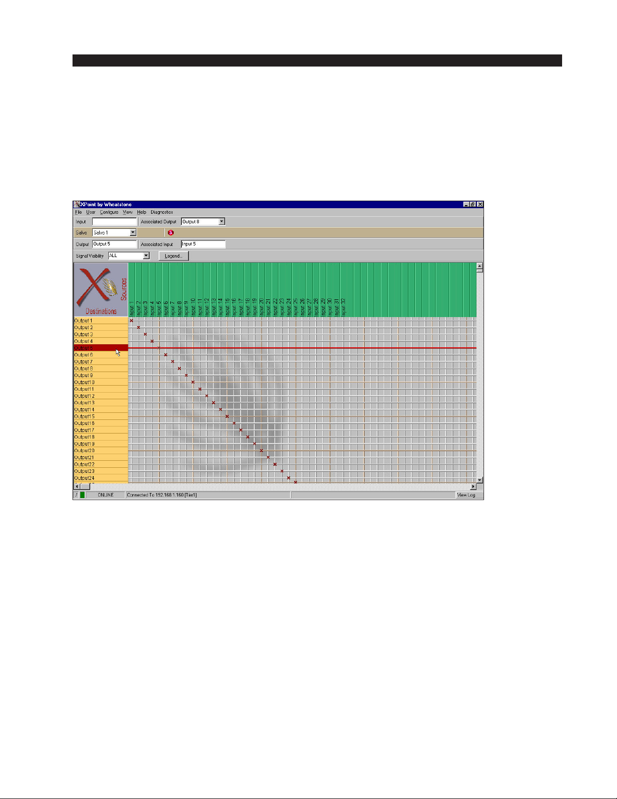
X-POINT SOFTWARE SETUP GUIDE
Signal Locking
To lock a signal, right click on one of available output channels on the
crosspoint grid and select “Lock Connection”:
That crosspoint output signal becomes locked as indicated by red line through
the signal on the GUI display and shown on form below:
To Unlock a connection, right click on the destination and select “Unlock
Connection”.
ADR-32 / Dec 2002
page 4 – 10
Page 61
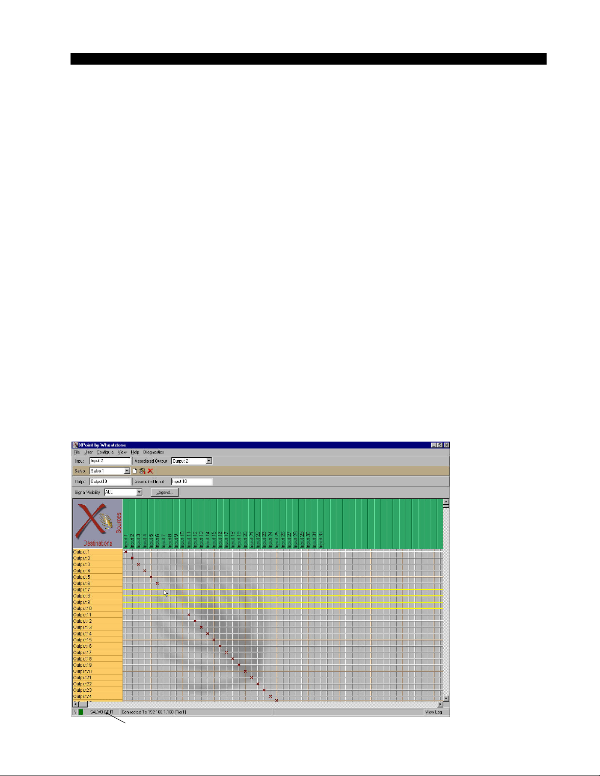
X-POINT SOFTWARE SETUP GUIDE
Salvo Definition
Macro control of the ADR-32 router is accomplished by creating and
firing Salvos. A Salvo is simply a group of cross connects, disconnects and
“do nothings” that occur when the selected Salvo is fired. Each Salvo has a
unique name and can be programmed to be visible to any hardware XY
controller or XYC GUI.
To define a Salvo, use the Configuration GUI and enter Salvo Edit Mode
by selecting the View / Mode / Edit Salvos Edit menu. The operator may then
choose to modify the grid connections in an existing Salvo, or use the Salvo
toolbar icons to rename an existing Salvo or to create a new one. By making
and breaking connections on the crosspoint grid, the operator builds up a
Salvo definition. The order in which Salvo actions are created determines
the “playback” order.
When completed, the operator leaves Salvo Edit Mode, at which point the
newly defined Salvos are available for use. If the application is connected to
a switch (ON-LINE mode) the new Salvo definitions are automatically sent
to the switch. It is a good idea to save the newly created Salvos on the PC by
choosing File / Save... from the main menu.
Note that clicking on the Delete Salvo icon in the Salvo Toolbar will
initially delete all the connections defined in a Salvo; a subsequent click on
this button will delete the Salvo from the Salvo list. This is a useful way to
clear out an existing Salvo and then redefine the connections within that
Salvo. To cancel changes made to a Salvo select View / Mode / Cancel Salvo
Edits from the main menu.
An example of Salvo Edit mode is shown below:
ADR-32 / Dec 2002
Status Message
<-Salvo Tool Bar
• Rename Salvo
• New Salvo
• Clear/Delete Salvo
Caution!
A yellow line through a connection means the connection will be switched OFF
when the Salvo is fired.
page 4 – 12
page 4 – 11
Page 62
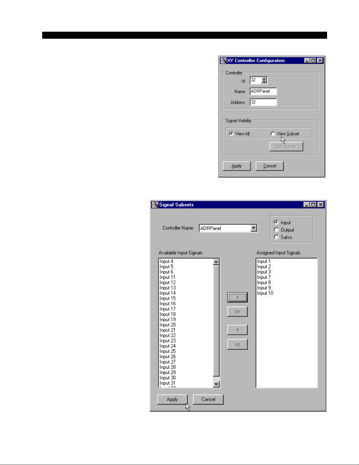
X-POINT SOFTWARE SETUP GUIDE
XY Rack or Console XY Controller Configuration
To configure a hardware based XY Controller, the
operator must first log-in to the GUI as an Administrator. Next, select the Configure / Controller Configura-
tion menu option, which will display the form at the
right.
For each XY Controller in the system, provide a
name and an unique RS-485 address between 1 and 63.
Note that the XY controller addresses were pre-configured in hardware at the factory and their unique
address is momentarily displayed on power up. See the
“Hardware” chapter for addressing details if necessary.
Also decide whether each controller will have access to the entire I/O signal space, View All, or just a
subset, View Subset. If a subset is
selected, the following form will
be displayed.
The next step is to set the
Input, Output, and Salvo visibility options by choosing Input,
Output, or Salvo. Next highlight
the desired signal(s) or salvo(s)
in the left column, then click on
the single right arrow box (>)
found between the columns. In
order to make all signals or salvos visible click the double right
arrow (>>) box found between
the columns. The left arrow buttons are to remove signal(s) or
salvo(s) from the visible list found
in the right column.
ADR-32 / Dec 2002
page 4 – 13
page 4 – 12
Page 63
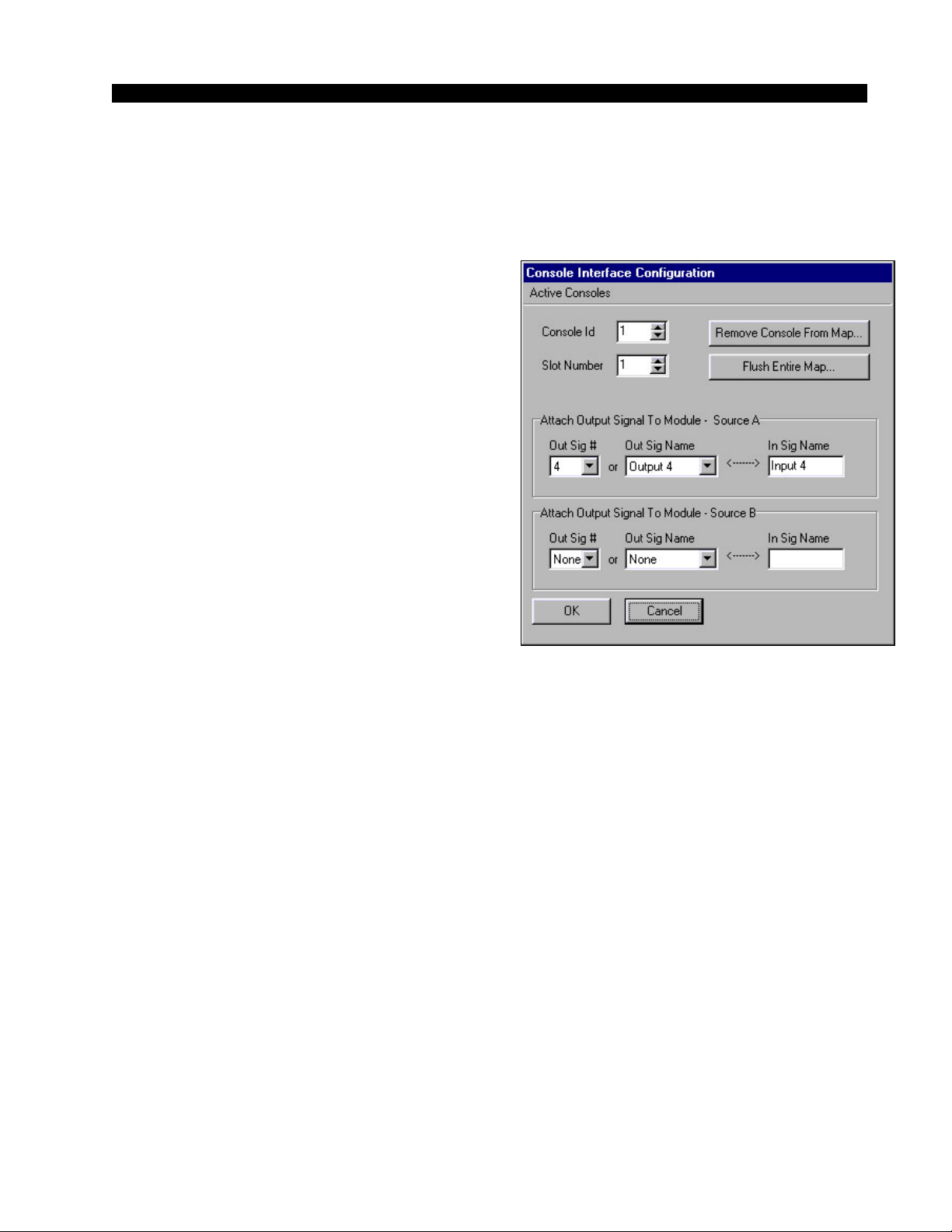
X-POINT SOFTWARE SETUP GUIDE
Console Configuration
To map crosspoint output signals to console input channels the operator must
first log in to the GUI as an Administrator. Then select the Configure / Console
Interface menu option, which will display the
following form.
Each module in a console is identified via the
“Console Id” and “Slot Number” spin edit boxes.
The user can select from any of the available router
output signals and assign a signal to Source A and
another signal to Source B of a console’s input
module. The input signal (if any) that is currently
connected to the selected output signal is displayed in the “In Sig Name” text box. This is the
name that will appear on the module’s LED display once the map has been sent to the switch
software. As the module’s Source button is toggled
between source A and source B, the LED names
displayed on the module will toggle with it.
The Active Consoles menu item brings up a
dialog box to set the range of console addresses the
router will communicate with. Choices are First,
Last and Default console ID’s. The active console
range should be set to the smallest number of
consoles to avoid unnecessary system communication latency.
Special Functions - Console Locks
If a crosspoint output signal is mapped to a console module and that module
is “ON AIR”, that crosspoint output signal becomes console-locked, as indicated
by a blue line through the signal on the GUI display. When a signal is consolelocked its connection to a crosspoint input cannot be changed. To change this
connection, take the module “OFF AIR” then choose a different source.
Whenever a signal is removed from the console map, any “ON-AIR” locks
are automatically removed. This prevents a console-lock from being “stuck on”
with no way to remove it.
Console Presets
If a console has the ability to save a Preset, the switch software will save the
current connection information for all output signals that are currently mapped
to that console. The next time that console activates that preset the connections
that existed at the time the preset was saved are restored. However, if a module
is ON-AIR when the Preset is taken, that connection will not be made. This
ensures that activating a preset will not disturb any ON-AIR signals.
If the user changes the crosspoint-output-signal-to-console mapping, the
Presets for that console may be invalidated. The user should go through and resave the presets on that console after changing the console map!
ADR-32 / Dec 2002
page 4 – 14
page 4 – 13
Page 64
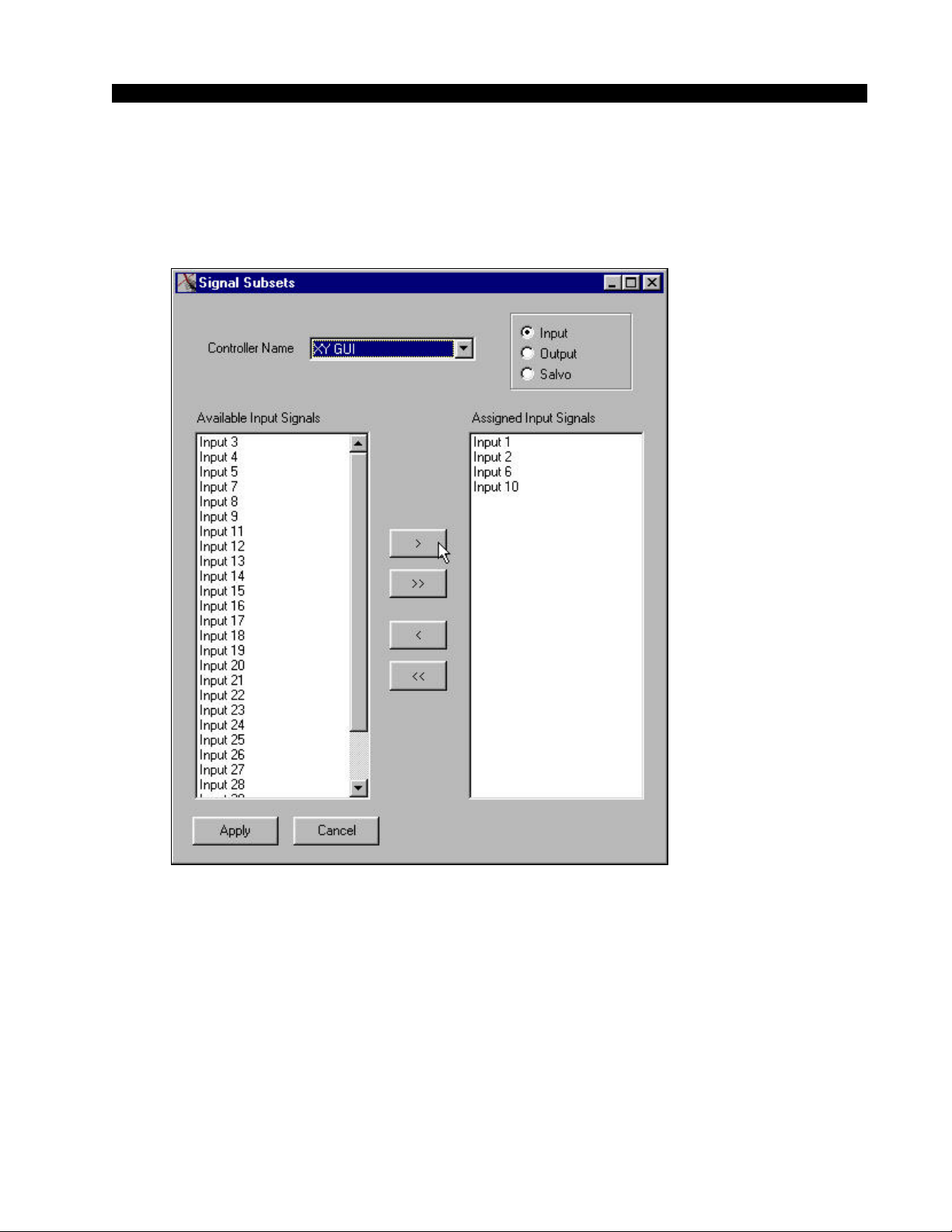
X-POINT SOFTWARE SETUP GUIDE
XY GUI Controller Configuration
In order to configure an XY GUI the operator must first log-in to the GUI
as an administrator. Then select the User / XY GUI Setup menu option, which
will display the following form.
XY GUI - mode allows
multiple PC’s to make
connections across an
ethernet network.
The next step is to set the input, output, and salvo visibility options by
choosing Input, Output, or Salvo. Next highlight the desired signal(s) or
salvo(s) in the left column, then click on the single right arrow box (>) found
between the columns. In order to make all signals or salvos visible click the
double right arrow (>>) box found between the columns. The left arrow
buttons are to remove signal(s) or salvo(s) from the visible list found in the right
column. Clicking the Apply button will save the visibility options.
ADR-32 / Dec 2002
page 4 – 15
page 4 – 14
Page 65

X-POINT SOFTWARE SETUP GUIDE
Saving and Loading Configurations
The ADR-32 stores its current configuration on an internal solid state hard
drive. Use the File menu choices to save the current configuration on your PC
or to upload an existing configuration from your PC to the ADR-32.
Saving a configuration is fairly straight forward. Select File• Save from the
menu bar and select a folder to save the configuration in.
Off-line Editing
To Load a previously saved configuration while in OFFLINE mode (not
connected to the ADR-32), select File•Open from the menu bar and select the
appropriate folder. Click on the Apply button and the configuration is now
loaded in to the X-Point software for review or editing.
Sending a Configuration to the ADR-32
To Load a previously saved configuration and upload it to the ADR-32,
while in ONLINE mode (connected to the ADR-32), select File•Open from the
menu bar and select the appropriate folder. Be sure to uncheck the Tier Name/
Address check box and then click the Apply button. Next, select File• Send
Config to Switch from the menu bar. The configuration is now loaded into the
ADR-32. Any signal definition, XY controller visibility settings, etc. are
updated and stored in the ADR-32 memory.
Caution! Because you must be ONLINE to send a configuration to the
ADR-32, be sure to disable or temporarily halt the use of external XY
controllers. If an XY controller is switched while sending a configuration, the
ADR-32 memory may be partially loaded or corrupted, thus requiring a
complete re-configuration. You may disable external XY controllers by
simply removing the RS-485 DB-9 connector on the rear of the ADR-32.
ADR-32 / Dec 2002
ADR-32 / Jun 2003
page 4 – 16
page 4 – 14a
Page 66

X-POINT SOFTWARE SETUP GUIDE
Main Menu Summary
The following is a summary of all the available menu choices when logged into
X-Point as the Administrator.
File Menu
Open : Opens the Load Configuration form. Loads previously saved configuration
elements for off-line viewing/editing or download to ADR-32's CPU.
Save : Opens the Save Configuration form. Saves any or all changes.
Send Cfg To Switch : Initiates download of currently loaded configuration to the
ADR-32's CPU module. Use this to update the system hardware with config changes.
Exit : Exits the X-Point program.
User Menu
LogIn/LogOut : Opens the X-Point Log-in form if currently logged out, else logs out
if logged in.
Change Password : Allows the Administrator to change the XYC or Admin access
level Log-in passwords.
XY GUI Setup : Used to configure source/destination signal visibility of this machine
when logged in at the XYC access level.
Configure Menu
System : Configure TCP/IP network and Host port parameters.
XY Controller Configuration : Used to define and configure hardware based XY
controllers present in the system. Access XYC Signal Visibility editing here.
Console Interface : Used to define and configure optional Wheatstone console input
channel display mapping.
View Menu
Mode-OffLine : Select OFFLINE to edit configuration. Be sure to Save configuration
prior to returning ONLINE. This menu option is only available if you are currently
ONLINE.
Mode-Online : Initiates network connection to ADR-32's CPU, uploads Host
configuration once connected. View real time status of all crosspoints. This menu option
is only available if you are currently OFFLINE.
Mode-Salvo Edit : Create, define and edit Salvos in this mode. This menu option is
only available if you are not in Salvo edit mode.
Mode-Leave Salvo Edit : Exit Salvo Edit mode. This menu option is only available
if you are in Salvo Edit mode.
Mode-Cancel Salvo Edits : Cancels any edits made in Salvo Edit mode and exits
Salvo Edit mode. This menu option is only available if you are in Salvo Edit mode.
Zoom 1x-2x-3x : Zoom in and out of X-Point grid.
Help Menu
How To... : Opens help hints text file.
About : Shows X-Point software revision.
ADR-32 / Dec 2002
page 4 – 17
page 4 – 15
Page 67
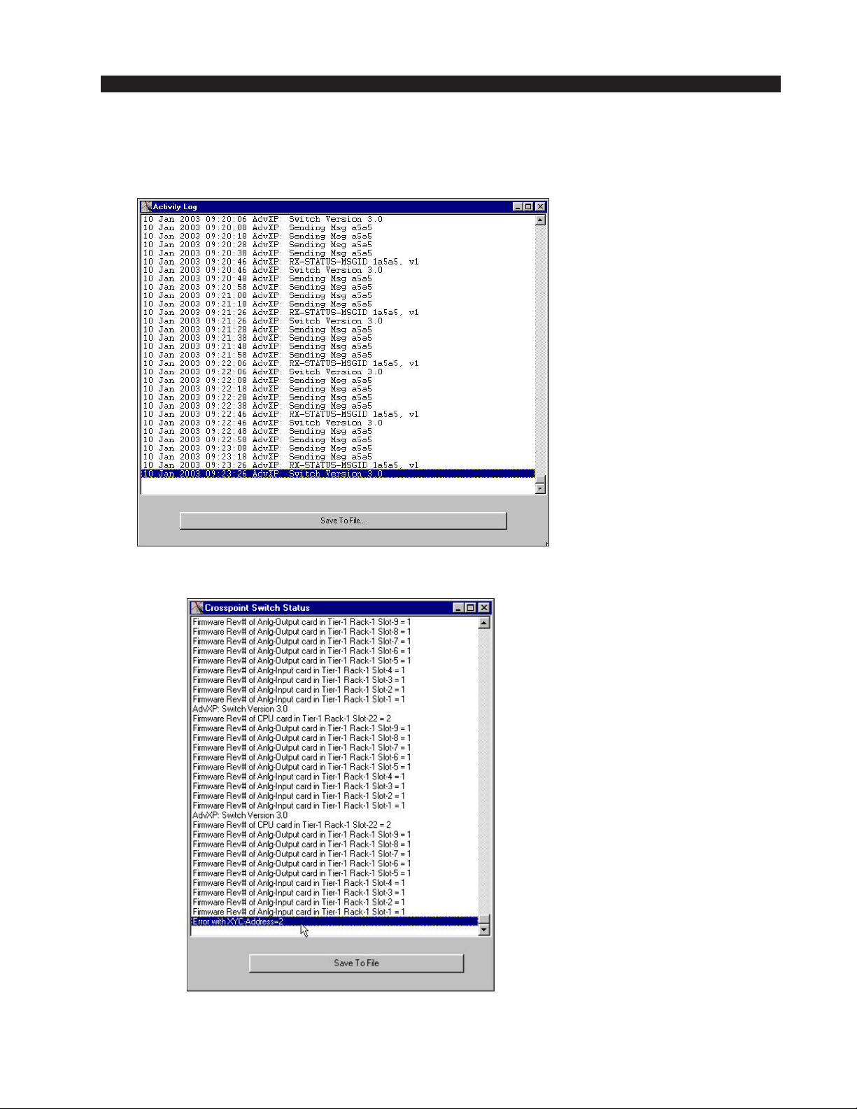
X-POINT SOFTWARE SETUP GUIDE
Diagnostics Menu
View App Log : Opens network communications activity log. Can save log
to a file for technical support purposes.
View Switch Status : Lists all active installed hardware, card firmware
revisions.
Reset Switch : Initiates an ADR-32's CPU reboot. Use this function with
caution!
ADR-32 / Dec 2002
page 4 – 16
Page 68

S C H E M A T I C D R A W I N G S
I/O Schematic Drawings
Chapter Contents
4 Analog Inputs Card Schematic (ADC-4) .............................................................. 5-2
4 Analog Inputs Card Load Sheet (ADC-4)............................................................. 5-4
4 Analog Outputs Card Schematic (AO-4).............................................................. 5-5
4 Analog Outputs Card Load Sheet (AO-4) .............................................................5-7
8 Digital Inputs Card Schematic (SRC-8)................................................................5-8
8 Digital Outputs Card Load Sheet (SRC-8) .......................................................... 5-10
8 Digital Outputs Card Schematic (DO-8).............................................................. 5-11
8 Digital Outputs Card Load Sheet (DO-8) ............................................................ 5-12
Processor Board Schematic (PR-32) ..................................................................... 5-13
Processor Board Load Sheet (PR-32).................................................................... 5-18
ADR-32 / Dec 2002
page 5 – 1
Page 69
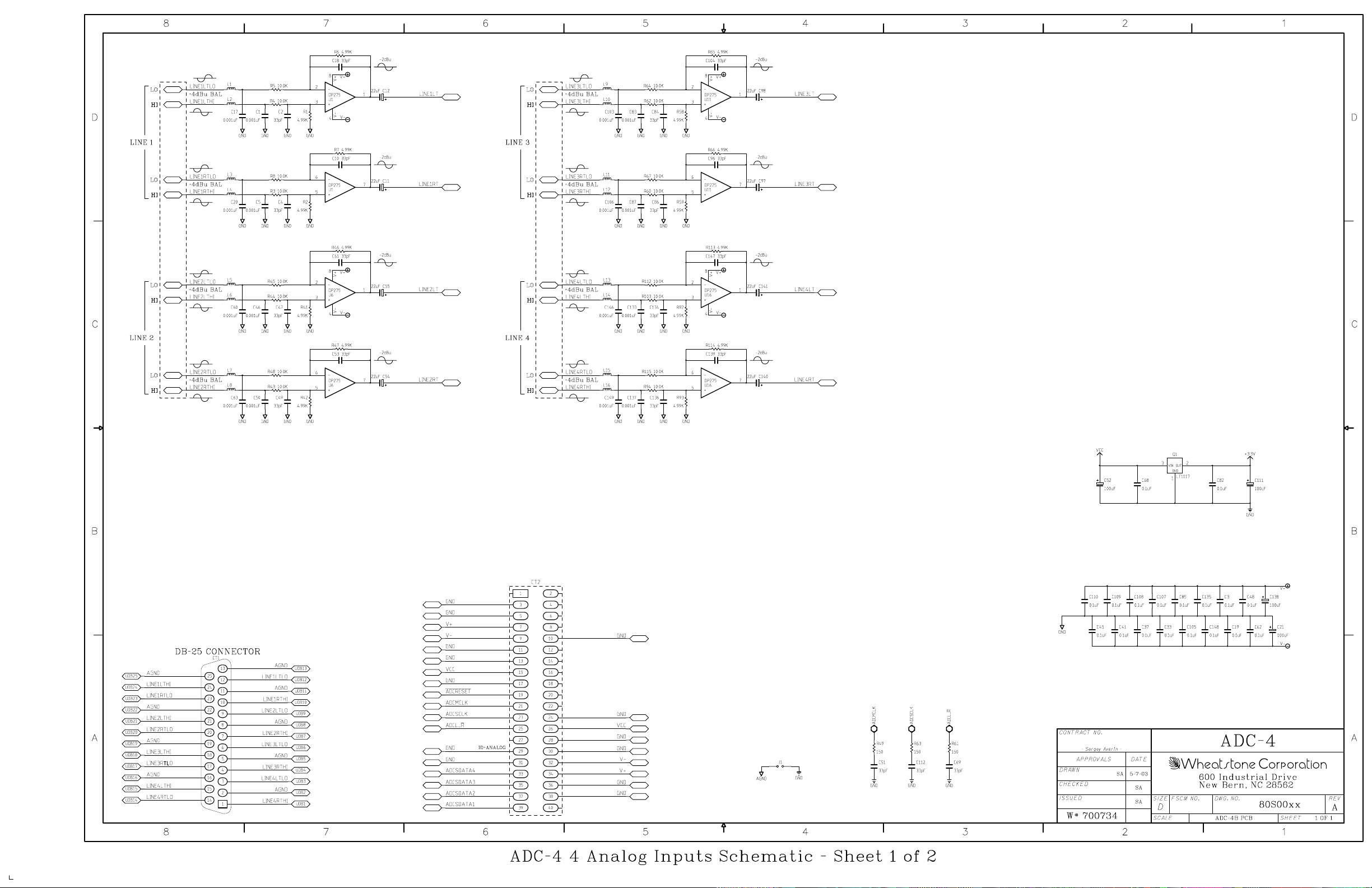
ADR-32/May 2003
page 5 - 2
Page 70
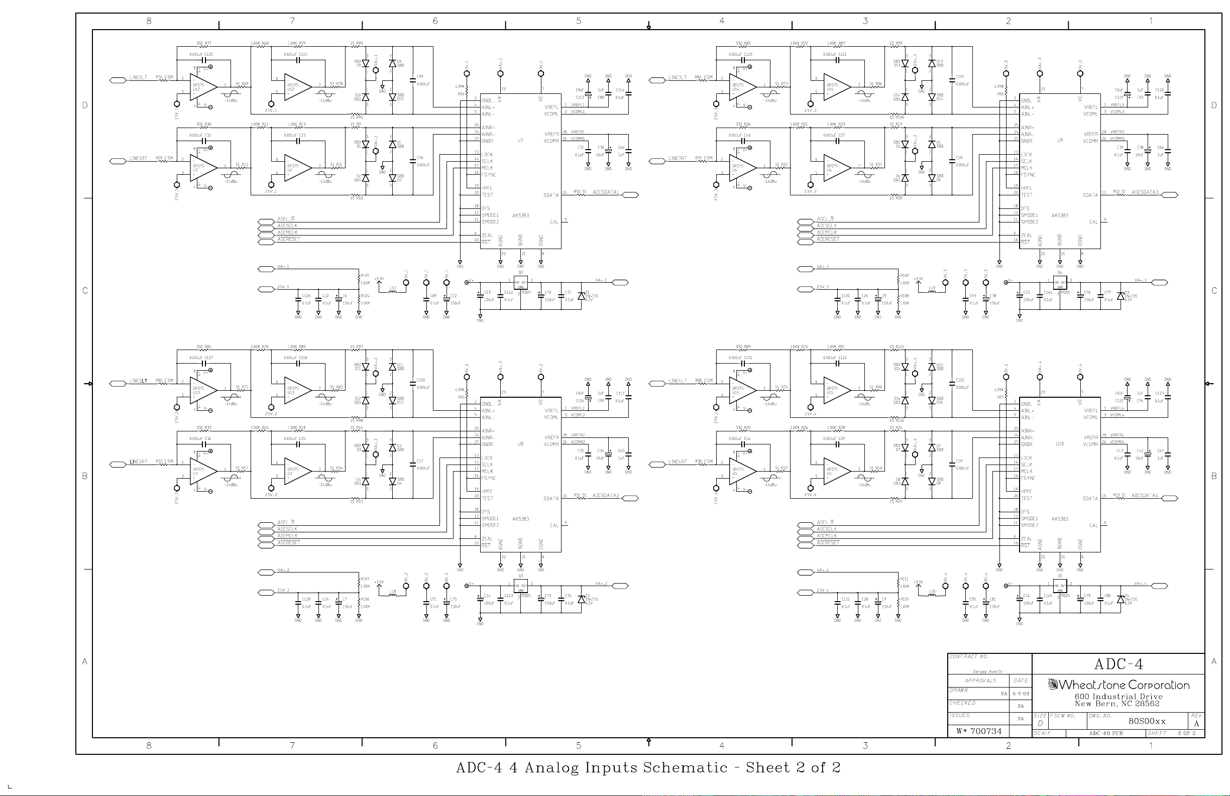
ADR-32/May 2003
page 5 - 3
Page 71
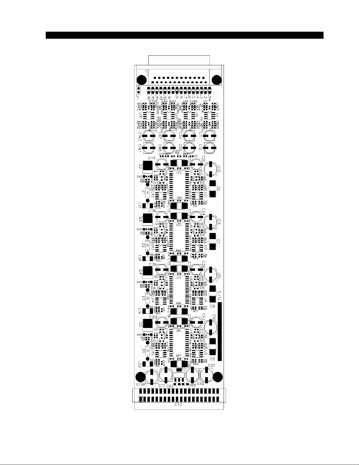
S C H E MA T IC D R A W I N G S
ADR-32 / Dec 2002
4 Analog Inputs Card (ADC-4) - Load Sheet
page 5 – 2
page 5 – 4
Page 72
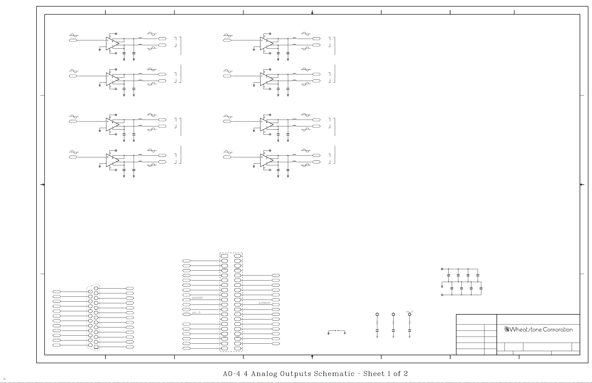
8
7
6
5
4
3
2
1
D
C
-2dBu
-2dBu
-2dBu
-2dBu
OUTPT1LT
OUTPT1RT
OUTPT2LT
OUTPT2RT
GND
GND
GND
GND
V+
6
U1
SSM2142
gnd
5
6
U2
SSM2142
gnd
5
6
U7
SSM2142
gnd
5
6
U8
SSM2142
gnd
5
7
8
1
2
V-
GND
V+
7
8
1
2
V-
GND
V+
7
8
1
2
V-
GND
V+
7
8
1
2
V-
GND
4
3
4
3
4
3
4
3
C23
68pF
C25
68pF
C42
68pF
C43
68pF
L1
LINE1LTHI LINE3LTHI
+4dBu BAL
L3
LINE1LTLO
C9
68pF
GND
L2
LINE1RTHI LINE3RTHI
+4dBu BAL
L4
LINE1RTLO
C11
68pF
GND
L5
LINE2LTHI LINE4LTHI
+4dBu BAL
L7
LINE2LTLO
C28
68pF
GND
L6
LINE2RTHI LINE4RTHI
+4dBu BAL
L8
LINE2RTLO
C29
68pF
GND
HI
LT
LO
LINE 1 LINE 3
HI
RT
LO
HI
LT LT
LO
LINE 2
HI
RT
LO
-2dBu
-2dBu
-2dBu
-2dBu
OUTPT3LT
OUTPT3RT
OUTPT4LT
OUTPT4RT
GND
GND
GND
GND
V+
6
U9
SSM2142
gnd
5
6
U10
SSM2142
gnd
5
6
U15
SSM2142
gnd
5
6
U16
SSM2142
gnd
5
7
8
1
2
V-
GND
V+
7
8
1
2
V-
GND
V+
7
8
1
2
V-
GND
V+
7
8
1
2
V-
GND
4
3
4
3
4
3
4
3
C70
68pF
C71
68pF
C96
68pF
C98
68pF
GND
GND
GND
GND
C52
68pF
C53
68pF
C88
68pF
C90
68pF
L9
L11
L10
L12
L13
L15
L14
L16
+4dBu BAL
LINE3LTLO
+4dBu BAL
LINE3RTLO
+4dBu BAL
LINE4LTLO
+4dBu BAL
LINE4RTLO
HI
LO
HI
LO
HI
LO
HI
LO
LT
RT
LINE 4
RT
D
C
B
A
UDB25
UDB24
UDB23
UDB22
UDB21
UDB20
UDB19
UDB18
UDB17
UDB16
UDB15
UDB14
DB-25 CONNECTOR
AGND
LINE1LTHI
LINE1RTLO
AGND
LINE2LTHI
LINE2RTLO
AGND
LINE3LTHI
LINE3RTLO
AGND
LINE4LTHI
LINE4RTLO
8
B
CT2
2
GND
GND
V+
VGND
CT1
13
25
12
24
11
23
10
22
9
21
8
20
7
19
6
18
5
17
4
16
3
15
2
14
1
AGND
LINE1LTLO
AGND
LINE1RTHI
LINE2LTLO
AGND
LINE2RTHI
LINE3LTLO
AGND
LINE3RTHI
LINE4LTLO
AGND
LINE4RTHI
UDB13
UDB12
UDB11
UDB10
UDB9
UDB8
UDB7
UDB6
UDB5
UDB4
UDB3
UDB2
UDB1
7
GND
VCC
GND
DACMCLK
DACSCLK
GND
GND
DACSDATA4
DACSDATA3
DACSDATA2
DACSDATA1
ID=ANALOG
6
1
4
3
56
78
9
10
11 12
13 14
15 16
17 18
19
20
21 22
23 24
25 26
27 28
29
30
31 32
33 34
35 36
37 38
39
40
GND
DIF0
DIF1
DIF2
DEM1
DEM0
GND
VCC
GND
GND
GND
GND
V+
C99
C12
0.1uF
C26
GND
0.1uF
V-
DACMCLK
V-
V+
5
AGND
J1
GND
4
GND
DACSCLK
R3
150
C30
33pF
GND
R6
150
C31
33pF
GND
R2
150
C27
33pF
3
C97
0.1uF
0.1uF
C91
C89
0.1uF
0.1uF
CONTRACT NO.
- Sergey Averin -
DRAWN
CHECKED
W# 700736
SA
C24
0.1uF
C10
0.1uF
5-30-03
2
AO-4
A
DATEAPPROVALS
600 Industrial Drive
SA
SA
D
New Bern, NC 28562
DWG. NO.FSCM NO.ISSUED
AO-4A PCB
80S00xx
REVSIZE
SHEETSCALE
A
1 OF 1
1
ADR-32/May 2003
page 5 - 5
Page 73
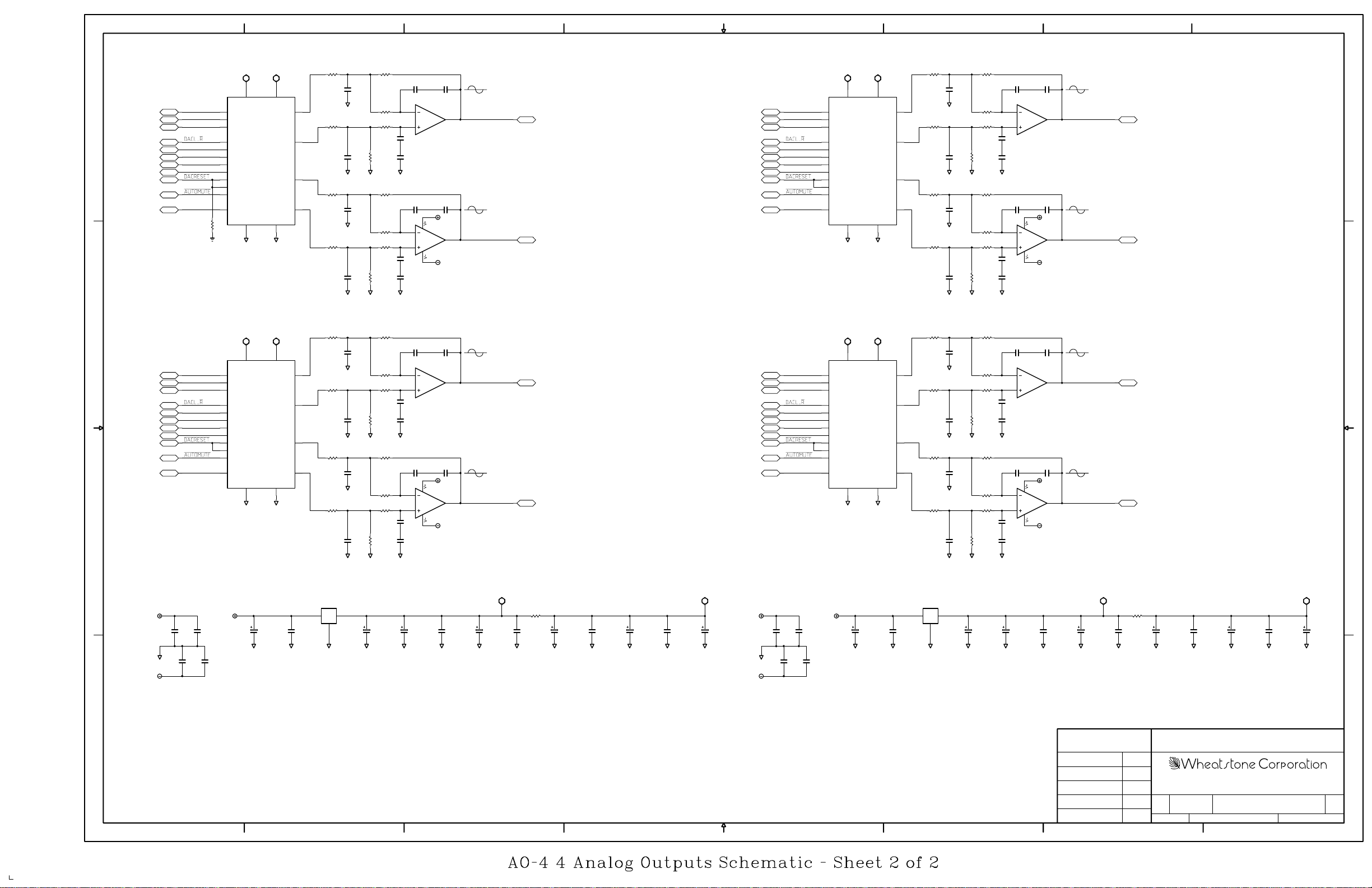
8
7
6
5
4
3
2
1
D
C
B
DIF0
DIF1
DIF2
DACSCLK
DACSDATA1
DEM0
DEM1
DACMCLK
R1
4.99K
GND
DIF0
DIF1
DIF2
DACSCLK
DACSDATA2
DEM0
DEM1
DACMCLK
VD+01 VA+01
6
VD+
20
DIF0
19
DIF1
12
DIF2
7
LRCK
9
SCLK
10
SDATA
1
DEM0
2
DEM1
_______
15
MUTE_R
_______
16
MUTE_L
___________
11
AUTO_MUTE
8
MCLK
DGND
54
GND
VD+01 VA+01 VD+23 VA+23
6
VD+
20
DIF0
19
DIF1
12
DIF2
7
LRCK
9
SCLK
10
SDATA
1
DEM0
2
DEM1
_______
15
MUTE_R
_______
16
MUTE_L
___________
11
AUTO_MUTE
8
MCLK
DGND
54
GND
U3
CS4390
U4
CS4390
3
VA+
AOUTL-
AOUTL+
AOUTR-
AOUTR+
AGND
GND
3
VA+
AOUTL-
AOUTL+
AOUTR-
AOUTR+
AGND
GND
17
18
13
14
17
18
13
14
R475.76K R3916.5K
C100
2200pF
GND
C101
R40
2200pF
16.5K
GND
R75.76K
C32
2200pF
GND
R85.76K
C33
R16
2200pF
16.5K
GND
R495.76K R4116.5K
C102
2200pF
GND
C103
R42
2200pF
16.5K
GND
R95.76K
C34
2200pF
GND
R105.76K
C35
R18
2200pF
16.5K
GND
GND
GND
GND
GND
R311.30K
R321.30KR485.76K
390pF
390pF
R1516.5K
R231.30K
R241.30K
390pF
390pF
R331.30K
R341.30KR505.76K
390pF
390pF
R1716.5K
R251.30K
R261.30K
390pF
390pF
C80390pF C72390pF
-2dBu
6
OP275
U11
5
C73
C81
GND
C44390pF C54390pF
V+
8
2
OP275
U11
3
C55
4
V-
C45
GND
C82390pF C74390pF
6
OP275
U12
5
C75
C83
GND
C46390pF C56390pF
V+
8
2
OP275
U12
3
C57
4
V-
C47
GND
OUTPT1LT
7
-2dBu
OUTPT1RT
1
-2dBu
OUTPT2LT
7
-2dBu
OUTPT2RT
1
DIF0
DIF1
DIF2
DACSCLK
DACSDATA3
DEM0
DEM1
DACMCLK
DIF0
DIF1
DIF2
DACSCLK
DACSDATA4
DEM0
DEM1
DACMCLK
20
DIF0
19
DIF1
12
DIF2
7
LRCK
9
SCLK
10
SDATA
1
DEM0
2
DEM1
_______
15
MUTE_R
_______
16
MUTE_L
___________
11
AUTO_MUTE
8
MCLK
20
DIF0
19
DIF1
12
DIF2
7
LRCK
9
SCLK
10
SDATA
1
DEM0
2
DEM1
_______
15
MUTE_R
_______
16
MUTE_L
___________
11
AUTO_MUTE
8
MCLK
VD+23 VA+23
6
VD+
3
U5
VA+
AOUTL-
AOUTL+
AOUTR-
AOUTR+
DGND
AGND
CS4390
54
GND
GND
6
VD+
3
U6
VA+
AOUTL-
AOUTL+
AOUTR-
AOUTR+
DGND
AGND
CS4390
54
GND
GND
R515.76K R4316.5K
R351.30K
R361.30KR525.76K
390pF
390pF
R1916.5K
R271.30K
R281.30K
390pF
390pF
R371.30K
R381.30KR545.76K
390pF
390pF
R2116.5K
R291.30K
R301.30K
390pF
390pF
C84390pF C76390pF
-2dBu
6
OP275
U13
5
C77
C85
GND
C48390pF C58390pF
V+
8
2
OP275
U13
3
C59
4
V-
C49
GND
OUTPT3LT
7
-2dBu
OUTPT3RT
1
D
C
C86390pF C78390pF
-2dBu
6
OP275
U14
5
C79
C87
GND
C50390pF C60390pF
V+
8
2
OP275
U14
3
C61
4
V-
C51
GND
OUTPT4LT
7
-2dBu
OUTPT4RT
1
B
C104
2200pF
17
18
13
14
17
18
13
14
GND
C105
R44
2200pF
16.5K
GND
R115.76K
C36
2200pF
GND
R125.76K
C37
R20
2200pF
16.5K
GND
R535.76K R4516.5K
C106
2200pF
GND
C107
R46
2200pF
16.5K
GND
R135.76K
C38
2200pF
GND
R145.76K
C39
R22
2200pF
16.5K
GND
GND
GND
GND
GND
A
ADR-32/May 2003
GND
Q1
2
C64
0.1uF
V+
C94
1uF
V+
C65
C63
0.1uF
0.1uF
C62
0.1uF
V-
GND
1
OUTIN
GND
C92
0.1uF
PQ05SZ
3
GND GNDGNDGNDGND GND
C40
22uF
C1
1uF
C13
0.1uF
C3
1uF
GND GND
C15
0.1uF
R410
C21
22uF
C14
0.1uF
C2
1uF
GNDGNDGND
GND
VD+01VA+01 VD+23VA+23
C68
0.1uF
V+
C95
1uF
GND
C16
0.1uF
V+
C4
1uF
GND
V-
C67
0.1uF
C66
0.1uF
C69
0.1uF
Q2
2
1
OUTIN
GND
C93
0.1uF
PQ05SZ
3
GND GNDGNDGNDGND GND
C41
22uF
C5
1uF
C17
0.1uF
C7
1uF
GND GND
CONTRACT NO.
- Sergey Averin -
C19
0.1uF
R510
C22
22uF
C18
0.1uF
C6
1uF
GNDGNDGND
AO-4
GND
C20
0.1uF
C8
1uF
A
DATEAPPROVALS
DRAWN
CHECKED
W# 700736
8
7
6
5
4
3
SA
5-30-03
2
SA
SA
D
600 Industrial Drive
New Bern, NC 28562
DWG. NO.FSCM NO.ISSUED
80S00xx
AO-4A PCB
REVSIZE
SHEETSCALE
A
2 OF 2
1
page 5 - 6
Page 74
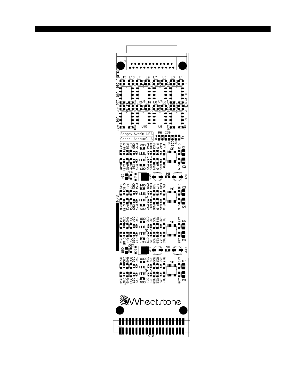
SCHEMATIC DRAWINGS
ADR-32 / Dec 2002
4 Analog Outputs Card (AO-4) - Load Sheet
page 5 – 3
page 5 – 7
Page 75
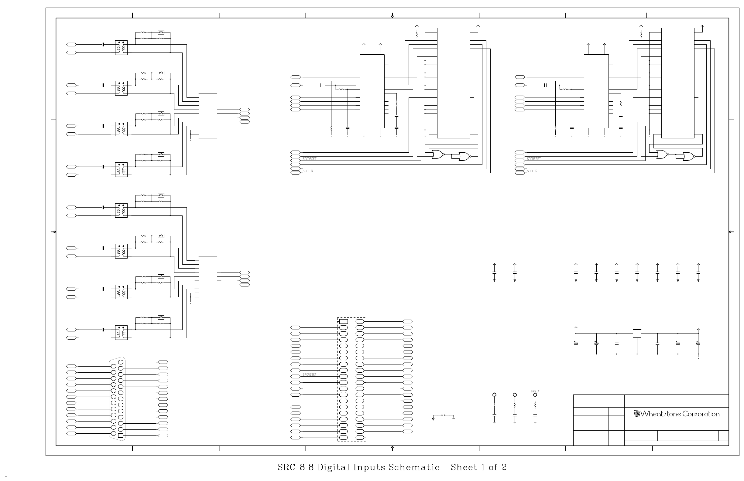
D
C
8
LINE1_D_HI
LINE1_D_LO
LINE2_D_HI
LINE2_D_LO
LINE3_D_HI
LINE3_D_LO
LINE4_D_HI
LINE4_D_LO
T1
0.1uFC15
34
1
T2
0.1uFC16
3
1
T3
0.1uFC34
1
T4
0.1uFC35
3
1
VDD_IO
SDATA_O
SCLK_O
LRCLK_O
MCLK_O
MUTE_O
2
U10
3
74ACT02
1
VCC
720
23
25
24
D
3
15
1
C
U17
CS8414
VCC
VD+
VERF
CBL
ERF
SDATA
SCK
FSYNC
FILT
__
C0/E0
Ca/E1
Cb/E2
Cc/F0
Cd/F1
Ce/F2
GNDGND
2
VCC
R56
1.00K
7
1
C
14
U
28
15
25
26
12
20
6
1.00K
5
R44
4
3
C53
2
0.1uF
27
C44
0.1uF
8
GND
GND
5
6
TDM_I
4
SDATA_I
5
SCLK_I
6
LRCLK_I
10
SMODE_I_0
11
SMODE_I_1
12
SMODE_I_2
19
SMODE_O_0
18
SMODE_O_1
17
WLNGTH_O_0
16
WLNGTH_O_1
2
MCLK_I
26
MMODE_I_0
27
MMODE_I_1
28
MMODE_I_2
1
GRPDLYS
______
13
RESET
9
BYPASS
14
MUTE_I
U10
74ACT02
U21
AD1896
4
7
SW1
R5 150
R6 150
FOR 75 OHM
6
R7 150
R8 150
FOR 75 OHM
4
6
R21 150
R22 150
FOR 75 OHM
43
6
R23 150
R24 150
FOR 75 OHM
4
6
21
R19 33
SW2
12
R20 33
SW3
12
R27 33
SW4
21
R28 33
GND
6
A+
7
A-
10
B+
9
B-
14
C+
15
C-
2
D+
1
D-
4
EN
___
12
EN
U7
OUTA
OUTB
OUTC
OUTD
AM26C32A
LINE1D
5
LINE2D
11
LINE3D
13
LINE4D
3
6
SRCFCLK
C26 0.01uF
LINE1D
SRCAESM0
SRCAESM2
SRCAESM3
R1
4.99K
GND
SRCMCLK
SRCGPDLYS
SRCSCLK
SRCSDATA1
R10 1.00K
C6
0.01uF
GND
5
VCC
22
VA+
19
MCK
13
FCK
16
SEL
9
RXP
RXN
23
M0
24
M1
18
M2
17
M3
AGND DGND
CS8414
21
U3
VCC
VD+
VERF
CBL
ERF
SDATA
SCK
FSYNC
FILT
__
C0/E0
Ca/E1
Cb/E2
Cc/F0
Cd/F1
Ce/F2
GNDGND
VCC
R25
1.00K
7
1
C
14
U
28
15
25
26
12
1110
20
6
1.00K
5
R9
4
3
C5
2
0.1uF
27
C1
0.1uF
8
GND
4
20 7
TDM_I
4
SDATA_I
5
SCLK_I
6
LRCLK_I
10
SMODE_I_0
11
SMODE_I_1
12
SMODE_I_2
19
SMODE_O_0
18
SMODE_O_1
17
WLNGTH_O_0
16
WLNGTH_O_1
2
MCLK_I
26
MMODE_I_0
27
MMODE_I_1
28
MMODE_I_2
1
GRPDLYS
______
13
RESET
9
BYPASS
14
MUTE_I
GND
8
10
U10
9
74ACT02
U8
AD1896
VDD_IO
SDATA_O
SCLK_O
LRCLK_O
MCLK_O
MUTE_O
11
U10
12
74ACT02
VCC
23
25
24
3
15
13
3
SRCFCLK
LINE5D
SRCAESM0
SRCAESM1SRCAESM1
SRCAESM2
SRCAESM3
SRCMCLK
SRCGPDLYS
SRCSCLK
SRCSDATA5
C72 0.01uF
4.99K
VCC
22
VA+
19
MCK
13
FCK
16
SEL
9
R45 1.00K
C54
R36
0.01uF
GND
10 11
23
24
18
17
GND
RXP
RXN
M0
M1
M2
M3
AGND DGND
21
B
A
UDB25
UDB24
UDB23
UDB22
UDB21
UDB20
UDB19
UDB18
UDB17
UDB16
UDB15
UDB14
LINE5_D_HI
0.1uFC49
LINE5_D_LO
LINE6_D_HI
0.1uFC50
LINE6_D_LO
LINE7_D_HI
0.1uFC78
LINE7_D_LO
LINE8_D_HI
0.1uFC79
LINE8_D_LO
DB-25 CONNECTOR
AGND
LINE1_D_HI
LINE2_D_LO
AGND
LINE3_D_HI
LINE4_D_LO
AGND
LINE5_D_HI
LINE6_D_LO
AGND
LINE7_D_HI
LINE8_D_LO
8
R31 150
T5
1
T6
3
1
T7
34
1
T8
3
1
R32 150
43
6
R33 150
R34 150
4
6
R52 150
R53 150
6
R54 150
R55 150
4
6
CT1
13
25
12
24
11
23
10
22
9
21
8
20
7
19
6
18
5
17
4
16
3
15
2
14
1
LINE1_D_LO
LINE2_D_HI
LINE3_D_LO
LINE4_D_HI
LINE5_D_LO
LINE6_D_HI
LINE7_D_LO
LINE8_D_HI
FOR 75 OHM
FOR 75 OHM
FOR 75 OHM
FOR 75 OHM
AGND
AGND
AGND
AGND
AGND
SW5
12
R40 33
SW6
21
R41 33
SW7
21
R58 33
SW8
12
R59 33
UDB13
UDB12
UDB11
UDB10
UDB9
UDB8
UDB7
UDB6
UDB5
UDB4
UDB3
UDB2
UDB1
U16
6
A+
7
A-
10
B+
9
B-
OUTA
14
C+
OUTB
15
C-
OUTC
2
D+
OUTD
1
D-
4
EN
___
12
EN
AM26C32A
GND
7
LINE5D
5
LINE6D
11
LINE7D
13
LINE8D
3
CT2
2
GND
GND
V+
VGND
GND
VCC
GND
SRCMCLK
SRCSCLK
SRCL_~R
ID=DIGITAL
ID_DIG
GND
SRCSDATA4
SRCSDATA3
SRCSDATA2
SRCSDATA1
6
1
4
3
56
78
9
10
11 12
13 14
15 16
17 18
19
20
21 22
23 24
25 26
27 28
29
30
31 32
33 34
35 36
37 38
39
40
5
SRCSDATA5
SRCSDATA6
SRCSDATA7
SRCSDATA8
GND
SRCGPDLYS
SRCAESM0
SRCAESM1
SRCAESM2
SRCAESM3
SRCFCLK
GND
VCC
GND
GND
GND
GND
V-
V+
AGND
J1
GND
4
+3.3V
GND
SRCMCLK
GND
+3.3V
C73
0.1uF
R29
150
C37
33pF
GND
SRCSCLK
GND
C30
0.1uF
R30
150
C42
33pF
GND
R35
150
C43
33pF
3
VCC
GND
VCC
C71
0.1uF
C25
100uF
VCC
GND
CONTRACT NO.
- Sergey Averin -
DRAWN
CHECKED
W# 700733
C63
0.1uF
C32
1uF
VCC
GND
C33
0.1uF
VCC
GND
C38
0.1uF
GND
VCC
C62
0.1uF
VCC
GND
C18
0.1uF
VCC
GND
C17
0.1uF
B
Q1
3
2
OUTIN
GND
LT1117
1
C36
0.1uF
C48
0.1uF
SRC-8
DATEAPPROVALS
SA
5-14-03
2
SA
SA
D
600 Industrial Drive
New Bern, NC 28562
DWG. NO.FSCM NO.ISSUED
SRC-8A PCB
+3.3V
C61
1uF
80S0022
SHEETSCALE
1
GND
C70
100uF
A
REVSIZE
A
1 OF 2
ADR-32/May 2003
page 5 - 8
Page 76
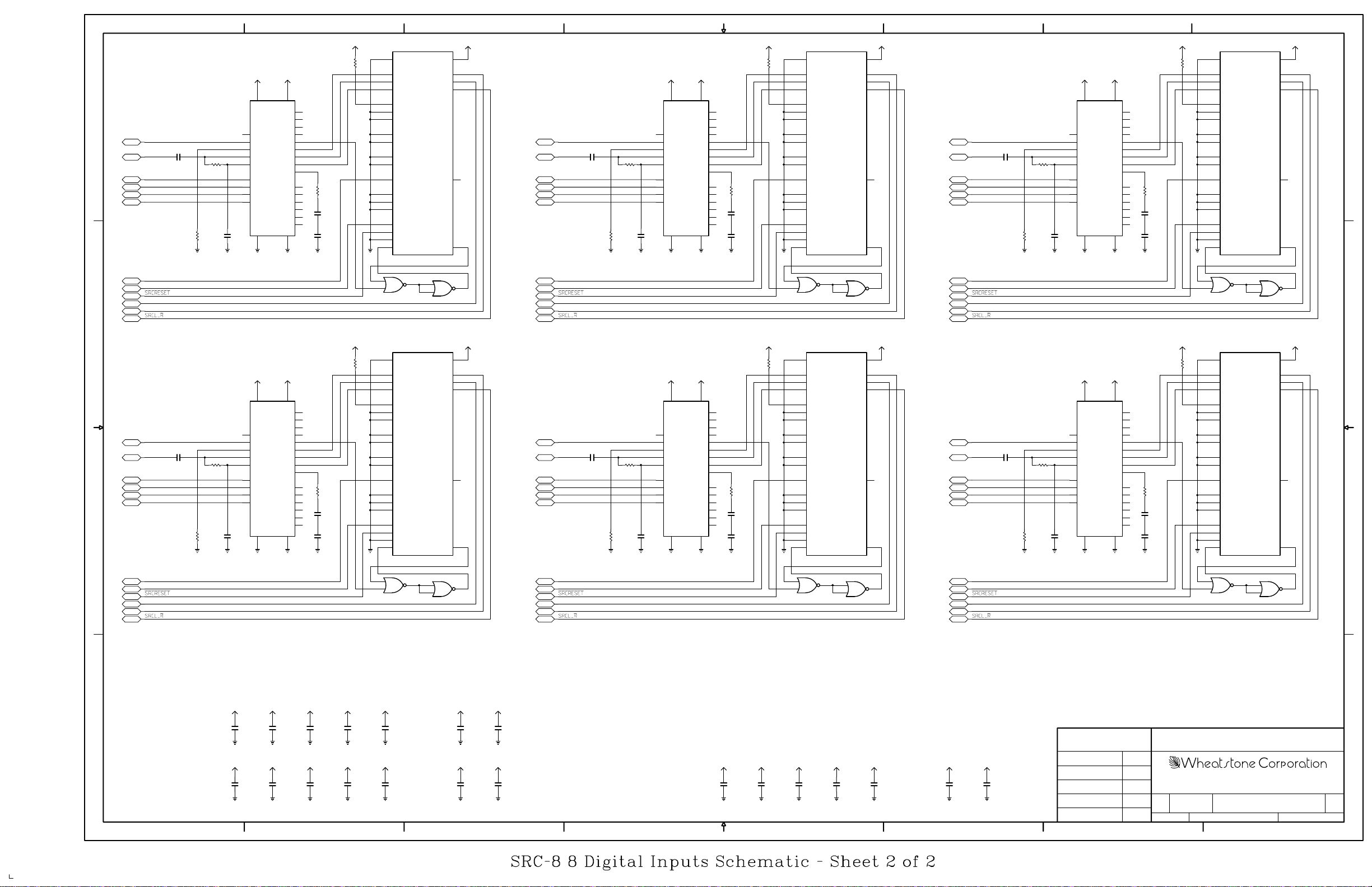
D
8
VCC
VCC
22
VA+
19
GND
MCK
13
FCK
16
SEL
9
RXP
RXN
23
M0
24
M1
18
M2
17
M3
AGND DGND
21
SRCFCLK
C27 0.01uF
LINE2D
SRCAESM0
SRCAESM1 SRCAESM1 SRCAESM1
SRCAESM2
SRCAESM3
SRCMCLK
SRCGPDLYS
SRCSCLK
SRCSDATA2
4.99K
1.00KR13
C8
R2
0.01uF
GND
U4
CS8414
VD+
VERF
CBL
ERF
SDATA
SCK
FSYNC
FILT
__
C0/E0
Ca/E1
Cb/E2
Cc/F0
Cd/F1
Ce/F2
GNDGND
7
8
7
VCC
R11
1.00K
1
C
14
U
28
15
25
26
12
1110
20
6
1.00K
5
R12
4
3
C7
2
0.1uF
27
C2
0.1uF
GND
GND
8
9
74ACT02
U1
20 7
TDM_I
4
SDATA_I
5
SCLK_I
6
LRCLK_I
10
SMODE_I_0
11
SMODE_I_1
12
SMODE_I_2
19
SMODE_O_0
18
SMODE_O_1
17
WLNGTH_O_0
16
WLNGTH_O_1
2
MCLK_I
26
MMODE_I_0
27
MMODE_I_1
28
MMODE_I_2
1
GRPDLYS
______
13
RESET
9
BYPASS
14
MUTE_I
VDD_IO
SDATA_O
SCLK_O
LRCLK_O
MCLK_O
MUTE_O
AD1896
U11
U11
12
11
10
74ACT02
6
VCC
23
25
24
SRCFCLK
C28 0.01uF
LINE3D
3
15
13
SRCAESM0
SRCAESM2
SRCAESM3
SRCMCLK
SRCGPDLYS
SRCSCLK
SRCSDATA3
4.99K
R3
GND
0.01uF
5
VCC
R26
GND
1.00K
R14
C9
0.1uF
C3
0.1uF
1.00K
VCC
VCC
22
VA+
19
MCK
13
FCK
16
SEL
9
GND
RXP
RXN
23
M0
24
M1
18
M2
17
M3
AGND DGND
21
1.00KR15
C10
U5
CS8414
VD+
VERF
CBL
ERF
SDATA
SCK
FSYNC
FILT
__
C0/E0
Ca/E1
Cb/E2
Cc/F0
Cd/F1
Ce/F2
GNDGND
7
1
C
14
U
28
15
25
26
12
1110
20
6
5
4
3
2
27
8
4
20 7
TDM_I
4
SDATA_I
5
SCLK_I
6
LRCLK_I
10
SMODE_I_0
11
SMODE_I_1
12
SMODE_I_2
19
SMODE_O_0
18
SMODE_O_1
17
WLNGTH_O_0
16
WLNGTH_O_1
2
MCLK_I
26
MMODE_I_0
27
MMODE_I_1
28
MMODE_I_2
1
GRPDLYS
______
13
RESET
9
BYPASS
14
MUTE_I
GND
8
10
U12
9
74ACT02
U9
AD1896
VDD_IO
SDATA_O
SCLK_O
LRCLK_O
MCLK_O
MUTE_O
11
U12
12
74ACT02
VCC
23
25
24
3
15
13
3
SRCFCLK
LINE4D
SRCAESM0
SRCAESM2
SRCAESM3
SRCMCLK
SRCGPDLYS
SRCSCLK
SRCSDATA4
C29 0.01uF
4.99K
U2
SDATA_O
LRCLK_O
11
12
VDD_IO
SCLK_O
MCLK_O
MUTE_O
U13
74ACT02
1
VCC
720
23
25
24
D
3
15
13
2
VCC
R16
GND
1.00K
R17
C11
0.1uF
C4
0.1uF
1.00K
VCC
VCC
22
VA+
19
MCK
13
FCK
16
SEL
9
10 11
23
24
18
17
GND
RXP
RXN
M0
M1
M2
M3
AGND DGND
21
1.00KR18
R4
C12
0.01uF
GND
U6
CS8414
VD+
VERF
CBL
ERF
SDATA
SCK
FSYNC
FILT
__
C0/E0
Ca/E1
Cb/E2
Cc/F0
Cd/F1
Ce/F2
GNDGND
7
1
C
14
U
28
15
25
26
12
20
6
5
4
3
2
27
8
GND
8
9
74ACT02
4
5
6
10
11
12
19
18
17
16
2
26
27
28
1
13
9
14
U13
TDM_I
SDATA_I
SCLK_I
LRCLK_I
SMODE_I_0
SMODE_I_1
SMODE_I_2
SMODE_O_0
SMODE_O_1
WLNGTH_O_0
WLNGTH_O_1
MCLK_I
MMODE_I_0
MMODE_I_1
MMODE_I_2
GRPDLYS
______
RESET
BYPASS
MUTE_I
AD1896
10
C
B
SRCFCLK
LINE6D
SRCAESM0
SRCAESM1
SRCAESM2
SRCAESM3
SRCMCLK
SRCGPDLYS
SRCSCLK
SRCSDATA6
C74 0.01uF
4.99K
C
VDD_IO
U11
74ACT02
VCC
720
23
25
24
SRCFCLK
C75 0.01uF
LINE7D
3
15
1
SRCAESM0
SRCAESM2
SRCAESM3
SRCMCLK
SRCGPDLYS
SRCSCLK
SRCSDATA7
4.99K
1.00KR49
R38
C58
0.01uF
GND
19
13
16
9
10 11
23
24
18
17
GND
VCC
22
U19
VA+
VERF
MCK
FCK
SDATA
SEL
RXP
RXN
FSYNC
M0
__
M1
C0/E0
M2
Ca/E1
M3
Cb/E2
Cc/F0
Cd/F1
Ce/F2
AGND DGND
CS8414
21
VCC
VD+
CBL
ERF
SCK
FILT
GNDGND
7
1
C
14
U
28
15
25
26
12
20
6
5
4
3
2
27
8
GND
1.00K
R48
C57
0.1uF
C46
0.1uF
1.00K
VCC
R57
GND
5
6
TDM_I
4
SDATA_I
5
SCLK_I
6
LRCLK_I
10
SMODE_I_0
11
SMODE_I_1
12
SMODE_I_2
19
SMODE_O_0
18
SMODE_O_1
17
WLNGTH_O_0
16
WLNGTH_O_1
2
MCLK_I
26
MMODE_I_0
27
MMODE_I_1
28
MMODE_I_2
1
GRPDLYS
______
13
RESET
9
BYPASS
14
MUTE_I
U12
74ACT02
4
U22
AD1896
SDATA_O
LRCLK_O
MCLK_O
MUTE_O
2
3
VDD_IO
SCLK_O
U12
74ACT02
VCC
720
23
25
24
SRCFCLK
C77 0.01uF
LINE8D
3
15
1
SRCAESM0
SRCAESM1SRCAESM1
SRCAESM2
SRCAESM3
SRCMCLK
SRCGPDLYS
SRCSCLK
SRCSDATA8
4.99K
1.00KR51
R39
C60
0.01uF
GND
GND
VCC
22
VA+
19
MCK
13
FCK
16
SEL
9
RXP
RXN
23
M0
24
M1
18
M2
17
M3
AGND DGND
CS8414
21
U20
VCC
VD+
VERF
CBL
ERF
SDATA
SCK
FSYNC
FILT
__
C0/E0
Ca/E1
Cb/E2
Cc/F0
Cd/F1
Ce/F2
GNDGND
7
1
C
14
U
28
15
25
26
12
1110
20
6
5
4
3
2
27
8
GND
1.00K
R50
C59
0.1uF
C47
0.1uF
1.00K
VCC
R43
GND
5
6
U15
20 7
TDM_I
4
SDATA_I
SCLK_I
LRCLK_I
SMODE_I_0
SMODE_I_1
SMODE_I_2
SMODE_O_0
SMODE_O_1
WLNGTH_O_0
WLNGTH_O_1
MCLK_I
MMODE_I_0
MMODE_I_1
MMODE_I_2
GRPDLYS
______
RESET
BYPASS
MUTE_I
SDATA_O
SCLK_O
LRCLK_O
MCLK_O
MUTE_O
5
6
10
11
12
19
18
17
16
2
26
27
28
1
13
9
14
AD1896
2
4
U13
74ACT02
3
VDD_IO
U13
74ACT02
VCC
23
25
24
3
B
15
1
VCC
R42
GND
1.00K
R46
C55
0.1uF
C45
0.1uF
1.00K
GND
5
6
VCC
VCC
22
VA+
19
MCK
13
FCK
16
SEL
9
10 11
23
24
18
17
GND
RXP
RXN
M0
M1
M2
M3
AGND DGND
21
1.00KR47
R37
C56
0.01uF
GND
U18
CS8414
VD+
VERF
CBL
ERF
SDATA
SCK
FSYNC
FILT
__
C0/E0
Ca/E1
Cb/E2
Cc/F0
Cd/F1
Ce/F2
GNDGND
7
1
C
14
U
28
15
25
26
12
20
6
5
4
3
2
27
8
TDM_I
4
SDATA_I
5
SCLK_I
6
LRCLK_I
10
SMODE_I_0
11
SMODE_I_1
12
SMODE_I_2
19
SMODE_O_0
18
SMODE_O_1
17
WLNGTH_O_0
16
WLNGTH_O_1
2
MCLK_I
26
MMODE_I_0
27
MMODE_I_1
28
MMODE_I_2
1
GRPDLYS
______
13
RESET
9
BYPASS
14
MUTE_I
U11
74ACT02
4
U14
AD1896
SDATA_O
SCLK_O
LRCLK_O
MCLK_O
MUTE_O
2
3
A
ADR-32/May 2003
VCC
GND
VCC
GND
8
C67
0.1uF
C69
0.1uF
VCC
GND
VCC
GND
C40
0.1uF
C41
0.1uF
VCC
GND
VCC
GND
C66
0.1uF
C68
0.1uF
VCC
GND
VCC
GND
7
C22
0.1uF
C24
0.1uF
GND
GND
VCC
VCC
C21
0.1uF
C23
0.1uF
+3.3V
GND
+3.3V
GND
C76
0.1uF
C52
0.1uF
+3.3V
C31
0.1uF
GND
+3.3V
C14
0.1uF
GND
6
5
VCC
GND
C65
0.1uF
VCC
GND
C39
0.1uF
VCC
GND
+3.3V
GND
C51
0.1uF
+3.3V
C13
0.1uF
GND
3
C64
0.1uF
VCC
GND
C20
0.1uF
VCC
GND
C19
0.1uF
4
CONTRACT NO.
- Sergey Averin -
DRAWN
CHECKED
W# 700733
SRC-8
A
DATEAPPROVALS
SA
5-14-03
2
SA
SA
D
600 Industrial Drive
New Bern, NC 28562
DWG. NO.FSCM NO.ISSUED
80S0023
SRC-8A PCB
REVSIZE
SHEETSCALE
A
2 OF 2
1
page 5 - 9
Page 77
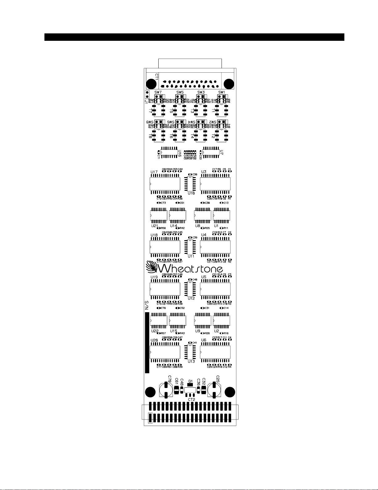
SCHEMATIC DRAWINGS
ADR-32 / Dec 2002
8 Digital Inputs Card (SRC-8) - Load Sheet
page 5 – 4
page 5 – 10
Page 78
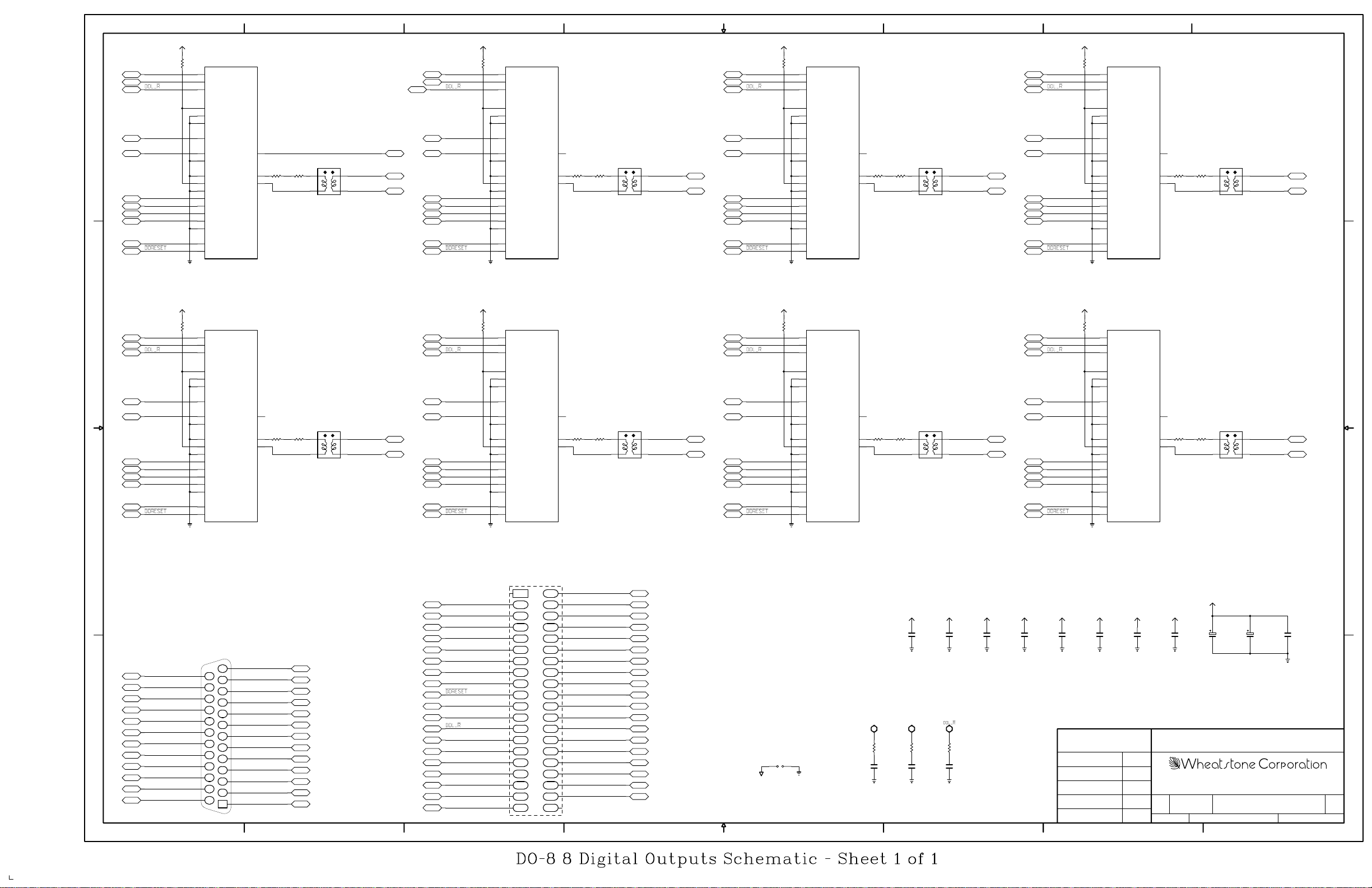
D
8
DOSDATA1
DOSCLK
DO_V
DO_C
DO_C6
DO_C7
DO_EM1
DO_EM0
DOMCLK
VCC
R12
1.00K
GND
8
SDATA
6
SCK
7
FSYNC
21
M0
22
M1
23
M2
9
V
10
C/SBF
11
U
____
2
PRO
___
3
C1/FCO
24
TRNPT/FC1
_____
4
C6/C2
_____
1
C7/C3
13
EM1/C8
14
EM0/C9
______
12
C9/C15
5
MCK
____
16
RST
U4
___
___
CS8402A
CBL/SBC
TXN
TXP
7
DOSDATA2
DOSCLK
DO_V
15
R351 R151 R451 R251
17
20
T1
6
DO_CBL
LINE1_D_HI
34
LINE1_D_LO
1
DO_C
DO_C6
DO_C7
DO_EM1
DO_EM0
DOMCLK
VCC
6
R11
1.00K
GND
8
SDATA
6
SCK
7
FSYNC
21
M0
22
M1
23
M2
9
V
10
C/SBF
11
U
____
2
PRO
___
3
C1/FCO
24
TRNPT/FC1
_____
4
C6/C2
_____
1
C7/C3
13
EM1/C8
14
EM0/C9
______
12
C9/C15
5
MCK
____
16
RST
U3
___
___
CS8402A
CBL/SBC
TXN
TXP
LINE4_D_HI
3
LINE4_D_LO
1
1
D
GND
8
SDATA
6
SCK
7
FSYNC
21
M0
22
M1
23
M2
9
V
10
C/SBF
11
U
____
2
PRO
___
3
C1/FCO
24
TRNPT/FC1
_____
4
C6/C2
_____
1
C7/C3
13
EM1/C8
14
EM0/C9
______
12
C9/C15
5
MCK
____
16
RST
2
U1
___
___
CS8402A
CBL/SBC
TXN
TXP
15
17
20
T4
4
6
3
VCC
R9
DOSDATA4
DOSCLK
DO_V
DO_C
T3
LINE3_D_HI
LINE3_D_LO
1
DO_C6
DO_C7
DO_EM1
DO_EM0
DOMCLK
1.00K
VCC
R10
1.00K
GND
4
8
SDATA
6
SCK
7
FSYNC
21
M0
22
M1
23
M2
9
V
10
C/SBF
11
U
____
2
PRO
___
3
C1/FCO
24
TRNPT/FC1
_____
4
C6/C2
_____
1
C7/C3
13
EM1/C8
14
EM0/C9
______
12
C9/C15
5
MCK
____
16
RST
U2
___
___
CS8402A
CBL/SBC
TXN
TXP
15
R751 R551 R851 R651
17
20
43
6
5
DOSDATA3
DOSCLK
DO_V
15
T2
17
20
43
6
LINE2_D_HI
LINE2_D_LO
1
DO_C
DO_C6
DO_C7
DO_EM1
DO_EM0
DOMCLK
C
B
A
UDB25
UDB24
UDB23
UDB22
UDB21
UDB20
UDB19
UDB18
UDB17
UDB16
UDB15
UDB14
VCC
R13
DOSDATA5
DOSCLK
DO_V
DO_C
DO_C6
DO_C7
DO_EM1
DO_EM0
DOMCLK
1.00K
GND
8
6
7
21
22
23
9
10
11
2
3
24
4
1
13
14
12
5
16
DB-25 CONNECTOR
AGND
LINE1_D_HI
LINE2_D_LO
AGND
LINE3_D_HI
LINE4_D_LO
AGND
LINE5_D_HI
LINE6_D_LO
AGND
LINE7_D_HI
LINE8_D_LO
8
SDATA
SCK
FSYNC
M0
M1
M2
V
C/SBF
U
____
PRO
___
C1/FCO
TRNPT/FC1
_____
C6/C2
_____
C7/C3
___
EM1/C8
___
EM0/C9
______
C9/C15
MCK
____
RST
CS8402A
CT1
13
25
12
24
11
23
10
22
9
21
8
20
7
19
6
18
5
17
4
16
3
15
2
14
1
U5
CBL/SBC
VCC
R14
DOSDATA6
DOSCLK
DO_V
15
R1951 R1751 R2051 R1851
17
TXN
20
TXP
T5
43
6
LINE5_D_HI
LINE5_D_LO
1
DO_C
DO_C6
DO_C7
DO_EM1
DO_EM0
DOMCLK
GND
GND
V+
VGND
AGND
LINE1_D_LO
AGND
LINE2_D_HI
LINE3_D_LO
AGND
LINE4_D_HI
LINE5_D_LO
AGND
LINE6_D_HI
LINE7_D_LO
AGND
LINE8_D_HI
UDB13
UDB12
UDB11
UDB10
UDB9
UDB8
UDB7
UDB6
UDB5
UDB4
UDB3
UDB2
UDB1
GND
VCC
GND
DOMCLK
DOSCLK
DO_CBL
ID_DIG
GND
DOSDATA4
DOSDATA3
DOSDATA2
DOSDATA1
7
1.00K
GND
ID=DIGITAL
6
8
SDATA
6
SCK
7
FSYNC
21
M0
22
M1
23
M2
9
V
10
C/SBF
11
U
____
2
PRO
___
3
C1/FCO
24
TRNPT/FC1
_____
4
C6/C2
_____
1
C7/C3
___
13
EM1/C8
___
14
EM0/C9
______
12
C9/C15
5
MCK
____
16
RST
CS8402A
1
3
56
78
9
11 12
13 14
15 16
17 18
19
21 22
23 24
25 26
27 28
29
31 32
33 34
35 36
37 38
39
U6
CBL/SBC
CT2
TXN
TXP
VCC
R15
DOSDATA7
DOSCLK
1.00K
DO_V
15
T6
17
20
4
6
LINE6_D_HI
3
LINE6_D_LO
1
DO_C
DO_C6
DO_C7
DO_EM1
DO_EM0
DOMCLK
GND
2
4
DOSDATA5
DOSDATA6
DOSDATA7
DOSDATA8
10
GND
DO_V
DO_C
8
SDATA
6
SCK
7
FSYNC
21
M0
22
M1
23
M2
9
V
10
C/SBF
11
U
____
2
PRO
___
3
C1/FCO
24
TRNPT/FC1
_____
4
C6/C2
_____
1
C7/C3
13
EM1/C8
14
EM0/C9
______
12
C9/C15
5
MCK
____
16
RST
U7
___
___
CS8402A
CBL/SBC
TXN
TXP
DOSDATA8
DOSCLK
DO_V
15
R2651 R2351 R2751 R2451
17
20
T7 T8
LINE7_D_HI
34
LINE7_D_LO
1
6
DO_C
DO_C6
DO_C7
DO_EM1
DO_EM0
DOMCLK
VCC
GND
C11
0.1uF
VCC
GND
C8
0.1uF
VCC
GND
C9
0.1uF
VCC
GND
C7
0.1uF
DO_C6
VCC
GND
C5
0.1uF
VCC
R16
1.00K
GND
VCC
GND
8
SDATA
6
SCK
7
FSYNC
21
M0
22
M1
23
M2
9
V
10
C/SBF
11
U
____
2
PRO
___
3
C1/FCO
24
TRNPT/FC1
_____
4
C6/C2
_____
1
C7/C3
13
EM1/C8
14
EM0/C9
______
12
C9/C15
5
MCK
____
16
RST
C10
0.1uF
U8
___
___
CS8402A
CBL/SBC
VCC
C6
0.1uF
GND
TXN
TXP
C
15
17
20
4
6
LINE8_D_HI
3
LINE8_D_LO
1
B
VCC
VCC
GND
C3
0.1uF
GND
C4
0.1uF
C1
100uF
C2
1uF
DO_C7
20
30
40
DO_EM1
DO_EM0
GND
VCC
GND
GND
GND
GND
DOMCLK
V-
V+
5
AGND
J1
GND
4
GND
DOSCLK
R21
150
C12
33pF
GND
R22
150
C13
33pF
GND
R25
150
C14
33pF
3
CONTRACT NO.
- Sergey Averin -
DRAWN
CHECKED
W# 700735
DO-8
A
DATEAPPROVALS
SA
5-22-03
2
SA
SA
D
600 Industrial Drive
New Bern, NC 28562
DWG. NO.FSCM NO.ISSUED
14S00xx
DO-8A PCB
REVSIZE
SHEETSCALE
A
1 OF 1
1
ADR-32/May 2003
page 5 - 11
Page 79
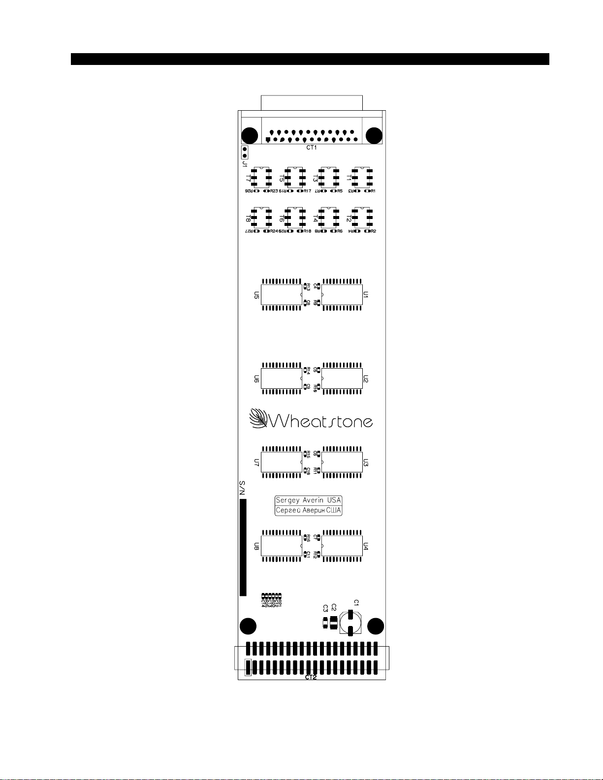
SCHEMATIC DRAWINGS
ADR-32 / Dec 2002
8 Digital Outputs Card (DO-8) - Load Sheet
page 5 – 5
page 5 – 12
Page 80
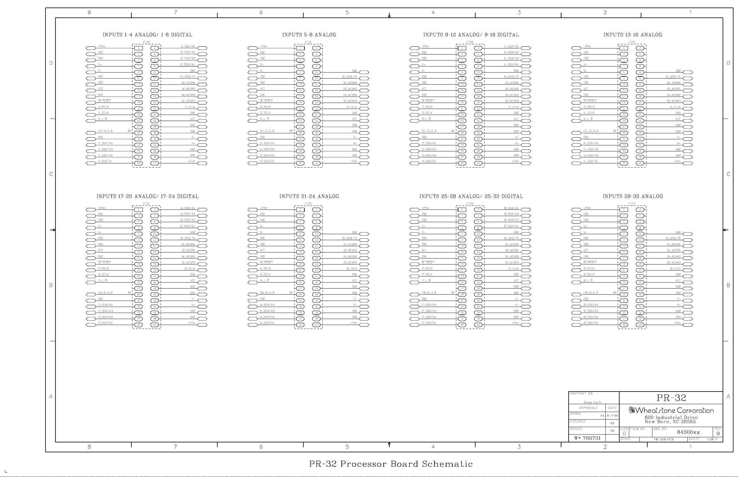
ADR-32/Jun 2003
page 5 - 13
Page 81
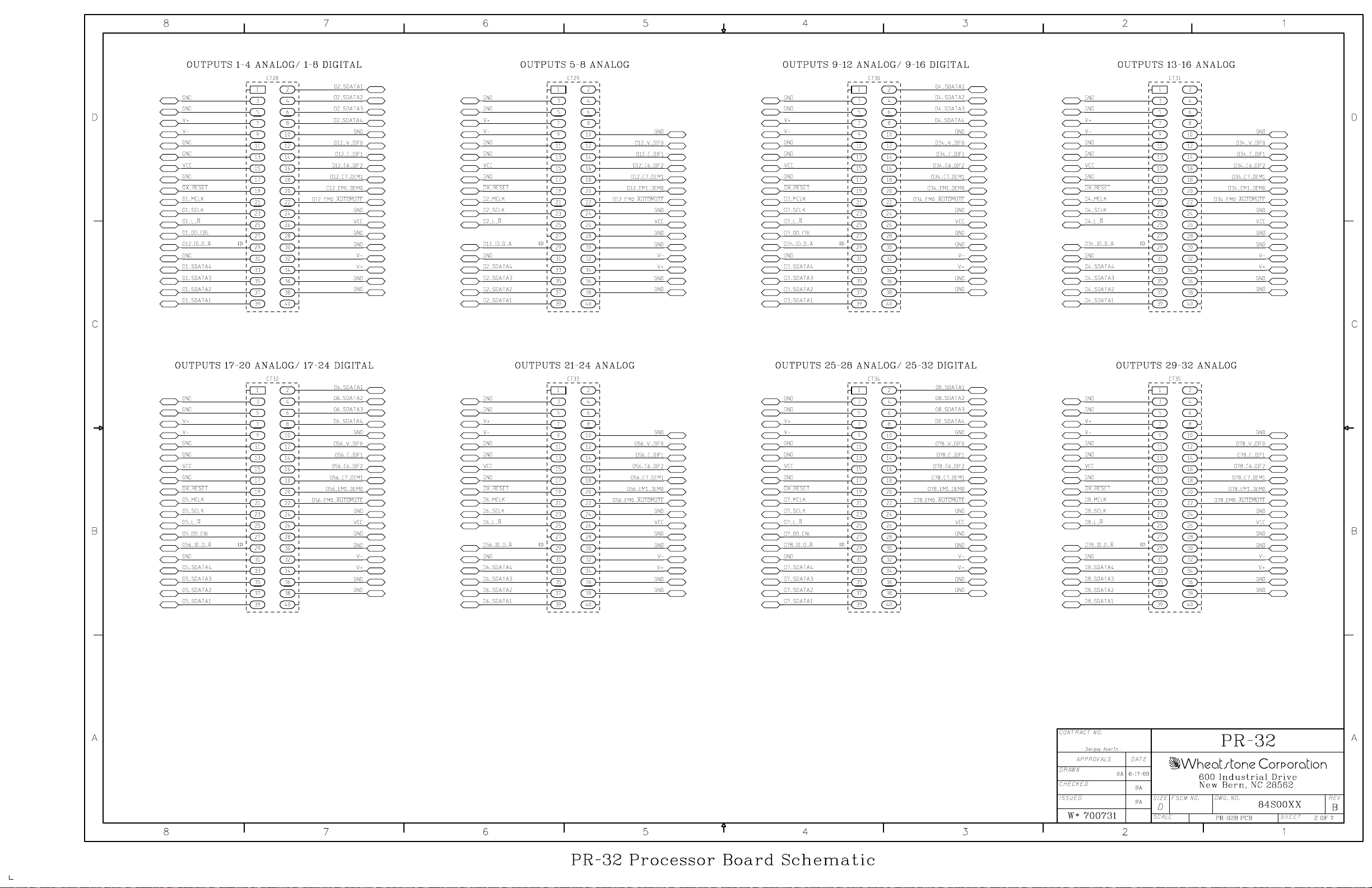
ADR-32/Jun 2003
page 5 - 14
Page 82
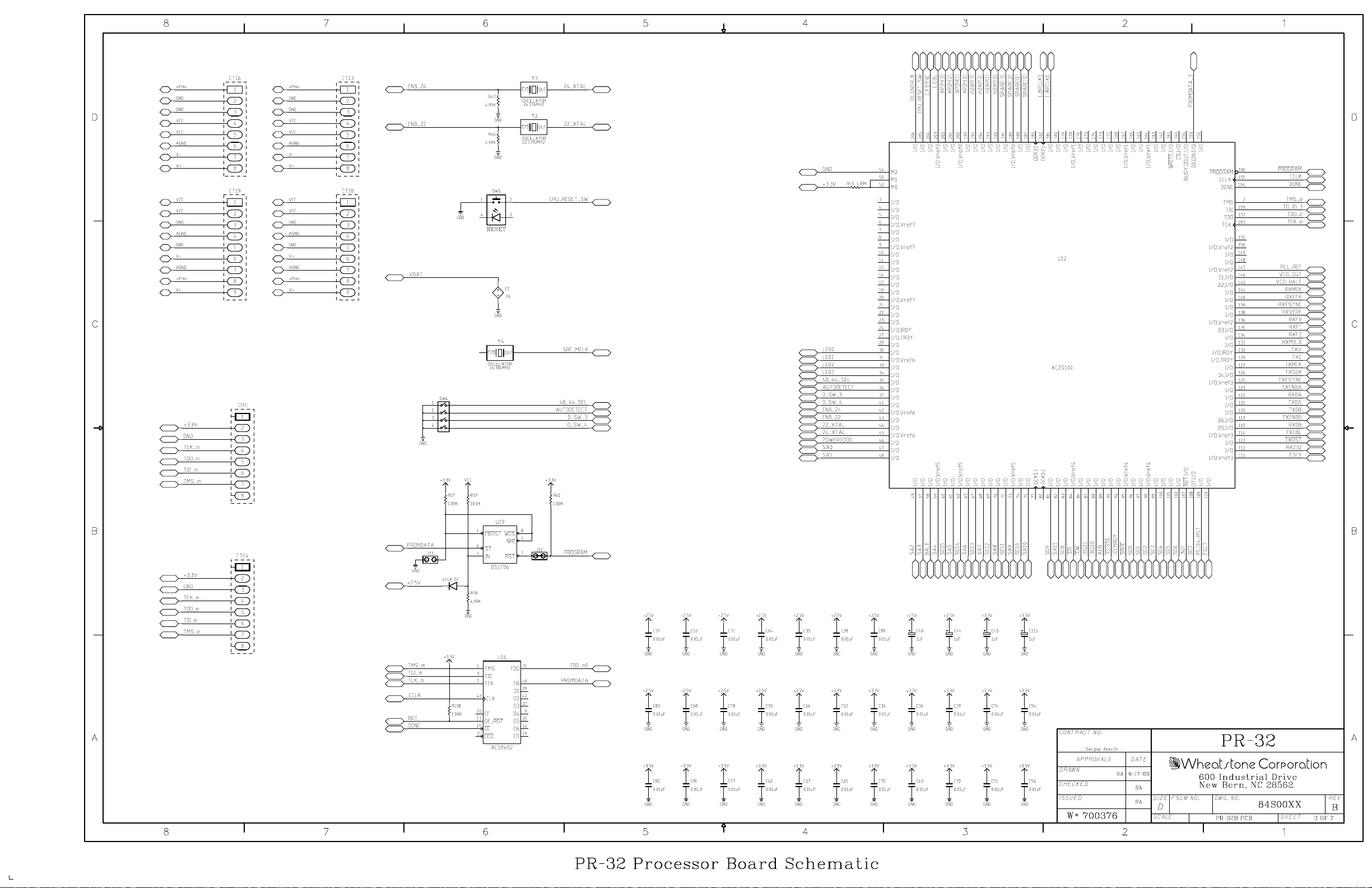
ADR-32/Jun 2003
page 5 - 15
Page 83
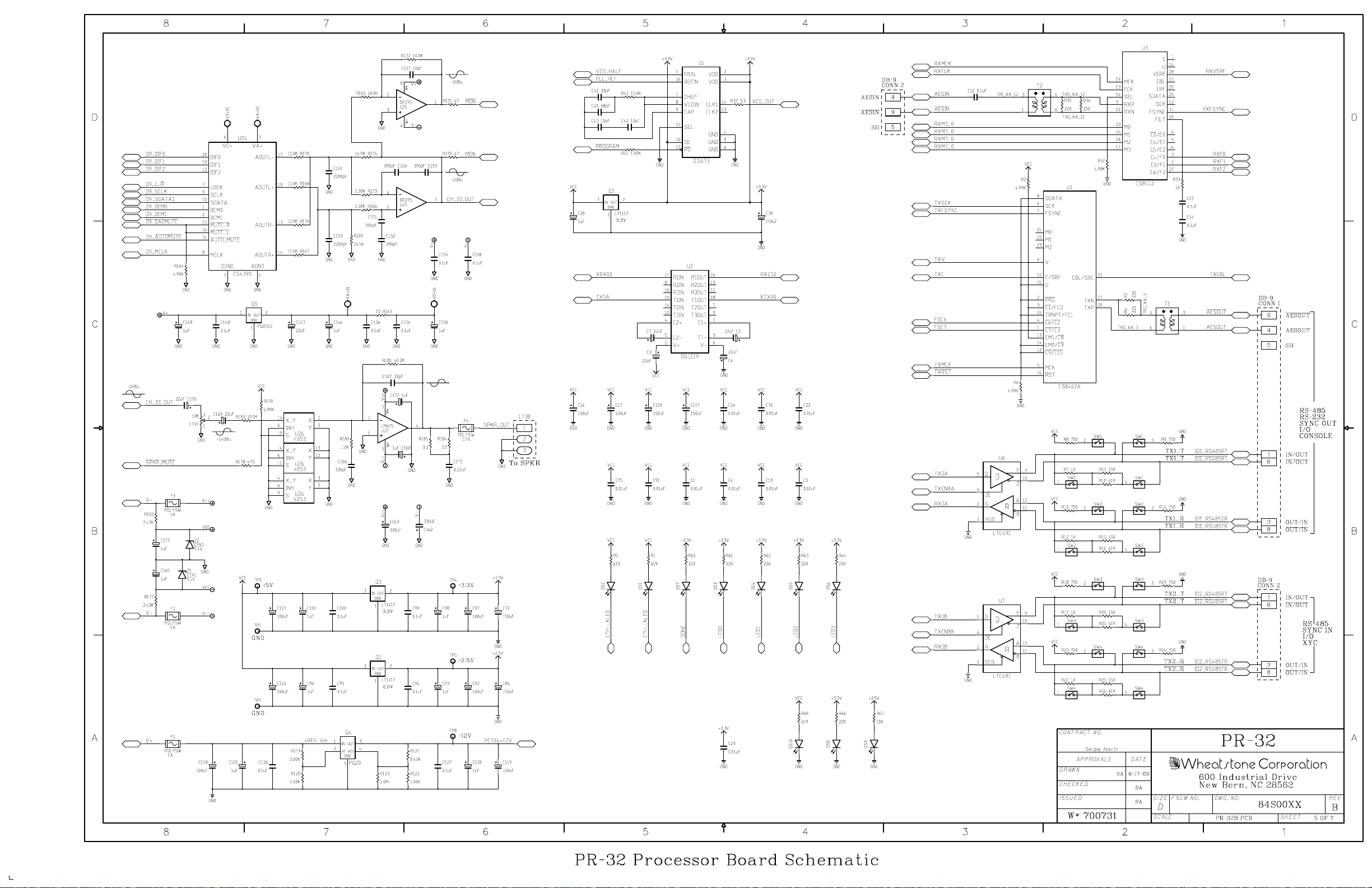
ADR-32/Jun 2003
page 5 - 16
Page 84
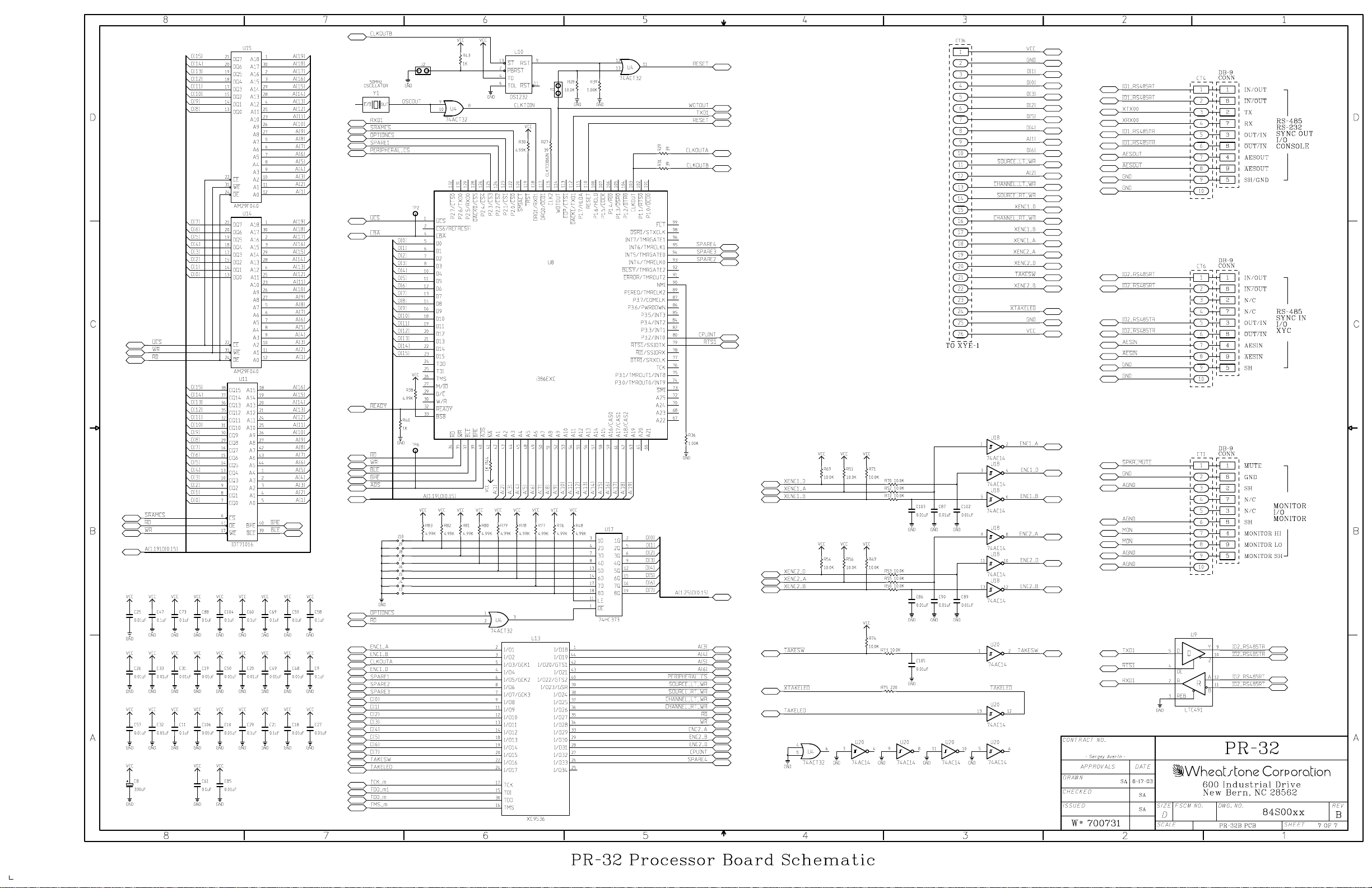
ADR-32/Jun 2003
page 5 - 17
Page 85
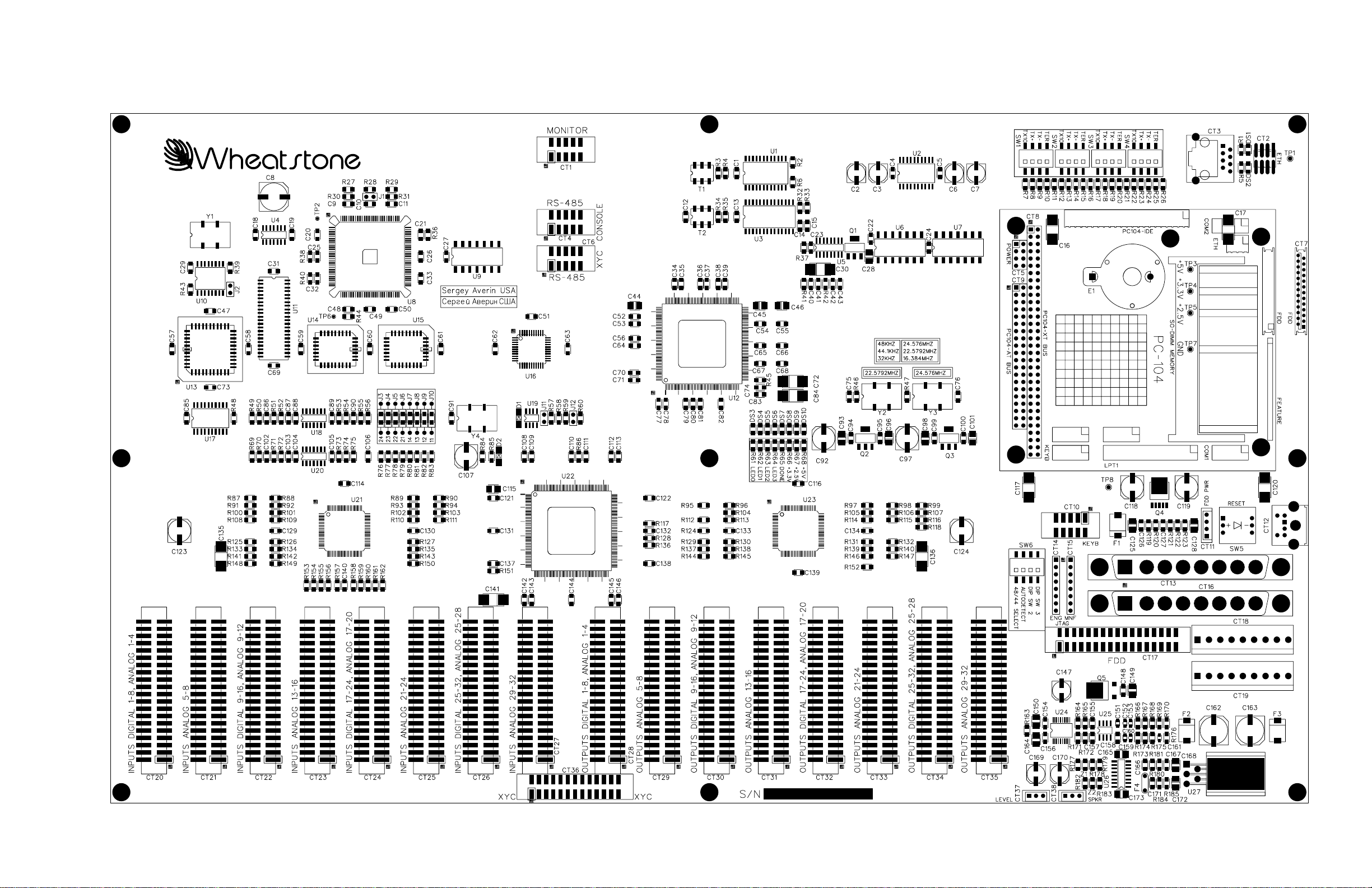
ADR-32 / Jun 2003
Processor Board (PR-32) - Load Sheet
page 5 – 18
Page 86

GLOSSARY
Glossary
The terminology used in this manual is defined as follows:
• Channel - A single,
to 64 discrete inputs to 64 discrete outputs (32 x 32 stereo) per tier.
• Signal - Information from a single audio source. A signal may take up one
(mono), two (stereo), or six (5.1 surround sound) channels.
• Chassis or Rack - A single ADR-32 backplane.
• GUI (pronounced “goo-eee”) - refers to the Windows X-Point program
Graphical User Interface.
• XYC GUI - refers to the X-Point program running in XY controller mode.
• Slot - A position within a rack where a single card is located.
• Tier - The ADR-32 is based on advanced X-Point software that supports
multiple hardware levels called Tiers. While the software supports
multiple tiers, the ADR-32 hardware only supports one tier.
• Salvo - A logical grouping of connections that may be made by the
operator via a single action (on the Configuration GUI, XYC GUI, or XY
Controller).
monaural audio stream. The ADR-32 can switch up
The following terms apply to router configuration:
• Switch ID - A unique identifier assigned to each ADR-32 router.
• Rack ID - The physical chassis ID number.
• Slot ID - The physical slot number (numbered from 1-16).
• Channel ID - Channel IDs run from 0-64. Input Channel IDs are assigned
directly to the input devices. Output Channel IDs are assigned directly to
the output devices.
• Signal Type - Each input and output in the ADR-32 is associated with a
type of signal. These include mono, stereo, or surround sound. The
importance of this information at configuration time is the number of
channels each signal consumes. Mono signals use 1 channel; stereo
signals use 2; and surround sound signal use 6.
ADR-32 / Dec 2002
page G – 1
Page 87

APPENDICES
Appendices
Appendix 1
Configuring the ADR-32 Network Parameters........................... A-3
Appendix 2
Replacement Parts List ............................................................... A-6
ADR-32 / Dec 2002
page A – 1
Page 88

APPENDICES
Appendix 1
Contents
Configuring the ADR-32 Router Network Parameters .............. A-3
ADR-32 / Dec 2002
page A – 2
Page 89

APPENDICES
Configuring the ADR-32
Router Network Parameters
Caution! Your system has been preconfigured at the factory for a default
IP address of192.168.1.160. Incorrect use of this utility program can cause
system malfunction. Check the IP address label on the top cover of the ADR32 before making changes. Please consult Wheatstone support if you are
having trouble connecting your system to a network or PC.
In order to communicate to the ADR-32 Router, appropriate network
parameters must be loaded. Since the GUI cannot communicate with the
router until these parameters are set, a special method for configuring the
router is necessary.
There are several constraints on the router configuration that were made
to simplify the installation, while still providing the flexibility to connect the
router to existing customer networks. Here are the list of constraints:
1. The router and any attached GUIs must exist on the same subnet. The
router has no ability to route across subnets.
2. If dynamic address allocation is used on the network (e.g. DHCP), the
router must be given a “permanent” address allocation. In order to allow the
router to run on simple networks or at sites with little system admin support,
dynamic address allocation schemes (such as DHCP or BOOTP) were not
used to provide an IP address to the router.
The following steps are required to provide the necessary configuration
info to the router (this only has to be done one time):
1. From any DOS or Windows PC on the same subnet that the router will
be on (in other words, with no routers between the PC and ADR-32), run the
AdvXP_Network_Config.exe program.
2. The first prompt is: *Default Values
Enter Number of Tiers [1].................: 1
Enter “1” for the total number of tiers in the system (ADR-32 is always 1 Tier).
3. Enter Tier #1 address [192.168.0.160].....: 192.168.1.160
Enter the IP address reserved for the router on your network. This address must
be unique within the network.
4. Enter Tier #1 TCP Port [50012]............: 50012
This is the TCP port number to use for the command connection. It can be
changed in the rare circumstance that it conflicts with another port in use on
the GUI PC. The default can almost always be used.
ADR-32 / Dec 2002
ADR-32 / Jun 2003
page A – 3
Page 90

APPENDICES
5. Enter Network Mask [0xFFFFFF00]...........: FFFFFF00
0xFFFFFF00 = hexadecimal FFFFFF00 = 255.255.255.0 dotted decimal
Note: Do NOT enter the 0x base identifier.
Enter the network mask for your subnet in hexadecimal format. See your
system administrator if you’re unsure of the proper value. The default will work
for most simple, localized networks.
6. Enter GUI IP address [192.168.0.212]......: 192.168.1.212
Enter the IP address of the GUI PC used to communicate to the router. This
address must be on the same subnet as the router. Once configured, it is not
necessary to change this value if you run the GUI on a different machine.
7. Enter XYC GUI UDP Port [55555]............: 55555
This is the UDP port number used to broadcast configuration and receive
connections from XYC GUIs. It can be changed in the rare circumstance that it
conflicts with another port in use on the GUI PC. The default can almost always
be used.
8. The program then displays the following prompt:
About to configure Tier #1...
1. Make sure this is the only tier currently connected to
the local network!
2. Press <RETURN> when ready to proceed...
The configuration parameters for the ADR-32 are now UDP broadcast, and
should be received by the router (make sure only the appropriate tier is connected
to the network; turn off the power or disconnect the Ethernet cable on any other
routers). If a debug terminal is attached to the router, a confirmation message is
printed.
9. Reboot the ADR-32 - power it down and then power it back up. The new
network parameters now should be in effect.
ADR-32 / Dec 2002
ADR-32 / Jun 2003
page A – 4
Page 91

APPENDICES
Appendix 2
Contents
Replacement Parts List ............................................................... A-6
For the most part there are no user-replaceable parts in the
ADR-32 Router. A complete list of available components is shown on
the next page. Contact Wheatstone technical support for further information.
Wheatstone Corporation (600 Industrial Drive, New Bern, North Carolina,
USA 28562) may be reached by phone at 252-638-7000, fax 252-637-1285,
electronic mail “[email protected]”.
ADR-32 / Dec 2002
page A – 5
Page 92
A P P E N D I C E S
COMPONENT
DESCRIPTION
WS P/N
REPLACEMENT PARTS — ADR-32 ROUTER
SRC-8 DIGITAL INPUT CARD "008454"
ADC-4 ANALOG INPUT CARD "008455"
DO-8 DIGITAL OUTPUT CARD "008456"
AO-4 ANALOG OUTPUT CARD "008457"
PR-32 CARD MAIN PROCESSOR LOADED CARD "008453"
XYE-1 XY CONTROLLER LOADED CARD "008452"
CONNECTOR KIT CONNECTOR KIT FOR ADR-32 "008478"
POWER CORD 7 1/2' BLACK POWER CORD "150017"
CABLE CAT-5 SOLID CONDUCTOR CABLE "150189"
DB9 I/O CONNECTOR 9 PIN DB CONNECTOR "200031"
PLUG FOR DB25 I/O CONNECTOR PLUG FOR DB25 CONNECTOR "200100"
PIN FOR I/O CONNECTOR MALE PIN FOR DB25 PLUG "200101"
HOOD FOR DB25 PLUG METALIZED PLASTIC STRAIGHT HOOD FOR DB25 PLUG "200102"
PLUG FOR DB9 I/O CONNECTOR PLUG FOR DB9 CONNECTOR "200109"
HOOD FOR DB9 PLUG METALIZED PLASTIC STRAIGHT HOOD FOR DB9 PLUG "200124"
RIBBON PLUG 10 PIN RIBBON PLUG "230020"
PLUG 3 PIN PLUG "230028"
RIBBON PLUG 26 PIN RIBBON PLUG "250043"
HEADER 3 PIN HEADER "250062"
CONNECTOR MALE RJ-45 CONNECTOR "260052"
COUPLER RJ-45 COUPLER "260055"
SPEAKER POT 10KΩ SINGLE AUDIO CONDUCTIVE POT "500058"
SOURCE/DESTINATION KNOB 29MM GREY KNOB "520059"
SPEAKER KNOB 21MM GRAY SIFAM COLLET KNOB "520108"
SPEAKER CAP GRAY CAP W/BLACK LINE "530035"
SOURCE/DESTINATION CAP BLACK CAP "530318"
CONNECTOR CUTOUT COVERS DB25 CONNECTOR CUTOUT COVERS "824012"
CONNECTOR CUTOUT COVERS DB37 CONNECTOR CUTOUT COVERS "824037"
FAN GUARD FAN GUARD "840018"
FAN 60MM SQUARE 5V DC FAN "840020"
CRIMP TOOL CRIMP TOOL FOR DB CONNECTOR "850068"
TOOL EXTRACTOR PIN EXTRACTOR TOOL FOR DB CONNECTOR "850069"
REPLACEMENTSPEAKER CUE SPEAKER "960012"
MANUAL OWNER'S MANUAL "008479"
X-POINT SOFTWARE X-POINT SOFTWARE CD FOR ADR-32 "071794"
ADR-32 / Dec 2002
page A – 6
 Loading...