

Page 1

AUDIO ANALOGUE
multi-channel audio/video processor
MANUAL
Version 0.0 - 10/03
Page 2
Page 3

INTRODUCTION
AUDIO ANALOGUE does not take any responsibilities in the following cases:
Whenever the operational procedures related to the use and the maintenance of the equipment as described in this manual
are not respected.
Whenever damages to the equipment occur because of fixing and modifications made form non-authorized staff or because
of normal deterioration of the system.
No part of this manual can be reproduced by any means, transmitted or copied for private or public use without private
authorization from AUDIO ANALOGUE.
The information contained in this manual is related to the data kept by AUDIO ANALOGUE at the moment of the issue
o f this publication; AUDIO ANALOGUE has the right to make changes to this document without prior notice.
The equipment has been projected and manufactured according to the Regulations of the Community 89/336/CEE and
is marked CE.
This equipment can’t be used for different purposes other than those for which it has been manufactured.
AUDIO ANALOGUE does not take any responsibilities for accidents or damages due to improper use of the equipment.
WARNING
Please do respect the safety standards contained in this manual before starting to operate the equipment.
Do not open the equipment. No further interventions than those described in this manual should be made. For technical
assistance, please consult a qualified technician or an AUDIO ANALOGUE dealer.
Not respecting the instructions contained in this manual will invalidate the terms and conditions of the guarantee.
NECESSARY PRECAUTIONS FOR SAFETY AND MAINTENANCE
ATTENTION: before starting any operation, use or maintenance of the equipment it is strictly necessary to understand
the following manual.
To avoid any accidents or hazards it is necessary to follow the following regulations.
Activate the equipment only prior checking if the installation has been properly made, and if it is related to the instructions
contained in this manual.
Avoid installing the equipment in plac e s s u b j e c t e d to extreme l y hi g h t e m p e r a t ures or humi d i t y.
Check that the labels containing inf ormation about safety are always visible and in good conditions.
Ensure to not obstruct ventilation, to avoid excessive overheating. The equipment should be kept to a minimal distance
of 15 cm from any object and not to place on carpet or other soft surfaces. Also the installation close to radiators or in
close environments without ventilation should be avoided.
Do not switch on the equipment until it has not been correctly and completely installed.
Only supply the equipment with the kind of the electric supply as stated on the appropriate label. If in doubts about the
kind of supply available, please consult an expert technician for technical assistance.
The equipment needs to be wired to an earth terminal. The external case is metal made; a defective connection with the
earth may be dangerous.
In case damages occurs to the supply cable, it should be immediately replaced with the same kind of cable. This operation
should be only made prior to disconnecting the main supply.
Do not place objects on the supply cable and check that this is not positioned in way through. The cable should not be
knotted or curly.
Replace the fuses always with other of the same kind.
Do not use the equipment close to the water or other liquids. If liquid entered the equipment, the plug should be disconnected
from the socket avoiding to touch the metal parts. Competent technical staff should be asked to check the equipment
before operating it again.
Do not place recipients containing liquids on the equipment. Even when it is switched off.
Keep the equipm e n t f a r fro m s o u r c es of h e a t s u ch as t h e s o l a r li g h t , k i tch e n s , r a dia t o r s etc…
Always unplug the supply cable during rainy weather.
Always Switch off and unplug the supply cable before cleaning the equipment externally.: this operation should be made
using a dry and soft cloth. Never use alcohol based cleaning material.
If the amplifier was carried from an extremely cold environment to and extremely hot one, it could create internal
condensation, causing possible bad functioning.
If this occurs, please wait for at least an hour before using it again, to allow it to gradually reach room temperature.
When not used for long periods, please unplug the equipment.
INSTRUCTIONS TO PUT IT OUT OF SERVICE
Consult qualified staff
Follow the regulations of the current legislation regarding recycling and waste disposal.
I
3
Page 4

Dear Audiophile
Congratulations for choosing the multi-channel audio/video processor CINECITTA’. You purchased an audio component
highly musical and highly accurate, able of an extraordinary performance in any home theater system.
Its refined circuit gives great purity of sound whilst its innate elegance will ensure an easy integration in every environment
and with the rest of the system.
To obtain the best from your new amplifier, we advice to use only components and cables of the highest quality; follow
our advice and the multi-channel audio video processor will give you years of musical pleasure.
Please take some of your time to read this manual before installing your new processor.
We hope you enjoy your experience with Audio Analogue sound!
For your future guidance, we advice you to take a note of the registration number, printed on the rear panel of the amplifier.
The date of purchase and the name of the dealer in the space below.
Registration Number:
Date of purchase
Name of the Dealer.
4
Page 5

it is the city of the cinema, founded in 1937, 140.000
squared meters extended, it includes studios, building which have been the location
of va r ious movies, sw i mming pools and sp a ces for extern a l sh ooting.
is a city set in the magical atmosphere of Rome, it is the
place of the dreams of Fellini, of the wonderful and daily dramas of Rossellini. Of the
refined talent of Visconti, of the sad tale of De Sica., of the glances of Magnani, of
the smiles of Mastroianni and of the lips of Loren., and also more recently of the blood
bath of Scorsese in Gangs of New York and of the dirty businesses of the Godfather
from Coppola.
is the Italian symbol in the history of the cinema in the world,
and for anybody who has watched a work of art shot over there is the symbol of the
emotion.
AUDIO ANALOGUE has entitled in this way its Audio/Video reference frame to pay
homage to the cinema and to declare so its ambitions: creating the landmark for the
domestic production of movies, manufacturing objects putting together high technology,
emotion and the elegance of the great cinema.
Ladies and gentleman, please enjoy the show!
A dream called
5
Page 6

Page 7

AUDIO ANALOGUE
MANUAL
8 Features of construction
9 Description of the front panel
10 Description of the rear panel
11 Description of the remote control
12 Opening and inspection of the package
13 Connecting the
processor
14 BASIC FUNCTIONAL OPERATIONS
Switching the
Processor
Regulating the volume and mute
15Sel ection of the audio input, for the listen ing
Examples to use the inputs
16 Notes about operating the audio input
Selection of the input for the analogue recording
Selection of the input for the digital recording
Notes regarding the recording video bar
Selection of the decoding bar
17 Stand-by
Brilliance of display
Automatic memor i z a t i o n of the fu n c t i o nin g
condition
18 Remote control
19Co n f i g u r a t i o n of the
Processor
Set up activation
Set up navigation
Slip of the menu functions
Sel e ct ion of the me n u en h an ce d fu nc ti on
Modification of the value of the numerical parameter
Exit from a menu
Emergency exit from the set up
20 SET-UP MAIN MENU CONFIGURATION
21 AUDIO
22 VIDEO
23 TRIGGER
24 TIMER
25 WATCH
26 LANGUAGE
27 REMOTE CONTROL
28 SPEAKERS
29 LEVELS
30 DELAYS
31 SUB FREQUENCY CUT
32 DOLBY
33 DTS
34 PHONO GAIN
35 VIDEO
OUTPUTS
36 SYNCRONISMS
37 VIDEO CONNECTIONS
38 VIDEO DIRECT RECORDING
39 OUTPUT PROGRAMMATION MODE
40 OUTPUT COMP. MODE
41 STANDARD
42 TRIGGER CONNECTIONS
43 SWITCHING OFF
44 TIMER SET UP
45 WATCH SET UP
46 REMOTE CONTROL
BASIC CODE PROGRAMMATION
47 IR CODE
48 TECHNICAL SPECIFICATIONS
7
page
Page 8

Dear Audiophile,
Congratulations and thank you for choosing the Cinecitta’ multi-channel Audio Video
Processor. Now you own the equipment which establishes the new landmark in that
narrow category of audio/video products which put together the quality, the versatility
and completeness of the high-end products. The Cinecitta’ Processor associates circuit
solutions without compromising functional features to satisfy even the most fussy
user. Circuits with discrete components and high performance, functional sections on
removable and updateable cards, total configuration, interfacciabilita’ with the PC or
home automation equipments: solutions which make the Cinecitta’ Processor a profitable
investment.
Construction Features
Analogue circuits with discrete components, wide bar and low counter reaction
Phono amplifier MM/MC and tape bar buffer with integrated circuits and high
performance.
Very high quality passive components: low or very low tolerance metal resistors,
polyester or polypropylene low tolerance non polarized capacitors, high capacity with
low loss electrolytic condensers, low capacity with organic electrolyte electrolytic
condensers.
Volumes regulators with integrated resistors web without buffer for maximum
transparency of sound.
Relay of commutation with gold plated silver contacts. No capacitors on the way of
the signal.
Circuit to recover the offset.
Analogue supply with toroidal transformer, two different supply lines and 5 independent
regulation phases.
Decoding digital card for the replaceable audio multi-channel. Compatibility with
Dolby Digital EX, Dolby Pro-Logic II, DTS-ES-Neo:6. A rewriting memory includes
the decoding algorithms: it is so possible to update the purchased algorithms or to add
some new on e s i f ava i l a b le t h r o ugh t h e i nt e r f a ce R S - 2 3 2 i n c l u ded .
Converters D/A with 8 channels,192kHz/24bit. Converters A/D stereo 192Khz/24bit.
Reference clock with low jitter.
Replaceable I/O audio digital card. Electric 192KHz/24bit coaxial inputs, Toslink
96kHZ/24bit optical inputs. Tape output with separated bar. It is possible to transfer on
the digital tape bar even the analogue channel selected for listening prior to A/D
conversion.
Digital supply with 8 independent regulation phases.
Replaceable video card. Channels. Composite, S-Video and component. Exits:
composite, S-Video, Component YcbCr or RGB con configuration synchronism, on
3x RCA connector or Dsub-15. Four formats are available contemporarily, thanks to
a cross-conversion digital matrix. It is possible to deactivate the non-used exits to
minimize the noise of the video.
Vid e o co mmutation wit h so lid condition swi t ch with very wide b a n d.
Very high-speed exit buffer. Counter –images filters with discrete components with
very high gradient, for an optimal connection with digital display. Available synchronisms
on RCA connectors in various ways.
Triple A/D, 12bit/54MHz converter. Six, 10bit/54MHz, D/A converters connected
outputs, triple D/ A , 11 bit/54MH z c o n v e r t ers fo r t h e p r o g r essi v e o u t p u ts.
Separate tape bar with composite exits and S-Video. It is also possible to send to the
tape output signals bound to the monitor exits; in this way it will be possible to obtain
a format conversion. It is so possible, for instance, to record composite source or
component on a record player equipped only with S-Video exit.
Deinterlacing PAL and NTSC circuit with Faroudja DCDi algorithms.
On-screen Display external to the conduct for the video signal to preserve best quality
of image.
Reference clock with low jitter
Video supply with 7 independent regulation phases.
Organizing system with multiple concurrent control.: from front panel, from remote
control and from interface RS-232.
Organizing system with a net of micro checkers, 16bit master checker. Organizing
software of the equipment updateable with. PC.
Selection able Remote control group code to avoid further interferences with remote
controls from other equipments. Automatic teaching remote control system to program
learning remote controls directly from the processor or for reprogramming the
supplied remote control in case of battery decay.
Very wide frontal display with complete set-up for the equipment configuration when
the Tv display or the monitor is missing. High-resolution encoder for the selectors.
Four levels regulating display brilliance.
Organizing system, configuration and updating of the decoding algorithms of the
supplied software in Windows.
8
Page 9

Front panel description
1 .Multifunctional Selector ‘ Select’. It allows selecting: The source to be listened
(analogue or digital), the analogue source to be sent on the analogue tape output,
the digital source to send on the digital output tape. Besides, it allows to test the
different menu’s functions and to modify some of set-up parameters.
2 Volume check. It allows selecting the general level of listening. It also allows
to modify some of th e set - u p param e t e r s whe n this is active.
3 Button ‘ Analogue Tape’. When this button is pressed, it is able to select the
analogue tape bar. The signal of the available source on the analogue tape
output appears on the display. Releasing the button, the exit selector starts again
its standard function and the signal on the display disappears. This button is
also used to select the set- up options.
4 Button ‘Digital Tape’. When this button is pressed, the outputs selector assumes
the function of selection the digital tape bar. The signal of the available source
on the digital tape exit appears on the display. Releasing the button, the output
selector starts again its standard function and the signal on the display
disappears.
5 Set up activation. Press contemporarily the buttons; ‘Analog Tape’ and ‘Digital
Tape’ to recall the set-Up.
6 Button’ Mute’. It activates and deactivates the audio signal muting. When the
mu t i n g is acti v e the volume is reduced to backgroun d s leve l .
7 Button ‘Mode’. It allows to choose in sequence the ways of decoding multi-
channel available for the selected channel. The range of possible decoding
ways is automatically determined from the processor.
8 Display. It shows the functioning conditions of the processor, or the options
from the set-up. When the Cinecitta’ Processor is in stand-by it shows the
time.
9 Receiver IR.
10 Emitter IR. It is used to teach the IR codes to a learning remote control.
11 Indicators of the different ways of programming. It lights up red when the
processor has activated the function of transferring of the organizing software
from PC through the serial port.
9
select
volume
analog
tape
digital
tape
mode
mute
multi-channel
audio/video processor
1 2
3
4
5
7
6
8 9
10
11
Page 10

Rear panel description
1 So cket accordi n g IEC regulat ions. It conn ect the supply cable.
2 Fuses. In case of necessity they should only be replaced with the same kind
of fuses.
3 Trigger Output
4 RS-232 Serial port
5 Phono Channel MM/MC
6 Earth terminal
7 Audio Stereo channels
8 Tape Audio Analog channels and Outputs
9 Audio inputs with 8 channels
10 Pre audio output with 8 inputs
11 S-Video video inputs
12 S-Video video tape inputs and outputs.
13 Video composite inputs
14 Tape Video composite inputs and outputs.
15 Video inputs component
16 Synchronism output
17 Composite video output
18 RGB connected component Video Output
19 S-Video Output
20 RGB progressive video component output
21 VGA Video Output
22 Audio Digital Tape Output
23 Coaxial Audio Digital inputs
24 Optical audio Digital inputs
1
2
3
4
5 7
6
9 10
11
8
12 13 14 1516 17 18 19 20
21
22 23
24
10
Page 11
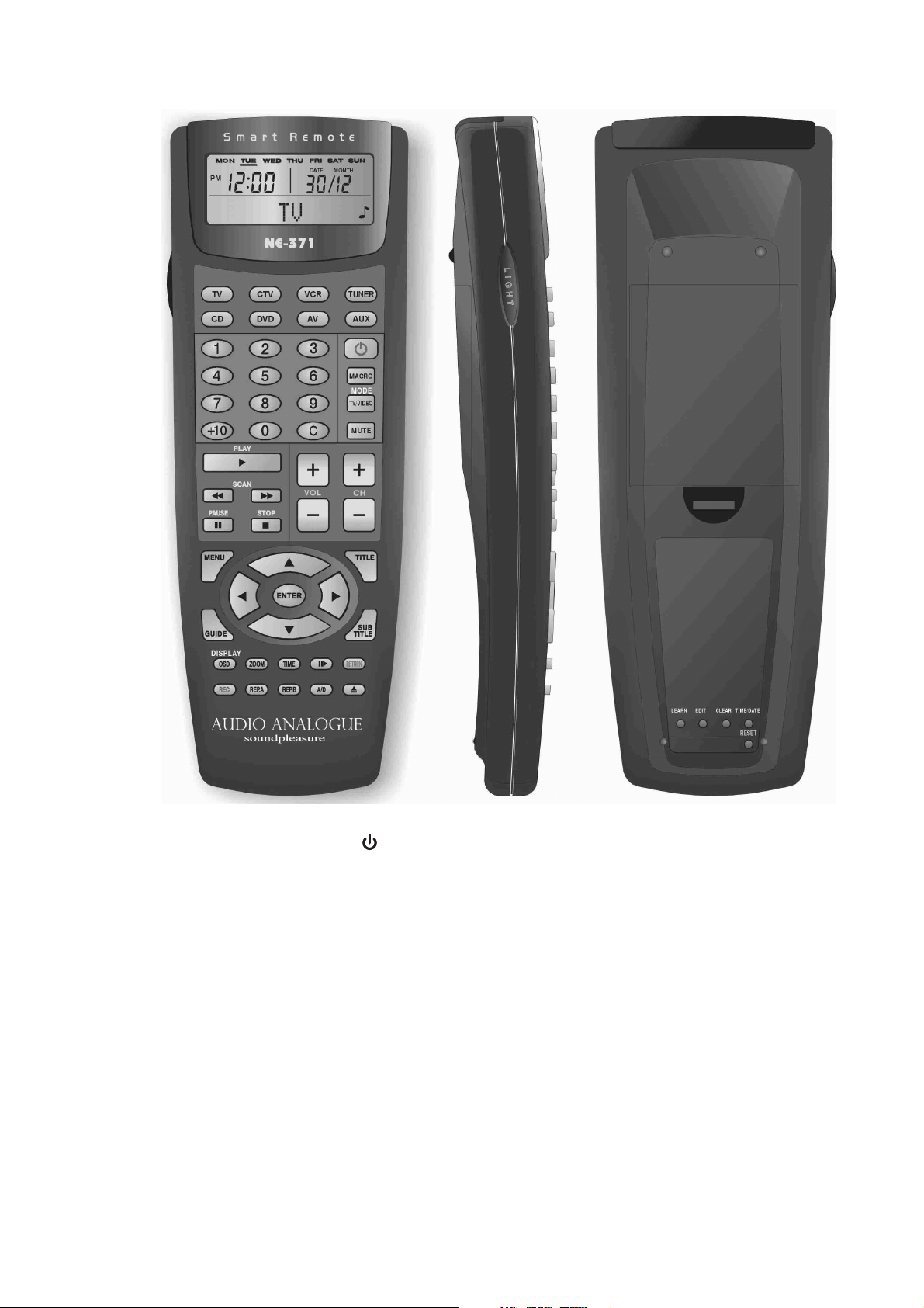
Remote control description
1 Display. It shows date and time, the active banco coding and further messages
during its use.
2
. Activates and deactivates the stand-by.
3 Processor selecting code. The remote control is able to check 8 different
equipments. It is possible to connect the banco codes related to the Cinecitta’
processor through the button’AV’. The remote control display will show the
active banco.
4 ‘MUTE’ Activates and deactivates the mute.
5 ‘CH+/CH-Selects the source for the listening
6 VOL+/VOL. Volume regulation
7 ‘MENU’ Recalls the Set Up
8 ENTER. Selects the option enhanced on the on -screen display and on the
processor’s display.
9 ‘RTN’ .Fast exit from display
10 Signals. They allow the set-up navigation
11 ‘MODE’ Selection of the type of the decoding audio
12 ‘DISPLAY’ . It regulates the intensity of the text shown on the display
13 Button to regulate the display and keyboard’s brilliance.
14 Emitter IR
15 Receiver IR for learning
Rear
1 ‘LEARN’ Button to activate or deactivate the function of learning
2 ‘EDIT’ Button to modify the names associated to the remote control’ functions.
3 ‘CLEAR’ Button to delete specific portions of memory.
4 ‘TIME/DATE’. Button to set up time and date.
5 ‘R E SET’ Button to totall y de l ete the remote control ’ me mory.
5
1
2
3
4
7
6
9
10
8
12
13
5
13
1
2
3 4
5
10
10
10
11
14
15
11
Page 12

Opening and inspecting the package.
Open the box with extreme care to avoid harming the content. The package contains
the following items:
A Cinecitta’ Processor
A remote control
Four AAA batteries (obviously in the remote control)
A supply cable
A cable for trigger connection
This manual
A CD-Rom
Whenever some of the objects above-listed were missing, please consult your Audio
Analogue dealer.
After pulling out the smallest items, take out the equipment with extreme care.
Remove the shockproof expanded foam. If the batteries are not already in the remote
control. Open the lid of the space containing batteries of the remote control and insert
them in the correct position; close therefore the lid. It will be necessary to program
the remote control as indicated later. If the remote control is already active, the
programming will not be necessary.
Cho o s in g the pl ac e whe r e to po s it io n the Ci ne ci tt a’ P ro c es so r.
The Cinecitta’ Processor is an equipment generating a considerable quantity of heat.
For this reason it is advisable to place it in an environment with a good air circulation.
In particular it is appropriate to allow a sufficient surrounding and above space. (at
least 5cm), to avoid to put it close to source o f heat (radiators, amplifiers and televisions).
12
Page 13

Connecting the Cinecitta’ Processor.
Before connecting the Cinecitta’ Processor to the sources, to the amplifier or to the
television or to the screen or to the projector, check that all the equipments are unplugged.
Firstly connect the audio and video sources to the channels of The Cinecitta’ processor
that you want to use. Whenever there are available alternatives to connect a source
to the processor, choose the best connection (for instance, it is preferable to use a digital
connection to connect a CD player, or a component connection rather than a composite
one for connecting the video exit from a DVD player). Use only best quality cables,
with gold or rhodium-plated connectors. It is obviously possible to make multiple
connections of the same source to the processor using more inputs (for instance, a
DVD reader can be connected digitally and analogically as far as the audio is concerned,
composite and in S-Video as far as the video is concerned).
Connect, therefore, the pre audio Cinecitta’ exits to the amplifier inputs of the used
amplifiers. Whenever a trigger input compatible with the trigger exit of the Cinecitta’
Processor is available on the amplifier, connect the supplied cable. Consult the technical
specifications of Cinecitta’ and of the amplifier to check to check the trigger compatibility.
Connect the Cinecitta’ Processor ‘s video exits you want to use to the channels of
Television/, screen or projector. Thanks to the supplied exits and to the functioning of
video format transcoding, it is possible to send contemporarily a RGB signal on VGA
connection to a PC monitor, a component signal connected to a projector and a composite
one to a television. This is useful if you intend to use the Cinecitta’ Processor to add
a sound track and send images to different environments.
Eventually connect the supplied supply cable to the Cinecitta’ Processor through the
appropriate vaschetta.
The of the supply cabl e ’s plug needs to be conne c t e d t o a socke t .
ATTENTION! The Cinecitta’ Processor does NOT include a switch. So if it is connected
to a socket is always supplied. Plugging needs to be done as the final step.
13
Page 14

BASIC OPERATIONAL FUNCTIONS
Switching on the Cinecitta’ Processor
When the plug of the supply cable is connected to the socket, the equipment lights up
showing an introductory message and, after few seconds the functioning condition.
Whenever this shouldn’t happen, please consult the section about the problem’s
resolution.
Even if it is advisable to switch off the equipment (disconnecting the supply cable’s
plug) when it is not used for long periods of time or during storms and electric storms,
it is possible to leave it on in between the various daily listening. In this case, it is
available the stand-by function which deactivates the equipment, silencing the audio
exits and switching off the video ones. If the trigger connection between processor and
amplifier is active, activating the stand-by provokes even the switching off of the
amplifier.
Regulating and silencing the volume (mute)
The volume’s knob on the front panel and the buttons Vol+/Vol- on the remote control
act on the general listening level. This means that the volume of active inputs is
modified from the same value. It is possible to change the levels about the various
inputs in comparison to the general listening level, influencing the set-up.
The mute button, on the front panel and on the remote control, allows to lessen the
listening level to 20dB. With a normal listening level, this is the equivalent to pass to
a musical background level.
This function is useful when is suddenly necessary to diminish the volume, for instance
to reply to a phone call or to have a conversation or more when you want to replace
the DD or the DVD. For very low volumes it is possible that activating the mute
provokes the total silencing of one or more channels. Deactivating the mute will restore
the normal listening level.
Selecting the audio inputs for the listening
Selecting the desired audio channel happens through rotating the left selector (SELECT)
or through pressing the CH+ oCH-buttons. The selection is circular, so it is possible
to pass from the last inputs of the sequence to the to the first one and vice versa without
gliding all the other ones. Analog and digital inputs are organized in the same way and
considered exactly the same. The sequence is the following one: Phone, CD, Tuner,
Aux, Video 1, Video 2, Video 3, Video 4, Tape 1, Tape 2, 8-Inputs, Coax1, Coax 2,
Coax 3, Coax 4, Opt1, Opt 2, Opt 3. The last 7 channels are digital. The Audio Channels
commutation implies the automatic video sources commutation. The associations
activated in the factory are the following ones:
Phono
CD
Tuner
Aux
Video1
Video2
Video3
Video4
Tape1
-
-
-
CVBS1
CVBS2
S-Video3
S-Video4
CVBS1T
Tape2
8-Channels
Coax1
Coax2
Coax3
Coax4
Opt1
Opt2
Opt3
S-Video2T
Component1
CVBS1
S-Video2
Component1
Component2
CVBS3
S-Video4
Component2
14
Page 15

Examples about using the channels selector.
Rotate clockwise the selector on the front panel or press the button CH+ on the remote
control to pass from Phono aCD. Rotate anticlockwise the selector on the front panel
or press the button CH-on the remote control to pass from Video 4 to Video 3.
Notes regarding organizing the audio and video channels.
The Cinecitta’ Processor includes audio analogue and digital channels and video
channels. Despite the way it looks like (it is missing of a selecting independent control
for the video source), the selecting bars system is very flexible, and allows associating
any video channel to any audio channel. This feature allows using the digital sources’
flexibility at its best. To better clarify this aspect, a universal digital reader should be
taken into consideration. The reader is able to read CD, CD-Video, DVD-Video, DVDAudio and SACD. It is equipped with a stereo analog exit, with a multi channel analog
exit and with a digital exit, and also with various video exits (composite, S-Video
component). According the international agreements against disk’s piracy, the digital
exit is usually able to transmit PCM frequency signals superior to 96KHz or DSD
signals. It is not, therefore, possible to transfer digitally from the reader to the processor
the SACD signals and DVD-Audio signals. On the other hand, the PCM digital signal
of CD or the one compressed form DVD-Video is available on the digital exit. For this
reason, it is necessary to connect all the 3 audio exits of the universal reader to the
processor: the digital exit will be used for using CDs and DVD Videos and the analog
audio exits for listening SACD or DVD-Audio. It is appropriate to use both the readear’s
analog exits because very often the stereo’a exits use internal DA converters of superior
quality in comparison to the multi-channel exits. Therefore, depending on the format
of the chosen disk, the user will select the 8 channel’s inputs l on the processor (SACD
and DVD-Audio multi-channel),or a an analog stereo channel (SACD or DVD- Audio
stereo), or again a digital channel (DVD-Video or Cd)
And what about the video inputs? In a normal processor, 3 different audio inputs
correspond to 3 other video inputs. In the case of the Cinecitta’processor is possible
to act on the set up to associate only one video input ( for instance, the one connected
to the video input of better quality than the universal reader). In this way, the video
exits of the universal reader will be available for any audio exit you want to listen to.
If you take into consideration that not only DVD-Videos but DVD-Audio also, the
SACD and some CD are supplied with images, it is easy to understand the utility of
this operational feature connected to Cinecitta’ processor.
Channel Selection for the analog recording
Selecting the wanted channel for the analog recording happens through rotating the
left selector (Select) whilst the button ‘Analog Tape’ is pressed. The selection is circular,
so it is possible to pass from the first to the last channel of the sequence and vice versa
without slipping all the other. Only the analog channels are organized on this bar. The
sequence is the following: Off, Phono, CD, Tuner, Aux, Video 1, Video 2 Video 3,
Video 4, Tape 1, Tape2 , 8 channels (only the first 2 channels are connected to the tape
bar).
The commutation of the audio channels on the analog bar implies the automatic
commutation of the video channels associated on the video tape bar. If the analog tape
bar is set on ‘Off’ (no analog source selected), on the video tape exits there will be the
video source associated to the audio digital source selected on the digital bar tape.
Notes about the recording video bar
It is available a set-up option which allows to bypass the video recording bar and send
to the tape exits the signals bound to the composite video exits and to the S-Video
exits. When this option is active, it is possible to use the function to cross convert the
video formats, to record a signal of any formats on any kind of recorder. For instance,
it is possible to record the video signal coming from the DVD player in component
format son a VCR with composite channel.
15
Page 16

Selecting the decoding way.
Depending on the selected source for the listening and on the speaker’s configuration,
one or more decoding ways of the audio signal are available. The decoding ways
available depend on the kind of source (analogical or digital) and, in case of digital
sources, on the type of compression adopted. The following table shows the decoding
ways available for every type of source or signals in the as wide as possible speakers’
configuration.
Source Compression Available decoding ways
Analogic - Stereo (bypass)
Dolby Pro Logic II
DTS Neo:6
Digital Linear PCM Stereo
(no compression) Dolby Pro Logic II
DTS Neo:6
AC3 2 Channels Dolby Digital EX + Pro Logic II
Dolby Digital + Pro Logic II
Dolby Digital EX
Dolby Digital (*)
AC3 multichannels Dolby Digital EX
Dolby Digital (*)
DTS DTS-ES
DTS (*)
*Depending on the chosen configuration for the surround speakers, different ways are
possible to address the surround inputs
It is possible to pass sequentially from a decoding way to another one, in the group
of the certified decoding ways, pressing the button ‘mode or on the frontal panel or
on the remote control.
16
Page 17

Stand-by
The Cinecitta’ processor can be put on stand-by pressing the button on the remote
control. When the processor is in stand-by all the exits are deactivated, the trigger is
off and the display shows the time. To remove the stand-by it is possible to act use
again the remote control. Alternately, it is sufficient to act on one of the checks of the
fron t pan e l : th e eq ui p me nt will re m ov e imm e di a te ly the sta n d- b y.
It is advisable to put the Cinecitta’ processor on stand by when you don’t use it. The
analog circuit will remain on and in temperature, therefore in a condition to give the
best performance, whilst the video circuits and the decoding video circuits will have
to be deactivated and kept to a room temperature, to guarantee a longer duration of
the equipment.
Display brilliance
The intensity of the text’s brilliance shown on the display can be regulated cyclically
via remote control on four different levels.
Automatic memorization of the functioning condition
It is good to remember that the Cinecitta’ Processor memorizes the various values of
the functioning parameters which have be set up from the user: Volume, mute state,
inputs selected for the listening and for the recording, decoding ways, brilliance of the
text on the display, etc. This function is useful, because it avoid to the user the
reconfiguration of the equipment when it is switched off and then switched on, or put
in stand –by and then reactivated. To avoid bad surprises about the sound, especially
at night, it is advisable to reduce the volume, wait for few seconds to make sure the
memory updating occurs, switch off the equipment at the end.
17
Page 18

Remote control
The Cinecitta’ Processor is equipped with an intelligent remote control which has been
pre-programmed with the necessary codes to check the equipment. The codes running
the Cinecitta’ Processor are memorized in the “AV” button of the remote control. The
remote-control is able to learn the codes belonging to other 7 equipments, it is so able
to control by itself a very complex equipment: processor, DVD player, satellite receiver,
television, projector, radio, etc. In case the remote control’s batteries run off , or if you
want to use an other remote control, it is possible to use the Cinecitta’ Processor to
teach the IR codes. For that purpose the Cinecitta’ processor is equipped with an IR
emitter, hidden behind the display’s left side of the front panel.
Configuration of the Cinecitta’ processor
1818
Page 19

Configuration of the Processor
The Cinecitta’ Processor is an extremely versatile equipment. Obviously, the available
functions on the front panel or on the remote control allow to access the most used
operating functions, but not the configuration parameters. To customize the configuration
of the equipment it is available a complete set up accessible from the front panel, or
from the remote control. This set up is shown both on the display of the front panel
and on the video exits on the (OSD) on-screen display.
The configuration is contained in a non volatile memory and is maintained even when
the equipment is not supplied. The set-up is organized in sections and sub-sections
according to the functionality of every parameter. Exists, therefore, an ‘audio’ section,
a video’ section etc. For every sub-section, the relative voices are grouped in a menu.
For a optimal set-up navigation, this manual will show, for every menu, the function
of each voice.
Activation of the set-up
The Set-up is recalled pressing the button “MENU” on the remote control or pressing
at the same time the buttons” Analog Tape” and “ Digital Tape” on the front panel of
the Cinecitta’ processor.
Navigation of the setup
Because of the limited space, on the front panel’s display appears only a menu function
at the time; whilst on the OSD are visualized 8 voices at the time. For this reason, and
even for slipping the various voices, to select the chosen one, and also to modify the
values of the various values of the visualized parameters, it is possible to navigate the
set up both from the front panel and the front panel.
Testing sequentially the different menu functions
In the OSD, one of the menu functions visualized is enhanced: it is the funcion to be
selected. On the display, on the front panel, the function to select, is always the one
shown. To underline another function on the OSD menu and change the one shown
on the display it is possible to use left selector on the front panel or the buttons “Up
Arrow” or “Down Arrow” on the remote control. When in the OSD menu you try to
enhance a voice proceeding the first one which has been visualized or follows the last
visualized, the menu function pass to the high or low displaying the other available
menu functions.
Selecting the enhanced function of menu
You can select a function menu pressing the button “Analog Tape” on the front panel
or on the button ENTER on the remote control.
Modifying the value of a numerical parameter
To change the value of a numerical parameter evidenced, use the left selector on the
front panel or the buttons “Right Signal” and “Left Signal” on the remote control. If
the enhanced parameters are 2 ( as in the case of time and timer regulation), use the
left selector on the front panel or the buttons “Left Signal” and “Right Signal” on the
remote control for the displayed shown on the left, use the right selector on the front
panel or the buttons “Signal up” and “Signal down” on the remote control for the
parameter shown on the right.
Menu Exit
The menus whose functions connect to other menus always show the word END.
Selecting this word you can go back to the previous menu. Selecting END on the main
menu you finish the setup. The menus, which allow the choice between a range of
values of a parameter and a direct exit: selecting a function you can modify the
parameter and you go back to the previous menu.
Emergency set up exit
It is possible to leave the set up from any menu pressing the button “RTN”. If we are
in a direct choice menu, obviously the related parameter is not modified.
19
Page 20

SET UP PRINCIPAL MENU (LEVEL 0)
Configuration
AUDIO
VIDEO
TRIGGER
TIMER
WATCH
LANGUAGE
REMOTE CONTROL
END
Description of the functions of the menu
AUDIO: Access to the sub-section of the audio parameters
VIDEO: Access to the sub-section of the video parameter
TRIGGER: Organizing menu of the trigger exit
TIMER: Organizing menu of the timer
WATCH: Menu for regulating the watch
LANGUAGE: Direct Exit menu to chose the language to use for
the setup
REMOTE CONTROL: Menu to operate the remote control
END: End of the configuration
20
Page 21

MENU CONFIGURATION >AUDIO (LEVEL 1-0)
AUDIO
SPEAKERS
LEVELS
DELAYS
FREQUENCY OF THE SUB-CUT
DOLBY
DTS
GAIN PHONO
END
Description of the functions of the menu
SPEAKERS Organizing menu for configuration of the speakers
used in the equipment
LEVELS Menu to regulate the related levels of the channels
DELAYS Menu to regulate the delays associated with the
channels
FREQUENCY OF THE SUB-CUT Direct Exit menu to chose the sub-cut channel’s
frequency
DOLBY Menu to organize the parameters associated with
the decoding multi channel Dolby Digital EX and
Dolby Pro Logic II.
DTS Menu to organize the parameters associated with
the decoding multi channel DTS-ES and
DTS Neo:6
GAIN PHONO Direct exit menu for choosing the gain of the phono
input
END Coming b a c k t o the m a i n se t -u p m en u
Page 22

MENU CONFIGURATION>VIDEO (LEVEL 1-1)
OUTPUTS
SYNCHRONISMS
VIDEO CONNECTIONS
DIRECT REGISTRATION
PROGRESSIVE OUTPUT
COMPONENT OUTPUT
STANDARD
END
Description of the voices of the menu
OUTPUTS Menu to organize the vide o o utputs
SYNCHRONISMS Menu to organize the synchronism outputs
VIDEO CONNECTIONS Menu to organize the association between
audio and video channels
DIRECT REGISTRATION Direct Exit menu for
activating/deactivating the option to
record the video signals
PROGRESSIVE OUTPUT Direct output menu for choosing the format
of the video signal in the progressive output
COMPONENT EXIT Direct output menu for choosing the
format of the video signal on the
component output
STANDARD Direct output menu for choosing the
standard video of the signals inputted and
outputted
END Coming back to the main set-up menu
Page 23

MENU CONFIGURATION>TRIGGER (LEVEL 1-2)
TRIGGER CONNECTIONS
END
Description of the functions of the menu
TRIGGER CONNECTION Menu to organize the association between each
channel and trigger output condition
END Coming back to the main set-up menu
23
Page 24

MENU CONFIGURATION >TIMER (LEVEL 1-3)
TIMER
AUTOMATIC SWITCH OFF
TIMER SET UP
END
Description of the functions of the menu
AUTOMATIC SWITCH OFF Menu to set up the delay for the automatic delayed
switch off
TIMER SET UP Menu to set up the times for switching on and off and
for different functions of the timer
END Coming back to the main set-up menu
24
Page 25

MENU CONFIGURATION >WATCH (LEVEL 1-4)
WATCH
HOW TO REGULATE THE WATCH
END
Description of the functions of the menu
HOW TO REGULATE THE WATCH Menu to regulate the time
END Coming back to the main set-up menu
25
Page 26

MENU CONFIGURATION >LANGUAGE (LEVEL 1-5)
LANGUAGE
ENGLISH
ITALIAN
FRANCAIS
DEUTCH
ESPAGNOL
PORTUGUES
Direct exit menu
26
Page 27

MENU CONFIGURATION REMOTE CONTROL (LEVEL 1-6)
REMOTE CONTROL
BASIC CODE SET UP
TEACHING
END
Description of the functions of the menu
BASIC CODE SET UP Direct Exit menu for choosing the basic code
connected to the messages received from the
remote control
TEACHING Menu for teaching the messages to an intelligent
IR Remote Control
END Coming b a c k to t he m a in s e t- u p m en u
27
Page 28

MENU CONFIGURATION>LOUDSPEAKERS (LEVEL 2-1-1)
SPEAKERS
MAIN
CENTRAL
SUBWOOFER
MAIN SURROUND
REAR SURROUND
END
Description of the functions of the menu
MAIN Co nfigura tion of the main s peakers ( front
and left and front right)
CENTRAL Configuration of the central speaker
SUBWOOFER Configuration of the subwoofer
MAIN SURROUND Configuration of the main surround speakers
REAR SURROUND Configuration of the back surround speakers
END Coming back to the Audio menu
28
Page 29

MENU CONFIGURATION>AUDIO>LEVELS (LEVEL 2-1-2)
LEVELS
FRONT LEFT OdB
CENTRAL OdB
FRONT RIGHT OdB
SUBWOOFER OdB
SURROUND LEFT CHANNEL OdB
SURROUND RIGHT CHANNEL OdB
SURR.POS.SX OdB
END
Description of the functions of the menu
LEFT FRONT Regulating the relative level (balance) of
the front left channel
CENTRAL Regulating the relative level (balance) of
the central channel
RIGHT FRONT Regulating the relative level (balance) of
the front right channel
SUBWOOFER Regulating the relative level (balance) of
the subwoofer
SURRO.PR.SX Regulating the relative level (balance) of
the main surround left channel
SURR. PR.DX Regulating the relative level (balance) of
the main surround right channel
SURR.POS.SX Regulating the relative level (balance) of
the back surround back channel
SURR.POS. DX Regulating the relative level (balance) of
the back surround right channel
END Coming b a ck to the Aud i o menu
29
Page 30

MENU CONFIGURATION>AUDI> DELAYS (LEVEL 2-1-3)
DELAYS
FRONT LEFT Oms
CENTRAL Oms
FRONT RIGHT Oms
SUBWOOFER Oms
SURROUND LEFT CHANNEL Oms
SURROUND RIGHT CHANNEL Oms
SURR.POS.SX Oms
SURR.POS.DX Oms
END
Description of the functions of the menu
FRONT LEFT Regulating the emission delay from the front left
channel. The delay can be between Oms and 5ms
CENTRAL Regulating the emission delay from the central
channel. The delay can be between Oms and 10m
FRONT RIGHT Regulating the emission delay from the front
right channel. The delay can be between Oms and
5ms
SUBWOOFER Regulating the emission delay from the
subwoofer. The delay can be between Oms and
5ms
SURROUND LEFT CHANNEL Regulating the emission delay from the main
surround left channel. The delay can be between
Oms and 15ms
SURROUND RIGHT CHANNEL Regulating the emission delay from the main
surround right channel. The delay can be between
Oms and 15ms
SURROUND REAR LEFT Regulating the emission delay from the back
surround left channel. The delay can be between
Oms and 20ms
SURR.REAR.RIGHT Regulating the emission delay from the back
surround right channel. The delay can be between
Oms and 20ms
END Coming back to the Audio menu
30
Page 31

CONFIGURATION MENU >AUDIO>FREQUENCY SUB-CUT (LEVEL 2-1-4)
SUB-CUT FREQUENCY
60Hz
80Hz
100Hz
120Hz
150Hz
200Hz
Note: Direct Choice Menu. The highest frequency cut is shown about electrostatic
diffusion systems.
31
Page 32

MENU CONFIGURATION> AUDIO>DOLBY (Level 2-1-5)
DOLBY
PLII MODE
COMPRESSION
END
Description of the function of the menu
PLII MODE Selection of the decoding mode Pro-LogicII
COMPRESSION Dynamical compression level for the
musical program for the Dolby Digital
algoritms and Dolby Digital EX
END Co m i ng ba ck to th e A u d i o me n u
32
Page 33

MENU CONFIGURATION>AUDIO>DTS (LEVEL 2-1-6)
DTS
DTS NEO:6 MODE
END
Description of the function of the menu
DTS NEO:6 MODE Se lectin g the decodi ng m ode D TS N eo:6
END Coming back to the Audio menu
33
Page 34

MENU CONFIGURATION >AUDIO>PHONE GAIN (Level 2-1-7)
PHONO GAIN
MOVING MAGNET
MOVING COIL
Description of the functions of the menu
MOVING MAGNET Selecting the standard earn for (40dB)
for the phono input
MOVING COIL Selecting the elevated earn for (60dB)
for the phono input
Note: Direct choice menu
34
Page 35

MENU CONFIGURATION>VIDEO >EXITS (LEVEL 2-2-1)
EXITS
COMPOSITE
S-VIDEO
COMPONENT
PROGRESSIVE
END
Description of the functions of the menu
COMPOSITE Activating/Deactivating the composite video exit
(connector RCA yellow
S-VIDEO Activating/Deactivating the video s-video exit
(connector mini-din 4 poli
COMPONENT Activating/Deactivating the video component exit
RCA connectors green-blue-red
PROGRESSIVE Activating/Deactivating the video progressive exit
(RCA connectors green, blue
END Coming back to the Video menu
35
Page 36

MENU CONFIGURATION>VIDEO>SINCRONISM (LEVEL 2-2-2)
SINCRONISM
COMPOSITE
PORTRAIT/LANDSCAPE
H/V PROGRESSIVE
NOBODY
Description of the functions of the menu
COMPOSITE Presenting the composite synchronism
connected to HS/CS
PORTRAIT/LANDSCAPE Presenting the landscape synchronisms
connected to the HS/CS exit and the
vertical synchronism connected to the VS
output.
H/V PROGRESSIVE Presenting the progressive landscape
synchronism connected to the VS output
NONE HS/CS outputs and deactivated VS for the
noise reduction
Direct choice menu
36
Page 37

MENU CONFIGURATION>VIDEO>CONNECTIONS (LEVEL 2-2-3)
VIDEO CONNECTIONS
AUDIO SOURCE SELECTION
VIDEO SOURCE SELECTION
CREATION OF THE CONNECTIONS
END
Description of the functions of the menu
AUDIO SOURCE SELECTION Selecting the audio input to associate it
to a video input
VIDEO SOURCE SELECTION Selecting the video input to be associated
to an audio input. The list of the video
sources includes the voice NONE.
Associating this function to an audio input
you can obtain the deactivation of the
video card when that audio input has been
selected
CREATION OF THE CONNECTIO NSActivating the association between the
audio source and the video source chosen
wi t h the 2 above functio n s . This
association implies that every time that
the chosen audio source has been selected
with the first menu function, also the
video source connected. is automatically
selected
END C oming back to the Video menu
37
Page 38

MENU CONFIGURATION>VIDEO>DIRECT VIDEO RECORDING (LEVEL 2-2-4)
DIRECT VIDEO RECORDING
DISABILITY
ABILITY
Description of the functions of the menu
DISABILITY The direct connections between the composite
monitor outputs and s-video and connected video
tape outputs are disabled.
ABILITY The tape video outputs and the monitor outputt have
the same signal
Direct choice menu
38
Page 39

CONFIGURATION>VIDEO>EXIT WAY PROGRAMME (LEVEL 2-2-5)
WAY EXIT PROGRAMME
Y Pb Pr
YpbPr NO SINCHRONISM
RGB
RGB ON GREEN SYNCRONISM
Description of the functions of the menu
Y Pb Pr The signal from the video progressive exit (if
active) is in the YpbPr format. It is present the
composite synchronism
YpbPr NO SINCHRONISM The signal from the video progressive exit (if active)
is in the YpbPr Format. The synchronisms need to
be taken from the HS/CS and VS exits
RGB The signal from the video progressive exit (if active)
is in the RGB format. The synchronisms
need to be taken from the HS/CS and VS outputs.
RGB ON GREEN SYNCRONISM The signal from the video progressive exit (if
active) is in the RG.It is present the component
synchronism on the G channel
Direct choice menu
39
Page 40

ME NU CONFIG U RATION>VID E O>EXIT WAY C O MP. (Level 2-2-6)
EXIT WAY COMP
YpbPr
YpbPr NO SYNCHRONISM
RGB
RGB SYNCRONISM ON GREEN
Direct choice menu
YpbPr The signal coming from the video component output
(if active) is in YPBcr format. The synchronisms
need to be taken from the HS/CS and VS outputs
YpbPr NO SYNCHRONISM The signal coming from the video progressive output
(if active) is
RGB The signal coming from the video progressive output
(if active) is in RGB format. The synchronisms
have to be taken from the HS/CS and VS exits.
RGB SYNCRONISM ON GREEN The signal coming from the video progressive output
(if active) is in RGB format. It is present the
composite synchronism on all the channels.
Direct choice menu
40
Page 41

MENU CONFIGURATION>VIDEO>STANDARD. (LEVEL 2-2-7)
STANDARD
AUTO 1
AUTO 2
AUTO 3
AUTO 4
NTSC J
NTSC M
NTSC 4.4
PAL BGHID
PAL N
PAL 60
PAL M
SECAM (PAL OUTPUT)
Description of the functions of the menu
AUTO 1 The processor accepts and recognizes automatically
video signals in PAL format BGHID and NTSC M.
AUTO 2 The processor accepts and recognizes automatically
video signals in PAL format BGHID and NTSC J
AUTO 3 The processor accepts and recognizes automatically
video signals in PAL format NTSC M
AUTO 4 The processor accepts and recognizes automatically
video signals in PAL format and NTSCJ
NTSCJ The processor accepts NTSC J standard video
signals
NTSC M The processor accepts NTSC M standard video
signals
NTSC 4.43 The processor accepts compatible NTSC 4.43
standard video signals
PAL BGHID The processor accepts PAL BGHID standard video
signals
PAL N The processor accepts PAL N standard video signals
PAL60 The processor accepts PAL60 standard video
signals
PAL M The processor accepts PAL M standard video
signals
SECAM (PAL EXIT) The processor accepts SECAM standard video
signals. Standard PAL BGHID present on the outputs.
Note: Direct choice menu.
The AUTO are good for situations in which one or more multi standard sources need
to be connected to a TV or a plasma, or multi standard projector. The NTSC 4.43
format , PAL 60 and SECAM (PAL EXIT) are useful with VCR old sources and plasma
TV or non multi standard projectors.
41
Page 42

MENU CONFIGURATION>TRIGGER >TRIGGER CONNECTIONS. (LEVEL
2-3-1)
TRIGGER CONNECTIONS
SOURCE SELECTION
TRIGGER MODE
CREATION OF THE CONNECTIONS
END
Description of the functions of the menu
SOURCE SELECTION Selecting the audio input, which you want
to associate to a trigger exit.
TRIGGER MODE The way the trigger works when the audio
source is selected
CREATION OF THE CONNECTIONS Activating the association between the
audio source and the trigger modes chosen
END Coming bac k t o t he trigg er menu
Note: The audio sources ‘list includes the function ALL. If the trigger mode associated
to this voice is different from OFF, it is considered valid for all the audio inputs and
the trigger modes selected for the single audio will be ignored.
42
Page 43

MENU CONFIGURATION>TIMER>AUTOMATIC SWITCHING OFF. (Level
2-4-1)
AUTOMATIC (0 MIN.)
ADDS 30 MINUTES
END
Description of the functions of the menu
ADDS 30 MINUTES Adds 30 minutes to the countdown for the switching
off shown in the menu title. If you try to add
30minutes when the set up time is 90 minutes, the
automatic switching off function will be
deactivated.
END Coming back to the TIMER menu
43
Page 44

MENU CONFIGURATION>TIMER>TIMER SET UP. (Level 2-4-2)
TIMER SET UP
TIMER MODE
TIMER ON
TIMER OFF
END
Description of the functions of the menu
TIMER MODE Selecting the way the timer works
TIMER ON to set up the timer to switch on the processor
TIMER OFF To set up the timer to switch on the processor
END coming back to the TIMER menu
44
Page 45

MENU CONFIGURATION>WATCH >WATCH SET UP. (Level 2-5-1)
WATCH SET UP
Hh:mm
Description of the functions of the menu
Hh:mm: current memorized time in watch internal processor. To change the time, rotate
the left knob, to change the minutes rotate the right knob. To confirm the set up timer
an d to go back to the watch menu press the button ANALOG TAPE
45
Page 46

MENU CONFIG URATION>WATCH>WATCH SET UP. (Level 2-5-1)
TO SET UP THE BASIC CODE
BASIC CODE 16
BASIC CODE 19
Description of the functions of the menu
BASIC CODE 16 The processor will accept IR commands whose group code
is 16
BASIC CODE 19 The processor will accept IR commands whose group code
is 19
Direct choice menu
46
Page 47

MENU CONFIGURATION>REMOTE CONTROL>TEACHING. (LEVEL 2-7-2)
TEACH IR CODE
INCREASE THE VOLUME
DIMINISH THE VOLUME
MUTE
SUCCESSIVE SOURCE
PREVIOUS SOURCE
MODE
MENU
ENTER
COME BACK
SIGN UP
SIGN DOWN
LEFT SIGN
RIGHT SIGN
STAND-BY
DISPLAY BRILLIANCE
END
Note: Teaching of the IR codes to an intelligent remote control through the IR emitter
hidden from the plexiglass of the display, left side. Select the function of the command
you want to teach using the left knob, then press the button ANALOG TAPE to activate
the enter of a train of IR commands. The enter of a train of commands will be shown
on the display.
47
Page 48

Technical specification
Parameter
Number of channels
Gain of the stadium line
Ga in o f the phono stadi um
Reply in frequency
Ripple of the reply in frequency
Level of noise
Connection signal/noise
Alimentation
Absorption
Dimensions
Weight
Value
8
12dB
40dB
60dB
2Hz-100kHz +0/-3dB
10Hz-24kHz +0/-3dB
2Hz-22.05kHz +0/-3dB
2Hz-75kHz +0/-3dB
2Hz-24kHz +0/-3dB
20Hz-20kHz +0/-3dB
<0,1dB
<0,5dB
120dB under 1Vrms
TBD
TBD
TBD
230V 50-60Hz or 115V 50-60Hz
110VA
445mm(w)x400mm(d)x130mm(h)
12,2Kg
48
Size conditions
-
20Hz- 20kHz
moving magnet: 1kHz
moving coil: 1kHz
Line analog inputs, STEREO mode
Line analog inputs, Pro Logic II or DTS Neo: 6
Di g i t a l inpu t s , PCM 44.1 kHz, ST E R E O mo d e
Digital inputs, PCM 19 2 kH z , STEREO mode
Electrical digital inputs IEC 60937, Dolby Digital EX mode
Phono input, 40dB gain, STEREO mode
Analo g lin e inputs, STEREO mode, 20Hz-20k Hz
Phono input 40 dB gain,STEREO mode, 20Hz-20kHz
Analog la n e input s , phono input, 40 dB gain,
ST E R E O mo d e, 20 Hz-20kHz, 4VMs exit level,
OdB (volume:79)
Analog lane inputs, STEREO mode, 20Hz-20kHz,
4VMs e x i t l e ve l , le ss e n i ng OdB ( v ol u m e 7 9)
Phono inputs, STEREO mode, 40 dB gain,
ST E R E O mo d e, 20 Hz-20kHz, 4VMs exit level,
lessening OdB (volume 79)
Phono inputs, STEREO mode, 60 dB gain,
ST E R E O mo d e, 20 Hz-20kHz, 4VMs exit level,
lessening OdB (volume 79)
-
-
-
-
 Loading...