

Page 1
Service.
Self-Study Programme 205
6-speed manual gearbox 02M
Design and Function
Page 2
Adapting modern automobiles to meet the
rapidly growing demands on driving comfort,
environmental compatibility and driving performance calls for advanced improvements in gearbox technology. Adding more gears means
smoother running and enables the gearbox to be
adapted better to the characteristics of the
various engines; it also contributes indirectly to
reducing exhaust emissions by enabling torque
to be utilised more effectively.
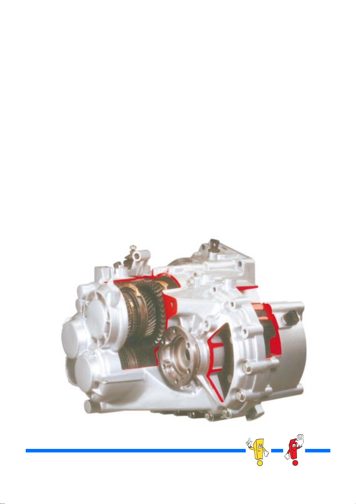
6-speed manual gearbox 02 M is a new
development. It is a compact gearbox with six
forward gears for A-platform vehicles with transversely mounted engine.
A compact 6-speed gearbox was realised by
using two output shafts and one input shaft. In
this booklet, we will explain to you the new gearbox and the technology used.
The Self-Study Programme
is not a Workshop Manual.
2
205_052
NEW Important
Note
Please always refer to the relevant Service Literature
for all inspection, adjustment and repair instructions.
Service Literature.
Page 3

Contents
Introduction . . . . . . . . . . . . . . . . . . . . . . . . . . . . . . . . . . 4
Gearbox mechanism. . . . . . . . . . . . . . . . . . . . . . . . . . . 7
Installation angle. . . . . . . . . . . . . . . . . . . . . . . . . . . . . . . 7
Design. . . . . . . . . . . . . . . . . . . . . . . . . . . . . . . . . . . . . . . . 8
Power transfer . . . . . . . . . . . . . . . . . . . . . . . . . . . . . . . . 12
Cable-operated gearshift mechanism. . . . . . . . . . . . 14
Service . . . . . . . . . . . . . . . . . . . . . . . . . . . . . . . . . . . . . 20
Sensors . . . . . . . . . . . . . . . . . . . . . . . . . . . . . . . . . . . . 22
Test your knowledge. . . . . . . . . . . . . . . . . . . . . . . . . . 24
3
Page 4

Introduction
How many gears does a car need?
There are many reasons for introducing gearboxes with more than five forward gears. Most
importantly, it is a way to match the gearbox and
the engine even better than before. A second
major reason is that the gearbox can help make
modern vehicles more environmentally friendly.
Why a 6-speed gearbox?
6-speed gearboxes have the following advantages over 5-speed gearboxes:
- More driving comfort (e.g. through
smoother running),
- Better environmental compatibility
(low fuel consumption = lower
exhaust emissions),
- Better torque utilisation
(the engine runs more in the “efficient torque”
band),
- 6-speed gearboxes allow engines with a high
power output to be driven sportily.
Depending on the engine type used, a distinction
is drawn between two modes:
- A sporty mode for engines with high power
output to quickly transfer high input torque,
- A comfortable mode for exceptionally smooth
running, which is achieved thanks to more
balanced and even transfer of input torque.
What engines will be equipped with this gearbox in model year 1999?
- 1.9-ltr. 66kW TDI engine
- 1.9-ltr. 85kW TDI engine
- 1.9-ltr. 110kW TDI engine
- 1.8-ltr. 132kW 5V turbocharged engine
- 1.8-ltr. 165kW 5V turbocharged engine
- 2.3-ltr. 125kW V5/4V engine
- 2.8-ltr. 150kW VR6/4V engine
4
Page 5
Specifications
- Gearbox designation: 02 M
- Forward gears: 6
- Reverse gears: 1
- Maximum input torque: 350 Nm
- Method of installation: Transverse mounting
- Gear oil: DEA DES-5080
- Weight: 48.5 kg (front-wheel drive)
68 kg with angle drive (four-wheel drive)
Ratios and layouts
We do not intend to present all the possible variants here, as this would be beyond the scope of this booklet.
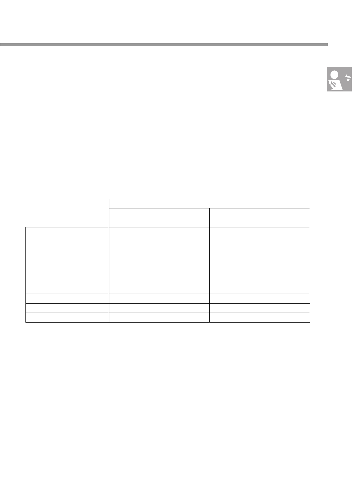
Instead, we will explain the principle by which the gearbox ratio is calculated using two examples:
Engine
2.8-ltr. 150kW VR6 / 4V 1.9-ltr. 85kW TD
Ratio Overall ratio Ratio Overall ratio
1st gear/drive pinion set I 41 : 12 = 3.417 14.351 41 : 11 = 1 : 3.818 12.363
2nd gear/drive pinion set I 40 : 19 = 2.105 8.841 40 : 19 = 1 : 2.105 6.816
3rd gear/drive pinion set I 40 : 28= 1.429 6.002 39 : 29 = 1 : 1.345 4.360
4th gear/drive pinion set I 37 : 34 = 1.088 4.470 35 : 36 = 1 : 0.972 3.147
5th gear/drive pinion set II 34 : 31 = 1.097 3.640 32 : 33 = 1 : 0.970 2.537
6th gear/drive pinion set II 31 : 34 = 0.912 3.024 29 : 36 = 1 : 0.806 2.108
Reverse gear/drive pinion set II (30 : 12) * (23 : 14) = 4.107 13.620 (31 : 11) * (23 : 14) = 4.630 12.108
Ratio, drive pinion set I 63 : 15 = 4.200 68 : 21 = 3.238
Ratio, drive pinion set II 63 : 19 = 3.316 68 : 26 = 2.615
Mode sport comfort
For a gearbox with two output shafts, the overall
ratio comprises two factors:
firstly, the ratio of the input shaft to the output shaft
(you will find this value in the table under Ratio).
Secondly, the ratio between the output shaft and the
differential.
For reverse gear, the ratio of the reverse shaft must
still be taken into consideration, so the ratio comprises two values.
The ratio for a particular gear multiplied by the
ratio for a particular drive pinion set gives the
overall ratio for the gear. This value is printed in
bold in the table.
5
Page 6
Introduction
Gearbox versions
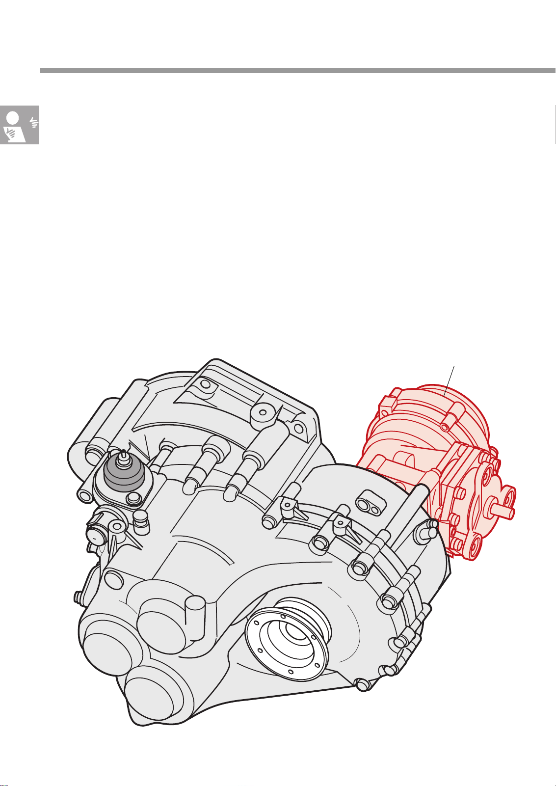
There are two different gearbox versions:
- The version for vehicles with front wheel drive
and
- the version for vehicles with four-wheel drive.
The 4-wheel-drive version of the gearbox has an
additional transfer case for driving both the front
and rear axles.
Transfer case for
four-wheel drive
205_001
6
Page 7
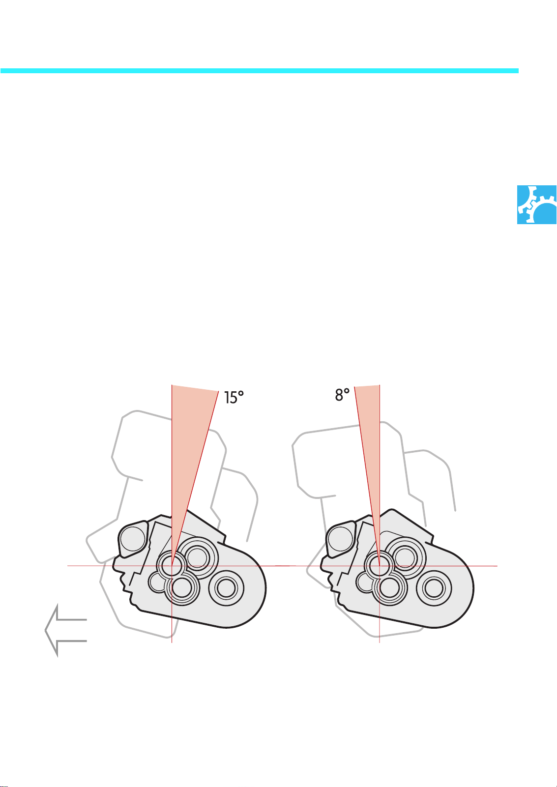
The installation angle
Gearbox mechanism
of the gearbox is dependent on the
engine type being used.
Two different installation positions are possible:
- tilted back by 15°
for 4-cylinder engines and
- tilted forward by 8°
for VR6 engines.
The term "installation angle" describes the angle
at which the bolt holes on the engine flange are
offset to match the engine’s angle of tilt. The
gearbox itself is not tilted.
Direction of
travel
205_031205_032
VR6 engine4-cylinder engine
7
Page 8
Gearbox mechanism
Design
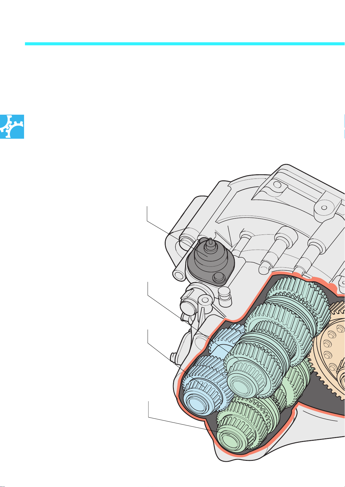
In a conventional gearbox, an input shaft transfers drive force to an output shaft on which the
various gears are positioned. The more gears
there are lined in row on such a drive shaft, the
longer it will be.
Selector shaft
For the so-called short gearbox, one of which is
manual gearbox 02 M, VW uses two output
shafts - on which the gears are arranged instead of one.
This reduces the installation length considerably.
Output shaft 1
Input shaft
Output shaft 2
8
Page 9
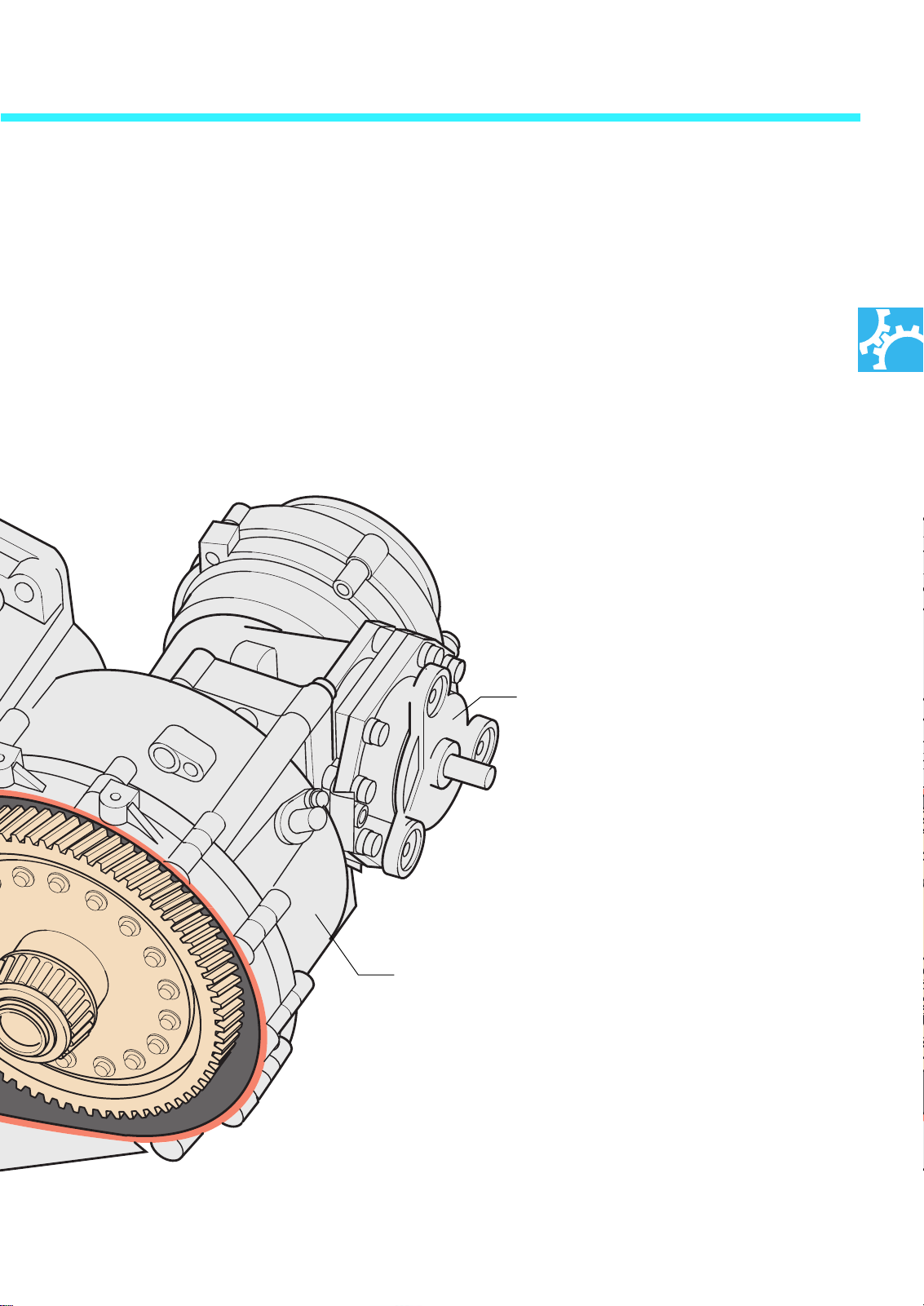
Manual gearbox 02 M has one input shaft and
the two output shafts, TW1 and TW2.
The gears are arranged on both output shafts as
follows:
- TW1: Forward gears 1 to 4
- TW2: 5th and 6th gear and reverse
The reverse gear comprises a reverse shaft with
two gears via which the direction of rotation is
reversed. (In the illustration below, the reverse
shaft is hidden by the input shaft.)
Transfer case
for four-wheel drive
205_009
Housing
9
Page 10
Gearbox mechanism
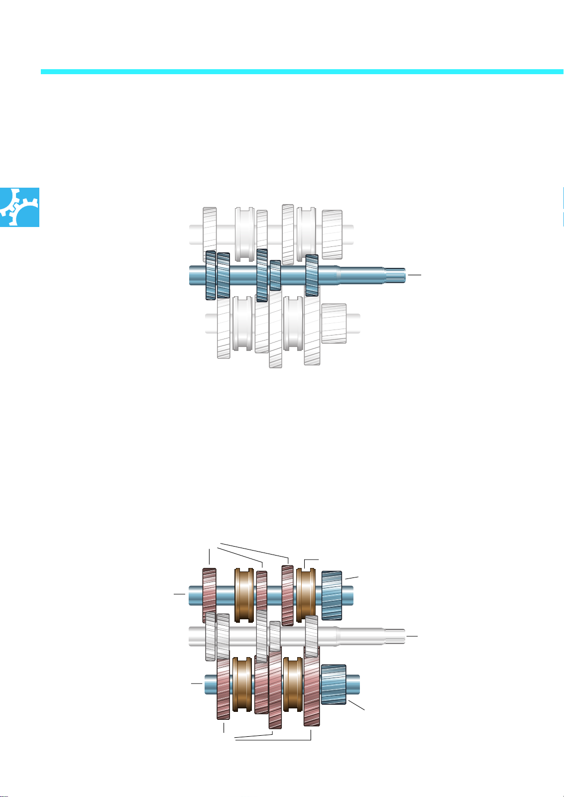
Design of input shaft
The gear wheels of the input shaft are designed
as fixed gears, i.e. they are permanently linked
to the input shaft.
Input shaft
with fixed gears
205_047
Design of output shafts TW1 and TW2
The gear wheels run in needle bearings and can
rotate on the output shaft. This is why they are
also known as sliding gears. Only when the
appropriate gear has been selected is the sliding
gear connected to the fixed gear of the output
shaft via a sliding sleeve and a synchromesh
body.
Sliding gears
Output shaft
with sliding gears
The sliding gears of the output shaft are
continuously in mesh with the matching fixed
gears of the input shaft, i.e. the sliding gears also
rotate continuously. As the sliding gears - with
the exception of the idler of the engaged gear are not permanently linked to their output shaft,
they transfer no torque to the output shaft in this
state.
Sliding sleeve with synchromesh body
Fixed gear to differential
TW2
Input shaft
with fixed gears
10
Output shaft
with sliding gears
Sliding gears
TW1
Fixed gear to differential
205_048
Page 11
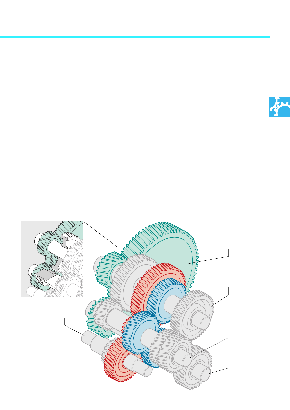
Double gearing
Replacing the conventional output shaft with two
shorter output shafts alone is not enough to
achieve a short, compact design. It is still necessary to find a way to transfer torque to both output shafts without requiring more components.
In the case of manual gearbox 02 M, this problem is solved by means of double gearing. In a
double gearing arrangement, a fixed gear of the
input shaft is linked to a sliding gear of TW1 and
a sliding gear of TW2. In this way, two gears can
be driven by only one fixed gear on the input
shaft.
To achieve different ratios, opposed sliding gears
have different diameters and therefore different
numbers of teeth.
Gears of the TW2 have a larger diameter than
the gears of the TW1.
This results in a 25% speed differential
between the output shafts.
Manual gearbox 02 M has three
double gearings:
- Sliding gear wheel, 1st gear, on TW1 and
reverse shaft with the the input shaft (red),
- Sliding gear wheel, 4th gear, on TW1 and
sliding gear 6th gear on TW2 with the input
shaft (blue) and
- TW1 and TW2 with the
differential gear (green).
205_030B
Differential gear
Output shaft 1
Reverse shaft
Input shaft
Output shaft 2
205_030
11
Page 12
Gearbox mechanism
R
205_010
Power transfer
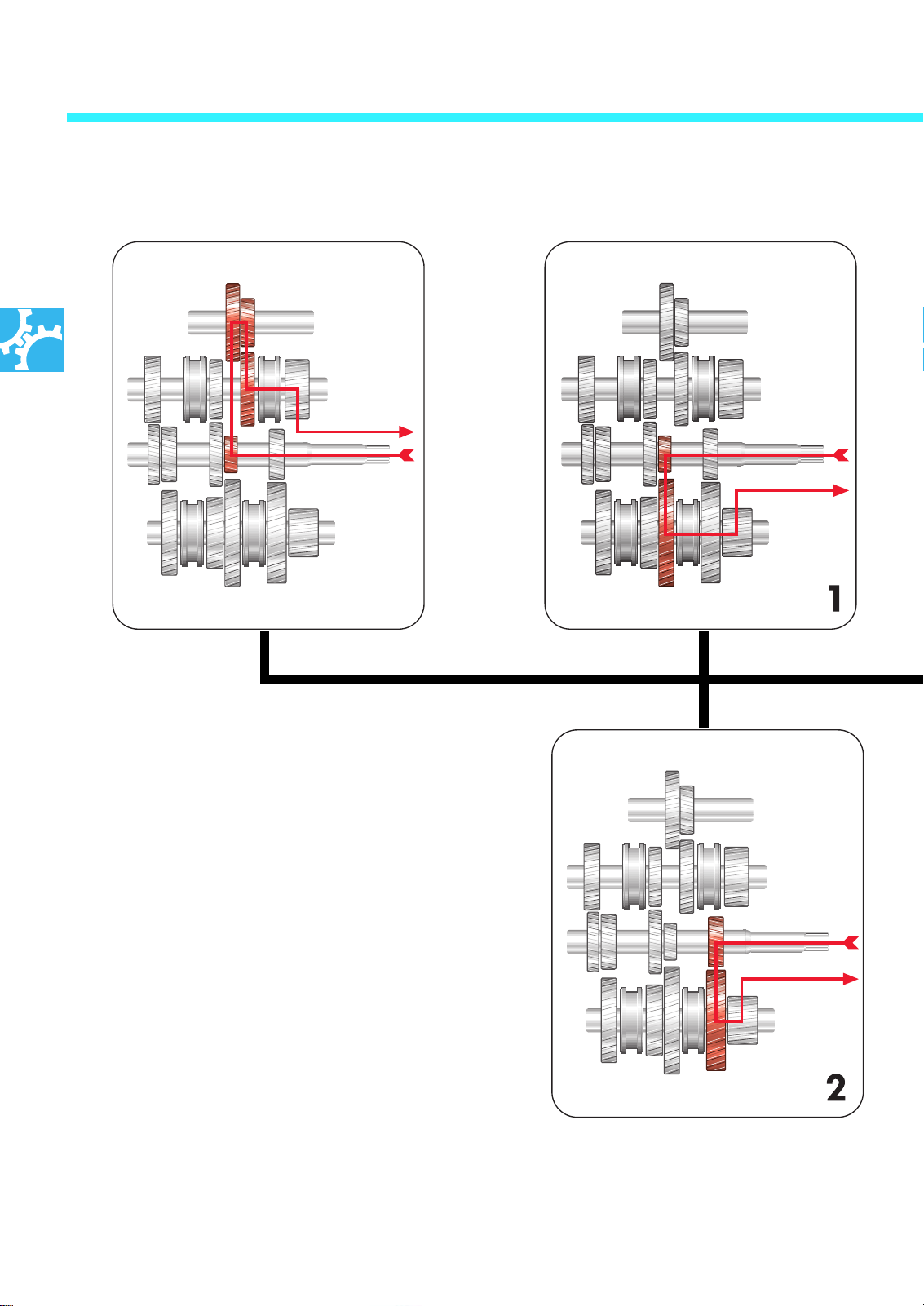
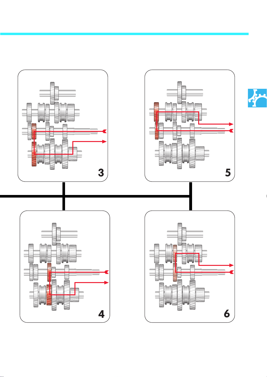
Since gearbox 02M has two output shafts, power
is either transferred via the one shaft or via the
other shaft to the differential, depending on what
gear is selected.
Taking the selection diagram for the sake of clarity, the individual gears can be assigned to the
power transfers shown in the figure on the right.
205_011
12
205_012
Page 13
205_013 205_015
205_014 205_016
13
Page 14
Cable-operated gearshift mechanism
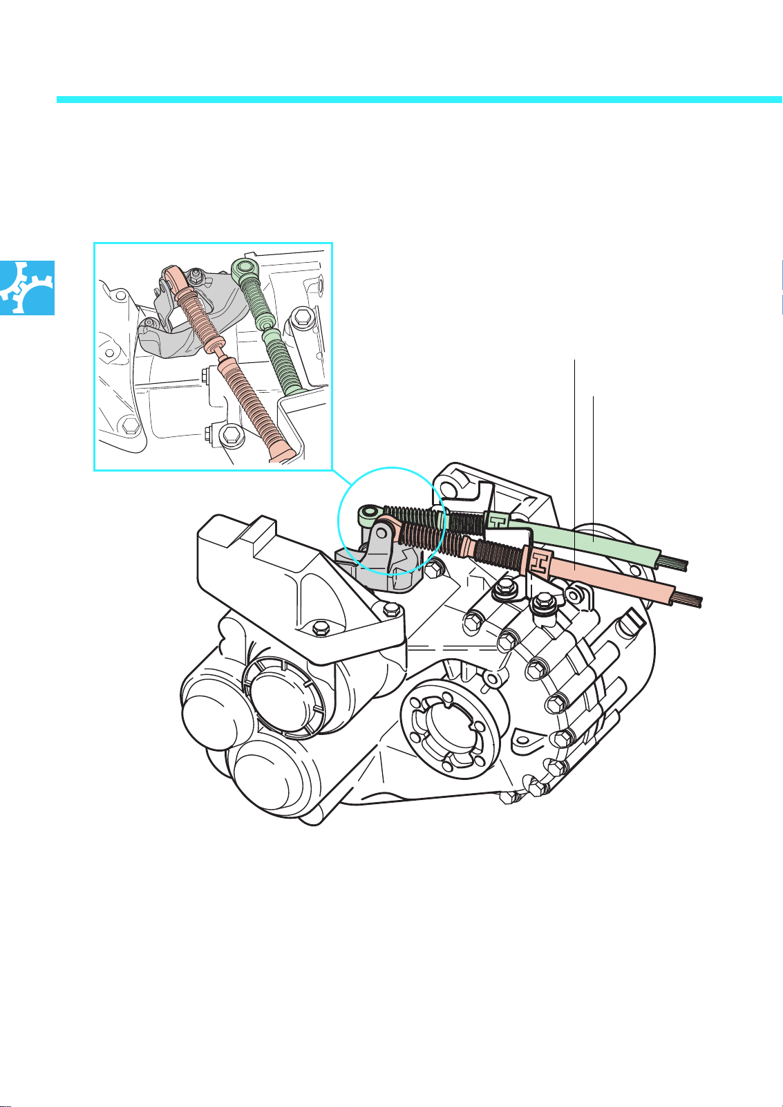
The two selector cables of the cable-operated gearshift mechanism
establish the connection between the gear lever and gearbox 02 M.
Mechanism for transferring the
motion of the selector cables to the
selector shaft.
Selector cable
Gear selector cable
205_027
The two selector cables transmit the motions of
the gear lever to the gearbox selector shaft. The
mechanism shown above translates the movement of the selector cables into a movement of
the selector shaft in the gearbox.
205_028
14
Page 15
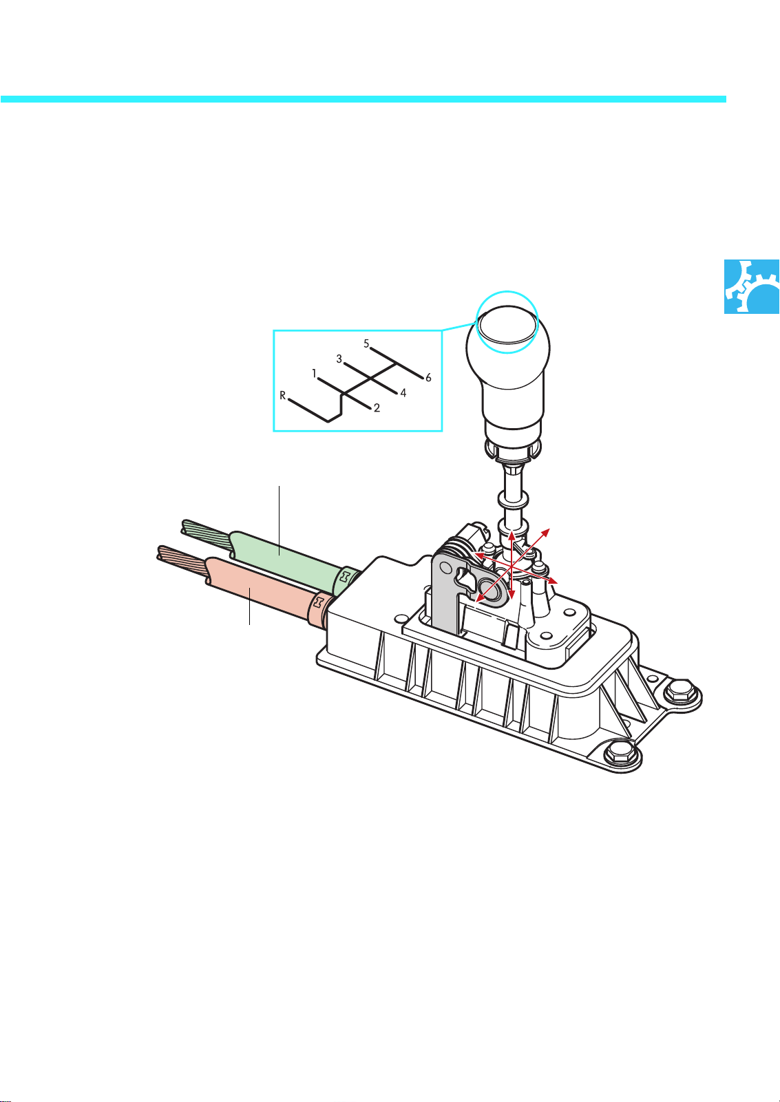
Gear lever
The position of the gears is in accordance with the VW standard, except that an extra gear
has been added to fill a previously unallocated space.
205_004
Shift motion
Selection motion
The gear lever can be moved in the direction of
the three spatial axes. The mechanism of the
gear lever splits the gearshift operation of the
driver.
- A part of the mechanism transfers the
right/left motion of the gear lever to the
selector cable. With this operation, the driver
selects the gate to be selected.
205_029
- The other part of the mechanism transfers
the forward/reverse motion to the gear
selector cable. With this operation, the driver
engages the desired gear.
15
Page 16
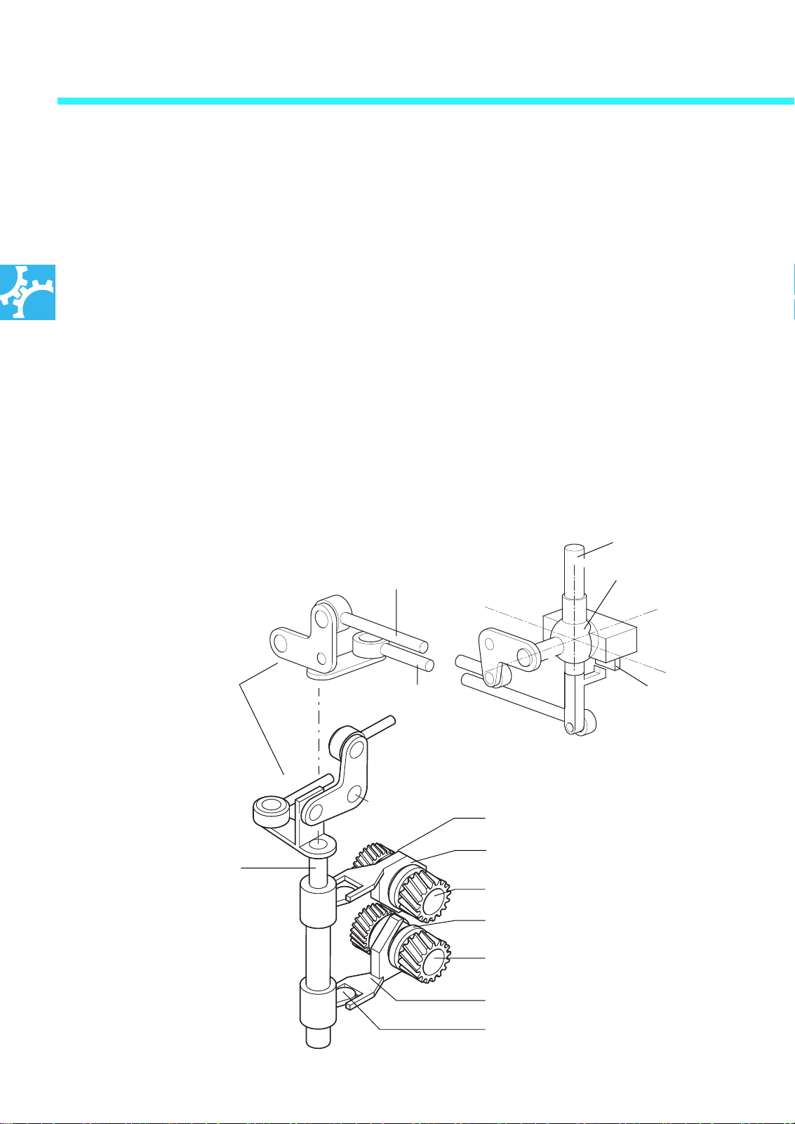
Cable-operated gearshift mechanism
Selecting a gear
In essence, gear selection consists of three components of the selector mechanism and gearbox:
●
The gear lever mechanism translates the
driver's operations.
●
The selector cables transfer the operation
of the selector lever mechanism to the
gearbox selector shaft.
●
The selector shaft mechanism on the gearbox.
This mechanism selects and engages the gear
wheel of the gear selected.
Selector cable
We will explain to you the sequence of operations when selecting a gear by means of three
examples.
For the sake of clarity, we will split the selection
sequence into
- operations outside the gearbox
and
- operations inside the gearbox
Gear lever
Ball joint
Mechanism for transfer-
ring the motions of the
cable pull to the selector
shaft.
Selector shaft
Gear selector cable
205_049
Interlock
205_050
Shift fork
Sliding sleeve with synchroniser ring
Output shaft 1
Sliding sleeve with synchroniser ring
Output shaft 2
Shift fork
Shift finger
16
Page 17
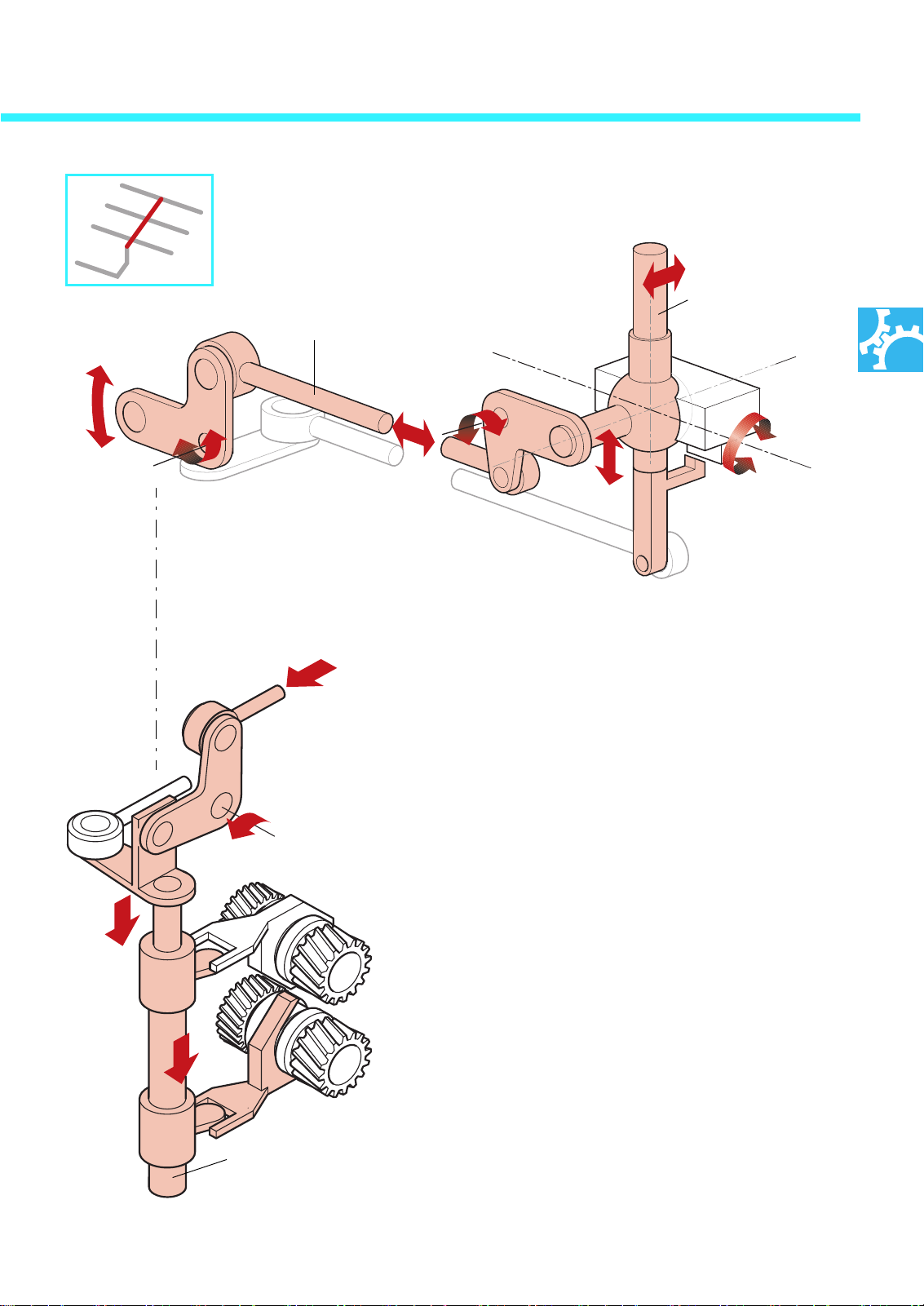
Left/right motion of the gear lever
205_045
Gear lever
Selector cable
205_024
The gear lever mechanism transfers the right/
left motion of the gear lever to the selector
cable. The gearbox mechanism translates the
motion of the gear selector cable into an up/
down movement of the selector shaft.
Selector shaft
205_022
In the gearbox, this up/down motion causes
the shift finger on the selector shaft to move
upwards or downwards. The shift finger for
the selected gear pair then reaches into the
cutout in the relevant shift fork.
17
Page 18
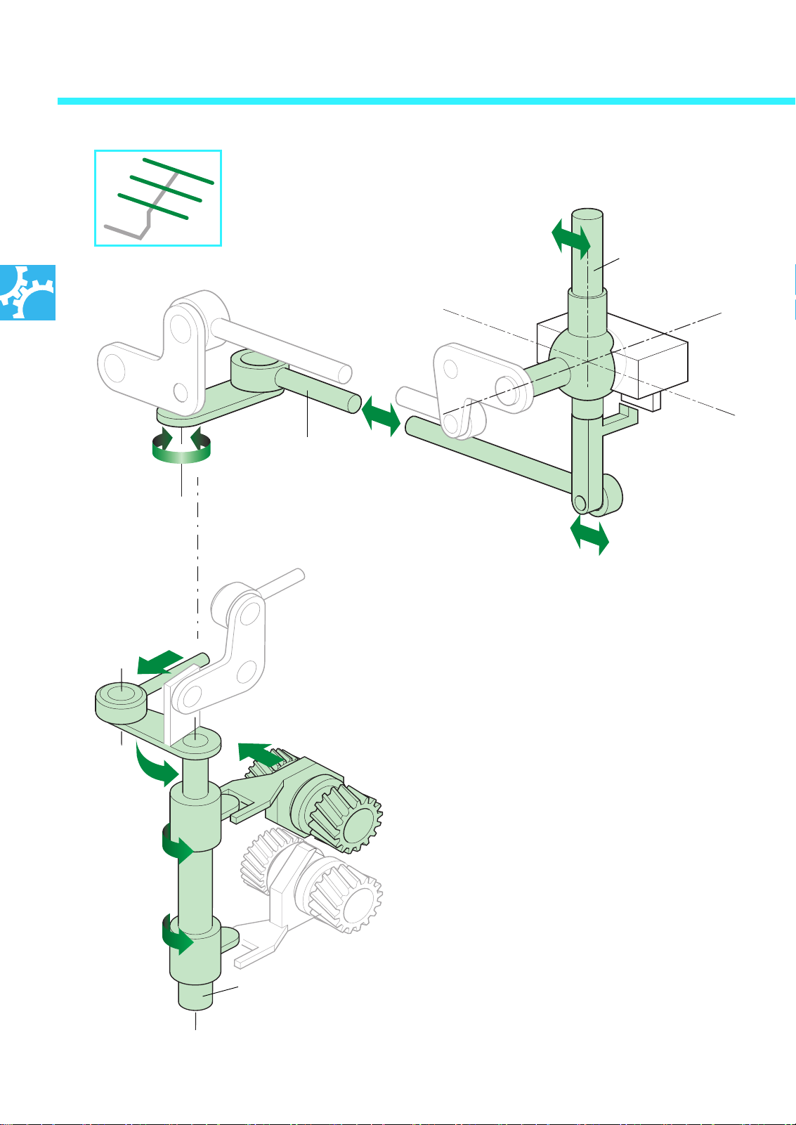
Cable-operated gearshift mechanism
Forward and reverse motion of gear lever.
205_044
Gear lever
Gear selector cable
205_025
The forward and reverse motions of the gear lever is
transferred to the shift cable. The gearbox mechanism
translates the motion of the gear selector cable into a
rotational motion of the selector shaft.
18
In the gearbox, this rotational motion of the selector
shaft causes the shift finger which has engaged in the
cutout in the shift fork to move the shift fork and gear
change sleeve sideways.
The gear change sleeve links the gear wheel of the selected gear to the output shaft. The selected gear is
then selected.
Selector shaft
205_023
Page 19
Selecting reverse gear
205_026
205_046
Spring
Ball joint
Gear lever
Interlock
Gear lever
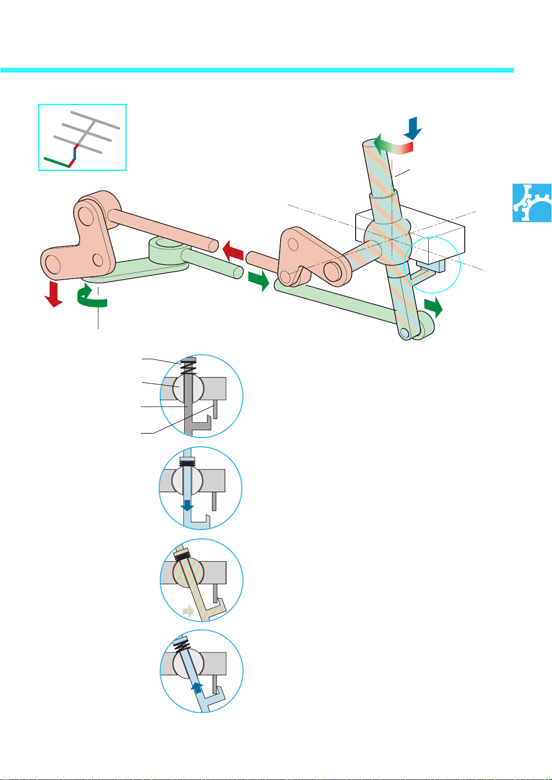
Selecting reverse gear represents a special case,
since an interlock must first be cancelled in order
to engage this gear.
205_040
205_041
205_042
205_043
Press down the interlock against the force of the
spring and the gear lever will slide down through
the ball joint.
Only then can the interlock be cancelled in order
to engage reverse by moving the gear lever to
the left and forwards.
A spring pulls the gear lever back up.
19
Page 20
Service
Adjusting the cable-operated gearshift mechanism
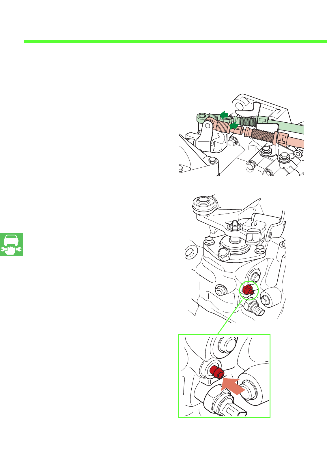
The procedure for adjusting the cable-operated
gearshift mechanism has been simplified:
- Pull the spring at both ends of the cable pull
back.
- Fix the springs by a rotational motion with the
plastic nuts (arrows).
205_034
- Attached to the gearbox housing is an adjusting pin which fixes the selector shaft in a
predefined position. Move the selector shaft
by hand into the gate of first and second gear
and then press the adjusting pin into the
gearbox housing. The gearbox pin latches
home in this position and locates the selector
shaft.
205_036
20
205_020
Push in the setting pin
Page 21
205_021
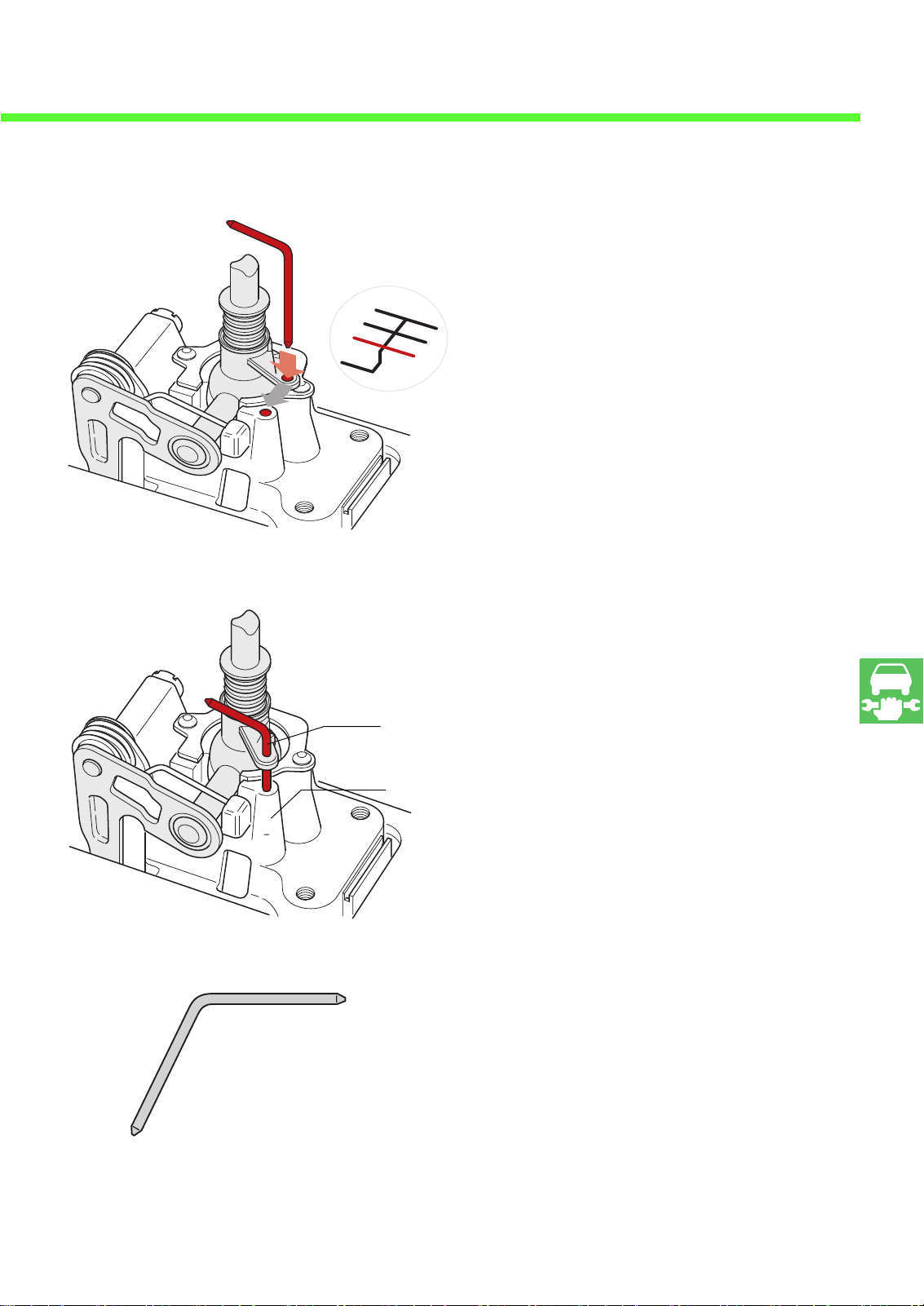
- You still have to move the gear lever into
the first and second gear positions. In the
figure, you can see two guide holes: one on
the gear lever and one in the housing.
- To fix the gear lever in place, pass locating
pin T10027 through bore A into bore B when
they are exactly one above the other.
Locating pin T10027
205_052
A
B
205_035
- Now you can let the springs on the selector
cables snap back into place. Detach the adjusting pin from the gearbox housing and pull
the locating pin T10027 back out.
21
Page 22
Sensors
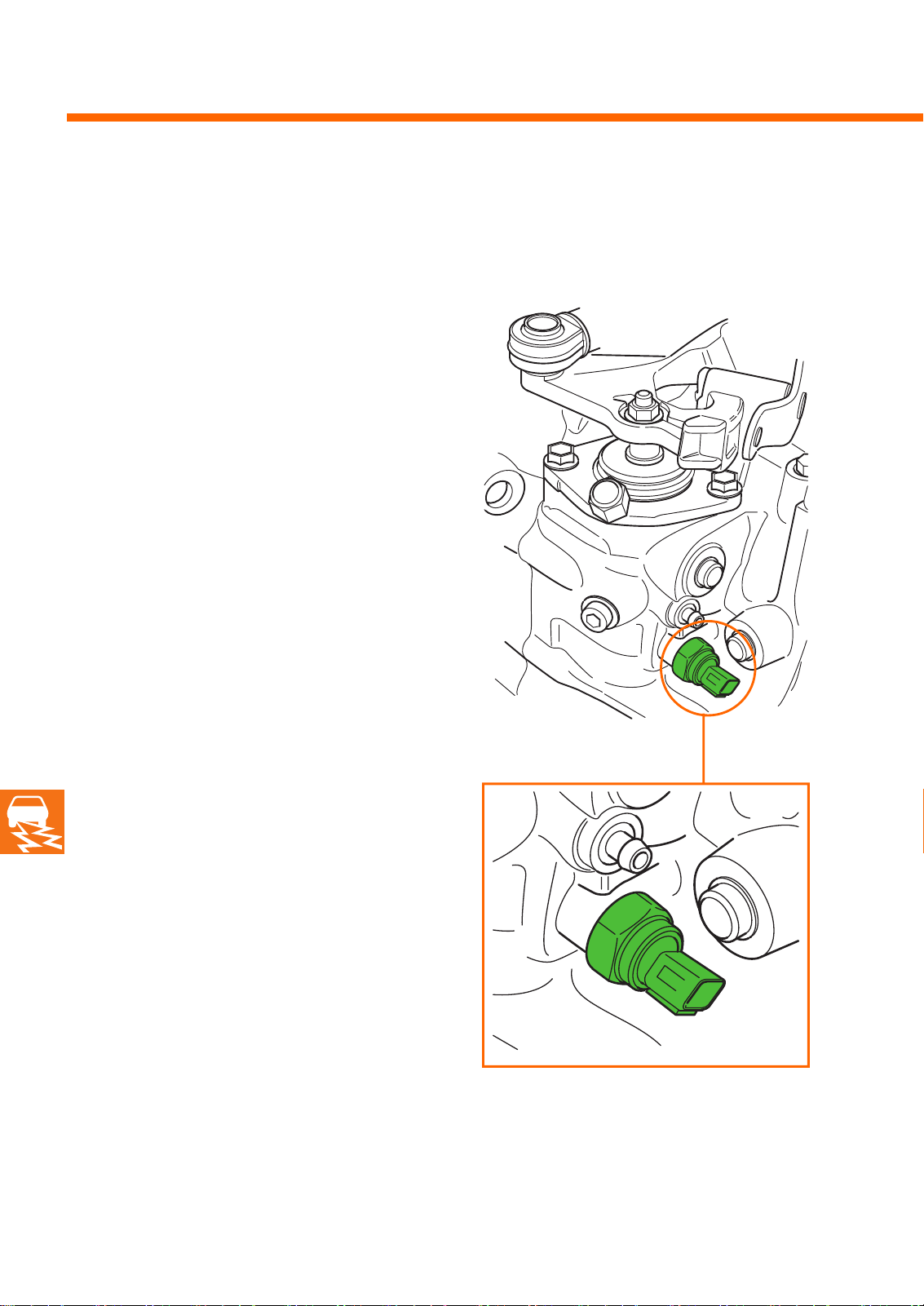
Gearbox 02 M is equipped with two sensors:
- Switch for the reversing lights F4
- Speedometer sender G22
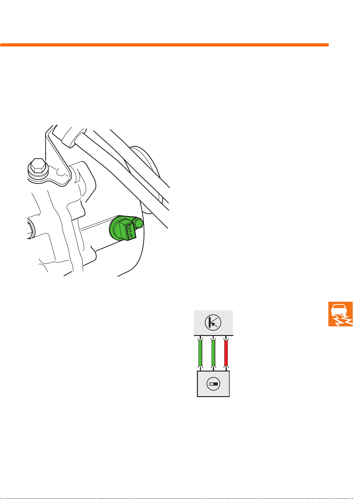
Switch for reversing lights F4
The reversing light switch is activated when the
selector shaft engages the reverse gear. The
reversing light switch has a two-pin connector
and is arranged below the adjusting pin for the
selector mechanism.
Task
When engaging reverse, the electrical circuit to
the reversing lights is closed via this switch.
205_037
22
205_003
Page 23
Sensors
Speedometer sender G22
The speedometer sender is bolted to the gearbox
housing and scans a sender wheel on the differential.
Task
It records the vehicle's road speed for the control
unit with display unit in the dash panel insert.
205_033
Effects of failure
If the sender fails, the speed limiter cuts in
earlier.
Electrical circuit
G22
205_051
23
Page 24
Test your knowledge
1. What are the advantages of a 6-speed gearbox?
a) greater smoothness
b) higher speed
c) better environmental compatibility
2. Why does the 02M have two output shafts?
3. How are the gears arranged on output shafts TW1 and TW2?
TW1:
TW2:
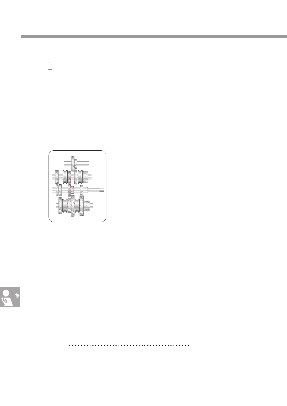
4. Show the power train for the 6th gear in the drawing.
205_017
5. Explain the concept of “double gearing”?
6. Arrange the following steps for setting the cable-operated gearshift mechanism in the correct order:
a) Press in the adjusting pin into the gearbox housing.
b) Let the springs on the both selector cables snap back into place.
c) Move the gear lever in the correct position and fix in place with a pin.
d) Pull the locating pin out of the gear lever.
e) Move the selector shaft into the adjustment position by hand.
f) Pull the spring back out of the selector cables.
g) Remove the adjusting pin from the gearbox housing.
Solution:
24
Page 25

Notes
25
Page 26

Notes
26
Page 27
205_016
6. f, e, a, c, b, g, d.
shaft and a gear of the second output shaft. However, only one gear is engaged at any given time.
5. With double gearing, one gear of the input shaft is in mesh with both a gear of the first output
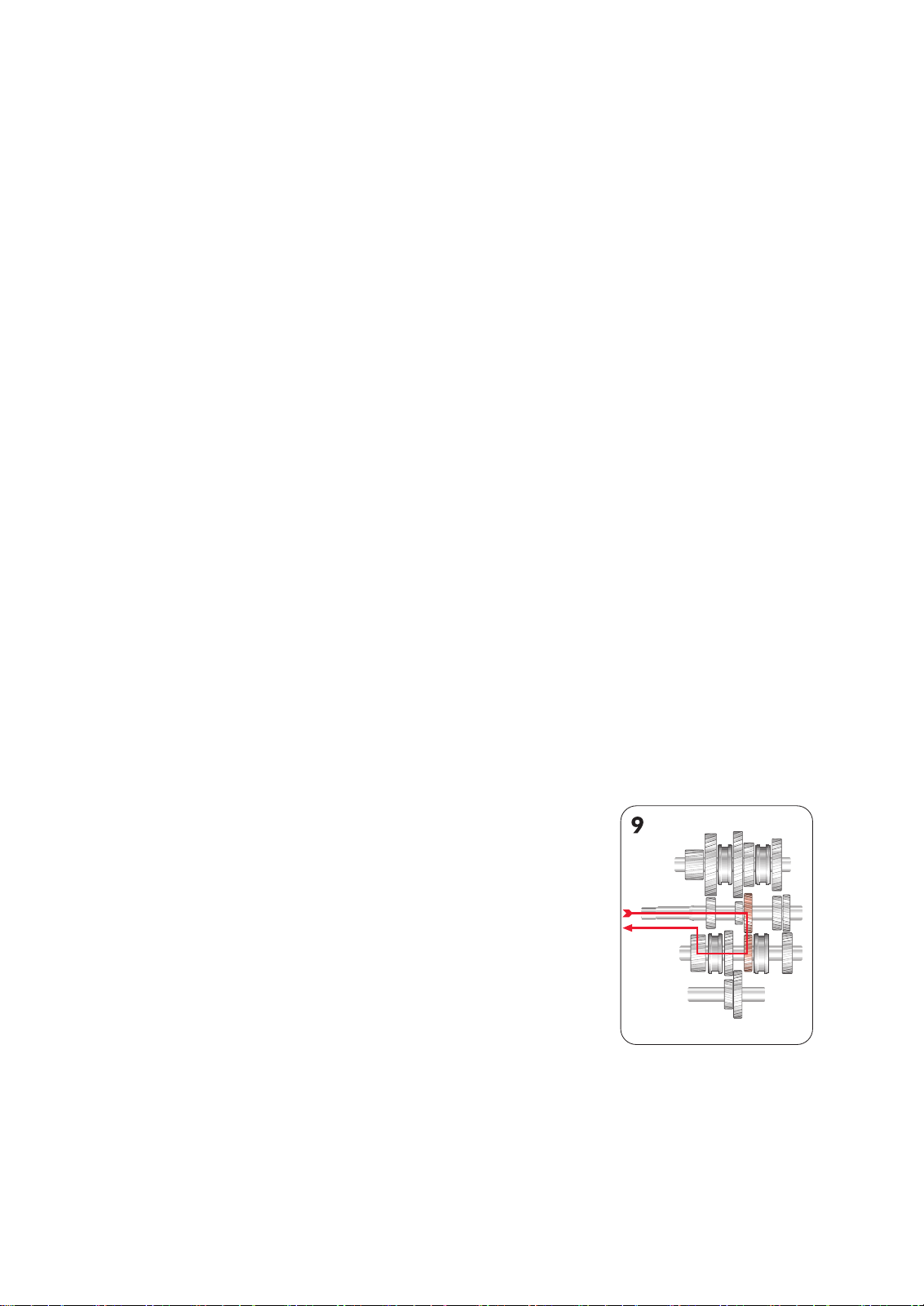
4.
TW2: 5., 6th gear and reverse
3. TW1: 1st, 2nd, 3rd and 4th gear
output shaft.
2. Because installation length is saved by using two short output shafts in comparison with only one long
1. a, c
Solutions:
27
Page 28
205
For internal use only © VOLKSWAGEN AG, Wolfsburg
All rights reserved. Technical specifications subject to change without notice.
840.2810.24.20 Technical status: 09/98
❀ This paper is produced from
non-chlorine-bleached pulp.
 Loading...