

Audi Q7 361, Q7 Service
Serv
ice Training
Audi Q7
Self-study
programme 361
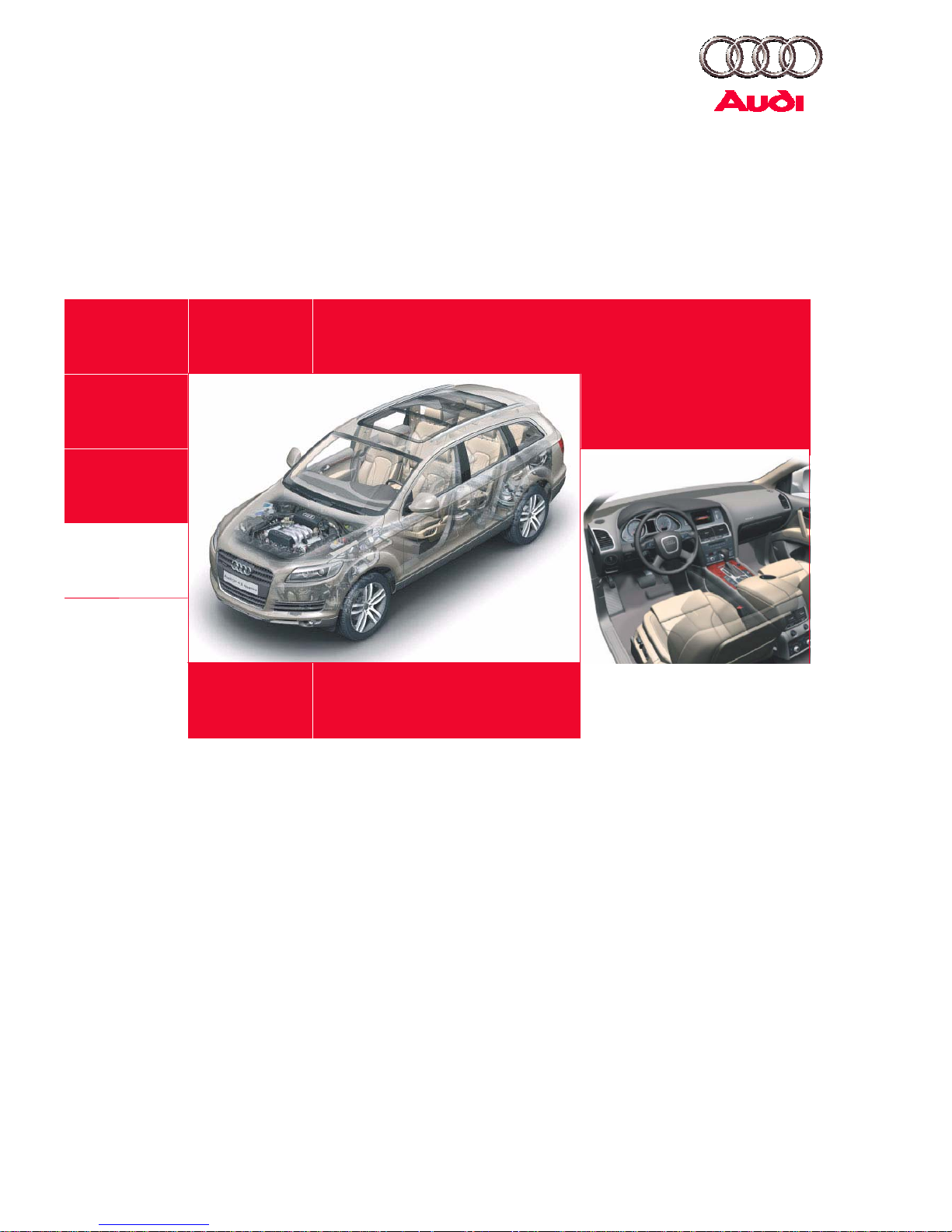
The Audi Q7
In
superior fashion, the Audi Q7 c
ombines
spor
tiness and versatility,
advanced tec
hnology
and
pr
emium-class
luxury.
On the road, it ex
cels with the driving performance
and dy
namics of
a
sports car, while redefi
ning the
possibilities of
its class off-road. A vehicle which
visually display all its qualities and meets its
promise in
tec
hnological
terms, on any road and
under any
conditio
ns.
Audi Q7 – the hi
gh-perf
ormance SUV from the
creator of qua
ttro.
The
very design of the Audi Q7 sets new standards.
Char
acteristic of the typical Audi dynamism are the
swooping cu
rve of the roof
line and the distinctiv
e
rela
tionship between the high wa
istline and narrow
window ar
ea. The
dynamic sweep of the fr
ont se
ction
and
the powerful rear
with the sharply sloping D
-
pillars pr
ovide
a coupe-like profile.
Equally charac
teri
stic elem
ents of the current Audi
styling are the shoulder line and
dyna
mic line which
define the
side section.
361_0
00
Taking the le
ad: With
de
sign & performa
nce
Contents
Intr
oduction . . . . . . . . . . . . . . . . . . . . . . . . . . . . . . . . . . . . . .
4
Body . . . . . . . . . . . . . . . . . . . . . . . . . . . . . . . . . . . . . . . . . . . .
8
Passenger protection
. . . . . . . . . . . . . . . . . . . . . . . . . . . . . 12
Engine . . . . . . . . . . . . . . . . . . . . . . . . . . . . . . . . . . . . . . . . . . 34
Running gear. . . . . . . . . . . . . . . . . . . . . . . . . . . . . . . . . . . . 44
Electric
al system . . . . . . . . . . . . . . . . . . . . . . . . . . . . . . . . . 50
Air conditioning
system . . . . . . . . . . . . . . . . . . . . . . . . . . 54
Infotainment
. . . . . . . . . . . . . . . . . . . . . . . . . . . . . . . . . . . . 68
The se
lf-s
tudy programme provides ba
sic informat
ion on the
design
and fu
nction of
new vehicle models,
new vehicle compon
ents or new technologi
es.
The self-study programme is not
intended as a workshop manual.
The spe
cified values only serve for better underst
anding and relate to the so
ftware versions
applicable at the time the SSP was com
piled.
For maintenance
and repair
oper
ations it is
essential
that you refer to the current technical li
terature.
Note
Note
Intr
oduction
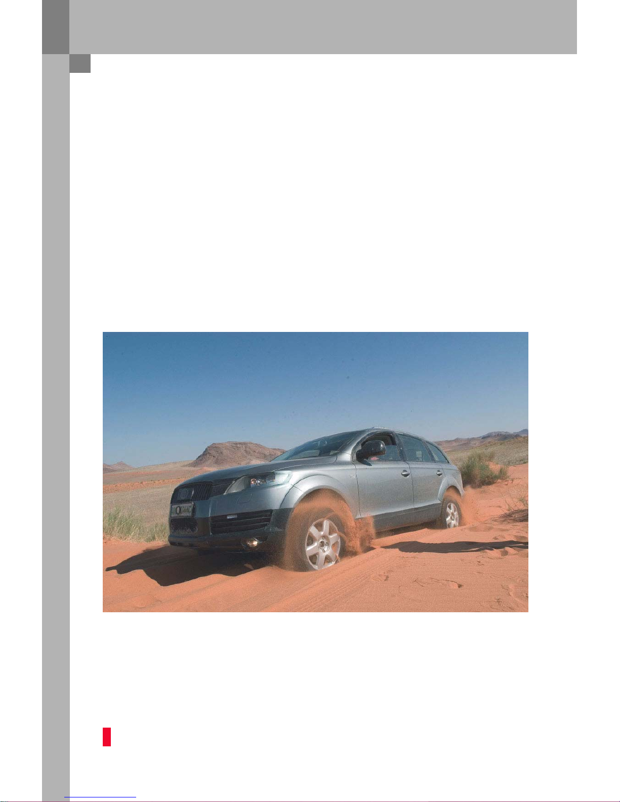
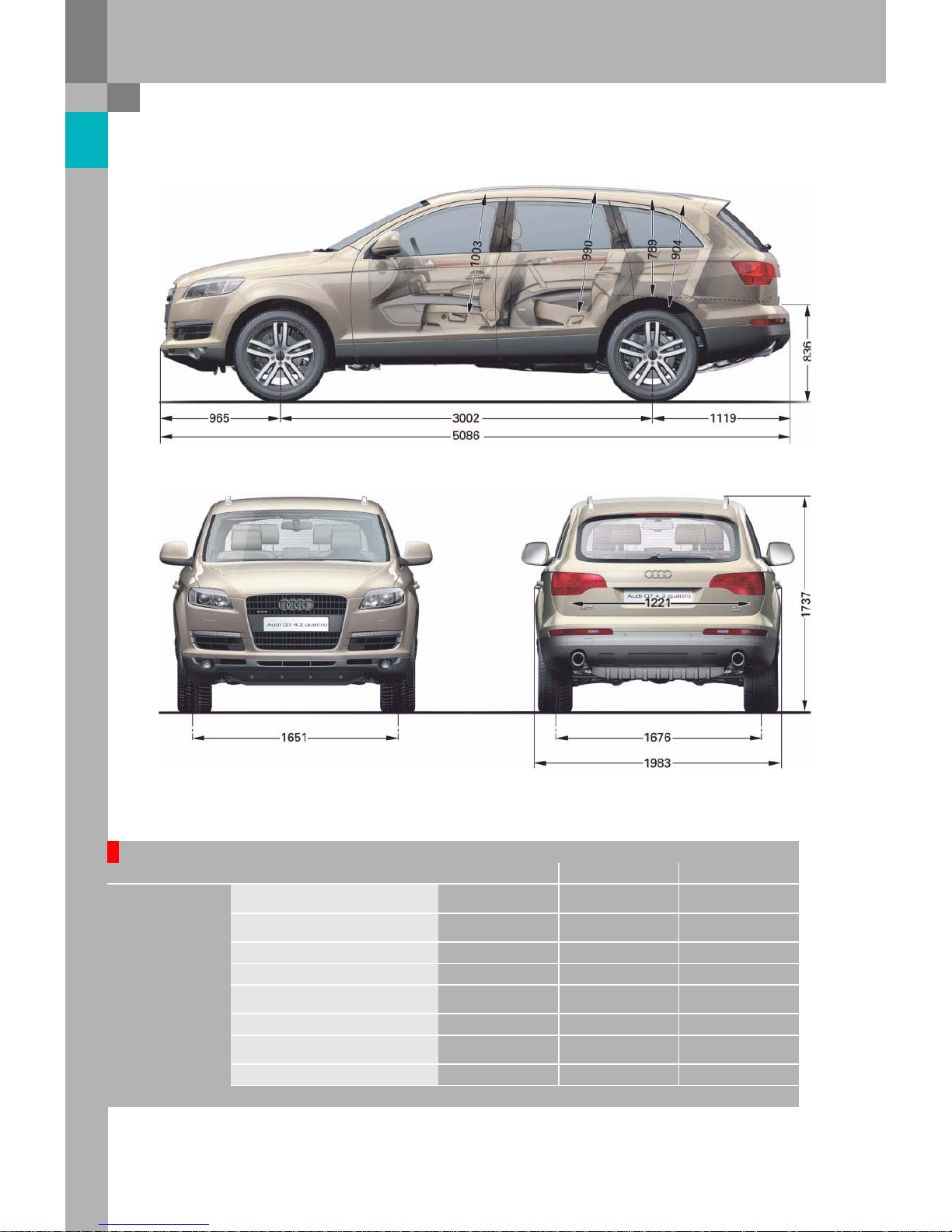
In a nutshell
Some Audi Q7 dimensions.
361_045
361_046
5-seater
6/7-seater
Admiss
ible total weight in kg
4.2l FSI
3.0l TDI
Unla
den weight
without dr
iver in kg
4.2l FSI
3.0l TDI
Drag coeffi
cient Cw
0.37
2895
2950
2240
2295
3065
3120
2270
2325
Tank capacity
in
litres 100
Tra
iler weight, braked
(on 12 %
uph
ill
gradient)
in kg
3500 3200
Nose we
ight
in kg 140 130
Combinat
ion weight (12 %) in kg
4.2l FSI
3.0l TDI
Admiss
ible roof
load in kg
100
6495
6550
6365
6420
4
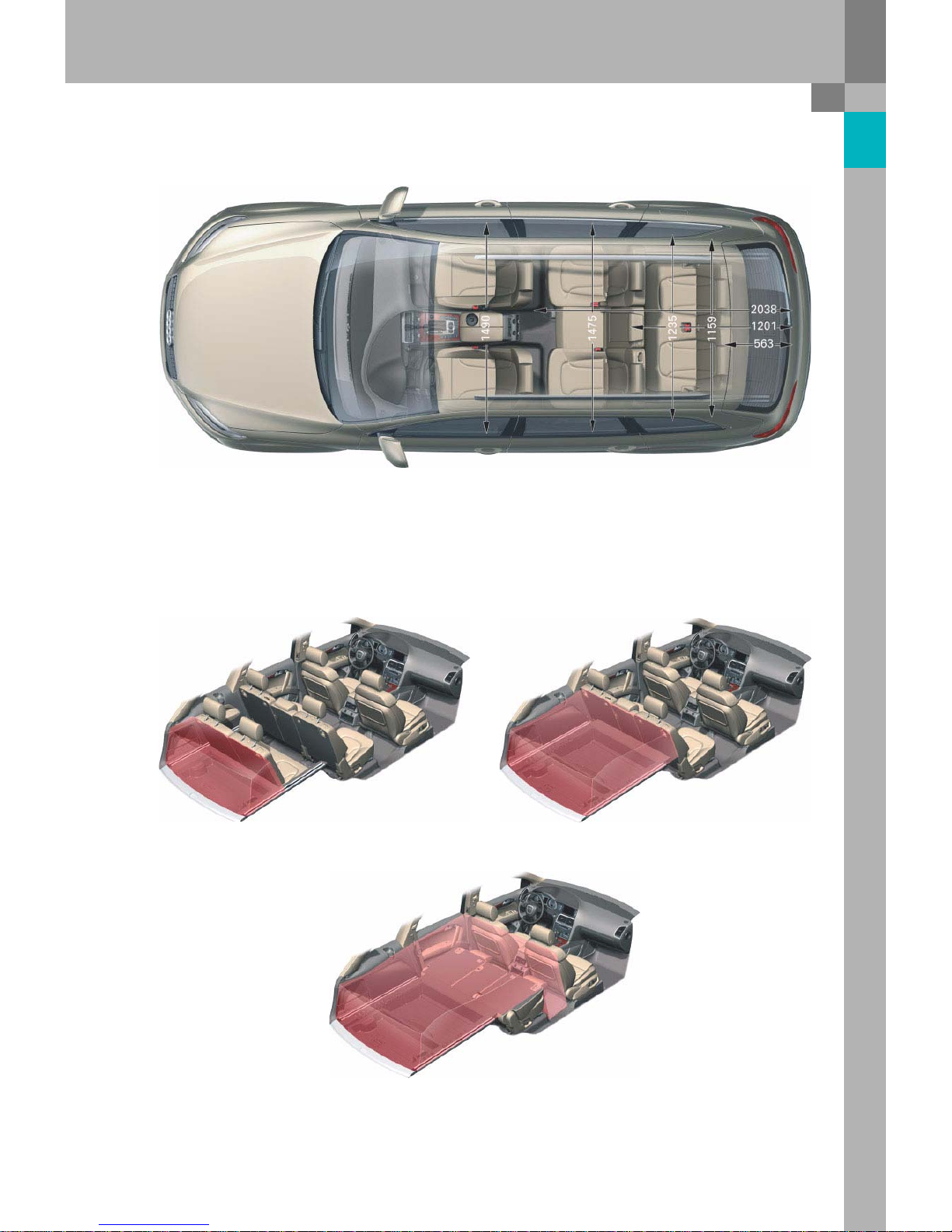
Interior dimensions
361_103
Luggage
compartment volume
775 l
330 l
36
1_105
361
_
104
2035 l
361_10
6
5
Intr
oduction
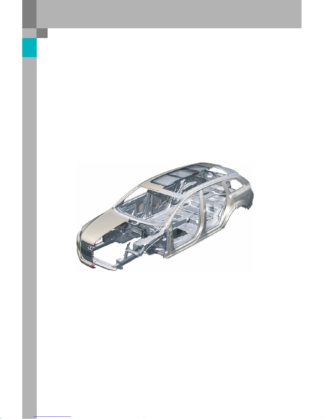
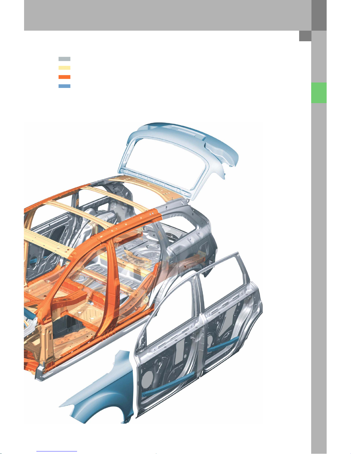
Body
The
body of the Audi Q7 has
been newly developed by Audi and is
not ba
sed on
a predecessor SUV model.
During
the deve
lopment proce
ss, the most signif
icant pr
operties and characteristic
values were initia
lly
defined. For ex
ample:
●
body weight
●
t
orsional and bending values
●
crash
perf
ormance
●
sche
duled development time
●
scope of simulation and protot
ype devel
opment
●
planned insurance ca
teg
ory
Significant features of the Audi Q7 body shell ar
e a
high ov
erall
rigidity as well as optimised local bending and
torsional
va
lues at the body nodes and fo
rce application ar
eas.
Bodys
hell
361_055
The development
●
of an open sky system,
●
an optional third seat row,
●
a
tailgate with integr
ated rear
lights, which wraps
around to the rear side panel,
were furt
her i
mportant features.
The fo
cus was on
combining these elements
with
the typical Audi high quality expressed, for instan
ce,
in the dimens
ional accuracy of the body parts,
the
narrow
gap widths and
surface finish.
The
self-su
pporting, lightwei
ght steel body of
the
Audi Q7 is built in four bodyshell versions:
●
Normal roof
●
Normal roof with three seat rows
●
Panorama roof (open sky system)
●
Panorama roof (open sky system) with thr
ee
seat
rows
The Audi Q7
with thr
ee
seat rows is eq
uipped with
an
additional cross-
piece in the spare wheel well
ar
ea for
attac
hment of the seat belts. On
the
ve
rsions with the panorama roof, the cr
oss-
pieces at
the B and C-pillars are dispensed with. T
heir
function is fulfilled by the open sky mo
dule.
6
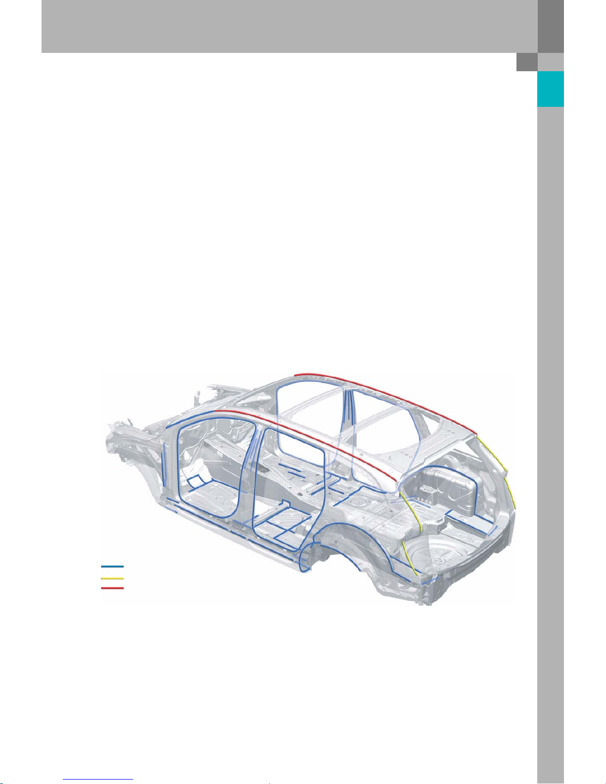
Joining tec
hniq
ues
In
order to
meet the high demands
with regard to
body rigidity, crash safety and optimised pr
oduction
pr
ocesses, the following joining techniques ar
e
employed on the Audi Q7:
–
Spot welding
–
Spot weld bonding
–
MAG welding
–
Laser soldering
–
Pla
smatron soldering
The
joining technique
most frequently employed for
areas subject to
high loads is
spot weld bonding
using
a
structural
adhesive.
The
bonded jo
ints, with
a
length of 79815
mm,
co
mprise
5403
spot welds. The to
tal length of
the
la
ser-soldered
joints (s
eamless joints between roof
and side frame) amou
nts to 4420
mm. As with the
Audi A3 Sportback
and the Audi A6 Avant '05, the
side pa
nel and the rain channel are joined using
plasmatron
soldering. Like la
ser soldering, this
tech
nique
ensures
a hi
gh-q
uality and
a
virtually
invisible seam. The
length of the left and right joints
amounts to 1438
mm. The
length of the MAG
welded jo
ints, used in areas which are inaccessible
using welding tongs, amounts to 15272
mm.
Adhesive
Plasmatron soldering
La
ser soldering
Spot welding (not sh
own)
MAG
welding (not shown)
361_057
7
Body
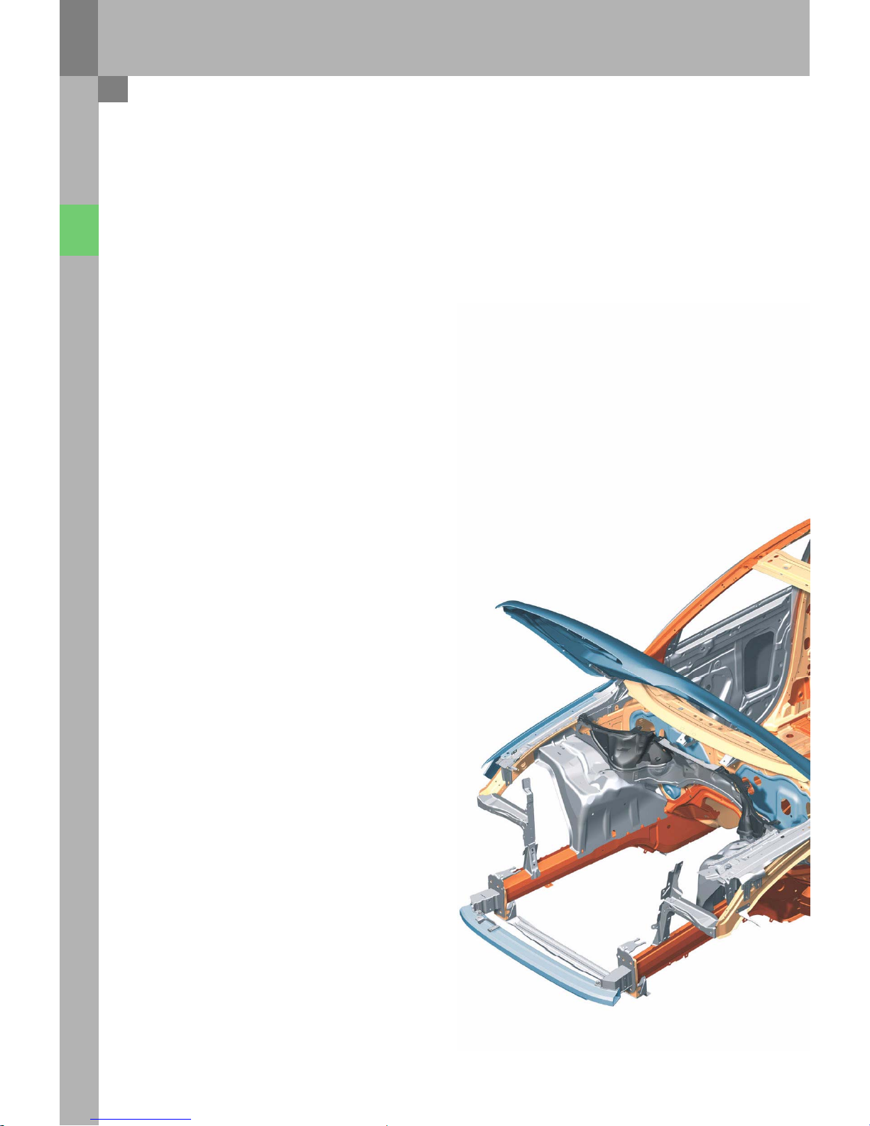
Materials
In
addition to
the joining techniques employed,
selection of the correct materials is vital for
ac
hieving both crash
safety and body rigidity.
Depending on loading and weig
ht, the most
suitable material is
deter
mined for each
component.
The propor
tions of the individual
materials used ar
e
as
follows:
–
Standard steels
36 %
–
High-strength steels
26 %
–
Higher-strength and
super high-strength steels
32
%
–
Aluminium 6%
The
wing panels, bonnet and
tailgate are made of
aluminium, making them some
22
kilogr
ammes
lighter than their
steel counterpar
ts. The
weight was
further reduced through the use of various semifinished pr
oducts*. With ta
ilored ro
lled blan
ks, for
example,
the wall thic
kne
sses can be adapted to
withstand differing component load
ing. Th
e
reinf
orcements for the rear longitudinal members
and the floor
cover pa
nel are made from
tailored
rolled
blanks.
* Semi-f
inished pr
oducts: Pre-processed materials
for the manufacture of parts and components
The
sill tube consists of
a ro
lled section because the
manufacturing tolerances are lo
wer in this case
than for an ex
truded tube, enabling smaller wall
thic
knesses. In order to meet pedestrian pr
otection
requir
ements, plastic parts are used in the ple
num
chamber/bulk
head area.
8
Stan
dard steels
High strength
steels
Higher-strength and super high-strength steels
Aluminium
361_0
56
9
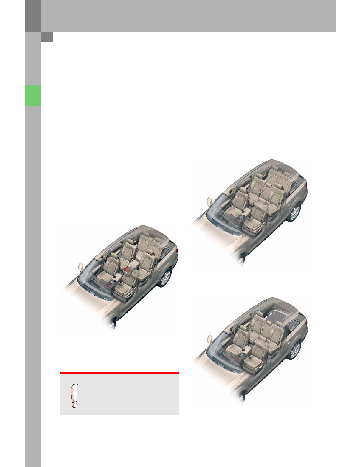
Body
Seat
concept
The Audi Q7 seats up to se
ven occupants. As
standard, the Audi Q7 is eq
uipped with five seats.
The Audi Q7 can optionally be fitted with el
ectrically-adjustable seats for the driver and fr
ont pa
ssenger.
A memory function is also available for the front
seats. The backrests of the driver and front passenger seats
have been ergono
mically designed
such as to reduce to
distance between the occupant's head and the head
restraint. The headrest must be adjusted correctly for
this purpose. The seats in the second seat row can be
individually adjusted long
itu
dinally and offer
occupants the most generous leg room in this
vehicle cla
ss. Wher
e
the Audi Q7 is eq
uipped with
a
third seat row, the
second
seat row features an easy-e
ntry func
tion and
longit
udinal
seat adju
stment. In the 6-
seater equi
pment version, comfort
seats are optionally availa
ble for the
second seat row.
Audi Q7 with seven seats
Audi Q7 with six se
ats
361_050
Audi Q7 with
five se
ats
36
1_052
Note
Please refer to the owner's ma
nual for
inf
ormation on operation of
the
vehicle seats.
361_049
10
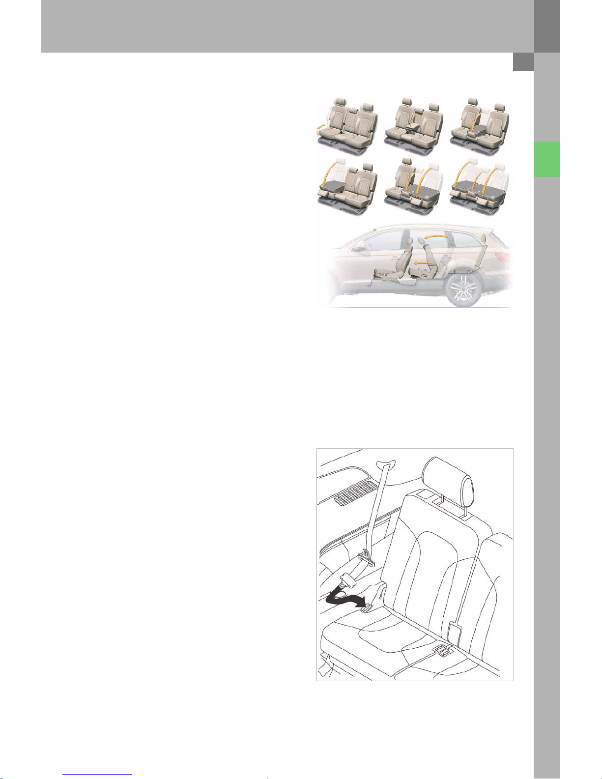
The
head restraints of the second seat row do not
pr
event the backrests from fo
lding.
When the head
restraints of the second seat row are lowered, the
backrests do not fully reach
the load floor position.
When folding down the backrests of the third seat
row, the head restraints lower automatically, making
it
ea
sier to fold
down the backrests.
If
the seats in the second and third seat roads are
unoccupied, the head restraints can be lowered by
hand in or
der to impr
ove rearward visi
bility.
The easy-e
ntry func
tion on the second seat row is
operated vi
a a le
ver next to the head restraint. The
backrest folds forwards to
a
certain angle. The seat
base
also moves in the direction of tr
avel. The easy-
en
try function enables the occupants to
enter and
exit the third
seat row.
361_051
Attac
hment of the seat belts to
the seats of the third
sea
t row is ac
hieved via
additional belt buckle
s. Th
e
advantage is that the seatbelts can be removed
from
the seats as requir
ed. The
seat belts ar
e
retracted and the latch plates can be inserted in th
e
D-pillar tr
im. In
this manner,
the seat belts ar
e
pr
otected ag
ainst damage during loading of the
luggage c
ompar
tment
when the backre
sts ar
e
folded down. The central belt bu
ckles ar
e a
ttached
to
the vehicle floor.
Persons above
a
height of
160 cm are prohibited
from
being
seated in the third seat row.
361_044
11

Passenger pr
otection
Passenger pr
otection in the A
udi Q7
Owing to
its wide range of use, the Audi Q7 repr
esen
ted
a
special challenge for the development team:
A high degr
ee of passe
nger protec
tion du
ring both
on-road and off-road oper
ation.
In
meeting these requir
ements, the Audi Q7 fits seamlessly
into
the high safety
level of the current Audi
model
range.
The passenger pr
otection system of the Audi Q7
comprises the following components and systems:
–
Airbag control unit
–
Driver and fr
ont passenger airbag, dual
stage
–
Front side airbags
–
Sideguards (curtain airbags)
–
Crash sensors for front airbag, the so-c
alled upfront sensors for fr
ontal impact detection
–
Crash sensors at the B-pillars for side impact detection
–
Crash sensors at the C-pillars for side impact detection
–
Front belt
tensioners
–
Ba
ttery isolation igniter
–
Switch in fron
t-seat belt buckles
–
Seat occupied sensor in front pa
ssenger seat
Side airbags for
the second seat row and
a key operated
switch for deactivation of the fr
ont passenger airbag
with the corre
sponding warning lamp are also availa
ble as optional equipment.
Owing to
the
va
rious requir
ements and statut
ory regulations placed upon vehicle
manufactur
ers by the
markets, the eq
uipment versions may vary, part
icularly with regard to
the US market.
Key
E24 D
river side belt switch
E25 Front pa
ssenger
side belt switch
E22
4 Key
oper
ated switch to de
activate fr
ont
pa
sse
nger side airbag
G128 Seat occupied sensor, front passenger side
G179 Side airbag crash sensor on driver side
(B-pillar)
G180 Side airbag crash sensor on front pa
ssenger
side (B-pillar)
G256 Rear
side airbag crash sensor on dr
iver side
(C-pi
llar)
G257 Rear side airbag crash sensor on pa
ssenger
side (C-pillar)
12
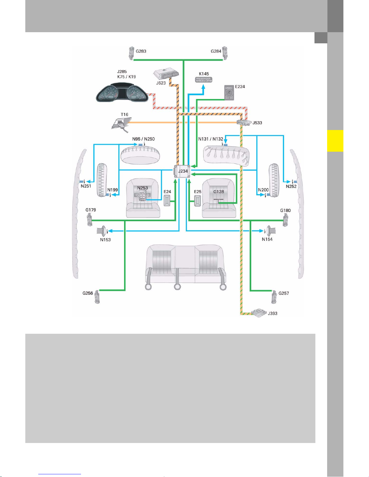
361_001
G28
3 Front
airbag crash sensor for driver
side
(front end, left)
G28
4 Front airbag crash
sensor for front passenger
side (front end, right)
J234
Airbag control unit
J285
Control unit in dash pa
nel insert
J393
Conven
ience
system central control unit
J533 Data
bus diagnostic interface (g
ateway)
J623
Engine co
ntrol unit
K19 Seat belt
warning
system
warning lamp
K75 A
irbag wa
rning lamp
K1
45 Front passenger side airbag de
activated
warning lamp (PASSENGER AI
RBAG OFF)
N95
Driver side ai
rbag
igniter
N
250 Driver side airbag igni
ter
2
N131 Fr
ont passenger
side airbag igniter
1
N132 Fr
ont passenger
side airbag igniter
2
N153 Driver
seat belt tensioner ig
niter
1
N154 Fr
ont passenger
seat belt
tensioner ig
niter
1
N199 Side airbag
igniter on driver side
N200 Side airbag igniter on front pa
ssenger side
N
251 Driver side curtain airbag igni
ter
N252 Fr
ont passenger
side curtain airbag igniter
N253 Battery
isolat
ion igniter
T16 C
onnector, 16-pin (diag
nostic connection)
13
Passenger pr
otection
Airbag control
unit J234
The
purpose of the electronics integrated in
the airbag control unit is to
detect
vehicle deceleration or
a
cceleration and to evaluate it so as to
detect
a
vehicle
impact. In order to
detect vehicle deceleration or
a
cceleration during an impact, ex
ternal
sensors are used in
addition to
the sensors
instal
led inside the control
unit. The
electronics in the control unit
detect
a crash based al
one on the info
rmation received from
the sensors.
O
nly once all the sensor information has been evaluated by the co
ntrol unit electronics can the electronics
decide when and which safety components should be
activated.
The airbag co
ntrol unit is able to
detect frontal,
side and rear impacts.
A further task of
the airbag control unit is to
activate the relevant restraint systems (belt tensioners or belt
tensio
ners
and airb
ag) depending on the type and se
verity of
the impact as well as signalling the crash to
other vehicle systems.
The
airbag electronics have the following main
ta
sks:
–
Crash detection (front, side, rear)
–
Defined trig
gering of the belt tensione
rs, airbags
and battery isolation igniter
–
Defined triggering of the second fr
ont ai
rbag
stage
–
Eva
luation of all input information
–
Perma
nent monitoring of the complete
airbag
system
–
Independent
power supply via
a ca
pacitor for
a
defined time (approx. 150
ms)
–
Fault display via a failure
warning lamp
–
Storage of fault and crash information
–
Communication of a crash to
the other system
components via the drive CAN or discrete crash
output (conventional wiring)
–
Activation of seat
belt warning system
361_007
For inf
ormation on
which components must be replaced following an accident, please refer to the applicable
W
ork
shop
Manual in ELSA. An airbag co
ntrol unit can o
nly be repl
aced with
the aid of an online-capable VAS
5051
or VAS
5052. The guided fault-finding or guided function
applications must be used for this
purpose. The
airbag control unit must be c
oded and adapted to the re
levant vehicle. If
coding or adaption is not performed
correctly,
this may re
sult in
malfunctions in other vehicle systems,
e.g. the ESP.
14

Data exchange
The
airbag control unit is connected to
the drive CAN.
The airbag
control unit transmits the following inf
ormation
via the dr
ive CAN:
–
Activation of wa
rning lamp K7
5
–
Activation of seat
belt warning system
–
Diagnostic data
–
Crash signal
–
Crash inf
ormation for the control element test
–
ESP data
–
Front passenger airbag activated/deac
tivated status (display in dash panel insert)
The airbag
control unit
evaluates the follow
ing information from the data
bus:
–
Dimming for the fr
ont passenger side airbag de
activated warning lamp (Passenger Airbag Off)
The
information
that a crash has occurred is
used by ot
her control un
its in or
der to u
nlock a locked central
locking system, cut off
the fuel supply,
activate the hazard warning lights
etc.
Ai
rbag warning lamp
K75
Activation of the airbag warning lamp, which is loca
ted in the dash panel insert J285, is
performed via the
CAN bus. In
the absence of a
data message from the airbag control un
it, the warning
lamp is switched on
auto
matically by the dash panel insert.
Rear impact re
cognition
During a rear
impa
ct, the vehicle is strongly a
ccelerated in the direction of trav
el. The crash sensors in the
ai
rbag co
ntrol unit and the crash
sensors G283
and G
284 de
tect this
vehicle acceleration and tr
ansmit
the
rel
evant signals to the airbag electronic
s. Th
e airbag electronics evaluate the information. If
the sensor
sign
als ex
ceed
a
specified
va
lue, the belt tensioners are trig
gered and the battery
isolation igniter is activated.
15
Passenger pr
otection
Seat
belt warning system
The Audi Q7, like the Audi A6 ´
05 for example, features a seat belt warning function for the driver and front
pa
sse
nger.
When the ignition is switched on, the airbag control unit evaluates the info
rmation from
the driver and fr
ont
pa
ssenger belt buckle switches as
well as information from
the fr
ont passenger side seat oc
cupied sensor.
The
airbag control unit de
tects wh
ether the fr
ont passenger
seat is oc
cupied or not ba
sed on the resistance
values of the fr
ont passenger side seat oc
cupied sensor. If
the driver or fr
ont passenger
have not fastened their
seat be
lts, they are aler
ted via the
seat
belt warning sy
stem wa
rning lamp K19 in the dash pa
nel insert and an
a
udible signal.
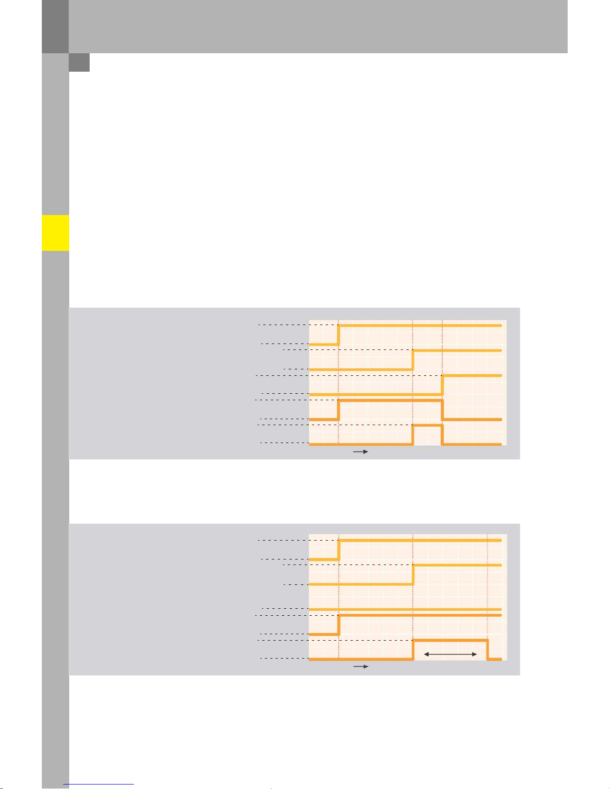
Timing di
agrams for the seat belt
warning system
Visual and audible signals –
seat
belts are fastened
late
Terminal 15
Vehi
cle speed
Fasten
ed
Seat belt warning sy
stem warning lamp
On
Off
v >
10 km/h
v <
10 km/h
Yes
No
On
Aud
ible signal
Off
On
Off
Time
361_016
Visual and audible signals –
seat
belts not fastened
Terminal 15
Vehi
cle speed
On
Off
v >
10 km/h
v <
10 km/h
Fasten
ed
No
On
Seat belt warning sy
stem warning lamp
Aud
ible signal
Off
On
Off
Time
min.
90
sec.
361_018
The
warn
ing is re
activa
ted if the seat
belt
sta
tus changes du
ring "termi
nal
15
on".
16
Seat
occupied sensor, fr
ont passenger side G128
The front passenger side seat
occupied sensor
consists of a plastic film
inco
rporating several
individual pr
essure sensors. The front passe
nger
side seat occupied sensor is located in the fr
ont
pa
sse
nger seat, between the seat cover and
padding. The seat occupied sensor ex
tends
across
the rear part of the fr
ont passenger seat and is
positioned such that the relevant ar
ea of the seat
surface is monitored.
Depending on the lo
ad, the resistance
value of the
fr
ont pa
ssenger
side seat occupied sensor is
modified. When the fr
ont passenger seat is
not
occupied, the resistance value of the fr
ont
pa
sse
nger side
seat occupied sensor G128 is high.
As the load incr
eases, the re
sistance value falls.
Above
a load of
appr
ox.
5 kg,
the airbag control unit
detects "seat occu
pied".
The airbag
control unit requires the
information
from
the front pa
ssenger
seat occupied sensor G128
and from the belt buckle switches for
the seat
belt
warning system.
361_017
Resistance va
lue of G1
28
Evaluation
approx. 430 Ohm and high
er
approx. 140 Ohm and lowe
r
Seat not occupied
Seat occu
pied
17
Passenger pr
otection
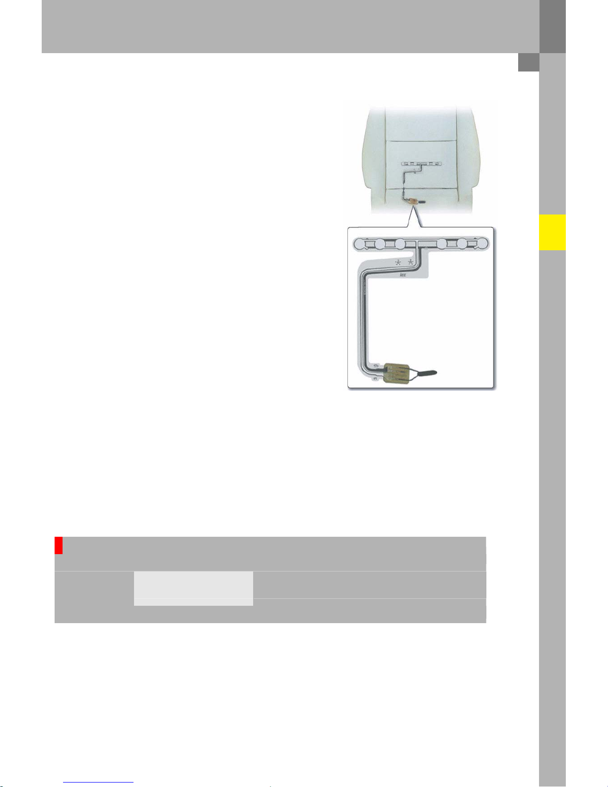
Belt switch
Driv
er
side belt switch
E24
Fr
ont passenger side belt switch E25
(In the
driver and front passenger side belt buc
kles)
Information as to
whether or not the driver and fr
ont
pa
sse
nger have fastened their seat belts is required
by the "seat belt warning system" function. In order
for the ai
rbag
control unit to receive this informat
ion,
the belt switches
E24 and E25 are integr
ated in th
e
belt buckles for the front
seats.
The
switches fi
tted are r
eed switch
es. The reed
switches
switch from
"switch open" to
"switch
closed" through the action of an external magnetic
field. The magnet
1 in
the so-called spring
thorn is
located near the r
eed switch when
the latch plate is
not in
serted, i.e. the r
eed switch is closed.
When the latch plate is inserted in the belt buckle,
the spring thorn is moved.
The
mag
net
1 in
the spring thorn no l
onger acts
upon the r
eed switch,
i.e. the r
eed switch is open.
Based on the measured re
sistance value, the airbag
control unit recognises wh
ether the seat belt is
fastened or not.
361_019
Spring thorn
Spring
thorn
Reed switch
Spring
thorn
Reed sw
itch
3
61_020
3
61_021
36
1_034
Magnet I
361_041
36
1_040
18
Driv
er seat belt
tensioner igniter 1 - N153
Fr
ont passenger seat belt tensioner
igniter 1 - N154
The front seats of
the Audi Q7 is eq
uipped with the
pr
oven compact tensio
ners. The
belt tensioners
work a
cco
rding to
the "ball
gear" principle
(not
USA)
and are
triggered
electrically by
the airbag control
unit. During a crash, the belt tensio
ners ar
e
activated before the fr
ont airbags. To prevent
excessive loads to the occupants,
the belt r
eels ar
e
eq
uipped with belt force limiters. Above
a
specified
load
level, th
ese force limiters slacken the belt,
allowing the occupant to move forwards into
the
already deployed airbag.
In
the event of
a
side impact with
side ai
rbag
trig
gering, the relevant belt tensioner is also
trig
gered. In the event of a rear
impact, the belt
tensioners are also activated, depending on the
seve
rity of the impact.
Seat belt
361_053
Key oper
ated switch to
deactivate front passenger side
airbag
E224
The
key oper
ated
switch to deactivate fr
ont
pa
sse
nger airbag
E224 and the corre
sponding fr
ont
pa
sse
nger side airbag de
activated warning lamp
K
145 (PASSENGER AIRBAG
OFF) are required in
order to
deactivate the fr
ont passenger airbag. An
illuminated fr
ont passenger side airbag
deac
tivated
warning lamp K145 (P
ASSENGER AIRBAG OFF)
indicates to the
occupants that the front
passenger
airbag is
deac
tiva
ted.
The
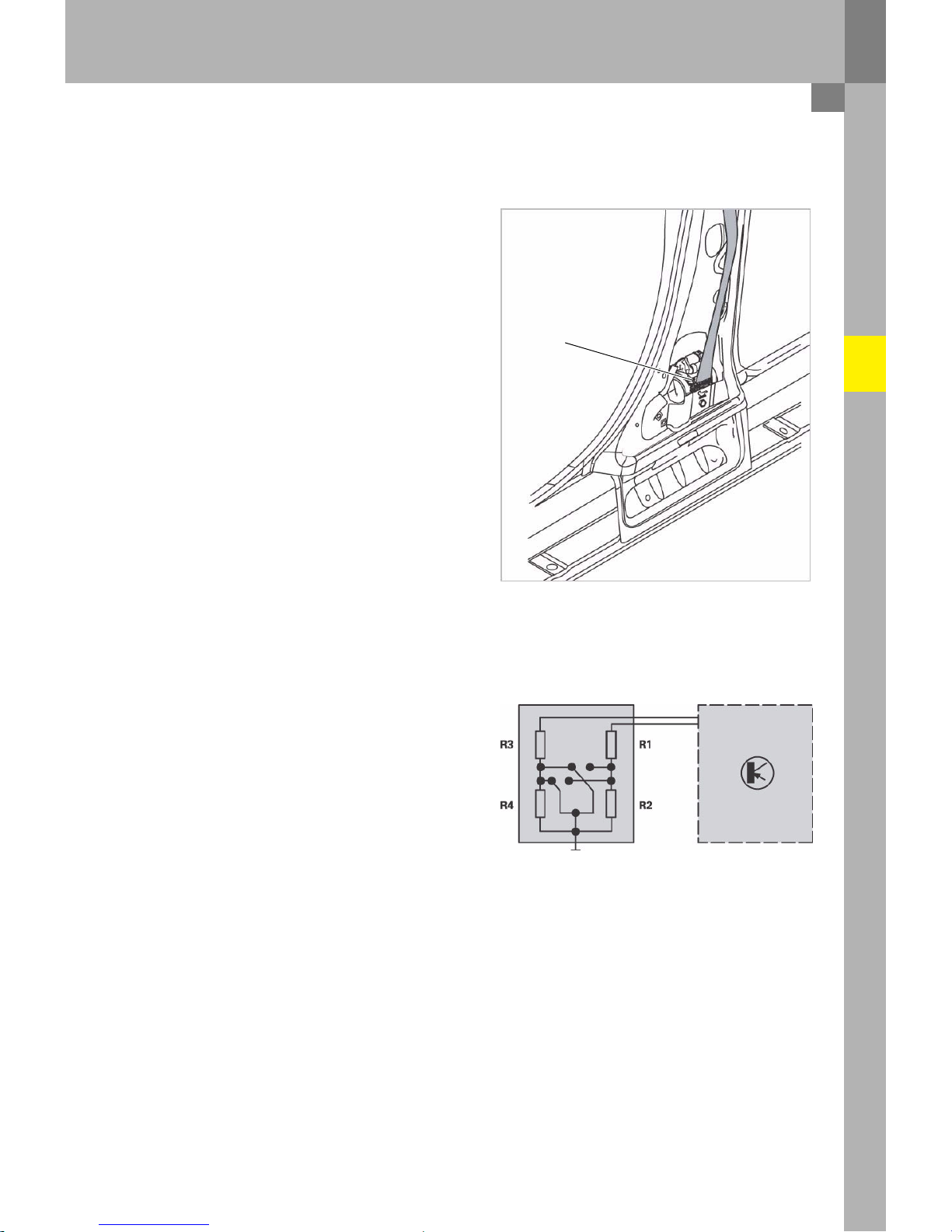
control unit unequivocally recognises the
switch position by means of the arra
ngement of
four resist
ors which are connected in-line,
pair
-wise.
If
the airbag
control unit detects
a fa
ulty key
oper
ated switch, a fa
ult me
mory entry is made and
the fr
ont passenger side airbag
deac
tivated warning
lamp K145 (P
ASSENGER AIRBAG OFF)
begins to
flash.
Airbag control unit
J234
361_025
19

Passenger pr
otection
Airbag
The front airbags on the driver and fr
ont passenger sides are eq
uipped with tw
o-stage gas
generators.
Depending on the nature
and severity of the accident, the airbag control unit sets
a
time delay between the
two
ignitions (from approx. 5ms to 30
ms). The loads which the driver and fr
ont passenger are exposed to
during a crash can be reduced by means of a
delayed ignition of the pr
opellant charges.
Both pr
opellant charges are
ignited in all cases. This prevents
a pr
opellant charge from re
maining ac
tive
following
airbag deployme
nt.
Driv
er
airbag
N95 D
river
side airbag igniter I
N
250 Driver side ai
rbag
igni
ter II
The gas
generator in the driver ai
rbag works
using two
pyr
otec
hnic pr
opellant char
ges.
Priming charge
Housing
Cap
Metal filter
Propellant
charge I
Metal filter
Propellant charge I
Bores
Propellant charge II
Ig
niter I
Ig
niter II
361_014
The
driver's airbag gas generator is flexibly
mounted in
a rubber ring.
This minimises any
vibration at the steering wheel.
The gas generator acts as a vibration damper.
20
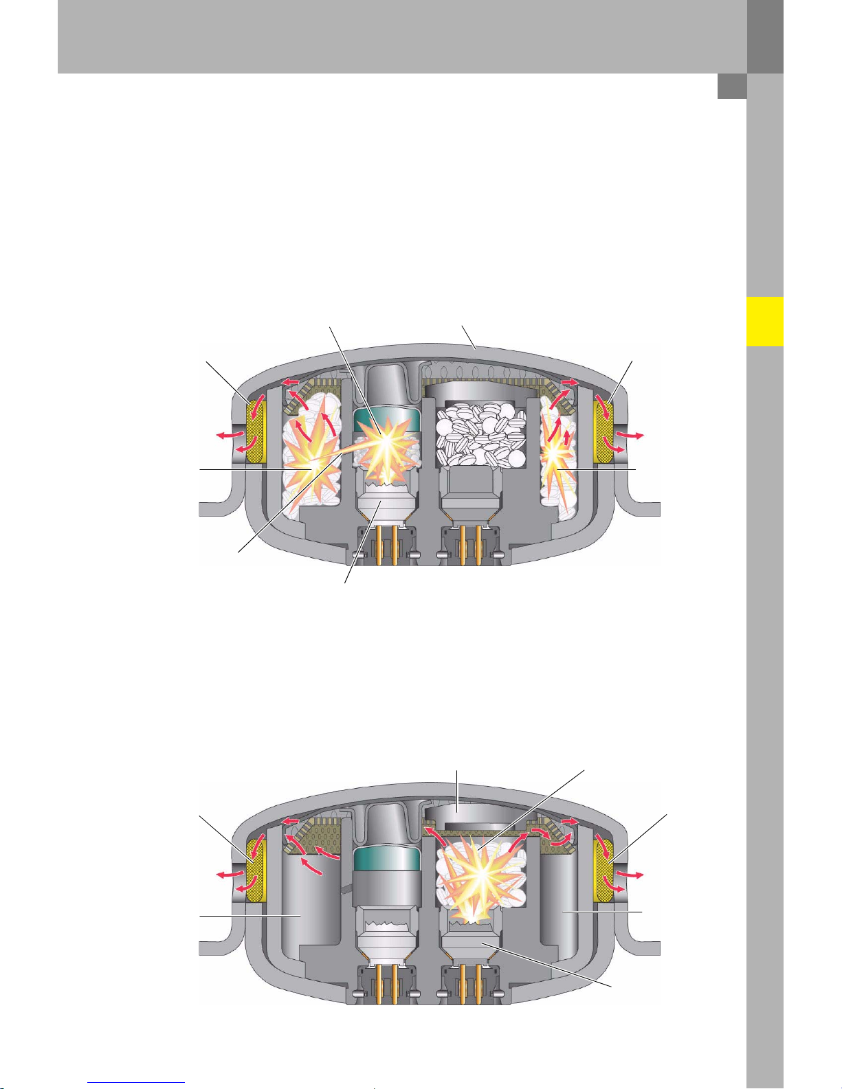
Driv
er
side airbag
igniter I - N95
The
electrical
igniter
I,
which is activated by the airbag control unit, igni
tes the priming charge I. This ig
nites the
actual pr
opellant charge I via the bor
es.
When the gas pressure generated thro
ugh co
mbustion of
the
pr
opellant ch
arge I ex
ceeds
a
specified threshold, the housing of the gas ge
nerator becomes def
ormed,
opening up a passage to the airbag via
the me
tal filter. The airbag is deployed.
Priming charge I
Housing
Metal filter
Propellant
charge I
Bores
Metal filter
Propellant charge I
361_015
Ig
niter I
Driv
er
side airbag
igniter II - N250
Following
a
defined delay,
the airbag control unit ener
gises
the second
electrical ig
niter,
which directly igni
tes the
second pr
opellant char
ge. At
a cert
ain pressure, the genera
ted gas
lifts up the cap of the second stage
and flows into
the airbag
via the combustion chamber of
the first stage.
Cap
Propellant ch
arge II
Metal filter
Combustion
chamber
Propellant charge I
Metal filter
Combustion
chamber
Propellant
charge I
Igniter II
361_013
21
Passenger pr
otection
Fr
ont passenger
airbag
N13
1 Front passenger side airbag igniter I
N13
2 Front passenger side airbag igniter II
The front pa
ssenger ai
rbag module h
ousing is made of plastic.
361_008
A two-stage hybrid gas generator is used on the pa
ssenger side. Two pyrotec
hnic propellant char
ges ar
e
contained in
a
compressed gas
cylinder,
which is activated
separately by the airbag
control unit. The
so-c
alled
cold gas in
the compressed gas
cylinder is
under
a pressure of approx.
250
bar and is
a
mixture of ar
gon
(approx. 98 %)
and helium (approx. 2
%). The airbag volume is
approx.
140
litres.
The
coil springs ensure that the propellant charge tablets are held in po
sition
(pretension).
Priming charge I
Propellant ch
arge I
C
oil spring
Filter
Ig
niter I
Ig
niter II
Priming charge II
Propellant charge II Coil spring
Burst disc
Compressed gas
cylinder
G
as: Arg
on, approx.
98 %
helium,
approx.
2 %
Pres
sure:
a
pprox.
250
bar
361_002
22
Fr
ont passenger side
airbag
igniter I - N131
The
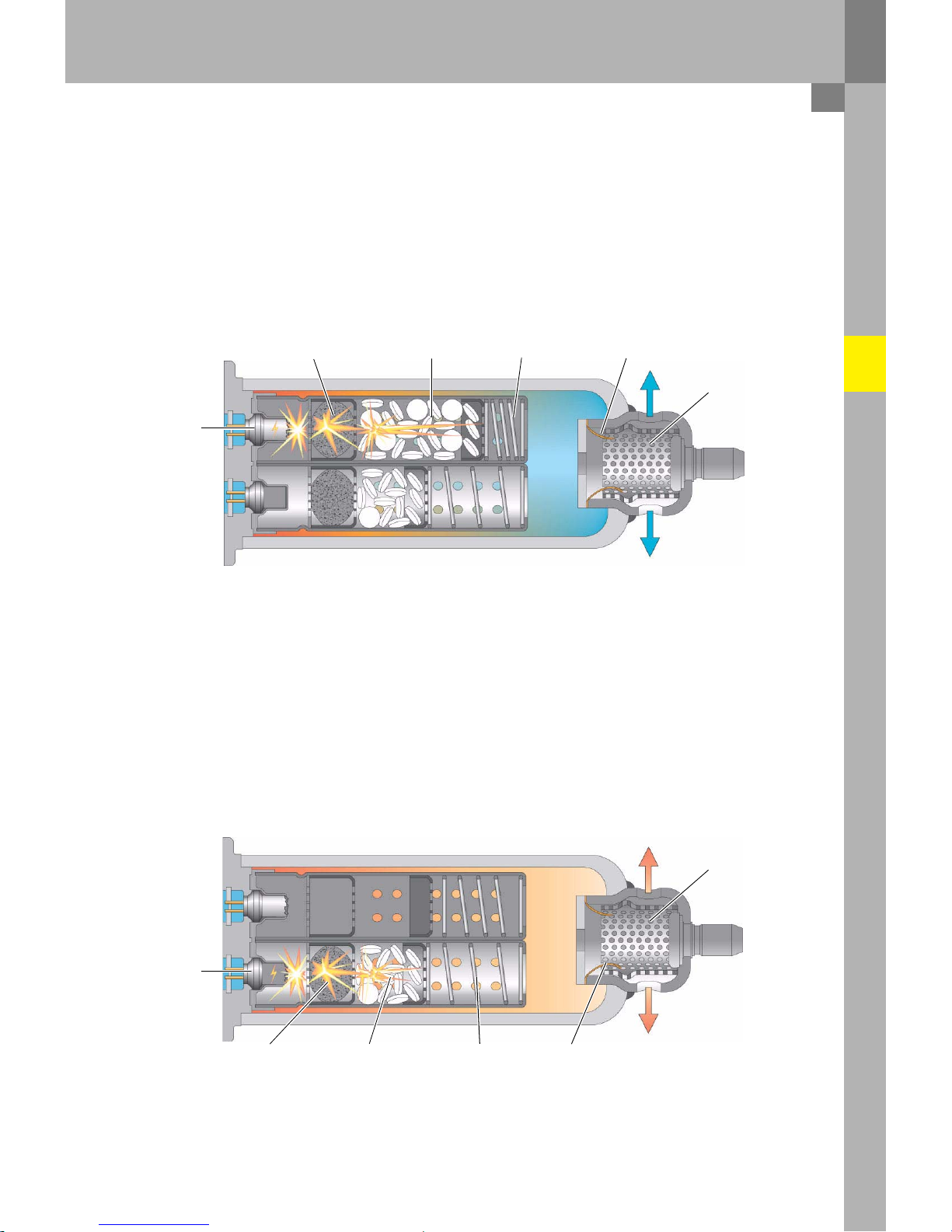
airbag control unit energizes the igniter I and the priming charge I is ignited. This in turn ignites the
actual pr
opellant charge I. The comb
ustion gas generated increases the pressure in the compressed gas
cylinder until the burst disc breaks at
a pre
determined pr
essure value. The gas
mixture reac
hes the airbag via
the metal filter and it is deployed.
Priming charge I
Propellant ch
arge I C
oil spring
Bu
rst disc
Filter
Ig
niter I
361_003
Fr
ont passenger side
airbag
igniter II - N132
The
oper
ating principle of the second stage is
identical to
that of the first. An additional vo
lume of gas is
supplied to
the airbag through co
mbustion of
the second propellant ch
arge. There is no
further increase in
pr
essure inside the airbag during the
second stage.
Filter
Ig
niter II
Priming charge II
Propellant charge II Coil spring
Burst disc
361_004
23
 Loading...