

Page 1
Service Training
The Audi Headlight Assist System
Self-Study Programme 434
Page 2
Introduction
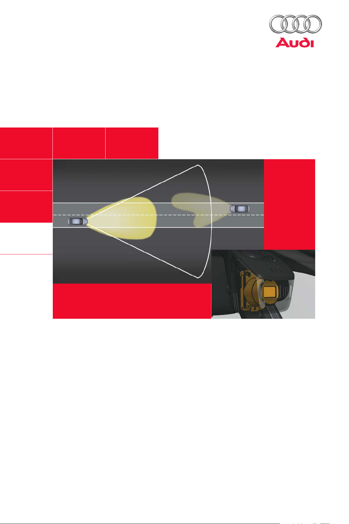
With the Headlight Assist System, AUDI has added a new highlight to its range of driver assist systems. The
system enhances ride comfort in the dark by automatically switching the main-beam headlights on or off
depending on the momentary traffic situation. Thus, it provides improved visibility while driving at night.
Surveys have shown that many drivers forgo switching on their main-beam headlights at night, even though
this would greatly improve visibility, and therefore safety, during night-time driving. Respondents cited, as
reasons, that under no circumstances do they want to dazzle oncoming traffic, or that they are familiar with
the route and therefore do not feel the need to use the main-beam headlights, or that they cannot be bothered
switching the main-beam headlights on and off all the time due to heavy oncoming traffic.
However, the visibility of objects is greatly reduced while driving with the headlights dipped, as opposed to
driving with the headlights on main beam. When driving with the headlights on main beam, objects can often
be detected well enough in advance for the driver to stop in time or take evasive action.
The Headlight Assist System maximises the "on" time of the main-beam headlights in the dark, and only dims
down when the ambient and traffic conditions necessitate. The main-beam headlights are dipped before they
can dazzle another road user. The driver has all the advantages of better-illuminated surroundings, without
having to constantly switch the main-beam headlights on and off by himself.
434_033
Page 3
Contents
Function description
The function of the Headlight Assist System . . . . . . . . . . . . . . . . . . . . . . . . . . . . . . 4
On and off conditions. . . . . . . . . . . . . . . . . . . . . . . . . . . . . . . . . . . . . . . . . . . . . . . . . . 5
Mode of operation of the Headlight Assist System
Introduction . . . . . . . . . . . . . . . . . . . . . . . . . . . . . . . . . . . . . . . . . . . . . . . . . . . . . . . . . . 6
An oncoming vehicle . . . . . . . . . . . . . . . . . . . . . . . . . . . . . . . . . . . . . . . . . . . . . . . . . . 7
A vehicle ahead . . . . . . . . . . . . . . . . . . . . . . . . . . . . . . . . . . . . . . . . . . . . . . . . . . . . . . . 8
Driving through a built-up area. . . . . . . . . . . . . . . . . . . . . . . . . . . . . . . . . . . . . . . . . . 9
A built-up area at a distance from the road . . . . . . . . . . . . . . . . . . . . . . . . . . . . . . 10
A single house by the roadside. . . . . . . . . . . . . . . . . . . . . . . . . . . . . . . . . . . . . . . . . 11
System operation and displays
System operation. . . . . . . . . . . . . . . . . . . . . . . . . . . . . . . . . . . . . . . . . . . . . . . . . . . . . 12
The operating logic of the Headlight Assist System . . . . . . . . . . . . . . . . . . . . . . . 13
Displays in the dash panel insert . . . . . . . . . . . . . . . . . . . . . . . . . . . . . . . . . . . . . . . 14
Functional implementation in the vehicle
Component parts of the Headlight Assist System . . . . . . . . . . . . . . . . . . . . . . . . 15
The electrical interface of the rear-view mirror . . . . . . . . . . . . . . . . . . . . . . . . . . . 16
The distributed "Headlight Assist" function . . . . . . . . . . . . . . . . . . . . . . . . . . . . . . 17
Communication structure . . . . . . . . . . . . . . . . . . . . . . . . . . . . . . . . . . . . . . . . . . . . . 18
Diagnostics
Diagnostics in the Headlight Assist control unit J844 . . . . . . . . . . . . . . . . . . . . . 20
Diagnostics in the onboard power supply control unit J519 . . . . . . . . . . . . . . . 22
The Self-Study Programme teaches the design and function of new vehicle models,
new automotive components or new technologies.
The Self-Study Programme is not a Repair Manual.
The values given are for illustration purposes only and refer to the software version valid at the time of preparation of the SSP.
For information about maintenance and repair work, always refer to the current technical literature.
NoteReference
Page 4
Function description
The function of the Headlight Assist System
The Headlight Assist System is a new driver assist
system by AUDI. In future it will be available as
optional equipment throughout the model range.
The system provides the driver with better visibility
in the dark because the main-beam headlights
remain "on" as long as the traffic and ambient conditions allow.
When the camera of the Headlight Assist System
detects an oncoming vehicle or a vehicle ahead, the
headlights are dimmed down in order to avoid dazzling other road users. If the detected vehicles are
again outside the range of the Headlight Assist System, the headlights automatically dim up again.
The Headlight Assist System also detects built-up
areas and towns from the street lighting, whereupon the system dims the headlights down again.
After leaving a built-up area or town, the headlights
automatically dim up again. The system software is
also able to detect dense fog, and when it does it
also dims the headlights down.
The Headlight Assist System will initially be available only in combination with xenon headlights.
434_002
The Headlight Assist System maximises the "on"
time of the main-beam headlights and thereby provides better visibility. The driver has less workload
and is able to concentrate better on the traffic.
434_003
The system will, however, also be available in combination with halogen headlights at a later date.
Note
The Headlight Assist System is a driver assist system which aids the
driver in the dark by automatically switching the main-beam headlights
on and off. However, it does not discharge the driver from his duty to
make responsible use of the main-beam headlights while driving. For this
reason, the driver can turn the main-beam headlights on and off manually
at any time, even when they are on.
4
Page 5

On and off conditions
Switching on of the main-beam headlights by the Headlight Assist System:
To make use of the Headlight Assist System, the system must first be activated by the driver by flicking the
main-beam stalk forward. The Headlight Assist System can only be activated when the rotary light switch is
in the "Auto" position.
The activated Headlight Assist System switches on the main-beam headlights only if all the following conditions are met:
• The camera of the Headlight Assist System indicates that the ambient luminosity has dropped below a preconfigured threshold value
and
• The dipped headlights have already been switched "on" at the instruction of the rain and light detector sensor
and
• The vehicle is travelling at a speed of greater than 60 kph
and
• Neither a vehicle ahead nor an oncoming vehicle or motorcycle has been detected
and
• No built-up area has been detected
Switching off of the main-beam headlights by the Headlight Assist System:
If the main-beam headlights have been switched on by the Headlight Assist System, they will be switched off
again under the following conditions:
• An oncoming vehicle or motorcycle has been detected
or
• A vehicle ahead or motorcycle has been detected
or
• A sufficiently illuminated built-up area has been detected
or
• The vehicle's speed drops below 30 kph
or
• The Headlight Assist System clearly detects fog
Note
The Headlight Assist System will be available in various AUDI models. The
specifications given in this Self-Study Programme refer to the A4 and A5
models. Though the Headlight Assist System does not fundamentally differ from model to model, system specifications for other models may vary
slightly from those for the A4 or A5.
5
Page 6
Mode of operation of the Headlight Assist System
Introduction
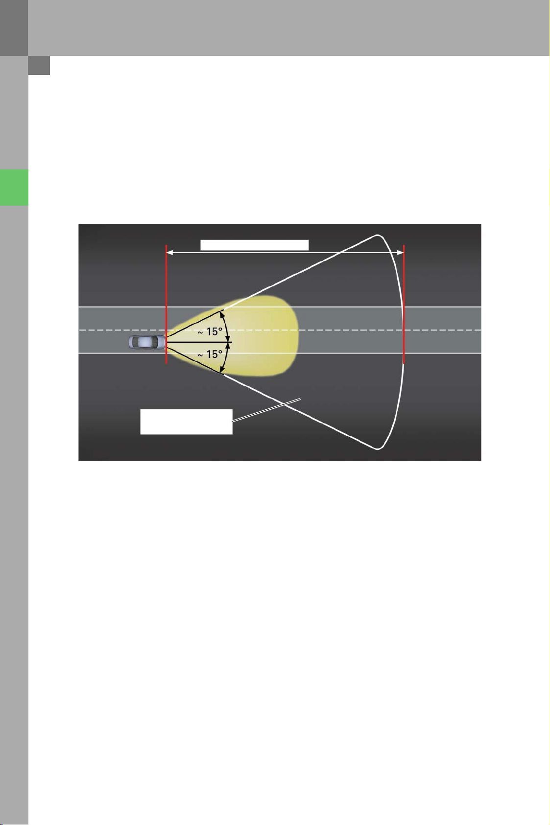
The following illustrations, which show the mode of
operation of the Headlight Assist System in miscellaneous traffic situations, are not true to scale. They
are schematic diagrams which are intended to provide an insight into the basic mode of operation of
the Headlight Assist System.
Max. 1000 m
Exact dim-up times or dim-down times cannot be
extrapolated from these diagrams. These timings
depend on several factors, such as the visibility conditions, the nature of the road and the luminous
power of the headlights of oncoming vehicles or
traffic ahead.
Range of the Headlight
Assist System
The following illustrations show the range of the
Headlight Assist System, which can extend to 1000 m.
It should be noted that this is the maximum range
and is only achievable in optimum conditions. In reallife traffic situations, however, the actual range will
be below this value.
434_004
A more exact value cannot be given because it heavily
depends on the momentary ambient conditions, such
as visibility, the nature of the road and the type of surroundings.
6
Page 7
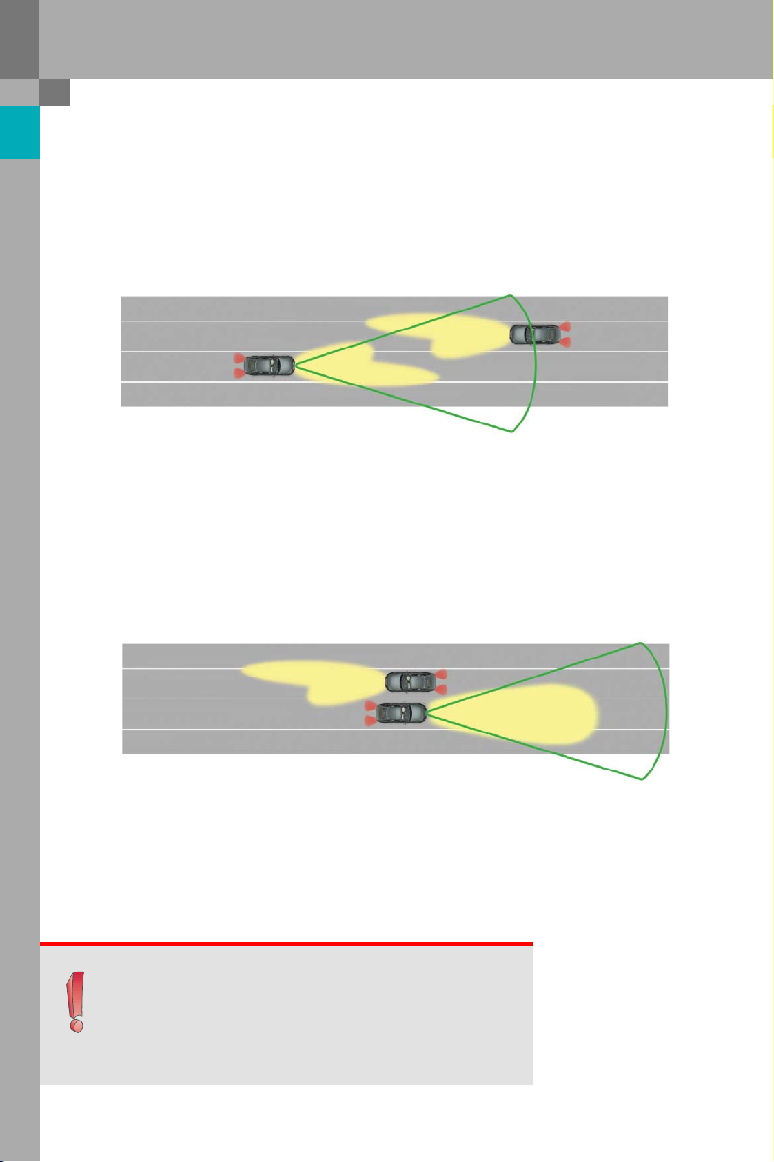
An oncoming vehicle
434_005
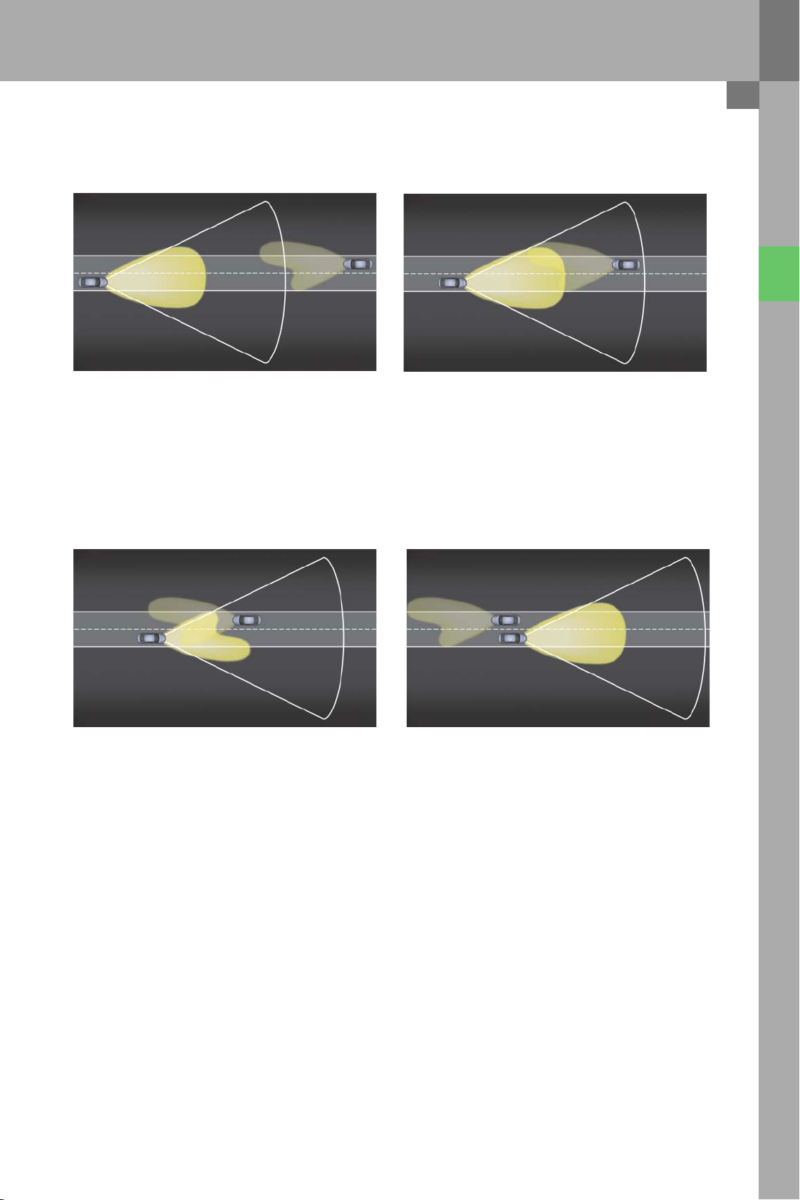
The oncoming vehicle is still outside the range of the
Headlight Assist System.
434_007 434_008
The oncoming vehicle is now so close that the Headlight Assist System dims down in order to avoid dazzling the approaching driver.
434_006
The oncoming vehicle is within the range of the Headlight Assist System. However, the vehicle is still far
enough away, so the Headlight Assist System does
not dim down yet.
The Headlight Assist System has not detected the
oncoming vehicle for over 1 second. For this reason,
the main-beam headlights are switched on again.
7
Page 8
Mode of operation of the Headlight Assist System
A vehicle ahead
434_009 434_010
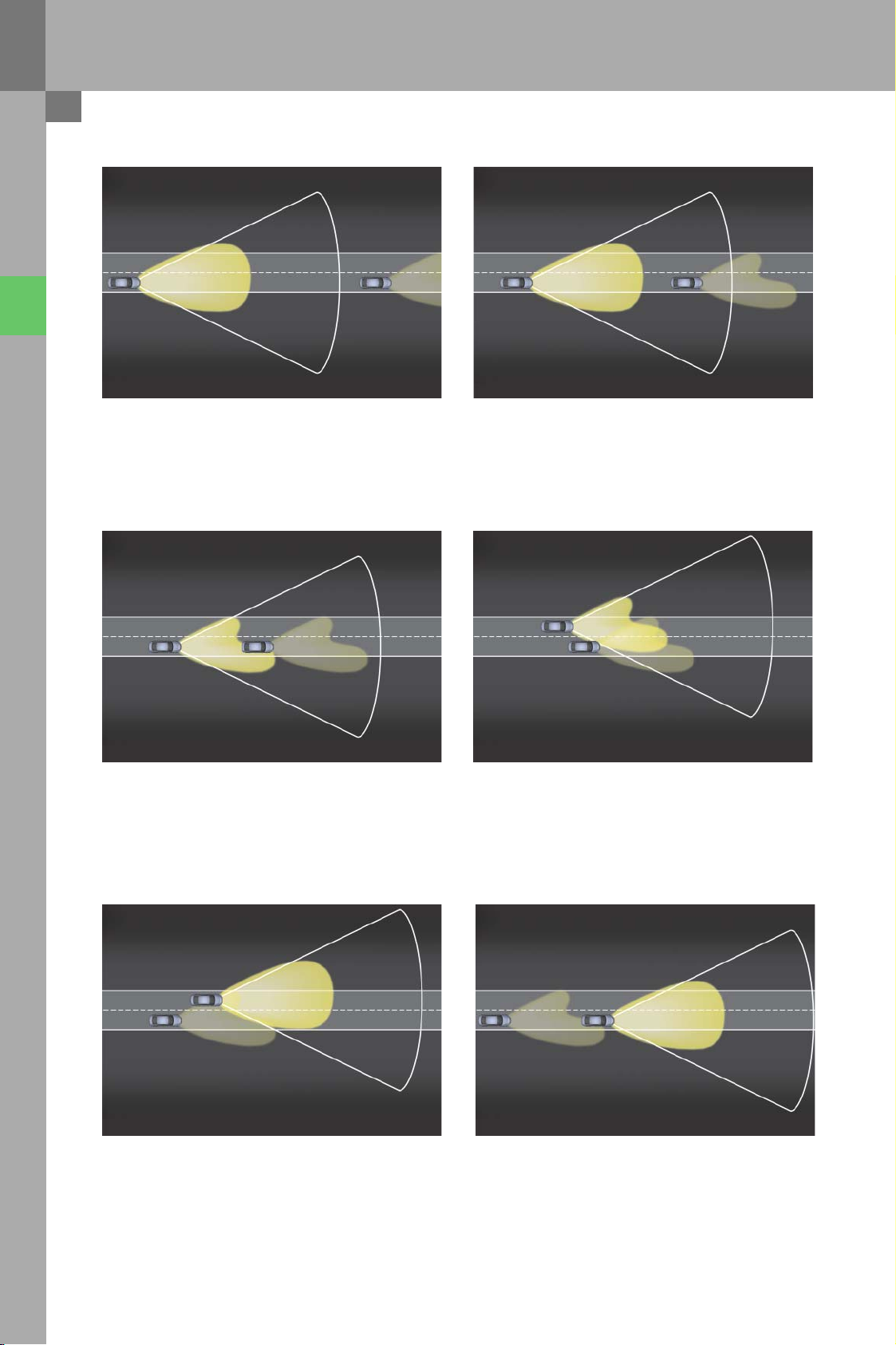
The vehicle ahead is still outside the range of the
Headlight Assist System.
434_011 434_012
The vehicle ahead is now so close that the Headlight
Assist System has dimmed down.
The vehicle ahead is within the range of the Headlight Assist System. However, the vehicle is still far
enough away, so the Headlight Assist System leaves
the main-beam headlights switched "on".
The vehicle ahead is being overtaken. Because the
Headlight Assist System still detects the taillights of
the other vehicle during the last 3 seconds of the
overtaking manoeuvre, the dipped headlights
remain switched "on" for the time being.
The taillights of the vehicle that has been overtaken
have not been detected for more than 3 seconds. For
this reason, the main-beam headlights are switched
on again.
8
434_013 434_014
The overtaking manoeuvre has been completed and
the vehicle with Headlight Assist continues driving
with the main-beam headlights on.
Page 9

Driving through a built-up area
434_015 434_016
The built-up area is still outside the range of the
Headlight Assist System. For this reason, the Headlight Assist System has switched on the main-beam
headlights.
434_017 434_018
Because a sufficiently illuminated built-up area has
been detected, the main-beam headlights are
switched off.
The built-up area is now within the range of the
Headlight Assist System. The main-beam headlights
are still switched on.
The vehicle has passed through the built-up area
and the Headlight Assist System detects no further
light sources within its range. For this reason, the
main-beam headlights are switched on again.
Note
Light sources in a built-up area identified as such
by the Headlight Assist System are required to
have a minimum luminous intensity. For example,
roadside street lamps meet this condition.
9
Page 10

Mode of operation of the Headlight Assist System
A built-up area at a distance from the road
434_019 434_020
The built-up area, located at a distance from the
road, is still outside the range of the Headlight Assist
System. The main-beam headlights are switched on.
434_021 434_022
The system determines that the built-up area is not
sufficiently illuminated. Because the vehicle is travelling faster than 90 kph, the main-beam headlights
remain switched on.
Had the vehicle been travelling at less than 90 kph,
the main-beam headlights would have been switched
off.
The 90 kph speed threshold is another threshold relevant to the Headlight Assist System. However, it is
only applied in this specific case.
The built-up area is now within the range of the
Headlight Assist System. The main-beam headlights
remain switched on.
The built-up area is no longer within the range of
the Headlight Assist System. The main-beam headlights remain switched on.
10
Page 11

A single house by the roadside
434_023 434_024
The house and the street lamp are still outside the
range of the Headlight Assist System. The mainbeam headlights are switched on.
434_025 434_026
Because only a single light source is detected, the
main-beam headlights remain switched on.
The house and the street lamp are now within the
range of the Headlight Assist System. The mainbeam headlights remain switched on.
The house and the street lamp are again outside the
range of the Headlight Assist System. The mainbeam headlights remain switched on.
11
Page 12

System operation and displays
System operation
Activating the Headlight Assist System:
To activate the Headlight Assist System, the rotary
light switch must be in the "AUTO" position. The
Headlight Assist System can be activated by flicking
the main-beam stalk forward.
The Headlight Assist System must be reactivated
during each terminal 15 cycle.
flick forward
"stalk not actuated" position
Deactivating the Headlight Assist System:
The Headlight Assist System is permanently deactivated when the rotary light switch is moved out of
the "AUTO" position. Flicking the main-beam stalk
forward deactivates the Headlight Assist System
until the main-beam stalk is flicked forward again.
pull back
Overriding the Headlight Assist System:
The driver can override any decision made by the
activated Headlight Assist System (main-beam
headlights on or off) at any time.
Main-beam headlights switched on by the Headlight
Assist System can be switched off by pulling the
main-beam stalk back. This also deactivates the
Headlight Assist System.
If the Headlight Assist System has switched on only
the dipped headlights, the main-beam headlights
can be switched on by flicking the main-beam stalk
forward. This also deactivates Headlight Assist System.
434_027
New features of the indicator and main-beam stalk:
On introduction of the Headlight Assist System, the
relevant models will be equipped with a modified
indicator and main-beam stalk. The new main-beam
stalk no longer engages in its end position when it
is pushed forward, but returns to its initial position
after it is released. The software of the steering column electronics J527 monitors when the mainbeam stalk is flicked forward and pulled back, and
processes the information accordingly.
12
Page 13

The operating logic of the Headlight Assist System
Activation and deactivation of the Headlight Assist System, overriding of the Headlight Assist System by the
driver, manual switching on and off of the main-beam headlights and actuation of the headlight flasher can
be controlled in two ways by using the main-beam stalk:
• By flicking the main-beam stalk forward
and
• By pulling the main-beam stalk back
To implement all these functions with only 2 means of operation, the software of the onboard power supply
control unit J519 incorporates an operating logic. The operating logic can be represented in the form of a status diagram with 4 principal states:
• Headlight Assist System (HAS) deactivated and main-beam headlights "off"
• Headlight Assist System (HAS) deactivated and main-beam headlights "on"
• Headlight Assist System (HAS) activated and main-beam headlights "off"
• Headlight Assist System (HAS) activated and main-beam headlights "on"
Ter m in a l 1 5 "on "
and rotary light switch
set to AUTO
Main-beam headlights
"off"
HAS deactivated
flick
flick
forward
forward
(dipped
headlights
"off")
Main-beam headlights
"off"
HAS activated
Operating logic of the Headlight Assist System (HAS)
pull back
relea se
"
d
n
r
o
a
"
w
s
r
t
o
h
f
g
k
i
l
c
i
d
l
f
a
e
h
d
e
p
p
i
d
(
situation-dependent
pull back
Headlight flasher
pull back
)
(automatic)
Headlight flasher
Main-beam headlights
"on"
HAS deactivated
flick
forward
p
u
l
l
b
a
c
k
flick
forward
Main-beam headlights
"on"
HAS activated
relea se
434_028
13
Page 14

System operation and displays
Displays in the dash panel insert
Warning lamp in the dash panel insert
When the Headlight Assist System is active, this is
indicated in the dash panel insert in the position at
which total mileage (km) is otherwise displayed
when Headlight Assist is deactivated.
If the main-beam headlights are "on", the familiar
blue main-beam headlight warning lamp in the dash
panel insert will be lit. This lamp comes on regardless of whether the main-beam headlights have
been switched on manually or by the Headlight
Assist System.
Fault texts in the dash panel insert
434_029
• Fault message "System malfunction"
If the Headlight Assist System is no longer available
to the customer due to a fault, this is indicated to
the driver by the fault message shown adjacent,
which appears in the centre display of the dash
panel insert.
• Fault message "Please wash windscreen"
If the software of the Headlight Assist System establishes that the visibility of the camera is impaired,
the fault message shown adjacent instructs customer to wash the windscreen or to remove ice,
road tax discs or stickers.
Headlight
Assist:
System
malfunction
434_030
Headlight
Assist:
Please
wash
windscreen
434_031
Note
The camera lens is located
within the wiping field of the windscreen wiper
14
Page 15

Functional implementation in the vehicle
Component parts of the Headlight Assist System
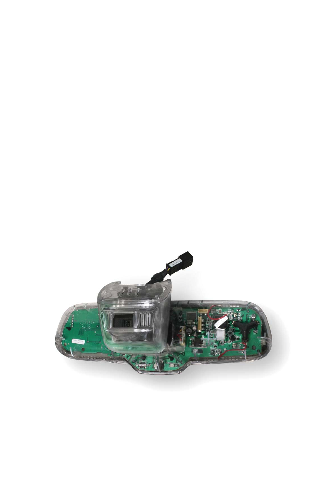
The electronics and optics of the Headlight Assist
System are wholly integrated in the rear-view mirror.
The camera of the Headlight Assist System is built
into the base of the rear-view mirror, which is
securely attached to the windscreen. The camera is
a special black-and-white camera.
The Headlight Assist control unit J844, on the other
hand, is located in the actual rear-view mirror, which
is mounted movably. The Headlight Assist control
unit is an Extended-CAN user and exchanges information with other control units via this bus.
Headlight Assist System camera
Rear-view mirror / vehicle electronics
8-pin connector
Headlight Assist
camera
434_032
PCB accommodating the hardware
of the Headlight Assist
control unit J844
Sensor of compass in rear-view mirror
434_033
15
Page 16

Functional implementation in the vehicle
The electrical interface of the rear-view mirror
The rear-view mirror has an 8-pin connector, which
connects the Headlight Assist control unit J844, the
electronics of the automatic mirror-dimming function and the humidity sender G355 to other vehicle
electronics.
The Headlight Assist control unit J844 and the electronics of the automatic mirror-dimming function
are mounted on a common PCB. The two EC lines
are required to implement the automatic mirrordimming function. They provide for dimming down
of the two exterior mirrors. A discrete line indicates
to the function whether the interior light has just
been switched on or off.
Mirror base
Headlight Assist
camera
The Headlight Assist System exchanges information
with other in-vehicle control units via 2 ExtendedCAN lines. The automatic mirror-dimming function
receives via the CAN bus information on whether
the reversing light is currently switched on or off.
The electronics in the rear-view mirror receive their
voltage supply via a terminal 15 line and a terminal
31 line.
The humidity sender G355 still requires an additional LIN bus line in order to communicate with the
convenience system central control unit J393, its
LIN master. If the vehicle is equipped with a singlezone air conditioning system, the humidity sender
(and hence the LIN bus line) is not installed.
to the exterior mirror
EC = electrochromatic
Headlight Assist control
unit J844 and automatic
mirror dimming function
EC -
EC +
Termin a l 1 5
Termin a l 3 1
Extended-CAN low
Interior light signal
Extended-CAN high
Humidity
sensor
G355
Rear-view mirror
LIN bus
434_034
16
Page 17

The distributed "Headlight Assist" function
The Headlight Assist function is distributed among
the Headlight Assist control unit J844 and the
onboard power supply control unit J519 . The Headlight Assist control unit J844 determines from the
camera image the current ambient conditions and
the traffic situation ahead of the vehicle. The Headlight Assist control unit receives via the CAN bus
information on the vehicle's current speed and the
instruction of the rain and light detector sensor to
switch the dipped headlights on or off. Depending
on this information, the Headlight Assist control
unit sends to the onboard power supply control unit
J519 a recommendation to switch the main-beam
headlights on or off.
The onboard power supply control unit J519 implements the operating logic in its software. When the
headlight control stalk is moved forward or back,
the onboard power supply control unit J519 calculates the next state depending on the current state
(main-beam headlights on or off; Headlight Assist
activated or deactivated). Depending on the next
state, the onboard power supply control unit activates or deactivates the Headlight Assist System or
switches the main-beam headlights on or off.
The onboard power supply control unit also utilises
CAN messages to control status displays and fault
texts belonging to the Headlight Assist function in
the dash panel insert.
On vehicles fitted with xenon headlights, the mainbeam headlights are switched on by activating the
two dipped headlight shutters V294 and V295. In
this case, the dipped and main beams on each side
of the vehicle are realised by a single gas discharge
lamp only.
On vehicles equipped with halogen headlights, the
dipped and main beams are separate. Accordingly,
the onboard power supply control unit activates
the two main-beam headlights M30 and M32
directly in order to switch on the main beam.
Headlight Assist control unit J844
Diagnostics of
the Headlight
Image
processing
Assist System
Link to other
vehicle
variables
Monitoring of
traffic
situation
Measurement
of ambient
brightness
Recommendation: "Main-beam headlights on or off"
Onboard power supply control unit J519
Activates
status indication
in dash panel
Implementation
of operating
logic
insert
Headlight
Assist camera
Activates
fault texts in
dash panel
insert
Activation of
main-beam
headlight
434_035
17
Page 18

Functional implementation in the vehicle
Communication structure
The following diagram summarises all the control
units incorporated in the Audi Headlight Assist
function. It also shows the various bus systems via
which the control units communicate with each
other.
Headlight Assist
control unit
J844
Extended
-CAN
ABS
control unit
J104
Data bus diagnostic
interface
J533
This communication structure applies to the A4 and
A5 models. A different communication structure
may apply to other models.
Main-beam stalk
Steering column
electronics
control unit J527
Convenience CAN
Onboard power
supply control unit
J519
discrete
LIN bus
Light switch
E1
Dash panel
insert/running gear CAN
Control unit in
dash panel insert
J285
Headlight Assist control unit J844:
The Headlight Assist control unit J844 sends to the
onboard power supply control unit J519 a recommendation to switch the main-beam headlights on
or off depending on the current vehicle, traffic and
ambient conditions. The current traffic and ambient
conditions are determined from the images produced by the Headlight Assist camera.
Term i n a l 5 6 a
Xenon headlights
Dipped headlight
shutter,
left V294
Term i n a l 5 6 a
Xenon headlights
Dipped headlight
shutter, right V295
Onboard power supply control unit J519:
The onboard power supply control unit J519 indicates to the dash panel insert control unit J285
whether the warning lamp of the main-beam headlights and the Headlight Assist System have to be
activated or not. If necessary, onboard power supply
control unit also instructs fault texts to be displayed
in the centre display of the dash panel insert.
Rain and light
detector
sensor G397
434_036
18
Page 19

Data bus diagnostic interface J533:
Steering column electronics control unit J527:
The data bus diagnostic interface J533 serves the
exchange of messages between various CAN data
bus systems. The accessibility of the Headlight
Assist control unit J844 and the operability of individual bus systems can also be checked for diagnostic purposes.
ABS control unit J104:
The ABS control unit J104 keeps the Headlight
Assist control unit J844 continuously informed of
the current vehicle speed. This information is
required because the Headlight Assist System has
to take various speed thresholds into account. The
Headlight Assist System also receives from control
unit J104 the yaw rate, which is required
for auto-calibration of the Headlight Assist function.
Control unit with display in dash panel insert J285
The control unit with display in dash panel insert
J285 receives from the onboard power supply control unit J519 the information as to whether the
Headlight Assist System is currently activated or
not. Accordingly, the Headlight Assist status indicator lamp in the dash panel insert is switched on or
off. When a fault occurs, the customer is also
informed by means of fault texts. The control unit
with display in dash panel insert J285 also receives
this information from the onboard power supply
control unit J519.
The steering column electronics control unit J527
indicates to the onboard power supply control unit
J519 whether the main-beam stalk has been moved
forward or back. The operating logic in the onboard
power supply control unit requires this information.
Rotary light switch E1:
The rotary light switch E1 indicates to the onboard
power supply control unit the current position of
the rotary light switch. The Headlight Assist can
only be activated in the AUTO position.
Rain and light detector sensor G397:
The rain and light detector sensor G397 instructs
the onboard power supply control unit J519 to
switch the dipped headlights or on off, due to the
momentary ambient conditions. The Headlight
Assist System can only the activate or deactivate
main-beam headlights if the dipped headlights are
currently "on" at the instruction of the rain and light
detector sensor.
19
Page 20

Diagnostics
Diagnostic tasks in the Headlight Assist control unit J844
The Headlight Assist control unit J844 is a self-diagnosable control unit which is addressed by the diagnostic
tester using address word 20.
434_037
• Data blocks
The following information can be extracted from the data blocks of the Headlight Assist System:
– Headlight Assist ready yes / no
– Dimming up recommended by Headlight Assist yes / no
– Headlight Assist camera: unimpaired visibility yes / no
– CAN messages received from convenience system control unit J393 yes / no
– CAN messages received from data bus diagnostic interface yes / no
– CAN messages received from ABS control unit yes / no
– CAN messages received from steering column electronics control unit J527 yes / no
Other data blocks display information about the "Auto dimming rear view mirror" function and about the compass function in the rear-view mirror.
•Encoding
The control unit receives the following encoding information for the Headlight Assist System:
– Headlight type
– Left-hand drive or right-hand drive
– Vertical offset (model-dependent windscreen inclination angle)
– Windscreen transmissivity (translucency of the windscreen; windscreen type)
20
Page 21

• Adaption channels
The Headlight Assist control unit contains the following adaptions:
– Vehicle is a left-hand drive / right-hand drive model
• Final control diagnostics
– The Headlight Assist control unit sends to the onboard power supply control unit J519 the recommenda-
tion to switch on the main-beam headlight. It sends the recommendation regardless of the current traffic
and ambient conditions, as well as other relevant vehicle variables.
To switch on the main-beam headlight, the rotary light switch must be in the "AUTO" position so that the
dipped headlights can be switched on and the Headlight Assist function activated.
In addition, the Headlight Assist System provides the following independent final control diagnoses:
– Dim down rear-view mirror (and exterior mirrors, if fitted)
– Activate all segments of compass in rear-view mirror (if fitted)
• Fault memory entries
The following fault memory entries are possible in the Headlight Assist control unit J844:
– Control unit - electrical fault
– Control unit - faulty
– Control unit - not encoded
– Function deactivation due overtemperature in control unit
– Headlight Assist control unit - impaired visibility
– Headlight Assist control unit - decalibrated
– Supply voltage outside allowable range
– Function impairment due to undervoltage
– Function impairment due to overvoltage
– No communication with the data bus diagnostic interface J533
– No communication with the ABS control unit J104
– No communication with the convenience system central control unit J393
– No communication with the onboard power supply control unit J519
– No communication with the steering column electronics control unit J527
– Extended-CAN – no communication
– Function impairment due to implausible message
– Function impairment due to received error value
Calibration
The Headlight Assist System does not require calibration using special tools. The system carries out auto-calibration continuously, whereby correction parameters are determined. These parameters are taken into
account during image processing.
21
Page 22

Diagnostics
Diagnostics in the onboard power supply control unit J519
• Data blocks
The following information can be extracted from the data blocks of the onboard power supply control unit
J519:
– Headlight Assist ready yes / no
– Dimming up recommended by Headlight Assist yes / no
– Headlight Assist control unit faulty
– Headlight Assist camera: unimpaired visibility yes / no
– Dash panel insert should switch on Headlight Assist warning lamp yes / no
– Message text
"Headlight Assist: System malfunction"
"Headlight Assist: Please wash windscreen"
is currently indicated in the dash panel insert yes / no
•Encoding
The control unit receives the following encoding information for the Headlight Assist System:
– Headlight Assist installed / not installed
• Fault memory entries
The following fault memory entries are possible in the onboard power supply control unit J519:
– No communication with the Headlight Assist control unit J844
– Headlight Assist control unit J844 faulty – Please read out fault memory J844
22
Page 23

Test yourself
Which of the following answers is correct?
Sometimes only one answer is correct.
At other times, more than one answer may be correct – or all of them!
1. Which circumstances cause the main-beam headlights to be switched off by the Headlight
Assist System?
A) When the system detects a pedestrian
B) When the system detects a vehicle ahead
C) When the vehicle speed drops below 15 kph
D) When a sufficiently illuminated built-up area is detected
2. How is the Headlight Assist System activated?
A) Either via the MMI panel or via the menu in the dash panel insert (depending on vehicle)
B) Using the Headlight Assist button E699 in the dash panel insert
C) By flicking the main-beam stalk forward
D) By turning the rotary light switch to the "Headlight Assist" position
Annex
3. How does the Headlight Assist System monitor the vehicle's surroundings?
A) Using a separate camera integrated in the base of the rear-view mirror
B) It uses the radar sensor of the ACC system
C) It uses the camera of the Audi lane assist system
D) By means of an infrared sensor located behind the vehicle's radiator grille
Solutions: 1) B,D 2) C 3) A
23
Page 24

Vorsprung durch Technik www.audi.de
434
All rights reserved.
Technical specifications
subject to change without
notice.
Copyright
AUDI AG
I/VK-35
Service.training@audi.de
Fax +49-841/89-36367
AUDI AG
D-85045 Ingolstadt
Technical status: 04/08
Printed in Germany
A07.5S00.50.20
 Loading...