


Audi A4 englisch 9.07
Audi A4
Owner's Manual
li 2007 9:16 09

© 2007 AUDI AG
AUDI AG works continuously to develop and further improve all
models. You will appreciate that we must therefore reserve the right
to alter any part of the vehicle and its equipment or technical specifications at any time. No legal commitment can therefore be
implied by the information, illustrations or descriptions in this
Manual.
No part of this Owner's
M
translated without the w
r
under the laws of copyri
g
Subject to alteration and
Date of publication: 27.0
6
For the sake of t
h
This paper was bleached
li 2007 9:16 09
Foreword
Thank you for choosing the Audi A4.
The new Audi A4 combines the latest technology with numerous features for your comfort and
convenience. To help you get the best out of these features in everyday use, we recommend that
you read this Manual carefully so you can quickly become familiar with your vehicle in detail.
As well as information on how to use the controls and equipment, the Owner's Manual contains
important notes on care and maintenance. These are relevant to your safety and will help preserve
your car's value. The Manual also offers useful driving tips and advice, together with some suggestions on how to drive your car with minimum impact on the environment.
In addition to this Owner's Manual, the Service Wallet also includes the Service Schedule for your
vehicle. This booklet contains important information on Audi service requirements and lists the
vehicle's fuel consumption figures. The Service Wallet also includes operating manuals for
optional on-board systems such as the radio, navigation and telephone. We recommend that you
keep the Service Wallet in the car at all times.
Should you have any further questions regarding your car or if you suspect that your owner's literature is not complete, please contact your Audi dealer or importer. They are always glad to answer
your queries and note any suggestions you may have.
We wish you safe and enjoyable motoring with your Audi A4.
AUDI AG
document_0900452a81b1b9de.book Seite 1 Donnerstag, 26. Juli 2007 9:16 09
Contents2
Contents
Notes on this Owner's
Manual
. . . . . . . . . . . . . . . . . . . . . .
Controls . . . . . . . . . . . . . . . . . . . . .
Controls and displays . . . . . . . . . .
Overview . . . . . . . . . . . . . . . . . . . . . .
Instruments and
warning/indicator lamps . . . . . . .
Instruments . . . . . . . . . . . . . . . . . . . .
Fuel gauge . . . . . . . . . . . . . . . . . . . . .
Warning and indicator lamps . . . . .
Driver information system . . . . . .
Introduction . . . . . . . . . . . . . . . . . . . .
On-board computer . . . . . . . . . . . . .
Speed warning function . . . . . . . . .
Auto-check control . . . . . . . . . . . . . .
Tyre pressure monitoring system .
Doors and windows . . . . . . . . . . . .
Central locking system . . . . . . . . . .
Boot lid . . . . . . . . . . . . . . . . . . . . . . . .
Child-proof catches . . . . . . . . . . . . .
Electric windows . . . . . . . . . . . . . . .
Sun roof . . . . . . . . . . . . . . . . . . . . . . .
Lights and vision . . . . . . . . . . . . . . .
Lights . . . . . . . . . . . . . . . . . . . . . . . . .
Interior lights . . . . . . . . . . . . . . . . . . .
Clear vision . . . . . . . . . . . . . . . . . . . .
Windscreen wipers . . . . . . . . . . . . .
Rear-view mirrors . . . . . . . . . . . . . .
Digital compass . . . . . . . . . . . . . . . .
Seats and storage . . . . . . . . . . . . .
Manual adjustment of front seats
Electric adjustment of front seats
Seat memory . . . . . . . . . . . . . . . . . .
Head restraints . . . . . . . . . . . . . . . .
Front armrest . . . . . . . . . . . . . . . . . .
Luggage compartment . . . . . . . . .
Roof carrier . . . . . . . . . . . . . . . . . . . .
Roof load . . . . . . . . . . . . . . . . . . . . .
Cup holders . . . . . . . . . . . . . . . . . . .
Ashtrays . . . . . . . . . . . . . . . . . . . . . .
Cigarette lighter and electrical
sockets . . . . . . . . . . . . . . . . . . . . . . .
On-board 230 Volt Euro socket . . .
Storage compartments . . . . . . . . .
Heating and cooling . . . . . . . . . . .
Deluxe automatic air conditioner .
Deluxe automatic air conditioner -
basic settings . . . . . . . . . . . . . . . . . .
Deluxe automatic air conditioner
plus . . . . . . . . . . . . . . . . . . . . . . . . . .
Deluxe automatic air conditioner
plus - basic settings . . . . . . . . . . . .
Auxiliary heating and auxiliary
ventilation . . . . . . . . . . . . . . . . . . . . .
Seat heating . . . . . . . . . . . . . . . . . . .
Driving . . . . . . . . . . . . . . . . . . . . . . . . .
Steering . . . . . . . . . . . . . . . . . . . . . . .
Ignition lock . . . . . . . . . . . . . . . . . . .
Starting and stopping the engine
with the advanced key . . . . . . . . . .
Electro-mechanical parking brake
Cruise control system . . . . . . . . . . .
adaptive cruise control (ACC) . .
Speed and distance control system
Driver messages . . . . . . . . . . . . . . .
System limitations . . . . . . . . . . . . . .
Audi braking guard . . . . . . . . . . . . .
Audi lane assist . . . . . . . . . . . . . . . .
Audi lane assist . . . . . . . . . . . . . . . .
Audi side assist . . . . . . . . . . . . . . . .
Lane change assist feature . . . . . .
Notes . . . . . . . . . . . . . . . . . . . . . . . . .
Audi drive select . . . . . . . . . . . . . . .
Adjusting the vehicle set-up . . . . .
Automatic gearbox . . . . . . . . . . . . .
multitronic ®, tiptronic (6-speed
gearbox) . . . . . . . . . . . . . . . . . . . . . . .
Parking aid . . . . . . . . . . . . . . . . . . . . .
General notes . . . . . . . . . . . . . . . . . .
Audi parking system . . . . . . . . . . . .
Audi parking system plus . . . . . . . .
Audi parking system advanced . . .
Switching display and acoustic
signals on and off . . . . . . . . . . . . . .
Towing bracket . . . . . . . . . . . . . . . . .
Error messages . . . . . . . . . . . . . . . . .
HomeLink . . . . . . . . . . . . . . . . . . . . . .
Universal transmitter . . . . . . . . . . . .
5
7
9
9
11
11
14
15
21
21
25
28
30
39
42
42
51
53
53
55
57
57
63
64
65
68
71
73
73
74
75
77
78
79
83
84
85
86
87
89
90
93
93
100
101
109
110
114
116
116
116
118
121
125
128
128
134
140
142
145
145
149
149
156
159
159
162
162
169
169
169
170
171
177
177
178
179
179
document_0900452a81b1b9de.book Seite 2 Donnerstag, 26. Juli 2007 9:16 09
Contents 3
Controls Safety Driving tips General maintenance Self-help Technical data
Safety . . . . . . . . . . . . . . . . . . . . . . .
Safe driving . . . . . . . . . . . . . . . . . . . .
General notes . . . . . . . . . . . . . . . . . .
Correct sitting positions . . . . . . . .
Pedal area . . . . . . . . . . . . . . . . . . . . .
Stowing luggage safely . . . . . . . . .
Seat belts . . . . . . . . . . . . . . . . . . . . . .
Why is it so important to use seat
belts? . . . . . . . . . . . . . . . . . . . . . . . . .
Forces acting in a collision . . . . . .
How to wear seat belts properly .
Belt tensioners . . . . . . . . . . . . . . . . .
Airbag system . . . . . . . . . . . . . . . . .
Description of airbag system . . . .
Front airbags . . . . . . . . . . . . . . . . . .
Side airbags . . . . . . . . . . . . . . . . . . .
Head-protection airbags
(sideguard) . . . . . . . . . . . . . . . . . . . .
Deactivating the front passenger's
airbag via the key-operated switch
Child safety . . . . . . . . . . . . . . . . . . . .
Points to remember if children are
travelling in the car . . . . . . . . . . . . .
Child safety seats . . . . . . . . . . . . . .
Fitting child safety seats . . . . . . . .
Driving tips . . . . . . . . . . . . . . . .
Intelligent technology . . . . . . . . . .
Electronic stabilisation program
(ESP) . . . . . . . . . . . . . . . . . . . . . . . . . .
Brakes . . . . . . . . . . . . . . . . . . . . . . . . .
Power steering (servotronic) . . . . .
Four-wheel drive (quattro®) . . . . . .
Power management . . . . . . . . . . . .
Your vehicle and the
environment . . . . . . . . . . . . . . . . . . .
Running in . . . . . . . . . . . . . . . . . . . . .
Emission control systems . . . . . . .
How to improve economy and
minimise pollution . . . . . . . . . . . . . .
Environmental compatibility . . . . .
Towing a trailer . . . . . . . . . . . . . . . .
Driving the vehicle with a trailer or
caravan . . . . . . . . . . . . . . . . . . . . . . .
Removable towing bracket . . . . . .
General maintenance . . .
Care of vehicle and cleaning . . .
General notes . . . . . . . . . . . . . . . . . .
Care of exterior . . . . . . . . . . . . . . . . .
Care of interior . . . . . . . . . . . . . . . . .
Fuel and filling the tank . . . . . . . .
Petrol . . . . . . . . . . . . . . . . . . . . . . . . . .
Diesel . . . . . . . . . . . . . . . . . . . . . . . . .
Filling the tank . . . . . . . . . . . . . . . . . .
Checking and topping up fluids
Bonnet . . . . . . . . . . . . . . . . . . . . . . . .
Engine compartment layout . . . . . .
Engine oil . . . . . . . . . . . . . . . . . . . . . .
Cooling system . . . . . . . . . . . . . . . . .
Brake fluid . . . . . . . . . . . . . . . . . . . . .
Battery . . . . . . . . . . . . . . . . . . . . . . . .
Windscreen washer . . . . . . . . . . . . .
Wheels and tyres . . . . . . . . . . . . . . .
Wheels . . . . . . . . . . . . . . . . . . . . . . . .
Run flat tyres . . . . . . . . . . . . . . . . . . .
Accessories and modifications
to the vehicle . . . . . . . . . . . . . . . . . . .
Accessories and replacement
parts . . . . . . . . . . . . . . . . . . . . . . . . . .
Modifications . . . . . . . . . . . . . . . . . .
Radio transmitters and business
equipment . . . . . . . . . . . . . . . . . . . . .
185
186
186
188
191
192
194
194
195
197
199
201
201
203
205
207
208
210
210
213
216
221
222
222
224
225
226
226
229
229
229
229
231
232
232
235
243
244
244
244
247
251
251
251
252
254
254
256
257
260
262
263
267
268
268
274
277
277
277
278
document_0900452a81b1b9de.book Seite 3 Donnerstag, 26. Juli 2007 9:16 09
Contents4
Self-help . . . . . . . . . . . . . . . . . . . . .
Self-help . . . . . . . . . . . . . . . . . . . . . . . .
Warning triangle . . . . . . . . . . . . . . . .
First-aid kit . . . . . . . . . . . . . . . . . . . . .
Fire extinguisher . . . . . . . . . . . . . . . .
Tools and Tyre Mobility System . . .
Compact temporary spare wheel*
Tyre repairs . . . . . . . . . . . . . . . . . . . .
Changing a wheel . . . . . . . . . . . . . .
Jump-starting . . . . . . . . . . . . . . . . . .
Tow-starting and towing away . . .
Fuses and bulbs . . . . . . . . . . . . . . . .
Fuses . . . . . . . . . . . . . . . . . . . . . . . . . .
Bulbs . . . . . . . . . . . . . . . . . . . . . . . . . .
Changing bulbs for headlights . . .
Changing bulb for front fog lights
Changing bulbs for rear lights in
side panel . . . . . . . . . . . . . . . . . . . . . .
Changing bulbs in boot lid . . . . . . .
Number plate light . . . . . . . . . . . . . .
Technical data . . . . . . . . . . . .
General notes . . . . . . . . . . . . . . . . . .
Explanation of technical data . . . .
Dimensions . . . . . . . . . . . . . . . . . . . .
Capacities . . . . . . . . . . . . . . . . . . . . .
Vehicle identification data . . . . . . .
Performance, weights and
dimensions . . . . . . . . . . . . . . . . . . . .
Petrol engines . . . . . . . . . . . . . . . . .
Diesel engines . . . . . . . . . . . . . . . . .
Index . . . . . . . . . . . . . . . . . . . . . . . .
281
282
282
282
283
283
284
285
288
293
295
300
300
304
306
310
311
314
315
319
320
320
320
321
321
323
323
325
329
document_0900452a81b1b9de.book Seite 4 Donnerstag, 26. Juli 2007 9:16 09
Notes on this Owner's Manual 5
Controls Safety Driving tips General maintenance Self-help Technical data
Notes on this Owner's Manual
This Owner's Manual contains important information, tips, suggestions and warnings.
Please ensure that this Owner's Manual is always kept in the vehicle.
It should always be available to anyone else driving the vehicle, i.e.
anyone renting, borrowing or buying the vehicle from you.
This manual describes the equipment available for the vehicle at the
time of going to print. Some of the equipment described here will
not be available until a later date, or may only be available in certain
markets.
Some sections of this Owner's Manual do not apply to all vehicles.
If this is the case, a text at the start of the section indicates which
vehicles it applies to, e.g. “Applies to ve hicles: with auxi liary heater”.
This optional equipment is also marked with an asterisk “*”.
Illustrations are intended as a general guide, and may vary from the
equipment fitted in your vehicle in some details.
At the beginning of this Owner's Manual, you will find a table of
contents showing all the items described in this manual in the order
in which they appear. An alphabetical index is included at the end
of the Owner's Manual.
All references to positions such as “left”, “right”, “front” or “rear”
are given as seen facing in the direction of travel.
* optional equipment
The section is continued on the following page.
Denotes the end of a section.
® Registered trademarks are marked ®. However, the absence of
this symbol does not constitute a waiver of the rights
concerning any proprietary name.
⇒ Refers to a “WARNING” within the same section. If the
WARNING symbol is followed by a page number the warning text
referred to is included in a different section.
WARNING
Texts with this symbol contain safety information. They warn you
of serious dangers, possibly involving accident or injury.
Caution
Texts with this symbol draw your attention to a possible risk of
damage to your vehicle.
For the sake of the environment
Texts with this symbol refer to points relevant to the protection of
the environment.
Note
Texts with this symbol contain additional information of a more
general nature.
document_0900452a81b1b9de.book Seite 5 Donnerstag, 26. Juli 2007 9:16 09
6
document_0900452a81b1b9de.book Seite 6 Donnerstag, 26. Juli 2007 9:16 09
7Controls
document_0900452a81b1b9de.book Seite 7 Donnerstag, 26. Juli 2007 9:16 09
Controls and displays8
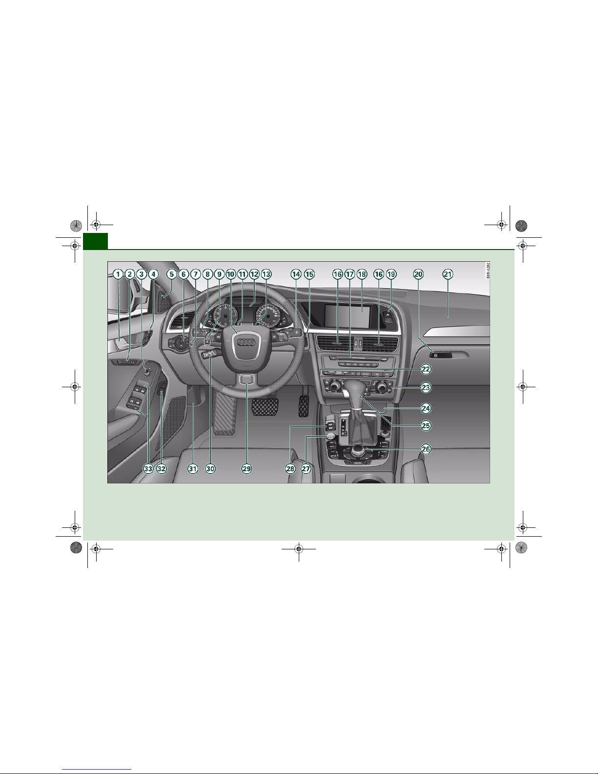
Fig. 1 Some of the items of equipment listed in this section are only fitted on certain models or are optional extras.
document_0900452a81b1b9de.book Seite 8 Donnerstag, 26. Juli 2007 9:16 09
Controls and displays 9
Controls Safety Driving tips General maintenance Self-help Technical data
Controls and displays
Overview
Door handle
Seat memory . . . . . . . . . . . . . . . . . . . . . . . . . . . . . . . . . .
Electric adjuster for exterior mirrors . . . . . . . . . . . . . . .
Central locking switch . . . . . . . . . . . . . . . . . . . . . . . . . . .
Button for side assist . . . . . . . . . . . . . . . . . . . . . . . . . . .
Light switch . . . . . . . . . . . . . . . . . . . . . . . . . . . . . . . . . . .
Instrument lighting . . . . . . . . . . . . . . . . . . . . . . . . . . . . .
Control lever for:
− Turn signals and main beam headlights . . . . . . . . .
− lane assist . . . . . . . . . . . . . . . . . . . . . . . . . . . . . . . . . .
Headlight range control . . . . . . . . . . . . . . . . . . . . . . . . .
Steering wheel with:
− Horn
− Driver's airbag . . . . . . . . . . . . . . . . . . . . . . . . . . . . . . .
− Controls for audio, TV*, telephone and speech
dialogue system*
− Paddle levers for tiptronic gearshift . . . . . . . . . . . . .
SET button . . . . . . . . . . . . . . . . . . . . . . . . . . . . . . . . . . . .
Instrument cluster . . . . . . . . . . . . . . . . . . . . . . . . . . . . . .
Reset button for trip recorder . . . . . . . . . . . . . . . . . . . .
Control lever for:
− Windscreen wipers and washer . . . . . . . . . . . . . . . . .
− On-board computer . . . . . . . . . . . . . . . . . . . . . . . . . . .
Ignition lock . . . . . . . . . . . . . . . . . . . . . . . . . . . . . . . . . . .
Air outlets with thumbwheel . . . . . . . . . . . . . . . . . . . . .
− For deluxe automatic air conditioner . . . . . . . . . . . .
− For deluxe automatic air conditioner plus . . . . . . . .
Depending on equipment fitted:
− Radio
− CD changer
Depending on equipment fitted:
− Radio display
− MMI display
1)
Hazard warning lights
Glove box . . . . . . . . . . . . . . . . . . . . . . . . . . . . . . . . . . . . .
Front passenger's airbag . . . . . . . . . . . . . . . . . . . . . . . . .
Switches for the following (as applicable):
− Audi parking system . . . . . . . . . . . . . . . . . . . . . . . . . .
− Electronic Stabilisation Program (ESP) . . . . . . . . . . .
− Electric sun blind . . . . . . . . . . . . . . . . . . . . . . . . . . . . .
− Control for Audi drive select . . . . . . . . . . . . . . . . . . . .
Air conditioner, depending on equipment fitted:
− Deluxe automatic air conditioner . . . . . . . . . . . . . . . .
− Deluxe automatic air conditioner plus . . . . . . . . . . .
Ashtray with cigarette lighter . . . . . . . . . . . . . . . . . . . . .
Depending on gearbox fitted, gear lever or selector
lever for:
− multitronic® . . . . . . . . . . . . . . . . . . . . . . . . . . . . . . . . .
− Manual gearbox
Depending on equipment fitted:
− MMI control console or
− Switch for Audi parking system . . . . . . . . . . . . . . . . .
− Switch for Electronic Stabilisation Program (ESP
OFF) . . . . . . . . . . . . . . . . . . . . . . . . . . . . . . . . . . . . . . . .
A1A
2
75
A
3
70
A
4
49
A
5
149
A
6
57
A
7
59
A
8
62
145
A
9
61
A
10
203
167
A
11
12
A
12
11
A
13
14
A
14
65
25
A
15
116
A
16
107
99
107
A
17
1)
Depending on the equipment fitted in your vehicle the display screen is either two-coloured or multi-coloured. As the two displays are more or less
identical this Owner's Manual uses the multi-coloured displays for illustration purposes.
A18A
19
A
20
90
A
21
203
A
22
170
222
64
159
A
23
93
101
A
24
86, 87
A
25
162
A
26
170
222
document_0900452a81b1b9de.book Seite 9 Donnerstag, 26. Juli 2007 9:16 09
Controls and displays10
− Switch for electric sun blind . . . . . . . . . . . . . . . . . . .
− Control for Audi drive select . . . . . . . . . . . . . . . . . . .
Start/stop button . . . . . . . . . . . . . . . . . . . . . . . . . . . . . .
Electro-mechanical parking brake . . . . . . . . . . . . . . . .
Adjustable steering column (hidden behind steering
wheel) . . . . . . . . . . . . . . . . . . . . . . . . . . . . . . . . . . . . . . . .
Depending on equipment fitted:
− Cruise control system . . . . . . . . . . . . . . . . . . . . . . . .
− adaptive cruise control
Bonnet lock release . . . . . . . . . . . . . . . . . . . . . . . . . . . .
Switch for releasing the boot lid . . . . . . . . . . . . . . . . . .
Electric windows . . . . . . . . . . . . . . . . . . . . . . . . . . . . . . .
Note
• Please refer to the separate operating manual for instructions on
using the Multi Media Interface (MMI).
• The arrangement of switches and controls on right-hand drive
models* may be slightly different from the layout shown in the illustration ⇒ page 8, fig. 1. However, the symbols used to identify the
controls are the same.
64
159
A
27
118
A
28
121
A
29
116
A
30
125
A
31
254
A
32
51
A
33
53
document_0900452a81b1b9de.book Seite 10 Donnerstag, 26. Juli 2007 9:16 09
Instruments and warning/indicator lamps 11
Controls Safety Driving tips General maintenance Self-help Technical data
Instruments and warning/indicator lamps
Instruments
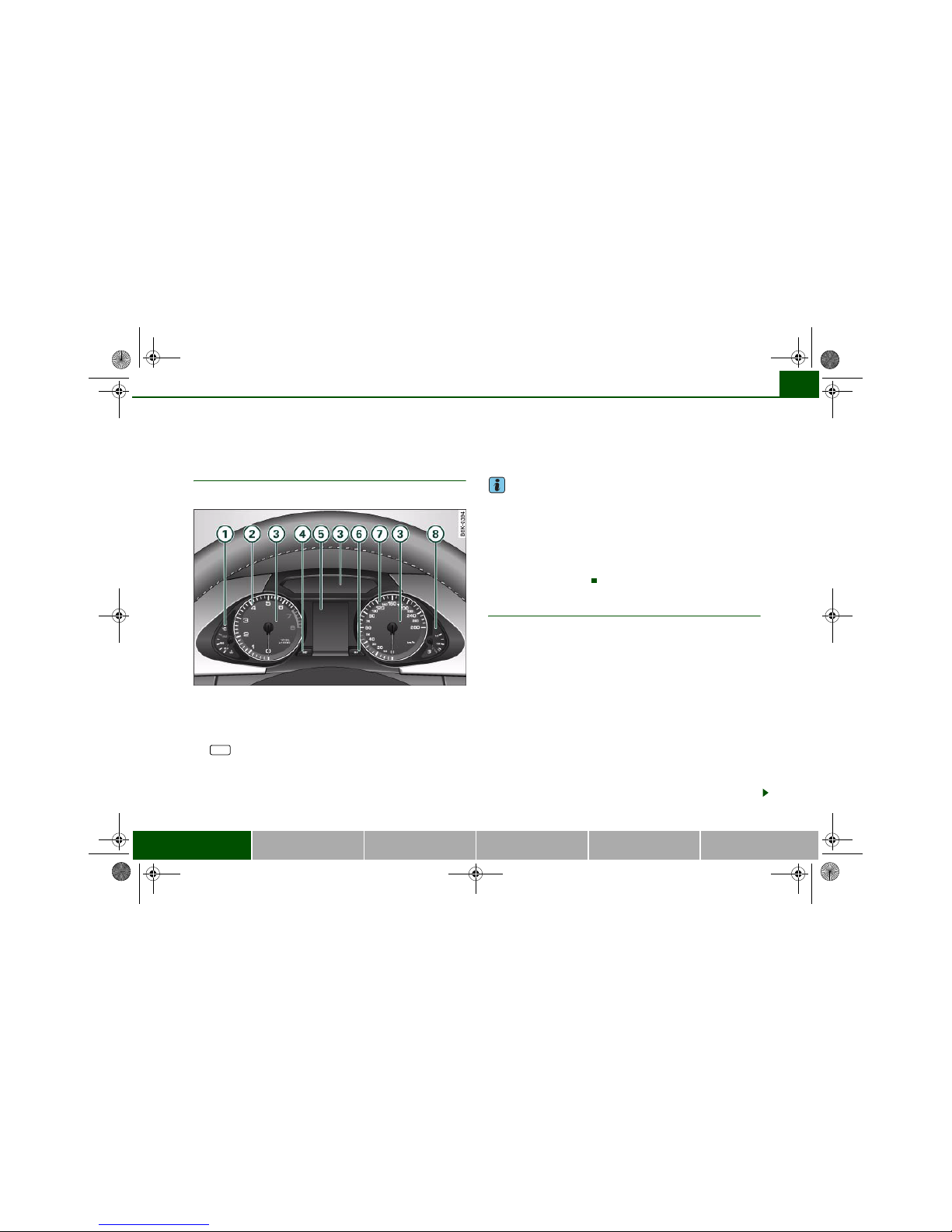
Instrument cluster overview
The instrument cluster is the driver's information centre.
Fig. 2 Overview of instrument cluster
Coolant temperature gauge . . . . . . . . . . . . . . . . . . . . . .
Rev counter . . . . . . . . . . . . . . . . . . . . . . . . . . . . . . . . . . .
Warning and indicator lamps . . . . . . . . . . . . . . . . . . . . .
button . . . . . . . . . . . . . . . . . . . . . . . . . . . . . . . . . . .
Display
− Driver information system . . . . . . . . . . . . . . . . . . . . .
− Date and time display . . . . . . . . . . . . . . . . . . . . . . . . .
− Mileage recorder . . . . . . . . . . . . . . . . . . . . . . . . . . . . .
Reset button for trip recorder . . . . . . . . . . . . . . . . . . . .
Speedometer
Fuel gauge . . . . . . . . . . . . . . . . . . . . . . . . . . . . . . . . . . . .
Note
• The needles in the instrument cluster will sweep across the dials
when you switch on the ignition.
• The instrument lighting (illumination of dials and needles) is
switched on when the ignition is on and the vehicle's lights are off.
The instrument lighting is dimmed automatically as the daylight
starts to fade. This function is intended to remind the driver to
switch on the dipped-beam headlights in good time when light
conditions become poor.
Coolant temperature gauge
The coolant temperature gauge ⇒ fig. 2 only works when the
ignition is switched on. In order to avoid possible damage to the
engine, please read the following notes for the different temperature ranges.
Engine cold
If the needle is still in the lower range of the dial, this indicates that
the engine has not yet reached operating temperature. Avoid high
engine speeds, full acceleration and heavy engine loads.
Normal temperature
In normal operation the needle will settle somewhere in the centre
of the dial once the engine has reached operating temperature. The
needle may also go further up when the engine is working hard at
high outside temperatures. This is no cause for concern provided
the warning symbol in the display does not start flashing.
A
1
11
A
2
12
A
3
15
A
4 SET
12
A
5
21
13
14
A
6
14
A7A
8
14
A
1
document_0900452a81b1b9de.book Seite 11 Donnerstag, 26. Juli 2007 9:16 09
Instruments and warning/indicator lamps12
Warning symbol in instrument cluster
If the symbol lights up in the display, this means that either the
coolant temperature is too high or the coolant level is too low
⇒ page 33.
If the needle is at the top end of the dial, this means the coolant
temperature is too high. Stop the vehicle, switch off the engine and
wait for it to cool down. If the warning lamp starts flashing again
after just a short distance, contact a qualified workshop.
WARNING
• Before opening the bonnet and checking the coolant level,
please observe the warning information on ⇒ page 255, “Working
on components in the engine compartment”.
• Never open the bonnet if you can see or hear steam or coolant
escaping from the engine compartment; there is a risk of being
scalded. Wait until you can no longer see or hear escaping steam
or coolant.
Caution
• Additional lights and other accessories in front of the air inlet
reduce the cooling effect of the radiator. At high outside temperatures and high engine loads, there is a risk of the engine overheating.
• The front spoiler also ensures proper distribution of the cooling
air when the vehicle is moving. If the spoiler is damaged this can
reduce the cooling effect, which could cause the engine to overheat.
You should obtain professional assistance.
Rev counter
The rev counter indicates the number of engine revolutions per minute.
You should select a lower gear if the engine speed drops below
1500 rpm. The start of the red zone on the dial indicates the
maximum engine speed which may be used briefly when the engine
is warm and after it has been run in properly. However, it is advisable
to change up a gear or move the selector lever to “D” (or lift your
foot off the accelerator) before the needle reaches the red zone.
Caution
Never allow the rev counter needle ⇒ page 11, fig. 2 to go into
the red zone on the dial for more than a very brief period: there is a
risk of damaging the engine. The start of the red zone on the dial is
different for some engine versions.
For the sake of the environment
Changing up a gear early will help you to save fuel and minimise
engine noise.
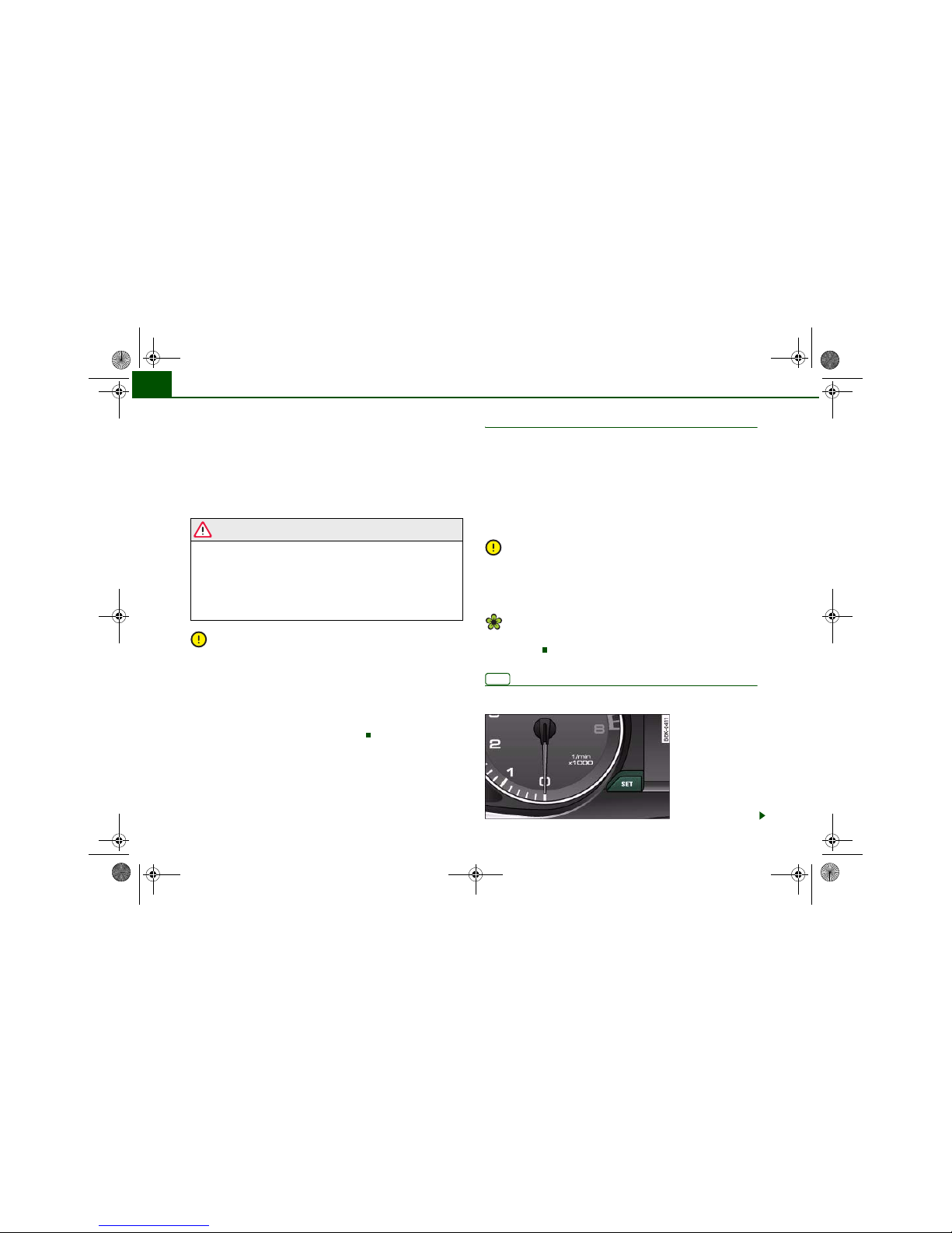
button
This button has a number of different functions.
A
2
SET
Fig. 3 Ins trument
cluster: SET button
document_0900452a81b1b9de.book Seite 12 Donnerstag, 26. Juli 2007 9:16 09
Instruments and warning/indicator lamps 13
Controls Safety Driving tips General maintenance Self-help Technical data
The button has the following functions:
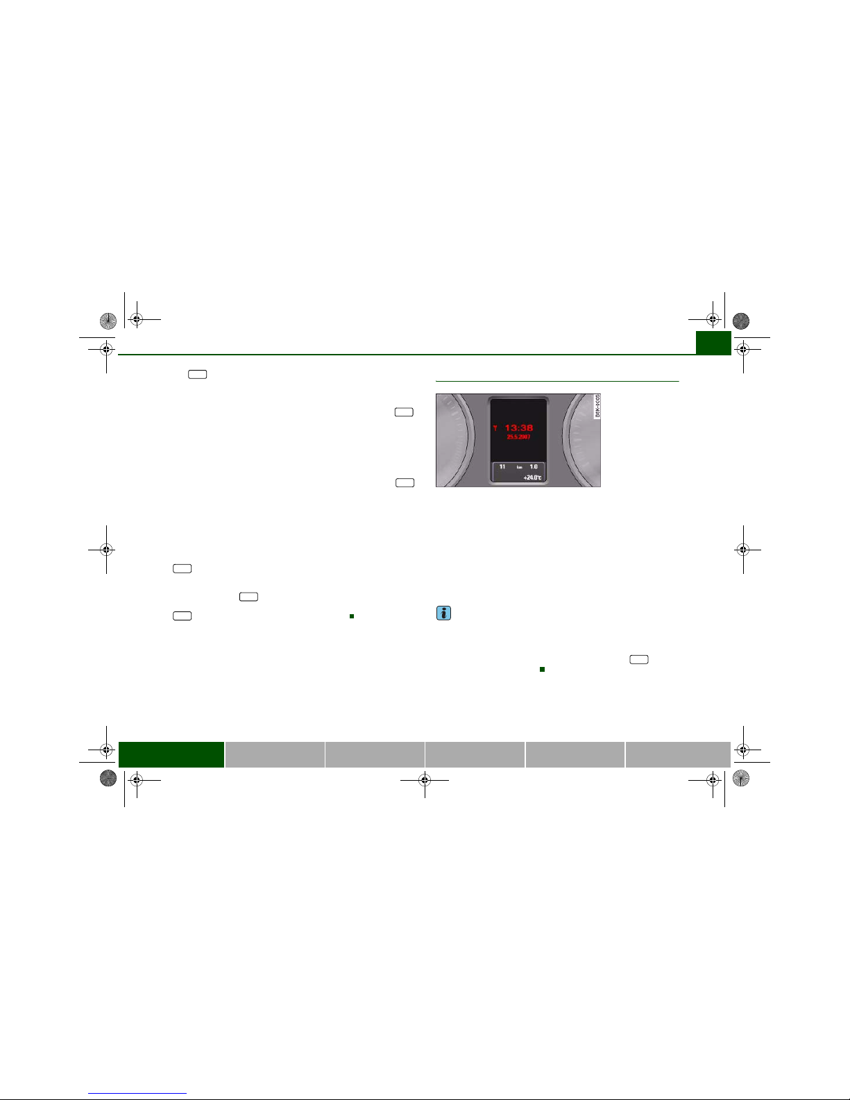
Activating clock, date, temperature and mileage
recorder displays
The display will appear for about 30 seconds if you press the
button ⇒ page 12, fig. 3 when the ignition is switched off.
Starting check procedure (auto-check control)
The auto-check control checks important components and vehicle
systems. These background checks are run constantly, as long as
the ignition is switched on ⇒ page 30.
You can start the “check procedure” manually by pressing the
button with the ignition switched on. This function check can be
started at road speeds up to 5 km/h.
Calling up driver messages again
A red or yellow symbol appearing in the instrument cluster display
is normally accompanied by a corresponding message. The
message will disappear from the display after about 5 seconds. If
required, you can call up the message again by briefly pressing the
button.
Setting speed warning
You can press the button briefly to set speed limit warning 1
while the vehicle is moving ⇒ page 29. If you press and hold the
button, this will cancel the speed warning.
Time and date display
Quartz clock
The date, time and display format can be changed using the sound
system or MMI* control console. Please refer to the sound system
or MMI* Operating Manual for more details.
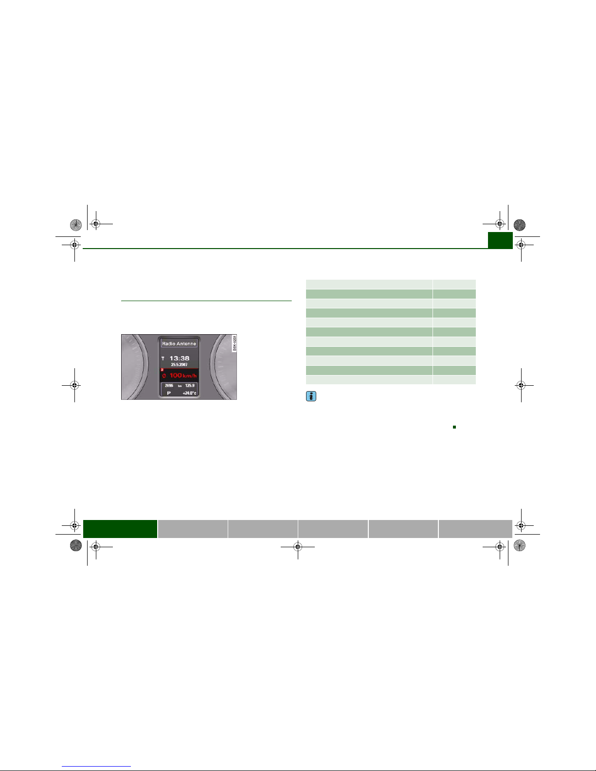
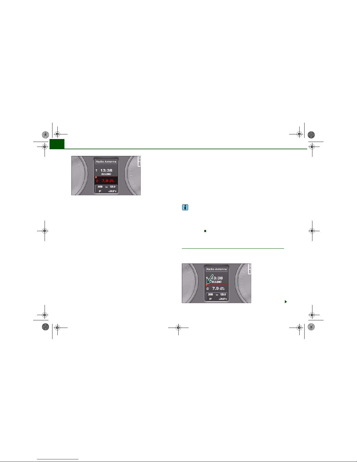
Radio-controlled clock*
When the clock is in “radio-control” mode the signal reception
symbol (a radio tower with radio waves) appears in the display
⇒ fig. 4. It is then not possible to change the minutes or the date
manually.
Note
• The digital clock and mileage recorder displays are switched on
for about 30 seconds when the driver's door is opened.
• When the ignition is switched off, the clock and date display can
be switched on for about 30 seconds by pressing the button
⇒ page 12, fig. 3 ⇒ page 12.
SET
SET
SET
SET
SET
SET
Fig. 4 In strument
cluster: Time and date
display
SET
document_0900452a81b1b9de.book Seite 13 Donnerstag, 26. Juli 2007 9:16 09
Instruments and warning/indicator lamps14
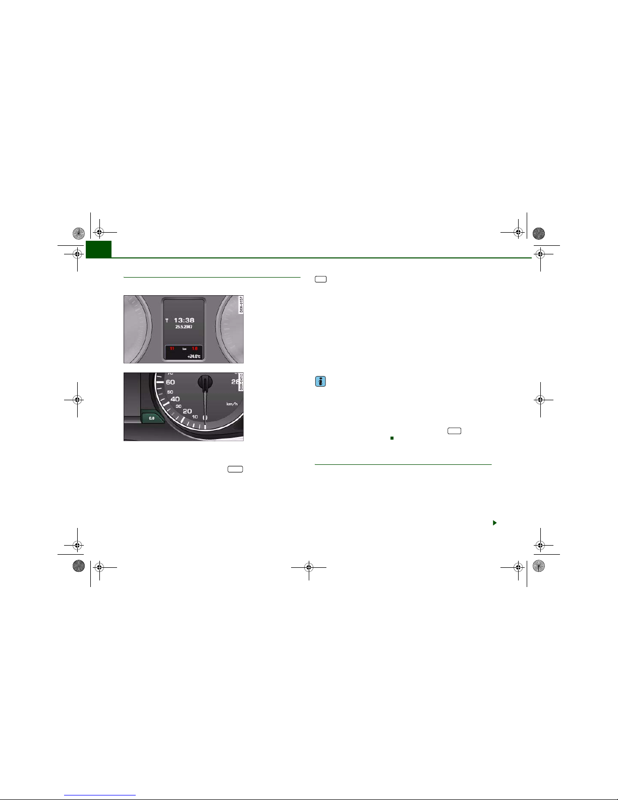
Mileage recorder
The instrument shows how far you have travelled.
The mileage is stated in kilometres (“km”) or “miles”.
You can switch the display from kilometres to miles and vice versa
via the sound system or MMI* using the button on the control
console.
Odometer / trip recorder
The odometer records the vehicle's total mileage.
The trip recorder shows the distance that has been travelled since it
was last reset. It is used to measure individual journeys. The last
digit of the trip recorder indicates distances of 100 metres or tenths
of a mile.
The trip recorder can be reset to zero by pressing the reset button
⇒ fig. 6.
Fault display
If there is a fault in the instruments, the letters dEF appear permanently in the trip recorder display. Please have the fault rectified as
soon as possible.
Immobiliser
When the ignition is switched on, the security programming of the
ignition key is verified electronically.
If an uncoded key is used, SAFE will appear continuously in the
mileage recorder display. The vehicle cannot then be driven
⇒ page 43.
Note
• The date, time and recorded mileage will continue to be
displayed for about 30 seconds after you switch off the ignition.
• The digital clock and mileage recorder displays are switched on
for about 30 seconds when the driver's door is opened.
• When the ignition is switched off, the mileage recorder can be
switched on for about 30 seconds by pressing the button
⇒ page 12, fig. 3 ⇒ page 12.
Fuel gauge
The gauge only works when the ignition is switched on.
When the needle reaches the reserve zone, the symbol ⇒ page 37
lights up in the instrument cluster display together with the
message Please refuel. At this point there are still about 8 litres of
fuel left in the tank. This is your reminder to fill up soon.
The tank capacity of your vehicle is given in the Technical data
section.
Fig. 5 In strument
cluster: Mileage
recorder
Fig. 6 In strument
cluster: Reset button
CAR
0.0
SET
document_0900452a81b1b9de.book Seite 14 Donnerstag, 26. Juli 2007 9:16 09
Instruments and warning/indicator lamps 15
Controls Safety Driving tips General maintenance Self-help Technical data
Caution
Never run the tank completely dry. The irregular supply of fuel can
cause misfiring, which would allow unburnt fuel to enter the
exhaust system. This can lead to overheating and damage to the
catalytic converter.
Warning and indicator lamps
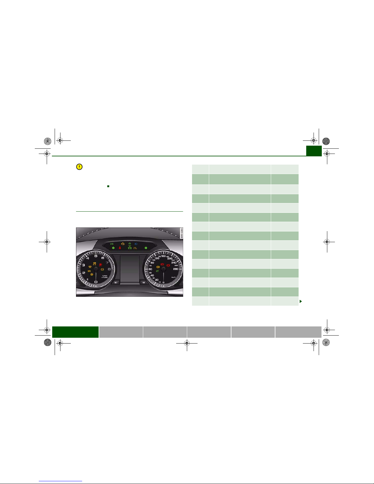
Overview
The warning and indicator lamps indicate a number of
different functions and possible faults.
Fig. 7 Instrument cluster with warning and indicator lamps
Dynamic steering ⇒ page 16
Engine management (alternative
to )
⇒ page 16
(alternative to )
⇒ page 16
Electronic stabilisation program (ESP) ⇒ page 17
Airbag system ⇒ page 17
Tyre pressure monitoring ⇒ page 17
Left turn signals ⇒ page 18
Trailer turn signals* ⇒ page 18
Seat belt warning lamp ⇒ page 18
Emission control system ⇒ page 18
lane assist (active) ⇒ page 18
lane assist (inactive) ⇒ page 18
Main beam headlights ⇒ page 18
Right turn signals ⇒ page 18
Cruise control system* ⇒ page 19
document_0900452a81b1b9de.book Seite 15 Donnerstag, 26. Juli 2007 9:16 09
Instruments and warning/indicator lamps16
Additional warning and indicator lamps are displayed on vehicles
equipped with the adaptive cruise control* ⇒ page 134.
Note
A number of functions are monitored by the auto-check control
⇒ page 21. If a malfunction should occur, this will be shown by the
display in the instrument cluster either with a red symbol (prio rity 1
– serious malfunction) or a yellow symbol (priority 2 – other
malfunction or item requiring attention).
Applies to vehicles: with Audi drive select
Dynamic steering
If the warning lamp lights up when you switch on the ignition and
goes out when the engine has started, the dynamic steering is activated.
If the warning lamp stays on after the engine has started, this
indicates a malfunction in the system. You can continue driving
carefully at reduced speed to the next qualified workshop, howeve r
the steering may feel heavier and its response may be more sensitive than usual. In addition, it is possible that the steering wheel will
be off centre when driving in a straight line.
WARNING
Have the system malfunction in the dynamic steering repaired by
a qualified workshop as soon as possible – risk of accident.
Note
• If the warning lamp flashes, this indicates that the dynamic
steering is being initialised. The message “Dynamic steering: Initialising” ⇒ page 36 will appear in the driver information system
display.
• The stabilisation functions of the dynamic steering ⇒ page 222
are not available in the event of a system malfunction.
Applies to vehicles: with petrol engine
Engine management
This warning lamp monitors the engine management
system on petrol engines.
The warning lamp (Electronic Power Control) lights up when the
ignition is switched on to show that the lamp is working properly.
Note
If the warning lamp lights up while the vehicle is moving, this indicates a fault in the engine management system. The engine should
be serviced by a qualified workshop without delay.
Applies to vehicles: with diesel engine
Glow plug system
The indicator lamp lights up to show that the glow plugs
are preheating.
Your vehicle is equipped with an automatic glow plug system.
The indicator lamp lights up while the glow plugs are preheating.
If the engine fails to start immediately, the glow plugs have not
finished preheating. In this case, keep the clutch pedal depressed
(or keep your foot on the brake if your vehicle has an automatic
gearbox) until the engine starts.
Anti-lock brake system (ABS) ⇒ page 19
Electro-mechanical parking
brake/Audi hold assist*
⇒ page 20
Fault in brake system ⇒ page 20
document_0900452a81b1b9de.book Seite 16 Donnerstag, 26. Juli 2007 9:16 09
Instruments and warning/indicator lamps 17
Controls Safety Driving tips General maintenance Self-help Technical data
Note
• If the glow plug indicator lamp should start flashing while the
vehicle is moving, this indicates a fault in the engine management
system. The engine should be serviced without delay.
• If the indicator lamp fails to light up when the ignition is
switched on, this can mean that the glow plug system is defective.
The engine should be serviced.
Electronic stabilisation program (ESP)
This warning lamp monitors the electronic stabilisation
program.
The warning lamp has the following functions:
• It flashes when the ESP or traction control system (ASR) inter-
venes while the vehicle is in motion.
• The warning lamp will light up continuously if the ESP or the
traction control system (ASR) has been switched off using the ESP
OFF button ⇒ page 222.
• It lights up when the ignition is switched on and should go out
again after about 2 seconds. This signals that the lamp is working
properly.
• It will light up continuously if there is a malfunction in the ESP.
• It will also come on if a fault should occur in the ABS bec ause the
ESP operates in conjunction with the ABS.
If the battery has been disconnected, if the battery voltage is very
low, or if the engine has been started from an outside power source,
the ESP system will perform an initialisation of the various on-board
sensors while you drive the first few metres. The warning lamp will
light up during this period. It will go out when the initialisation has
been completed.
If the warning lamp lights up and stays on after the engine is
started, this may mean that the control system has temporarily
switched off the ESP. In this case the ESP can be reactivated by
switching the ignition off and then on again. If the warning lamp
goes out, this means the system is fully functional.
For further information on the ESP ⇒ page 222.
Airbag system
This warning lamp monitors the airbag and seat belt
tensioner system.
The warning lamp should light up for a few seconds when the
ignition is switched on.
If the warning lamp does not go out, or if it lights up, flashes or
flickers when the vehicle is moving, this indicates a malfunction in
the system. This is also the case if the warning lamp does not light
up when the ignition is switched on.
WARNING
If a malfunction should occur, have the system checked immediately by a qualified workshop. If this is neglected, there is a risk
that the airbag system and/or belt tensioners may not be activated in an accident.
Tyre pressure monitoring
The tyre pressure should be corrected as soon as possible
if it is too low.
If the symbol flashes for about a minute and then remains lit after
you switch on the ignition, there is a fault in the system. Please
contact the nearest qualified workshop as soon as possible.
For more detailed information on the tyre pressure monitoring
system, please refer to ⇒ page 39.
document_0900452a81b1b9de.book Seite 17 Donnerstag, 26. Juli 2007 9:16 09
Instruments and warning/indicator lamps18
Turn signals
Depending on which turn signal is operated, either the left or
right indicator lamp flashes. Both indicator lamps will flash when
the hazard warning lights are switched on.
If one turn signal should fail, the indicator lamp will start flashing
twice as fast.
This does not apply when towing a caravan or trailer. The indicator
lamp will stop flashing if one of the turn signals on the vehicle or the
caravan/trailer should fail. For further information on the turn
signals ⇒ page 62.
Applies to vehicles: with towing bracket
Trailer turn signals
The indicator lamp flashes when the turn signals are
operated while towing a caravan or trailer.
The indicator lamp flashes when the turn signals are operated,
provided a caravan or trailer is correctly attached and connected to
the vehicle.
The indicator lamp will not flash if one of the turn signals on the
trailer fails.
Seat belt warning lamp
The warning lamp acts as a reminder to fasten the seat
belts.
After switching on the ignition, the warning lamp will remain lit
until the driver and front passenger (if applicable) have fastened
their seat belts. When the vehicle has gathered speed you will also
hear a warning chime.
For further information on the seat belts ⇒ page 194.
Emission control system
If the warning lamp lights up continuously you should take your
vehicle to a qualified workshop as soon as possible in order to have
the fault rectified.
If the warning lamp flashes drive on at reduced speed and seek
professional help in order to avoid damage to the catalytic
converter.
For further information on the catalytic converter ⇒ page 229.
Applies to vehicles: with lane assist
lane assist (active)
The indicator lamp confirms that the system is fully functional. You
will be warned if you are about to cross the lane markings detected
by the system.
For more information on the lane assist system, please see
⇒ page 145.
lane assist (inactive)
The warning lamp indicates that the system is switched on.
However, you will not be warned if you cross the lane markings.
For more information on the lane assist system, please see
⇒ page 145.
Main beam headlights
The indicator lamp lights up when the main beams are on or
when the headlight flasher is operated.
For further information on the main beam headlights ⇒ page 62.
document_0900452a81b1b9de.book Seite 18 Donnerstag, 26. Juli 2007 9:16 09
Instruments and warning/indicator lamps 19
Controls Safety Driving tips General maintenance Self-help Technical data
Applies to vehicles: with cruise control system
Cruise control
The indicator lamp in the instrument cluster lights up when the
cruise control system is operating.
Anti-lock brake system (ABS)
The warning lamp monitors the ABS and the electronic
differential lock (EDL).
The warning lamp lights up for a few seconds when the ignition
is switched on and while the engine is being started. The lamp goes
out again once the system has run through an automatic test
sequence.
There is a fault in the ABS if:
• the warning lamp does not light up when the ignition is
switched on,
• the warning lamp does not go out again after a few seconds,
• the warning lamp lights up when the vehicle is moving.
The vehicle can still be braked in the normal way (except that the
ABS control function is out of action). Please take the vehicle to a
qualified workshop as soon as possible. For further information on
the ABS ⇒ page 222.
If a fault occurs in the ABS, the ESP warning lamp will also light up.
Fault in the main brake system
If the ABS warning lamp lights up together with the brake
warning lamp ⇒ page 32, this indicates a fault in the ABS function, and possibly a malfunction in the main brake system as well
⇒ .
If there is a malfunction in the brake system the symbol will light
up in the instrument cluster. Please refer to ⇒ page 32.
Fault on the electronic differential lock (EDL)
The EDL works in conjunction with the ABS. If a malfunction should
occur in the EDL, this is indicated by the ABS warning lamp .
Please take the vehicle to a qualified workshop as soon as possible.
For further information on the EDL ⇒ page 222.
WARNING
• Before opening the bonnet and checking the brake fluid level,
observe the warning information on ⇒ page 255, “Working on
components in the engine compartment”.
• If the brake warning lamp should light up together with the
ABS warning lamp , stop the vehicle immediately and check the
brake fluid level in the reservoir. If the fluid level has dropped
below the "MIN" mark you must not drive on - otherwise there may
be an increased accident risk. You should obtain professional
assistance.
• If the brake fluid level is OK, the fault in the brake system may
have been caused by a failure of the ABS control function. As a
result the rear wheels can lock relatively easily when braking. This
could cause the tail of the vehicle to skid sideways. Drive carefully
to the nearest qualified workshop and have the fault rectified.
Applies to vehicles: with Audi hold assist
Audi hold assist
This warning lamp monitors the Audi hold assist function.
Audi hold assist helps the driver to keep the vehicle stationary while
the engine is running, for instance on steep gradients, at traffic
lights or in stop-and-go traffic. When the Audi hold assist function
is on, you don't have to keep your foot on the brake to prevent the
vehicle from accidentally rolling away. Once it detects that the
vehicle is stopped, Audi hold assist keeps the vehicle stationary. The
green symbol in the instrument cluster indicates that the function is activated. You can now take your foot off the brake pedal.
document_0900452a81b1b9de.book Seite 19 Donnerstag, 26. Juli 2007 9:16 09
Instruments and warning/indicator lamps20
When the vehicle has been stationary for an extended period, Audi
hold assist will automatically apply the parking brake. In this case,
the green symbol will change to red .
Electro-mechanical parking brake
This warning lamp monitors the electro-mechanical
parking brake.
The warning lamp lights up when the parking brake is applied
with the ignition on. After the ignition has been switched off the
lamp will stay on for about 30 seconds. The warning lamp will light
up for about 30 seconds if the parking brake is applied with the ignition switched off.
The warning lamp should go out when the parking brake is released.
If the warning lamp flashes continuously after the parking brake has
been applied, the brake may not be strong enough to hold the
vehicle on a slope. This may be due to the brakes overheating.
Please note the following points:
• If the gradient is too steep to park the vehicle safely, the display
will show the message Caution: Vehicle parked too steep.
• In the event of a fault in the parking brake system the symbol
will also appear in the instrument cluster display together with the
message Parking brake! You should have the fault corrected by a
qualified workshop without delay.
Brake system
The warning lamp flashes if the brake fluid level is too low
or if there is a fault in the ABS system or the parking
brake.
If the warning lamp flashes, there is a fault in the brake system.
The symbo l in the instrument cluster display will flash at the
same time. You can press the button to obtain a message
explaining the fault ⇒ page 32.
If a failure should occur in the ABS, the ABS warning lamp will
light up together with the brake warning lamp ⇒ .
WARNING
• Before opening the bonnet and checking the brake fluid level,
observe the warning information on ⇒ page 255, “Working on
components in the engine compartment”.
• If the brake warning lamp does not go out, or if it lights up
when driving, the brake fluid level in the reservoir is too low – this
may cause an increased accident risk. Stop the vehicle and do not
drive on. You should obtain professional assistance.
• If the brake warning lamp lights up together with the ABS
warning lamp, this can mean that the control function of the ABS
is out of action. As a result the rear wheels can lock relatively
easily when braking. This could cause the tail of the vehicle to skid
sideways. Drive carefully to the nearest qualified workshop and
have the fault rectified.
SET
document_0900452a81b1b9de.book Seite 20 Donnerstag, 26. Juli 2007 9:16 09
Driver information system 21
Controls Safety Driving tips General maintenance Self-help Technical data
Driver information system
Introduction
General notes
The driver information system in the instrument cluster
shows you the status of various on-board systems at a
glance.
The display for the driver information system is in the centre of the
instrument cluster.
The system runs a check on certain components and functions
when the ignition is switched on and while the vehicle is moving. It
gives an audible warning if a fault should occur or if servicing is
required, and a red or yellow warning symbol (in some cases with a
corresponding driver message) appears in the dashboard display.
The system will also display information for the radio and CD player
and (if fitted) the route guidance directions from the navigation
system*. For further information on these systems, please refer to
the sound system or MMI* Operating Manual.
On some models the display of information shown in the instrument cluster differs from the illustrations used here.
The driver information system includes the following functions:
Note
If a fault should occur, the display will show a red or yellow warning
symbol. A red warning symbol indicates a serious malfunction
⇒ page 31. A yellow warning symbol indicates a less serious
malfunction, or other item requiring attention ⇒ page 35.
Fig. 8 Dashboard:
Display in instrument
cluster (automatic
gearbox)
CD and radio display ⇒ page 22
Outside temperature ⇒ page 22
Gear-change indicator ⇒ page 22
Digital speedometer* ⇒ page 23
Door catches/boot lid warning ⇒ page 24
Service interval display ⇒ page 24
Auto-check control* ⇒ page 30
Driver messages ⇒ page 30
Speed warning ⇒ page 28
On-board computer* ⇒ page 25
Selector lever positions for automatic gearbox* ⇒ page 163
document_0900452a81b1b9de.book Seite 21 Donnerstag, 26. Juli 2007 9:16 09
Driver information system22
CD and radio display
If no priority 1 or 2 faults have been detected by the auto-check
control, the name or frequency of the current radio station and the
selected waveband will appear the upper part of the display.
When a CD is playing, the display will show the current title. If the
vehicle is equipped with a CD changer* the display will also show
the number of the CD being played (CD1 to CD6).
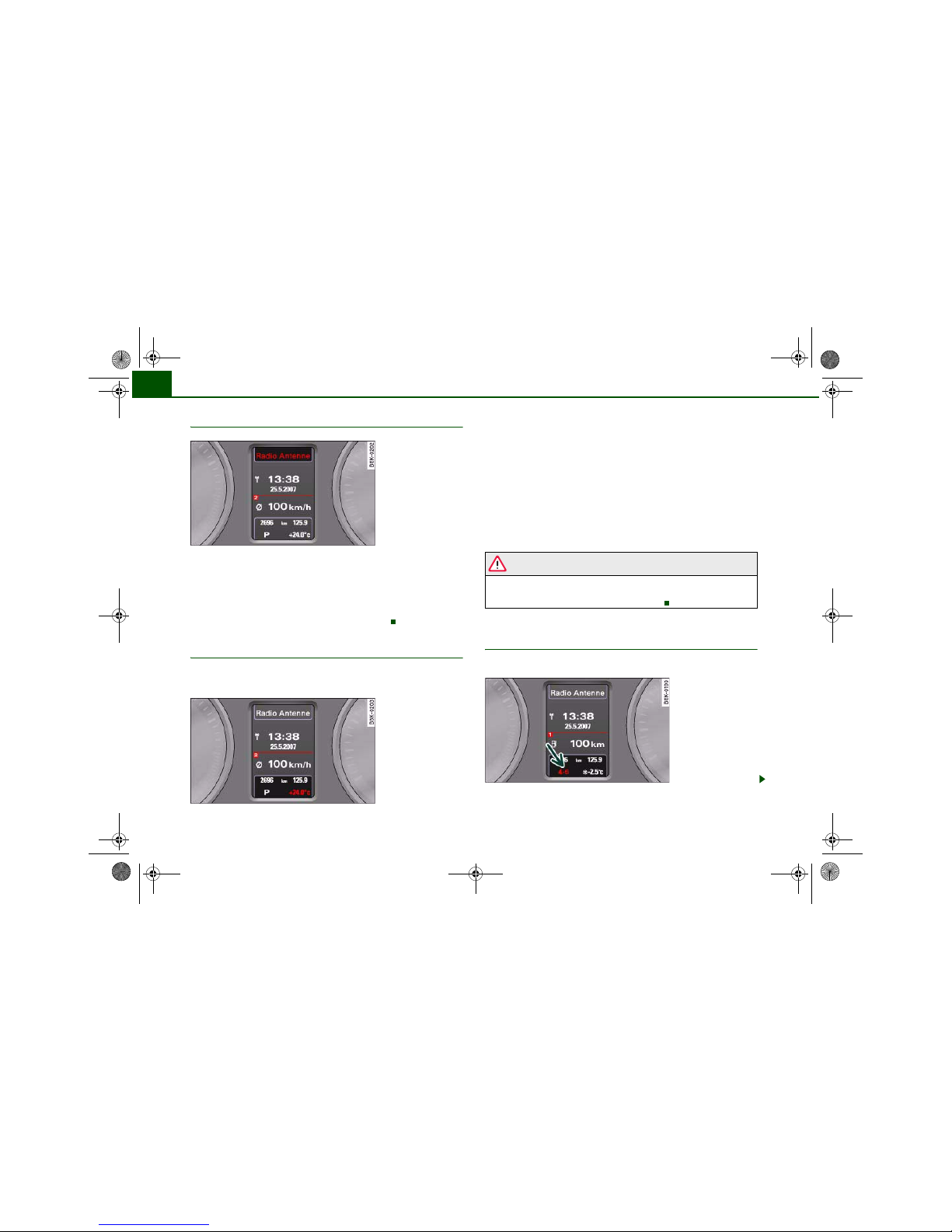
Outside temperature display
The outside temperature is shown when the display is
activated.
At temperatures below +5°C a snowflake symbol appears next to the
temperature display. This is to warn the driver to take extra care
when there is a risk of ice on the road.
When the vehicle is stationary or travelling at very low speeds, the
temperature displayed may be slightly higher than the actual
outside temperature as a result of the heat radiated from the
engine.
The temperature units can be set to °F or °C on the sound system or
MMI* system. The outside temperature is automatically displayed in
the units you have selected. Please refer to the sound system or
MMI* Operating Manual for further details.
WARNING
Do not rely on the outside temperature display as an ice warning.
Please bear in mind that there may be patches of ice on the roads
even at outside temperatures around +5°C.
Applies to vehicles: with manual gearbox an d gear-change indicator
Gear-change indicator
This additional indicator function can help to save fuel.
Fig. 9 Di splay: Radio
information
Fig. 10 Di splay:
Outside temperature
Fig. 11 Display: Gearchange indicator
document_0900452a81b1b9de.book Seite 22 Donnerstag, 26. Juli 2007 9:16 09
Driver information system 23
Controls Safety Driving tips General maintenance Self-help Technical data
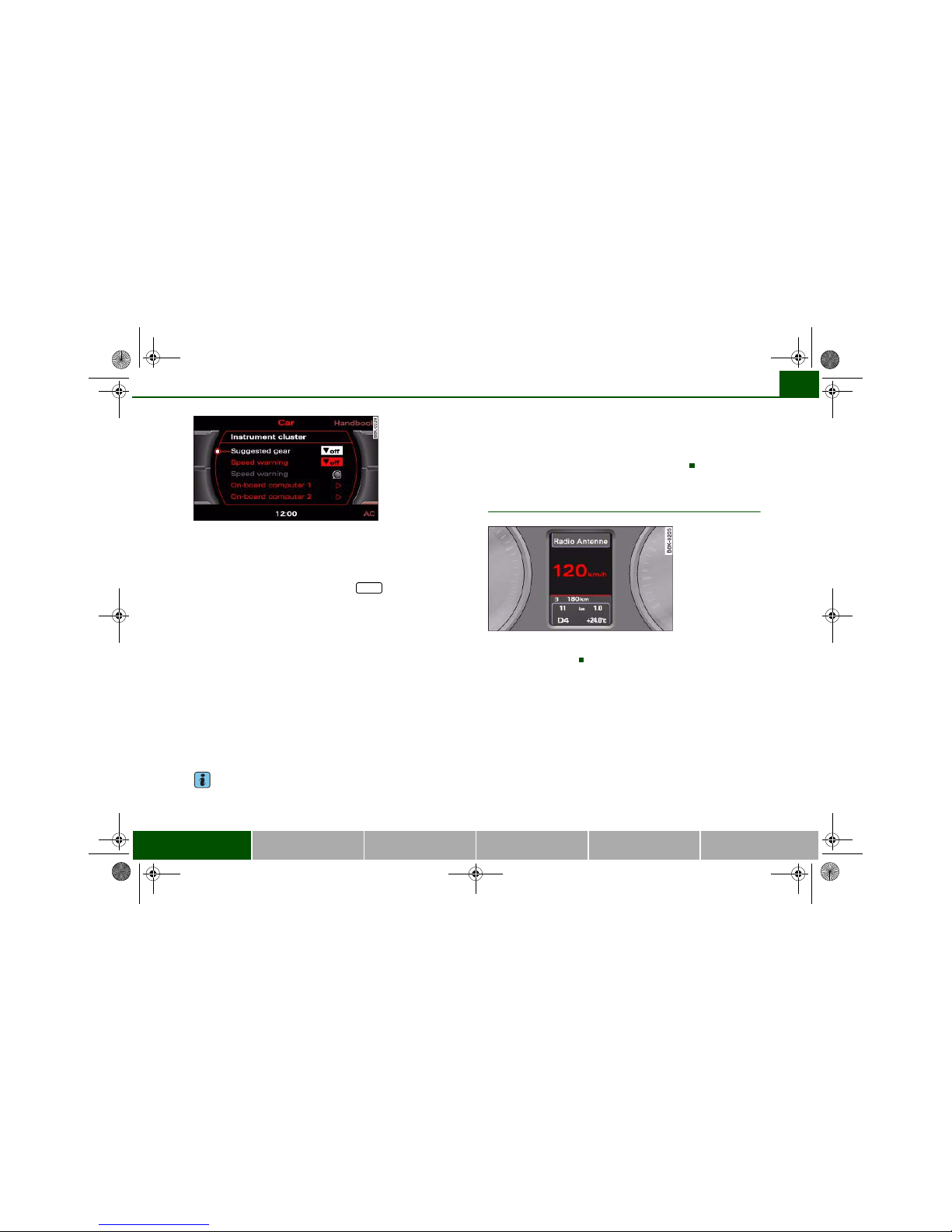
You can activate and deactivate the gear-change indicator
on the sound system or MMI*.
Switching the gear-change indicator on and off
– Select: Function selector button > Instrument
cluster > Suggested gear ⇒ fig. 12.
To familiarise yourself with the gear-change indicator, we recommend driving in the normal way to start with. A gear change will be
recommended if the gear you are in is not the most economical
choice. The gear you are currently in and the recommended gear
will be displayed ⇒ page 22, fig. 11.
• Shifting up a gear: The suggested gear appears to the right of the
current gear when a higher gear is recommended.
• Shifting down a gear: The suggested gear appears to the left of
the current gear when a lower gear is recommended.
Gears may ocassionally be skipped (3 > 5). If no gear-change is
recommended, you are already in the most economical gear.
Note
• The gear-change indicator is intended to help save fuel. It is not
intended to recommend the right gear for all driving situations. In
certain situations, only the driver can choose the correct gear (for
instance when overtaking, driving up a steep gradient or towing a
trailer).
• The gear-change indicator in the instrument cluster ⇒ page 22,
fig. 11 goes out when you press the clutch pedal.
Applies to vehicles: with on-board computer
Digital speedometer
The display shows the current speed. The speed is displayed in
increments of 1 km/h.
Fig. 12 Di splay:
Switching the gear
change indicator on
and off
CAR
Fig. 13 Display: Digital
speedometer
document_0900452a81b1b9de.book Seite 23 Donnerstag, 26. Juli 2007 9:16 09
Driver information system24
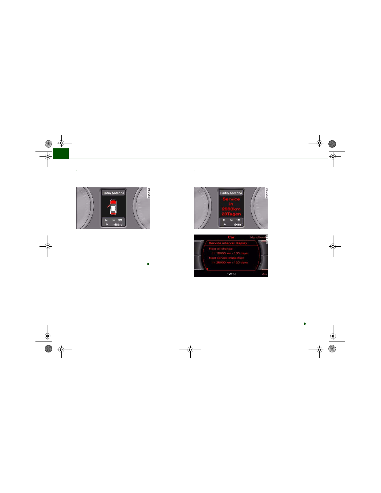
Door catches / boot lid warning
The pictogram shows whether the doors and the boot lid,
etc. are properly closed when driving off.
The door catches/boot lid warning symbol lights up if one or more
of the doors, or the bonnet or boot lid are not properly closed when
the ignition is on. The symbol also indicates which of these is not
properly closed ⇒ fig. 14.
The warning symbol disappears when all the doors, the bonnet and
the boot lid are completely closed, and the driver information functions selected will then be displayed again.
Service interval display
The service interval display detects when the next service
is due for your vehicle.
You can see whether an oil change or service inspection is due in
the Car menu on the sound system or MMI display. There are two
display levels:
• Service reminder: When the next service date is approaching,
Service in----- km--- days ⇒ fig. 15 will be shown in the instrument
cluster display each time you switch on the ignition. The number of
days and kilometres act independently of each other. Service due!
will appear in the display when the number of days reaches zero,
even if you have not yet driven the estimated number of kilometres
remaining. Similarly, Service due! will appear in the display when
Fig. 14 Di splay: Door
catches/boot lid
warning
Fig. 15 In strument
cluster display: Service
interval display
Fig. 16 Di splay:
Service interval displa
y
document_0900452a81b1b9de.book Seite 24 Donnerstag, 26. Juli 2007 9:16 09

Driver information system 25
Controls Safety Driving tips General maintenance Self-help Technical data
the number of kilometres reaches zero, even if the estimated period
has not yet expired. The remaining distance and time are updated
and displayed briefly each time you switch on the ignition.
• Service due: When a service is due, Service due! will appear in
the display as soon as you switch on the ignition. The display reverts
back to the standard display after a short time. In addition, a tone
will sound.
Displaying distance and time to next service
In the Car menu, you can look up the distance and time remaining
until the next oil change and next service inspection. To do this,
select function selector button > Service interval display
⇒ page 24, fig. 16.
The display may not be complete on new vehicles within the first
500 km.
Resetting the service interval display
Your Audi dealer resets the display after each service. You can only
reset the oil change display yourself. To do this, select function
selector button > Service interval display > Reset oil change
interval. The next oil change will be indicated as being due
15,000 km or one year (fixed service interval) after the oil change
interval is reset.
Caution
The system cannot calculate the figures for the service indicator if
the battery is disconnected from the vehicle, so no service reminder
can be displayed during this time. Please remember that keeping to
the correct service intervals is most important for the service life
and residual value of the vehicle (and especially for the life of the
engine). The period between two services must never be longer
than the time specified in the Service Schedule, even if you only
cover a low mileage during this time.
Note
• Do not reset the display between oil changes - otherwise the
display will be incorrect.
• The information in the service interval display remains intact if
the battery is disconnected.
• The distance to the next service cannot be called up if the system
has detected a Priority 1 fault (red symbol).
• If the service was not performed by a qualified w orkshop, the oil
change interval display can only be set to “fixed service intervals” of
15,000 km. If you wish to continue with the “LongLife” service, you
will need to have the oil change interval display reset by a qualified
workshop.
On-board computer
Applies to vehicles: with on-board computer
Introduction
The on-board computer provides you with useful information during a journey, including average and current fuel
consumption, average speed, fuel range and driving time.
CAR
CAR
Fig. 17 On -board
computer: Fuel range
document_0900452a81b1b9de.book Seite 25 Donnerstag, 26. Juli 2007 9:16 09
Driver information system26
The following items of information are processed by the on-board
computer and can be shown one after the other on the display in the
instrument cluster.
Fuel range
The estimated fuel range is displayed in km. It shows how far the
vehicle can be driven with the amount of fuel left in the tank,
assuming the same style of driving. The fuel range is displayed in
increments of 10 km.
The fuel range is calculated on the basis of the fuel consumption
over the last 30 kilometres. The fuel range will increase accordingly
if you drive in a more economical manner.
Average fuel consumption
This mode displays the average fuel consumption since the memory
was last cancelled in litres/100 km. If required, you can use this
display to adjust your driving style to achieve the desired fuel
consumption.
Current fuel consumption
The display shows the current fuel consumption in litres/100 km. If
required, you can use this display to adjust your driving style to
achieve the desired fuel consumption.
The computer calculates the fuel consumption every 30 metres. The
display switches to l/h (litres per hour) when the vehicle is
stationary.
Average speed
This mode shows the average speed driven since the memory was
last cancelled (in km/h).
Driving time
This display shows the period of time which has elapsed since the
memory was last cancelled.
Distance covered
This display shows the distance you have covered since the memory
was last cancelled.
Note
• The displays for fuel consumption (average and current
consumption), fuel range and speed are shown in metric units. You
can change the measurement units via the sound system or MMI*.
• The information in the memory is cancelled if the battery is
disconnected.
Applies to vehicles: with on-board computer
Memory
The on-board computer has two automatic journey
memories.
Fig. 18 On -board
computer: Average fuel
consumption
Fig. 19 On -board
computer: Memory 1
document_0900452a81b1b9de.book Seite 26 Donnerstag, 26. Juli 2007 9:16 09
Driver information system 27
Controls Safety Driving tips General maintenance Self-help Technical data
Press RESET button ⇒ fig. 20 to switch back and forward
between the functions of on-board computers 1 and 2.
The number in the display ⇒ page 26, fig. 19 indicates which of the
two memories is currently in use. The figure 1 means that the
display is showing the information in the single journey memory
(on-board computer 1). The figure 2 means that the display is
showing the information in the total journey memory (on-board
computer 2).
Single journey memory (on-board computer 1)
The single journey memory processes the information on a journey
from the time the ignition is switched on until it is switched off. If
the journey is resumed within two hours after the ignition is
switched off, the new figures are automatically included in the
calculation. The memory is automatically deleted whe n you resume
driving, if the journey is interrupted for more than two hours.
Total journey memory (on-board computer 2)
Unlike the single journey memory, the total journey memory is not
erased automatically. In this way, you can determine the period for
which you wish the on-board computer to supply figures.
Applies to vehicles: with on-board computer
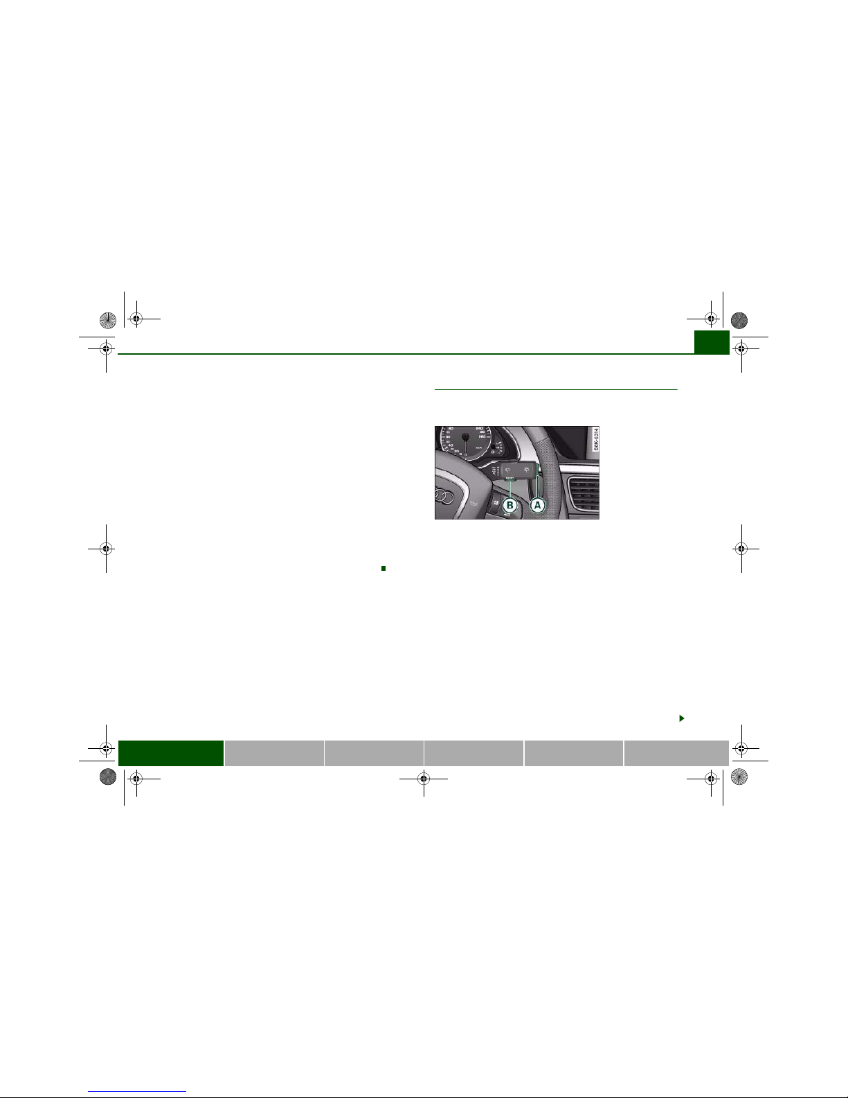
Controls
The on-board computer is controlled by means of two
switches on the windscreen wiper lever.
– Press the top or bottom of the function selector switch
⇒ fig. 20. This displays the on-board computer read-
outs one after the other.
The on-board computer can only be operated while the ignition is
switched on. When the ignition is switched on, the display shows
the function that was last selected.
As well as the figures from the on-board computer (computer 1 or
2), the display can also show information from other systems. Press
the Reset button briefly to switch back and forward between
these displays.
Resetting figures to zero
To cancel one of the computer readings individually, select the
required function and press the RESET button for at least one
second. The following values can be reset to zero individually using
the Reset button:
• Average fuel consumption
• Average speed
A
B
Fig. 20 W indscreen
wiper lever: On-board
computer controls
A
A
ABA
B
document_0900452a81b1b9de.book Seite 27 Donnerstag, 26. Juli 2007 9:16 09
Driver information system28
• Driving time
• Distance covered
You can also cancel all the values in the single journey memory or
the total journey memory at the same time ⇒ page 28.
Note
The information in the memory is cancelled if the battery is
disconnected.
Applies to vehicles: with on-board computer
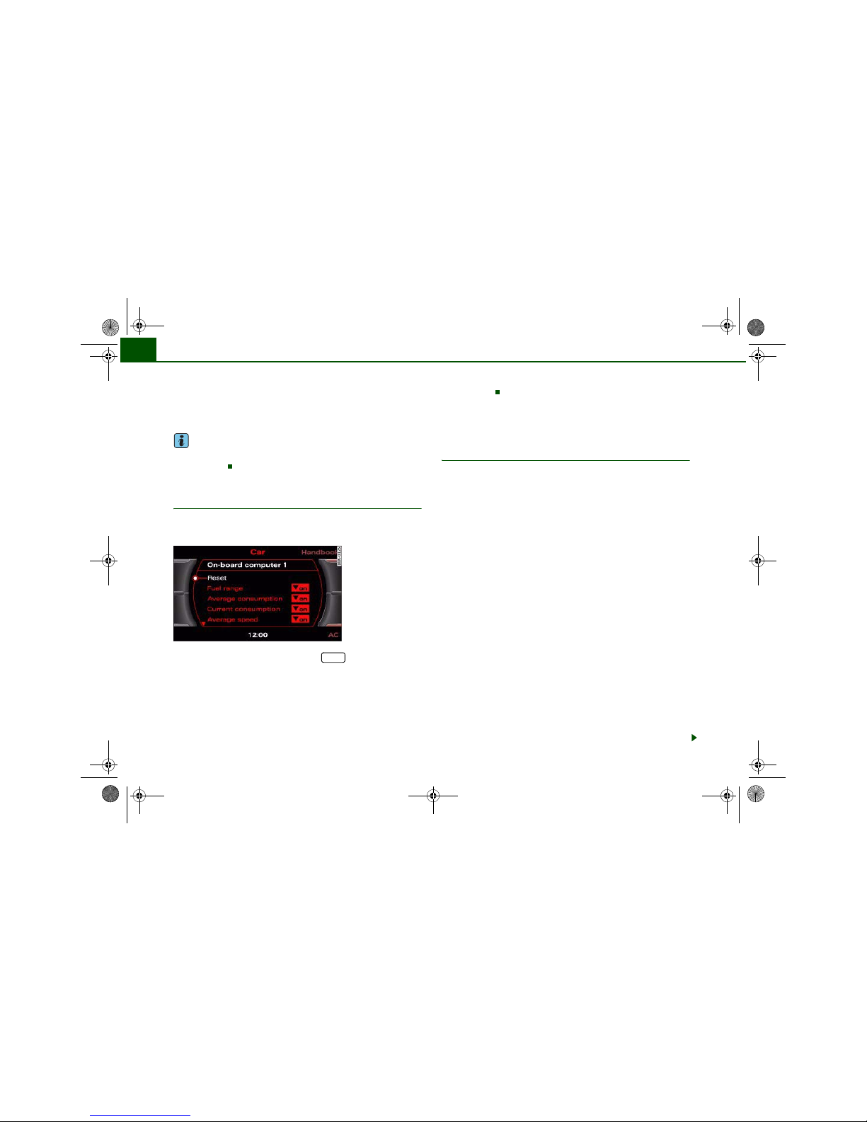
Basic settings for the on-board computer
The basic settings for the on-board computer can be
adjusted via the sound system or MMI*.
– Select: Function selector button > Instrument
cluster > On-board computer 1 or On-board computer 2.
You can zero all the values in the single journey memory or the total
journey memory at the same time by selecting the Reset menu item.
You can also define which items of information you wish to have
displayed by the on-board computer. If one of these items is
switched off, it will not appear in the display. However, the corresponding figures will still be registered by the on-board computer
and can be switched back on at any time so that they again appear
in the display.
Speed warning function
Applies to vehicles: with speed warning function
Introduction
The speed warning function can help you keep below a
pre-set maximum speed.
The speed warning function will warn you if the vehicle exceeds the
pre-set maximum speed. The system gives an audible warning
signal if the set speed is exceeded by about 3 km/h. A warning
symbol will also appear in the display . On some models the symbo l
may look slightly different.
The speed warning function has two different warning speeds,
which operate independently and serve slightly different purposes:
Speed limit warning 1
With speed limit warning 1, the maximum speed can be changed
while driving. The speed limit that has been set remains stored until
the ignition is switched off, or until it is changed or cleared.
The speed limit warning symbol for speed limit warning 1 will
appear in the display if you exceed the pre-set speed. It goes out
again if the speed is reduced below the set speed limit.
The symbol also goes out if the speed is increased to more than
about 40 km/h above the set speed for at least 10 seconds. This
cancels the speed limit that was originally set.
Setting speed limit warning 1 ⇒ page 29.
Speed limit warning 2
You are recommended to store this speed limit warning if you
always wish to be reminded of a particular speed limit. This could
be when driving in countries with general speed limits, or if you
Fig. 21 MMI display:
On-board computer
CAR
document_0900452a81b1b9de.book Seite 28 Donnerstag, 26. Juli 2007 9:16 09

Driver information system 29
Controls Safety Driving tips General maintenance Self-help Technical data
need to keep below a particular speed when winter tyres are fitted,
etc.
The speed limit warning symbol for speed warning 2 will appear
in the display if you exceed the pre-set speed. Unlike speed limit
warning 1, the warning symbol only goes out once the road speed
has dropped below the stored value again.
Setting speed limit warning 2 ⇒ page 29.
Note
Please bear in mind that, even with the speed warning function, it is
still important to keep a check on the car's speed with the speedometer and to observe the statutory speed limits.
Applies to vehicles: with speed warning function
Setting speed limit warning 1
You can use the button to set, alter or cancel speed
limit warning 1.
Selecting speed limit
– Drive at the desired maximum speed.
– Press the bu tton in the instrument cluster ⇒ fig. 22
for one second.
Clearing speed limit
– Drive the vehicle at a minimum of 5 km/h.
– Press the button for at least 2 seconds.
The speed warning symbol lights up briefly in the display to
confirm that the selected speed has been stored. The speed limit
that has been set remains stored until another speed is set with a
brief push of the button, or until the memory is cleared with a long
push of the button.
When the speed limit has been cleared, the display will show a
crossed-out warning symbol .
Applies to vehicles: with speed warning function
Setting speed limit warning 2
You can use the sound system or MMI* to set, alter or
cancel speed limit warning 2.
– Select: Function selector button > Instrument
cluster > Speed warning.
• Speed warning on/off - to activate or deactivate the speed
warning function ⇒ fig. 23.
SET
Fig. 22 Detail of the
instrument cluster:
SET button
SET
SET
Fig. 23 Di splay:
Setting speed limit
warning 2
CAR
document_0900452a81b1b9de.book Seite 29 Donnerstag, 26. Juli 2007 9:16 09

Driver information system30
• Speed warning - to set the speed above which a warning signal
will sound.
Speed limit warning 2 can be adjusted in increments of 10 km/h
between 30 and 240 km/h.
Auto-check control
Introduction
The auto-check control checks important components and vehicle
systems. These background checks are run constantly, as long as
the ignition is switched on.
A message is displayed in the instrument cluster if a fault should
occur or if any maintenance or repairs are urgently required. This is
accompanied by an audible warning signal. Depending on the
priority of the fault, a red or yellow warning symbol lights up in the
display.
The red symbols indicate a serious malfunction, whereas the yellow
ones represent other malfunctions or items requiring attention.
Additional messages to assist the driver may be shown with the red
or yellow symbols.
Automatic gearbox* function test
The auto-check control automatically checks the vehicle systems
when the ignition is switched on. If the selector lever is in position
P or N, the following instruction will appear:
When stationary apply footbrake while selecting gear
When a gear (R, D etc.) is selected, this message disappears and the
auto-check control function is displayed.
The driver message will disappear 30 seconds after switching on
the ignition or earlier, if there are other driver messages or malfunctions.
If one or more faults are detected, the driver information message
(as above) will disappear about 15 seconds after the engine has
been started and the appropriate fault symbol(s) will appear in the
display. The warning display will be accompanied by the corresponding warning chime.
Applies to vehicles: with speed warning function
Driver messages
Additional messages to assist the driver are displayed
together with the warning symbols in the instrument
cluster.
For example, the following driver message will a ppear if the selector
lever for the automatic gearbox* is not in position P when you
switch off the engine:
Shift to P, otherwise vehicle can roll away. Doors do not lock if
lever is not in P.
The ignition key can only be withdrawn when the selector lever is in
this position. Similar messages will be displayed if other functions
of this kind cannot be carried out.
Driver messages and red symbols
If a red warning symbol appears in the display, it will automatically
be accompanied by the corresponding driver message.
Fig. 24 In strument
cluster: SET button
document_0900452a81b1b9de.book Seite 30 Donnerstag, 26. Juli 2007 9:16 09

Driver information system 31
Controls Safety Driving tips General maintenance Self-help Technical data
For example, in the event of an oil pressure malfunction the oil pressure symbol will appear in the display. In addition, the following
message will appear:
Switch off engine and check oil level
The message will disappear from the display after about 5 seconds.
If required, the message can be called up again by briefly pressing
the button ⇒ page 30, fig. 24.
Driver messages and yellow symbols
If a yellow warning symbol appears in the display, it will automatically be accompanied by the corresponding driver message.
For example, if the symbol appears (windscreen washer fluid
low), the display will also show the message:
Please top up washer fluid
The message will disappear after a few seconds. If required, the
message can be called up again by briefly pressing the
button.
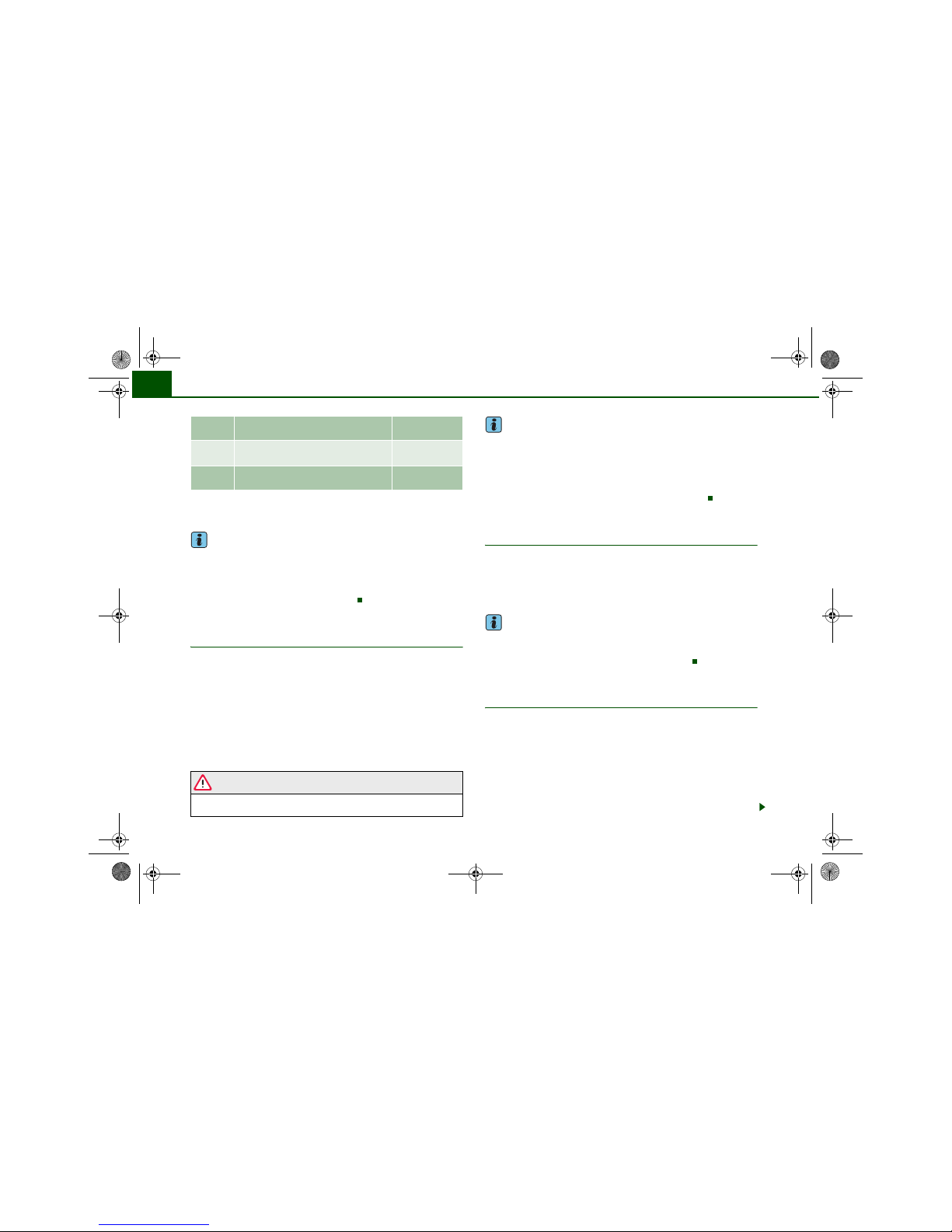
Red symbols
A red symbol warns of a serious malfunction.
–Stop the vehicle.
– Switch off the engine.
– Check the function displayed. Obtain professional assist-
ance if necessary.
The red symbols indicate a Priority 1 fault (serious malfunction).
Should a Priority 1 fault occur, a red warning symbol will appear at
the top of the display ⇒ fig. 25. The symbol is accompanied by a
driver message giving you more information about the fault. This
symbol is accompanied by three warning chimes. The symbol will
keep flashing until the fault is corrected.
If several Priority 1 faults are detected at the same time, the symbols
are displayed one after the other for about 2 seconds at a time.
This message will disappear after about 5 seconds, but you can call
it up again at any time by pressing the button ⇒ page 30.
SET
SET
Fig. 25 Di splay:
Symbol for serious
malfunction
Alternator fault ⇒ page 32
Fault in brake system/parking
brake
⇒ page 32
Coolant level too low / coolant
temperature too high
⇒ page 33
Engine oil pressure too low ⇒ page 33
Add engine oil immediately ⇒ page 34
Fault in the steering system ⇒ page 34
Ignition lock defective ⇒ page 34
Tyre pressure monitoring ⇒ page 39
SET
document_0900452a81b1b9de.book Seite 31 Donnerstag, 26. Juli 2007 9:16 09

Driver information system32
Alternator fault
If the symbol flashes in the instrument cluster display, there is an
alternator fault or a fault in the vehicle's electrical system. In addition, a message will appear. This message will disappear after about
5 seconds, but you can call it up again at any time by pressing the
button.
You should normally be able to drive to the next available qualified
workshop. However, you should avoid using electrical equipment
that is not absolutely necessary because this will drain the battery.
Caution
If the coolant warning lamp in the instrument display lights up
as well as the alternator warning lamp while driving ⇒ page 33, stop
the vehicle immediately and switch off the engine. In this case the
coolant pump is no longer being driven, and there is a risk of engine
damage.
Fault in the brake system
A fault in the brake system should be corrected as soon as
possible.
If the symbol flashes in the display, there is a fault in the
brake system. The symbol is accompanied by a driver
message giving you more information about the fault. This
message will disappear after about 5 seconds, but you can
call it up again at any time by pressing the button:
Stop vehicle and check brake fluid level
– Stop the vehicle.
– Check the brake fluid level ⇒ page 262.
– Obtain professional assistance if necessary.
Warning! Fault in ABS brake system. Contact
workshop
– Drive carefully to the nearest qualified workshop and
have the fault rectified ⇒ .
Parking brake ! Please contact workshop
– If the symbol appears after you switch on the ignition
when the vehicle is stationary, please check whether you
can release the parking brake. If this is possible, you
should drive without delay to the nearest qualified workshop and have the fault rectified. If the parking brake
cannot be released you should obtain professional
assistance.
– If this symbol should appear while driving, there may be
a malfunction in the drive-away assist or the emergency
brake functions. You may not be able to apply the parking
brake. It is also possible that you cannot release the
parking brake after it has been applied. Drive the vehicle
to a qualified workshop and have the fault repaired.
If the ABS fails, the ABS warning lamp will light up together wi th
the brake warning symbol ⇒ .
WARNING
• Before opening the bonnet and checking the brake fluid level,
observe the warning information on ⇒ page 255, “Working on
components in the engine compartment”.
• If the brake fluid level in the reservoir is too low, this could
result in an accident. Do not drive on. You should obtain professional assistance.
• If the brake warning lamp lights up together with the ABS
warning lamp, this can mean that the control function of the ABS
is out of action. As a result the rear wheels can lock relatively
SET
SET
document_0900452a81b1b9de.book Seite 32 Donnerstag, 26. Juli 2007 9:16 09

Driver information system 33
Controls Safety Driving tips General maintenance Self-help Technical data
easily when braking. This could cause the tail of the vehicle to skid
sideways. Drive carefully to the nearest qualified workshop and
have the fault rectified.
Note
The warning lamp in the instrument cluster will star t flashing as
well if there is a fault in the brake system.
Fault in the cooling system
Faults in the cooling system must be rectified immediately.
If the symbol flashes in the display, this means that
either the coolant temperature is too high or the coolant
level is too low. The symbol is accompanied by a driver
message giving you more information about the fault. This
message will disappear after about 5 seconds, but you can
call it up again at any time by pressing the button:
Switch off engine, check coolant level
–Stop the vehicle.
– Switch off the engine.
– Check the coolant level ⇒ page 261.
– Add more coolant if necessary ⇒ page 261.
– Wait for the symbol to go out before driving on.
– Obtain professional assistance if necessary.
If the coolant level is correct, the overheating may be caused by a
malfunction of the radiator fan.
If the alternator warning lamp lights up as well ⇒ page 32, it is
possible that the drive belt has broken.
WARNING
• If your vehicle should break down for technical reasons, stop it
at a safe distance away from moving traffic, switch off the engine
and turn on the hazard warning lights ⇒ page 61, “Hazard
warning lights ”.
• Never open the bonnet if you can see or hear steam or coolant
escaping from the engine compartment; there is a risk of being
scalded. Wait until you can no longer see or hear escaping steam
or coolant.
• The engine compartment of any motor vehicle is a dangerous
place. Before carrying out any work in the engine compartment,
switch off the engine and allow it to cool down. Please observe the
important safety warnings ⇒ page 255, “Working on components
in the engine compartment”.
Caution
Do not drive on if the symbol has come on to indicate a fault in
the cooling system, otherwise there is a risk of damaging the
engine.
Engine oil pressure too low
If the engine oil pressure is too low the fault must be rectified immediately.
If the symbol flashes in the display, the oil pressure is
too low. The symbol is accompanied by a driver message
giving you more information about the fault. This message
WARNING (continued)
SET
document_0900452a81b1b9de.book Seite 33 Donnerstag, 26. Juli 2007 9:16 09

Driver information system34
will disappear after about 5 seconds, but you can call it up
again at any time by pressing the button:
Switch off engine and check oil level
– Stop the vehicle.
– Switch off the engine.
– Check the engine oil level ⇒ page 258.
– Obtain professional assistance if necessary.
If the engine oil level is too low
If the engine oil level is too low, add more oil ⇒ page 259.
If the engine oil level is correct
If the symbol flashes and the engine oil level is correct, obtain
professional assistance. Do not drive on. Do not continue to run the
engine, not even at idle speed.
Note
The oil pressure warning lamp is not an indicator for the oil
level. The oil level should therefore be checked regularly.
Add engine oil immediately
WARNING! Please add oil immediately
If the symbol lights up, you must add oil immediately
⇒ page 259.
Fault in the steering system
The steering wheel cannot be unlocked if there is a fault
in the electronic steering lock.
If the symbol flashes in the display, there is a malfunction in the electronic steering lock. The symbol is accompanied by a driver message giving you more information
about the fault. This message will disappear after about
5 seconds, but you can call it up again at any time by
pressing the button:
Do not drive vehicle. Steering defective
– You should obtain professional assistance.
– Do not have the vehicle towed away.
WARNING
The vehicle must not be towed if there is a fault in the electronic
steering lock: the steering will be locked and the vehicle cannot be
steered. Towing a vehicle with locked steering can cause an accident.
Note
On some models the symbol may look slightly different.
Ignition lock defective
A fault in the ignition lock must be rectified immediately.
If the symbol flashes in the display, there is a malfunction in the electronic ignition lock. The symbol is accompanied by a driver message giving you more information
about the fault. This message will disappear after about
SET
SET
document_0900452a81b1b9de.book Seite 34 Donnerstag, 26. Juli 2007 9:16 09

Driver information system 35
Controls Safety Driving tips General maintenance Self-help Technical data
5 seconds, but you can call it up again at any time by
pressing the button:
Ignition lock defective. Contact workshop!
– Do not switch off the engine.
– Drive the vehicle without delay to a qualified workshop
and have the fault repaired.
The ignition cannot be switched off if there is a fault in the electronic ignition lock. For this reason, you should drive the vehicle
without delay to a qualified workshop and have the cause of the
fault repaired.
If the vehicle is equipped with the advanced key* feature, you
should not switch off the engine with the Stop/Start button because
it cannot be started again after the ignition has been switched off.
Note
On some models the symbol may look slightly different.
Yellow symbols
A yellow symbol indicates a malfunction or other item
requiring attention.
Yellow symbols indicate a Priority 2 fault.
Yellow symbols are accompanied by one warning chime. The
symbol is accompanied by a driver message giving you more information about the fault. This message will disappear after about
5 seconds, but you can call it up again at any time by pressing the
button.
The function indicated should be checked as soon as possible. The
yellow symbol will only go out when the fault has been rectified.
If several Priority 2 faults are detected at the same time, the symbols
are displayed one after the other for about 2 seconds at a time.
SET
Fig. 26 Display: Yellow
warning symbol
Dynamic steering ⇒ page 36 and
⇒ page 159
Brake pads worn ⇒ page 37
Battery power* ⇒ page 38
Bulb monitor*
Bulb failure*
⇒ page 37
Check engine oil level ⇒ page 38 or
⇒ page 38
Engine oil sensor defective ⇒ page 38
Fuel level low ⇒ page 37
Washer fluid level low* ⇒ page 37
advanced key*
Key not in vehicle
⇒ page 36
Light sensor/rain sensor defective
⇒ page 37
Diesel particulate filter*
obstructed
⇒ page 38
SET
document_0900452a81b1b9de.book Seite 35 Donnerstag, 26. Juli 2007 9:16 09

Driver information system36
Note
On some models the speed limit warning 1 and speed limit
warning 2 will also be displayed as yellow symbols. These always
appear as a small symbol at the top of the display ⇒ page 28.
Applies to vehicles: with Audi drive select
Dynamic steering
Dynamic steering: system fault
This message and the symbol will appear if a fault develops in the
system while the vehicle is moving. You can continue driving carefully at reduced speed to the next qualified workshop, however the
steering may feel heavier and its response may be more sensitive
than usual. In addition, it is possible that the steering wheel will be
off centre when driving in a straight line.
Dynamic steering: initialising
If this message appears and the warning lamp flashes in the
instrument cluster, this indicates that the dynamic steering is being
initialised. The steering wheel will move slightly after the engine is
started. The dynamic steering may be initialised if the steering
wheel was moved while the vehicle was stopped. The warning lamp
will go out when the initialisation has been completed.
WARNING
Have the system malfunction in the dynamic steering repaired by
a qualified workshop as soon as possible – risk of accident.
Note
The stabilisation functions of the dynamic steering ⇒ page 222 are
not available in the event of a system malfunction.
Applies to vehicles: with advanced key
Key not in vehicle
Key not in vehicle
This message will appear together with the symbol if the remote
control key is removed from the vehicle while the engine is running.
This is to remind you not to continue driving without the key (for
example if you change drivers).
If the remote control key is not in the vehicle you will not be able to
switch on the ignition or restart the engine after it has been
switched off. You will also not be able to lock the vehicle from the
outside.
Dynamic headlight range control* defective
⇒ page 39
Battery in remote control key ⇒ page 44
Electro-mechanical
parking brake
⇒ page 123
adaptive light* defective ⇒ page 39
Ignition lock defective ⇒ page 39
Windscreen wiper defective ⇒ page 39
Suspension control ⇒ page 39
TPMS Tyre pressure monitoring sys-
tem
⇒ page 39
document_0900452a81b1b9de.book Seite 36 Donnerstag, 26. Juli 2007 9:16 09

Driver information system 37
Controls Safety Driving tips General maintenance Self-help Technical data
Light sensor / rain sensor defective
Automatic headlights / automatic wipers defective
If the symbol appears, this means that the light sensor / rain
sensor is not functioning.For safety reasons, the dipped beam headlights will then be switched on permanently when the light switch
is set to the AUTO position. However, you can still switch the lights
on and off in the normal way with the light switch. If the rain sensor
is defective, the functions operated via the windscreen wiper lever
will still be available. You should have the light sensor / rain sensor
checked by a qualified workshop as soon as possible.
Brake pads worn
Brake pads!
If the symbol lights up, have the front brake pads (and, for
safety's sake the rear pads as well) inspected by a qualified
workshop.
Applies to vehicles: with bulb monitor
Bulb monitor
The bulb monitor checks whether the lights on the vehicle
are working.
The bulb monitor checks whether the lights on the vehicle are
working. If it detects a defective bulb on the vehicle it will show a
yellow warning symbol together with a message indicating which
light is not working.
Bulb failure
If the symbol lights up, this means that one of the turn signals
(front or rear), headlights, brake lights, rear lights, fog lights or the
rear fog light is not working.
WARNING
• Bulbs are sensitive to pressure. The glass can break when you
touch the bulb, causing injury.
• Incorrect handling of the high-voltage element of xenon gas-
discharge bulbs* can have potentially fatal consequences.
Note
Have the components repaired or replaced by a qualified
workshop.
Applies to vehicles: with washer fluid warning system
Washer fluid level low
Please top up washer fluid
If the symbol lights up, top up the fluid for the windscreen
washer and headlight washer system* ⇒ page 267.
Fuel level low
Please refuel
When this symbol comes on for the first time, there are about
8 lit res of fuel left i n the tank . You should fill up as soon as pos sible
⇒ page 252.
If this warning symbol lights up although the fuel tank is sufficiently
filled, there is a malfunction in the fuel tank system. The display will
also show the driver message Tank system malfunction ! Contact
workshop. Please contact a qualified workshop.
document_0900452a81b1b9de.book Seite 37 Donnerstag, 26. Juli 2007 9:16 09

Driver information system38
Applies to vehicles: with battery power warning system
Battery power
If battery power drops to a level at which you may encounter problems when starting the engine, the display will show the sym bol
and the driver message Low battery charge: Battery will be charged
while driving.
Please bear in mind that the starting ability of the engine may be
impaired while this message is shown.
Message comes on and goes out again
If the message appears in the display after the ignition is switched
on or while driving, and goes out again after a period of time, the
battery has been charged up again sufficiently while the vehicle was
being driven.
Message comes on and does not go out
If the message appears in the display after the ignition is switched
on or while driving, and does not go out again, the battery is not
being maintained at the proper power level. Starting reliability may
be impaired. You should have the battery checked by a qualified
workshop as soon as possible.
Engine oil level (without dipstick)
Add oil, max. 1L. You may continue driving.
If the symbol lights up in conjunction with this driver message,
add not more than 1 litre of oil at the next opportunity
⇒ page 259.
Check engine oil level (with dipstick)
Please check oil level
If the symbol lights up in conjunction with this driver message,
please check the engine oil level as soon as possible ⇒ page 258.
Top up the oil at the next opportunity ⇒ page 259.
Engine oil sensor defective
Oil level ! Sensor defective
If the symbol lights up, take the vehicle to a qualified workshop
and have the oil level sensor checked. Until then it is advisable to
check the oil level every time you fill up with fuel ⇒ page 258.
Applies to vehicles: with diesel engine and diesel particulate filter
Diesel particulate filter obstructed
Particle filter. See Owner's Manual
When the symbol lights up you can assist the self-cleaning function of the filter by driving accordingly. You should drive at a speed
of at least 60 km/h (engine speed about 2,000 rpm) for about
15 minutes in 4th or 5th gear, or with the selector lever in position S
on vehicles with automatic gearbox*. As a result of the increase in
temperature the soot in the filter will be burned off. The symbol will
disappear once the cleaning process has been completed successfully.
If the symbol does not go out, please contact a qualified workshop and have the fault rectified.
For further information on the diesel particulate filter ⇒ page 229.
WARNING
It is essential that you adjust your speed to suit the weather, road,
terrain and traffic conditions. The recommended driving speed
must never lead to the driver disregarding the traffic regulations.
document_0900452a81b1b9de.book Seite 38 Donnerstag, 26. Juli 2007 9:16 09

Driver information system 39
Controls Safety Driving tips General maintenance Self-help Technical data
Applies to vehicles: with dynamic headlight range control
Headlight range control defective
Headlight range control defective
This symbol indicates a malfunction in the dynamic headlight
range control. Take the vehicle to a qualified workshop to have the
dynamic headlight range control function repaired.
Applies to vehicles: with adaptive light
adaptive light defective
adaptive light defective
This symbol indicates that the adaptive light is defective. Take
the vehicle to a qualified workshop to have the headlights and/or
the control unit for the adaptive light repaired.
Ignition lock defective
Ignition lock defective
If the symbol lights up in the display, there is a malfunction in
the electronic ignition lock. Take the vehicle to a qualified workshop
to have the problem remedied.
Applies to vehicles: with Audi drive select
Suspension control
This warning lamp monitors the damping effect of the
shock absorbers.
Suspension: system fault
If the symbol lights up in the display, there is a malfunction in the
vehicle suspension. Take the vehicle to a qualified workshop to have
the problem remedied.
Windscreen wipers defective
Windscreen wipers defective
This symbol indicates a malfunction in the electronics for the
windscreen wipers. Take the vehicle to a qualified workshop to have
the windscreen wiper system repaired.
Tyre pressure monitoring system
Applies to vehicles: with tyre pressure monitoring
Tyre pressure monitoring display appears
The tyre pressure monitoring display in the instrument
cluster informs the driver if the tyre pressure is too low or
a system malfunction has occurred.
Fig. 27 Di splay:
Warnin g message w ith
symbol and text
document_0900452a81b1b9de.book Seite 39 Donnerstag, 26. Juli 2007 9:16 09

Driver information system40
The tyre pressure monitoring system makes use of the ABS sensors
to compare the rolling circumference and the vibration of the
wheels. The display in the instrument cluster alerts the driver if
changes are detected on one or more wheels. If only one tyre is
affected, the display will indicate its position ⇒ fig. 27.
Each time you change a tyre or the tyre pressures on your vehicle,
you must store the new tyre pressures via the sound system or
MMI* ⇒ page 41.
The rolling circumference and vibration can change if:
• The tyre pressure is too low
• The tyre has suffered structural damage
• The air pressure in one or more tyres was changed and the new
tyre pressures were not stored ⇒ page 41, “Storing the tyre pressures”
• The wheels were changed and the new tyre pressures were not
stored ⇒ page 41, “Storing the tyre pressures”
• There is a greater load on the wheels of one axle (e.g. if you are
carrying more passengers or luggage)
• The road surface under the left wheels is different to the road
surface under the right wheels for a long period
Warning lamp / TPMS Tyre pressure ! System malfunction
If the warning lamp flashes for about a minute and then remains
lit after you switch on the ignition, there is a fault in the system.
TPMS (Tyre Pressure Monitoring System) Tyre pressure ! System
malfunction ⇒ page 40, fig. 28 will also be displayed in the instru-
ment cluster. Please contact the nearest qualified workshop as soon
as possible.
WARNING
• If the tyre pressure warning lamp appears in the instrument
cluster display, slow down immediately and avoid any severe
braking or steering manoeuvres. As soon as you can do so safely,
stop and check the tyres and the tyre pressures.
• It is the driver's responsibility to ensure that the tyre pressures
are correct. For this reason you must check the tyre pressures
regularly.
• Under certain conditions (e.g. driving at high speeds, on ice and
snow or on poor road surfaces) the tyre pressure warning lamp
may not light up immediately or not at all.
• Please ask your Audi dealer or qualified workshop whether run
flat tyres can be used on your vehicle. Unauthorised use of these
tyres can invalidate the vehicle's type approval for use on public
roads. Furthermore, this could cause damage to your vehicle and
possibly also result in an accident.
Fig. 28 Di splay:
System fault ("Systemstörung")
document_0900452a81b1b9de.book Seite 40 Donnerstag, 26. Juli 2007 9:16 09

Driver information system 41
Controls Safety Driving tips General maintenance Self-help Technical data
Applies to vehicles: with tyre pressure monitoring
Storing the tyre pressures
When you change a tyre or the tyre pressure on your
vehicle, you must store the new tyre pressure via the
sound system or MMI*.
– Switch on the ignition.
– Select: Function selector button > Tyre pressure
monitoring > Store tyre pressures.
Fig. 29 Di splay:
Storin g tyre pressure s
CAR
document_0900452a81b1b9de.book Seite 41 Donnerstag, 26. Juli 2007 9:16 09

Doors and windows42
Doors and windows
Central locking system
Description
The vehicle can be locked and unlocked via the central locking
system. You can use any of the following:
• Remote control key ⇒ page 47
• Door handles in conjunction with advanced key* ⇒ page 47
• Lock on driver's door ⇒ page 48
• Interior central locking switch ⇒ page 49
Unlocking one side of the vehicle only
When you lock the vehicle, the central locking system will lock the
doors and the boot lid. When you unlock the vehicle, the central
locking system will unlock either the driver's door only, or all the
locks on the vehicle, depending on the setting you have selected on
the sound system or MMI* ⇒ page 50.
Automatic locking function (Auto Lock)
The Auto Lock function locks the doors and the boot lid when the
vehicle exceeds a speed of about 15 km/h.
The vehicle is unlocked again when the ignition key is removed.
Alternatively, the vehicle can also be unlocked via the central
locking switch or by pulling one of the inside door handles. The Auto
Lock function can be switched on and off on the sound system or
MMI* ⇒ page 50.
In the event of an accident in which the airbags inflate, the doors
will be automatically unlocked to facilitate access and assistance.
Deadlock mechanism
The central locking system is combined with a deadlock mechanism. Once the vehicle has been locked from the outside, the door
handles on the inside are deactivated. This makes it more difficult
to break into the vehicle.
Anti-theft alarm system*
If the anti-theft alarm system senses interference with the vehicle it
triggers an audible and visible alarm.
The anti-theft alarm system switches on automatically when the
vehicle is locked. It switches off automatically if you unlock the
vehicle using the remote control.
If you unlock the vehicle by inserting the key in the driver's door, the
ignition must be switched on within 15 seconds, otherwise the
alarm will be triggered. On some export versions, the alarm is triggered immediately when you open a door.
To deactivate the alarm, press the unlock button on the remote
control key or switch on the ignition. The alarm will also switch itself
off when it comes to the end of its cycle.
Switch off the interior monitor and tow-away protection if you wish
to prevent the alarm from being triggered accidentally ⇒ page 50.
Turn signals
The turn signals will flash twice when the vehicle is unlocked and
once when the vehicle is locked. If the turn signals do not flash, one
of the doors, the bonnet or the boot lid is still open.
Accidental lock-out
The central locking system prevents you from being locked out of
the vehicle in the following situations:
• When the driver's door is open , it cannot be locked together with
the other doors by pressing the central locking switch and then
closing the door ⇒ page 49.
• On vehicles with advanced key*, the boot lid will be released
again automatically if the remote control key that was last in use is
left inside the boot when the boot lid is closed ⇒ page 51.
document_0900452a81b1b9de.book Seite 42 Donnerstag, 26. Juli 2007 9:16 09

Doors and windows 43
Controls Safety Driving tips General maintenance Self-help Technical data
To prevent yourself from being locked out, do not lock the vehicle
with the remote control key before closing the doors or boot lid. If
you accidentally press the locking button on your remote control
key when any of the doors (except for the driver's door) are open,
then put the key down inside the car and forget to take it with you
when you close the doors, you can still open the doors for about one
minute before the vehicle is locked.
WARNING
Do not leave anyone (especially children) in the car if it is locked
from the outside and the deadlock mechanism is activated: the
doors and windows cannot then be opened from the inside.
Locked doors could delay assistance in an emergency, potentially
putting lives at risk.
Note
• Never leave any valuable items in the vehicle unattended. Even a
locked vehicle is not a safe.
• If the diode on the driver's window sill lights up for about
30 seconds when the vehicle is locked, the central locking system or
anti-theft alarm* is not working properly. Please have the malfunction repaired by an Audi dealer or qualified workshop.
• The interior monitor of the anti-theft alarm* system will only
function as intended if the windows and the tilting panorama roof*
are closed.
Set of keys
Remote control key
The remote control key will lock and unlock the car and start the
engine.
Spare key
The spare key is intended for temporary use only and should be
used only in an emergency. Keep it in a safe place and do not carry
it on the keyring.
Replacing a key
If you should lose a key, please contact an Audi dealer. Have the
remote control coding for that key deactivated. For this purpose you
should bring all available keys with you. It is also important to notify
your insurance company if a key has been lost.
Electronic immobiliser
The immobiliser is designed to prevent unauthorised persons from
driving the vehicle. If an uncoded key is used, SAFE will appear in
the mileage recorder display.
It may not be possible to start the engine with the key if there is
another ignition key from a different make of vehicle on the same
key ring.
Fig. 30 Key s supplied
with the vehicle
AAA
B
document_0900452a81b1b9de.book Seite 43 Donnerstag, 26. Juli 2007 9:16 09

Doors and windows44
Data stored on remote control key
Data related to the service and maintenance of the vehicle are
stored continuously on your remote control key. Your Audi dealer
can read out the data and will then be able to tell you what service
work is required. This also applies to vehicles with advanced key.
Personal convenience settings
If two people use the same car regularly, it is a good idea for each
person to have his or her “own” remote control key. When you
switch off the ignition or lock the vehicle, your personal settings for
the following convenience features are stored and assigned to the
remote control key:
• Air conditioner
• Central locking system
• Windows
• parking system*
• adaptive cruise control*
• Audi drive select*
• Seat memory*
The stored settings are then recalled automatically the next time the
vehicle is unlocked, the doors are opened or the ignition is switched
on.
WARNING
• Always take the key with you when leaving the vehicle - even if
you only intend to be gone for a short time. This is especially
important if children are left in the car. They might otherwise be
able to start the engine or use power-operated equipment such as
the electric windows - this could lead to injuries.
• Wait for the vehicle to come to a standstill before removing the
ignition key from the lock. Otherwise the steering lock could
engage suddenly, causing an accident.
Note
The function of the remote control key may be impaired by interference from other nearby radio signals (for example from a mobile
telephone or TV transmitter) if these are in the same frequency
range.
Indicator lamp on remote control key
The indicator lamp on the remote control key lights up
when you press the buttons.
The indicator lamp should light up once briefly when you press one
of the buttons briefly. The indicator lamp should flash when you
press and hold one of the buttons (convenience open/close).
If the indicator lamp does not light up, this means the battery is
exhausted and must be replaced ⇒ page 45. The instrument cluster
display also shows the symbol and the following message if the
battery is exhausted:
Please change key battery
Fig. 31 In dicator lamp
on remote control key
document_0900452a81b1b9de.book Seite 44 Donnerstag, 26. Juli 2007 9:16 09

Doors and windows 45
Controls Safety Driving tips General maintenance Self-help Technical data
Replacing the battery for the remote control
key
– Press the release button ⇒ fig. 32.
– Pull the emergency key out of the remote control key.
– Press the release catch ⇒ fig. 33 on the battery carrier
and at the same time pull the battery carrier out of the
remote control key in the direction of the arrow.
– Insert the new CR 2032 battery with the “+” symbol
facing downwards.
– Slide the battery carrier carefully into the remote control
key.
– Insert the emergency key.
For the sake of the environment
Used batteries must be disposed of appropriately and must not be
discarded with ordinary household waste.
Note
The new battery must be of the same type as the original one
(CR 2032).
Removing the emergency key
– Press the release button ⇒ fig. 34.
– Pull the emergency key out of the remote control key.
You can use the emergency key to ...
• activate and deactivate* the front passenger's airbag
⇒ page 208.
• lock and unlock* the glove box ⇒ page 90.
• lock and unlock the lockable rear seat.
• manually lock and unlock the vehicle if th is is not possible using
the remote control key ⇒ page 48.
Fig. 32 Re mote control
key: Removing the
emergency key
Fig. 33 Re mote control
key: Removing the
battery carrier
A
A
A
B
A
A
Fi g . 3 4 Re m o te co n tr o l
key: Removing the
emergency key
A
A
A
B
document_0900452a81b1b9de.book Seite 45 Donnerstag, 26. Juli 2007 9:16 09

Doors and windows46
Emergency release for ignition key
In the event of a malfunction in the vehicle's electrical
system, it may no longer be possible to remove the ignition key.
If you are not able to remove the ignition key because the
vehicle battery has discharged (for example), remove the
key as follows:
– Press the release catch ⇒ fig. 35 using a ball-point
pen or a similar object and pull the emergency key out
of the remote control key.
– Use the emergency key to lock the vehicle ⇒ page 48.
– Have the vehicle's electrical system checked by a quali-
fied workshop.
Starting the vehicle with the spare key
– Take the adapter for the spare key out of the glove box
⇒ fig. 36.
– Slide the spare key ⇒ fig. 37 all the way into the adapter.
Make sure that the Audi rings are facing upwards.
– Press the spare key in the adapter downwards until you
hear it engage.
– Insert the adapter, spare key first, into the ignition lock.
You should now be able to start the engine in the usual
way.
Fig. 35 Ignition lock
with key
AAA
B
Fig. 36 Gl ove box:
Adapter for spare key
Fig. 37 Inserting the
spare key into the
adapter
document_0900452a81b1b9de.book Seite 46 Donnerstag, 26. Juli 2007 9:16 09

Doors and windows 47
Controls Safety Driving tips General maintenance Self-help Technical data
Locking and unlocking the vehicle with the
remote control key
– Press the button to unlock the vehicle ⇒ fig. 38.
– Press the
button to lock the vehicle ⇒ .
– Press the
button briefly to unlock the boot lid.
– Press the
button for at least one second to open the
boot lid.
The vehicle will be locked again automatically if you do not open
one of the doors, the boot lid or the bonnet within 60 seconds after
unlocking the car. This function prevents the vehicle from remaining
unlocked if the unlocking button is pressed by mistake.
The system will either unlock all the doors or certain doors only,
depending on the settings you have chosen on the sound system or
MMI* ⇒ page 50.
On vehicles with the advanced key* the selector lever must be in P,
otherwise it will not be possible to lock the vehicle.
WARNING
Do not leave anyone (especially children) in the car if it is locked
from the outside and the deadlock mechanism is activated: the
doors and windows cannot then be opened from the inside.
Locked doors could delay assistance in an emergency, potentially
putting lives at risk.
Note
Do not use the remote control key when the vehicle is out of sight.
Applies to vehicles: with advanced key
Locking and unlocking the vehicle with the
advanced key
The doors and the boot lid can be locked and unlocked
without handling the remote control key.
Unlocking the vehicle
– Take hold of the door handle. The door will be unlocked
automatically.
– Pull the door handle to open the door.
Fig. 38 Re mote control
key: Control buttons
WARNING (continued)
Fig. 39 A udi advanced
key: Unlocking one of
the doors
document_0900452a81b1b9de.book Seite 47 Donnerstag, 26. Juli 2007 9:16 09

Doors and windows48
Locking the vehicle
– Move the selector lever to position P (automatic
gearbox), otherwise it will not be possible to lock the
vehicle.
– Touch the sensor on the door handle once to lock the
vehicle ⇒ .
– Touch the sensor a second time within 2 seconds to lock
the vehicle without activating the deadlock mechanism.
The vehicle can be locked and unlocked from any of the doors. The
driver's door will always be unlocked as well when the passenger's
door is unlocked. The remote control key has to be within a range of
about 1.5 metres of the relevant door or the boot lid. It does not
matter where you carry the key, for instance whether it is in your
jacket pocket or in a briefcase.
The unlocking function may be affected if the sensor area on the
door handle is touched while the vehicle is being unlocked.
The locking function may be affected if you grasp the door handle
while the vehicle is being locked.
Once the doors have been locked, they cannot be opened again
immediately. This will enable you to check that the doors are properly closed.
The system will either unlock all the doors or one door only,
depending on the settings you have chosen on the sound system or
MMI* ⇒ page 50.
WARNING
Do not leave anyone (especially children) in the car if it is locked
from the outside and the deadlock mechanism is activated: the
doors and windows cannot then be opened from the inside.
Locked doors could delay assistance in an emergency, potentially
putting lives at risk.
Note
Please note the following points if the vehicle is left parked for long
periods:
• To save electrical power, the proximity sensors are switched off
after a few days. You will then need to pull the door handle once to
unlock the vehicle, and a second time to open it.
• To prevent the battery from becoming discharged and thus
maintain the vehicle's starting ability for as long as possible, the
power management system will gradually switch off convenience
functions that are not required. In this case you may not be able to
unlock the vehicle with this convenience function.
Locking and unlocking the vehicle using the
key
If the central locking system should fail to work, you can
still lock and unlock the driver's door by turning the emergency key or spare key in the lock.
Unlocking
– Turn the key to position ⇒ fig. 40 to unlock the
vehicle.
Fig. 40 L ock on
driver's door
A
A
document_0900452a81b1b9de.book Seite 48 Donnerstag, 26. Juli 2007 9:16 09

Doors and windows 49
Controls Safety Driving tips General maintenance Self-help Technical data
Locking
– Move the selector lever to position P (automatic
gearbox).
–Turn the key once to position ⇒ to lock the vehicle.
– If you turn the key to position a second time within
2seconds, this will lock the vehicle without activating
the deadlock mechanism.
In order to switch off the anti-theft alarm*, you must switch on the
ignition within 15 seconds after opening the driver's door. Otherwise the alarm will be triggered.
If the central locking system should fail to work at any time, the
passenger's door can be locked manually ⇒ page 51.
WARNING
Do not leave anyone (especially children) in the car if it is locked
from the outside and the deadlock mechanism is activated: the
doors and windows cannot then be opened from the inside.
Locked doors could delay assistance in an emergency, potentially
putting lives at risk.
Note
• The central locking switch and the release button for the boot lid
will function after the ignition is switched on.
• If the vehicle is locked with the key when the central locking
system is operational, it is only possible to unlock all the doors and
the boot lid centrally with the key within the next 45 seconds. After
this period, the key will only unlock the driver's door.
Central locking switch
– Press the button to unlock the vehicle ⇒ fig. 41.
– Press the
button to lock the vehicle ⇒ .
Please note the following when you use the central locking switch
to lock your vehicle:
• The doors and the boot lid cannot be opened from the outside
(for safety reasons, when stopped at traffic lights, etc.).
• The LED in the central locking switch lights up when both of the
doors and the boot lid are closed and locked.
• You can open the doors individually from the inside by pulling
the inside door handle.
• In the event of an accident in which the airbags inflate, doors
locked from the inside will be automatically unlocked to facilitate
access and assistance.
WARNING
• The central locking switch is still operative when the ignition is
switched off and will automatically lock the entire vehicle when
pressed.
• The central locking switch inside the vehicle is not operative if
you lock the vehicle from the outside.
ABA
B
Fig. 41 Dr iver's door:
Central locking switch
document_0900452a81b1b9de.book Seite 49 Donnerstag, 26. Juli 2007 9:16 09

Doors and windows50
• Locked doors could delay assistance in an emergency, poten-
tially putting lives at risk. Do not leave anyone (especially children)
in the vehicle.
Note
The doors and the boot lid are locked automatically when the
vehicle reaches a speed of about 15 km/h (Auto Lock) ⇒ page 42.
You can unlock the vehicle again via the central locking switch.
Setting the central locking system
You can use the sound system or MMI* to select which
doors are unlocked by the central locking system.
– Select: Function selector button > Central locking
> Unlocking single door.
In the Unlocking single door menu you can specify which doors you
wish to have unlocked when you unlock the vehicle using the
remote control key or the advanced key*. If you switch the
Unlocking single door function on, only the driver's door will be
unlocked when you press the unlocking button on the remote
control key once.
You can still unlock all doors and the luggage compartment. To do
so, press the unlock button twice on the remote control key.
When you lock the vehicle, the central locking system will automatically lock all the doors and the boot lid together.
If you select “Locking boot lid/tailgate” on, you can no longer open
the luggage compartment using the handle on the boot lid
⇒ page 52, fig. 46. In this case, you can open the boot lid using the
button on the remote control key ⇒ page 47, fig. 38 or the unlock
switch on the driver's door ⇒ page 51, fig. 45.
If you select “Retract mirrors” on, the exterior mirrors will be
retracted automatically ⇒ page 70 when you press the lock button
on the remote control key.
Applies to vehicles: with anti-theft alarm system
Deactivating the interior monitor and towaway protection
When the vehicle is locked, the alarm will be triggered if
movements are detected in the interior (e.g. by animals) or
if the vehicle's inclination is changed (e.g. during transport).
You can prevent the alarm from being triggered accidentally
by switching off the interior monitor and/or tow-away
protection.
WARNING (continued)
Fig. 42 Di splay:
Central locking menu
CAR
Fig. 43 F ront end of
the driver's door:
Switches for interior
monitor and tow-away
protection
document_0900452a81b1b9de.book Seite 50 Donnerstag, 26. Juli 2007 9:16 09

Doors and windows 51
Controls Safety Driving tips General maintenance Self-help Technical data
Deactivating interior monitor
– Press switch ⇒ page 50, fig. 43. The diode in the
switch will light up.
Deactivating tow-away protection
– Press switch . The diode in the switch will light up.
The interior monitor and tow-away protection will be switched on
again automatically the next time the vehicle is locked.
WARNING
Do not leave anyone (especially children) in the car if it is locked
from the outside and the deadlock mechanism is activated: the
doors and windows cannot then be opened from the inside.
Locked doors could delay assistance in an emergency, potentially
putting lives at risk.
Locking the doors manually if the central
locking fails to work
If the central locking system should fail to work at any
time, each door will have to be locked separately.
A mechanical locking device (only visible when the doors
are open) is provided on the front passenger's door and the
rear doors.
– Take the emergency key out of the remote control key
⇒ page 45.
– Pull the cap out of the opening ⇒ fig. 44.
– Insert the key in the slot inside and turn it as far as the
stop to the right (if the door is on the right side) or to the
left (if the door is on the left side).
Once the door has been closed it can no longer be opened from the
outside. The door can be opened from the inside by pulling the door
handle. If the child-proof catch is engaged on one of the rear doors,
the door can be opened by pulling the inside door handle once and
then opening the door from the outside.
Boot lid
Opening and closing the boot lid
AAA
B
Fig. 44 Do or: Locking
the door manually
Fig. 45 Dr iver's door:
Unlocking the boot lid
document_0900452a81b1b9de.book Seite 51 Donnerstag, 26. Juli 2007 9:16 09

Doors and windows52
Opening boot lid
– Press the
button on the remote control key for at least
one second, or
– Pull the unlock switch
on the driver's door ⇒ page 51,
fig. 45, or
– Press the release catch on the boot lid ⇒ fig. 46.
– The boot lid is unlocked and opens automatically.
– Push the b oot lid up slig htly to secure i t in the open posi-
tion.
Closing boot lid
– Pull down the boot lid by the handle on the inside and let
it drop into the latch ⇒ .
WARNING
• After closing the boot lid, always check that the catch has
engaged properly. The boot lid could otherwise open suddenly
when the vehicle is moving - this could result in an accident.
• The boot lid must always be completely closed when the
vehicle is moving, otherwise toxic exhaust fumes can be drawn
into the interior.
Note
When the vehicle is locked, you can unlock the boot lid separately
by pressing the button on the remote control key. The boot lid
will lock automatically when you close it again.
Manual release of the boot lid
The boot lid can be released manually from the inside.
– Prise off the cover (using the emergency key) ⇒ fig. 47.
– Press the sliding lever in the direction of the arrow to
unlock the boot lid.
Fig. 46 Re lease catch
on the boot lid
Fig. 47 L uggage
compartment: Access
to manual release
document_0900452a81b1b9de.book Seite 52 Donnerstag, 26. Juli 2007 9:16 09

Doors and windows 53
Controls Safety Driving tips General maintenance Self-help Technical data
Child-proof catches
Child-proof catches on the rear doors
The child-proof catches prevent the rear doors being
opened from the inside.
The rear doors are equipped with child-proof catches. The
child-proof catches are only visible with the doors open.
Take the emergency key out of the remote control key
⇒ page 45.
Engaging the child-proof catch
– Turn the key in the direction of the arrow ⇒ fig. 48.
Disengaging the child-proof catch
– Turn the key in the opposite direction of the arrow.
When the child-proof catch is engaged, the inside door handle will
not function, and the door can only be opened from the outside.
Electric windows
Controls
The driver can operate all the electric windows.
All electric windows have two-stage switches:
Opening the windows
– Press the switch as far as the first stop and hold it until
the window has moved to the desired position.
– Press the switch briefly to the second stop: the window
will automatically open all the way.
Closing the windows
– Pull the switch as far as the first stop and hold it until the
window has moved to the desired position.
–Pull the switch briefly to the second stop: the window will
automatically close all the way.
Switches for electric windows
Driver's door
Front passenger's door
Fig. 48 Child-proof
catches on the rear
doors
Fig. 49 Detail of the
driver's door: Controls
A
A
A
B
document_0900452a81b1b9de.book Seite 53 Donnerstag, 26. Juli 2007 9:16 09

Doors and windows54
Rear door (left-side)*
Rear door (right-side)*
Safety switch
Child safety switch
When the safety switch ⇒ page 53, fig. 49 is pressed in, the
symbol in the switch lights up. The window switches in the rear
doors are deactivated.
WARNING
• Always take the key with you when leaving the vehicle - even if
you only intend to be gone for a short time. This is especially
important if children are left in the car. They might otherwise be
able to start the engine or use power-operated equipment such as
the electric windows - this could lead to injuries. The window
switches are only deactivated when the driver's door or the front
passenger's door is opened.
• Always be careful when closing the windows. Careless use of
the electric windows can cause severe injuries.
• When locking the vehicle from the outside, make sure that
nobody is inside the vehicle, as the windows cannot be opened
from the inside in an emergency.
Note
The windows can be operated for about ten minutes after the ignition has been switched off. The window switches are only deactivated when the driver's door or the front passenger's door is
opened.
Convenience open/close function
The convenience open/close function allows you to open
and close the windows and the sun roof* with the remote
control key.
You can select which windows are opened in the settings on
the sound system or MMI* ⇒ page 55.
Convenience open function
– Press and hold the unlocking button
on the remote
control key until the windows have reached the desired
position and the sun roof* is open.
Convenience close function
– Press and hold the locking button
on the remote
control key until the windows and the sun roof* are
closed ⇒ .
Convenience close function with advanced key*
– Touch and keep your hand in contact with the locking
sensor on the door handle until the windows and the sun
roof* are closed.
WARNING
• Take care when closing the windows and the sun roof*. Care-
less or uncontrolled use can cause injuries.
• For safety reasons, you should only use the remote control
open and close functions within about 2 metres of the vehicle. To
avoid injuries, always keep an eye on the windows when pressing
the button to close them. The windows and sun roof stop moving
as soon as the button is released.
A
C
A
D
A
S
A
S
document_0900452a81b1b9de.book Seite 54 Donnerstag, 26. Juli 2007 9:16 09

Doors and windows 55
Controls Safety Driving tips General maintenance Self-help Technical data
Settings for convenience open function
The driver can use the sound system or MMI* to select
which windows are opened.
– Select: Function selector button > Windows >
Convenience open.
If you wish to use the convenience open function for the windows
and the sun roof*, select on for the functions Front doors, Rear
doors and Sun roof*.
What to do after a malfunction
The one-touch open and close function must be reactivated if the battery has been disconnected.
– Pull and hold the electric window switch until the
window is fully closed.
– Release the switch and then pull it again for at least one
second.
Sun roof
Controls
Tilting open
– You can tilt the sun roof open or closed only when the
switch is in the position ⇒ fig. 51.
– Press the switch briefly to tilt open the sun roof.
– Pull the switch briefly to close the sun roof again ⇒ .
– To set an intermediate position, press or pull the switch
until the sun roof has reached the desired position.
Sliding open
– To slide the sun roof open to the position for low wind
noise, turn the switch to position (until you feel a
resistance).
– To slide the sun roof fully open, turn the switch past the
point of resistance to position and hold the switch.
– To close the sun roof, turn the switch to position
⇒ .
Fig. 50 Di splay:
Convenience open
menu
CAR
Fig. 51 Detail of headliner: Rotary control for
sun roof
A0A
1
A
2
A
0
document_0900452a81b1b9de.book Seite 55 Donnerstag, 26. Juli 2007 9:16 09

Doors and windows56
– You can set the roof to an intermediate position by
turning the switch to the desired position.
The sun roof can be operated for about ten minutes after the ignition has been switched off. The switch is deactivated immediately
when one of the front doors is opened.
Sliding sun blind with glass sun roof*
The sliding sun blind can be opened and closed manually in any
position. The sun blind opens automatically when you slide open
the sun roof. When the sun roof is raised to the tilt position, the rear
end of the sun blind is raised together with the sun roof.
WARNING
Take care when closing the sun roof. Careless or uncontrolled use
of the sun roof can cause injuries. For this reason, always take out
the ignition key when leaving the vehicle.
Caution
You should always close the sun roof when leaving the car. Sudden
rain could seriously damage your car's interior equipment, especially the on-board electronic systems.
Note
• Should you not be able to close the tilted su n roof, pull and hold
the switch until the sun roof is closed.
• Details on the convenience open/close function ⇒ page 54.
Closing the sun roof manually
– Open the compartment for (sun)glasses. The screw
⇒ fig. 52 will then be visible.
– Remove the screw and detach the light unit.
– Insert the crank all the way into the hexagonal socket
⇒ fig. 53 and turn. The sun roof will now close.
Note
To make it easier to turn the crank, you can make use of the screwdriver handle (tool kit).
Fig. 52 Detail of headliner: Unscrewing the
light housing
Fig. 53 Detail of headliner: Crank for manual
operation
document_0900452a81b1b9de.book Seite 56 Donnerstag, 26. Juli 2007 9:16 09

Lights and vision 57
Controls Safety Driving tips General maintenance Self-help Technical data
Lights and vision
Lights
Switching lights on and off
Switching on automatic headlights* (AUTO)
– Turn the light switch to AUTO ⇒ fig. 54.
Switching on the side lights
– Turn the light switch to position
.
Switching on dipped headlights
– Turn the light switch to position
.
Switching off the lights
– Turn the light switch to position O.
The dipped beam headlights will only work with the ignition on.
The symbol next to the light switch will light up when the side
lights or headlights are on.
Automatic headlight control (AUTO)*
When the switch is set to AUTO, the headlights switch on automatically according to the ambient light conditions, for instance in a
tunnel, at sunset, or in the rain or snow. The symbol lights up
when the dipped headlights are on. The headlights are switched on,
regardless of the light conditions, when you switch on the fog
lights.
The headlights are switched off automatically when you switch off
the ignition.
On vehicles with a rain sensor, the headlights switch on automatically after several windscreen wiper cycles. The instrument lighting
does not switch on, however.
While using the automatic headlights you can activate the main
beam headlights as normal if this function has been activated in the
MMI. However, if you switch on the main beam headlights while
using the AUTO function and then do not switch back to the dipped
headlights setting, only the dipped headlights will come on the next
time you switch on the AUTO function. To be able to use the main
beam headlights again you must first pull the main beam lever back
to the "off" position and then push it forward to "on".
Malfunction of light sensor
If a malfunction should occur in the light sensor, the instrument
cluster will show the message:
Automatic headlights / automatic wipers defective
For safety reasons, the dipped beam headlights will then be
switched on permanently when the light switch is set to the AUTO
position. However, you can still switch the lights on and off in the
normal way with the light switch. You should have the light sensor
checked by a qualified workshop as soon as possible.
Fig. 54 Das hboard:
Light switch
document_0900452a81b1b9de.book Seite 57 Donnerstag, 26. Juli 2007 9:16 09

Lights and vision58
WARNING
The automatic headlights are only intended to assist the driver.
The driver must always ensure that the headlights are used when
required, and may have to switch them o n ma nu all y when the light
conditions or visibility are poor. For example, the light sensors are
not able to detect fog. Therefore, you should always switch on the
headlights in these conditions and when driving after dark.
Note
• The light sensor for automatic headlight control is located in the
mounting for the interior mirror. Do not affix any stickers on this
section of the windscreen to avoid malfunctioning of the sensor.
• Some of the settings for the exterior lighting can be adjusted
⇒ page 59.
• If the lights are left on after the key has been taken out of the
ignition lock, a buzzer sounds when the driver's door is opened.
• The use of the lighting described here is subject to the relevant
statutory requirements.
• The coming home/leaving home function is active only when the
light switch is set to AUTO.
Fog lights
– Press button ⇒ fig. 55 to switch on the front fog lights
.
– Press button to switch on the rear fog lights
.
Front fog lights
The side lights or headlights must be switched on. The green diode
at the edge of the switch lights up when the front fog lights are
switched on.
When the headlights are set to AUTO, the dipped headlights are
switched on automatically when you switch on the front fog lights.
Rear fog lights
The headlights or side lights and the front fog lights must be
switched on.
The yellow diode at the edge of the switch lights up when the rear
fog lights are switched on.
If you are towing a trailer or caravan equipped with a rear fog light
on a vehicle with a factory-fitted towing bracket, only the rear fog
light on the trailer or caravan will light up.
Caution
To avoid dazzling the traffic behind you, the rear fog light should
only be used in accordance with statutory regulations.
Fig. 55 Sw itch for
front fog lights
A
1
A
2
document_0900452a81b1b9de.book Seite 58 Donnerstag, 26. Juli 2007 9:16 09

Lights and vision 59
Controls Safety Driving tips General maintenance Self-help Technical data
Exterior lighting settings
You can change the settings for these functions on the
sound system or MMI*.
Important: .
– Select: Function selector button > Exterior lighting.
coming home
The coming home function lights up the area round the vehicle after
dark when the ignition has been switched off and the driver's door
opened. This function can be set to operate for a time interval
between 0 (off) and 60 seconds. The coming home function is operational when the light switch is set to AUTO.
leaving home
The leaving home function lights up the area round the vehicle after
dark when the vehicle is unlocked. The function can be switched on
or off as required. The leaving home function is operational when
the light switch is set to AUTO.
Automatic headlights*
The sensitivity of the light sensor (i.e. how soon the lights are
switched on) can be adjusted.
Daytime running lights*
The daytime running lights are switched on and off together with
the ignition.
On vehicles for some markets the daytime running lights cannot be
switched off if the vehicle has halogen headlights.
Headlamp converter* for driving abroad
The asymmetric low beams of the headlights are designed to light
up the near side of the road more intensely. If you drive a right-hand
drive vehicle in a left-hand drive country, or vice versa, you will
dazzle oncoming traffic.
Vehicles with xenon headlights*: The headlamp converter should be
switched on to avoid dazzling oncoming traffic.
Vehicles with halogen headlights: Opaque stickers should be
applied to certain parts of the headlight lenses. For further information, please consult an Audi dealer or other qualified workshop.
Instrument lighting
The background lighting of the instruments, the centre
console and the display can be adjusted as required.
– Briefly press the knob to release it.
Fig. 56 Di splay: Exterior lighting
CAR
Fig. 57 In strument
lighting
document_0900452a81b1b9de.book Seite 59 Donnerstag, 26. Juli 2007 9:16 09

Lights and vision60
– Turn the button clockwise +” to increase the brightness
of the instrument lighting in dark conditions.
– Turn the button anti-clockwise -” to reduce the bright-
ness of the instrument lighting in dark conditions.
– Press the knob in again to prevent the setting from being
changed unintentionally.
The instrument lighting (dials and needles), the centre console illumination and the illumination of the displays are regulated by a
light sensor incorporated in the instrument cluster. In bright conditions any changes made to the brightness of the instrument lighting
have no effect.
Note
The instrument lighting (illumination of dials and needles) is
switched on when the ignition is on and the vehicle's lights are off.
The instrument lighting is dimmed automatically as the daylight
starts to fade; it is switched off completely when the light conditions become very poor. This function is intended to remind the
driver to switch on the dipped-beam headlights in good time when
light conditions become poor.
Applies to vehicles: with headlight range control
Headlight range control
When the dipped beam headlights are switched on, the
range of the headlights can be adjusted to suit the load
being carried.
– Turn the thumbwheel ⇒ fig. 58 to the appropriate
setting.
Adjustment settings
The settings correspond roughly to the following load conditions:
Two front occupants, luggage compartment empty
All seats occupied, luggage compartment empty
All seats occupied, luggage compartment loaded
Driver only, luggage compartment loaded
Caution
Always adjust the headlights to avoid dazzling oncoming traffic.
Make sure you lower the headlights when the vehicle is carrying a
heavy load.
Fig. 58 He adlight
range control
AOA
I
A
II
A
III
document_0900452a81b1b9de.book Seite 60 Donnerstag, 26. Juli 2007 9:16 09

Lights and vision 61
Controls Safety Driving tips General maintenance Self-help Technical data
Applies to vehicles: with xenon headlight bulbs
Dynamic headlight range control
Headlights with xenon gas-discharge bulbs automatically adapt to
suit the load being carried when the engine is switched on. The
headlights are also automatically adjusted when the vehicle is in
motion (e.g. when accelerating and braking).
Applies to vehicles: with adaptive light
adaptive light
This feature provides better illumination when you drive
through a corner.
The adaptive light gives better illumination of the bend and the side
of the road when driving through a corner ⇒ fig. 59. The adaptive
light is controlled automatically, depending on the speed of the
vehicle and the steering wheel angle.
The headlights are regulated automatically when you drive through
a corner, depending on how far you turn the steering wheel. To
avoid having a dark spot in front of the vehicle the two headlights
are directed at different angles.
Note
The system is active at speeds from approximately 10 km/h to
110 km/h.
Hazard warning lights
The hazard warning lights are used to make other road
users aware of your vehicle in hazardous situations.
– Press the switch to switch the hazard warning lights
on or off ⇒ fig. 60.
All four turn signals flash simultaneously when the hazard warning
lights are switched on. The two turn signal indicator lamps and
the indicator lamp in the switch will flash at the same time. The
hazard warning lights also work when the ignition is switched off.
The hazard warning lights come on automatically in the event of an
accident in which an airbag is triggered or in the case of an emergency stop (full brake application).
Note
You should switch on the hazard warning lights to warn other road
users, for instance:
Fig. 59 adaptive light
when driving
Fig. 60 Sw itch for
hazard warning lights
document_0900452a81b1b9de.book Seite 61 Donnerstag, 26. Juli 2007 9:16 09

Lights and vision62
• When reaching the tail end of a traffic jam
• If your vehicle breaks down or there is an emergency
• If your vehicle is being towed away, or if you are towing another
vehicle.
Turn signal and main beam lever
The turn signal and main beam lever also operates the
parking lights and the headlight flasher.
The turn signal and main beam headlight lever has the
following functions:
Turn signals
– Move the lever all the way up to indicate right, or all the
way down to indicate left ⇒ fig. 61.
– Move the lever briefly up or down just as far as the point
of resistance and then release it: the turn signals will
flash three times.
– Move the lever up or down just as far as the point of
resistance and hold it there: the turn signals flash for as
long as you hold the lever.
Main beam headlights
– Press the lever forward to switch on the main beams.
– Pull the lever back towards you to switch the main beam
headlights off again.
Headlight flasher
– Pull the lever towards the steering wheel to operate the
flasher.
Parking lights
– Switch off the ignition.
– Move the lever up or down to turn on the right or left-
hand parking lights respectively.
Notes on these functions
• The turn signals only work when the ignition is switched on. The
corresponding indicator lamp or flashes in the instrument
cluster.
• The turn signals are cancelled automatically when the steering
wheel is returned to the straight-ahead position.
• The main beam headlights can only be switched on if the dipped
beam headlights are already on. The main beam headlight indicator
lamp then comes on in the instrument cluster.
• The headlight flasher comes on for as long as you pull the lever –
even if no other lights are switched on. The main beam headlight
indicator lamp then comes on in the instrument cluster.
• When the parking lights are switched on, the headlight and the
rear light on one side of the car light up with reduced intensity. The
parking lights will only work with th e ignition off. A warning buzzer
will sound for as long as the driver's door is open.
Fig. 61 Turn signal and
main beam headlight
lever
document_0900452a81b1b9de.book Seite 62 Donnerstag, 26. Juli 2007 9:16 09

Lights and vision 63
Controls Safety Driving tips General maintenance Self-help Technical data
Caution
Do not use the main beam headlights or the headlight flasher if this
would dazzle oncoming traffic.
Interior lights
Front interior lights
The front interior lighting also incorporates the reading
lights for the driver and passenger.
The rocker switch ⇒ fig. 62 for the interior light has the
following functions:
Courtesy light position
– Move switch to the centre position.
Interior light switched on
– Move switch to position I.
Interior light switched off
– Move switch to position O.
Front reading lights
– Press one of the switches ⇒ fig. 62 to switch the left
or right reading light on and off.
If you switch on the courtesy lighting, the interior lights come on
automatically when the vehicle is unlocked or the doors are opened.
The light also comes on when the key is pulled out of the ignition. It
goes out approximately 30 seconds after the doors are closed. The
interior light is switched off immediately when the vehicle is locked
or when the ignition is switched on.
If a door is left open, the light is switched off after about 10 minutes
to prevent the battery from running flat.
The brightness of the light is automatically adjusted by a dimmer
when it is switched on.
Rear interior lights
Reading lights are also provided for rear passengers.
The reading lights are switched on and off with the switches .
Fig. 62 He adliner:
Front interior
lighting/reading lights
AAAAAAAAA
B
Fig. 63 Headliner: Rear
reading li ghts
document_0900452a81b1b9de.book Seite 63 Donnerstag, 26. Juli 2007 9:16 09

Lights and vision64
Clear vision
Sun visors
The sun visors can improve visibility and contribute to
safety.
The sun visors for the driver and the front passenger can be pulled
out of their mountings in the centre of the vehicle and turned
towards the doors ⇒ fig. 64 . Once the sun visor has been turned
towards the door you can pull it towards the rear as desired.
Make-up mirrors
There are covers on the make-up mirrors in the sun visors. The light
for the mirror (located in the headlining) comes on automatically
when the mirror cover is slid open. The light switches itself off
when the cover is closed and when the sun visor is pushed back
up.
Applies to vehicles: with sun blinds
Sun blinds
Sun blinds are provided for the rear window and the rear
side windows.
Sun blinds (rear side windows)
– Pull out the blind and hook it into the retainers at the top
of the door frame.
Sun blind (rear window)
– Press the switch
⇒ fig. 65 or ⇒ fig. 66 to extend or
retract the sun blind for the rear window.
Fig. 64 Passenger's
side: Sun visor
A1A
2
Fig. 65 Switch for sun
blind (vehicles with
MMI)
Fig. 66 Switch for sun
blind
document_0900452a81b1b9de.book Seite 64 Donnerstag, 26. Juli 2007 9:16 09

Lights and vision 65
Controls Safety Driving tips General maintenance Self-help Technical data
– To retract the sun blind automatically when reversing,
select: Function selector button > Windows >
Automatic rear blind > on.
If you switch the Automatic rear blind function on in the sound
system or MMI*, the raised sun blind will be retracted automatically
when reverse gear is engaged ⇒ page 55. In this way, the rear blind
will not obstruct your vision when reversing. The rear blind returns
to its raised position when reverse gear is disengaged and the
vehicle is driven forwards at a speed above about 15 km/h. The
current setting is automatically stored and assigned to the remote
control key.
If the rear blind was rolled in automatically when reversing and then
the ignition was switched off and on again, the blind will not roll
back out again when you select a forward gear and the speed
exceeds 15 km/h. You will then have to press the button on the
centre console to extend the blind again.
The sun blind for the rear window switches off automatically when
it reaches the end position. It can be made to move in the other
direction before it reaches its end position by briefly pressing the
switch a second time. If the ignition is turned off while the blind is
still moving, it continues until it reaches the end position before
switching off.
Note
• An overload cut-out may be activated if the sun blind is operated
repeatedly. There will then be a short delay before the blind can be
operated again.
• As the material of the sun blind is less flexible at low tempera-
tures the electric actuator is switched off when the temperature in
the car is below -5°C. The blind can only be operated when the
temperature in the car's interior rises above this level.
Windscreen wipers
Windscreen wipers
The windscreen wiper lever controls the windscreen
wipers and the automatic wash and wipe.
The windscreen wiper lever has the following settings:
Brief wipe
– Move the lever down to position to give the wind-
screen a brief wipe.
Intermittent wipe
(activating rain sensor)
– Move the lever up to the stop .
– Move the control to the left or right to set the sensi-
tivity of the rain sensor.
Slow wiper speed
– Move the lever up to the stop .
Fast wiper speed
– Move the lever up to the stop .
CAR
Fig. 67 W indscreen
wiper lever
A1A2AAA3A
4
document_0900452a81b1b9de.book Seite 65 Donnerstag, 26. Juli 2007 9:16 09

Lights and vision66
Automatic wash and wipe
– Pull the lever to position .
– Release the lever again. The washer will stop and the
wipers will keep running for approximately 4 seconds.
The number of wipe cycles varies according to the length
of time the lever is pulled.
Switching off the wipers
– Move the lever to the "off" position .
General notes
The washers and wipers will only work when the ignition is switched
on.
If you stop briefly, e.g. at traffic lights, the wiper speed will automatically be reduced by one level.
The windscreen washer jets are heated when the ignition is
switched on if the outside temperature is low.
Dribble wipe
About 5 seconds after the wash and wipe cycle has finished, the
windscreen wiper system automatically gives the screen one extra
wipe to remove any dribbles of water.
If you want to deactivate the dribble wipe function while driving,
pull the lever to position again within 10 seconds.
The dribble wipe function will be re-activated the next time the ignition is switched off and on.
Rain sensor*
The rain sensor will only function in the intermittent wipe position.
The intermittent wipe function is activated automatically when it
starts to rain.
Before you reach a road speed of 6 km/h you will have to activate the
rain sensor manually by switching it off and back on again.
To reduce the sensitivity level of the rain sensor move control
⇒ page 65, fig. 67 to the left. To increase the sensitivity level of the
rain sensor move the control to the right.
If you have selected a high sensitivity level for the rain sensor the
windscreen wipers will react sooner to any moisture on the windscreen. The wiper intervals in the intermittent wipe setting are also
varied automatically according to the road speed (in addition to the
sensitivity setting).
WARNING
• Poor visibility can cause accidents. Always ensure that the
wiper blades are in good condition ⇒ page 68, “Changing wiper
blades”.
• The rain sensor is only intended to assist the driver. The driver
is still obliged to manually operate the windscreen wipers as
required depending on visibility.
• Do not use water-repellent coatings on the windscreen. In bad
visibility conditions such as light rain, low sun or when driving at
night these coatings can cause increased dazzle, which is a
serious safety hazard. Such coatings can also cause the wiper
blades to judder.
Caution
• In icy conditions, always check that the wiper blades are not
frozen to the glass before using the wiper for the first time. If you
switch on the wipers when the wiper blades are frozen to the glass,
this could damage both the wiper blades and the wiper motor.
• Make sure you switch off the windscreen wiper system (lever in
position "0") before you use an automatic car wash. This will avoid
inadvertent triggering of the wipers and possible damage to the
wiper system.
A
5
A
0
A
5
A
A
document_0900452a81b1b9de.book Seite 66 Donnerstag, 26. Juli 2007 9:16 09

Lights and vision 67
Controls Safety Driving tips General maintenance Self-help Technical data
Note
• Check that the washer fluid reservoir is full before starting a long
journey. Filling the reservoir ⇒ page 267.
• Worn or dirty wiper blades can cause smearing on the glass
which can also impair the effectiveness of the rain sensor. Please
check the wiper blades regularly.
Applies to vehicles: with headlight washers
Headlight washer system
The headlight washer system only operates when the lights
are switched on.
– Move the automatic wash and wipe lever to position
⇒ page 65, fig. 67.
The headlight washer system is always activated the first time you
operate the automatic wash and wipe. Subsequently, it is only activated about every five wash and wipe cycles. The headlights are
always washed if you hold the lever for longer than about
2seconds.
The headlight washer jets come out of the bumper automatically
(under water pressure).
Clean off stubborn dirt (insects, etc.) from the lenses at regular
intervals, for instance when stopping for fuel.
To ensure that the system works properly in winter, keep the nozzle
holders free of snow and remove any ice with a de-icer spray.
Service position
Use the service position to change the wiper blades.
You can set the wipers to the service position on the sound
system or MMI*.
– If the wiper blades are not frozen to the windscreen,
move the windscreen wiper lever to the "off" position
⇒ page 65, fig. 67.
– Select: Function selector button > Windscreen
wipers > Service position ⇒ fig. 68.
• on - the wiper blades can only be replaced when the wiper arms
are in the service position ⇒ fig. 69. If you only work on the wipers
A
5
Fig. 68 Di splay: Windscreen wipers
Fig. 69 Service position
A
0
CAR
document_0900452a81b1b9de.book Seite 67 Donnerstag, 26. Juli 2007 9:16 09

Lights and vision68
when they are in the service position you will also avoid damaging
the paintwork on the bonnet.
• off - the windscreen wipers will be moved back to their original
position.
Caution
Never move the vehicle with the front wiper arms in a raised position as they are automatically moved back to their normal park position above a speed of 6 km/h. The paintwork on the bonnet may be
damaged as a result.
Note
• You can also use the service position, for example, if you want to
fix a cover over the windscreen in the winter to keep it clear of ice.
• The service position is automatically set to off when you operate
the windscreen wiper lever or the road speed exceeds 6 km/h.
Changing wiper blades
Good wiper blades are essential for clear vision.
Taking off the wiper blade
– Set the wipers to the service position ⇒ page 67.
– Lift the wiper arm away from the glass.
– Press the release button on the wiper blade ⇒ fig. 70.
Hold the wiper blade firmly and press it forwards slightly
.
– Slide the wiper blade upwards .
Fitting the wiper blade
– Fit the new wiper blade into the mounting on the wiper
arm . You should hear it engage in the wiper arm.
– Fold the wiper arm back down onto the glass.
WARNING
• To prevent smearing on the glass, the wiper blades should be
cleaned regularly using a window cleaner solution. If the wiper
blades are very dirty (insects etc.), they should be cleaned using a
sponge or cloth – bad visibility can cause accidents.
• For safety, the wiper blades should be changed once or twice a
year.
Caution
The windscreen wipers must be in the service position ⇒ page 67
when replacing the blades! Otherwise the wiper motor or the paintwork on the bonnet may be damaged.
Rear-view mirrors
Manual anti-dazzle adjustment
Normal setting
– Push the lever at the bottom of the mirror away from you.
Fig. 70 Re moving the
wiper blades
A1A2A3A
4
document_0900452a81b1b9de.book Seite 68 Donnerstag, 26. Juli 2007 9:16 09

Lights and vision 69
Controls Safety Driving tips General maintenance Self-help Technical data
Anti-dazzle setting
– Pull the lever at the bottom of the mirror towards you.
Applies to vehicles: with automatic anti-dazzle adjustment for interior mirror
Automatic anti-dazzle adjustment
The automatic anti-dazzle function can be switched on
and off as desired.
Switching off anti-dazzle function
– Press button ⇒ fig. 71 - the indicator lamp will go
out.
Switching on anti-dazzle function
– Press button - the indicator lamp will light up.
Anti-dazzle function
The anti-dazzle function is activated every time the ignition is
switched on. The green indicator lamp lights up in the mirror
housing.
When the anti-dazzle function is activated the interior mirror will
darken automatically according to the amount of light it receives
(for example from the headlights of a vehicle behind). The mirror
will not darken automatically:
• when the interior lighting is switched on
• when reverse gear is engaged
WARNING
Electrolyte fluid can leak from a broken mirror. This fluid can cause
irritation to the skin, eyes, and respiratory organs. Wash thoroughly with clean water should you come into contact with this
fluid. Seek medical assistance if needed.
Caution
Electrolyte fluid leaking from a broken mirror can cause damage to
plastic surfaces. Use a sponge or similar to remove the fluid as soon
as possible.
Note
• If you switch off the anti-dazzle function for the interior mirror,
this will also deactivate the anti-dazzle function for the exterior
mirrors.
• The automatic anti-dazzle function will only work properly if the
sun blind* for the rear window is not in use and there are no other
objects preventing light from reaching the interior mirror.
• Do not attach any stickers to the windscreen in front of the
sensors, as these could lead to malfunctioning of the mirror.
Fig. 71 Anti-dazzle
interior mirror: On/off
button with indicator
lamp
AAABAAA
B
document_0900452a81b1b9de.book Seite 69 Donnerstag, 26. Juli 2007 9:16 09

Lights and vision70
Exterior mirrors
The exterior mirrors are adjusted electrically.
Adjusting exterior mirrors
– Turn the adjuster knob to position (left exterior mirror)
or position (right exterior mirror) ⇒ fig. 72.
– Move the knob as required to adjust the exterior mirror
for a good rearward view.
Heated mirrors
– Turn the knob to position .
Retracting both exterior mirrors*
– Turn the knob to position .
The mirrors are heated depending on the outside temperature until
the ignition is switched off, even if the knob is no longer in position
.
It may be advisable to retract* the exterior mirrors to protect them
when parking or when driving through tight spaces.
Memory for exterior mirrors*
On vehicles with memory function for the driver's seat, the setting
of the exterior mirrors is automatically stored together with the seat
position ⇒ page 75.
Tilting function for exterior mirror on passenger side*
(only if equipped with memory for exterior mirrors)
When reverse gear is engaged, the mirror surface tilts slightly
downwards, provided the mirror control is switched to the exterior
mirror on the passenger's side (knob in position ⇒ fig. 72). This
provides a better view of the kerb when parking.
The mirror returns to its original position when reverse gear is
disengaged and the vehicle is driven forwards at a speed above
about 15 km/h. The mirror will also return to its original position
when the adjuster knob is turned to the position for the driver's
exterior mirror or when the ignition is switched off.
If the position of the mirror surface is changed while the mirror is
tilted, this new position is automatically stored and assigned to the
remote control key when you disengage reverse gear.
Caution
• Convex or wide-angle* exterior mirrors give a larger field of
vision. However, they also make objects appear further away than
they actually are. For this reason, you should not rely on these
mirrors for judging the distance of vehicles behind.
• If one of the mirror housings is knocked out of position (e.g.
when parking), the mirrors must first be fully retracted with the electric control. Do not readjust the mirror housing by hand, as this will
interfere with the mirror adjuster function.
Note
If the electrical adjustment should ever fail to operate, the mirrors
can be adjusted by hand by lightly pressing the edge of the mirror
glass.
Fig. 72 Detail of the
armrest: Adjuster knob
ALA
R
AAA
B
AAA
R
A
L
document_0900452a81b1b9de.book Seite 70 Donnerstag, 26. Juli 2007 9:16 09

Lights and vision 71
Controls Safety Driving tips General maintenance Self-help Technical data
Applies to vehicles: with automatic anti-dazzle adjus tment for exterior mirrors
Automatic anti-dazzle adjustment for exterior
mirrors
The exterior mirrors darken together with the automatically
adjusting interior mirror. When the ignition is on, the mirrors will
darken automatically according to the amount of light received (for
example from the headlights of a vehicle behind).
When the interior lights are switched on, or when reverse gear is
engaged, the mirrors revert to their original (i.e. not darkened)
condition.
WARNING
Electrolyte fluid can leak from a broken mirror. This fluid can cause
irritation to the skin, eyes, and respiratory organs. Wash thoroughly with clean water should you come into contact with this
fluid. Seek medical assistance if needed.
Caution
Electrolyte fluid leaking from a broken mirror can cause damage to
the paintwork or plastic surfaces. Use a sponge or similar to remove
the fluid as soon as possible.
Note
• If you switch off the anti-dazzle function for the interior mirror,
this will also deactivate the anti-dazzle function for the exterior
mirrors.
• The automatic anti-dazzle function will only work properly if the
sun blind* for the rear window is not in use and there are no other
objects preventing light from reaching the interior mirror.
Digital compass
Applies to vehicles: with digital compass
Activating and deactivating the compass
The compass direction will appear in the mirror.
– To switch the compass on and off, press and hold
button until the compass display in the mirror
⇒ fig. 73 appears or disappears.
The digital compass only works when the ignition is on. The points
of the compass are displayed as follows: N (North), NE (North East),
E (East), SE (South East), S (South), SW (South West), W (West), NW
(North West).
Note
To avoid inaccurate compass readings, do not hold any remote
controls or other electrical devices or metal objects near the interior
mirror.
Fig. 7 3 Inte rior mir ror:
activated digital
compass
A
A
document_0900452a81b1b9de.book Seite 71 Donnerstag, 26. Juli 2007 9:16 09

Lights and vision72
Applies to vehicles: with digital compass
Setting the correct compass calibration zone
The correct compass calibration zone must first be set
before the compass can give an accurate reading.
Fig. 74 Map of compass calibration zones
– Press and hold button ⇒ page 71, fig. 73 until the
currently set zone number is displayed on the interior
mirror.
– Press button repeatedly until the correct zone number
appears. The adjustment mode will be ended automatically after a few seconds.
Applies to vehicles: with digital compass
Calibrating compass
The compass must be re-calibrated if the display is incorrect or inaccurate.
– Press and hold button until the letter C appears in the
interior mirror.
– Drive in a circle at a speed of about 10 km/h until a point
of the compass is displayed in the interior mirror.
WARNING
Calibrate your compass at a location where there is no traffic so
that you do not endanger yourself or other road users (accident
risk).
A
A
AAA
A
document_0900452a81b1b9de.book Seite 72 Donnerstag, 26. Juli 2007 9:16 09

Seats and storage 73
Controls Safety Driving tips General maintenance Self-help Technical data
Seats and storage
Manual adjustment of front seats
Applies to vehicles: with manual seat adjustment
Seat adjuster controls
There are several seat adjustment functions for your
comfort and convenience
Some of the controls shown are only fitted on certain models or are
optional extras.
Adjuster controls
Moves seat backwards or forwards
Thigh support*
Adjusts angle of seat cushion*
Adjusts lumbar support*
Adjusts seat height
Adjusts backrest angle
Applies to vehicles: with manual seat adjustment
Seat adjustment
It is possible to adjust the position and shape of the seat
manually so that you can travel in a safe and comfortable
sitting position.
Before adjusting your seat, please read and observe the
warnings ⇒ .
Moving seat backwards or forwards
– Lift the lever ⇒ fig. 75 and move the seat to the
desired position.
– Then release the lever and move the seat further until
the catch engages.
Extending or shortening the thigh support*
– Lift the control below the seat cushion. The front seat
cushion will spring forward.
– Slide the seat cushion back to the normal position after
each use.
Adjusting angle of seat cushion*
– Pull the lever ⇒ fig. 75 up or down repeatedly (i.e.
pump the lever).
Adjusting contour of lumbar support*
– Press the front or rear part of the adjuster switch to
increase or decrease the curvature of the lumbar support
as required.
Fig. 75 Ad juster
controls on driver's
seat
A
1
A
2
A3A
4
A
5
A
6
A
1
A1A2A3A
4
document_0900452a81b1b9de.book Seite 73 Donnerstag, 26. Juli 2007 9:16 09

Seats and storage74
Adjusting height of lumbar support*
– Press the top or bottom part of the adjuster switch to
move the lumbar support upwards or downwards as
required.
Raising or lowering the seat
– Pull the lever ⇒ page 73, fig. 75 up or down repeat-
edly (i.e. pump the lever).
Adjusting backrest angle
– Lean forwards to take your weight off the backrest.
– Turn the adjuster wheel ⇒ page 73, fig. 75 to set the
angle of the backrest as required.
WARNING
• Never adjust the driver's seat when the vehicle is moving - this
could lead to an accident.
• Be careful when adjusting the seat height. Careless or uncon-
trolled use of the seat adjustment can cause injuries.
• Do not drive with the backrests of the front seats reclined too
far as otherwise the seat belt and airbag could fail to restrain the
wearer properly in an accident, possibly leading to injury.
Electric adjustment of front seats
Seat adjuster controls
The arrangement of the switches corresponds with the
design of the seats.
The adjustment switches for the seat and backrest correspond with
the design of the seat. The seats can be adjusted simply by pressing
the corresponding switch in the required direction.
Adjuster controls
Lumbar support
Seat adjuster
Backrest adjuster
Thigh sup port*
Seat adjustment
You can use the electrical adjustment to set the position,
angle and shape of the seat so that you can travel in a
safe and comfortable sitting position.
Before adjusting your seat, please read and observe the
warnings ⇒ .
A4A
5
A
6
Fig. 76 F ront seat :
Adjuster controls
A
A
ABA
C
A
D
document_0900452a81b1b9de.book Seite 74 Donnerstag, 26. Juli 2007 9:16 09

Seats and storage 75
Controls Safety Driving tips General maintenance Self-help Technical data
Adjusting contour of lumbar support
– Press the front or rear of switch to increase or
decrease the curvature of the lumbar support as
required.
Adjusting height of lumbar support
– Press the top or bottom of adjuster switch to move the
lumbar support upwards or downwards as required.
Moving seat backwards or forwards
– Press switch ⇒ page 74, fig. 76 forwards or back-
wards.
Adjusting seat height
– Press switch up or down.
Raising/lowering seat at front
– Press the front of switch up or down.
Raising/lowering seat at rear
– Press the rear of switch up or down.
Adjusting backrest angle
– Press switch forwards or backwards.
Extending or shortening the thigh support*
– Lift the control below the seat cushion. The front seat
cushion will spring forward.
– Slide the seat cushion back to the normal position after
each use.
WARNING
• Never adjust the driver's seat when the vehicle is moving - this
could lead to an accident.
• The electrical seat adjustment also works when the ignition is
off and when the key is not in the ignition. To avoid accidental injuries, never leave children unattended in the vehicle.
• Be careful when adjusting the seat height. Careless or uncon-
trolled use of the height adjustment can cause injuries.
• Do not drive with the backrests of the front seats reclined too
far as otherwise the seat belt and airbag could fail to restrain the
wearer properly in an accident, possibly leading to injury.
Seat memory
Memory for driver's seat
You can use the recall buttons in the driver's door to store
and recall the seat adjustments for two drivers.
As well as the driver's seat position, the seat memory will store and
recall the exterior mirror settings (if the vehicle is equipped accordingly):
AAAAABABABABACA
D
Fig. 77 Dr iver's door:
Seat memory
document_0900452a81b1b9de.book Seite 75 Donnerstag, 26. Juli 2007 9:16 09

Seats and storage76
Storing and recalling settings
You can store and recall the settings for two different drivers using
the recall buttons 1 and 2 ⇒ page 75, fig. 77 ⇒ page 76.
In addition, the current settings are automatically stored when you
lock the vehicle and assigned to the remote control key that is being
used. When you unlock the vehicle, the system automatically recalls
the settings stored on that remote control key.
Switching seat memory on and off
The seat memory will be out of action if the switch has been
pressed and the diode in the switch is lit. In this case, the setting
cannot be stored.
The stored settings will all remain in the memory. However, the seat
can now only be adjusted using the conventional electrical
adjustment.
Applies to vehicles: with seat memory
Storing and recalling settings
Storing settings
– Adjust the driver's seat as required.
– Adjust both exterior mirrors.
– Press the button. The diode in the switch will light
up to indicate that it is ready to store the settings. Now
press the desired recall button for at least a second.
– Release the button. The setting is now stored on the
selected recall button.
Recalling settings
– If the driver's door is open, press the desired recall
button briefly.
– If the driver's door is closed, press and hold down the
desired recall button until the programmed settings are
reached.
A tone will sound and the diode in the button ⇒ page 75,
fig. 77 will light up to confirm that the settings have been stored.
When you lock the vehicle the current settings are automatically
stored and assigned to the remote control key. However, the
settings assigned to the remote control key will not overwrite the
settings stored on recall buttons 1 and 2. The settings stored on the
recall buttons can be called up at any time. When you unlock the
vehicle, the settings assigned to the remote control key are recalled
automatically.
If your vehicle is also driven by other persons using your remote
control key, it is advisable to store your personal settings on one of
the recall buttons. You can then recall your own settings at any time
simply by pressing the corresponding recall button. When you lock
the vehicle these settings are then stored automatically and
assigned once again to the remote control key.
WARNING
• For safety reasons, never recall seat settings when the vehicle
is moving - this could lead to an accident.
• In an emergency the recall function can be stopped at any time
by pressing the switch, or by briefly pressing any of the
recall buttons.
OFF
SET
SET
ON/OFF
document_0900452a81b1b9de.book Seite 76 Donnerstag, 26. Juli 2007 9:16 09

Seats and storage 77
Controls Safety Driving tips General maintenance Self-help Technical data
Applies to vehicles: with seat memory
Activating memory for remote control key
The relevant function must be activated on the sound
system or MMI* so that the settings stored in the memory
can be recalled using the remote control key.
– Select: Function selector button > Seat adju stment
> Driver's seat > Remote control key > on.
Head restraints
Adjusting the front head restraints
In combination with properly worn seat belts, the head
restraints offer effective protection. However, they must
always be properly adjusted to suit the height of the occupant.
Raising head restraint
– Take hold of the sides of the head restraint with both
hands.
– Push the head restraint upwards.
Lowering head restraint
– Take hold of the sides of the head restraint.
– Press button ⇒ fig. 79 and push the head restraint
downwards.
For best protection, the top of the head restraint should be at least
at eye level, or higher.
The height of the head restraints is adjustable. They should be set
to suit the height of the occupant. In combination with the seat
Fig. 78 Di splay:
Driver's seat
CAR
Fig. 79 F ront seat :
Adjusting head
restraint
A
A
document_0900452a81b1b9de.book Seite 77 Donnerstag, 26. Juli 2007 9:16 09

Seats and storage78
belts, the head restraints offer effective protection, provided they
are properly adjusted.
Adjusting the rear head restraints
Raising head restraint
– Take hold of the sides of the head restraint with both
hands.
– Push the head restraint upwards as far as it will go.
Lowering head restraint
– Take hold of the sides of the head restraint.
– Press the button ⇒ fig. 80 and push the head restraint
downwards.
For best protection, the top of the head restraint should be at least
at eye level, or higher.
When the rear seats are not occupied the head restraints should be
moved to the lowest position so that they do not obstruct the
driver's field of vision.
Applies to vehicles: with front armrest
Front armrest
The armrest can be adjusted to several positions and
moved back and forwards.
Adjusting armrest
– To adjust the position of the armrest, pull the armrest all
the way down.
– Then lift the armrest gradually until it engages in the
desired position.
Moving armrest
– You can move the armrest backwards or forwards
⇒ fig. 81.
Please note that the armrest can restrict the driver's movements
when it is lowered. The armrest should therefore be moved back
before driving in city traffic.
There is a storage compartment underneath the armrest.
Fig. 80 Rear seats:
Head re straint
A
A
Fig. 81 Ar mrest
between driver's seat
and front passenger's
seat
document_0900452a81b1b9de.book Seite 78 Donnerstag, 26. Juli 2007 9:16 09

Seats and storage 79
Controls Safety Driving tips General maintenance Self-help Technical data
Luggage compartment
Loading the luggage compartment
Loads in the luggage compartment should be safely
secured.
To maintain safe handling on the road, please observe the
following points:
– Distribute the weight as evenly as possible.
– Position heavy items as far forward as possible ⇒ fig. 82.
– Secure the load with the luggage net* or with non-elastic
straps secured to the fastening rings* ⇒ page 79.
WARNING
• Unsecured objects in the luggage compartment can suddenly
shift and cause changes in the handling of the vehicle.
• In an accident or a sudden manoeuvre, loose objects in the
passenger compartment can be flung forward and possibly injure
vehicle occupants.
• Always store objects in the luggage compartment and secure
with suitable straps. This is especially important for heavy
objects.
• When you transport heavy objects, always keep in mind that a
change of the centre of gravity can also cause changes in vehicle
handling.
• Please observe the important safety warnings ⇒ page 186,
“Safe driving”.
Note
Adjust the tyre pressure to match the vehicle loading - the correct
pressures are specified on the sticker on the end face of the driver's
door.
Applies to vehicles: with fastening rings
Fastening rings
There are four fastening rings in the luggage compartment which can be used to secure loads.
– Use the fastening rings to secure the load ⇒ fig. 83
-arrows-.
Fig. 82 He avy items
sho uld be p lac ed as far
forwards as possible.
WARNING (continued)
Fig. 83 Location of
fastening rings in
luggage compartment
document_0900452a81b1b9de.book Seite 79 Donnerstag, 26. Juli 2007 9:16 09

Seats and storage80
– Please refer to the safety notes ⇒ page 193.
Applies to vehicles: with stretch net
Stretch net / retaining net
The stretch net / retaining net can be used to secure light
items in the luggage compartment.
Stretch net
– First secure the front hooks in the fastening rings
⇒ fig. 84.
–Then secure the rear hooks in the fastening rings.
Retaining net
– Secure the hooks of the retaining net to the fastening
rings at the bottom of the tail panel ⇒ fig. 85.
– Pull down the retaining hooks at the top of the luggage
compartment. Pull up the net and attach the loops of the
net to the retaining hooks.
You can also use the retaining hooks ⇒ fig. 85 to secure light items
of luggage, such as shopping bags, etc.
The hooks will fold up again by themselves when not in use.
WARNING
The retaining net should only be used to hold objects weighing up
to 5 kg. Heavier objects cannot be safely secured (injury risk).
Side storage compartment
The DVD player for the navigation system* is located in
the left side compartment in the luggage compartment.
Fig. 84 Stretch net laid
out
Fig. 85 St retch net
attached in position as
retaining net
Fig. 86 L uggage
compartment: Side
trim with closed
storage compartment
document_0900452a81b1b9de.book Seite 80 Donnerstag, 26. Juli 2007 9:16 09

Seats and storage 81
Controls Safety Driving tips General maintenance Self-help Technical data
– To open the storage compartment, pull the handle
⇒ page 80, fig. 86.
DVD player for navigation system*
The DVD player for the navigation system is located in this storage
compartment ⇒ fig. 87 in the luggage compartment. For more
information, please refer to the Infotainment/MMI Operating
Manual.
Extending the luggage compartment
The two sections of the backrest can be folded forwards
either together or separately to increase the capacity of
the luggage compartment.
Folding down backrest
– Press the release lever ⇒ fig. 88 in the direction indi-
cated (arrow).
– Fold down the backrest.
Returning backrest to an upright position
– Push the backrest up until it engages securely ⇒ . The
red marking on the tab should no longer be visible
when the backrest is properly secured.
When the backrest is properly engaged in its upright position, it can
be locked and unlocked with the key ⇒ fig. 89. This prevents unauthorised access to the luggage compartment from inside the
vehicle.
WARNING
• Make sure that the rear backrest is securely locked in position
so that the seat belt can provide proper protection on the centre
rear seat.
• The rear backrest must always be securely latched so that
objects stored in the luggage compartment will not fly forward
during sudden braking.
Fig. 87 L uggage
compartment: DVD
player for navigation
system
Fig. 88 Ba ckrest
release le ver
Fig. 89 Locking the
backrest
A
A
A
B
document_0900452a81b1b9de.book Seite 81 Donnerstag, 26. Juli 2007 9:16 09

Seats and storage82
Caution
When returning the backrest to an upright position, make sure that
the seat belts for the outer rear seats are in their guides so that they
cannot be caught up and damaged in the catches for the backrest.
Storage shelf
The storage shelf behind the rear backrest should only be
used to store light articles of clothing.
WARNING
Do not store any heavy or hard objects on the storage shelf. They
could cause injury if the brakes are applied suddenly.
Caution
Please note that hard objects could chafe against the wires of the
heating element in the rear window and cause damage.
Note
Make sure that the slots between the rear window and the storage
shelf are kept clear to ensure unimpaired ventilation.
Applies to vehicles: with load-through hatch
Load-through hatch with transport bag
You can use the load-through hatch and the removable
ski bag to transport skis or other extra-long objects safely
inside the vehicle without soiling or damaging the upholstery.
Loading
– In the passenger compartment, pull down the centre rear
armrest.
– You will then see the inside cover of the load-through
hatch - pull the release catch downwards ⇒ fig. 90
-arrow- to fold the hatch down.
Fig. 90 Rear seat:
Cover of load-through
hatch
Fig. 91 Se curing the
ski bag with the centre
seat belt buckle on the
rear seat
document_0900452a81b1b9de.book Seite 82 Donnerstag, 26. Juli 2007 9:16 09

Seats and storage 83
Controls Safety Driving tips General maintenance Self-help Technical data
– Open the boot lid.
– Open out the ski bag and fill it with the items you wish to
transport.
– Push the ski bag from the luggage compartment into the
passenger compartment through the opening in the
backrest ⇒ .
Securing
– Insert the fastening belt ⇒ page 82, fig. 91 of the ski
bag into the centre seat belt buckle .
– Pull the free end of belt to tighten.
Storage
– Pull the ski bag towards the rear through the opening in
the backrest.
– Close the cover of the load-through hatch in the
passenger compartment.
–Fold up the ski bag.
WARNING
The ski bag must be secured in place with the fastening belt after
it has been loaded.
Note
Allow the ski bag to dry before folding it up.
Roof carrier
Applies to vehicles: with roof carrier: Under development at the time of print
Description
Additional loads can be transported using the roof carrier.
Note the following points if you intend to carry loads on the roof:
• The rain channels are moulded into the roof as part of the aero-
dynamic roof design. It is therefore not possible to mount conventional roof luggage racks. We recommend using the carrier units
from the range of Audi Genuine accessories.
• These carrier units form the basic elements of a complete roof
carrier system. Special fixtures must then be added in order to
safely transport luggage, bicycles, skis, surf boards or boats on the
roof. All the elements of this system are available from Audi dealers.
Caution
Any damage to the vehicle caused by the use of other types of roof
rack or incorrect installation will not be covered by the factory
warranty. The roof carrier system must therefore be installed exactly
according to the instructions provided.
AAA
B
A
C
document_0900452a81b1b9de.book Seite 83 Donnerstag, 26. Juli 2007 9:16 09

Seats and storage84
Attachment points
The roof carrier must be attached at the marked points
only.
Mounting
The feet of the roof carrier must always be attached at the position
where the holes in the roof frame are located ⇒ fig. 92. The holes
are only visible when the doors are open. When using roof carriers
with pins, make sure that the pins are securely fixed in the holes
when mounting the carrier units.
WARNING
After driving a few kilometres, check that the roof carrier is
securely attached.
Note
Each roof carrier has a marking to indicate whether it is to be fitted
at the front or rear of the vehicle.
Roof load
Loads carried on the roof must be securely attached. The
car's handling is affected when transporting loads.
The maximum permissible roof load for your vehicle is 90 kg. The
load limit applies to the combined weight of the carrier system and
the load itself.
It will not be possible to carry the full maximum load if the roof
carrier you are using is rated for a load which is less than this figure.
Do not exceed the maximum weight limit for the roof carrier, which
is listed in the fitting instructions.
WARNING
• To prevent accidents, loads carried on the roof must be
securely attached.
• Do not exceed the maximum roof load for the vehicle, the
maximum axle loads or the maximum gross vehicle weight, as this
could cause an accident.
• When transporting heavy or bulky loads on the roof, bear in
mind that the car's handling is affected by the extra weight on the
roof and a possible susceptibility to cross winds. Adjust your
speed and driving style accordingly to avoid accidents.
For the sake of the environment
The increased air resistance when the roof carrier is fitted means
that the vehicle uses more fuel. For this reason you should always
take off the roof carrier when it is not in use.
Fig. 92 At tachment
points for carrier units
document_0900452a81b1b9de.book Seite 84 Donnerstag, 26. Juli 2007 9:16 09

Seats and storage 85
Controls Safety Driving tips General maintenance Self-help Technical data
Cup holders
Front cup holder
– Two drinks can be placed in this cup holder ⇒ fig. 93.
Opening rear cup holder
– Press the symbol
⇒ fig. 94.
Placing drinks in rear cup holder
– To adjust the arm of the cup holder , move it in the
direction indicated by the arrow.
– Position the cup in the holder and let go of the arm. The
arm will move back automatically to secure the cup.
Closing cup holder
– Press the middle piece between the two arms and push
the cup holder back into the shaft as far as it will go.
The retainer arm should be positioned against the drinks container
so that it is held securely.
One or two drink containers can be held in the centre armrest.
WARNING
• Do not put any hot drinks in the cup holders while the vehicle
is moving. You could be scalded if the hot liquid is spilt.
• Do not use hard china cups or glasses. These could cause injury
in the event of an accident.
Caution
You should avoid putting open drinks containers in the cup holders.
The drinks could otherwise spill over and cause damage to e.g. the
electrical equipment or the seat covers.
Fig. 93 Cen tre console:
Front cup holder
Fig. 94 Cup holder in
rear armrest
AAA
B
document_0900452a81b1b9de.book Seite 85 Donnerstag, 26. Juli 2007 9:16 09

Seats and storage86
Ashtrays
Front ashtray
Opening ashtray
– Slide the cover open.
Closing ashtray
– Lightly press the cover to make the ashtray close auto-
matically.
Removing ashtray
–Slide the switch ⇒ fig. 95 to the right to release the
ashtray.
– Take out the ashtray ⇒ fig. 95.
Inserting ashtray
– Insert the ashtray and press it into its mountings.
WARNING
Never put waste paper in the ashtray, as this could cause a fire.
Rear ashtray
Opening ashtray
– Pull the front lip of the ashtray ⇒ fig. 96 in the direc-
tion of the arrow.
Removing ashtray
– Press down the retainer and take out the ashtray.
Inserting ashtray
– Place the ashtray in the holder.
WARNING
Never put waste paper in the ashtray, as this could cause a fire.
Fig. 95 Cen tre console:
Ashtray open
A
A
A
B
Fig. 96 Re ar centre
console: Ashtray
A
B
A
A
document_0900452a81b1b9de.book Seite 86 Donnerstag, 26. Juli 2007 9:16 09

Seats and storage 87
Controls Safety Driving tips General maintenance Self-help Technical data
Cigarette lighter and electrical
sockets
Cigarette lighter
Using cigarette lighter
– Open the cover of the front ashtray.
– Press in the cigarette lighter knob.
– Wait for the lighter to spring out.
– Pull out the cigarette lighter immediately.
– Use the glowing heater element of the cigarette lighter to
light your cigarette.
– Put the cigarette lighter back in its socket.
Operating electrical socket
– Take out the cigarette lighter.
– Insert the plug of the electrical appliance into the ciga-
rette lighter socket.
The cigarette lighter employs a standard 12 Volt socket which can
also be used as a power source for electrical appliances. The appliances connected to the socket must not exceed a power rating of
100 W.
The cigarette lighter only works when the ignition is on.
WARNING
• Take care when using the cigarette lighter. Carelessness or
negligence when using the cigarette lighter can cause burns.
• The electrical sockets and any appliances connected to them
will operate only when the ignition is switched on. Improper use
of the electrical sockets or the appliances connected to them can
cause injuries or fire. To avoid the risk of injury, never leave children unsupervised in the vehicle with the key.
Caution
• Always use the correct type of plugs to avoid damaging the
sockets.
• The cigarette lighter socket should only be used for a short
period of time as a power source for electrical equipment. Please
use the electrical sockets* ⇒ page 88 in the vehicle when
connecting equipment for longer periods.
Note
Using electrical appliances with the engine switched off will drain
the battery.
Fig. 97 F ront ashtray
(open)
document_0900452a81b1b9de.book Seite 87 Donnerstag, 26. Juli 2007 9:16 09

Seats and storage88
Applies to vehicles: with 12 Volt sockets
12 Volt sockets
Electrical equipment can be connected to both 12 Volt
sockets.
Electrical socket in luggage compartment and
front centre console
– Open the cover cap concealing the socket ⇒ fig. 98.
– Insert the plug of the electrical appliance into the socket.
Electrical socket in rear centre console
– Fold up the lid ⇒ page 89, fig. 100 to access the socket.
– Insert the plug of the electrical appliance into the socket.
Electrical equipment can be connected to the 12 Volt socket. The
appliances connected to the socket must not exceed a power rating
of 150 W.
WARNING
The electrical sockets and any appliances connected to them will
operate only when the ignition is switched on. Improper use of the
electrical sockets or the appliances connected to them can cause
injuries or fire. To avoid the risk of injury, never leave children
unsupervised in the vehicle with the key.
Caution
• To avoid damage to the vehicle's electrical system, never
connect equipment that generates electrical current, such as a solar
panel or battery charger, to the 12 Volt sockets or cigarette lighter in
order to charge the vehicle's battery.
• Use only equipment which has been tested for electromagnetic
compatibility in compliance with EC Directive 2004/104/EC.
Note
Using electrical appliances with the engine switched off will drain
the battery.
Fig. 98 Detail of the
side trim in the
luggage compartment:
12 Volt socket
Fig. 99 E lectrical
socket in the centre
console
document_0900452a81b1b9de.book Seite 88 Donnerstag, 26. Juli 2007 9:16 09

Seats and storage 89
Controls Safety Driving tips General maintenance Self-help Technical data
Applies to vehicles: with 230 Volt Euro socket
On-board 230 Volt Euro socket
Electrical equipment can be connected to the 230 Volt
Euro socket in the rear centre console.
The 230 Volt Euro socket can only be used when the ignition
is on ⇒ .
– Fold up the lid to access the socket.
– Plug the Euro connector into the socket. This will auto-
matically release the child safety device.
LED in electrical socket
Appliances suitable for connection
Electrical equipment with a Euro plug connector can be connected
to the 230 Volt Euro socket. The appliances connected to the
230 Volt Euro socket must not exceed a power rating of 150 W
(300 W peak power).
If you connect more than one appliance, the total power rating of all
appliances must not exceed 150 W. If necessary, check the type
plates on the connected appliances for details of the power ratings.
Connected appliances must be in perfect condition and free of
defects.
WARNING
• Heavy appliances or plugs (such as power supply units) can
damage the mounting of the 230 Volt Euro socket if they are
suspended directly from the socket – Risk of injury!
• Make sure that all connected appliances are securely stowed
when driving to prevent them from being catapulted through the
car under braking or in an accident – Danger to life!
• Never spill liquid over the socket – Danger to life! If the socket
does get wet, ensure that it is absolutely dry before using it again.
• Improper use of the electrical socket or appliances connected
to it can cause injuries or fire – Risk of injury!
• Never leave children unattended in the vehicle while the engine
is running – Risk of injury!
• Connected appliances behave differently than when they are
connected to the public electricity grid. As a result, the connected
appliances may become hot during operation – Risk of injury!
• When using adapters or extension cables, please remember
that the child safety device on the 230 Volt Euro socket is deactivated and the socket is live – Risk of injury!
• Do not insert conductive materials, such as knitting needles,
into the contacts of the 230 Volt Euro socket – Danger to life!
• Switch off the connected electrical appliances if the inverter
trips out due to overheating – Risk of injury!
Caution
• Please observe the operating instructions for the connected
appliances.
Steady green light: The socket is ready for use.
Flashing red light: The socket has tripped out due
to a power surge, overheating or
similar
Fig. 100 Rear cent re
console: 230 Volt Euro
socket
document_0900452a81b1b9de.book Seite 89 Donnerstag, 26. Juli 2007 9:16 09

Seats and storage90
• If the power drawn by the connected appl iances is above 150 W,
the inverter in the socket will get warm. The inverter will trip out if
the temperature exceeds a certain limit. The inverter c an trip out on
hot days even when an appliance with a suitable power rating is
used. The inverter will switch on again automatically after it has
cooled down. Appliances which are already connected and
switched on will be activated again automatically ⇒ .
• Do not connect lamps which contain a neon tube. For technical
reasons, this may damage the lamp.
• Do not connect 115 Volt appliances to the 230 Volt Euro socket.
This may cause irreparable damage to the appliance. Check the type
plate on the appliance if you are unsure of the voltage rating.
• With some power supplies (e.g. on laptop computers), the inte-
grated surge suppressor prevents the equipment from being
switched on because the starting current is too high. If this
happens, please disconnect the power supply unit from the load
and wait for about 10 seconds before re-connecting.
Note
• Unshielded equipment can cause interference on the radio, TV
and vehicle's electrical system.
• The Euro socket has an integrated child safety device. There is no
power at the socket until the Euro connector is fully inserted.
• Some appliances may not function normally due to the lower
power rating (wattage).
• The socket can be operated with 115 Volt power supplies, as is
the case in certain countries. In this case, a different type of inverter
must be installed in the vehicle. Retrofit kits are available from your
Audi dealer. Do not connect 115 Volt appliances to the 230 Volt Euro
socket.
• Interference can occur on the radio's AM waveband if electrical
appliances are used near the rear window aerial.
Storage compartments
Overview
There are several storage compartments at various points
in the vehicle.
Glove box
The glove box is equipped with a lock* and a light.
Glove box ⇒ page 90
Compartment for (sun)glasses in head-
liner
⇒ page 91
Storage compartments in the front seats ⇒ page 91
Coat hooks ⇒ page 91
First-aid kit ⇒ page 282
Side storage compartment in luggage
compartment
⇒ page 80
Warning triangle ⇒ page 282
Fig. 101 Glove box
document_0900452a81b1b9de.book Seite 90 Donnerstag, 26. Juli 2007 9:16 09

Seats and storage 91
Controls Safety Driving tips General maintenance Self-help Technical data
Opening glove box
– Pull the catch on the lid in the direction indicated (arrow)
⇒ page 90, fig. 101 and open the lid.
Closing glove box
– Close the lid and push it in until it engages.
The glove box lid has separate holders for a pen and a note pad.
On the right-hand side of the glove box there is a holder with a key
shell. In order to start the engine with the spare key, it has to be
clipped into this shell.
WARNING
To avoid the risk of injuries, always keep the glove box lid closed
when driving.
Compartment for (sun)glasses in headliner
– To open the cover, lightly press the panel ⇒ fig. 102
(arrow). The cover will then open by itself.
– To close the cover, push it upwards until it engages.
WARNING
Always keep the compartment cover closed while the vehicle is in
motion to reduce the risk of injury during a sudden braking
manoeuvre or in the event of an accident.
Coat hooks
The coat hooks are located on the rear side of the B-pillars
(in the rear passenger compartment).
WARNING
• Please make sure that any items of clothing hanging from the
coat hooks do not obstruct your view to the rear.
• Only use the coat hooks for light items of clothing and make
sure that there are no heavy or sharp objects in the pockets.
• Do not use clothes hangers to hang up the clothing, as this
could interfere with the function of the head-protection
airbags*.
Applies to vehicles: with storage compartments in the front seats
Storage compartments in front seats
There is a fold-out drawer in the front part of each front
seat.
Opening
– Pull the handle to open the compartment.
Closing
– Close the lid and push it in until it engages.
Fig. 102 Co mpartment
for (sun)glasses in
headliner
document_0900452a81b1b9de.book Seite 91 Donnerstag, 26. Juli 2007 9:16 09

Seats and storage92
Note
The storage compartment will hold a maximum weight of 1 kg.
document_0900452a81b1b9de.book Seite 92 Donnerstag, 26. Juli 2007 9:16 09

Heating and cooling 93
Controls Safety Driving tips General maintenance Self-help Technical data
Heating and cooling
Deluxe automatic air conditioner
Applies to vehicles: with deluxe automatic air conditioner
Description
The air conditioner can be used to set a comfortable interior temperature in the vehicle.
The air conditioner provides heating and ventilation and also cools
and dehumidifies the air inside the vehicle.
The air conditioner is fully automatic and will maintain the desired
temperature at a constant level. To achieve this, the temperature of
the air supplied to the interior, the blower speed (volume of air
delivery) and the air distribution are regulated automatically. The
system also allows for the effect of strong sunlight, so there is no
need for manual adjustment. For these reasons it is advisable to use
the automatic mode for the comfort of all the passengers in virtually
all conditions throughout the year ⇒ page 95.
Please note:
The humidity of the air is automatically reduced when the system
cools the interior of the vehicle. This helps to prevent condensation
on the windows.
If the humidity and temperature outside the vehicle are high,
condensation can drip off the evaporator in the air cooling system
and form a pool underneath the vehicle. This is normal and do es not
indicate a leak.
If the outside temperature is low, the blower normally only switches
to a higher speed once the coolant has warmed up sufficiently (this
does not apply to the defrost setting).
In order to achieve maximum engine power, the air conditioner
compressor is temporarily switched off when pulling away from a
standstill with full throttle.
The compressor also switches off if the coolant temperature is
excessively high, to ensure adequate engine cooling under e xtreme
loads.
Pollution filter
The pollution filter (a particle filter) serves as a barrier against impurities in the outside air, including dust and pollen, and odours. The
air is also filtered when the air recirculation mode is activated.
For the air conditioner to work with maximum efficiency, the pollution filter element must be replaced at the intervals specified in the
Service Schedule.
If the vehicle is driven in areas with a high level of air pollution and
the filter is no longer fully effective, it may be necessary to change
the filter element more frequently.
Key-coded settings
The currently selected air conditioner settings are automatically
stored and assigned to the remote control key.
Power management
To prevent the battery from becoming discharged and to maintain
the necessary power level, the system will temporarily shut off the
electrical components that are using a lot of power, or reduce the
current they are consuming ⇒ page 226. Heating systems in particular use a large amount of electrical power. If you notice, for
instance, that the rear window heater is not working, it may have
been temporarily switched off by the power management function,
or regulated to a lower heat output. These systems will be available
again as soon as sufficient electrical power is available.
WARNING
For safety reasons it is important that all the windows are kept
free of ice, snow and condensation. These can cause poor visibility
document_0900452a81b1b9de.book Seite 93 Donnerstag, 26. Juli 2007 9:16 09

Heating and cooling94
and lead to an accident. Please familiarise yourself with the operating controls for the air conditioner, including the demist/defrost
functions for the windows.
Caution
• If you suspect that the air conditioner is damaged, switch it off
to prevent further damage and have the system checked by a qualified workshop.
• Repairs to the Audi air conditioner require specialist knowledge
and special tools. For this reason, please contact a qualified workshop if the system is not working properly.
Note
• Keep the air intake slots in front of the windscreen clear of snow,
ice and leaves to ensure unimpaired heating and cooling, and to
prevent the windows misting over.
• The air from the outlets flows through the passenger compart-
ment and out through the slots at the rear of the vehicle. Do not
cover these slots with clothing or other objects.
• The air conditioner operates most effectively with the windows
and the tilting panorama roof* closed. However, if the vehicle has
heated up after standing in the sun for some time, the air inside can
be cooled more quickly by opening the windows for a short time.
Applies to vehicles: with deluxe automatic air conditioner
Controls
The controls for the air conditioner at a glance.
Fig. 103 Controls for deluxe automatic air conditioner
The functions can be set by turning the rotary control and are
switched on and off by briefly pressing the buttons. The LEDs in the
buttons light up when the function is switched on.
WARNING (continued)
Button(s) Function Page
Switching on and off ⇒ page 95
Automatic mode ⇒ page 95
Rotary control
a)
Temperature selection ⇒ page 96
Blower ⇒ page 96
Air recirculation mode ⇒ page 97
OFF
AUTO
document_0900452a81b1b9de.book Seite 94 Donnerstag, 26. Juli 2007 9:16 09

Heating and cooling 95
Controls Safety Driving tips General maintenance Self-help Technical data
Note
The grille on the control console ⇒ page 94, fig. 103 must be kept
free. Please ensure that it is not covered by stickers or similar. Measuring sensors are located behind it.
Applies to vehicles: with deluxe automatic air conditioner
Switching on and off
Switching on air conditioner
– Press the button briefly, or
– Press the button.
Switching off air conditioner
– Press the button to switch off the air conditioner
and cut off the supply of fresh air from outside the
vehicle.
The air conditioner will switch on again if one of the control buttons
is pressed.
Applies to vehicles: with deluxe automatic air conditioner
Automatic mode
The standard operating mode for all seasons.
Switching on automatic mode
– Select a temperature between +16 °C (60 °F) and +28 °C
(84 °F).
– Press the button.
The automatic mode maintains a constant temperature inside the
vehicle and dehumidifies the air. Air temperature, air delivery and
air distribution are regulated automatically to reach the desired
interior temperature as quickly as possible, and then to maintain
this temperature. The system automatically compensates for any
variations in the outside temperature and for the effect of direct
sunlight.
The automatic temperature regulation only operates at temperature
settings between +16 °C and +28 °C. If a temperature below +16 °C
is selected, LO appears on the display. If a temperature above +28 °C
is selected, the display will show HI. In the two extreme settings the
air conditioner operates continuously with maximum cooling or
heating output, and the temperature is not regulated
automatically.
Air distribution ⇒ page 97
Defrosting windows ⇒ page 98
Heated rear window ⇒ page 98
Switching air cooling
on/off
⇒ page 98
Seat heating ⇒ page 114
a)
The rotary control is also used to adjust the blower speed, air distribution
and seat heating.
Button(s) Function Page
AC
OFF
AUTO
OFF
AUTO
AUTO
document_0900452a81b1b9de.book Seite 95 Donnerstag, 26. Juli 2007 9:16 09

Heating and cooling96
Applies to vehicles: with deluxe automatic air conditioner
Temperature selection
– Turn the rotary control anti-clockwise to reduce the
temperature or clockwise to increase the temperature
⇒ fig. 104.
The temperature setting will be shown on the screen ⇒ fig. 105 for
a few seconds if the sound system or MMI* is switched on.
Applies to vehicles: with deluxe automatic air conditioner
Blower
The automatically selected blower speed can be reduced
or increased manually if required.
– Press the button for the blower .
– Turn the rotary control to set the blower to the desired
speed (and regulate the volume of air delivery).
We recommend keeping the blower running at a low setting when
driving slowly.
To prevent fumes or unpleasant smells from entering the vehicle,
switch to the air recirculation mode by pressing the button.
Fig. 104 Rotary control
for temperature selection
Fig. 105 Display:
Temperature setting
Fig. 106 Blower
button and rotary
control
Fig. 107 Display:
Blower setting
document_0900452a81b1b9de.book Seite 96 Donnerstag, 26. Juli 2007 9:16 09

Heating and cooling 97
Controls Safety Driving tips General maintenance Self-help Technical data
The blower speed will be shown on the screen ⇒ page 96, fig. 107
for a few seconds if the sound system or MMI* is switched on.
Note
• The blower speed may change automatically. This ensures that
the selected temperature is reached as quickly as possible.
• The blower speed cannot be regulated separately for the driver
and front passenger sides of the vehicle.
Applies to vehicles: with deluxe automatic air conditioner
Air recirculation mode
The air recirculation setting prevents fumes etc. from
entering the interior.
Switching on the air recirculation mode
– Press the button ⇒ .
Switching off the air recirculation mode
– Press the button again, or
– Press the button, or
– Press the button.
In this setting, the air is drawn from the interior of the vehicle,
filtered and continuously recirculated. We recommend using the air
recirculation mode in the following circumstances:
When driving through a tunnel or in queues of traffic, to prevent
fumes entering the interior of the vehicle.
WARNING
For reasons of safety you should not leave the air recirculation
switched on for too long. This mode prevents fresh air from
entering the vehicle, so the windows can mist over if the air
cooling is switched off. Bad visibility can cause an accident.
Applies to vehicles: with deluxe automatic air conditioner
Air distribution
The automatically programmed air distribution can be
altered manually if required.
– Press the button for Distribution .
– Turn the rotary control to the desired setting.
AUTO
WARNING (continued)
Fig. 108 Air distribution button and rotary
control
Fig. 109 Display: A ir
distribution
document_0900452a81b1b9de.book Seite 97 Donnerstag, 26. Juli 2007 9:16 09

Heating and cooling98
You can use the air distribution setting to select the air outlets you
wish to activate. In setting all the air is directed to the windows,
in setting the air is directed to the driver (or passenger), and in
setting to the footwells. In addition to this there are several other
possible combinations, allowing you to adjust the air distribution to
suit individual requirements.
Switch to for automatic control of the air distribution.
The air distribution setting will be shown on the screen ⇒ page 97,
fig. 109 for a few seconds if the sound system or MMI* is switched
on.
Applies to vehicles: with deluxe automatic air conditioner
Defrosting
The windscreen and side windows are defrosted or
demisted as quickly as possible.
– To switch on, press the button.
– To switch off, press the button again, or press the
button.
The temperature is regulated automatically. The air output is
increased to maximum and most of the air comes out of the outlets
below the windscreen.
The air recirculation mode is switched off when the button is
pressed.
Applies to vehicles: with deluxe automatic air conditioner
Heated rear window
The rear window heating helps to demist the rear window.
– Press the bu tton to s wit ch t he re ar w ind ow h eat ing on
and off.
The rear window heating only works when the engine is running. An
indicator lamp in the button lights up when the rear win dow heater
is switched on.
Depending on the outside temperature, the rear window heating
switches off automatically after about 10 to 20 minutes.
The rear window heating can be switched on permanently by
pressing the button for longer than two seconds. It will then
remain on until the ignition is switched off. When the rear window
heating is switched on, this setting will remain activated for 15
minutes after switching off the ignition.
If the engine is started again during this period of 15 minutes, the
rear window heating will be switched on for about 10 to 20 minutes,
depending on the exterior temperature. This means you do not have
to manually switch on the rear window heating again if the vehicle
has only been parked for a short time.
For the sake of the environment
Switch off the heated rear window manually as soon as the rear
window is clear. By saving electrical power you can also save fuel.
Applies to vehicles: with deluxe automatic air conditioner
AC mode
Deactivating the AC mode
– Press the button.
Activating the AC mode
– Press the button again.
In the AC mode, the air cooling system is switched on and the
heating and ventilation are regulated automatically.
AUTO
AUTO
AC
AC
AC
document_0900452a81b1b9de.book Seite 98 Donnerstag, 26. Juli 2007 9:16 09
 Loading...