

Page 1

Service
Installation instructions
Audi
Engine sound system
For scope of delivery 8T0.071.901*
Audi Genuine Accessories®
Edition 11/2012
A4/A5 (B8 series) 2008 ▶
Service Department. Technical Information
Page 2

Service
Contents
1 General notes . . . . . . . . . . . . . . . . . . . . . . . . . . . . . . . . . . . . . . . . . . . . . . . . . . . . . . . . . . . . . . . . . . . . . . . . . . . . . . . . . . . . . . . . . . . . . . 1
2 Parts overview . . . . . . . . . . . . . . . . . . . . . . . . . . . . . . . . . . . . . . . . . . . . . . . . . . . . . . . . . . . . . . . . . . . . . . . . . . . . . . . . . . . . . . . . . . . . . 2
3 Sequence of operations . . . . . . . . . . . . . . . . . . . . . . . . . . . . . . . . . . . . . . . . . . . . . . . . . . . . . . . . . . . . . . . . . . . . . . . . . . . . . . . . . . 3
3.1 Preparations . . . . . . . . . . . . . . . . . . . . . . . . . . . . . . . . . . . . . . . . . . . . . . . . . . . . . . . . . . . . . . . . . . . . . . . . . . . . . . . . . . . . . . . . . . . . . . . . . 3
3.2 Assembly overview of the electrical connection . . . . . . . . . . . . . . . . . . . . . . . . . . . . . . . . . . . . . . . . . . . . . . . . . . . . . . . . . . 4
3.3 Mounting the control unit — connecting to the on-board supply . . . . . . . . . . . . . . . . . . . . . . . . . . . . . . . . . . . . . . . . 4
3.4 Assembly overview of the 4-cylinder TDI exhaust system . . . . . . . . . . . . . . . . . . . . . . . . . . . . . . . . . . . . . . . . . . . . . . . 8
3.5 Assembling the exhaust system: 4-cylinder TDI . . . . . . . . . . . . . . . . . . . . . . . . . . . . . . . . . . . . . . . . . . . . . . . . . . . . . . . . . . 9
3.6 Assembly overview of the 6-cylinder TDI exhaust system . . . . . . . . . . . . . . . . . . . . . . . . . . . . . . . . . . . . . . . . . . . . . . . 13
3.7 Assembling the exhaust system: 6-cylinder TDI . . . . . . . . . . . . . . . . . . . . . . . . . . . . . . . . . . . . . . . . . . . . . . . . . . . . . . . . . . 13
3.8 Final tasks . . . . . . . . . . . . . . . . . . . . . . . . . . . . . . . . . . . . . . . . . . . . . . . . . . . . . . . . . . . . . . . . . . . . . . . . . . . . . . . . . . . . . . . . . . . . . . . . . . . 16
All rights reserved.
No reproduction without prior agreement from publisher.
Copyright © 2012 Audi AG, Ingolstadt
Printed in Germany
Page 3
Installation instructions - Audi A4/A5 (B8 series) 2008 ▶
1 General notes
Please read and take note of these WARNING, Caution and
Note descriptions before carrying out maintenance or repair
work.
WARNING
Text with this symbol contains information concerning
your safety and indicates potential accident and injury
risks.
Caution
Text with this symbol indicates the risk of damage to your
vehicle.
Note
Text with this symbol contains additional information.
The pages that follow contain all of the information (subject
to technical changes) needed for installation of the sound
exhaust system.
Edition 1
1/2012
Installation of the sound exhaust system can only be performed by a qualified workshop. Special tools, test equipment and vehicle-specific literature will be needed to perform the installation. Incorrect installation can result in personal injury
hicles.
Audi AG shall not accept responsibility in the event of failure to comply with these assembly instructions.
, damage to the vehicle or damage to other ve-
1 General notes
1
Page 4

Installation instructions - Audi A4/A5 (B8 series) 2008 ▶
Edition 11/2012
2 Parts overview
The sound exhaust system can be retrofitted on both left
and right-hand drive vehicles.
Parts required:
Assembly set 8T0.071.901
Comprising:
Units Part number Description
1 8T0.071.905 Actuator, left
1 8T0.071.905.A Actuator, right
2 8T0.071.910 Adjustable trim panel, chrome black
6 Stainless steel pop rivet, 4 x 9.5 mm (V2A)
2 1K0.253.141.M Clamping sleeve
1 8T0.071.954 Wiring harness
1 8T0.071.953* Control unit
1 8T0.071.952 Control unit holder
1 8T0.071.956 Sound exhaust system dual nozzle
1 Installation instructions
– Check the parts to ensure they can be installed in the re-
spective vehicle!
You will also need the following for vehicles with 4-cylinder
TDI engines:
Assembly set 8T0.071.901.A
Comprising:
Units Part number Description
1 8K0.253.409.E Middle silencer, complete
1 8K0.253.144.F Mounting for middle silencer
2 N.903.484.11 Hexagon nut with washer
1 8K0.253.144.M Mounting for end silencer, right
1 1K0.253.141.M Clamping sleeve
1 N.903.484.11 Securing nut for end silencer, right
1 8F0.804.172 Heat shielding plate for Cabrio and Sportback
1 8K0 804 172 Heat shielding plate for other vehicles
4 N.907.965.02 Securing nuts for heat shielding plate
4-cylinder TDI engines require the diffuser for the dual exhaust system ⇒ Electronic parts catalogue.
2
2 Parts overview
Page 5

Installation instructions - Audi A4/A5 (B8 series) 2008 ▶
3 Sequence of operations
3.1 Preparations
Edition 1
1/2012
– Disconnect the battery -A- ⇒
– Remove the right and left luggage compartment trim ⇒ Rep.
gr. 70.
– Remove the sill panel(s) from the right side of the vehicle ⇒
Rep. gr. 70.
– Remove the glove compartment ⇒ Rep. gr. 68.
– If installed, remove the control unit for the digital sound
package -J525- incl. holder ⇒ Rep. gr. 91.
Right-hand drive vehicles
– Remove the rear seat bench ⇒ Rep. gr
– Remove the centre console ⇒ Rep. gr. 68.
– Remove the dash panel cover on the driver side ⇒ Rep. gr.
68.
.
. 72.
3 Sequence of operations
3
Page 6
Installation instructions - Audi A4/A5 (B8 series) 2008 ▶
Edition 11/2012
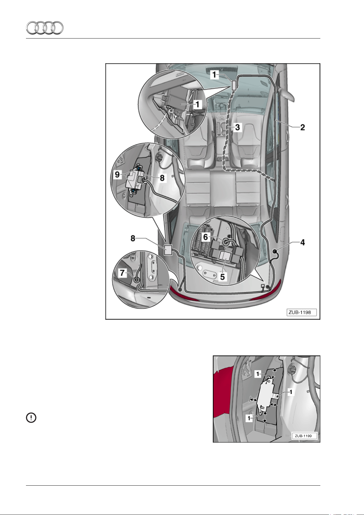
3.2 Assembly overview of the electrical connection
1 - Electrical connection
— CAN bus
2 - Retrofit wiring har-
ness — route for lefthand drive vehicles
3 - Retrofit wiring har-
ness — route for
right-hand drive vehicles
4 - Electrical connection
— earth
q 9 Nm
5 - Electrical connection
— power supply
6 - Electrical connection
— right sound activator
7 - Electrical connection
— left sound activator
8 - Control unit, sound
AGA
9 - Nut
q 9 Nm
3.3 Mounting the control unit — connecting to the on-board supply
– Centre the control unit holder on the insulation matting and
mark the drill points -1-.
– Punch mark the drill points.
– Drill the holes using a 3.0 mm drill bit (angle drill, cordless
screwdriver). Make sure that the clearance to wires and the
vehicle body is sufficient.
Caution
Do not drill into any wires!
For reasons associated with corrosion protection, use a
vacuum to continually collect the drilling chips while drilling. Corrosion damage due to drilling chips is not covered
by the vehicle's warranty.
4
3 Sequence of operations
Page 7

Installation instructions - Audi A4/A5 (B8 series) 2008 ▶
– Drill out the holes to 5.0 mm.
– Deburr the holes thoroughly.
– Carefully remove all chips from drilling, e.g. using a work-
shop vacuum cleaner
– In order to provide adequate protection against corrosion,
apply the following products with a brush.
◆ Single-component primer filler/surfacer LGF.008.001.42/A3
◆ Two-component vario filler/surfacer, grey LGF.786.004.A3
◆ Audi paint to match the vehicle's colour
◆ Body cavity preserving agent D.330.KD2.A1
– Position and rivet the control unit holder on the insulation
matting.
– Insert the control unit on the retrofit wiring harness, making
sure it engages.
– Screw the control unit to the holder.
– Lay the retrofit wiring harness along the standard wiring har-
ness to the relay and fuse carrier F -SF-. If the appropriate
equipment is in place, use the cable ties with clip provided to
secure the retrofit wiring harness to the rear panel.
.
Edition 1
1/2012
– Lay the connector for the actuators to the corresponding
wire grommets -arrow- .
Note
The clearance for the actuators is created by mounting the actuators ⇒ “Assembling the exhaust system: 4-cylinder
page 9 and/or ⇒ “Assembling the exhaust system: 6-cylinder
TDI” on page 13.
TDI” on
3 Sequence of operations
5
Page 8

Installation instructions - Audi A4/A5 (B8 series) 2008 ▶
Edition 11/2012
– Loosen the fuse carrier F -SF- and unclip the fuse carrier -
E-.
– Unpin the lilac/white wire and pin it into the connector hous-
ing 1J0.972.751 provided.
– Pin the open wire end lilac/white into the vacated slot in re-
lay carrier -E-.
– Connect the two free connectors, making sure they engage.
● Up to and including model year 2011:
– Unclip fuse carrier ST4.
– Unpin the wire from the fused outgoing circuit in chamber 3
– Pin the purple/white wire from the AGA wiring harness into
the vacated chamber
– Pin the unpinned wire from the vehicle wiring harness into
the connector housing provided (1J0.972.751).
– Pin the unpinned wire from the vehicle wiring harness into
the connector housing provided (1J0.972.751) and connect
to the connector (1J0.972.762) from the AGA wiring harness.
– Check for secure engagement.
– If there is no fuse in slot 3:
– Pin the purple/white wire from the AGA wiring harness into
the empty slot for fuse 3 (fuse carrier ST4).
– Insert fuse 15A (N.017.131.12) into slot 3.
– Screw the earth wire onto the earth point on the right-hand
side of the luggage compartment.
6
3 Sequence of operations
Page 9

Installation instructions - Audi A4/A5 (B8 series) 2008 ▶
Left-hand drive vehicles
– Lay the retrofit wiring harness on the standard wiring har-
ness along the right sill and glove compartment to the data
bus diagnostic interface
Right-hand drive vehicles
– Lay the retrofit wiring harness on the standard wiring har-
ness along the rear bench seat and centre console to the
data bus diagnostic interface -J533- -A-.
All vehicles
– Disconnect the connector -A2-.
– Open the plug.
– Unpin the orange/brown wire (slot 6) and pin into slot 2 with
the connector provided 4B0.972.623.
– Pin the orange/brown wire of the retrofit wiring harness into
the vacated slot.
– Unpin the orange/black wire (slot 16) and pin into slot 1 with
the connector provided 4B0.972.623.
– Pin the orange/black wire of the retrofit wiring harness into
the vacated slot.
– Connect the two free connectors, making sure they engage.
-J533- -A-.
Edition 1
1/2012
– Secure the retrofit wiring harness to protect against noise
and abrasion.
Note
◆ The assembly should be carried out after the assembled ex-
haust system is “sound-tested”.
◆ The control unit must not be coded.
3 Sequence of operations
7
Page 10

Installation instructions - Audi A4/A5 (B8 series) 2008 ▶
Edition 11/2012
3.4 Assembly overview of the 4-cylinder TDI exhaust system
1 - Mounting
2 - Clamping sleeve
q Install so that it is
free from tension
before tightening
the exhaust system
⇒ Rep. gr. 26
3 - Nut
23 Nm
q
4 - Screw
replace
q
20 Nm
q
5 - Nut
replace
q
20 Nm
q
6 - Mounting
7 - Actuator
8 - Exhaust tip
2x
q
position according
q
to the body version
concerned
9 - Pop rivet
6x
q
10 - Nut
11 - Shield
select according to
q
the body version
concerned⇒ “Parts
overview” on page 2
retrofit on the right side of the vehicle
q
Actuator
12 -
Silencer
13 -
replace
q
8
3 Sequence of operations
Page 11

Installation instructions - Audi A4/A5 (B8 series) 2008 ▶
3.5 Assembling the exhaust system: 4-cylinder TDI
– Detach the pipe clip -1-, and support the flex pipe -2-; secure
if necessary
Caution
Risk of damage to the decoupler.
◆ Do not bend the decoupler more than 10°
◆ Do not place any strain on the decoupler
◆ Do not damage the wire mesh on the decoupler
– Unscrew the exhaust pipe holder and remove the rear part
of the exhaust system.
– Dispose of pipe clip -1-.
Removing the Cw trim -3-:
– Unscrew nuts -1-, remove clip -2- and remove and discard
the Cw trim -3-.
.
Edition 1
1/2012
Removing the shield plate -2-:
– Unscrew nuts -1- and remove shield plate -2- from the left
side of the vehicle -2-.
– Remove and discard the grommets -arrow- on the left and
right side of the vehicle.
– Guide the advanced wires of the retrofit wiring harness from
the vehicle interior through the holes and insert wire grommets.
3 Sequence of operations
9
Page 12

Installation instructions - Audi A4/A5 (B8 series) 2008 ▶
Edition 11/2012
– Select the right shield plate from the assembly set to match
the vehicle type ⇒ Page 2.
– Assemble the shield plate on the left and right (from the as-
sembly set), paying attention to the position of the wires below and the edge of the shield plates -arrow-.
– Remove the diffuser and install the dual diffuser ⇒ Rep. gr.
63.
On the Audi A5 Coupé and Audi A5 Cabrio only
Special tools and workshop equipment required
◆ Chain pipe cutter -VAS 6254-
– Shortening the middle silencer at right angles using the
chain pipe cutter -VAS 6254-:
X - 60 mm
Continue for all vehicles
– Position the mountings -1- on the middle silencer - 2x
Fit the new clamping sleeve such that the screw ends do not
protrude over the bottom edge of the clamping sleeve.
● The screwed connection points to the left, viewed in the direction of travel.
– Place the middle silencer in the installation position and
screw the mountings to the vehicle. Continue to support the
middle silencer
10
3 Sequence of operations
Page 13

Installation instructions - Audi A4/A5 (B8 series) 2008 ▶
Assembling the exhaust tips
– Select the punch point to match the body version and drill a
∅ 4.0-mm hole.
A - Coupé/Cabrio
B - Saloon/Avant and Sportback vehicles from model year 2012
C - Sportback vehicles from model years up to and including
1
201
– Note the installation position of the actuators and insert and
rivet the exhaust tips ⇒ Fig. “Aligning the exhaust tips” on
12
page
Assembling the actuators
– Position the mountings onto the actuators.
Edition 1
1/2012
– Place the actuators in the installation position, attach the
connectors, position and tighten the mountings -1-.
– Position the clamping sleeves -2- central to the separating
cut.
● Installation position: screw fittings forward.
– Before tightening the clamping sleeves -2-, install the ex-
haust system so that it is free from tension ⇒
⇒ Fig. on page 12.
Rep. gr. 26 and
3 Sequence of operations
11
Page 14

Installation instructions - Audi A4/A5 (B8 series) 2008 ▶
Edition 11/2012
Aligning the exhaust tips
Dimension -x- left = dimension -x- right
– Rotate the clamping sleeves so that the screw ends do not
protrude over the bottom edge of the clamping sleeve.
Tightening torques ⇒ Page 8
12
3 Sequence of operations
Page 15

Installation instructions - Audi A4/A5 (B8 series) 2008 ▶
Edition 1
3.6 Assembly overview of the 6-cylinder TDI exhaust system
1 - Y-pipe
q remains in the vehi-
cle
2 - Nut
q 23 Nm
3 - Clamping sleeve
q Install so that it is
free from tension
before tightening
the exhaust system
⇒ Rep. gr
4 - Actuator
5 - Exhaust tip
q 2x
q position according
to the body version
concerned
6 - Pop rivet
q 6 x
7 - Nut
q replace
q 20 Nm
8 - Mounting
9 - Actuator
10 - Sound exhaust sys-
tem dual nozzle
. 26
1/2012
3.7 Assembling the exhaust system: 6-cylinder TDI
Special tools and workshop equipment required
◆ Chain pipe cutter -VAS 6254-
3 Sequence of operations
13
Page 16

Installation instructions - Audi A4/A5 (B8 series) 2008 ▶
Edition 11/2012
– Separate the exhaust pipe at right-angles at the cut-off
points at the middle punch point -arrows- using the chain
pipe cutter -VAS 6254-.
– Loosen the front clamping sleeve -1- and lower the Y pipe
-3-.
– Position the dual nozzle -2- on the Y pipe -3-.
– Position the plastic or wooden part -1- on the dual nozzle
-2-.
– Hammer the dual nozzle -2- into the Y pipe -3- using the
soft-head hammer. The dual nozzle is now in the installation
position.
– Install the Y pipe.
Removing shield plates -2-:
– Unscrew nuts -1- and remove the shield plates -2- from the
left and right side of the vehicle -2-.
14
3 Sequence of operations
Page 17

Installation instructions - Audi A4/A5 (B8 series) 2008 ▶
– Remove and discard the grommets -arrow- on the left and
right side of the vehicle.
– Guide the advanced wires of the retrofit wiring harness from
the vehicle interior through the holes and insert wire grommets.
– Assemble the shield plate, at the same time being aware of
the position of the wires below and at the edge of the shield
plates -arrow-.
Edition 1
1/2012
Assembling the exhaust tips
– Select the punch point to match the body version and drill a
∅ 4.0-mm hole.
A - Coupé/Cabrio
B - Saloon/Avant and Sportback vehicles from model year 2012
C - Sportback vehicles from model years up to and including
1
201
– Note the installation position of the actuators and insert and
rivet the exhaust tips ⇒ Fig. “Aligning the exhaust tips” on
16
page
Assembling the actuators
– Position the mountings onto the actuators.
3 Sequence of operations
15
Page 18

Installation instructions - Audi A4/A5 (B8 series) 2008 ▶
Edition 11/2012
– Place the actuators in the installation position, attach the
connectors, position and tighten the mountings -1-.
– Position the clamping sleeves -2- central to the separating
cut.
● Installation position: screw fittings forward.
– Before tightening the clamping sleeves -2-, set the exhaust
system so there is no tension ⇒ Rep. gr. 26 and
⇒ Fig. “Aligning the exhaust tips” on page 16
Aligning the exhaust tips
Dimension -x- left = dimension -x- right
– Rotate the clamping sleeves so that the screw ends do not
protrude over the bottom edge of the clamping sleeve.
Tightening torques ⇒ Page 13
3.8 Final tasks
– Connect the battery -A- ⇒ Rep. gr. 27.
– Carry out a functional check.
16
3 Sequence of operations
Page 19

Installation instructions - Audi A4/A5 (B8 series) 2008 ▶
– Secure the retrofit wiring harness using the cable ties provi-
ded, to prevent noise and abrasion.
– Re-install all removed parts.
– Where necessary, paint the inside of the exhaust tips with
matt black paint.
Note
The genuine AUDI replacement exhaust system holds ECE
type approval (E24 031446). It is therefore not necessary to car
ry any additional documents with the system, or enter information in the vehicle registration certificate.
Edition 1
-
1/2012
3 Sequence of operations
17
Page 20

 Loading...