

Page 1
Audi A4 No.2/1
Wiring diagram
St andard Equipment
from 2002 m. y.
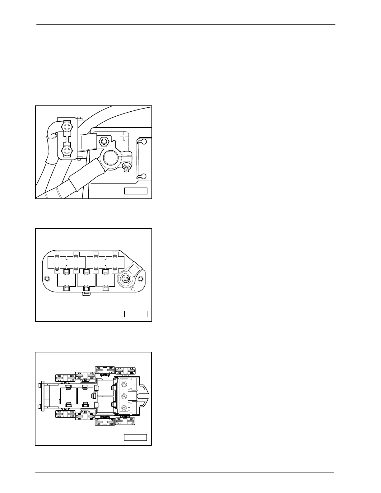
Main fuse
A97--0220
Connector station E-box,plenum cham ber
1 2 3 4
5 6 7
A97--0248
4-Pin Relay Carrier with threaded
connection
A
E
B
1
2
F
C
3
4
G
D
H
Edition 08/ 01
W42.USA.5504.01.21
A97--0245
Page 2
Audi A4 No.2/2
Wiring diagram
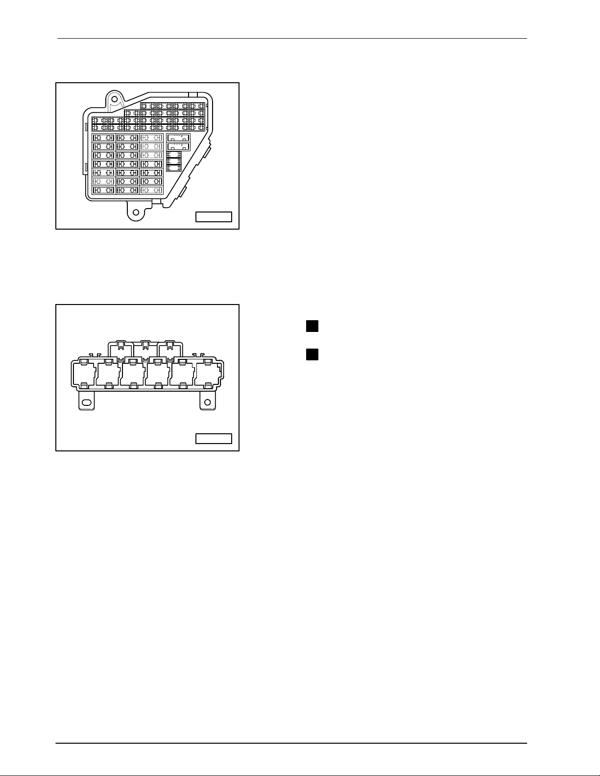
Fuseholder
Fuse Colors
30 A
-
34
12
7 6 5
36 35 34 33 32 31
37
30 29 28 27 26 25 24
15 14 13 12
11 10 9 8
39 38
44 43 42 41 40
23 22 21 20
19 18 17 16
Res
Res
Res
Res
Res
25 A
20 A
15 A
10 A
7, 5A
Fuse in fusebox from 23 onwards are numbered 223
Green
-
White
-
Yellow
-
Blue
-
Red
- Orange
5A - Beige
onwards in Current Flow Diagram.
A97--0242
9-Pin Relay Carrier in the instrument
panel
Relay Location :
A
8 97
1
2 3 4 5 6
B
A97--0243
- Horn Relay
3
- LoadReduction Relay
6
Edition 08/ 01
W42.USA.5504.01.21
Page 3
Audi A4 No.2/3
Wiring diagram
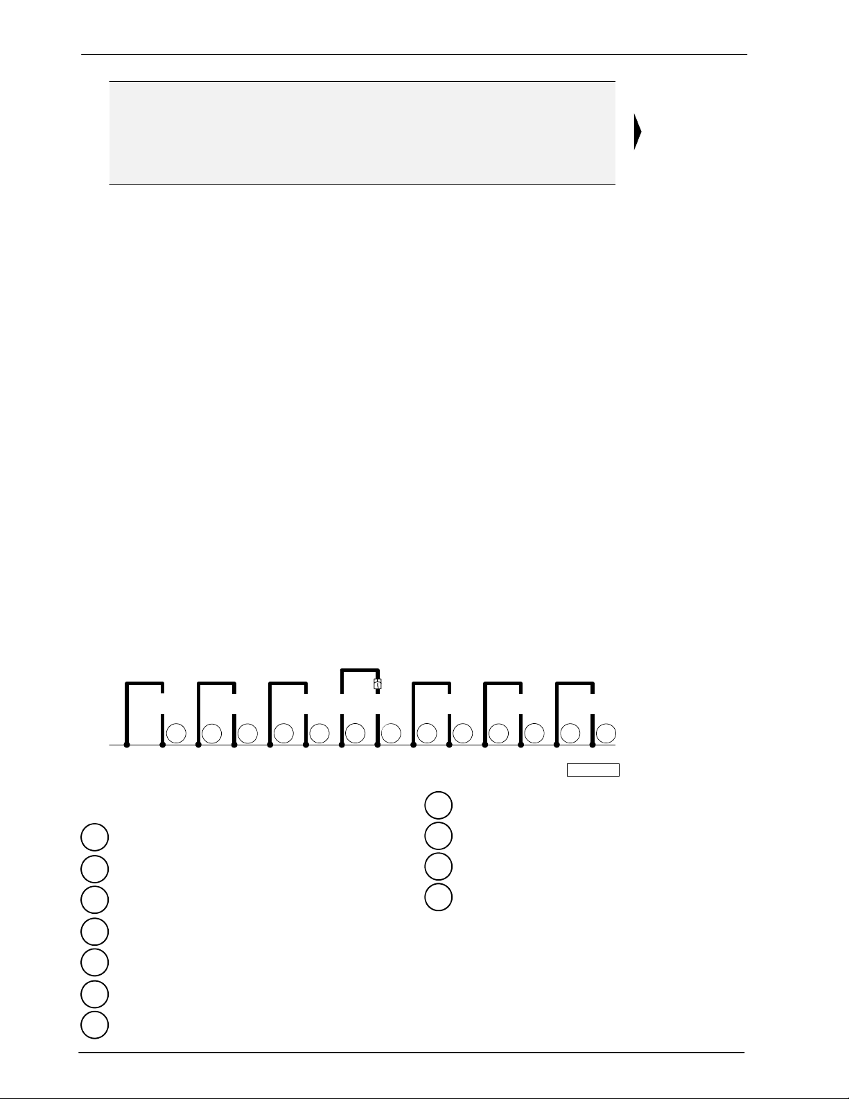
35,0
sw
3
1234567891011121314
4,0
br
8312
12 179
4,0
2,5
br
br
T4k - 4-Pin Connector, black, near front bumper
T4k/4
2,5
br
179 345
6,0
br
78 249
6,0
br
8650
179 - Ground connection, in left headlight wiring
harness
3 - Ground strap, engine to body
249 - Ground connection -2-, in wiring harness
interior
12 - Ground connection, in engine compartment,
left
44 - Ground connection (lower left A-pillar)
345 - Ground connection (in bumper wiring harness),
Fanfare/Fog light
347 - Ground connection (in roof wiring harness)
50 - Ground connection, in luggage compartment,
left
78 - Ground connection (lower right B-pillar)
83 - Ground connection -1-, in right front wiring
harness
86 - Ground connection -1-, in rear wiring harness
2,5
br
34744
97--52805
rs = pink
ws = white
sw = black
ro = red
br = brown
gn = green
bl = blue
gr = grey
li = lilac
ge = yellow
or = orange
Edition 08/ 01
W42.USA.5504.01.21
Ground connections
Page 4
Audi A4 No.2/4
Wiring diagram
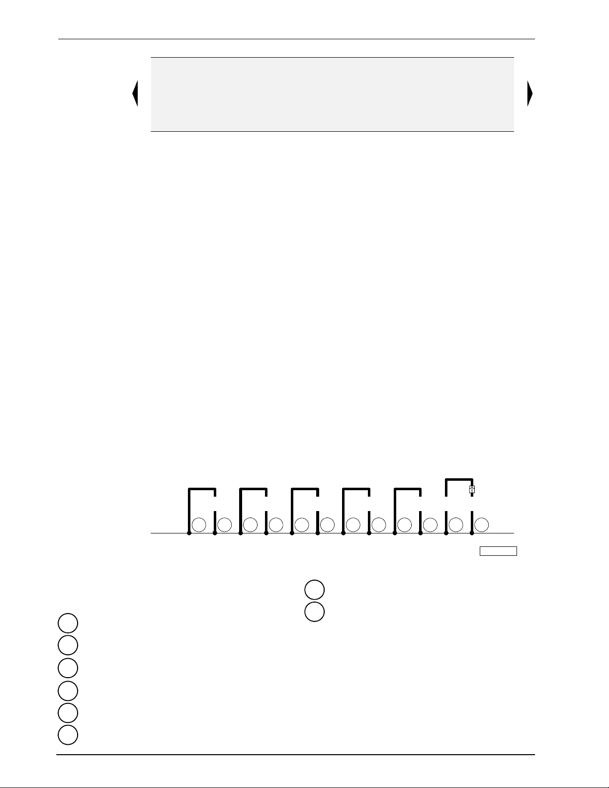
rs = pink
ws = white
sw = black
ro = red
br = brown
gn = green
bl = blue
gr = grey
li = lilac
ge = yellow
or = orange
15 16 17 18 19 20 21 22 23 24 25 26 27 28
6,0
br
32
44 81
44 238
T10c - 10-Pin Connector, violet, connector station
A-pillar,left
32 - Ground connection, behind instrument panel,
left
43 - Ground connection (lower right A-pillar)
44 - Ground connection (lower left A-pillar)
81 - Ground connection -1-, in instrument panel
wiring harness
135 - Ground connection -2-,in instrument panel
wiring harness
176 - Ground connection, in right headlight wiring
harness
Ground connections
6,0
T10c
br
6,0
br
43 135
4,0
br
43 176
6,0
1,5
br
br
43 261135
1,5
br
/1
97--53043
238 - Ground connection -1-, in wiring harness
interior
261 - Ground connection, in wiring harness heated
spray jet
Edition 08/ 01
W42.USA.5504.01.21
Page 5
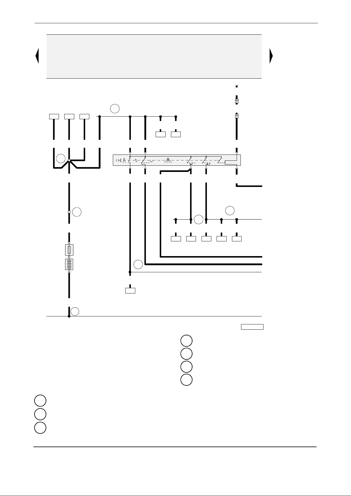
Audi A4 No.2/5
Wiring diagram
B
2,5
sw
T1
2,5
ro/sw
2,5
ro/sw
0,35
bl
T10a/4
5/50b
D
1/50
a
163 190
6,0
6,0
ro
ro
501
16,0
ro
208
6,0
ro
6,0
A32
2,5ro2,5
ro
81 82
2,5
2,5
ro
ro
01 0123
3/30 7/30
0,5
0,35
ro
gr/ge
ro
2/754/P8/86s
6/15
0,5
ge/sw
ge/sw
1,0
4,0
sw
500
A33
1,0
16,0
ro
S88
150A
+
0,22
ro
221
A21
A
--
35,0
br
11
29 30 31 32 33 34 35 36 37 38 39 40 41 42
A-Battery
0,22
ge/sw
ge/sw
141
A2 - Plus connection (15), in instrument panel wiring
B-Starter
D - Ignition/Starter Sw itch
A21 - Wire connect ion (86s), in instrument panel
S88 - Fuse Strip (main fuse)
T1 - 1-Pin Connector, black, engine compartment,
A32 - Plus connection (30), in instrument panel wiring
right
T10a - 10-Pin Connector, brown, connector station
A33 - Wire connect i on (75), in instrument panel
E-box, plenum chamber
4,0
sw
199
203
harness
wiring harness
harness
wiring harness
0,35
sw
227
A2
0,35
sw
92
97--54123
b
c
d
e
rs = pink
ws = white
sw = black
ro = red
br = brown
gn = green
bl = blue
gr = grey
li = lilac
ge = yellow
or = orange
11 - Ground connection, in battery box
500 - Threaded connection -1-(30), on the relay plate
501 - Threaded connection -2-(30), on the relay plate
Edition 12/ 01
W42.USA.5504.02.21
Ignition/ Starter Swit ch,m ain fuse
Page 6
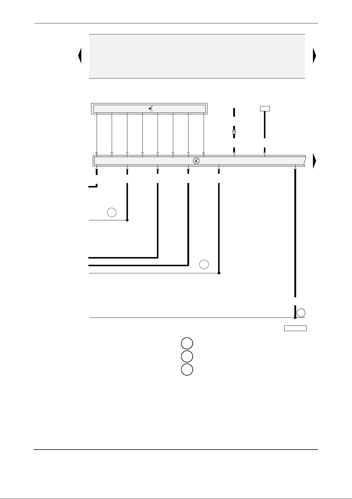
Audi A4 No.2/6
Wiring diagram
rs = pink
ws = white
sw = black
ro = red
br = brown
gn = green
bl = blue
gr = grey
li = lilac
ge = yellow
or = orange
J...
E45
0,35
bl/gn
T17e/10
0,22
bl/gn
T16a/5
T16a/15
0,35
bl
a
A2
b
c
d
e
43 44 45 46 47 48 49 50 51 52 53 54
T16a/13
0,5
sw
T16a/12 T16a/16 T16a/1
0,5
ge/sw
0,35
gr/ge
A21
T16a/14
0,22
ro
170
1,0
ro/ge
T16a/2
55 56
97--53371
J 527
1,0
br
135
E45 - Cruise Control Switch
J... - Engine Control Module (ECM)
J527 - Steering Column Electronic Systems Control
Module
T16a - 16-PinConnector, black, on steering Column
Electronic Systems Control Module
135 - Ground connection -2-,in instrument panel
wiring harness
A2 - Plus connection (15), in instrument panel wiring
harness
A21 - Wire connect ion (86s), in instrument panel
wiring harness
T17e - 17-Pin Connector, white, connector st ation
E-box, plenum chamber
Steering Column Elect ronic Systems Cont rol M odule, Cruise Cont rol
Edition 12/ 01
W42.USA.5504.02.21
Page 7
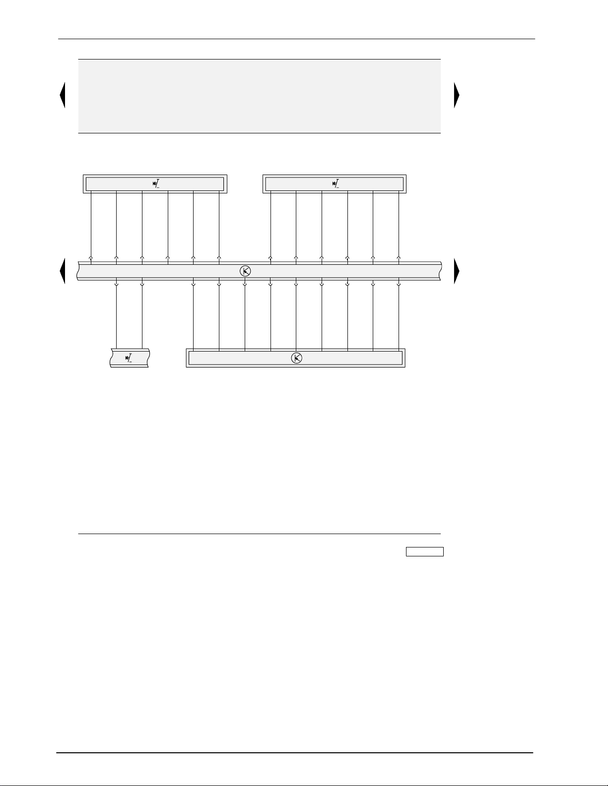
Audi A4 No.2/7
Wiring diagram
E2 E22
J 527
57 58 59 60 61 62 63 64 65 66 67 68
E2 - Turn signal switch
E22 - Windshield Wiper/Washer Switch
G85 - Steering Angle Sensor
H - Signal horn activation
J527 - Steering Column Electronic Systems Control
Module
G85H
rs = pink
ws = white
sw = black
ro = red
br = brown
gn = green
bl = blue
gr = grey
li = lilac
ge = yellow
or = orange
69 70
97--52809
Edition 08/ 01
W42.USA.5504.01.21
Turn signal sw itch,w indshield Wiper/ Washer Sw it ch,steering Angle Sensor,
signal horn activation, steering Column ElectronicSystem s Cont rol Module
Page 8

Audi A4 No.2/8
0,22
0,22
or/gn
T16a/9
0,22
or/br
187 188
or/br
T16a/8
Wiring diagram
0,22
0,22
or/gn
or/gn
T32b/13
0,35
gn/li
T32b
/11
0,22
or/br
2,5
gn/ge
T32b/12
T10b/3
sw/ws
T10b/4
2,5
A
146
T23/1 T23/2
0,5
sw/li
36
37
2,5
2,5
ro
A
147
0,5
bl/li
ro/ws
T10b/9
T10b/2
1,5
ro
T10b/10
T10b/7
J
519
T23/20
rs = pink
ws = white
sw = black
ro = red
br = brown
gn = green
bl = blue
gr = grey
li = lilac
ge = yellow
or = orange
0,22
or/br
230232
J 527
T16a/11
T10c
T10c/4T10c
/2
0,35
1,5
gn/li
gn/ge
3/53e 1/53b 2/53
1,5
sw/ws
M
1,5
br
4/31
261
/8
0,5
sw/li
M
T17
T17
/8
/7
0,5
1,5
br
ro/ws
1
V5V
2 1
2,5
T1a
2
M
V11
1,0
br
44
br
135
T16a/10
0,22
or/sw
71 72 73 74 75 76 77 78 79 80 81 82 83 84
0,35
br
135
97--53372
J519 - Vehicle Electrical System Control Module
J527 - Steering Column Electronic Systems Control
Module
V - Windshield Wiper Mot or
V5 - Windshield Washer Pump
V11 - Headlight Washer Pump
T1a - 1-Pin Connector, black, connector station
A-pillar,left
44 - Ground connection (lower left A-pillar)
T10b - 10-Pin Connector, black, on vehicle Electrical
System Control Module
T10c - 10-Pin Connector, violet, connector station
A-pillar,left
T16a - 16-PinConnector, black, on steering Column
Electronic Systems Control Module
T17 - 17-Pin Connector, black, connector station
A-pillar,left
T23 - 23-Pin Connector, black, on vehicle Electrical
135 - Ground connection -2-,in instrument panel
wiring harness
261 - Ground connection, in wiring harness heated
spray jet
A146 - Comfort System High-busConnection (in
instrum ent panel wiring harness)
A147 - Comfort System Low-bus Connection (in
instrum ent panel wiring harness)
System Control Module
T32b - 32-Pin Connector, grey, on vehicle Electrical
System Control Module
Vehicle Elect rical System Control M odule,steering Column Electronic
SystemsControl Module,w indshield Wiper M otor,Washer Pump
Edition 08/ 01
W42.USA.5504.01.21
Page 9

Audi A4 No.2/9
T32b
/28
T32b
/29
T32b
/32
/26
0,35
gr
T32b/25
Wiring diagram
16441163 245
519
J
T32b/27T32b
A3
0,22
0,35
0,35
0,35
ws/gn
ge
li
bl
0,5ro0,35
15/30
102A
14/58 10/317/A 8/NL3/TFL
0,35
ge
11/56
0,35
gr
sw
23E
0,5
sw/ge
2/XR
0,35
gr/ws
9/NSL
0,5
gr/bl
17/58d1/XZ
1
E
A51
243241 102 123
0,22
*
gr/bl
1/58S
85 86 87 88 89 90 91 92 93 94 95 96 97 98
0,22
*
gr/bl
8/58S 2/56b
5/31
3/G
0,5
gr/ge
0,22
br
238
E1 - Light switch
E23 - Fog Light Switch
E102 - Headlight Adjuster
J519 - Vehicle Electrical System Control Module
T32b - 32-Pin Connector, grey, on vehicle Electrical
System Control Module
0,22
ge
A114
*
*
*
E
102
0,35
0,35
gr/ge
gr/ge
135 - Ground connection -2-,in instrument panel
wiring harness
238 - Ground connection -1-, in wiring harness
interior
A3 - Plus connection (58), in instrument panel wiring
harness
A51 - Wire connect i on (56), in instrument panel
wiring harness
A114 - Wire connection (headlight Adjuster), in
instrum ent panel wiring harness
0,5
br
135
97--53373
rs = pink
ws = white
sw = black
ro = red
br = brown
gn = green
bl = blue
gr = grey
li = lilac
ge = yellow
or = orange
Edition 08/ 01
W42.USA.5504.01.21
* - Not applicable to USA/CDN
Light swit ch,headlight adjuster, VehicleElectrical System Control Module
Page 10

Audi A4 No.2/10
Wiring diagram
519
J
rs = pink
ws = white
sw = black
ro = red
br = brown
gn = green
bl = blue
gr = grey
li = lilac
ge = yellow
or = orange
T23
/21
0,5
ws/gn
94
0,5
gn/ge
T17/16
1,0
ws/gn
V48
*
0,35
gn/ge
6/G
*
0,5
ge/sw
0,5
br
T4k/1
1,0
ws/gn
1
L 22
2
1,0
br
345
100 101 102 103 104 105 106 107 108 109 110 111
99
4/31
179
1,0
ge/sw
1,5
ge/sw
T23/23
T17a
/16
5/56b2/56b
L1
1,0
ws/sw
1,0
ws/sw
1,0
ws/sw
1,0
br
E117
10/31
179
0,5
gr/sw
0,5
gr/sw
T32b/3T23/18
0,5
sw/bl
0,5
sw/bl
0,5
sw/bl
2,5
br
T23/9
A6
9/BL7/58L1/56a
M5M1
8/31
179
0,5
sw/gn
0,5
sw/gn
0,5
gn
0,5
br
T32b/21
A181
T17a/3T17a/2T17a/1T17a/15T17a/8
+
M18
--
179
112
97--53374
J519 - Vehicle Electrical System Control Module
L1 - Twin filament bulb for headlight, left
L22 - Left Front Fog Light
M1 - Left Parking Light
M5 - Left Front Turn Signal Light
M18 - Left Side Turn Signal Light
T4k - 4-Pin Connector, black, near front bumper
T17 - 17-Pin Connector, black, connector station
A-pillar,left
T17a - 17-Pin Connector, red, connector station
A-pillar,left
T23 - 23-Pin Connector, black, on vehicle Electrical
System Control Module
T32b - 32-Pin Connector, grey, on vehicle Electrical
System Control Module
V48 - Left Headlight Beam Adjusting Motor*
Left headlight, left Fog Light
179 - Ground connection, in left headlight wiring
harness
345 - Ground connection (in bumper wiring harness),
Fanfare/Fog light
A6 - Plus connection (left turn signal), in instrument
panel wiring harness
A181 - Left Turn Signal Plus Connection -2-(in
instrum ent panel wiring harness)
E117 - Connector (56a left), in instrument panel wiring
harness
* - Not applicable to USA/CDN
Edition 08/ 01
W42.USA.5504.01.21
Page 11

Audi A4 No.2/11
Wiring diagram
J 519
T32b/22 T32b/5 T23/16
0,5
bl/sw
A180
0,5
bl/sw
T17c/3 T17c/2 T17c/1 T17c
0,5
gn/sw
0,5
gn/sw
T23/7
A5
0,5
gr/ro
0,5
gr/ro
A85
1,0
ws/ge
1,0
ws/ge
E116
/15
1,0
ge/ws
1,5
ge/ws
T23/22
T17c/16
T23/19
0,5
ws/bl
95
0,5
gr/ge
T17c/8
*
*
1,0
ws/bl
T17/15
T4k/2
0,5
gn
+
M
19
--
0,5
br
176 176
113 114 115 116 117 118 119 120 121 122 123 124 125 126
0,5
sw/gr
9/BR 7/58R
0,5
gr/ro
M7 M3 L2
10/31
1,0
br
176
1,5
1,5
ws/ge
ge/ws
1/56a 5/56b 2/56b 6/G
8/31
2,5
br
0,5
ge/ws
0,5
br
4/31
176
0,35
gr/ge
V49
1,0
ws/bl
1
L 23
1,0
2
br
345
97--53375
*
rs = pink
ws = white
sw = black
ro = red
br = brown
gn = green
bl = blue
gr = grey
li = lilac
ge = yellow
or = orange
J519 - Vehicle Electrical System Control Module
L2 - Twin filament bulb for headlight, right
L23 - Right Front Fog Light
M3 - Right Parking Light
M7 - Right Front Turn Signal Light
M19 - Right Side Turn Signal Light
T4k - 4-Pin Connector, black, near front bumper
T17 - 17-Pin Connector, black, connector station
A-pillar,left
T17c - 17-Pin Connector, red, connector station
A-pillar,right
T23 - 23-Pin Connector, black, on vehicle Electrical
System Control Module
T32b - 32-Pin Connector, grey, on vehicle Electrical
System Control Module
V49 - Right Headlight Beam Adjusting Motor*
Edition 08/ 01
W42.USA.5504.01.21
176 - Ground connection, in right headlight wiring
harness
345 - Ground connection (in bumper wiring harness),
Fanfare/Fog light
A5 - Plusconnection (right turn signal),in instrument
panel wiring harness
A85 - Wire connect ion (58R), in instrument panel
wiring harness
A180 - Right Turn Signal Plus Connection -2-(in
instrum ent panel wiring harness)
E116 - Connector (56a, right), in instrument panel
wiring harness
* - Not applicable to USA/CDN
Right headlight, right Fog Light
Page 12

Audi A4 No.2/12
Wiring diagram
519
J
rs = pink
ws = white
sw = black
ro = red
T23/15
T23/5
1,0
0,5
gr/ws
0,5
gn/bl
0,5
gn/bl
bl/ro
3/RF 5/BL 4/58L
M16 L46 M6 M9
T32b
T23/6
/4
0,5
0,35
ro/sw
gr/sw
B
186
M4 M2M4 M2
br = brown
gn = green
bl = blue
gr = grey
li = lilac
ge = yellow
or = orange
127 128 129 130 131 132 133 134 135 136 137 138 139 140
J519 - Vehicle Electrical System Control Module
L46 - Left Rear Fog Light
M2 - Right Tail Light
M4 - Left Tail Light
M6 - Left Rear Turn Signal Light
M8 - Right Rear Turn Signal Light
M9 - Left Brake Light
M10 - Right Brake Light
M16 - Left Back-Up Light
M17 - Right Back-Up Light
M25 - High-mount Brake Light
T4l - 4-Pin Connector, black, in rear lid
T23 - 23-Pin Connector, black, on vehicle Electrical
System Control Module
T32b - 32-Pin Connector, grey, on vehicle Electrical
System Control Module
X - License Plate Light
Rear lights
T23/12
6/54L
1/31
1,5
br
0,35
sw/ro
T23/14
1/54
M25
2/31
T23/10
T32b
T23/4
/7
0,5
0,35
gr/ro
0,5
sw/gn
B
187
0,5
sw/gn
M8 M17
ro/sw
2/54R 4/58R 1/BR2/NSL 3/RF
M10
5/31
**
1,0
bl/ro
T23/8
0,35
gr
0,35
gr
0,35
ro
0,35
bl
T32b/6
B
132
T4l/3
1
X
2
T4l/4
0,35
br
86
86
1,5
br
249
0,35
br
86
97--53376
86 - Ground connection -1-, in rear wiring harness
249 - Ground connection -2-, in wiring harness
interior
B132 - Connector (license plate light), in wiring
harness interior
B186 - Connector -2-(BL), in wiring harness interior
B187 - Connector -2-(BR), in wiring harness interior
* - M2/M4 tw in filament bulb (5W), not required
Edition 08/ 01
W42.USA.5504.01.21
Page 13

Audi A4 No.2/13
T32b
0,22
ge/sw
37
E229
T32b
/17
0,22
ge/bl
1 62
T32b
/8
0,22
ro/ge
0,22
ro/ge
/9
B260
43
0,22
ws/li
0,22
ws/li
/18
T17f
/13
2
0,22
ge/ro
0,22
ge/ro
G213
T32b/19T32b
T17f
/14
31
Wiring diagram
176
1,5
2,5
ro/ge
ro/ge
2,5
sw/ws
2,5
sw/ws
2/30
8/87
gn/ge
E112
E112
T17a/17
0,35
4/85
6/86
4
J
3
0,35
gn/ge
T32b/1
A90
2,5
sw/ws
2,5
sw/ws
1,5
sw/ws
1,5
br
2,5
br
T4k/3
H2
519
J
1,5
sw/ws
1,5
br
X66
H7
345
0,22
0,22
br
135
141 142 143 144 145 146 147 148 149 150 151 152 153 154
E229- Swit ch for emergency flasher
0,22
br
br
135
347
135 - Ground connection -2-,in instrument panel
G213- Rain Sensor
H2 - High Tone Horn
179 - Ground connection, in left headlight wiring
H7 - Low Tone Horn
J4 - Horn Relay
345 - Ground connection (in bumper wiring harness),
J519 - Vehicle Electrical System Control Module
T4k - 4-Pin Connector, black, near front bumper
347 - Ground connection (in roof wiring harness)
2,5
br
wiring harness
harness
Fanfare/Fog light
T17a - 17-Pin Connector, red, connector station
A-pillar,left
T17f - 17-Pin Connector, orange, connector station
A-pillar,left
T32b - 32-Pin Connector, grey, on vehicle Electrical
System Control Module
A90 - Connector (t wo-tone horn), in instrument panel
wiring harness
B260 - Connector (emergency flasher), in wiring
harness interior
E112 - Connector (Horn-87h)in instrument panel
wiring harness
X66 - Horn Connection (in front bumper wiring
harness)
T4k/4
179
rs = pink
ws = white
sw = black
ro = red
br = brown
gn = green
bl = blue
gr = grey
li = lilac
ge = yellow
or = orange
97--53377
Edition 08/ 01
W42.USA.5504.01.21
Swit ch for emergencyflasher, t wo-tone horn,rain Sensor,
vehicleElectrical System Cont rol Module
Page 14

Audi A4 No.2/14
T32b
T32b
/10
/15
Wiring diagram
519
J
T10b/8 T10b/5
T32b/2
6,0
29
ro
0,5
ro
91
A57
a
A34
rs = pink
ws = white
sw = black
ro = red
br = brown
gn = green
bl = blue
gr = grey
li = lilac
ge = yellow
or = orange
0,22
0,22
ro/sw
ws/ro
A154
1,0
1,0
ro/sw
ws/ro
24
A18
0,5
sw/ge
0,5ro4,0
ro
31
4
2
4,0
sw/ge
0,5
sw/ge
59
J
6
94
4,0
sw/ge
2,5
sw/ge
S
30A
sw/ge
236
sw/gn
F
13
1,0
sw/br
204
1,0
ro/br
*
97--53378
0,5
*
ro/ws
*
A104
0,5
ro/ws
T10a/8
155 156 157 158 159 160 161 162 163 164 165 166 167 168
2,5
2,5
3736
S
20A
37a36a
237
b
F - Brake Light Switch
J59 - Load Reduction Relay
J519 - Vehicle Electrical System Control Module
S236- Fuse in f use holder
S237- Fuse in f use holder
T10a - 10-Pin Connector, brown, connector station
E-box, plenum chamber
T10b - 10-Pin Connector, black, on vehicle Electrical
System Control Module
T32b - 32-Pin Connector, grey, on vehicle Electrical
A18 - Wire connection (54), in instrument panel
wiring harness
A34 - Wire connect ion (75x), in instrument panel
wiring harness
A57 - Plus connection -3-(30), in instrument panel
wiring harness
A154 - Wire connection (Brake Light Switch), in
instrum ent panel wiring harness
A104 - Plus connector -2-, in instrument panel wiring
harness
System Control Module
Brake Light Swit ch,load Reduction Relay,vehicle Elect rical System
Control Module
Edition 08/ 01
W42.USA.5504.01.21
Page 15

Audi A4 No.2/15
Wiring diagram
A57
a
6,0
ro
12 39 40 3313 14 15
12
S
10AS10AS10A
10A
12a 39a 40a 33a13a 14a 15a
0,5
1,0
ro/sw
ro/ge
54 225 147
260
b
13 14 15
1,0
ro/br
1,0
ro/bl
S
A50
0,5
ro/bl
0,35
gr
A129
2,5
ro/bl
2,5
ro/bl
S
20A
A46
239
2,5
ro/ge
S
25A
240
2,5
ro
1,5
ro/bl
S
15A
2
233
249
0,35
gr/bl
T8/7 T8/8T8/2
3
1,5
1,5
br
br
135
610
169 170 171 172 173 174 175 176 177 178 179 180
1,5
ro
22
251
0,22
1
L
28
U1
gr/bl
1
rs = pink
L15
2
ws = white
sw = black
ro = red
br = brown
gn = green
bl = blue
0,22
br
238
181 182
97--53379
gr = grey
li = lilac
ge = yellow
or = orange
L15 - Ashtray Light
L28 - Cigarette Lighter Light
S12 - Fuse in fuse holder/relay panel
S13 - Fuse in fuse holder/relay panel
S14 - Fuse in fuse holder/relay panel
S15 - Fuse in fuse holder/relay panel
S233- Fuse in f use holder
S239- Fuse in f use holder
S240- Fuse in f use holder
T8 - 8-Pin Connector, black,radio connector III
U1 - Cigarett e Lighter
Edition 12/ 01
W42.USA.5504.02.21
135 - Ground connection -2-,in instrument panel
wiring harness
238 - Ground connection -1-, in wiring harness
interior
610 - Ground connection (Audio)(under center
console, front)
A46 - Plus connection (30-from radio), in instrument
panel wiring harness
A50 - Plus connection (30as), in instrument panel
wiring harness
A57 - Plus connection -3-(30), in instrument panel
wiring harness
A129 - Wire connection (quiet switch), in instrument
panel wiring harness
Ashtray Light, cigarette Lighter, fuses, radio connector III
Page 16

Audi A4 No.2/16
87
A
Wiring diagram
0,22
0,22
1,0
bl/ro
or/gn
or/gn
30
6,0
ro
26
0,5
ro/li
2
S
5A
2
4,0
ws/ge
S
30A
26a2a
226
24
7473
V/12III/7
/4
1,0
bl/ro
2
W6
1
0,5
br/gr
17d
T
/15
2
0,5
ro/ge
0,5
ro/ge
rs = pink
ws = white
sw = black
ro = red
br = brown
gn = green
bl = blue
gr = grey
li = lilac
ge = yellow
or = orange
1,0
bl/ro
206
183 184 185 186 187 188 189 190 191 192 193 194
0,5
0,5
br
br
E
1
T12d/7
238
26
C18 - Wi ndshield Ant enna Suppression Filter
E26 - Glove c ompartment light
E87 - A/C Control Head
J393 - Central control module for comf ort system
S2 - Fuse in fuse holder/relay panel
S226- Fuse in f use holder
T12d - 12-Pin Connector, brown, near glove
Compartment
T17d - 17-Pin Connector, red, connector station E-box,
plenum chamber
W6 - Glove Compartment Light
W9 - Left Footwell Light
W10 - Right Footwell Light
Z1 - Heated rear window
F/5
C
18
87E
F/6
4,0
ws/li
B180
4,0
ws/li
2
W
1
B248
9W10
C
18
73
195 196
0,35
ro/gr
V/13
II/13II/6I/4
T12d/2T12d
A29
J
393
0,5
ro/li
0,35
ro/li
T12d/1
0,5
ro/li
1
2
0,5
ro/gr
0,35
ro/gn
73 - Ground connection, on roof bow, rear
238 - Ground connection -1-, in wiring harness
interior
A29 - Wire connect ion (interior light), in instrument
panel wiring harness
A87 - Connector (reverse lamp), in instrument panel
wiring harness
B180 - Connection (heated rear window), in wiring
harness interior
B248 - Heated Rear Window Connection -2- (ininterior
wiring harness)
Z
C
4,0
br
73
97--54468
1
18
Glove Compartment Light, left Foot well Light, right Footwell Light,
heated rear window
Edition 12/ 01
W42.USA.5504.02.21
Page 17

Audi A4 No. 2/ 17
Wiring diagram
6,0
31
ro
38
1,0
ge/sw
0,5
gr/gn
*
3
3
S
5A
3a
*
39
4,0
sw
1,0
sw/ro
5
S
10A
5a
A74
5
1,5
sw/br
7
S
10A
7a
A20
7
1,5
sw/bl
31
S
15A
31a
231
T10c/3
1,0
0,5
sw/bl
sw/bl
1,5
sw/bl
1,0
bl/ro
183
249 - Ground connection -2-, in wiring harness
1,0
sw/ro
sw/br
0,5
gr/gn
*
1
20Z
2
0,5
br
*
261 261
197 198 199 200 201 202 203 204 205 206 207 208
0,5
gr/gn
0,5
br
*
1
21Z
2
223 156 258
*
F4 - Back-UpLight Switch
1,5
S3 - Fuse in fuse holder/relay panel
S5 - Fuse in fuse holder/relay panel
261 - Ground connection, in wiring harness heated
S7 - Fuse in fuse holder/relay panel
S231- Fuse in f use holder
A20 - Wire connect ion (15a),in instrument panel
S235- Fuse in f use holder
T10a - 10-Pin Connector, brown, connector station
A52 - Plus connection -2-(30), in instrument panel
E-box, plenum chamber
T10c - 10-Pin Connector, violet, connector station
A70 - Connector (15a, fuse 231), in instrument panel
A-pillar,left
U-Socket
A74 - Connector (15a, fuse 5), in instrument panel
Z20 - Left Washer Nozzle Heater
Z21 - Right Washer Nozzle Heater
3 - Only heated spray jets
A70
T10a/5
3
F4
2
interior
spray jet
wiring harness
wiring harness
wiring harness
wiring harness
2,5
ro
2,5
ro/gr
2,5
br
2
1
249
A52
35
S
30A
35a
235
U
rs = pink
ws = white
sw = black
ro = red
br = brown
gn = green
bl = blue
gr = grey
li = lilac
ge = yellow
or = orange
209 210
97--54469
Edition 12/ 01
W42.USA.5504.02.21
Fuses, Socket, heated spray jet
Page 18

Audi A4 No. 2/18
Wiring diagram
34
0,22
ro
T32/22
0,22
0,22
sw
gn
T32/30 T32/31
D2
12
rs = pink
ws = white
sw = black
ro = red
br = brown
gn = green
bl = blue
gr = grey
li = lilac
ge = yellow
or = orange
0,22
br/ro
0,5
br/ro
0,35
br/ge
0,35
br/ge
T32/1
T17/9
F
T17
/10
269
77
0,35
bl/ge
0,5
bl/ge
0,35
br/ge
212 213 214 215 216 217 218 219 220 221 222 223 224211
T32/2
T10/7
1
3
F
66
0,35
bl/br
0,35
bl/br
0,35
br/ge
327
T32/4
T10/9
2
G
2
G3
T32/3
0,35
li/sw
2
2
0,35
br/ge
0,35
br/ge
T10
269
3
/6
0,5
br/ge
G1
T32/11
0,35
li/sw
*
2
GG169
3
0,5
*
br/ge
269
269
J
285
0,35
ge/gr
0,35
ge/gr
T32/21
T10d
/9
0,35
ro/gr
T32/23
T10a
/9
203
1,0
sw/ro
T14/4
0,35
0,35
ge/gr
2
*
0,35
br/ge
1
T14/3
F38
0,35
br/ge
0,35
br/ge
T10d
/10
269
ro/gr
G266
0,5
sw/ro
3
0,5
br
T10a
/2
1
2
83
97--54137
0,22
br/ge
T32/32
269
D2 - Induction Coil of Anti-t heft Immobilizer
T10d - 10-Pin Connector, grey, connector station
F38 - Ambient Temperature Switch
F66 - EngineCoolant Level (ECL)Warning Switch
T14 - 14-Pin Connector,black, in engine
F77 - Windshield Washer Fluid Level Warning Switch
G - Sender for f uel gauge
T17 - 17-Pin Connector, black, connector station
G1 - Fuel Gauge
G2 - Engine Coolant Temperature (ECT)Sensor
T32 - 32-Pin Connector, blue, on instrument panel
G3 - Engine Coolant Temperature (ECT)Gauge
G169- Fuel Level Sensor2
G266- Oil Level Thermal Sensor
J285 - Cont rol module with indicator unit in instrument
panel insert
T10 - 10-Pin Connector, black, connector station
E-box, plenum chamber
83 - Ground connection -1-, in right front wiring
269 - Ground connection (sensor Ground)-1-, in
327 - Ground connection (sensor Ground), in engine
T10a - 10-Pin Connector, brown, connector station
E-box, plenum chamber
3 - only quattro
Control module wit h indicator unit in inst rument panel insert
A-pillar,left
compartment, left
A-pillar,left
insert
harness
instrum ent panel wiring harness
compartment wiring harness
Edition 12/ 01
W42.USA.5504.02.21
Page 19

Audi A4 No. 2/19
J
172 40
234
68
Wiring diagram
0,5
ro/bl
T32a/2
0,35
br/ro
0,5
br/ro
0,5
br
226 227 228 229 230 231 232 233 234 235 236 237 238225
G21
T32a/5
T10/10
2/G1
G22
3/31
83
0,35
sw
T32a/3
0,35
ws/ge
0,35
ge/bl
0,5
ge/bl
0,5
br
T32a/7
T32a/9
T10c/10
1
F34
2
261
K75
T32a/12
0,22
or/br
A122 A121
0,22
or/br
73 71
J
0,22
or/br
0,22
or/br
...
G5
T17d
/13
J
0,22
or/sw
0,22
or/sw
285
T32a/13
J
...
0,22
or/sw
0,22
or/sw
T17d
/14
K2
0,35
bl
0,35
bl
0,35
bl
0,35
bl
C
T32a/14
A17
T10/1
T2/1
D+/61
0,35
ws/gr
0,5
ws/gr
T32a/16
T10/3
F1
97--53383
rs = pink
ws = white
sw = black
ro = red
br = brown
gn = green
bl = blue
gr = grey
li = lilac
ge = yellow
or = orange
C - Generator (GEN)
F1 - Oil Pressure Sw itch
F34 - Brake Fluid Level Warning Switch
G5 - Tachometer
G21 - Speedometer
G22 - Speedometer Vehicle Speed Sensor
J... - Engine Control Module (ECM)
J234 - Airbag Control Module
J285 - Cont rol module with indicator unit in instrument
panel insert
K2 - Generator (GEN) Warning Light
K75 - Airbag Malfunction Indicator Lamp (MIL)
T2 - Double Connector, black, engine compartment,
right
T10 - 10-Pin Connector, black, connector station
E-box, plenum chamber
Edition 12/ 01
Control module wit h indicator unit in inst rument panel insert
W42.USA.5504.02.21
T10c - 10-Pin Connector, violet, connector station
A-pillar,left
T17d - 17-Pin Connector, red, connector station E-box,
plenum chamber
T32a - 32-Pin Connector, green, on instrument panel
insert
83 - Ground connection -1-, in right front wiring
harness
261 - Ground connection, in wiring harness heated
spray jet
A17 - Wire connection (61), in instrument panel
wiring harness
A121 - Wire connection (High-bus), in instrument panel
wiring harness
A122 - Wire connection (Low-bus), in instrument panel
wiring harness
Page 20

Audi A4 No.2/20
Wiring diagram
0,35
ge
T4m/1
0,35
0,35
br/ws
ro/gn
T4m/2 T4m/4
J
489
231
rs = pink
ws = white
sw = black
ro = red
br = brown
gn = green
bl = blue
gr = grey
li = lilac
ge = yellow
or = orange
Y
8
T32a/17
0,5
gr/bl
179988785
0,22
gr/bl
0,22
gr/bl
0,5
gr/bl
0,22
gr/bl
0,35
gr/bl
0,22
gr/bl
11111 1 1
0,22
gr/bl
0,22
gr/bl
A175
0,22
gr/bl
0,22
gr/bl
L121LLL67LLL68 69 122 50120
0,22
br
2
238
0,22
br
238 238 238 238 238
0,22
br
2 2 2
0,22
br
81
240 241 242 243 244 245 246 247 248 249 250 251 252239
0,22
br
222
0,22
br
181
0,22
gr/bl
0,22
gr/bl
0,22
br
J
285
97--53384
J285 - Cont rol module with indicator unit in instrument
panel insert
J489 - Radio Frequency Controlled Clock Receiver
L50 - Rear Center Ashtray Light
L67 - Left Instrument Panel Vent Illumination
L68 - Center Instrument Panel Vent Illumination
81 - Ground connection -1-, in instrument panel
wiring harness
238 - Ground connection -1-, in wiring harness
interior
A175 - Wire connection (58s), in instrument panel
wiring harness
L69 - Right Inst rument Panel Vent Illumination
L120 - Storage Compartment Illumination
L121 - Cup Holder Illumination
L122 - Coin Holder Illumination
T4m - 4-Pin Connector,black, on instrument panel
insert
T32a - 32-Pin Connector, green, on instrument panel
insert
Y8 - Radio Frequency Controlled Clock
Control module wit h indicator unit in instrum ent panel insert , Inst rument
PanelVent Illuminat ion, radio Frequency Controlled Clock
Edition 12/ 01
W42.USA.5504.02.21
Page 21

Audi A4 No.2/21
Wiring diagram
J
285
T32a
/18
T32a
/19
T32a/22 T32a/23
0,22
sw/ro
0,22
gn/ro
T17b/4
205
0,35
sw/ro
J
104
17
0,5
sw/bl
0,35
gn/ro
A76
169
0,5
ro/sw
T16/7T16/1 T16/16
T16/4 T16/5
0,35
0,22
br
135
0,22
br
254 255 256 257 258 259 260 261 262 263 264 265 266253
135
0,35
br
179
br
179
G34 - Left Front Brake Pad Wear Sensor
G35 - Right Front Brake Pad W ear Sensor
J104 - ABS Control Module (w/EDL)
J285 - Cont rol module with indicator unit in instrument
panel insert
T4n - 4-Pin Connector, black, left front
T4o - 4-Pin Connector, black, right front
T16 - 16-Pin Data Link Connector (DLC), black, under
instrum ent panel, left
T17b - 17-Pin Connector, green, connector station
A-pillar,left
T32a - 32-Pin Connector, green, on instrument panel
insert
T32a/32
0,22
br/gn
T17b/3
0,35
br/gn
2 112
34G
35G
T4o/2T4n/1T4n/2 T4o/1
0,35
br
179
0,35
sw
97--53385
135 - Ground connection -2-,in instrument panel
wiring harness
179 - Ground connection, in left headlight wiring
harness
A76 - Wire connection (K-diagnosis wire), in
instrum ent panel wiring harness
rs = pink
ws = white
sw = black
ro = red
br = brown
gn = green
bl = blue
gr = grey
li = lilac
ge = yellow
or = orange
Edition 12/ 01
W42.USA.5504.02.21
Brake Pad Wear Sensor,control m odule wit h indicator unit in
instrument panel insert, Data Link Connector (DLC)
 Loading...