

Page 1
254
Service.
AUDI A4´01 - Technical Features
Design and Function
For internal use only.
Self-study programme 254
Page 2
Advance by technology
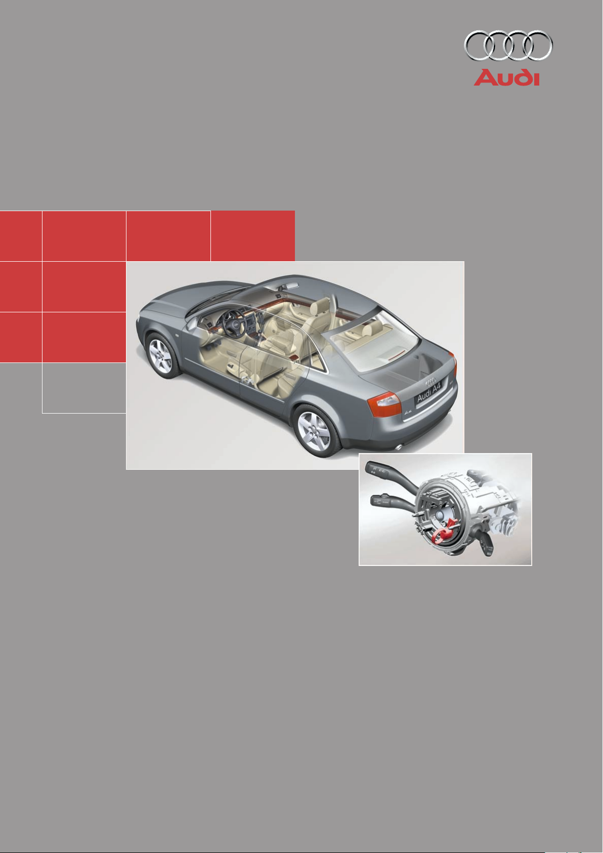
The new Audi A4,
a vehicle which combines driving pleasure and good sense
with the highest level of quality and sports styling.
Control unit for vehicle electrical system
New engine programme
...18
Electronic stability programme with
brake assistance
...32
Steering column switch module
Crash sensors for front airbag
...48
...44
...14
Trapezium link
rear axle
...27
Aero-floor
2
...7
Multi-communication bar
...72
Page 3

Contents
Page
Introduction . . . . . . . . . . . . . . . . . . . . . . . . . . . . . . . . . . . . . . . . . . 4
Body . . . . . . . . . . . . . . . . . . . . . . . . . . . . . . . . . . . . . . . . . . . . . . . . 8
Occupant protection . . . . . . . . . . . . . . . . . . . . . . . . . . . . . . . . 12
Engine and gearbox
2.0 l R4 and 3.0 l V6 engines (see SSP 255) . . . . . . . . . . . . . . . . . . . . . . . . . . . . . . . 18
Innovations - 2.5 l V6 TDI engine. . . . . . . . . . . . . . . . . . . . . . . . . . . . . . . . . . . . . . . . 19
Innovations - automatic gearbox . . . . . . . . . . . . . . . . . . . . . . . . . . . . . . . . . . . . . . . 23
Running gear
Axles . . . . . . . . . . . . . . . . . . . . . . . . . . . . . . . . . . . . . . . . . . . . . . . . . . . . . . . . . . . . 26
Mechanical unit mountings . . . . . . . . . . . . . . . . . . . . . . . . . . . . . . . . . . . . . . . . . . . 28
Brake system . . . . . . . . . . . . . . . . . . . . . . . . . . . . . . . . . . . . . . . . . . . . . . . . . . . . . . . 29
Brake assistance . . . . . . . . . . . . . . . . . . . . . . . . . . . . . . . . . . . . . . . . . . . . . . . . . . . . 32
Electrical system
Vehicle electrical system . . . . . . . . . . . . . . . . . . . . . . . . . . . . . . . . . . . . . . . . . . . . . . 36
CAN BUS system . . . . . . . . . . . . . . . . . . . . . . . . . . . . . . . . . . . . . . . . . . . . . . . . . . . . 38
Dash panel insert . . . . . . . . . . . . . . . . . . . . . . . . . . . . . . . . . . . . . . . . . . . . . . . . . . . . 40
Steering column switch module . . . . . . . . . . . . . . . . . . . . . . . . . . . . . . . . . . . . . . ..44
Function circuit diagram . . . . . . . . . . . . . . . . . . . . . . . . . . . . . . . . . . . . . . . 46
Control unit for vehicle electrical system . . . . . . . . . . . . . . . . . . . . . . . . . . . . . . . . 48
Function circuit diagram for "lowline" version . . . . . . . . . . . . . . . . . . . . . 50
Function circuit diagram for "highline" version . . . . . . . . . . . . . . . . . . . . 52
Convenience system . . . . . . . . . . . . . . . . . . . . . . . . . . . . . . . . . . . . . . . . . . . . . . . . . 58
Anti-theft alarm system . . . . . . . . . . . . . . . . . . . . . . . . . . . . . . . . . . . . . . . . . . . . . . . 63
Radio - chorus II, concert II and symphony II . . . . . . . . . . . . . . . . . . . . . . . . . . . . . 65
Navigation IV and Navigation Plus-D . . . . . . . . . . . . . . . . . . . . . . . . . . . . . . . . . . . . 69
Multi-communication bar . . . . . . . . . . . . . . . . . . . . . . . . . . . . . . . . . . . . . . . . . . . . . 72
Electric logbook "Audi Logbook" . . . . . . . . . . . . . . . . . . . . . . . . . . . . . . . . . . . . . . . 74
Heater/AC
Design and function . . . . . . . . . . . . . . . . . . . . . . . . . . . . . . . . . . . . . . . . . . . . . . . . . 76
7-piston compressor . . . . . . . . . . . . . . . . . . . . . . . . . . . . . . . . . . . . . . . . . . . . . . . . . 77
Air conditioner . . . . . . . . . . . . . . . . . . . . . . . . . . . . . . . . . . . . . . . . . . . . . . . . . . . . . . 78
Glove compartment cooling . . . . . . . . . . . . . . . . . . . . . . . . . . . . . . . . . . . . . . . . . . . 79
Solar roof. . . . . . . . . . . . . . . . . . . . . . . . . . . . . . . . . . . . . . . . . . . . . . . . . . . . . . . . . . . 80
Fresh air blower . . . . . . . . . . . . . . . . . . . . . . . . . . . . . . . . . . . . . . . . . . . . . . . . . . . . . 81
Actuators/sensors . . . . . . . . . . . . . . . . . . . . . . . . . . . . . . . . . . . . . . . . . . . . . . . . . . . 82
Functional diagram for fully automatic air conditioner . . . . . . . . . . . . . . 84
Additional heater . . . . . . . . . . . . . . . . . . . . . . . . . . . . . . . . . . . . . . . . . . . . . . . . . . . . 86
The self-study programme will provide you with information on
design and functions.
It is not intended as a workshop manual.
For maintenance and repair operations it is essential that you
refer to the current technical literature.
New
Important:
Note
3
Page 4
Introduction
The architecture of motion
Performance and smooth running
The engine programme of the new Audi A4
includes two petrol engines of a completely
new design, with aluminium housings.
The 2.0 litre 4-cylinder in-line engine with
96 kW (130 PS) and the 3.0 litre V6 with
162 kW (220 PS) fulfil the EU 4 emissions
standard.
A high degree of running smoothness is
achieved via balancer shafts.
Infinitely variable perfection
For the first time in this vehicle class, Audi
offers the infinitely variable "multitronic"
automatic gearbox for all front-wheel drive
versions.
The new light alloy running gear
With the four-link front axle, each wheel is
controlled by four aluminium transverse links.
The pivot bearings are also made from the
same light alloy.
The trapezium link rear axle for the quattro
drive system is also used in the front-wheel
drive models of the Audi A4.
4
Page 5
Finely-tuned aerodynamics
Despite the greater frontal area and the cooling air current for the air conditioner (standard), it was possible to improve the C
value
D
by 5 %, in comparison to its predecessor,
to 0.28.
A special feature is the so-called aero-floor,
which provides for optimal airflow on the
underside of the vehicle.
High safety standards
With a thoroughly optimised body design and
comprehensive safety equipment, the new
Audi A4 is able to comply with all current valid
safety standards, throughout the world.
Crash sensors for the front airbags integrated
directly into the bumper bar, improve occupant protection.
SSP254_048
Electronic stability programme (ESP)
including brake assistant
For the latest ESP generation, the hydraulic
brake assistant is an integral part of the
standard equipment.
It is intended to assist the driver by automatically increasing the brake pressure during
emergency braking.
Communication centre on wheels
With regard to infotainment, the new
Audi A4 leaves nothing to be desired.
4 different audio systems, 2 differently configured Navigation systems and a car phone
with voice operation are on offer.
5
Page 6
Introduction
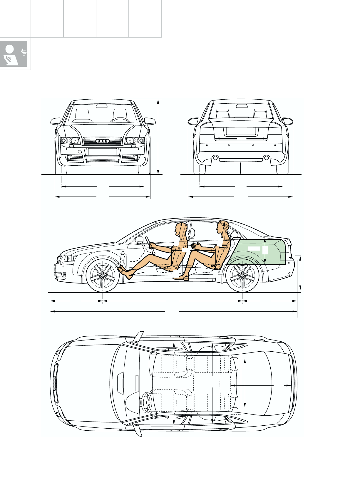
Vehicle dimensions of Audi A4´01
1628
1528
1766
977
799
1050
921 976
257
2650
870
303
901
106/110
1526
1937
1
5
9
445 L
471
976
4527
1000
1400
1357
1088
SSP254_051
6
Page 7
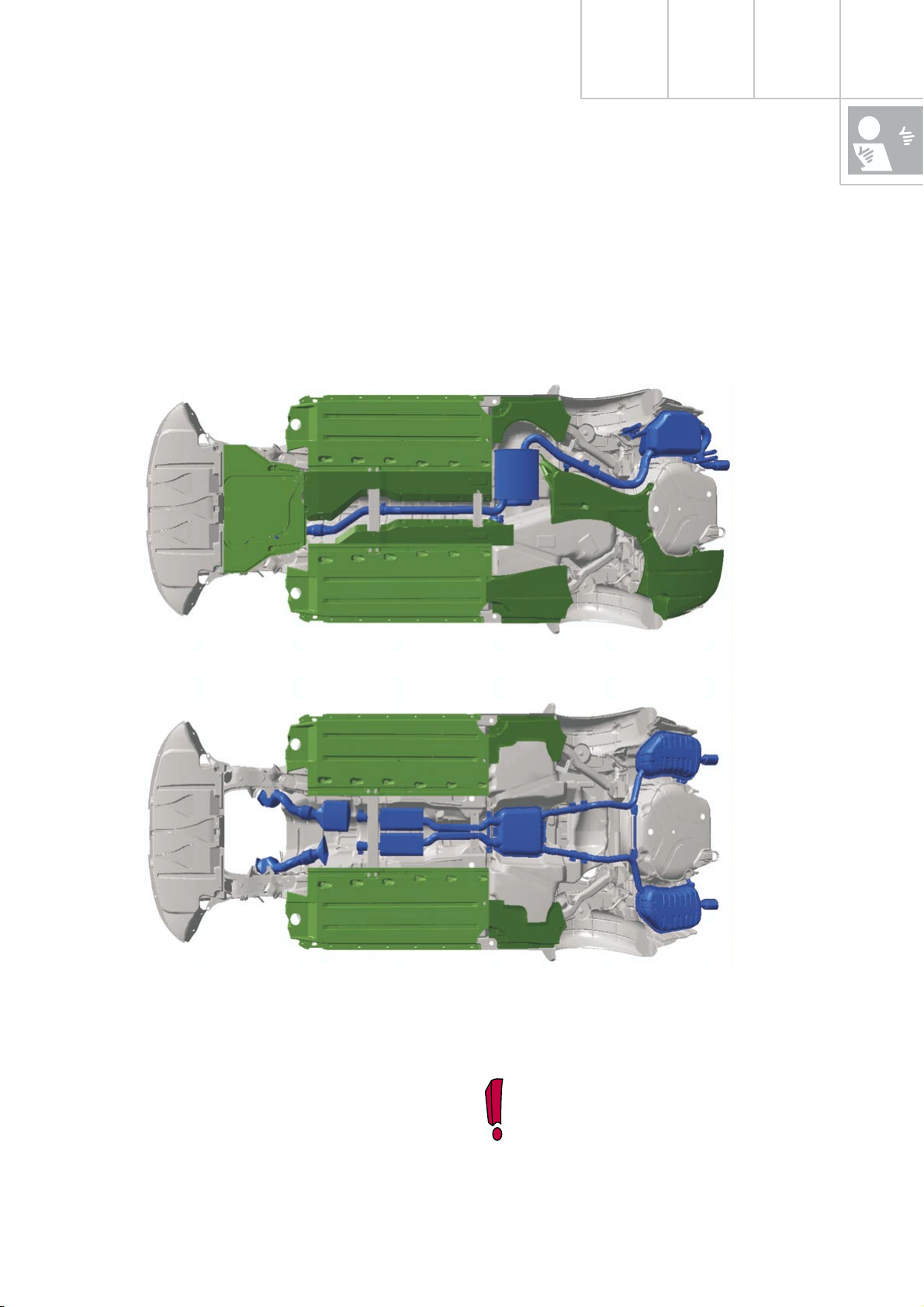
The aero-floor
not only contributes to improved aerodynamics.
It was also possible to reduce the noise level
by approx. 3 dB (A).
Front-wheel drive
The aero-floor was designed so as to guarantee ground clearance and resistance to stone
impact and to prevent accumulation of dirt,
stones and snow.
Four-wheel drive quattro and V6 engine
Part of the additional costs generated by the
aero-floor could be compensated by dispensing with certain panelling components as
well as by dispensing with PVC protection of
the underside of the vehicle. The latter is of
advantage during recycling.
SSP254_053
The engine compartment noise insulation does not form part of the aerofloor.
7
Page 8
Body
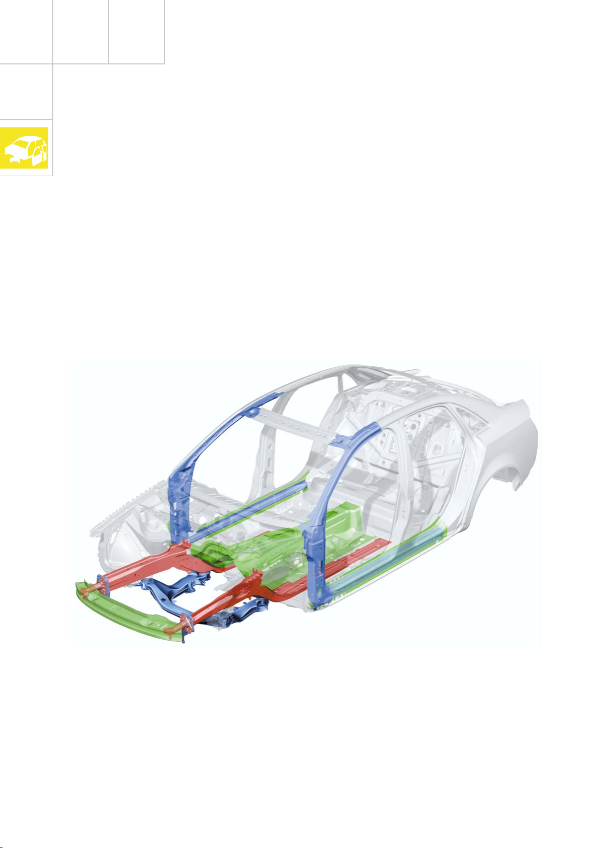
Front impact design features
The new Audi A4 is designed for optimal conformance with current crash requirements
and safety standards.
This could only be achieved by increasing the
body weight.
In order to reduce this additional weight to a
minimum, the proportion of light-weight
materials has been increased in comparison
to its predecessor.
The proportion of high-strength sheet metal
parts as well as the use of a total of 10 large
component "tailored blanks", contribute significantly to weight reduction.
Body rigidity has been increased by 45 % by
increasing the number of connection points
by 25 %.
– the straightened longitudinal member with
crash-optimised octagonal cross-piece
– the rigid and significantly wider bumper
cross-piece
– the integration of the member structures
into the passenger cell
– strength, rigidity and weight-optimised
suspension strut cross-piece
SSP254_054
Depending upon vehicle weight, performance and fuel consumption are the characteristics
which our customers can experience at first hand.
8
Page 9
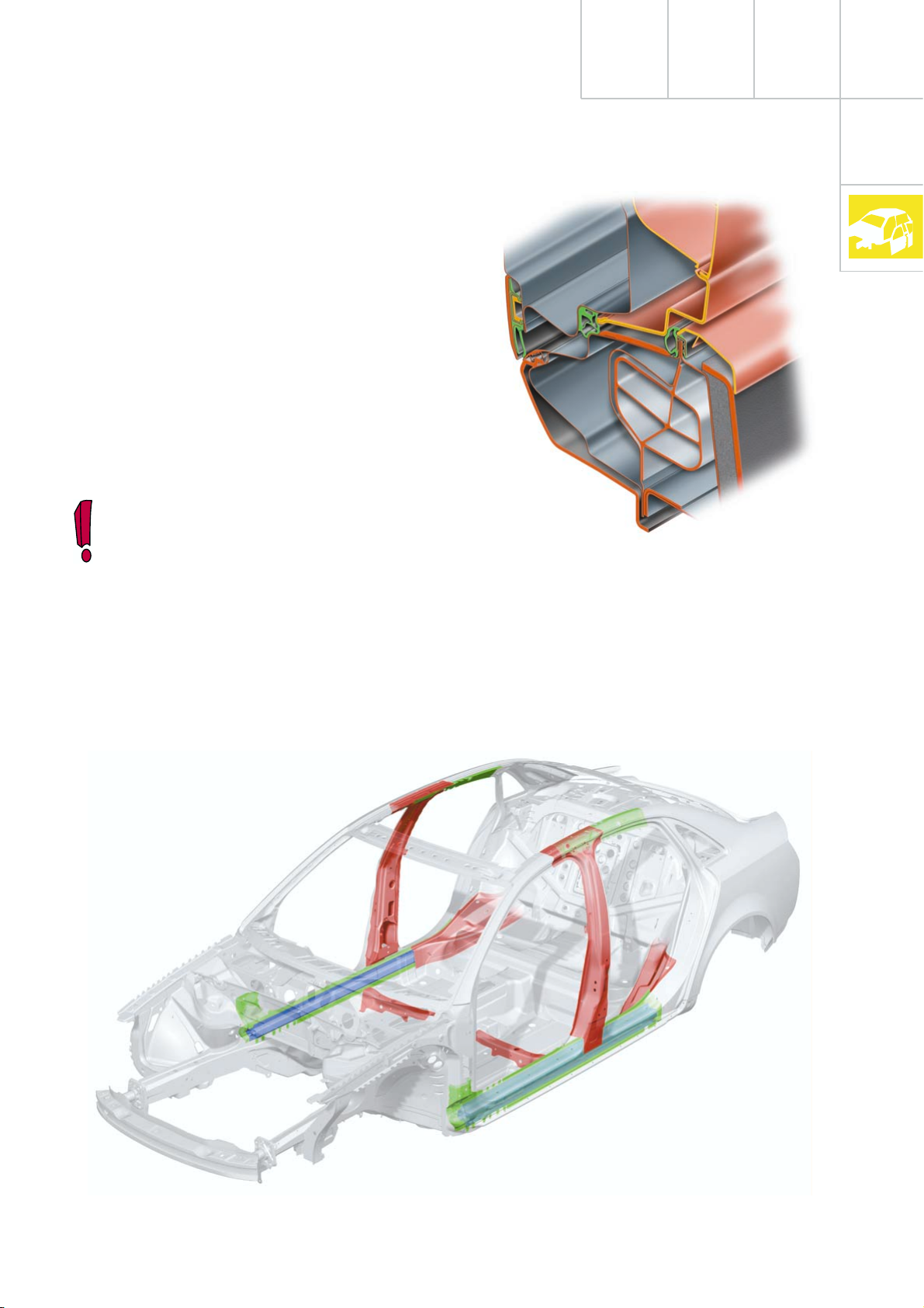
Side impact design features
In the floor area, the cell consists of three
large tailored blanks, which ensure a stable
connection between the front and rear of the
vehicle.
Weight-saving optimisation of deformation
characteristics in the event of a side impact
was achieved by the use of an aluminium
extruded profile in the sill.
“tailored blanks” are made-to-measure
sheet metal parts with varying material
thickness.
SSP254_055
SSP254_056
9
Page 10
Body
w
w
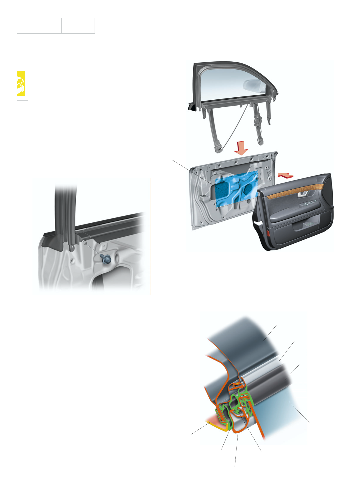
Doors
The doors of the Audi A4 demonstrate a significantly increased rigidity due to the onepiece door shell construction.
For the first time, a so-called spray-on noise
insulation is used, which is sprayed on as
required and allows weight reduction for the
same effectiveness.
Noise insulation
SSP254_066
In addition, the doors have been fitted with a
second weatherseal. One weatherseal is fitted
to the door and the other is fitted to the body.
The new door concept permits a reduction in
the overall noise level of a further 3 dB (A) and
thus contributes to improving the aero-acoustics.
SSP254_067
The newly developed sub-frame is bolted to
the door shell via fitted bolts.
Roof
Roof trim strip
Door windo
seal
Door windo
Door trim
Door seal
Door frame
Door frame seal
SSP254_075
Page 11
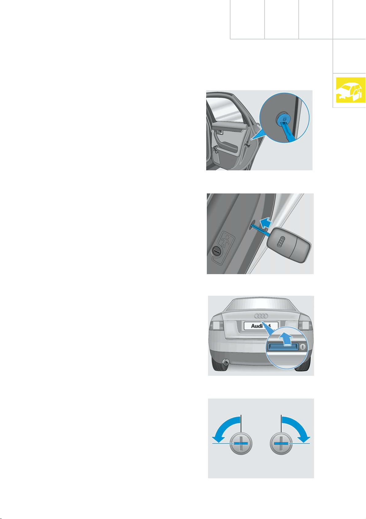
Emergency door locking
In the event of failure of the central locking,
e.g. due to power supply faults, each door can
be individually locked without using the lock
cylinder.
Firstly, with the door open, the cap must be
removed. Emergency locking is effected by
inserting the ignition key.
After the door has been closed, it is not possible to open it from the outside.
The door can be opened from the inside by
actuating the door release handle twice.
SSP254_069
Luggage compartment lid
The luggage compartment lid should always
be operated via the radio remote control.
The lock cylinder for the luggage compartment lid is integrated into the handle.
Continuous locking of luggage compartment
If the lock cylinder is in the horizontal position with the key removed, the luggage compartment lid is no longer included in the
central locking system. Opening is then only
possible via the centre unlocking button of
the radio remote control.
When the lock cylinder is in the vertical position, the lid is an integral part of the central
locking system.
SSP254_070
Manual unlocking and opening
is effected by turning the key to the left.
In this position, it is not possible to remove
the key, which must subsequently be returned
to the vertical position.
Thus, it is ensured that the luggage compartment lid is an integral part of the central locking system.
SSP254_071
SSP254_072
11
Page 12
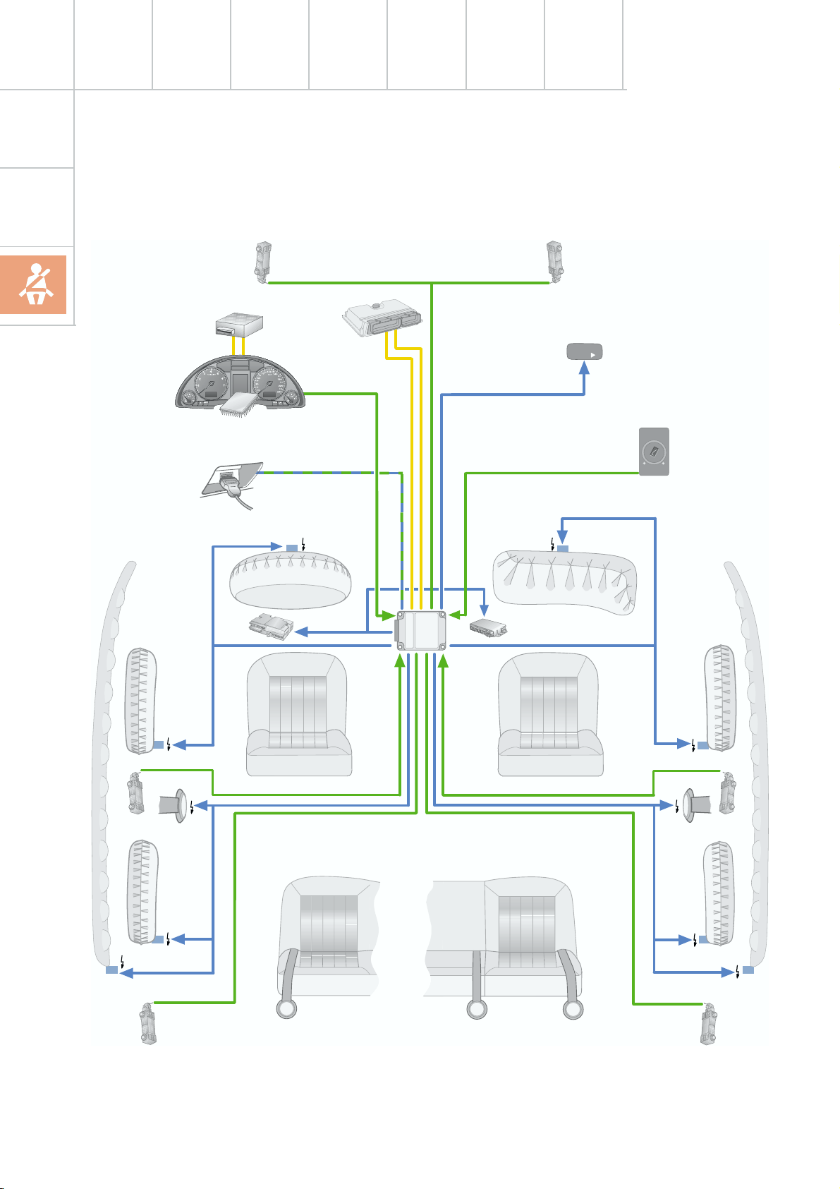
Occupant protection
Overview of system
J285/K75
J533
T16
J393
G 283
J162
N95
J220
J234
G 284
J526
K145
AIRBAG
OFF
N131
AIRBAG
AUS
E224
EIN
12
N277
G 256
G179
N199
N153
N201
N200
N154
N202
G180
N278
G 257
SSP254_029
Page 13

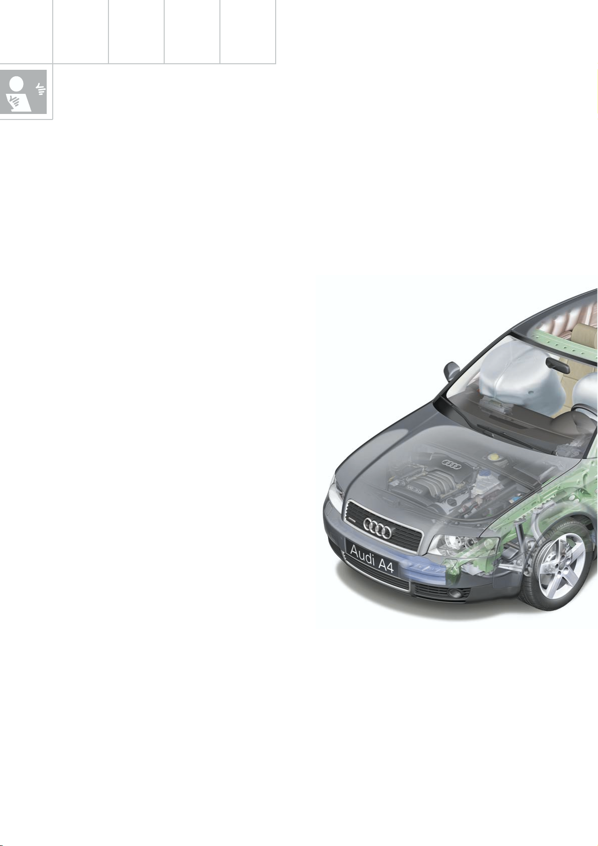
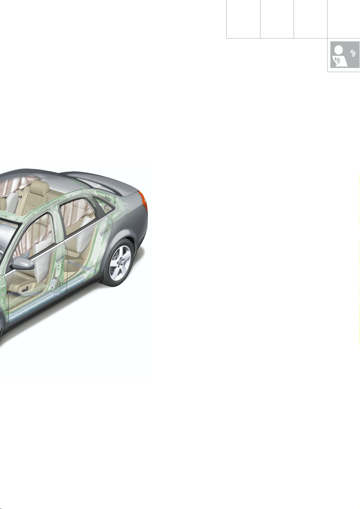
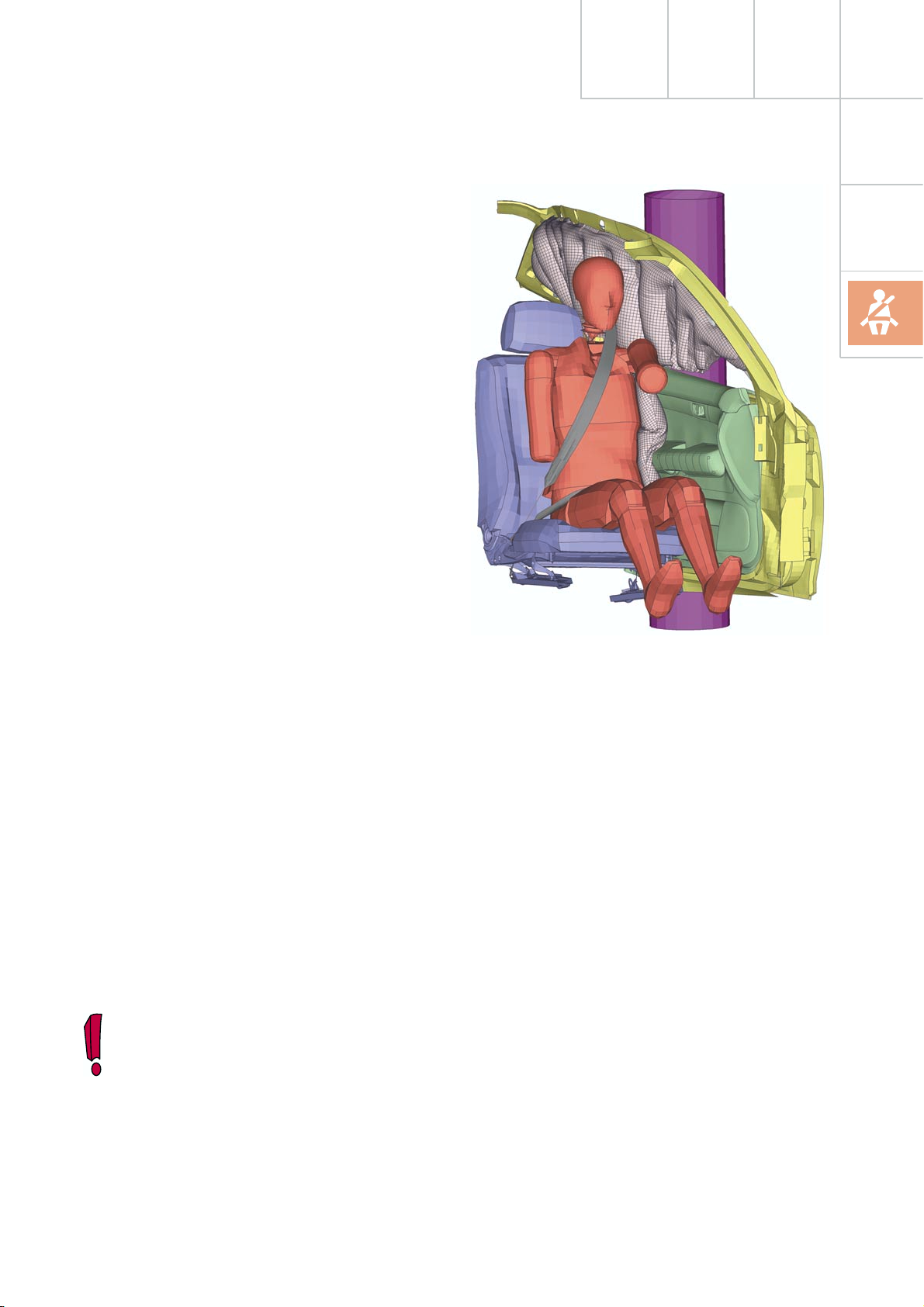
To complement the comprehensive body
modifications, occupant protection has been
improved through the further development of
the familiar 8.4 airbag system.
The new generation bears the designation 8.4 E, where the E stands for
"extended".
The position of the sensors is selected so that
they are installed as near as possible to the
outer structure of the vehicle.
This enables quicker deceleration detection in
the event of an impact.
The system comprises driver/passenger airbags, front side airbags, optional rear side
airbags, SIDEGUARDS
®
, three point front seat
belts with ball tensioners and belt force limiters, three point rear outer seat belts, centre
lap belt (for fixed rear seat bench), Isofix preparation in rear of vehicle, and a total of 6
non-central accelerometers:
– 2 front impact crash sensors
– 2 driver/passenger side airbag crash sen-
sors, (in the B-pillar for side impact)
– 2 driver/passenger rear side airbag crash
sensors, (on the C-pillar for side impact)
The external sensors deliver digitised acceleration data to the airbag control unit, which is
then evaluated in the control unit and which
triggers the relevant restraint system components.
Key
E224 Key switch for switching off
passenger’s side airbag
G179 Side airbag crash sensor, driver’s
side (B-pillar)
G180 Side airbag crash sensor, passenger’s
side (B-pillar)
G256 Crash sensor for rear side airbag,
driver’s side
G257 Crash sensor for rear side airbag,
passenger's side
G283 Front airbag crash sensor, driver’s
side
G284 Front airbag crash sensor,
passenger’s side
J162 Heater control unit
J220 Control unit for motronic
J234 Airbag control unit
J285 Control unit with display unit in
dash panel insert
J393 Central control unit for convenience
system
J526 Control unit for telephone /
telematics
J533 Diagnosis interface for data bus
(Gateway)
K75 Airbag warning lamp
K145 "Airbag off" warning lamp,
passenger's side
N95 Airbag igniter, driver's side
N131 Airbag igniter 1, passenger's side
N153 Igniter for belt tensioner, driver's side
N154 Igniter for belt tensioner,
passenger's side
N199 Igniter for side airbag, driver’s side
N200 Igniter for side airbag, passenger's
side
N201 Igniter for rear side airbag,
driver’s side
N202 Igniter for rear side airbag,
passenger's side
N277 Igniter for airbag in B-pillar
(SIDEGUARD
®
), driver's side
N278 Igniter for airbag in B-pillar
(SIDEGUARD
®
), passenger's side
T16 Connector, 16-pin, diagnosis
connection
13
Page 14
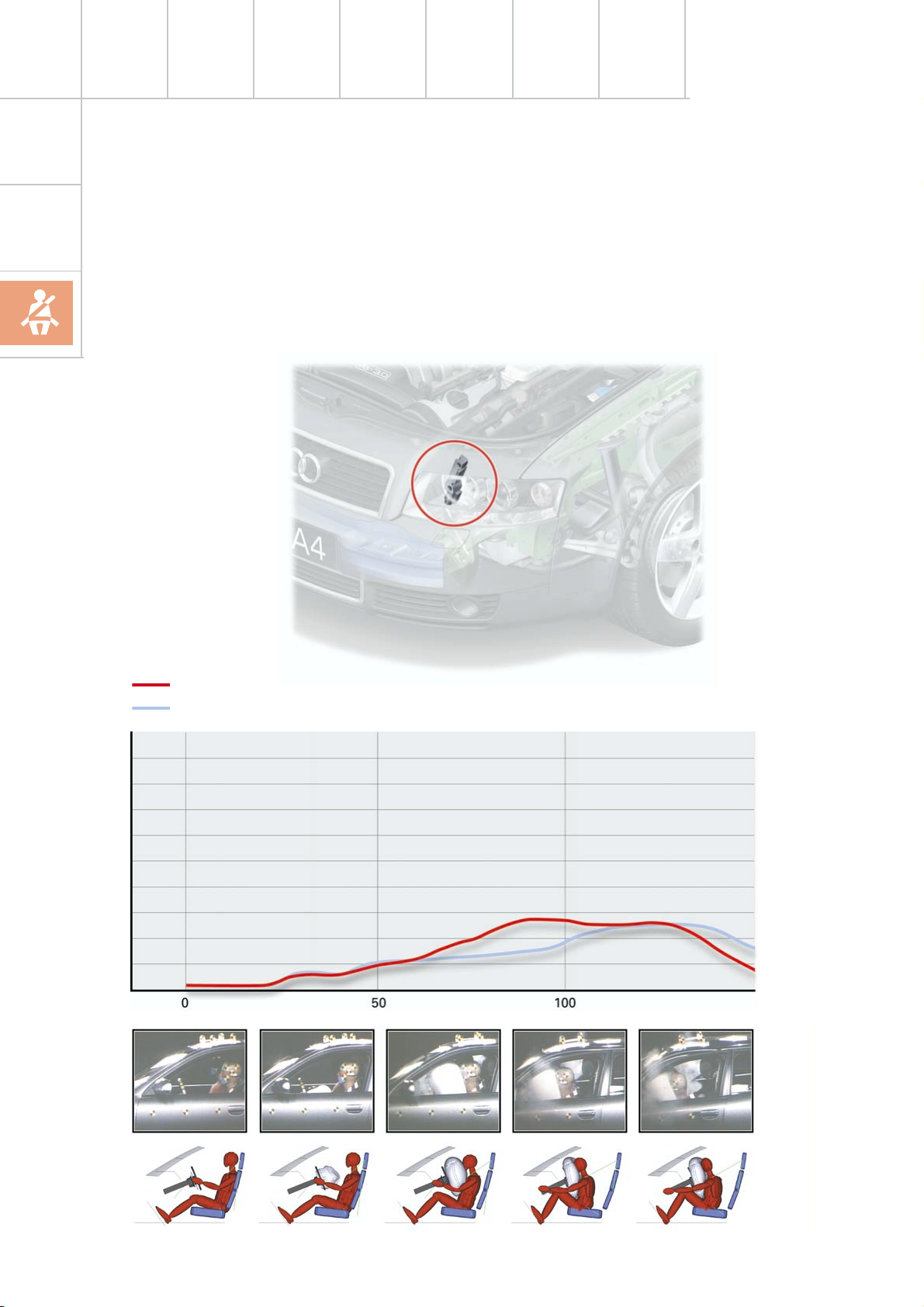
Occupant protection
Crash sensors for front airbag G283, 284
Both sensors for front impact detection function in conjunction with the crash sensor and
the safe sensor which are integrated into the
airbag control unit J234.
If a certain signal threshold is exceeded in the
front airbag crash sensor, a threshold reduction is activated in the airbag control unit,
which results in a shorter triggering time.
Upper body
Head
Deceleration load
Impact
Belt force limiter
Front airbags inflated
Triggering of front airbags
Triggering of belt tensioners
Damping function
response in
response
Time [ms]
SSP254_058
the steering column
Vehicle rebound
SSP254_063
14
SSP254_064
Page 15
Crash sensors for side airbags
G179, 180, 256, 257
In order to trigger the components of the
restraint system, two simultaneous impact
detection signals are required for the plausibility check:
– from both opposing crash sensors
(B-pillar left with right and/or
(C-pillar left with right) and
– from the control unit internal crash sen-
sors.
The crash sensors are designed in such a way
that incorrect installation is excluded.
Airbag control unit J234
The warning lamp for airbag K75 is activated
continuously following a detected impact.
"CRASH DATA STORED" and the triggered
components are displayed with fault code
during fault memory readout.
SSP254_059
Re-encoding of the airbag control unit is no
longer possible after the first crash data message is stored.
Triggering is performed in two thresholds
depending upon the deceleration value:
– Threshold 1 = belt tensioners only
– Threshold 2 = belt tensioners and airbag(s)
Sensors and components to be replaced
following an accident, are listed in the
current workshop manual.
15
Page 16
Occupant protection
a
a
a
a
a
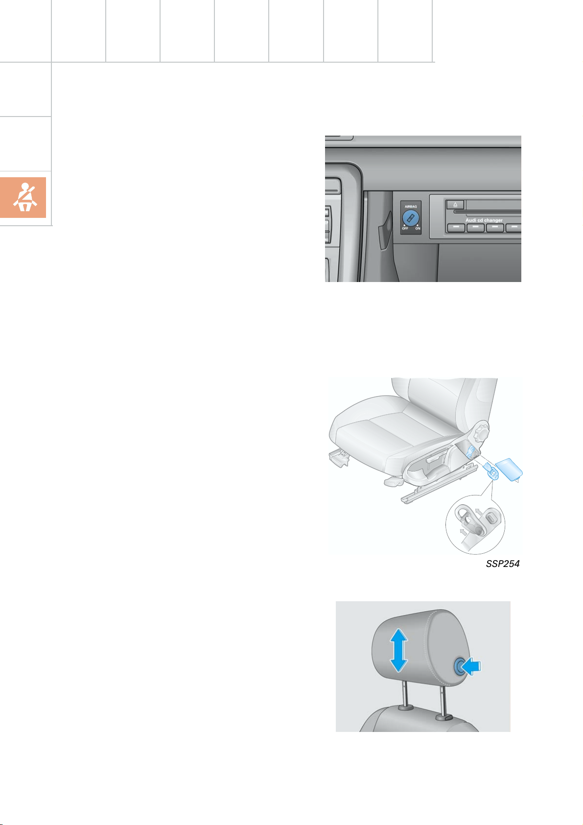
Deactivation of passenger airbag
Deactivation of the passenger airbag is only
possible via the key switch. In the Audi A4, the
passenger's side airbag is also deactivated.
Deactivation via the diagnostic tester is not
possible.
If a customer requires the deactivation function where a key switch is not fitted, this can
only be achieved by retrofitting the key switch
and airbag OFF lamp and by re-encoding of
the airbag control unit.
Front belt attachment
Belt lock and strap fastenings are permanently connected to the seat frame. Thus, in
conjunction with the seat belt height adjuster,
an optimal belt fitting can be achieved for
each seat position.
SSP254_101
SSP254_011
Front head restraints
In order to offer a high degree of occupant
protection in conjunction with the seat belt
and airbag, the front head restraints have
been supplemented by an integral locking
mechanism.
SSP254_102
16
Page 17

Crash signal processing
There are two separate crash signal outputs:
One crash signal is output via the conventional wiring and triggers the following functions:
– Transmitting an emergency call via the
control unit for telephone/telematics J526
(optional)
– unlocking the vehicle,
– Switch on interior light
(switch must be set to door contact),
– switching on hazard warning lights via the
central convenience electronics J393.
The auxiliary heater J162 (optional) is
switched off by the central convenience
electronics J393 via a CAN convenience
message.
The second crash signal output functions via
the convenience CAN bus, which switches off
the engine fuel supply via the engine control
unit J220.
17
Page 18
Engine and gearbox
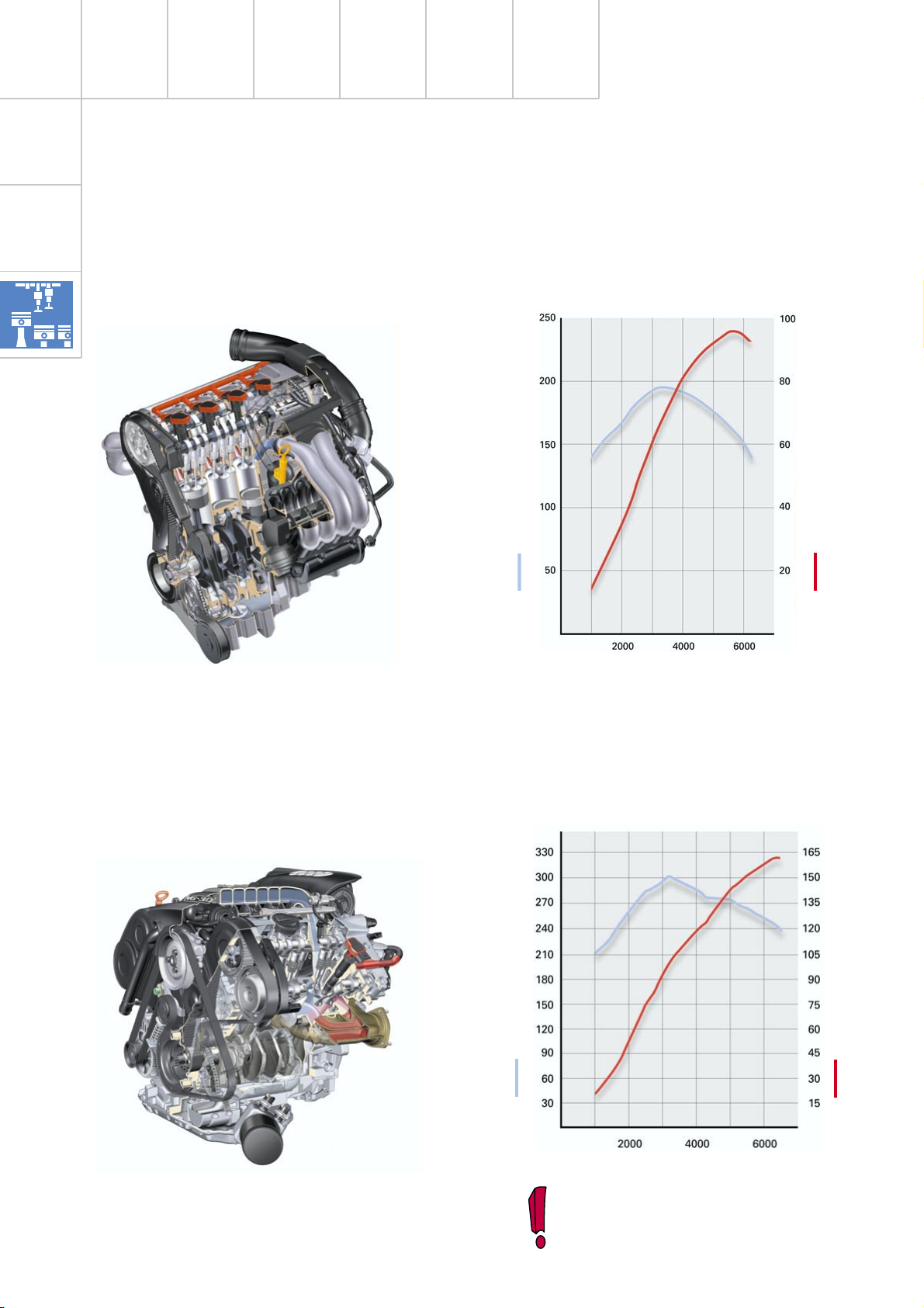
Engine
The 4-cylinder, 2.0 l engine
provides high propulsive force due to the
maximum torque of 195 Nm at 3300 rpm.
SSP254_038
The 3,0 l V6 engine
with five-valve cylinder head, produces162 kW
(220 PS) at 6300 rpm from 2976 cm
The maximum torque of 300 Nm is developed
at 3200 rpm.
3
.
Torque [Nm]
Engine speed in rpm
Power output [kW]
SSP254_060
18
SSP254_030
Torque [Nm]
Engine speed in rpm
Detailed information on these engines
can be found in SSP 255.
SSP254_061
Power output [kW]
Page 19
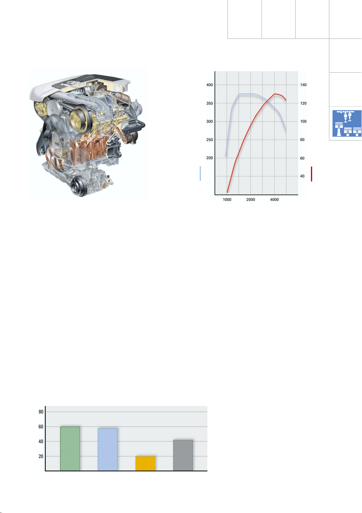
Innovations 2.5 l V6 TDI engine
SSP255_045
Technical data
Capacity: 2496 cm
Bore: 78.3 mm
Stroke: 86.4 mm
Compression: 18.5 : 1
3
Injection system: Bosch VE VP 44 S3.5
Turbocharger: VNT 20
Exhaust emissions class: EU 3
Consumption: urban 11.0 l/100 km
(6-gear, quattro) country 6.1 l/100 km
Power output: 132 kW (180 PS)
Torque: 370 Nm at 1500 rpm
The main features of the basic engine are the
same as those of the familiar V6 TDI engine
with 132 kW (180 PS).
Torque [Nm]
Engine speed in rpm
SSP255_039
Power output [kW]
average 7.8 l/100 km
The injection system was modified in order to
reduce exhaust gas and particle emissions.
Power output and torque curve values could
be maintained under conditions which were
well within EU 3 limit values.
Limit value [%]
NOx
HC+NOx
CO
EU 3 limit values 100 %
Particle = 0.05 g/km
CO = 0.64 g/km
HC+NOx = 0.56 g/km
NOx = 0.50 g/km
Particle
SSP255_038
19
Page 20
Engine and gearbox
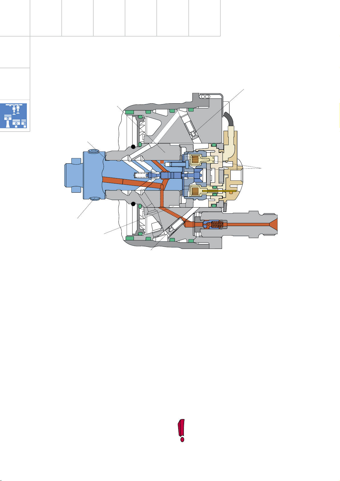
Injection pump VP 44 S3.5
Distributor bushing
Distributor shaft
Forced flush
return
Supply piston
Thermal shoulder
Forced flush feed
The high pressure section of the injection
pump has been redesigned with regard to
pressure levels and quicker solenoid valve
actuation.
The injection pressure at part throttle has
been increased by the following measures:
Solenoid valve
SSP255_040
In order to initiate pre-injection for cold and
warm engines, the solenoid valve dynamics
have been significantly increased.
The associated increased heat generation in
the solenoid valve, is compensated by
improved fuel flow and optimal filling of the
high pressure section is achieved.
– increased cam stroke from 3.5 to 4.0 mm
– more stable support structure for high
pressure section on pump body
– conversion from 3 pistons with a diameter
of 6.0 mm, to 2 pistons with a diameter of
7.0 mm.
By reducing the number of high-pressure pis-
tons from 3 to 2, it was possible to reduce
high-pressure leakage via the sealing sur-
faces.
20
Noise levels have been significantly improved
by the pre-injection for cold and warm operation and the use of dual-spring nozzle holders.
Previously, pre-injection via the solenoid
valve was only realised during the engine
warm-up phase.
Page 21
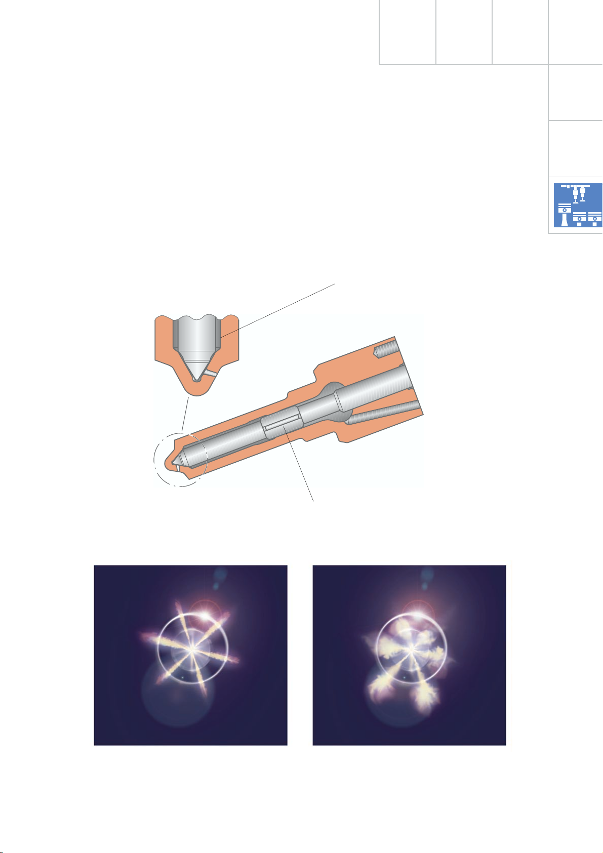
Injector
For the first time, an ICU injector ( I nverse C avity U ndercut) is used, which has a dual needle
guide.
The advantage of this ICU geometry is a significantly improved spray formation, especially in the part throttle range for small
injection quantities and short needle lift.
Due to the improved spray formation through
the use of the ICU injector, it was possible to
reduce the exhaust emissions and the particle
values by up to 20 %.
ICU seat geometry
SSP255_041
Dual needle guide
ICU seat geometry Standard seat geometry
SSP255_042
21
Page 22
Engine and gearbox
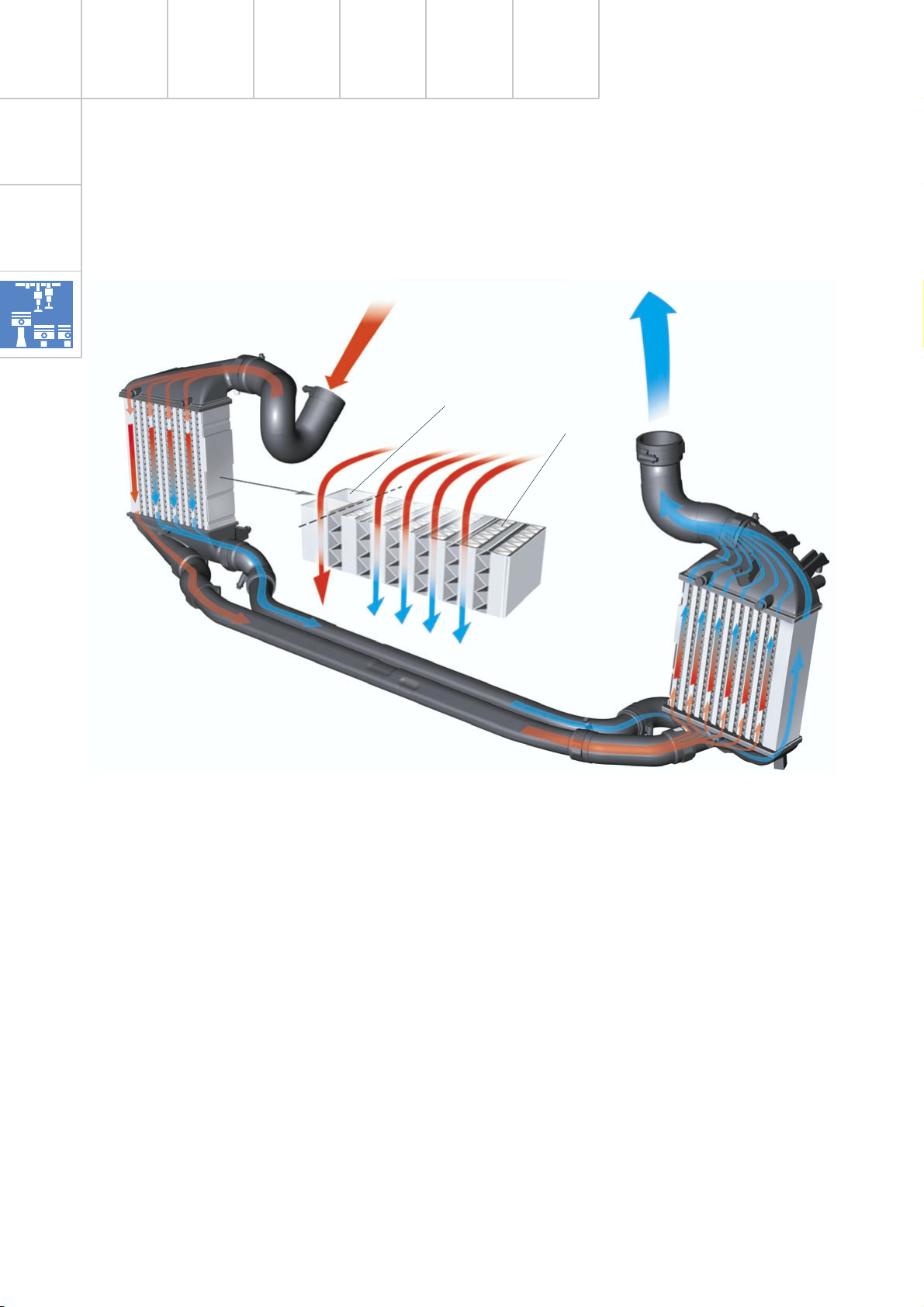
Charge air cooler
Through duct
Cooling duct section
The existing series connection of the two
charge air coolers for the 110 kW engine is
inadequate for the 132 kW engine with its
high air throughput.
A new charge air cooler design was devel-
oped, in order to ensure optimal charge air
flow.
22
SSP255_043
The charge air cooler design comprises two
sections, in which part of the charge air is fed
via a through duct, connected to a space-saving pipe, to the section of the other charge air
cooler which is fitted with cooling fins.
The rest of the charge air is fed directly
through the cooling fins, via a separate pipe,
to the second charge air cooler and into the
through duct.
Page 23
Innovations - automatic
gearbox
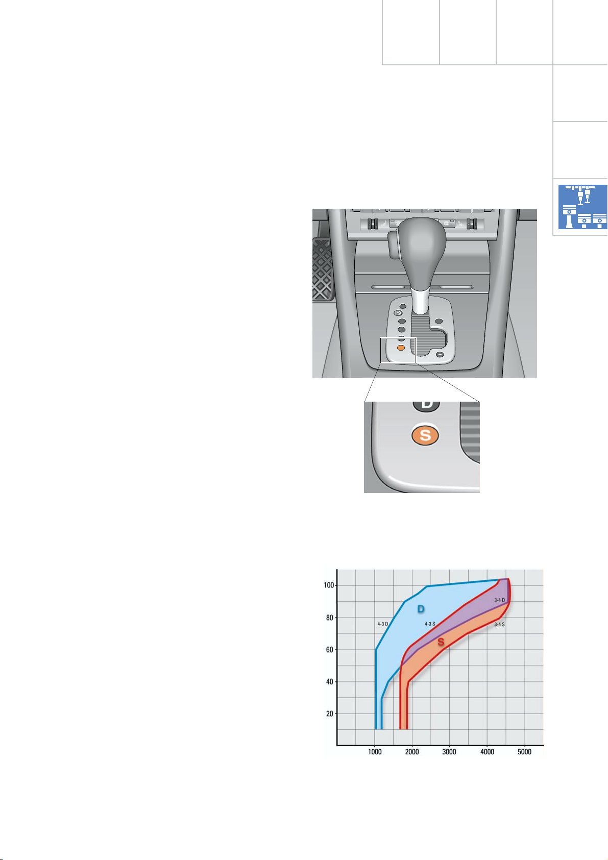
5-speed 01V automatic gearbox
The Audi A4 quattro MJ01 with 5-speed automatic gearbox features a new shift lever gate,
together with a new shifting concept.
The existing selector lever positions, 4,3,2 are
discontinued and are replaced by the "S"
position.
Gearshift positions 4,3,2 have been discontinued as they are hardly ever used in practice.
The DSP (dynamic shift programme) and "tiptronic" function have basically rendered them
superfluous.
P
R
N
D
S
+
With the selector lever is in the "S" position, a
sports shift programme provides the relevant
driving dynamics. In position "S", the DSP
also provides for adaptation of the driving set
values to the driving conditions.
The introduction of the "S" programme enables a significant extension of the useful shift
range between economy and sports.
The "S" programme comprises the following
special features:
– If, during driving with constant accelerator
pedal position, the selector lever is set to
the "S" position, the system always shifts
down, within defined limits.
– In order to achieve a direct driving reaction
in response to accelerator pedal actuation,
the converter clutch is closed during driv-
ing operation, where possible.
– If, in conjunction with the overall gearbox
ratio, 5th gear is designed as overdrive
gear (overdrive, 4+E), only 1st -4th gears
are shifted.
SSP254_117
Example: Dynamics code 40
Shift map 1
We recommend the multi-function steering
wheel (available as optional extra) with steering wheel "tiptronic" ("thumb shifting").
Throttle valve angle [%]
Gearbox output speed [rpm]
D - normal driving programme
S - sports driving programme
SSP254_103
23
Page 24
Engine and gearbox
"multitronic" and 5-speed automatic gearbox
An innovation for all automatic gearboxes is
the "Tip in D " function. This means that the
steering wheel "tiptronic" function is now
also available in selector lever position "D".
The transition to the "tiptronic" function is
effected by actuating one of the two tip
switches on the multi-function steering wheel
(selector lever in position "D"). The system
then switches to the "tiptronic" function for
approx. 10 seconds. All gears can be shifted
within the range of permissible engine
speeds.
The system returns to normal automatic oper-
ation approx. 10 seconds after the last tip
request.
SSP254_088
Special feature:
The countdown from approx. 10 seconds to
return to normal automatic operation is interrupted, in the event that cornering is detected
or the vehicle is in overrun operation.
When normal driving conditions are detected
again, the countdown recommences from
approx. 10 seconds.
24
Page 25

Notes
25
Page 26
Running gear
Axles
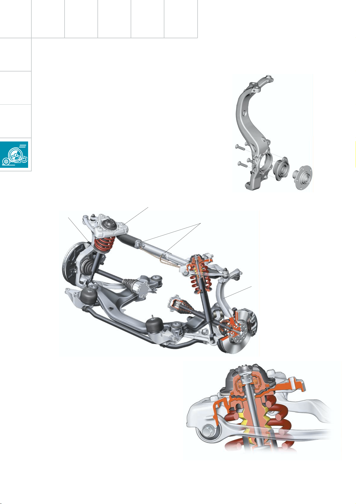
Four-link front axle
The thorough further development of the
light-weight construction resulted in a weight
reduction of approx. 8.5 kg at the front axle.
In addition to all transverse links, the pivot
bearing is now also made of aluminium.
The wheel bearing is attached to the pivot
bearing via four bolts. The wheel hub can be
pressed in and out.
Aluminium
spring plate
SSP254_086
Aluminium mounting bracket
Shock absorber valves
SSP254_087
Aluminium pivot bearing
The suspension strut mounting is of the bulky
rubber bearing construction.
It consists of two functional components:
– The inner part forms the connection to the
piston rod.
– The larger outer part provides for acoustic
insulation of the shock absorber.
26
SSP254_085
Page 27
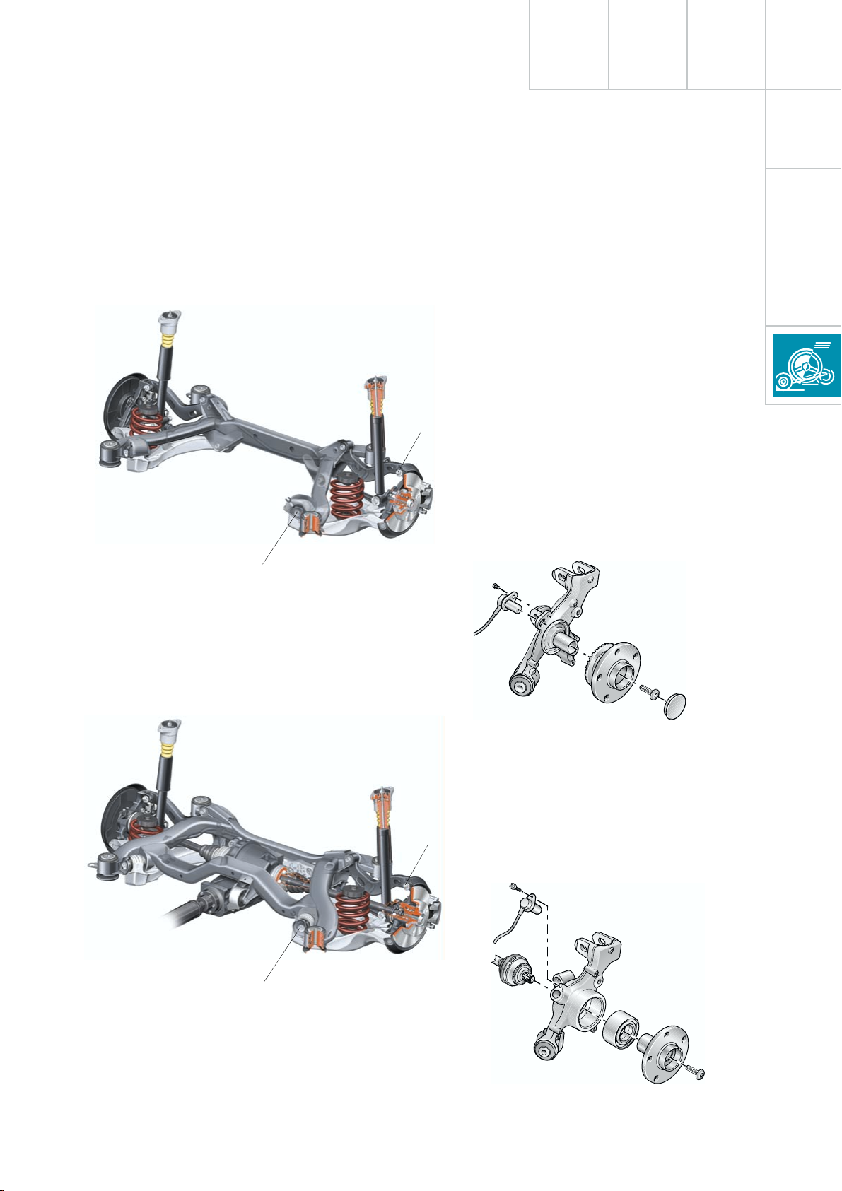
Trapezium link rear axle
The rear axle design with largely identical
components is used in both the front-wheel
drive as well as in the quattro versions.
SSP254_089
Toe adjustment
The front-wheel drive version is fitted with a
wheel bearing unit with integral wheel hub,
which is mounted on a stub axle forged
together with the wheel carrier.
Apart from the axle mounting, the two axle
versions differ only in the wheel carrier and
the wheel bearings.
Camber
adjustment
SSP254_091
Toe adjustment
The wheel bearings of the quattro version
consist of pressed-in, double-row angular ball
bearings with conventional wheel hubs.
SSP254_083
Camber
adjustment
SSP254_082
27
Page 28

Running gear
Mechanical unit mountings
Engine mounting 1
Cross member
Torque
member
Engine
mounting 2
A newly designed three-point mechanical unit
mounting is used in the new Audi A4.
The hydraulically damped engine mountings
(electrically-controlled version for diesel
engines) are fastened directly to the longitu-
dinal members via die-cast aluminium brack-
ets.
The gearbox mounting is effected by means
of a conventional rubber bearing on a body-
mounted aluminium carrier, which is pro-
duced according to the hollow sand casting
technique.
Gearbox
mounting 3
SSP254_107
The additional cross member enables support
over a longer lever arm, which positively influences vibration and load cycle characteristics.
The aluminium cross member is bolted to the
body as well as to the rear subframe mountings and, in addition to its supporting function for the gearbox mounting, serves as a
body-stiffening tunnel bridge.
28
The three-point mechanical unit mounting is used for all engine/gearbox
combinations except those including
the 01V 5-speed automatic gearbox.
Page 29

Brake system
The new Bosch ESP 5.7 is introduced in the
Audi A4. The ESP 5.7 is distinguished by the
following special features:
– The hydraulic unit and control unit form a
single unit.
– The charging pump (actuation of ESP
hydraulic pump V156) is discontinued.
– A brake assistant is included.
Hydraulic modulator
Due to the increased brake fluid viscosity at
extremely low ambient temperatures, the
required delivery rate for the return pump for
ABS V39 could not be achieved without a
charging pump (resulting from the increased
suction resistance in the system).
The purpose of the development of the
ESP 5.7 was to improve the suction of the ABS
return pump so that the charging pump was
no longer necessary.
The charging pump could be discontinued
through the use of a two-stage ABS return
pump, enlarging the cross-section of the
brake lines and the use of a larger-dimensioned central valve in the brake master cylinder.
SSP254_094
29
Page 30

Running gear
Single-stage ABS return pump
Suction volumes
The graphic shows a comparison of the
suction volumes of both pump versions.
In the single-stage ABS return pump, the
entire suction volume must be drawn in and
flow through the suction line during one
piston stroke (piston stroke from TDC to BDC).
Suction volumes
SSP254_095
The suction pressure is correspondingly high
and increases with increasing viscosity.
Cavitation and the associated drop in
performance on the pressure side, are the
results.
30
Page 31

Two-stage ABS return pump
Working chamber 1
Working chamber 2
Suction volumes
The piston of the two-stage ABS return pump
is stepped and has a double-acting function
within two working chambers.
Suction is effected in two stages; brake fluid
being drawn through the suction line during
each piston stroke.
Function:
If the piston moves from BDC to TDC, the
brake fluid in working chamber 1 is compressed whereas working chamber 2 is simultaneously under suction.
If the piston then moves from
TDC to BDC, the brake fluid which has been
drawn into working chamber 2 is forced back
into the suction line against the inlet valve.
SSP254_096
As the entire suction volume is supplied
almost continuously, the maximum suction
flow rate is significantly lower, which diminishes the suction pressure and prevents
cavitation.
Thus, a quick pressure build-up is ensured,
even at extremely low temperatures.
In working chamber 1, brake fluid is now
drawn via the open inlet valve, out of the suction line and out of the connection line to
working chamber 2.
The suction flow rate in the suction line is
diminished by that amount which flows back
out of the connection line from working
chamber 2
(drawn in during previous working operation).
31
Page 32

Running gear
Brake assistant
Investigations in accident research have
shown, that the majority of drivers fail to ade-
quately actuate the brakes in an emergency
situation.
This results in insufficient brake pressure
being generated to achieve maximum vehicle
deceleration.
This lengthens the braking distance.
Brake servo pressure sensor G294 is used for
detection of emergency braking.
Pressure sensor G294
During emergency braking, the brake assistant aids the driver by increasing the brake
pressure automatically, to a level exceeding
the locking limit.
The ABS ( A nti-lock b raking s ystem) is thus
quickly brought into the operating range,
which enables a maximum vehicle deceleration to be achieved.
For this purpose, the pressure increase gradi-
ent (pressure build-up with respect to time) is
evaluated and, if necessary, the brake assist-
ant is activated.
SSP254_093
Pressure [p]
Time [t]
SSP254_092
Emergency braking
32
Normal braking distance
Page 33

The function of the brake assistant is
sub-divided into 2 phases:
• Phase 1
If the pressure increase gradient exceeds a
specified value (emergency braking), the ABS
return pump and the relevant solenoid valve
are activated by the ESP control unit and the
brake pressure is thus increased into the ABS
• Phase 2
If the pressure determined by the driver falls
below a certain value after triggering of the
brake assistant, the system pressure is
restored to the pedal pressure determined by
the driver.
control range, in a similar manner to that of
the control system for an electronic differential lock.
Brake assistant activated Brake pedal unloaded Brake assistant
switches off
Phase 1
Phase 2
Brake pressure [p]
Time [t]
Brake pressure determined by an
experienced driver
Regulated brake pressure
(brake assistant)
Determined brake pressure
insufficient inexperienced driver
ABS control
range
SSP254_084
The integral inlet and outlet valves in the
hydraulic modulator are no longer simply switched on/off, but are regulated
via supplied voltage.
This enables more precise control on
extremely slippery surfaces, e.g. ice.
33
Page 34

Running gear
Brake fluid reservoir
The brake fluid reservoir is secured with an
additional screw.
The new maintenance opening in the brake
fluid reservoir enables the extraction of brake
fluid from both brake fluid chambers.
The new brake filler and bleeder unit
VAS 5234 must be used for this purpose.
Maintenance opening
Brake light switch
The fastening and adjustment of the brake
light switch are new.
The brake light switch is secured to the pedal
bracket via a bayonet fitting.
The position of the push rod is adjusted for
the basic setting.
For this purpose, the brake light switch must
be released by turning it anti-clockwise.
The push rod catch is released simultaneously via the locking lug.
SSP254_098
Fastening screw
The push rod is now free and can be adjusted
without risk of damage.
The push rod is pulled out to the stop for the
basic setting.
The brake light switch can now be inserted
into the pedal bracket and secured by turning
clockwise. At the same time, the push rod
catch is locked automatically by means of the
locking lug.
34
SSP254_099
Page 35

Notes
35
Page 36

Electrical system
Vehicle electrical system
Control unit for
telematics J499
Control unit for
mobile phone control
electronics J412
Battery
Control unit with
display in dash panel
insert J285
Control unit for headlamp
range control J431
Chip card
reader R99
Control unit for
coolant fan,
Stage 1+2 J293
Front airbag crash sensor, driver’s side G283
Front airbag crash
sensor, passenger’s side G284
Control unit
for ESP J104
Control unit
for Motronic J220
Control unit for automatic gearbox J217
Steering column
switch module J527
36
Page 37

Side airbag crash sensor,
passenger’s side G180
Door control units,
passenger side J387
rear right,
optional J389
Side airbag crash sensor, rear
driver’s side G256
passenger’s side G257
Control unit for trailer
recognition J345
Control unit for
parking aid J446
ESP sensor
Control unit for
tyre pressure
monitor J502
Airbag control
unit J234
Central control unit for
convenience system J393
Side airbag crash sensor,
driver’s side G179
Control unit for vehicle electrical system J519
SSP254_008
Door control unit,
driver’s side J386,
rear left, optional J388
37
Page 38

Electrical system
CAN BUS networking
J285
Gate way
Diagnosis system
J507
J220
J217
J234
J104
J386
J388
J393
E87
J387
J389
J502
J162
J526
TRACK
SEEK
CD CDC
123456
1
2
AM
EJECT
12
FM
BASS MIDDLE TREBLE BALANCE FADER
PLAY SDE
TAPE
R99
J499
EJECT
Audi symphony
R
FR FF
TUNE SCAN
AS
TP
DOLBY SYSTEM
RDS
RANDOM
38
NOX sensor
(USA only)
J345
J527
J519
G85
The ignition switch signals and the
control buttons for multifunction
and "tiptronic" steering wheel are
registered via the steering column
electronics.
J527
J446
J401
J402
J136
R94
+
-
R
T
J453
Page 39

CAN data bus
The Audi A4 is equipped with a widely
extended CAN data bus system.
Due to the ever increasing number of control
units installed in the vehicle and the associated requirement for data exchange, the
importance of the CAN data bus system
increases significantly.
For communication between the
installed control units and the diagnostic tester, two diagnosis wires (K and L)
are available.
G85 Steering angle sender
E87 Operating and display unit for
air conditioner
J104 Control unit for ESP
J136 Control unit for seat adjustment with
memory, optional
J162 Auxiliary heater, optional
J217 Control unit for automatic gearbox
J220 Control unit for motronic
J234 Airbag control unit
J285 Control unit with display unit in
dash panel insert
J345 Control unit for trailer recognition
J386 Door control unit, driver’s side
J387 Door control unit, passenger side
J388 Rear left door control unit, optional
J389 Rear right door control unit, optional
J393 Central control unit for convenience
system
J401 Navigation system control unit
J402 Control unit for operating electronics,
navigation, TV tuner
J446 Control unit for parking aid
J453 Control unit for multi-function
steering wheel
J499 Control unit for telematics
J502 Control unit for tyre pressure monitor
J507 Control unit for speech entry
J519 Control unit for vehicle electrical
system
J526 Control unit for telephone -
permanent installation
J527 Control unit for steering column
electronics
R Radio
R94 Interface for navigation
R99 Chip card reader
Drive BUS 500 kBaud
Convenience BUS 100 kBaud
Display BUS 100 kBaud
Diagnosis connection
K wire
Diagnosis connection
L wire (2nd K wire)
The newly developed adapter VAS 6017 enables communication with all control units.
SSP254_112
Page 40

Electrical system
Dash panel insert
Cruise control system ON
Auto-check system
Setting buttons for digital clock,
date and instrument illumination
There are two dash panel insert versions:
– "lowline"
– "highline"
The "highline" version is equipped with a
high-quality colour display for the driver information system and is installed in vehicles
with navigation systems as well as telematics.
SSP254_012
Call-up button for
service interval
indicator
The dash panel insert of the new Audi A4 is
equipped with
– the gateway for linking the three data bus
systems: drive, convenience, information
– and the immobiliser III.
Reset button for trip
recorder
40
Page 41

User prompt in the centre display via the control switch in the centre console, is only available in vehicles with
– navigation system ("highline" version only)
and/or
– telematics and/or
– auxiliary heater and/or
– tyre pressure monitoring.
The optional driver information system
includes the following functions:
– radio clock
– auto-check system
– on-board computer.
The km range is indicated in the basic version.
In order to ensure good signal reception for
the radio clock, the receiver is installed in the
rear bumper bar.
SSP254_104
V
5
+
th
r
a
E
io
d
a
R
sig
l
a
n
SSP254_108
41
Page 42

Electrical system
A new feature of the Auto-Check system
is the position-dependent bulb monitor display.
The fault message is transmitted from the vehi-
cle electrical system control unit J519, via the
convenience data bus, to the dash panel insert
J285 and appears on the centre display.
Control unit with
display unit in dash
panel processor J285
Convenience data
bus
Control unit for vehicle
electrical system J519
SSP254_125
The Audi A4 quattro is equipped with two fuel
gauge senders G and G169.
SSP254_118
Sender G registers the lower, and sender
G169 the upper partial volume in the fuel
tank.
The signals from senders G and G169 are
evaluated separately. The calculated litre
values are then added and displayed.
42
Fuel gauge
sender G
SSP254_123
Fuel gauge
sender 2, G169
Page 43

Diagnostics
Convenience data
bus
Control unit with
display unit in
dash panel insert J285
Control unit for steering
column electronics J527
Ignition lock D
The dash panel insert checks the plausibility
– of both fuel gauge senders in quattro
vehicles
– as well as the terminal 15 input signal.
Terminal 15
SSP254_138
Due to the gateway function of the dash panel
insert, the communication with the individual
control units connected to the CAN data bus
is checked during diagnosis.
Communication faults are entered into the
fault memory. The current status can be read
in the measured value blocks.
A further innovation is the display of the maximum and minimum engine oil levels in the
measured value block after the most recent
service operation.
The adaptation of the mileage/kilometre reading after replacement of the dash panel
insert, is possible (several attempts) up to a
recorded distance of 5 km after installation.
43
Page 44

Electrical system
Steering column switch
module
Due to the compact design of the newly
developed steering column switch module, it
was possible to minimise the amount of wir-
ing necessary and the space requirements.
A self-diagnosis facility for the steering col-
umn switch is now available with new switch
module.
The steering column switch module consists
of the following components:
Steering column
electronics J527
– Turn signal switch
– Wiper switch with interval potentiometer
– Separate steering column switch cruise
control system operation
– Coil spring for diver's airbag
– Steering angle sensor for ESP
– Steering column electronics for signal con-
version and processing of drive and con-
venience CAN BUS J527
In addition, the steering column electronics
register the ignition switch signals.
Furthermore, the control buttons for multifunction and "tiptronic" steering wheel are
registered via the steering wheel electronics
module.
Steering column switch
Detection of the respective switch positions is
effected via voltage coding, using various
resistance values in the relevant position. The
steering column electronics evaluates this
switch information and transmits it, via the
convenience CAN BUS, to the vehicle electrical system control unit J519.
Turn signal
switch E2
Cruise control
system E45
Cruise control system (CCS)
For ergonomic reasons, the control switch for
the cruise control system is located on the
left side of the steering column, below the
turn signal lever.
Warning lamp K31 in the dash panel insert
illuminates when the CCS is in control mode.
The modified operation of the CCS Steering
column switch function is described in the
Owner's Manual.
44
Ignition
steering lock
SSP254_105
Page 45

Wiper
switch E
Steering angle
sensor G85
Ignition lock registration
The signals from the terminals:
– P parking light
– 86s ignition key contact
– 75 Load-reduction relay
– 15 ignition ON
– 50 starter
are transmitted to the steering column electronics J527 via conventional wiring. The
switch positions of the ignition lock are prepared by the electronics, supplied to the convenience CAN bus and then transmitted via
the gateway to the drive and infotainment
CAN bus systems.
Steering angle sender G85
The determination of steering angle is performed via optical elements in the steering
Coil spring
column electronics J527 and is supplied to
the drive CAN BUS.
The current steering angle position is thus
made available to the ESP control unit.
For further information on the optical
steering angle sensor, please refer to
SSP 204.
Self-diagnosis
Communication between the diagnostic
tester and the steering column electronics
J527 is effected by means of the convenience
R
T
data bus via the central convenience electronics J393, as no separate K wire is connected
to the steering column electronics.. (see
graphic 254 018 on Page 57)
Steering column electronics
module J453 with operating
unit E221
The steering column switch module
must always be coded.
SSP254_014
The steering column electronics module with
operating unit for "tiptronic", multi-functions,
horn etc., is incorporated in the self-diagnosis.
Address word 16
After the addressing, the tester answers with
the text "steering column electronics".
45
Page 46

Electrical system
Functional diagram
Steering column switch
module
(maximum equipment)
Colour coding
Components
E Windscreen wiper switch
E2 Turn signal switch
E45 CCS switch
E221 Operating unit in steering wheel
G85 Steering angle sender
H Horn actuation
J234 Airbag control unit
J453 Control unit for multi-function
steering wheel
J527 Control unit for steering column
electronics
S Fuse
Z36 Heated steering wheel
Auxiliary signals
= Input signal
= Output signal
= Positive power supply
= Earth
= CAN-BUS
1 CAN screen drive
2 Emergency vehicle distress radio
3 Emergency vehicle radio
4 Cruise control system on/off
5 CAN low convenience
6 CAN high convenience
7 CAN low drive
8 CAN high drive
9 Ignition lock terminal 75
10 Ignition lock S contact
11 Ignition lock terminal 15
12 Ignition lock terminal 50
46
13 Ignition lock terminal P
X
{
Y Connection within the functional
diagram
Z
Page 47

S13/
10A
+
R/T
H
G85
Z36
J453
E221
1 2 3 4 5 6 7 8
Z
Y
J234
J527
Z
X
X
Y
31
10
9
E45
E
E2
in out
11
12 13
31
Page 48

Electrical system
Control unit for vehicle
electrical system J519
The control unit for vehicle electrical system
J519 is the newly developed electronic central
electrics and comprises a comprehensive
self-diagnosis, which can be selected directly
with address word 09.
The control unit for vehicle electrical system
receives the input signals from the convenience CAN BUS via the steering column
switch module or the rotary light control.
Control unit for
speech entry J507
P
b
1
1
J
J
0
0
9
9
1
1
5
5
1
1
0
0
5
5
A
A
C
C
Power supply
Control unit for
vehicle electrical system J519
The power connections for the individual consumers are driven via semi-conductor elements, e.g. transistors.
A separate supply is not required, as this is
provided by the internal electronics in the
event of a fault.
J4
Dual tonehorn H2/H4
Wiper system
Hazard warning lights switch E3
Rotary light control E1
Steering column electronics J527
48
Lighting system
Relay for
X contact J18
Control unit for trailer
recognition J345
SSP254_068
Dash panel insert J285
Page 49

There are three control unit versions:
– "lowline" for the standard version
– "lowline" for vehicles with headlight
washer system
– "highline" for vehicles with driver informa-
tion system
The following functions are available with the
"lowline" version:
– Wash/wipe control and interval
– Hazard warning and turn signal control
– Actuation of horn and load-reduction relay
– Parking light left/right
– Side light left/right
– Main beam left/right and headlight flasher
– Number plate light
Light control
In the highline version, light control is transmitted from the steering column switch
module or directly from the rotary light
control, via the convenience data bus, to the
vehicle electrical system control unit.
The "highline" version implements the driver
information system function and also
performs the following control functions:
– Driving light and dipped beam left/right,
– Fog lights and rear lights,
– Reversing lights,
– Brake lights
with separate outputs to each of the individual consumers.
Side lights
Dipped beam
Control unit for
vehicle electrical
system J519
Fog lights
Rear fog lights
Parking lights
Main beam
Headlight flasher
*
In the "lowline" version, the components marked with
an asterisk are connected via conventional wiring and
fuses, directly to the lighting units.
*
*
*
49
Page 50

Electrical system
Functional diagram
Control unit for vehicle
electrical system J519
"lowline" version
Components
V11 Pump for headlight washer
E1 Light switch
E3 Hazard warning light switch
F Brake light switch
F4 Reversing light switch
F216 Contact switch for switchable
rear fog lights
H2 Treble horn
H7 Bass horn
J4 Relay for dual tone horn
J59 Load-reduction relay for x contact
J345 Control unit for trailer recognition
J446 Control unit for parking aid
J519 Control unit for vehicle electrical
system
L22 Bulb for fog light, left
L23 Bulb for fog light, right
L46 Bulb for rear fog light, left
L47 Bulb for rear fog light, right
M1 Bulb for side light, left
M2 Bulb for rear light, right
M3 Bulb for side light, right
M4 Bulb for rear light, left
M5 Bulb for turn signal light, front left
M6 Bulb for turn signal light, rear left
M7 Bulb for turn signal light, front right
M8 Bulb for turn signal light, rear right
M9 Bulb for brake light, left
M10 Bulb for brake light, right
M16 Bulb for reversing light, left
M17 Bulb for reversing light, right
M18 Bulb for side turn signal light, left
M19 Bulb for side turn signal light, right
M25 Bulb for high-level brake light
M29 Bulb for dipped beam headlight, left
M30 Bulb for main beam headlight, left
M31 Bulb for dipped beam headlight, right
M32 Bulb for main beam headlight, right
S Fuses
U10 Socket for trailer operation
V Windscreen wiper motor
V5 Windscreen washer pump
V48 Servo motor for headlight range
V49 Servo motor for headlight range
X Number plate lights
Colour coding
Auxiliary signals
1 CAN high convenience
2 CAN low convenience
3 Terminal 75
4 not fitted with trailer coupling
5 only with trailer coupling
6 Automatic gearbox "multitronic"
7 Manual gearbox
A
U
X
conditioning system
control, left
control, right
= Input signal
= Output signal
= Positive power supply
= Earth
= CAN-BUS
{
Connection within the
functional diagram
50
Y
Z
Page 51

30
X
S36
30A
S37
20A
J59
E1
S19
15A
1
0
2
58s
X
Z
Y
4
S14
10A
U
F
M25
L47 M17 M10 M2 M8 M19 M7 M3 M32 M31 V49
5
S20
15A
L22 L23
H2
S40
25A
H7
J4
Z
J519
X
S21
15A
15
S27
30A
30
S77
30A
15
A
5
6
Y
3
J446
1
2
A
5
J345
U
5
7
M M
F4XX VE3
L46 M16 M9 M4 M6 M18 M5 M1 M30 M29 V48 V5 V11
M
F216
U10
in out
Page 52

Electrical system
Functional diagram
Control unit for vehicle
electrical system J519
"highline" version
Components
V11 Pump for headlight washer
E1 Light switch
E3 Hazard warning light switch
F Brake light switch
F216 Contact switch for switchable
rear fog lights
H2 Treble horn
H7 Bass horn
J4 Relay for dual tone horn
J59 Load-reduction relay for x contact
J345 Control unit for trailer recognition
J446 Control unit for parking aid
J519 Control unit for vehicle electrical
system
L22 Bulb for fog light, left
L23 Bulb for fog light, right
L46 Bulb for rear fog light, left
L47 Bulb for rear fog light, right
M1 Bulb for side light, left
M2 Bulb for rear light, right
M3 Bulb for side light, right
M4 Bulb for rear light, left
M5 Bulb for turn signal light, front left
M6 Bulb for turn signal light, rear left
M7 Bulb for turn signal light, front right
M8 Bulb for turn signal light, rear right
M9 Bulb for brake light, left
M10 Bulb for brake light, right
M16 Bulb for reversing light, left
M17 Bulb for reversing light, right
M18 Bulb for side turn signal light, left
M19 Bulb for side turn signal light, right
M25 Bulb for high-level brake light
M29 Bulb for dipped beam headlight, left
M30 Bulb for main beam headlight, left
M31 Bulb for dipped beam headlight, right
M32 Bulb for main beam headlight, right
S Fuses
U10 Socket for trailer operation
V Windscreen wiper motor
V5 Windscreen washer pump
V48 Servo motor for headlight range
V49 Servo motor for headlight range
X Number plate light
Colour coding
Auxiliary signals
1 CAN high convenience
2 CAN low convenience
3 Terminal 75
4 Terminal 31
U Connection within the functional
conditioning system
control, left
control, right
= Input signal
= Output signal
= Positive power supply
= Earth
= CAN-BUS
diagram
52
Page 53

30
15
S36
30A
S37
20A
J59
E1
0
H2
S14
10A
S7
10A
S40
25A
H7
1
2
A
15
58s
F
M25
L47 M17 M10 M2 M8 M19 M7 M3 M32 M31 V49
M2
L22 L23
J4
U
3
J446
J519
30
S27
15
J345
2
1
30A
U
S77
30A
M M
M
4
XX VE3
L46 M16 M9 M4 M6 M18 M5 M1 M30 M29 V48 V5 V11
M4
F216
U10
in out
Page 54

Electrical system
In the "highline" version of the vehicle electrical system control unit, only the 21 watt
filament of the two-phase bulb for the brake
and rear light is used.
With lights switched on and non-actuated
brakes, the power rating is reduced to 5 watts
by a pulse-width modulated signal via the
vehicle electrical system control unit J519.
Thus a self-diagnosis/driver information
system (FIS) is possible for the second rear
light.
A defective brake light would be indicated in
FIS.
Brake not actuated
In vehicles with the "highline" version, national
lighting regulations can be adapted via
coding.
Rear lights on:
Brake actuated
Measuring equipment
DSO
5 V/Div.= 10 ms/Div.
Position
T
Time/Div.
Skip
Recorder operation
Print
Help
Photo
Channel A
Channel B
Trigger mode
Measuring
mode
Cursor 1
0
Cursor 2
Multimeter
SSP254_080
For non-plausible condition of the rotary
light control, the side lights and low beam
are switched on automatically by the vehicle electrical system control unit in the
"highline" version.
Electrical fault finding
In certain lighting circuits, an open-circuit
voltage measurement using the Multimeter is
not possible, as the semi-conductor elements
are clocked until the circuit is again closed.
For defective bulbs which are operated via the
vehicle electrical system control unit J519, no
permanent fault storage is effected, but only
for the period of the fault.
This means that the fault memory must not
be erased after changing a defective bulb.
Reversing lamp on:
Measuring equipment
DSO
5 V/Div.= 2 s/Div.
1
2
Position Time/Div.
3
self-diagnosis
1 - bulb illuminates
2 - bulb failure
3 - clock frequency of power output
Recorder operation
Photo
Channel A
Channel B
Measuring
mode
Cursor 1
Cursor 2
0
Multimeter
HelpPrintVehic le
SSP254_052
54
Page 55

Turn signal/hazard warning light control
The functions:
– Anti-theft alarm flasher
– Central locking system flasher when
opening/closing
– Key-learn flasher for key adaption
– Crash flasher
– Panic flasher (USA only)
are specified by the central convenience electronics and transmitted via the convenience
data bus to the vehicle electrical system control unit, which then executes the "commands".
The hazard warning flasher signal is controlled separately by the vehicle electrical system
control unit, via the hazard warning flasher
button.
If, during hazard warning flashing, the turn
signal flasher is actuated, e.g. during towing,
the hazard warning lights lose their priority
for this period.
The turn signal clicking is generated by an
integral acoustic relay in the dash panel
insert.
For active hazard warning flasher with
ignition OFF, the flasher bulbs are actuated for a shorter period in order to minimise current consumption.
Turn signal light, right
Turn signal light, left
The signal for turn signal flashing or motorway flashing is output via the steering column
switch module and executed by the vehicle
electrical system control unit.
Turn signal light, right
Turn signal light, left
SSP254_077
Motorway flashing is detected by the vehicle
electrical system control unit when the turn
signal lever is pressed and this triggers a triple turn signal flash.
SSP254_078
55
Page 56

Electrical system
Wash/wipe system
The wash/wipe system is equipped with the
speed-dependent 4-stage interval system.
A new feature is the re-wipe function for the
windscreen washer system.
Re-wiping occurs automatically 5 seconds
after the wash procedure is completed.
Reservoir in engine
compartment
The windscreen wash/wipe relays are integrated into the vehicle electrical system
control unit J519.
The washer fluid reservoir is a two-part
design for easier removal and installation.
An additional sensor is fitted for vehicles with
headlight washer system (HWS). In the
"highline" version, this is also used for the
Check system.
The purpose of the sensor, is to switch off the
HWS pump via the vehicle electrical system
control unit.
This prevents the pump running dry.
Reservoir in front left
wheel housing
Windscreen and
rear screen washer
pump V58
Connected
Headlight washer system pump V11
Windscreen washer fluid
level sender G33
SSP254_024
56
Page 57

Control unit for trailer recognition J345
A separate control unit is required for trailer
operation. This transmits the vehicle lighting
system convenience CAN messages from the
vehicle electrical system control unit to the
trailer lights. A parallel link from the trailer
socket to the vehicle wiring would result in
fault detection via the microprocessor in the
vehicle electrical system control unit.
The diagnostic function of the control unit for
trailer recognition is performed via the
vehicle electrical system control unit J519,
address word 09.
Address word 09 - vehicle electrical system/
Central convenience
electronics
Communication takes place by means of the
convenience data bus via the central convenience electronics, as no separate K-wire
leads to the vehicle electrical system control
unit. For this reason, intact central convenience electronics are essential for performing self-diagnosis.
SSP254_016
In the case of faulty communication
between the control unit for trailer recognition and the vehicle electrical system
control unit, the rear lights are actuated
as a warning signal.
Vehicle self-diagnosis
02 - Interrogate fault memory
03 - Final control diagnosis
04 - Basic setting
05 - Erase fault memory
06 - End output
07 - Encoding control unit
08 - Read measured value block
09 - Read individual measured value
10 - Adaption
11 - Log-in procedure
VAS 5051
SSP254_018
09 – Electronic central electrics
8E0907279B
int. load module RDW 0811
Code 101
Dealership No. 6803
Measuring
equipment
Skip Print
Help
Central convenience
electronics J393
K wire
CAN
BUS
J386
J388
Control unit for vehicle
electrical system J519
Control unit for trailer
recognition J345
Steering column
switch module J527
J387
Door control units
J389
Steering wheel
electronics
R
T
module J453
Page 58

Electrical system
Convenience system
The convenience system previously used in
the Audi A2 is also used in the Audi A4.
In the series version, the following additional
functions
– Door warning lights
– Radio remote control
and in the optional version, the following
functions
– Anti-theft alarm with interior monitor and
towing protection (new)
– Electric sliding/tilting/glass sun roof
– Footwell lights
– Exit lights
– Mirror fold-in function
– Mirror memory function
are included in the Audi A4.
Central convenience unit J393
In the basic version without rear electric window lifters, central locking control of the rear
doors is assumed by the central convenience
electronics.
Door control,
driver’s side unit
J386
Door control unit,
rear left J388
(optional)
58
Door control unit,
passenger’s side J387
Door control unit,
rear right J389
(optional)
SSP254_132
Page 59

Central convenience electronics (CCE)
The following information and functions
are processed in the central convenience
electronics:
Sensors Actuators
Crash signal
(from airbag control unit J234)
Handbrake switch F9
Tailgate release
– Button for release, tailgate lock
cylinder F248
– 3. Remote control button
– Switch for tailgate to F206
– Switch for central locking, tail-
gate F218
Anti-theft alarm (optional)
– Contact switch for bonnet F266
– Ultrasonic sensor for anti-theft
alarm G209
Aerial for remote control,
Central locking and anti-theft
alarm in multi-communication bar
Reversing lamp M17
When mechanical window lifters
fitted in rear
– Door contact signal
– Locking signal
– Safe signal
for rear doors
Fuel filler flap
– Motor for tank cap locking V155
Tailgate
– Motor for tailgate release V139
Anti-theft alarm (optional)
– Horn for anti-theft alarm H8
(sounder)
– Turn signal lights via data bus to
vehicle electrical system control unit J519
Interior light control
– Dimming of interior lighting
– Footwell light switching
(optional)
– Luggage compartment lamp
switching
Automatic closing/opening
– Window lifters via door control
units
– Sun roof
When mechanical window lifters
fitted in rear
– Lock rear door lock motors
– Safe rear door lock motors
– Activation of rear entry lights
(optional)
– Activation of rear door warning
lights
Enabling of door control units and
sunroof
Gateway function for diagnosis
– Control unit for vehicle electrical
system J519
– Steering column switch module
J527
59
Page 60

Electrical system
Door control units
The door control units integrated in the
window lifter motors process the following
signals:
Sensors Actuators
Window lifter switches
Enabling via the CCE
Door lock feedback signal
– Door contact signal
– Locked signal
– Safe signal
for driver’s door also
– Lock cylinder switch unlocking/
locking F241
– Interior central locking switch
F59
– Switch for childproof lock E254
(optional)
– Central window lifter operation
– Mirror adjustment switching E48
– Switch for mirror adjustment E43
– Switch for mirror fold-in function
(optional) E263
– Switch for unlocking luggage
compartment (USA) E164
– Switch for seat memory, driver’s
side (optional) E263
– Switch for interior monitor E183
(optional)
– Inclination sensor switch
(optional)
for front doors also
Door locking and unlocking
Safe activation and deactivation of
the doors
Activation of illumination in the
doors
– Entry lights (optional)
– Door opener illumination
(optional)
– Door warning lights
– Switch illumination
for front doors also
– Electric mirror adjustment
– Mirror heating
– Mirror fold-in function
– Mirror memory
for driver’s door also
– Control of indicator LED
– Inclination sensor LED switched
off (optional)
– LED, interior monitoring
– LED, childproof lock
additionally for passenger's door
– Mirror for reversing (optional)
60
– Mirror release switch (optional)
– Sender for mirror position for
mirror memory (optional)
Page 61

Mirror functions
The mirror heating is switched on together
with the
– rear window heating
– at an outside temperature of below 20 °C
switches on automatically.
When the mirror heating is switched on, the
heating capacity is 100%. Then the heating is
activated intermittently in accordance with
the ambient temperature and vehicle speed.
The mirror glass is kept at a temperature of
around 20 °C.
SSP254_126
The mirror fold-in function (optional) returns
the mirrors to the normal position at a vehicle
speed of 15 km/h. The function is disabled at
the same time.
Passenger’s side mirror
Lowering of the mirror (optional) takes place
when the reverse gear is engaged.
The mirror is returned to its original position
by
– operating the mirror selector switch, or
– when the speed of 15 km/h is exceeded.
SSP254_127
SSP254_128
Diagnostics
The adjustment of various settings can be
performed via the control unit coding and
adaption functions of the convenience
system diagnosis.
Customer requirements relating to the
convenience opening and closing functions
can be taken into account via adaption
channel 62.
In order to account for the resistance of
normal or insulating windows with regard to
the excess force limitation function of the
electric window lifters, the relevant type of
glazing is set in adaption channel 63.
61
Page 62

Electrical system
Anti-theft alarm with interior monitor
Door lock
TS
The Audi A4 convenience system is available
with
– Anti-theft alarm
– Ultrasonic interior monitor
– Shattered glass sensor (Avant)
– Towing protection
as optional extras.
Ignition steering
lock D
Convenience data bus
Central control unit for convenience system J393
High and low pitched tones
- air horn (sounder)
SSP254_133
Deactivation is performed by
– opening the vehicle via the radio remote
control or
– opening the vehicle via the driver’s door
lock cylinder and switching on the ignition
within 15 seconds. If this time period is not
observed or if the key used is not stored in
the immobiliser, the alarm is triggered.
The anti-theft alarm is only activated when
the vehicle is locked via the radio remote control and by closing the driver's door.
62
Data exchange between the immobiliser in
the dash panel insert and the central convenience electronics takes place via the convenience data bus.
Page 63

An innovation in the anti-theft alarm is that a
sounder with an integrated battery is fitted in
place of the horn.
This enables the alarm to sound even when
the power supply has been interrupted.
SSP254_134
The ultrasonic interior monitor and the towing protection can be switched off from
inside the passenger compartment by means
of a switch.
Diagnostics
The angles of the both the longitudinal and
transversal inclination of the inclination sensor are displayed in the measured value
block.
SSP254_135
63
Page 64

Electrical system
Functional mechanism of inclination sender
Towing protection is achieved by means of
the inclination sender installed in the central
convenience electronics.
The functional mechanism of the inclination
sender is based on the determination of
resistance changes relating to the volumetric
fluctuation of a viscous electrically conductive fluid.
Variously arranged electrodes project into
this fluid.
Alternating fields are applied to the electrodes of the sender, which is divided into
sub-compartments.
When a change in position occurs, the distribution of the fluid in the chambers also
changes.
As the level of the liquid in the sub-compartments changes, the resistance determined for
the sub-compartments via the electrodes also
changes.
Indicator
fluid
Electrode
connections
The resistance is stored at the moment of
activation of the anti-theft alarm.
Changes in the position of the inclination
sensor caused by one-sided lifting of the
vehicle alter the resistance. The alarm is triggered.
The angle of inclination can be displayed in
the measured value blocks.
SSP254_110
Ceramic
housing
Sub-compartment
Electrodes
Operational
amplifier
64
SSP254_111
Page 65

Radio chorus II, concert II and symphony II
AKT
AL AUDIO
In the new Audi A4, the new generation of
radios, chorus II, concert II and symphony II
are available as options.
The following functions have been optimised:
– AM has been extended to include long
wave.
– There are now 12 programmable stations
for AM and FM.
All three radio versions are compatible with
the external CD changer (optional).
The optional CD changer is now built into the
glove compartment.
The BOSE sound system can be ordered as an
optional extra for all radio systems of the new
generation.
The connection of the new generation of
radios to the data bus information system
enables the exchange of large volumes of
data with other systems.
This makes new functions such as e.g.
convenience radio coding possible.
OFF
AIRBAG
LOAD
COMPAKT
Audi cd charger
ON
DIGITAL AUDIO
SSP254_106
Thanks to the convenience radio coding, manual deactivation of the radio anti-theft lock
following a loss of the power supply is no
longer necessary.
A prerequisite is that the radio is built into the
same vehicle.
Sound quality is enhanced by the installation
of a central loudspeaker in the centre of the
dash panel as well as a sub-bass speaker
under the rear shelf.
65
Page 66

M
Electrical system
Radio chorus II
New functions with respect to the predecessor model include:
– Skip title function
– Scan function
– Dolby noise suppression
in the cassette player as well as
– a sorting function within a radio station
family
in the convenience radio tuner search function.
SSP254_009
Radio concert II
A single speed CD player is integrated in the
concert II radio.
The cassette player has been discontinued.
Radio concert II and symphony II
The improved radio traffic news memory in
the Radio concert II and symphony II allows
the driver to program the time for starting the
two-hour recording of traffic news announcements. Two timers are available, which can be
programmed individually.
Example:
The driver can set the starting time for the
recording of radio traffic news announcements for the drive to work in the morning
and for the drive back in the evening separately.
SSP254_007
In order to improve sound quality, acoustic
curves related to vehicle type are stored in the
concert II and symphony II radios.
The acoustic curves are set in the control unit
coding function of the radio systems.
In addition, the sound settings for the FM, AM
and CD modes are stored separately in the
concert II and symphony II radios. Consequently, the various level controls do not
require resetting each time the driver
changes modes.
Radio reception is improved in the concert II
and symphony II radios by the use of the
ulti C ommunication B ar (MCB) with inte-
grated aerial diversity.
For further information on the aerial module,
please refer to 72.
66
Page 67

Radio symphony II
A 6x CD changer as well as a cassette player
are integrated in the symphony II radio.
Searching for alternative frequencies is
speeded up by the use of a second tuner. The
second tuner also allows for Traffic Message
Channel (TMC) evaluation in the background.
For further information, please refer to the
relevant operating instructions.
SSP254_006
CAN networking in the new generation of
radios
All three radio versions are connected to the
data bus information system.
Important signals via the data bus information system:
Inputs/source
– Ignition on/steering column-
electronics
– Ignition key inserted/steering
column electronics
– Switch illumination/dash panel
insert
– Display illumination/dash panel
insert
– Speed/dash panel insert
– Convenience coding/dash panel
insert
– Vehicle identification/dash
panel insert
– Prompt signal/data bus informa-
tion
– Data bus system information/
dash panel insert
– Time/dash panel insert
– Control signals from multi-func-
tion steering wheel/steering
column electronics
Outputs/receiver
– Display functions/dash panel
insert
– Sleep signal/data bus informa-
tion
– TMC data for symphony II/
navigation system
– Convenience coding request/
dash panel insert
67
Page 68

Electrical system
Example:
If the radio is switched on with the ignition
key (S-contact) this requires the exchange of
data between three control units:
– Steering column electronics,
– dash panel insert (gateway) and
– radio.
If the radio does not switch on,
– the signal input in the steering column
electronics (terminal 86S),
– communication between the steering col-
umn electronics and the dash panel
(convenience data bus) and
– communication between the dash panel
and the radio
(data bus information system)
must be checked.
Diagnostics
For diagnosis of radio systems concert II and
symphony II, current consumption of aerial
diversity is monitored via the intermittent
frequency (IF) wiring.
Test mode
The new radio versions are equipped with a
test mode.
Activating field intensity measurement:
– Radio switched off
– Hold down key 1
– Switch on radio
Activating GALA display volume increase:
For further information on IF wiring,
please refer to SSP 213, Page 54.
FM 1 DOT + 88.9
34300033 TP AF
SSP254_119
Button 1
Field intensity mean value
– Radio switched off
– Hold down key 2
– Switch on radio
68
GALA 0dB
Button 2
Increase in dB
SSP254_120
Page 69

Navigation IV and Navigation Plus-D
The new Navigation System IV and Navigation
System Plus-D are equipped with the dynamic
routing system.
The following traffic hold-ups are taken into
account during route planning:
– closed roads
– tailbacks and
– slow-moving traffic.
The system’s sources of information are the
traffic information from the radio stations via
the Travel Message Channel and from the
telematics
®
(optional) via the telephone
connection.
Once it is switched on, the navigation system
takes account of the traffic messages within a
radius of approx. 50 km around the vehicle.
If the route planning is activated, any holdups are taken into consideration.
New hold-ups which arise are immediately
accounted for in the routing and the driver is
re-routed.
Data transfer of the traffic data is by
SSP254_129
Selectivity area for traffic
messages, 50 km
major diversion
– Travel Message Channel data from the
radio
– Telephone data from the telematics control
unit J526
to the navigation system via the data bus
information system.
Tailback
SSP254_113
local diversion
69
Page 70

.
Electrical system
Within the menu structure of the navigation
system, the driver is able to
– switch the dynamic routing on and off,
– select the source of traffic information,
– manually exclude route sections from the
route planning.
For further information, please refer to the
operating instructions.
TELE
Menu
Travel Message Channel (TMC)
The TMC is a component of the Radio Data
System (RDS), which is transmitted by the
radio stations.
The information in the TMC includes the location, type and duration of traffic hold-ups
reported by the police, automobile associations and government authorities in a coded
form standard throughout Europe.
The TMC data is not currently transmitted by
all radio stations.
This requires the use of a second tuner in the
radio or in the interface of the Navigation
System Plus.
As only the symphony II radio is equipped
with a second tuner, the use of TMC data for
dynamic routing is only possible with this
version.
RETURN
NAV
1 Traffic information is available.
Source: Radio
Alternative route Traffic information
now automatic
for route section
for route from here
INFO
read
interrogate latest
Settings
Dynamic routing in conjunction with the
chorus II and concert II radios is only possible
by means of the traffic messages via telephone with telematics
Diagnostics
The navigation system diagnostics is interrogated via the L-wire.
70
®
Tailback function Back with RETURN
SSP254_130
Page 71

Interface for Navigation Plus (R94)
The interface of the Navigation System Plus
performs the following tasks:
– Exchange of data bus information -
Navigation System Plus internal data bus
– Transfer of TMC data to the Navigation
System Plus for dynamic route planning
In order to receive the TMC data, an interface
connects the aerial and radio.
SSP254_122
The following data is exchanged via the
interface:
Input from data bus
information/sender
Display request/instrument cluster
Traffic news/Telematics
Fault messages/card reader
Control signals/multi-function
steering wheel
Terminal 15/steering column
electronics
Output to data bus
information/receiver
Display/instrument cluster
Control signals data bus/data bus
information system
Vehicle data/card reader
71
Page 72

Electrical system
Multi-communication bar (MCB)
The Audi A4 Saloon features the multi-communication bar in the top part of the rear window for the first time.
The
– aerial module,
– aerial for navigation system (GPS),+
– and aerial for telephone (GSM)
are fitted in the MCB.
The
– aerial diversity,
– aerial amplifier for the four radio aerials
(FM1-4, AM),
– 4 aerial amplifiers for the TV aerials 1-4,
– aerial for radio remote control, central lock-
ing (RCL),
– and the aerial for the telestart function (TS)
of the auxiliary heating
are integrated in the aerial module.
The aerial conductor is located in the rear
window. The electrical connection between
the aerial amplifier and the conductor on the
rear window is made by means of spring
contacts.
Both the GPS and the GSM aerials are also
fitted in the top edge of the rear window, but
these are not connected by means of conductors in the rear window.
Thanks to this compact arrangement, no
aerials are visible from outside.
GSM
GPS
Aerial module
TS
Normal glazing
TS
SSP254_109
The emergency aerial for the telematics is
located at the rear bumper.
72
Insulating glazing
SSP254_013
Page 73

Television (TV) tuner
The image and sound quality of each individual tuner is monitored in the TV tuner. The
tuner with the best reception is switched
through to the operating unit.
Thanks to the high speed, switching can be
performed within a single scanning line.
The control signals of the Navigation Plus operating unit are transmitted via the data
bus system of the navigation system.
Transfer of the image and sound data takes
place via the conventional wiring.
The TV tuner is not connected to the data bus
information system.
Self-diagnosis
Address word 57
The video standard for the relevant country
can be set via the coding function.
The TV aerials can be activated for reception
consecutively in the final control diagnosis,
enabling the detection of a faulty aerial.
The condition of the connections to the
aerials, navigation system and external video
inputs can be displayed via the measured
value blocks.
SSP254_137
73
Page 74

Electrical system
The electronic logbook, Audi Logbook
The Audi Logbook is a fully automatic logbook
which allows the customer to calculate
business and private journeys in order to
determine costs, e.g. for tax purposes.
The Audi Logbook is only available in
conjunction with Navigation Plus or
Navigation IV.
SSP254_065
CAN bus information
+ -
The Audi Logbook System includes:
– Chip card reader R99,
– PC card reader,
– Software CD for installing the Audi
Logbook program on the PC,
– Chip card.
For initial operation of the Audi Logbook, the
chip card must be activated using a PC and
PC card reader (see Owner's manual).
74
SSP254_040
Page 75

In the ”business journey” mode, data relating
to
– date
– time at start of journey
– position at start of journey
– position at end of journey
– time at end of journey
– kilometres driven
are stored in the Chip card reader R99.
The date and route driven are stored In the
”private journey” mode.
The ”continue journey” mode is used to prevent short breaks from being stored (e.g. refuelling stops).
Operation and setting of the Audi Logbook is
via the navigation system menu.
The following options can be selected:
– Business journey
– Private journey
– Continue journey
Around 250 individual journeys can be stored
on the chip card.
Once 200 individual journeys have been
stored in the card reader, the driver is
requested by a message on the navigation
system display to store the data on the chip
card.
The card reader has the capability to store
around 2700 individual journeys.
Select purpose of journey:
Back
Business journey
Private journey
Continue, business
Continue, private
Memory occupancy 0 %
LOGBOOK Back with RETURN
SSP254_131
The Audi Logbook has no diagnostic
capability.
Fault messages are indicated via the navigation system display.
The messages displayed are generated in the
chip card reader and communicated to the
navigation system as information via the data
bus.
In order to activate the Audi Logbook,
adaption of the navigation unit must be
performed. (see workshop manual).
75
Page 76

Heater/AC
Design and function
The air conditioner represents a further development of the two-zone air conditioning
concept previously used in the A6.
Operating and display unit E87.
The redesigned system is based on the
performance data for top of the medium
range vehicles, taking account of low system
weight and energy consumption as well as, to
an increasing extent, recycling capability.
Innovations include:
– Individual temperature control for both
driver and front passenger
– Option of synchronising the temperature
zones for driver and front passenger by
pressing the ”Auto” button for approx.
three seconds.
Example:
If the same temperature is desired for the
passenger’s side as for the driver’s side,
the ”Auto” button should be pressed for at
least three seconds.
The same applies the other way round, for
making the driver’s side temperature the
same as that of the passenger’s side.
– The fault diagnosis and measured value
blocks for the seat heating system are read
out via address word 08 for the air conditioner.
– The system is encoded automatically via
the dash panel insert.
SSP254_032
– Integrated rotary control knob with poten-
tiometer for seat heating.
(this means the potentiometers cannot be
replaced individually)
– Intake blower V42 for passenger compart-
ment temperature sensor G56 is integrated
and cannot be replaced individually.
A distinction is made between eight different
versions, identified by means of the part
number index:
– with or without seat heating
– with or without navigation system,
– at a later date, with or without air quality
sensor.
The operating and display unit E87 is
connected to the convenience CAN bus.
Diagnosis takes place via the K-wire.
76
Page 77

7-piston compressor
Two versions of externally controlled compressors are used in the Audi A4:
– the 6-piston compressor, which you have
already studied in detail in SSP 240,
– the 7-piston compressor, which differs in
the number of pistons and the resulting
increased displacement.
Depending on the country-specific vehicle
version, the 7-piston compressor with its
higher total output is used (e.g. in hot countries).
Based on the engine version installed, a distinction is made between the following compressor
types:
– 6 and 7 pistons for compressor fitted on
right side of engine,
– 6 and 7 pistons for compressor fitted on
left side of engine,
– 6 pistons for 6-cylinder TDI Diesel mechani-
cal units.
SSP254_033
Distinguishing features to identify the compressor fitted are:
– Lettering on the compressor identification
plate is 6SEU for the 6-cylinder or 7SEU for
the 7-cylinder compressor.
– the greater outer diameter of the
7-cylinder compressor (approx. 122 mm)
compared to the smaller outer diameter of
the 6-cylinder compressor
(approx. 113 mm)
Vehicles equipped with a 7-piston
compressor, are fitted with a radiator fan
which has a higher output.
77
Page 78

Heater/AC
Air conditioner
Flaps for
centre vent
Defrost
flaps
Defrost flap control
motor V107
Central flap
control motor V70
Temperature
sensor - fresh air
intake channel G89
Temperature
flap (upper)
Left temperature
flap control
motor V158
Temperature
flap (lower)
Right temperature flap control
motor V159
Sender for outlet
temperature,
evaporator G263
Fresh air/airflow flap
Recirculated-air flap
Air recirculation
flap control
motor V113
Motor for air flow
flap V71
Flaps for footwell
vent
Footwell vent temperature sender (left) G261
Vent temperature
sender
left right
G150 G151
Footwell vent temperature sender (right) G262
SSP254_019
78
Page 79

The basic functions of the air conditioner in
the Audi A4 are based on the Audi A6 system
and includes the following features:
– Air-side separation for driver’s and passen-
ger’s side.
– The heat exchanger can be replaced with-
out removing the air conditioner.
– The PTC additional heater element for die-
sel mechanical units can also be replaced
without removing the unit.
– All control motors and potentiometers are
easily accessible and replaceable.
– Connecting hose from air conditioner to
glove compartment for supplying the glove
compartment cooler (optional).
(in vehicles without glove compartment
cooling, the connection is sealed with a
rubber plug).
– Modified fresh air blower for passenger
compartment (description, see section:
Fresh air blower/electronically controlled
fresh air blower, on page 81).
Rotary valve
SSP254_015
Connecting hose to glove
compartment cooler
Glove compartment cooling
The cooler fills the entire space of the glove
compartment. It can, for instance, hold two
bottles with a volume of 0.25 and 0.7 litres.
The cold air supply is achieved via a connecting hose from the air conditioner unit.
The hose is fitted with a rotary slide for cold
air regulation.
Two examples give an impression of its performance:
– Cooling of the cooler contents from
approx. +30 °C to approx. +16 °C within one
hour and
– after switching off the cold air supply,
warming up by approx. +4 °C per hour at an
ambient temperature of approx.
+30 seconds and exposure to the sun.
SSP254_034
79
Page 80

Heater/AC
Solar roof
Solar generator
Air conditioner
with control
system
Contacts
For the first time, the A4 can optionally be
equipped with the solar roof previously used
in the A8 and A6.
The fresh air blower is continually driven by
electricity obtained from solar radiation.
The output is proportional to the intensity of
the sunlight.
Modifications to the familiar models:
– Re-engineered fresh air blower
– The DC/DC transformer has been discontin-
ued, its function is now performed by the
fresh air blower control unit J126.
Ventilation
SSP254_035
Significant advantages in comparison with
vehicles without solar roof are:
– lowered temperature level in vehicles
parked in the sun (see chart),
– increased efficiency of the air conditioner
as the interior temperature set is achieved
more quickly,
– despite the reduced output of the system
during the winter, an air-drying effect
occurs which effectively dehumidifies the
vehicle, reducing fogging of the windows.
80
Temperature [°C]
Time [min]
Heating without solar
Heating with solar
Global radiation
]
2
Radiation [W/m
SSP254_036
Page 81

Fresh air blower
Control technology has been integrated in the
new fresh air blower.
It includes the following features:
– Integrated control unit with diagnostic
capability via the operating and display
unit E87 (fault memory and measured
value block diagnosis-capable control
unit),
– optimised bearings for smoother running,
– separate solar input.
The required blower speed is calculated in the
operating and display unit E87, and requested
by the control unit for fresh air blower J126
via a PWM signal.
In the case of malfunctions, such as e.g. a stiff
or blocked blower, this is signalled to the
operating and display unit E87 by duty cycle
changes based on the altered frequency. The
relevant fault is set.
The blower bearings have been re-engineered
in order to optimise the effectiveness of the
system.
This particularly benefits solar operation.
The energy supplied by the solar roof is
utilised to drive the fresh air blower by means
of special electronics via the separate solar
input in the blower.
SSP254_037
81
Page 82

Heater/AC
Actuators/sensors
Ambient temperature sensor
G17
Dash panel temperature
sensor G56
and
Temperature selection in the air conditioner operating and display unit E87
Sender for footwell vent temperature,
right, G262
N
O
C
E
F
F
O
Sender for footwell vent temperature, left, G261
Vent temperature sender, right, G151
Vent temperature sender, left, G150
Fresh air intake temperature
sensor G89
Evaporator outlet temperature
sender G263
82
High-pressure sender G65
Sunlight penetration photosensor G107
Signals:
Terminal 31b from automatic wash/wipe interval system
Regulating valve for air conditioner compressor N280
Air quality sensor G238
Page 83

Automatic gearbox
control unit J217
9:36
28.07.2000
153.9
km
5244
Diagnosis interface for data bus
J533 (gateway)
Motronic control unit J220
Control unit with display in dash
panel insert J285
Control unit
for air conditioner
Diagnosis connection
Radiator fan control unit J293
Radiator fan V7
Regulating valve for air conditioner compressor N280
Central flap control motor V70 and
potentiometer G112
Defrost flap control motor V107 with
potentiometer G135
Motor for air flow flap V71 with
potentiometer G113
Temperature flap positioning motor V158
(right) with potentiometer G221
SSP254_041
Air recirculation flap control motor V113
for potentiometer G143
Temperature flap control motor V158
(left) with potentiometer G220
Series resistor for fresh air blower N24,
control unit for fresh air blower J126 with
fresh air blower V2
Signals:
ECON signal
Engine speed increase
Air conditioner compressor
83
Page 84

Heater/AC
Functional diagram
for fully automatic air
conditioner
Components
C20 Solar cells
E87 Operating and display unit for
air conditioner
G59 Driver’s seat temperature sensor
G60 Front passenger’s seat temperature
sensor
G65 High-pressure sender
G89 Temperature sensor - fresh air intake-
channel
G107 Sunlight penetration photosensor
G112 Potentiometer in positioning motor
for central flap
G113 Potentiometer in positioning motor
for air flow flap
G135 Potentiometer in central flap control
motor defrost flap
G143 Potentiometer in central flap control
motor recirculated-air flap
G150 Vent temperature sender, left
G151 Vent temperature sender, right
G220 Potentiometer, positioning motor for
temperature flap, left
G221 Potentiometer, positioning motor for
temperature flap, right
G238 Air quality sensor
G262 Vent temperature sender, footwell,
left
G262 Vent temperature sender, footwell,
right
G263 Vent temperature sender, evaporator
J9 Relay for heated windscreen and
rear window
J126 Blower control unit
N280 Regulating valve for compressor,
air conditioner
S Fuses
V2 Fresh air blower
V70 Central flap control motor
V71 Air flow flap control motor
V107 Defrost flap control motor
V113 Air recirculation flap control motor
V158 Temperature flap positioning motor,
left
V159 Temperature flap positioning motor,
right
Z1 Heated rear window
Z6 Heated driver’s seat
Z8 Heated front passenger’s seat
Colour coding
= Input signal
= Output signal
= Positive power supply
= Earth
= CAN-BUS
Auxiliary signals
CAN-high convenience
1
CAN-low convenience
2
Terminal 75
3
Windscreen heating Z2
4
K-diagnostic connection
CAN-H CONVENIENCE
CAN-L CONVENIENCE
{
Connection to
convenience data
bus
84
Page 85

15
30
J9
N280
S6
5A
G238 G65 V2/J126
Z1
Z6 Z8
M
C20
E87
S25
30A
S1
5A
S26
30A
S44
30A
G107
G59 G150G60 G151
t° t° t° t°
31
G112 G113
M M
G135 G143
M
M
V113V107V71V70
G220 G221
M
M
V159V158
t° t° t° t°
G263G262G261G89
in out
21
43
31
Page 86

Heater/AC
Additional heater
Control and heater
unit for heating
system J162
Heating system
heat exchanger
+-
K
Fuel pump
Combustion air
Fan
drive
Flame sensor
Fuel tank
Glow plug
Combustion chamber
Exhaust
gas
Diffuser
SSP254_023
The Audi A4 can optionally be equipped with
an additional heater for coolant.
Its mode of operation corresponds to the
systems in use previously.
The additional heater warms the heatingsystem heat exchanger in the air conditioner
unit via the cooling-water circuit.
The cut-in time is ”programmed” via the dash
panel insert.
86
SSP254_097
Page 87

87
Page 88

254
All rights reserved, including the
right to make technical changes.
AUDI AG
Dept. I/VK-5
D-85045 Ingolstadt
Fax 0841/89-36367
040.2810.73.00
Technical status 10/00
Printed in Germany
 Loading...