

Page 1
eSelf Study Program 970253
The 2016 Audi A3 Sportback e-tron
i
Page 2

Audi of America, LLC
Service Training
Created in the U.S.A.
Created 8/2015
Course Number 970253
©2015 Audi of America, LLC
All rights reserved. Information contained in this manual is based on
the latest information available at the time of printing and is subject to
the copyright and other intellectual property rights of Audi of America,
LLC., its aliated companies and its licensors. All rights are reserved to
make changes at any time without notice. No part of this document
may be reproduced, stored in a retrieval system, or transmitted in any
form or by any means, electronic, mechanical, photocopying, recording
or otherwise, nor may these materials be modied or reposted to other
sites without the prior expressed written permission of the publisher.
All requests for permission to copy and redistribute information should
be referred to Audi of America, LLC.
Always check Technical Bulletins and the latest electronic service repair
literature for information that may supersede any information included
in this booklet.
Revision 1:8/2015
ii
Page 3

Introduction ..................................................................................... 1
Vehicle distinguishing features ...............................................................................................................................2
Safety instructions ............................................................................ 6
Electrical safety rules ...............................................................................................................................................6
Warning signs ...........................................................................................................................................................7
Drive unit ........................................................................................... 8
Specications ............................................................................................................................................................8
Internal combustion engine ................................................................................................................................. 10
Fuel system ............................................................................................................................................................ 11
Power transmission ......................................................................... 12
Overview ................................................................................................................................................................. 12
Gearbox modules ................................................................................................................................................... 14
Suspension ...................................................................................... 18
Overview ................................................................................................................................................................. 18
Electro-mechanical brake servo ........................................................................................................................... 20
Brake System Pressure Reservoir VX70 ............................................................................................................... 22
High voltage battery ........................................................................ 24
Overview of hybrid components ........................................................................................................................... 24
Hybrid Battery Unit AX1 ........................................................................................................................................ 26
Electric Drive Power and Control Electronics Module JX1 .................................................................................. 32
Charging ................................................................................................................................................................. 34
High voltage lines .................................................................................................................................................. 39
Electrical A/C compressor V470 ........................................................................................................................... 40
High voltage Heater (PTC) Z115 ........................................................................................................................... 40
High voltage System Maintenance Connector TW .............................................................................................. 41
Hybrid manager ..................................................................................................................................................... 42
Climate control ................................................................................ 44
Cooling systems, climate control and thermal management ........................................................................... 44
Stationary HVAC ..................................................................................................................................................... 53
Infotainment ................................................................................... 54
Overview of versions .............................................................................................................................................. 54
Audi connect .......................................................................................................................................................... 56
Audi connect e-tron services ................................................................................................................................ 56
Display elements for driving in hybrid mode ...................................................................................................... 57
Service ............................................................................................. 60
Frequently Asked Questions (FAQs) ................................................. 61
Special tools and workshop equipment .......................................... 64
Self-study programs ........................................................................ 66
Knowledge assessment ................................................................... 67
This eSelf Study Program teaches a basic knowledge of the design and functions of new models,
new automotive components or technologies.
It is not a Repair Manual! All values given are intended as a guideline only.
For maintenance and repair work, always refer to the current technical literature.
Note
Reference
iii
Page 4

iv
Page 5
Introduction
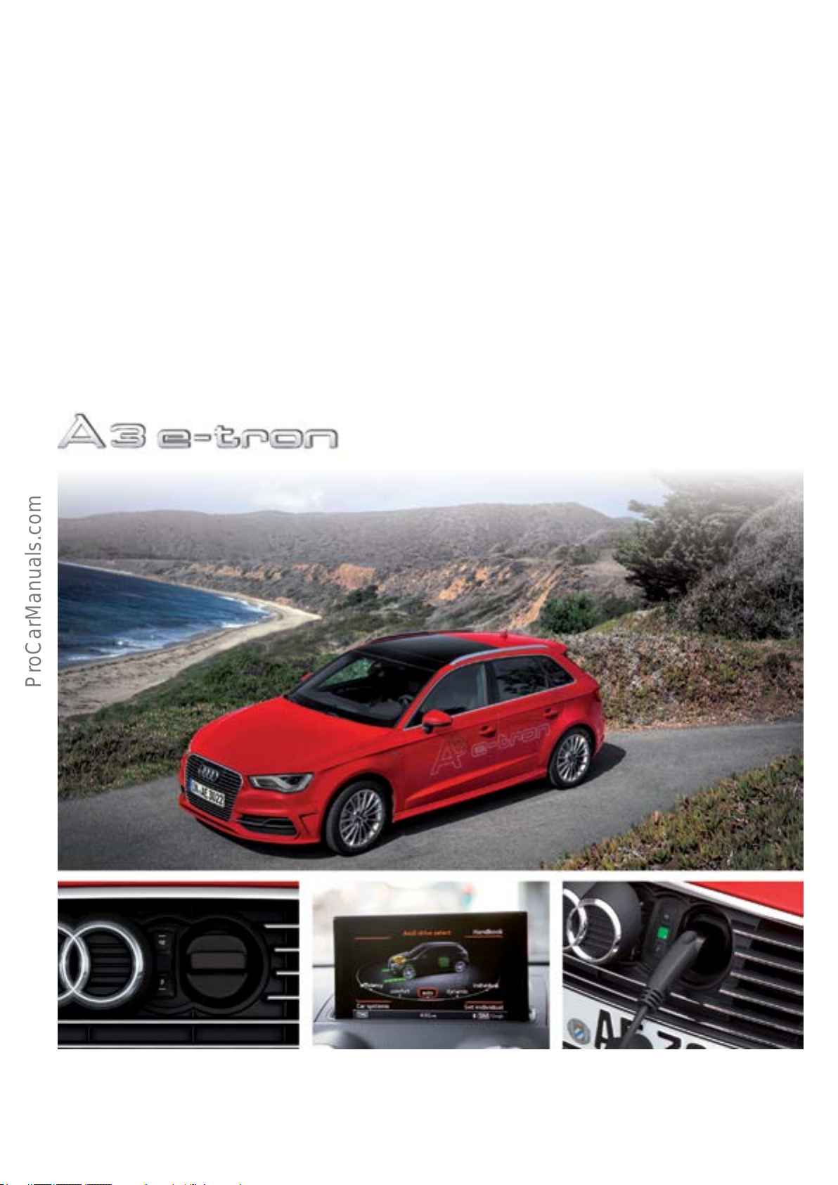
The AudiA3Sportbacke-tron is a plug-in hybrid engineered
to provide a fully integrated e-mobility solution.
There is no need for drivers to change their driving habits
because the Audi A3 Sportback e-tron is designed to allow
simple use of e-mobility.
It has an all-electric driving range of 31 miles (50 km) and
is driven by a 102 hp (75 kW) electric motor with a top
speed of 80 mph (130 km/h). At high speeds and under
heavy acceleration, the internal combustion engine is
automatically activated to provide additional power.
The AudiA3Sportbacke-tron brings together the best of
both worlds - an electric motor for emission-free driving
and an economical internal combustion engine for long
range.
It combines both driving enjoyment and environmental
awareness.
627_042
1
Page 6
Vehicle distinguishing features
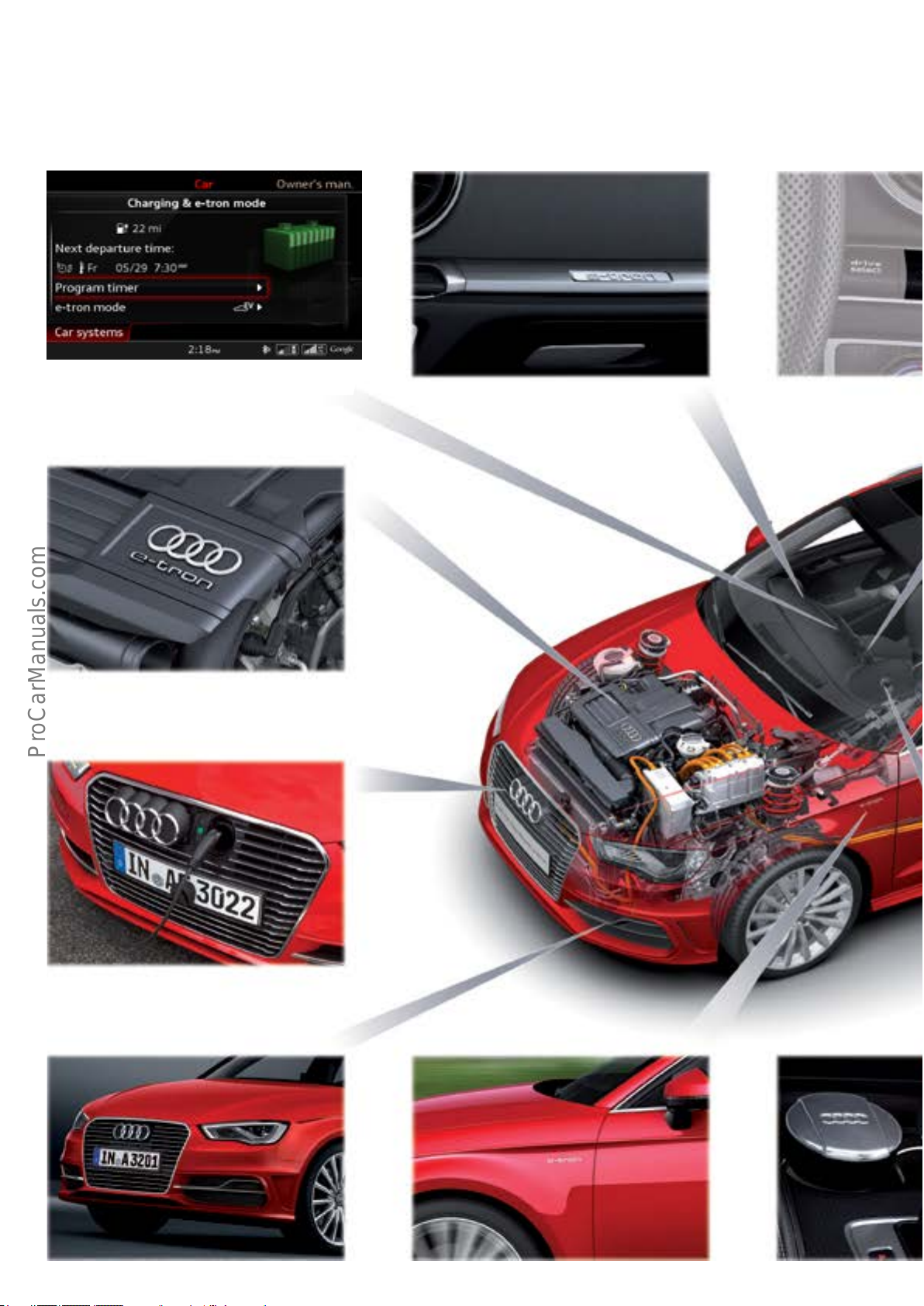
MMI system with e-tron displays
e-tron logo on the design cover in the engine compartment
e-tron logo on the instrument panel (front passenger side)
(European version shown)
Switch for EV mode (E656)
e-tron specic single-frame radiator grille in chrome/
matte black
e-tron specic front bumper with two aluminum-look
surrounds on the air intake covers
e-tron logo on the front fenders
e-tron logo on the selector
lever
2
Page 7
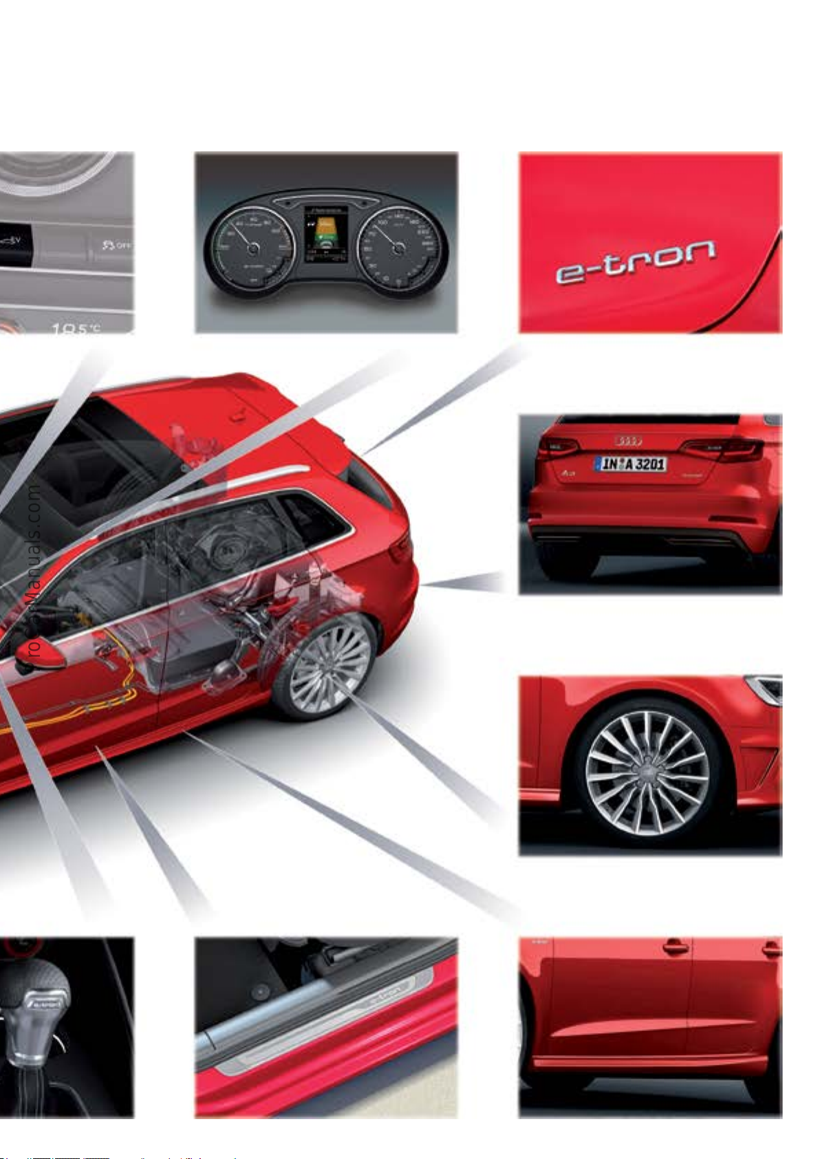
Instrument cluster with power meter and e-tron displays
e-tron logo on the rear deck lid
e-tron specic rear bumper with diusor, aluminum-look
surrounds and concealed exhaust pipes
e-tron logo on the door sills
Various e-tron light alloy wheels available. See the Product
Information Book for complete details.
627_002
S line sills
3
Page 8
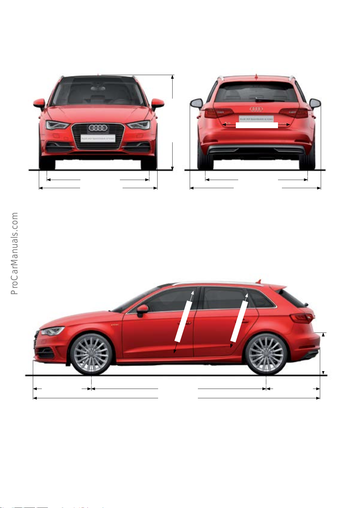
Dimensions
37.5 in (955 mm)
56.06 in (1424 mm)
60.7 in (1542 mm)
70.2 in (1785 mm)
38.8 in (987 mm)
59.6 in (1516 mm)
77.4 in (1966 mm)
627_020
3
37.6 in (957 mm)
26.5 in (675 mm)
34.2 in (871 mm) 31.9 in (811 mm)103.5 in (2630 mm)
169.7 in (4312 mm)
627_021
4
Page 9
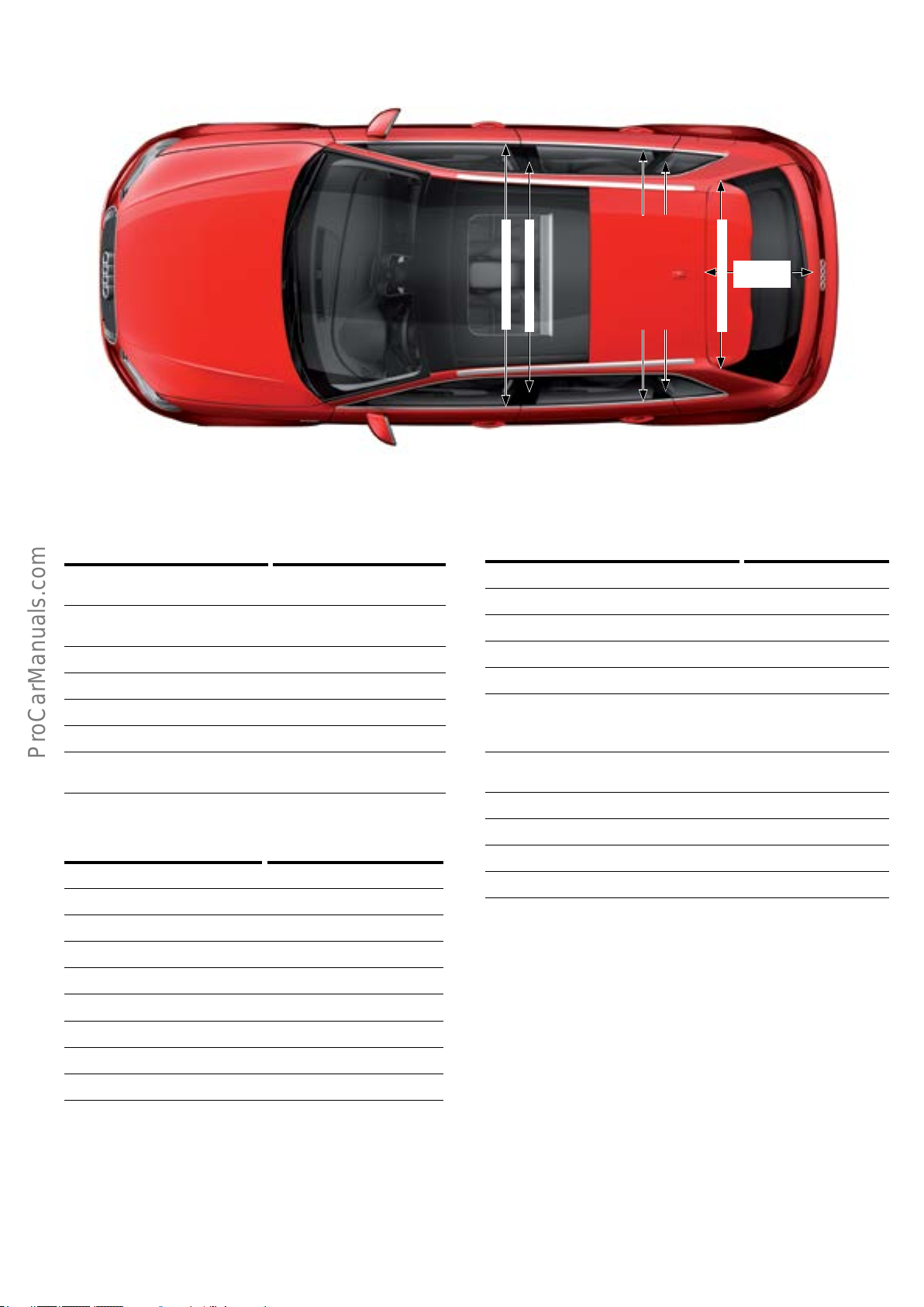
2
1
2
1
30.07 in
(764 mm)
Interior dimensions
Front cabin width 54.8 in(1392 mm)
57.2 in (1453 mm)
Rear cabin width 52.9 in (1344 mm)
55.9 in (1422 mm)
Front headroom 38.8 in (987 mm)
Rear headroom 37.6 in (957 mm)
Through-loading width 39.3 in (1000 mm)
Load sill height 26.5 in (675 mm)
Trunk capacity 13.6 cu ft (385 l)
43 cu ft (1220 l)
57.2 in (1453 mm)
54.8 in (1392 mm)
55.9 in (1422 mm)
52.9 in (1344 mm)
39.3 in (1000 mm)
627_022
Other specications
1)
2)
1)
2)
3)
4)
4)
Concept Plug-in hybrid (PHEV)
Battery type Lithium-ion system
Total capacity in kWh 8.8
Top speed in electric-only mode 80 mph (130km/h)
Top speed 138 mph (222km/h)
Acceleration
4.9 seconds
0 - 37 mph (0 - 60 km/h)
in electric-only mode in s
Acceleration
7.6 seconds
0 –60 mph (0 - 100 km/h)kph
Range (electric drive only) up to 31 m (50 km)
Exterior dimensions and weights
Length 169.7 in (4312 mm)
Width 70.2 in (1785 mm)
Width 77.4 in (1966 mm)
Height 56.06 in (1424 mm)
Front track width 60.7 in (1542 mm)
Rear track width 59.6 in (1516 mm)
Wheelbase 103.5 in (2630 mm)
Curb weight 3395 lb (1540 kg)
Gross vehicle weight 4519 lb (2050 kg)
1)
Shoulder room width
2)
Elbow room width
3)
Maximum headroom
4)
With rear backrest folded down
5)
Excluding mirror
6)
Including mirror
All dimensions are based on the unladen weight of the vehicle.
5)
6)
Total range up to 584 m (940 km)
Drag coecient c
w
0.32
Capacity of fuel tank 10.5 gal (40 l)
5
Page 10

Safety instructions
Electrical safety rules
The following ve safety rules must always be observed
and followed whenever performing work on the high-
voltage system.
This work may only be preformed by qualied High Voltage
Technicians.
1. De-energize the vehicle
The following steps must be taken
by the high voltage Technician.
2. Secure system against re-starting
3. Check that no voltage is present
The following ve high voltage safety rules apply to all high
voltage work in any and all applications. The rst three
apply to high voltage systems in Audi electric vehicles.
These safety rules must be applied in the given order
before beginning work on high voltage systems.
These steps are not relevant to
high voltage vehicles.
Information
Even AC voltages of 25 volts and DC voltages of 60 volts are hazardous to humans. It is, therefore, important to follow the
safety instructions given in ElsaPro and in Guided Fault Finding Test Plans, as well as the warnings displayed on the vehicle.
4. Ground and short-circuit vehicle
5. Coverorblockoadjacentliveparts
Information
Work on the high voltage system may only be performed by a qualied high voltage Technician.
6
Page 11
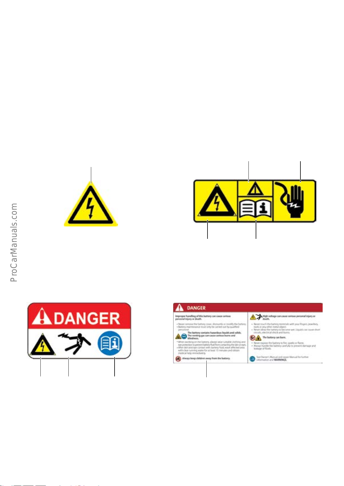
Warning signs
To minimize the risk associated with the high voltage
system for users, service and repair shop personnel, as well
as for technical and medical emergency responders, there
are several warning and information labels attached to the
AudiA3 Sportback e-tron.
The following yellow warning labels are used to identify
high voltage conducting components or high voltage components installed in the immediate vicinity or, for example,
hazardous components concealed by covers.
Warning against hazardous electrical voltage
according to DIN*4844-2 (BGV A8)
Basically, two types of warning label are used:
• Yellow warning label with warning symbol for
electrical voltage.
• Warning label marked "Danger" against a
red background.
Warning against a
hazardous area according
to DIN4844-2 (BGV A8)
Warning against
touching live parts
Warning against
hazardous electrical
voltage according to
DIN4844-2 (BGV A8)
The warning labels marked "Danger" identify high voltage components or high voltage conducting components.
Warning against
hazardous electrical
voltage according to
DIN4844-2 (BGV A8)
Warning against
touching live parts
Mandatory signs:
Observe instructions
for use according to
DIN4844-2 (BGV A8)
Specialhighvoltagebatteryidenticationlabel
This adhesive label is axed to the top of the high voltage
battery, both in English and in the import country's national
language.
Mandatory signs:
Observe instructions
for use according to
DIN4844-2 (BGV A8)
627_005627_004
627_007627_006
*DIN - Deutsches Institut für Normung. A standards dening organization. Similar in function to the SAE.
7
Page 12
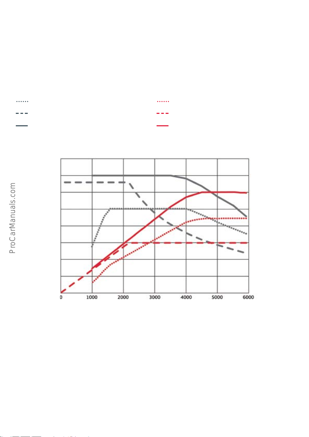
Drive unit
Specications
Torque-power curve
EA211 series 1.4l TFSI engine CUKB
Torque in Nm
Internal combustion engine
Electric motor
System (15seconds)
295.0 lb ft (400 Nm)
258.1 lb ft (350 Nm)
221.21 lb ft (300 Nm)
184.3 lb ft (250 Nm)
147.5 lb ft (200 Nm)
Power in hp
Internal combustion engine
Electric motor
System (15seconds)
268.2 hp (200 kW)
234.6 hp (175 kW)
201.1 hp (150 kW)
167.6 hp (125 kW)
134.1 hp (100 kW)
110.6 lb ft (150 Nm)
73.7 lb ft (100 Nm)
36.8 lb ft (50 Nm)
100.5 hp (75 kW)
67 hp (50 kW)
33.5 hp (25 kW)
Engine speed [rpm]
627_093
8
Page 13
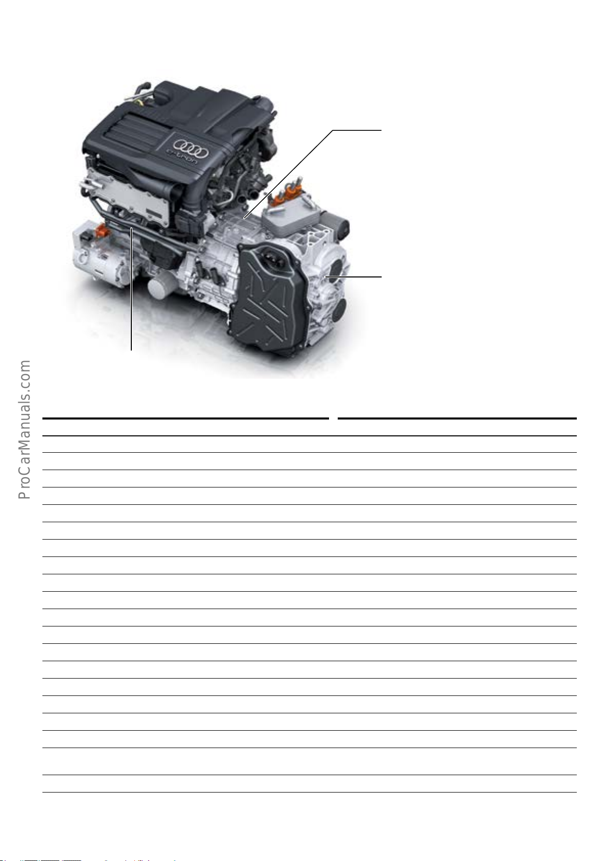
Internal combustion engine and e-machine with transmission
Electro-drive Drive Motor V141
(e-machine)
6-speed dual clutch transmission
(S tronic)
1.4l TFSI engine
Features Specications
Engine code CUKB
Type Four-cylinder in-line engine
Internal combustion engine output 150 hp (110 kW) at 5000 - 6000 rpm
Electric motor output 102 hp (75 kW) at 2000 - 2300 rpm
System output 150 kW
Torque of internal combustion engine 184 lb ft (250 Nm) at 1600 - 3500 rpm
Electric motor torque 243 lb ft (330 Nm) at 2200 rpm
System torque 258 lb ft (350 Nm)
Displacement in cm
3
1395
Stroke 3.1 in (80 mm)
Bore 2.9 in (74.5 mm)
Number of valves per cylinder 4
627_107
Firing order 1–3–4–2
Compression ratio 10:1
Fuel type Premium 91 AKI
Turbocharging Exhaust turbocharger
Engine management system Bosch MED 17.01.21
Powertrain type 6-speed dual clutch transmission (S tronic)
Oxygen sensor control 1 sensor upstream of catalytic converter and 1 sensor down-
stream of catalytic converter
Mixture formation Direct injection
Emission standard SULEV 30
9
Page 14
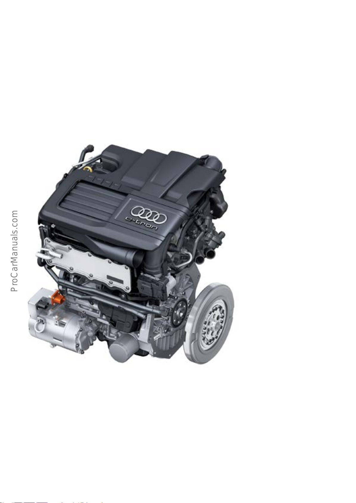
Internal combustion engine
The A3 Sportback e-tron uses the EA211 series 1.4l
engine. Because the transmission is 2.26 in (57.5 mm)
longer to accommodate the e-machine, the engine is
mounted further to the right than in the standard A3
Sportback.
The main bearings, the connecting rod big end bearings
and the piston rings of this engine have special coatings. In
addition, piston backlash has been adapted and the cylin-
der liners are plasma-coated.
The Audi A3 Sportback e-tron can be driven in electric-only
mode. This can result in periods of time during which the
internal combustion engine is not in use.
During electric-only driving, the internal combustion
engine can start in order to heat up the catalytic converter.
To ensure wear-free starting of the internal combustion
engine after electric-only operation, clutch K0 closes and
the e-machine turns the engine over until sucient oil
pressure is obtained.
In the U.S. market, the engine is also equipped with secondary air injection.
Engine start
The internal combustion engine is started by the e-machine.
Unlike the Q5 hybrid quattro, there is no 12V starter motor.
Engine Control Module J623 sends a start message to DSG
Transmission Mechatronic Module J743. Clutch K0 is closed
and connects the e-machine rotor to the internal combus-
tion engine’s crankshaft. The rotor brings the engine’s
crankshaft up to starting speed. J623 then enables the
ignition and fuel injection and the engine starts.
627_023
If it is necessary for the internal combustion engine to start
when the vehicle is running in electric-only mode, the torque
from the e-machine is increased by the amount necessary to
start the internal combustion engine when the clutch closes.
This prevents judder. After starting, clutch K0 is opened and
the internal combustion engine runs at no load. After the
speed of the internal combustion engine has been adapted
to that of the e-machine, clutch K0 is closed again.
10
Page 15
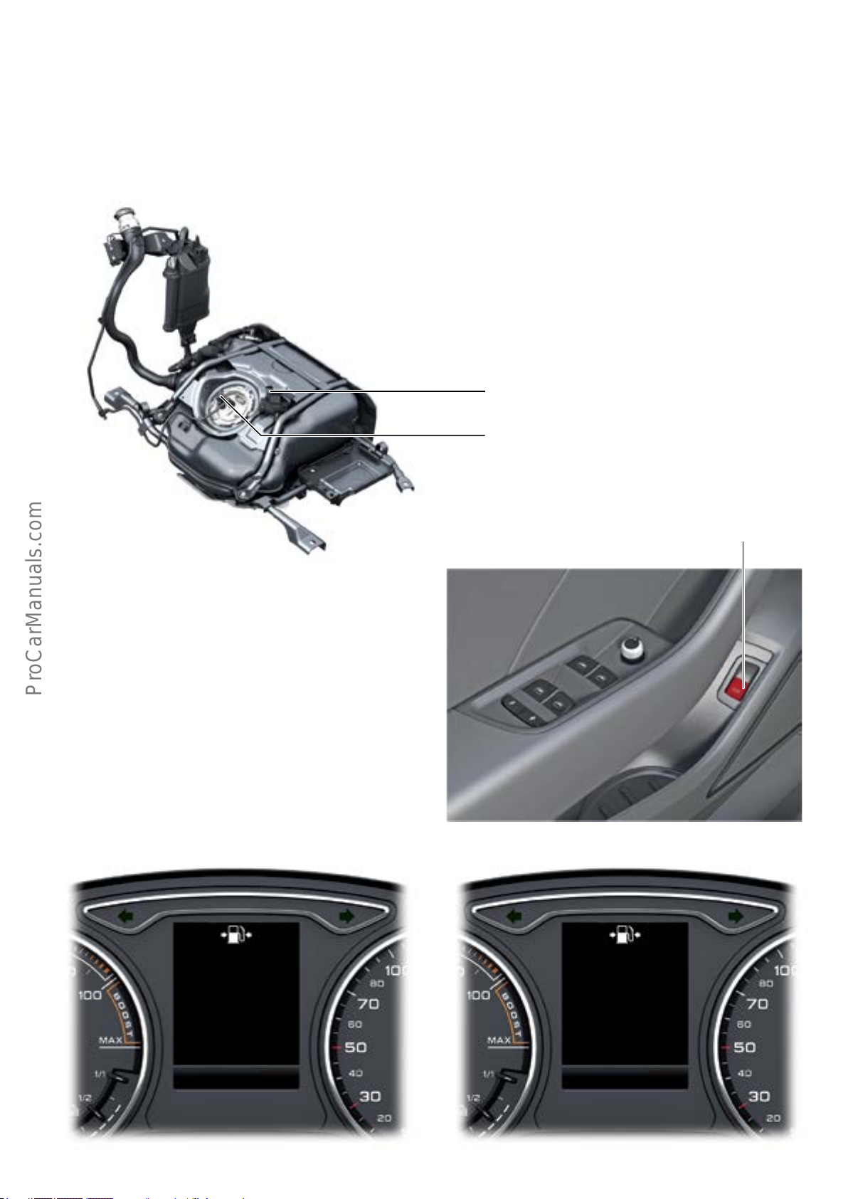
Fuel system
Because hydrocarbons also form when the vehicle is driven in
electric-only mode, there is a danger of overloading the
activated charcoal lter (carbon canister). To prevent this, the
A3 Sportback e-tron is equipped with a pressure reservoir.
During electric-only driving, the line leading to the carbon
canister is closed by Tank Switch-o Valve N288. The pressure in the fuel tank then increases to approximately 4.3
psi (0.3 bar). The pressure is measured by Fuel Tank Pressure Sensor G400 and relayed to the ECM.
Tank Switch-o Valve
N288
Fuel Tank Pressure Sensor
G400
627_094
Fuel ller ap
The fuel ller ap of the A3 Sportback e-tron is locked and
cannot be opened by hand until the pressure in the fuel
tank has dropped. This only takes a few seconds.
When the driver actuates Fuel Filler Door Release Button
E319 on the driver’s door panel, the ECM opens Tank Shuto Valve N288. The reduction in pressure is detected by
Fuel Tank Pressure Sensor G400. Vehicle Electrical System
Control Module 1 J519 then automatically opens the fuel
ller ap.
The status of the fuel ller ap is indicated in the DIS.
Fuel Filler Door Release Button E319
627_095
Tank system:
is being vented.
Please wait
P P
+95
°F +95°F
Tank system:
Now ll tank
627_097627_096
11
Page 16
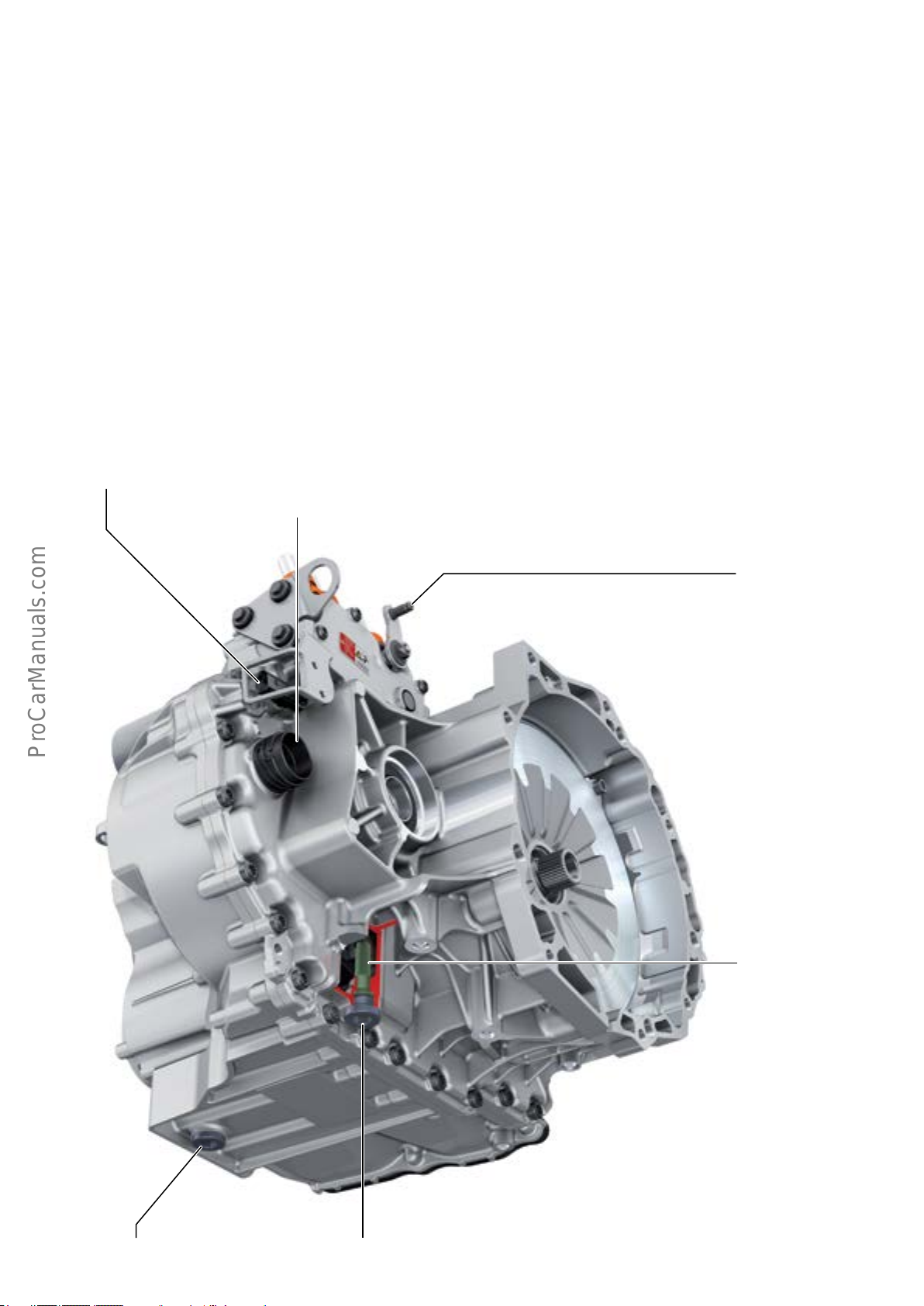
Power transmission
Overview
Power transmission is provided by the front wheel drive,
six-speed 0DD S tronic (DSG) transmission.
The integrated Electro-drive Drive Motor V141 (e-machine)
is a permanently excited synchronous machine that develops up to 102 hp (75 kW) of power. It is capable of delivering approximately 243 lb ft (330 Nm) of torque to the
transmission. V141 provides electric-only drive-away from
standstill and electric-only driving as well as starting the
internal combustion engine via clutch K0. (see page 10).
If necessary, in Boost mode, the (e-machine) and internal
combustion engine are connected via clutch K0 and deliver
the maximum system power to the transmission.
2-pin connector for
safety line
10-pin connector for:
2contacts for Drive Motor Temperature Sensor G712,
6contacts for Drive Motor Rotor Position Sensor 1 G713 and
2contacts for the safety line
In generator mode, V141 is driven by the internal combustion engine using the vehicle’s propulsion energy (recupera-
tion) or through the closed K0 clutch. The electric drive
motor supplies power to the entire vehicle.
Clutches K1 and K2 (see page 16, page 17) transfer
the entire power generated by both drives to sub-gearboxes
1 and 2.
All 3 of clutches K0, K1 and K2 are wet-type clutches and
are controlled by the DSG Transmission Mechatronic
Module J743.
The transmission has only one ATF supply. Approximately
7.3 qt (7 l) of ATF supply both the transmission hydraulics
and the sub-gearbox. Both sub-transmissions form the
manual transmission of the transmission.
Parking lock lever
Oil gauge pipe
627_103
12
ATF inspection boltATF drain plug 1 (manual transmission)
Page 17
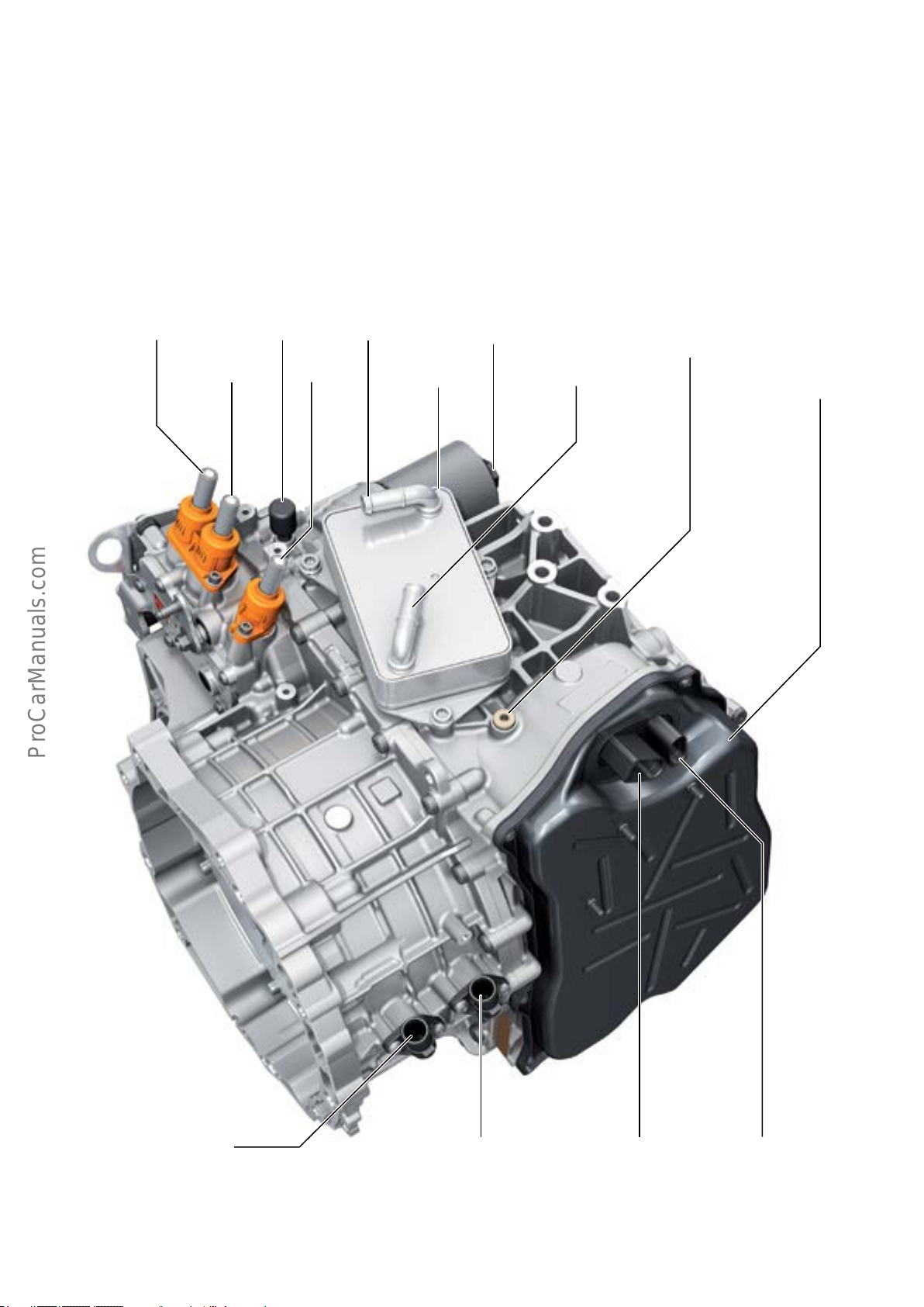
The six forward gears of the transmission provide a ratio
spread of 6.8:1.
The Mechatronic module is located below its housing cover
and is separated from the manual section of the transmission by a bulkhead. During vehicle operation, the Mecha-
tronic module is lled to the overow port by the bulkhead.
(See page 14,15).
The Mechatronic module, clutches, gear selectors and
manual gearbox are supplied on demand by an electrically
driven ATF pump. A hydraulic pressure accumulator serves
as an ATF reservoir.
1)
P6 (W)
P5 (V)
1)
P4 (U)
Coolant supply
1)
ATF cooler Housing cover for
The 0DD transmission is integrated into the vehicle’s
thermal management system. The transmission will also
have a Start/Stop system. DSG Transmission Mechatronic
Module J743 is a participant of the immobilizer system.
ATF pressure lterTransmission vent Plug for the Mechatronic
module ller port
Coolant return
the Mechatronic module
Coolant return line for cooling
V141
Coolant supply for cooling
V141
2-pin connector
for Mechatronic
module power supply
627_104
10-pin connector
(for transmitting data to/
from the Mechatronic
module)
1)
P4 (U), P5 (V), P6 (W) are high voltage lines running from Electric Drive
Power and Control Electronics Module JX1 to Electro-drive Drive Motor V141.
13
Page 18
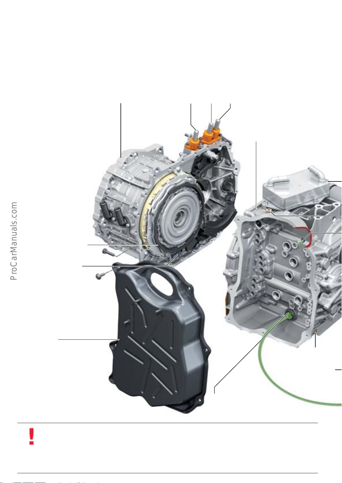
Gearbox modules
The six-speed dual clutch 0DD transmission consists of the
hybrid module, the manual gearboxes and the Mechatronic
module.
Drive Motor Rotor Position Sensor 1 G713 and Drive Motor
Temperature Sensor G712 are located on the hybrid
module. Both supply their data to Electric Drive Power and
Control Electronics Module JX1.
P6 (W)P5 (V)P4 (U)Hybrid module
Manual gearbox
Drive Motor Rotor Position Sensor 1
G713
Drive Motor Temperature Sensor
G712
Housing cover for
Mechatronic module
ATF drain bolt 2
(Mechatronic module)
Hydraulic Pump Motor
V401 with rotor position
sensor
From ATF intake lter,
located in sump of manual
gearbox
14
Information
Before removing the transmission or the Mechatronic module, it must be ensured that the ATF pressure accumulator is
de-pressurized and that the hydraulic pump is disabled by running the relevant ODIS Service Test Plan. If the ATF, the trans-
mission or the Mechatronic module is replaced, check that the ATF level has been set correctly, as detailed in ElsaPro, and
that the Mechatronic module is lled with ATF before starting the engine. This prevents the high-pressure pump from
running dry. The Mechatronic module and the immobilizer must be adapted using the relevant ODIS Service Test Plan for
replacing the Mechatronic module.
Page 19
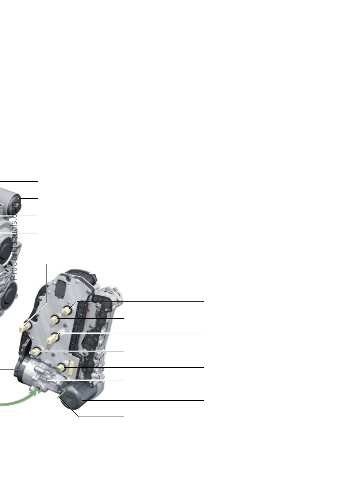
DSG Transmission Mechatronic J743
Apart from the gear selector and clutch slave cylinder, the
Mechatronic module houses all sensors and actuators of
the transmission control module. This includes the valves,
pump motor, pressure and temperatures sensors and the
distance and speed sensors.
Main pressure valve and pressure relief valves
• Main Pressure Valve N472 (accumulator lling valve, allows
controlled evacuation of the pressure accumulator).
• Automatic Transmission Pressure Regulating Valve 3 N217
(pressure relief valve, sub-gearbox 1).
• Automatic Transmission Pressure Regulating Valve 4 N218
(pressure relief valve 2, sub-gearbox 2).
ATF cooler
ATF pressure lter
During operation, the Mechatronic module is lled to the
ATF overow port. This oil volume does not drain o during
maintenance via ATF drain plug 1. ATF drain plug 2 must be
removed for this purpose.
Clutch valve
• Automatic Transmission Pressure Regulating Valve 1 N215
(pressure control valve of clutch K1, sub-gearbox 1).
• Automatic Transmission Pressure Regulating Valve 2 N216
(pressure control valve of clutch K2, sub-gearbox 2).
• Decoupler Valve N689
(clutch pressure control valve K0).
Cooling oil valve
• Cooling Oil Valve N471 (controls clutch cooling).
Gear selector valves
• Sub-transmission 1 Valve 1 N433 (controls the 1-N gear selector).
• Sub-transmission 1 Valve 2 N434 (controls the 5-3 gear selector).
• Sub-transmission 2 Valve 1 N437 (controls the 4-R gear selector).
• Sub-transmission 2 Valve 2 N438 (controls the 6-2 gear selector).
Plug for Mechatronic module ller port
ATF overow port
Transmission Input Speed Sensor 1
G632
(output shaft for sub-gearbox 1)
Pressure and temperature sensor
• Transmission Hydraulic Pressure Sensor G270
• Clutch Pedal Position Sensor 1 G617
• Clutch Pedal Position Sensor 2 G618
J743
Gear Position Distance Sensor 4
G490
(4-R, sub-gearbox 2)
Gear Position Distance Sensor 3
G489
(5-3, sub-gearbox 1)
ATF hydraulic pump
• Temperature Sensor in Control Module G510.
(measures pressure in ATF hydraulic pressure accumulator).
(measures pressure in piston of clutch K1).
(measures pressure in piston of clutch K2).
Gear Position Distance Sensor 1
G487
(1-N, sub-gearbox 1)
Transmission input speed sender 2
G612
(output shaft for sub-gearbox 2)
Gear Position Distance Sensor 2
G488
(6-2, sub-gearbox 2)
Intake manifold for
low-pressure pump
Intake port for high-pressure pump
The ATF hydraulic pump is a tandem pump. It consists of
a low-pressure pump and a high-pressure pump. The
low-pressure pump delivers, through the ATF intake lter,
a large volume of ATF for cooling the clutch and lubricating all components.
ATF hydraulic uid reservoir
627_105
The high-pressure pump serves to activate the clutch and
the gear selectors. It draws in ATF from the ooded Mecha-
tronic area through a port. To ensure that this area is kept
ooded, a portion of the ATF ows from the low-pressure
pump into the Mechatronic area.
15
Page 20
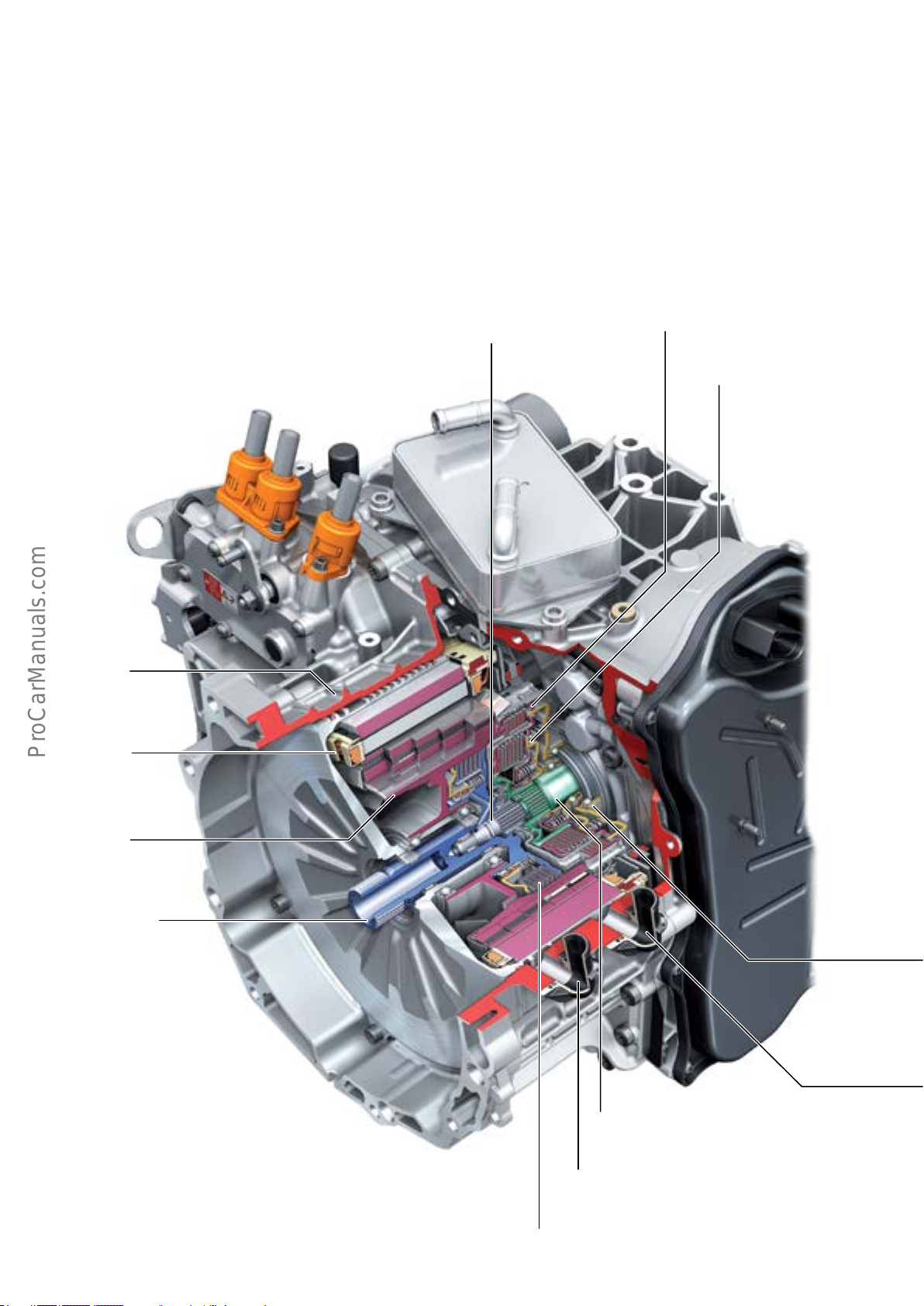
Hybrid module
The hybrid module consists of Electro-drive Drive Motor
V141 (which is encapsulated by a cooling jacket), clutches
K1 and K2 for sub-gearboxes 1 and 2 plus clutch K0.
Clutch K0 is located on the secondary side of the dual mass
ywheel and connects the e-machine to the internal com-
bustion engine. The clutch is activated and cooled through
the hollow-drilled input shaft of sub-gearbox 1 by means of
rotary feed-throughs.
Input shaft for
sub-gearbox 1
Clutch K1
Clutch K2
Cooling jacket
Electric drive
motor:
stator
Electric drive
motor:
rotor
Transmission input
shaft
16
Input shaft for sub-gearbox 2
627_106
Coolant return line for cooling
V141
Clutch K0
Page 21
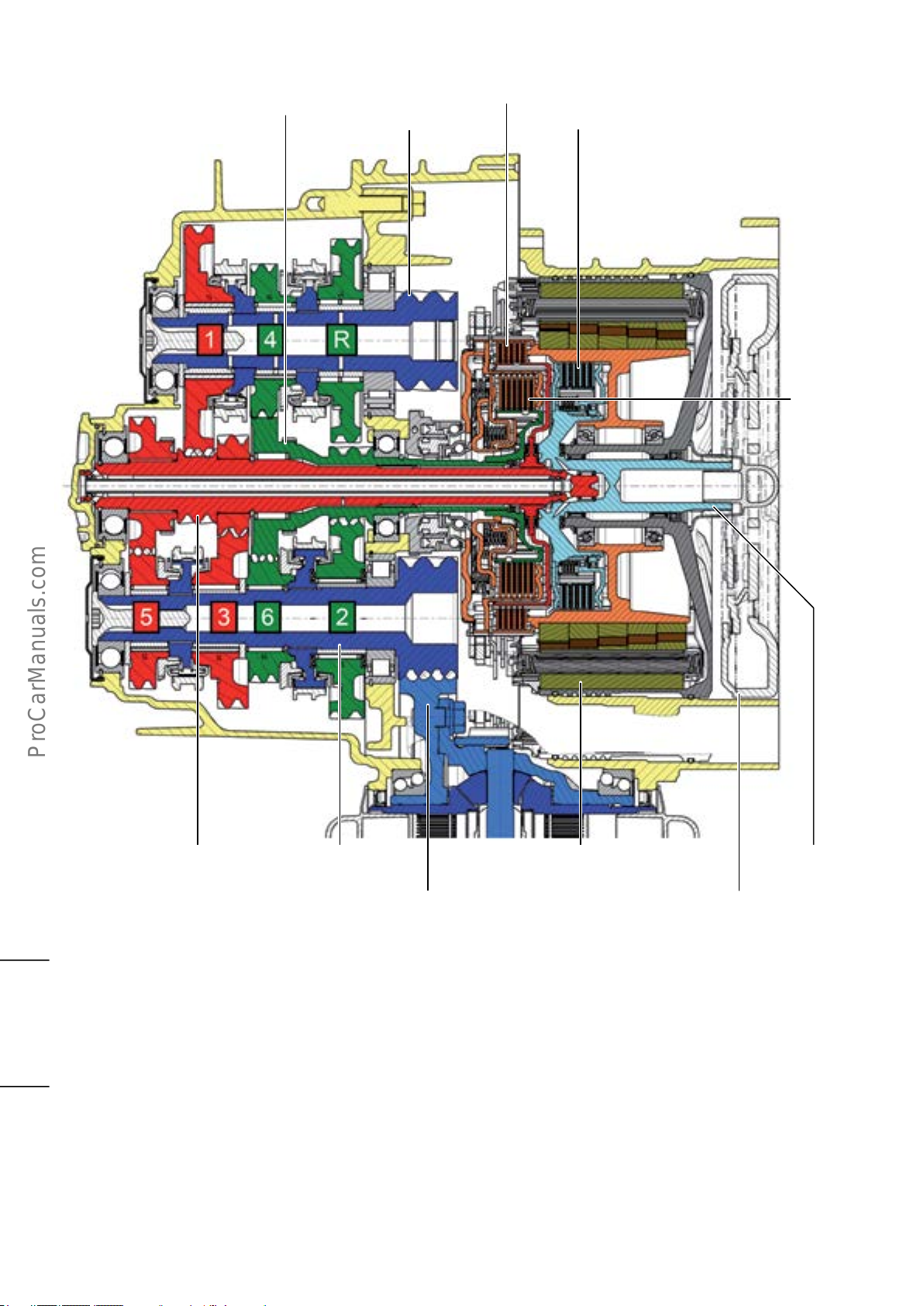
Manual gearbox
Input shaft for
sub-gearbox 2
Clutch K1
Clutch K0Output shaft 1
Clutch K2
Input shaft for
sub-gearbox 1
2 concentric clutch slave cylinders actuate the engagement bearings
of clutches K1 and K2. Due to the engagement bearings, the clutch
slave cylinders no longer have to rotate. This means there are no feed
throughs that cause unwanted friction loss and leakage.
Coolant return line for cooling
V141
Output shaft 2 Electro-drive Drive Motor
Front axle dierential spur gear
627_111
V141
Dual mass ywheel
Transmission input
shaft
Clutch K1 transmits the engine torque to sub-gearbox 1.
The uneven gears (1, 3 and 5) are engaged in sub-gearbox 1.
Clutch K2 transmits the engine torque to sub-gearbox 2, in
which the even gears (2, 4 and 6) and reverse gear are
engaged.
The reverse gear pinion meshes with the 2nd gear pinion.
The reverse gear is engaged by power transmission to
output shaft 1 through clutch K2, input shaft 2, the
engaged 2nd gear pinion and the engaged reverse gear
pinion.
Both output shafts mesh with the spur gear of the front
axle drive.
17
Page 22
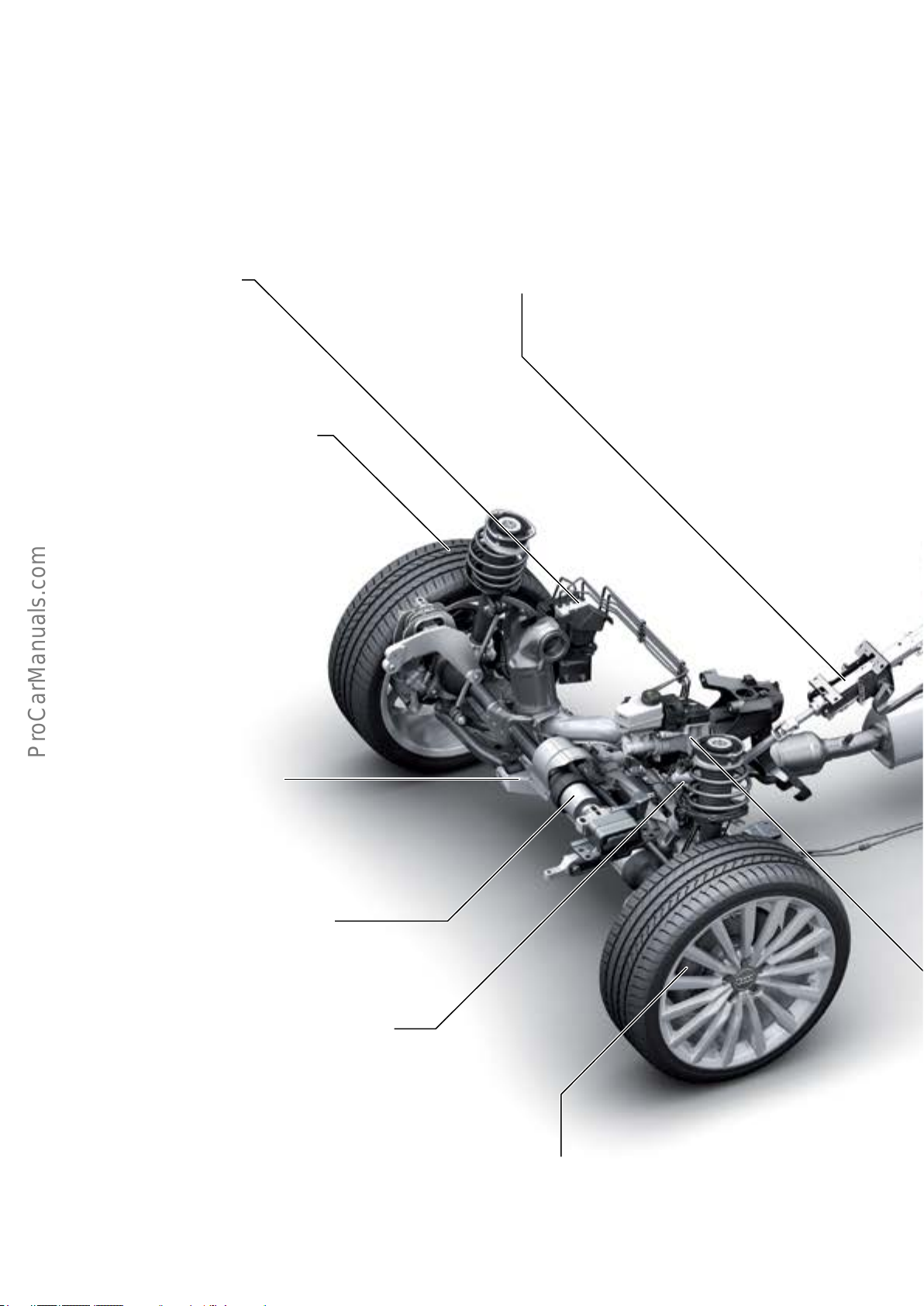
Suspension
Overview
The suspension system of the AudiA3Sportbacke-tron is
based on the suspension system of the conventionalengined AudiA3Sportback.
ABS/ESC module
Continental MK100
• Carry-over from AudiA3Sportback
Wheels/tires
• Exclusive wheel design (17“ and 18“)
• Use of low rolling resistance tires (17" only)
Manuallyadjustablesteeringcolumn
• Carry-over from Audi A3 Sportback
MacPherson front suspension
• Carry-over from AudiA3Sportback
• Modied damper setup
Electro-mechanical steering
• Carry-over from AudiA3Sportback
Brake system pressure accumulator
• New concept and design
Front wheel brakes
• 16“ brake system
• Brake caliper TRW PC 57-25/14
• Brake disc diameter: 12.2 in (312 mm)
18
Page 23
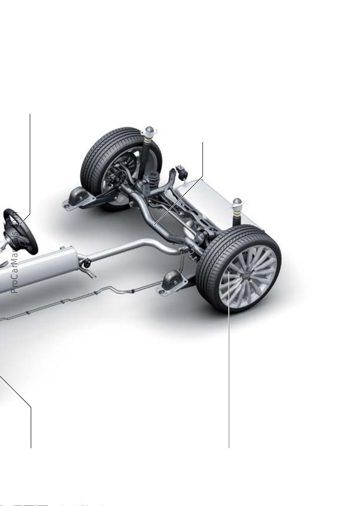
Multi-function steering wheel
• Carry-over from AudiA3Sportback
Four-link rear suspension
• Carry-over from AudiA3Sportback
• Modied damper setup
• Modied anti-roll bar based on higher axle load due to high
voltage battery weight
• Partial modication of engine/transmission mounts due to
modied exhaust system
Electro-mechanical brake servo
• First use in an Audi model
627_098
Rear wheel brakes
• 15“ brake system
• Brake caliper Continental FNC-M38
• Brake disc diameter: 10.7 in (272 mm)
19
Page 24
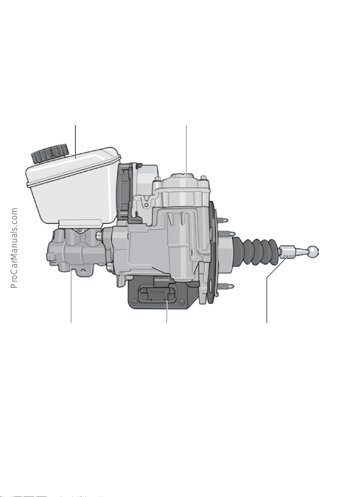
Electro-mechanical brake servo
Because intake manifold vacuum isn’t available when
driving in electric only mode, a new brake booster system
was developed. The use of the electro-mechanical brake
servo eliminates the need for an additional vacuum pump
normally used in conjunction with a conventional pneumatic brake servo.
Brake uid reservoir Motor/gear assembly
The electro-mechanical brake servo oers the following key
advantages over a conventional pneumatic brake servo:
• Vacuum-independent brake servo.
• High pressure generation dynamics.
• High pressure regulation accuracy.
• Constant brake pedal characteristic/pedal force.
Tandem master brake cylinder
Brake Booster Control Module
J539
627_099
Push rod
(brake pedal connection)
20
Page 25
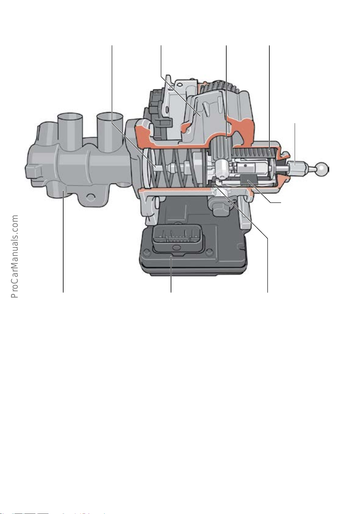
Design and functional principle
Upper pinion shaft
Booster sleeveMotor/gear assemblyPiston rod
Push rod
(brake pedal connection)
Brake Pedal Position Sensor
G100
Tandem master brake cylinder Lower pinion shaft
The brake pressure applied by the driver is boosted by the
Motor/gear assembly. An AC motor drives two pinion shafts
through a reduction ratio. The splines of the pinion shafts
are in mesh with the spline on the booster sleeve. The
rotary motion of the pinion shafts is translated into a
longitudinal motion of the booster sleeve. To increase the
brake pressure, the booster sleeve is moved towards the
tandem master brake cylinder (to the left in the diagram).
After a dened amount of the idle travel (play), the booster
sleeve comes into contact with the push rod and, if the
electric motor is further activated, exerts force upon the
push rod (in addition to the brake pressure applied by the
driver). The electric motor is activated by Brake Booster
Control Module J539. The control module receives information on the position of the brake pedal and the push rod
(= driver input) from integrated Brake Pedal Position Sensor
G100.
627_100
Brake Booster Control Module
J539
The position of the electric motor rotor and, indirectly, the
position of the booster sleeve is monitored by a rotor posi-
tion sensor (Hall sender) in the electric motor.
The sliding assembly of the booster sleeve on the push rod,
and the resultant separation of both components, ensures
that the driver can apply brake pressure even if the boost
function fails.
J539 provides for terminal 15 after-run when the ignition is
switched o. If the vehicle is stationary and the driver is
not applying the service brake, the run-on time is approxi-
mately 1 minute.
If the vehicle is actively braked by the driver after the igni-
tion is switched o, brake boost is maintained for up to
approximately six minutes. After approximately three
minutes and after approximately six minutes, the driver is
instructed to secure the vehicle against rolling and
informed that brake boost will be deactivated.
The signals from Brake Pedal Position Sensor G100 of the
electro-mechanical brake servo are used for activating the
brake light.
21
Page 26
Brake System Pressure Reservoir VX70
If required, the e-machine is used as a generator in overrun mode to recharge the high voltage battery (recuperation). The electric motor is “driven”. It creates drag and
generates additional braking torque at the driven wheels.
Because this process would be independent of driver
inputs, it would be more dicult for the driver to perform
anticipatory braking. This is why it is important that a
braking torque dened by the driver be available at any
time and that the driver be able to gauge the eect of this
torque.
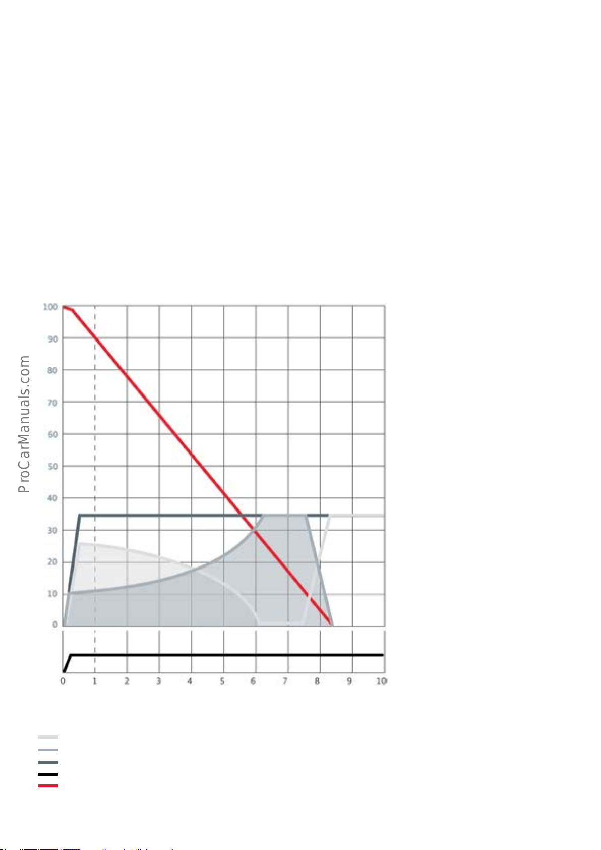
Example of "Blended Braking"
Hydraulic brake pressure is reduced during recuperation.
This reduction is made in an eort to match the total
amount of “hydraulic” braking and “electrical” braking to
the actual driver input. Brake System Pressure Reservoir
VX70 is used to achieve the desired eect.
The combination of “hydraulic” braking and “electrical”
braking is referred to as “blended braking.” As an example,
the deceleration at a specic point in time (one second
after the start of braking) is specially marked in the
diagram. The amount of deceleration ‘a’, which the driver
wishes to achieve, is provided by the total deceleration
resulting from hydraulic braking torque ‘a’ plus the deceleration resulting from generator braking torque ‘a’.
a
. a=aH+a
G
G
Speed [kph] Deceleration [%g]
Key:
Deceleration resulting from "hydraulic" braking torque a
Deceleration resulting from generator braking torque (recuperation) of AC drive a
Requested deceleration through brake pedal actuation by driver a
Pedal travel
Vehicle speed
a
a
H
a
G
Time [s]
H
627_101
G
22
Page 27
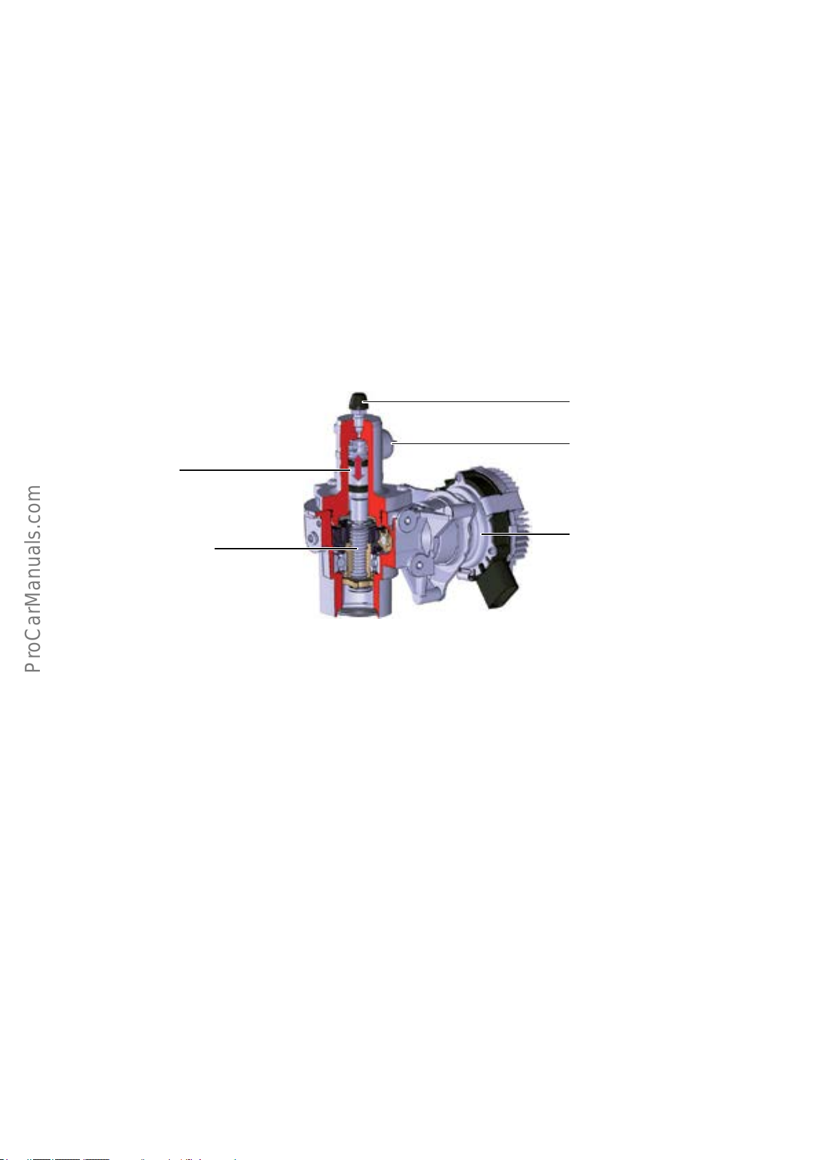
Design and functional principle
Brake System Pressure Reservoir VX70 is connected directly
to the brake master cylinder.
If the brake pressure applied by the driver (dependent on
the additional braking torque of the e-machine during
recuperation) has to be reduced, the electric motor of the
pressure reservoir is activated by the Brake Booster Control
Module J539. The piston performs a lift motion due to the
spindle drive in the cylinder, cylinder volume increases and
brake uid is taken in from the braking circuit. The braking
pressure within the system decreases. At the same time,
the brake boost provided by the electro-mechanical brake
servo is reduced to ensure that the brake pedal does not
"give".
Piston
Spindle drive
If the additional braking torque of the e-machine decreases
again during active braking, or if the generator mode of the
electric drive is fully deactivated, the previously reduced
braking pressure must be increased again. J539 re-activates
the electric motor of the pressure reservoir. The piston
movement reduces the cylinder volume and the brake uid
in the cylinder is returned to the braking circuit. The pressure within the braking system increases accordingly.
Bleeder valve
Connection to braking circuit
Electric motor
Service
The electro-mechanical brake servo - including Brake Servo
Control Module J539 and Brake System Pressure Reservoir
VX70 - are accessed through Address Word 23 in ODIS
Service. It can only be replaced as a complete assembly.
After replacement, the control module must be encoded.
It is important to bleed the brake system properly before
encoding. This is done through a Basic Setting Test Plan
which congures the system to acquire measured data
from the corresponding sensors when the brake pedal is at
rest (released) and when it is depressed.
627_102
In addition, brake pressure is developed by activating the
electric motor, and a pressure-volume curve is obtained.
Component tolerances are recognized and factored in
during subsequent control operations.
It is also necessary to perform the Basic Setting procedure for
the pressure reservoir. Both basic setting procedures must
also be carried out after replacing the pressure reservoir.
Actuator diagnosis Test Plans have been implemented for
function-testing the electro-mechanical brake servo and
pressure reservoir.
23
Page 28
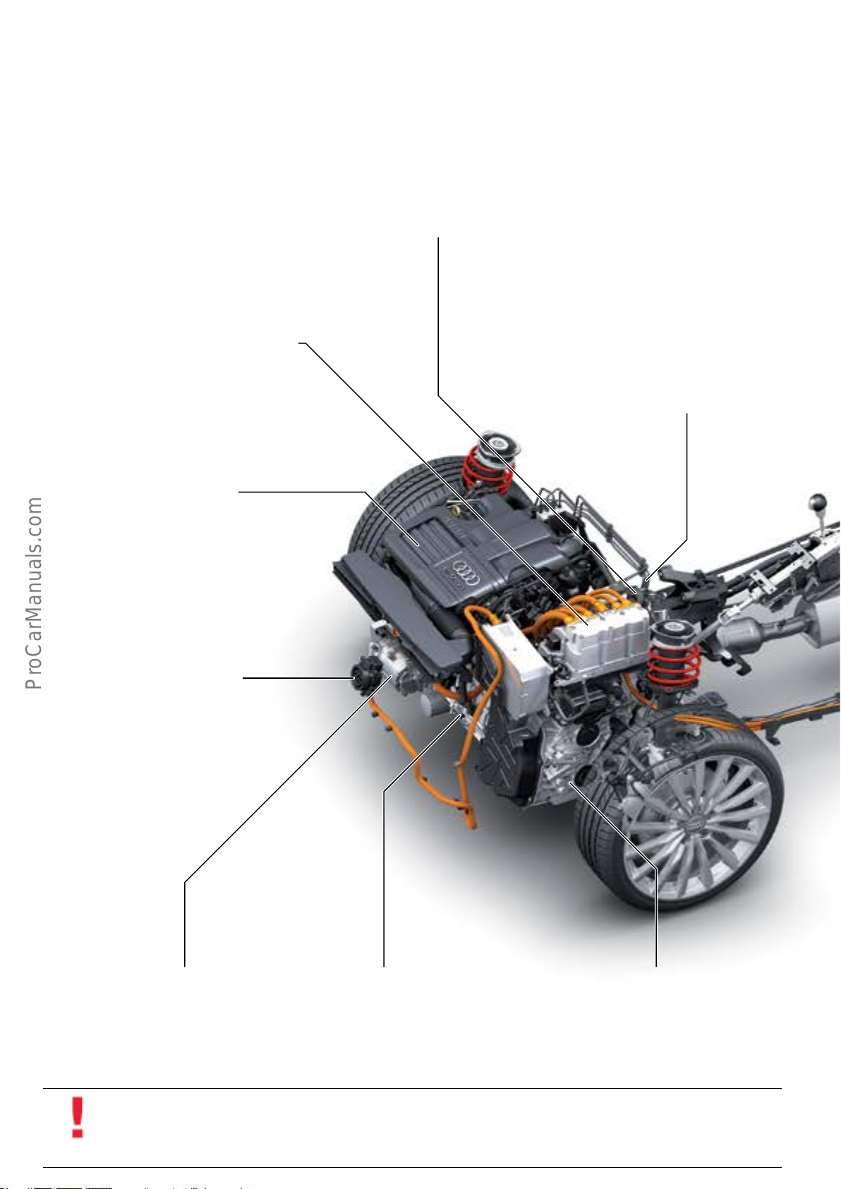
High voltage battery
Overview of hybrid components
The following high voltage components are installed in the
Audi A3 Sportback e-tron:
Power electronics
It converts the direct current stored in the high
voltage battery to alternating current for the
e-machine. The power electronics are cooled by the
low-temperature cooling circuit 2.
Engine
Four cylinder engine with turbocharger :
• 1.4l TFSI 147 hp (110 kW)
Electrical brake servo
The dependencies governing the utilization of braking torque
lead to electrical deceleration uctuations which have to be
compensated hydraulically in accordance with the driver's
wishes. The main focal points during the development of the
electrical brake servo were fully utilizing the deceleration potential of the e-machine under driver initiated braking and extending the electric driving range of the e-machine.
PTC heater
High Voltage Heater (PTC) Z115 is connected to High
Voltage Battery Charger 1 AX4 by a high voltage wire.
It heats the coolant for the passenger compartment heat
exchanger during electric driving and is also integrated in
the stationary air conditioning function.
Charging port
The all-purpose charging cable can be
used to charge the high voltage battery
at both household outlets and commercial outlets using an interchange-
able connecting plug (120 V AC and
240 V AC).
Electric AC compressor
The electric AC compressor is integrated into the high
voltage system and cools both the passenger compart-
ment and Hybrid Battery Unit AX1 as required.
e-machine (Electro-drive Drive Motor V141)
The e-machine is connected to the transmission via
clutchK0. It is able to generate a braking torque at
the wheel in dependence on RPM, battery temperature
and state of charge.
6-speed dual clutch transmission
Stronic
Consists of 2 sub-gearboxes engaged by
multi-plate clutches K1 and K2. It is
possible to select between 3 drive programs using the selector lever.
24
Information
All high voltage components are connected to the vehicle chassis via equipotential bonding.
The equipotential bonding is a low-resistance wire or bolted connection, connecting the high voltage components to the
vehicle chassis.
Page 29
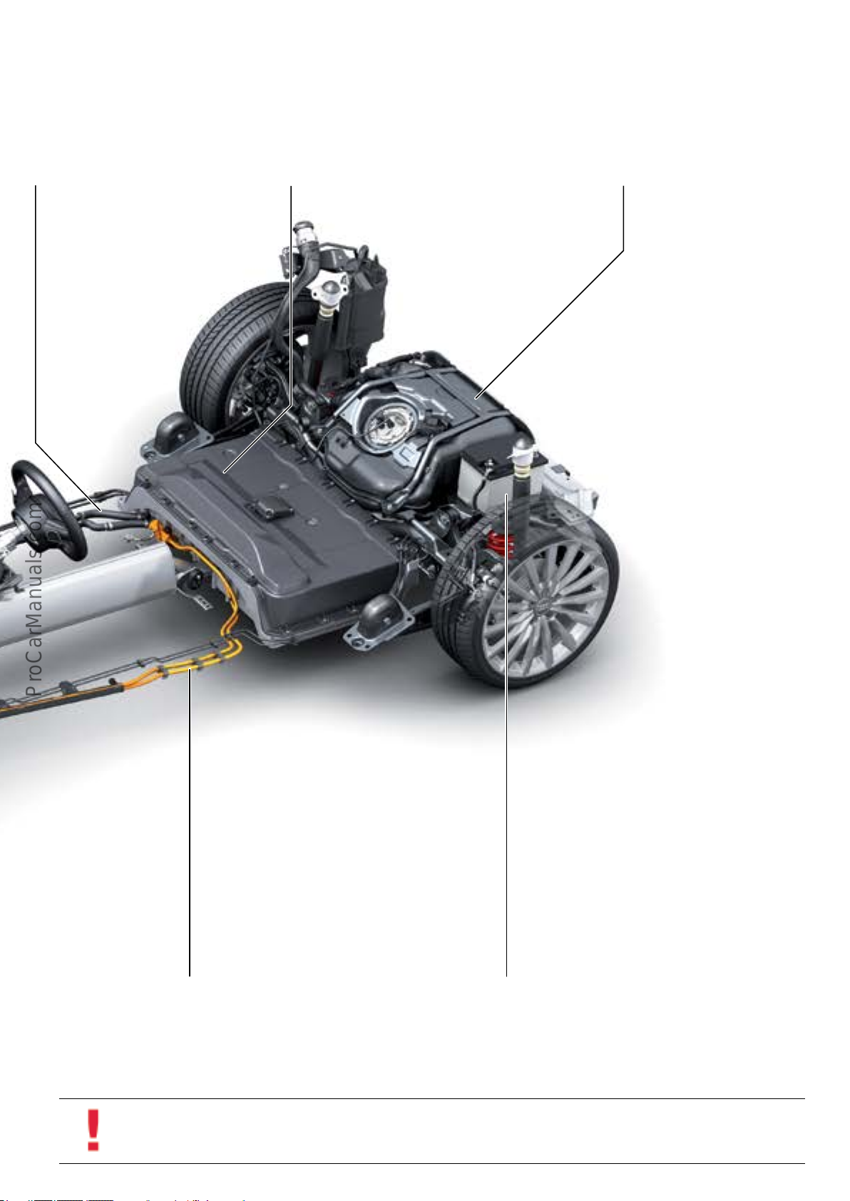
Battery cooling system
The battery cooling system is integrated into
the low-temperature cooling circuit 2.
High voltage battery module
The high voltage battery module consists of 8 modules each
with 12 prismatic cells. The voltage is between 280 and 390 V,
depending on state of charge.
Fuel tank
The fuel tank has a capacity of 10.5 gal
(40 l) and is installed over the rear axle.
High voltage lines
All high voltage lines are double-insulated and color-coded
orange for easy recognition. To avoid incorrect assembly, the
high voltage lines are mechanically coded and identied by a
colored ring below the bayonet ring.
627_003
12 volt vehicle battery
Installed over the rear axle, it is responsible for supplying
power to the low-voltage components.
Information
Always follow the directions in the electronic repair information when performing work on equipotential bondings.
25
Page 30
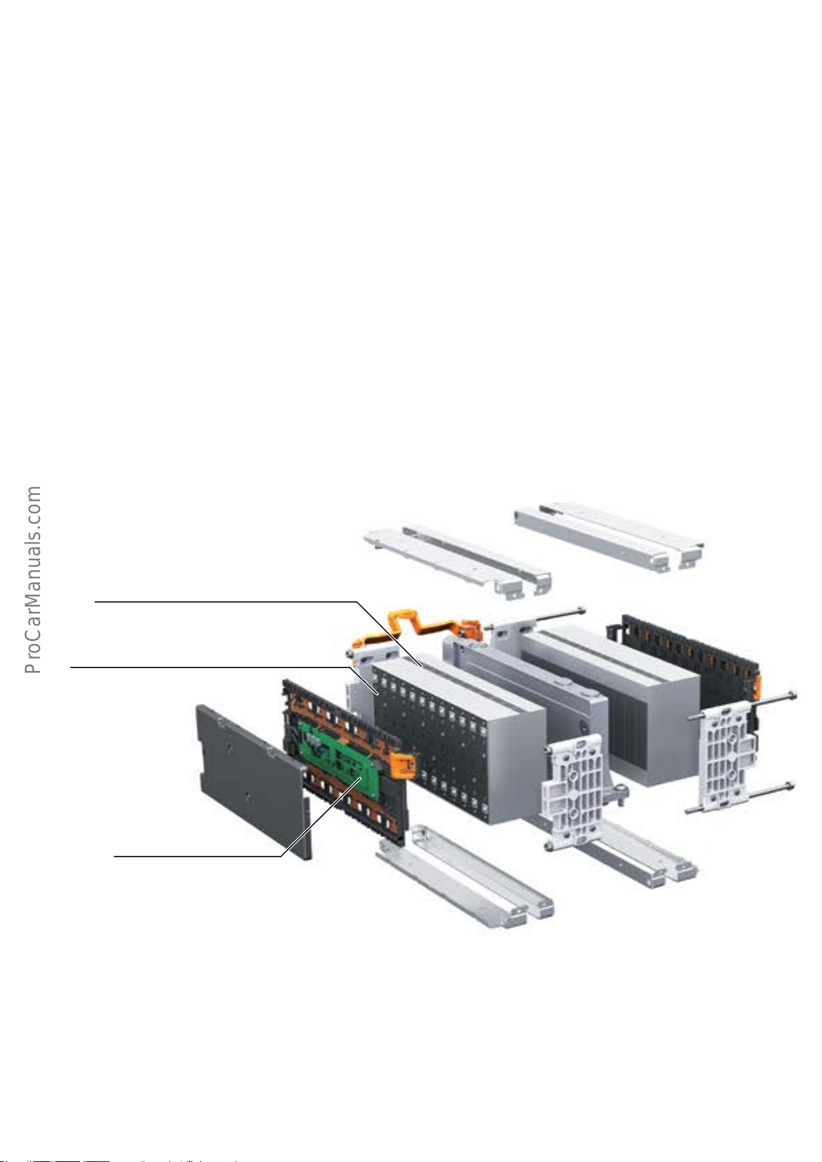
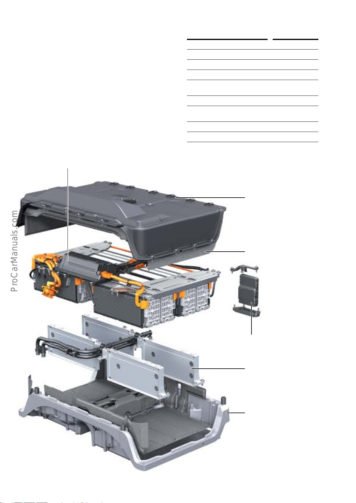
Hybrid Battery Unit AX1
Hybrid Battery Unit AX1 is mounted on the underside of the
vehicle and has the following components:
• Battery Regulation Control Module J840.
• High voltage Battery Switch Box SX6.
• 8 cell modules each with 12 battery cells and controller.
• Battery cell cooling system.
• Connections for the high voltage wiring harness.
• Connections for the 12 volt electrical system.
• Coolant connections.
The bottom section of Hybrid Battery Unit AX1 housing is
made from cast aluminum and the top section from
polymer. The sections are bolted and bonded forming and
airtight housing.
Pressure changes inside the housing caused by temperature
variation are equalized by the pressure equalization ele-
ments. If the pressure inside AX1 is too high, the pressure
relief valve opens.
The pressure equalization elements and the pressure relief
valve are installed under a cover on the top side of AX1.
Hybrid Battery Unit AX1 is attached to the vehicle chassis
by an equipotential bond.
Cell
module
Cell
Cell controller
26
Page 31
Specications
Two cell modules are bolted to a cooling element on the
underside. The four cooling elements are connected to AX1
in parallel. The inlet and outlet temperature sensors are
integrated into the coolant connections.
High voltage Battery Switch Box SX6
Rated voltage 352
Cell voltage 3.7
Number of cells 96
Capacitance in Ah 25
Operating temperature -18 to 140 °F
(-28 to 60 °C)
1)
Energy content in kWh 8.8
Usable energy content in
7.0
2)
kWh
Power in kW Maximum 90
Weight 264 lb (120 kg)
1)
The charging/discharging currents are reduced at temperatures of 122 °F
(50 °C) and higher.
2)
The state of charge is maintained at between 25% and 85%.
Housing upper shell
(polymer)
Insulation
Battery Regulation Control Module
J840
Heat sink of Hybrid Battery Unit
AX1
Housing upper shell
(aluminium casting)
627_036
27
Page 32
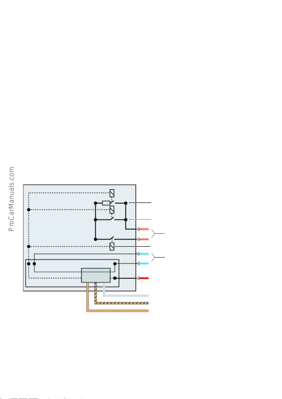
High voltage contacts
There are three high voltage contacts (referred to as contactors) in Hybrid Battery Unit AX1. A contactor can be
compared to a relay but is designed to carry higher electrical loads.
When terminal 15 is switched on, Battery Regulation
Control Module J840 closes the negative high voltage
contacts and the pre-charging contact. A small amount of
current ows through the resistor which charges Interme-
diate Circuit Capacitor 1 C25 in Electric Drive Power and
If these high voltage contacts are closed, AX1 is connected
to the other high voltage components and current is able to
Control Electronics JX1. The positive high voltage contact is
not closed by J840 until the C25 is fully charged.
ow. Contactors for both the positive and negative side are
installed. A 10 ohm resistor is integrated in the second
positive high voltage contact. This is referred to as the
pre-charging contact.
The high voltage contacts are opened by Battery Regulation Control
Module J840 if:
• Terminal 15 is switched “o “,
• Or the safety line is disconnected,
• Or a crash signal from Airbag Control Module J234 is detected,
• Or the 12-volt power supply for Battery Regulation Control
Module J840 is interrupted.
TW
J840
Pre-charging contact
High voltage contact (+)
352 V
High voltage contact (-)
Safety line
Terminal 15
Discrete line
Powertrain CAN bus
Hybrid CAN bus
28
615_015a
Page 33

Notes
29
Page 34
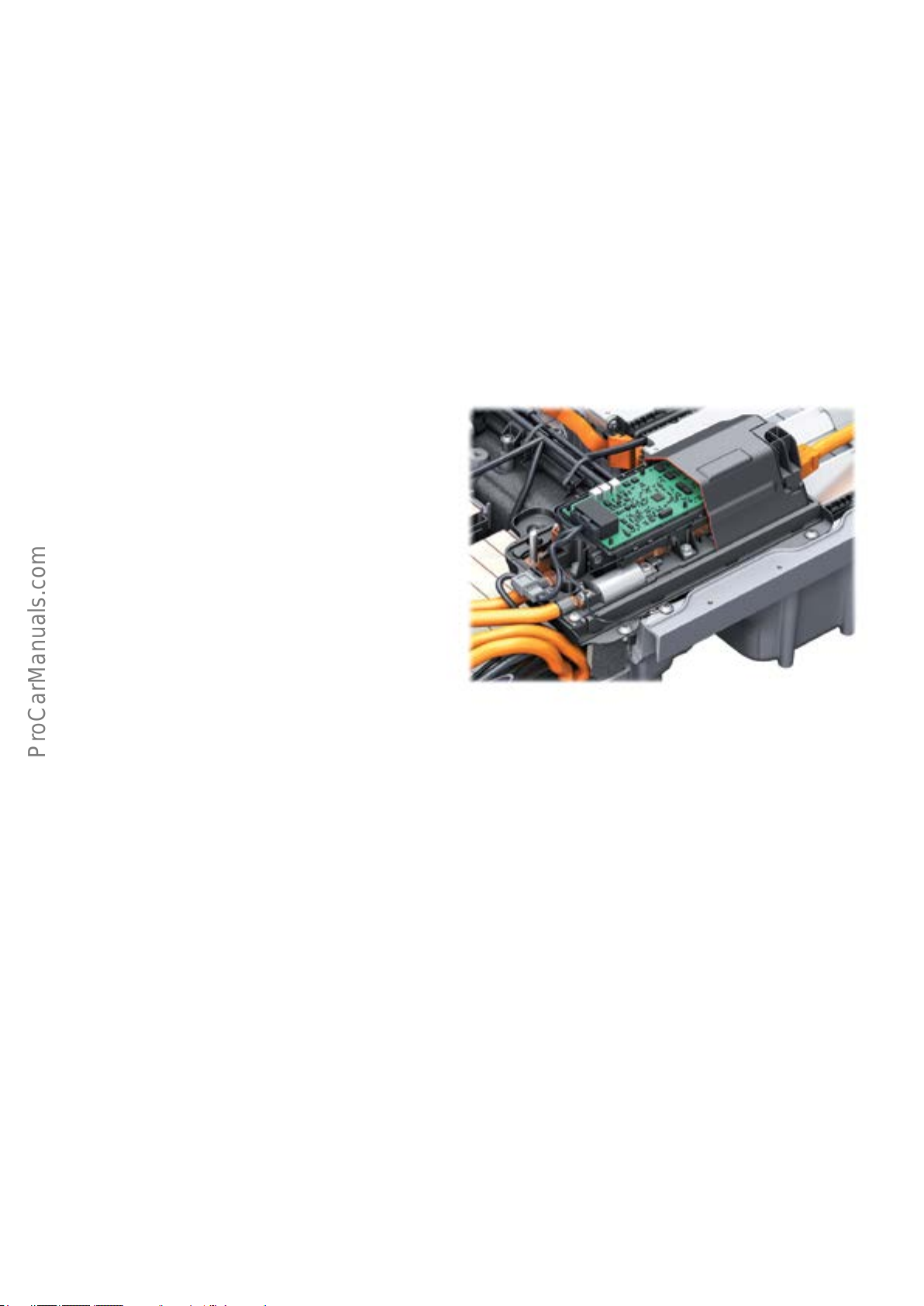
Battery Regulation Control Module J840
Battery Regulation Control Module J840 is bolted to Hybrid
Battery Unit AX1 from below.
It performs the following tasks:
• Measurement and evaluation of the battery voltage.
• Measurement and evaluation of the individual cell
voltages.
• Measurement of high voltage battery temperature.
• Regulation of high voltage battery temperature using
coolant circulation pump 2 and Solenoid Valve 1 N88 in
low-temperature circuit 2.
High voltage Battery Switch Box SX6
The following components are installed in SX6:
• Controller.
• High voltage System Fuse 2 S352.
• High voltage Battery Voltage Sensor G848.
• High voltage Battery Protection Resistor N662.
• Power contactor 1 of High voltage Battery Power Output
Protection 1 J1057 (HV pos.).
• Power contactor 2 of High voltage Battery Power Output
Protection 2 J1058 (HV neg.).
• Precharging contactor of High voltage Battery Pre-load
Protection J1044 (20Ω).
J840 communicates with other modules via the interfaces
to the Powertrain CAN and Hybrid CAN.
A crash signal is transmitted from Airbag Control Module J234
to J840 over the Powertrain CAN and a discrete wire. If a crash
signal is generated, the high voltage contacts are opened and
the high voltage system is deactivated. The control module
communicates with High voltage Battery Switch Box SX6 and
the eight cell controllers over a private CAN.
When terminal 15 is switched on, the power contactor 2 of
High voltage Battery Power Output Protection 2 J1058
(HV negative) and the precharging contactor of High
voltage Battery Pre-load Protection J1044 (20Ω) are at
rst closed. A small amount of current ows through the
resistor until the intermediate circuit capacitor 1 C25 in
Electric Drive Power and Control Electronics Module JX1 is
charged up. When the intermediate circuit capacitor is
charged up, the power contactor 1 of High voltage Battery
Power Output Protection 1 J1057 (HV positive) is closed
and then the precharging contactor of J1044 (20Ω) is
opened.
Cell controller
The cell controllers are a component part of the cell
module. The cell controllers measure the voltage of each
individual cell and, using an NTC resistor, the temperature
of the cell module and send this data to Battery Regulation
Control Module J840.
627_037
The power contactors are opened if at least one of the
following conditions is met:
• Terminal 15 switched o.
• A crash signal from Airbag Control Module J234 is
detected.
• Maintenance connector TW is opened.
• Fuse for power supply to power contactors terminal 30c
is disconnected.
• 12 volt power supply for Hybrid Battery Unit AX1 is
interrupted.
• Safety line open.
J840 evaluates the cell voltages and instructs the cell
controllers to discharge cells with high cell voltage through
a resistor. As a result, all cells achieve the same cell voltage
and Electric Drive Power and Control Electronics JX1 has
maximum capacity.
30
Page 35
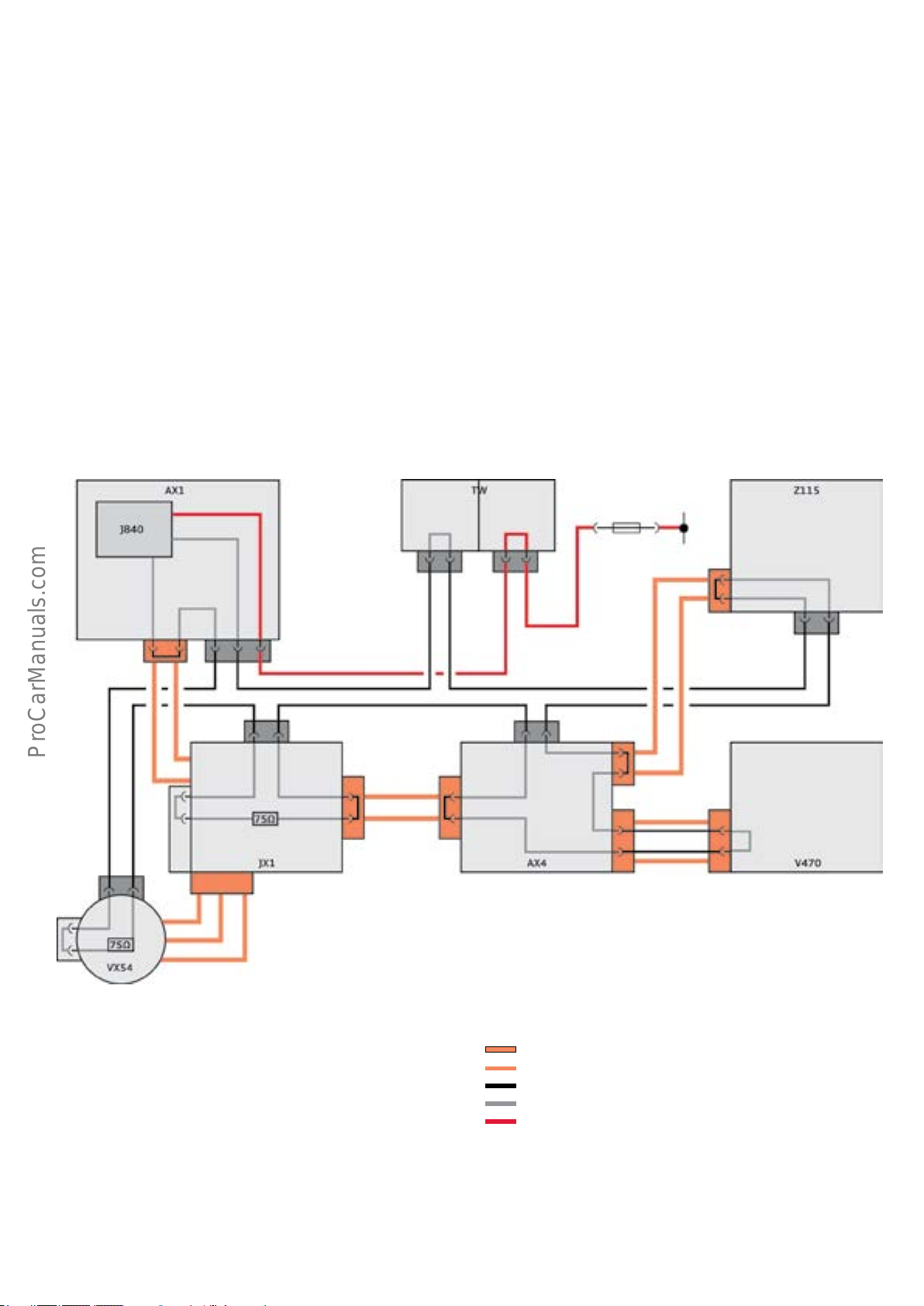
Insulation monitoring
When the high voltage system is active, High voltage
Battery Switch Box SX6 performs an insulation test every
60 seconds.
The resistance between the high voltage conductors and
the housing of the Hybrid Battery Unit AX1 is measured at
the rated voltage of 352 V.
Insulation faults in the high voltage components and high
voltage lines are detected.
Safety line
The safety line is a 12 volt ring wire which interconnects all
high voltage components in series. Battery Regulation
Control Module J840 inputs an electrical current of approxi-
mately 10 mA into the safety line and evaluates the current
ow. In addition, Electrical Drive Control Module J841
monitors the safety line.
The charging socket and the AC/DC inverter in the high
voltage charger are not tested due to the galvanic isolation
between 230V AC and 352V DC.
If an insulation fault is detected, a message is displayed in
the DIS. The customer is prompted to bring the vehicle in
for repair.
If the safety line is broken, the high voltage system is
immediately deactivated by J840. The high voltage contacts
are opened. The driver is notied via the display in the
instrument cluster.
S
Terminal
30c
Key:
AX1 Hybrid Battery Unit
AX4 High voltage battery charger 1
J840 Battery Regulation Control Module
JX1 Electric Drive Power and Control Electronics Module
S Fuse
TW High voltage System Maintenance Connector
V470 Electrical AC compressor
VX54 Three-phase Current Drive
Z115 High voltage Heater (PTC)
627_038
High voltage connector
High voltage line
Safety line outside of component
Safety line inside of component
Line to protect the power supply to the line contactors
31
Page 36
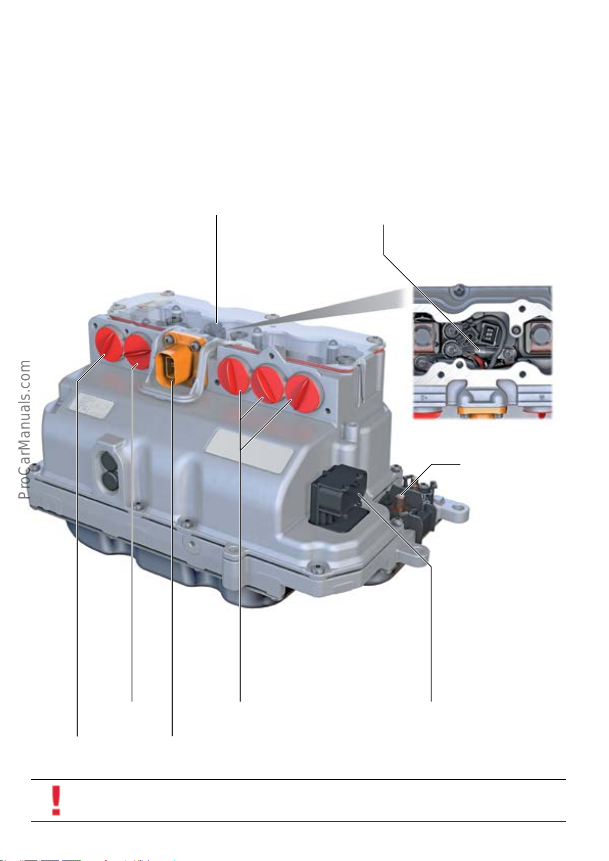
Electric Drive Power and Control Electronics Module JX1
JX1 is installed on the driver’s side of the engine compartment and has the following components:
• Electric Drive Control Module J841.
• Drive Motor Inverter A37.
• Voltage Converter A19.
• Intermediate Circuit Capacitor 1 C25.
• AC Compressor Fuse S355.
• Connections for high voltage lines.
• Connections for 12 volt electrical system.
• Coolant connections.
Safety line connector
The high voltage line from the high voltage charger is connected externally. All other high voltage lines are bolted
inside JX1. JX1 is connected to the vehicle chassis via an
equipotential bonding. JX1 is cooled by low-temperature
circuit 2.
A/C Compressor Fuse S355 is integrated in JX1 and is con-
nected between HV positive and HV positive of High Voltage
Battery Charger 1 AX4. AX4 is cooled in the low tempera-
ture cooling circuit.
A/C Compressor Fuse
S355
High voltage battery
HV positive
High voltage battery
HV negative
Electro-drive Drive Motor V141
Connections U, V, W
Connection for High voltage Battery Charger 1
AX4
12-volt positive charging line
627_039
12 volt on-board power plug
32
Information
To replace fuse S355, you must open Electric Drive Power and Electronic Control Module JX1. Always follow the instructions
given in the electronic service information and ODIS Service when doing this procedure.
Page 37
Electric Drive Control Module J841
Electric Drive Control Module J841 monitors the rotor
speed of Electro-drive Drive Motor V141 with Drive Motor
Rotor Position Sensor 1 G317.
The temperature of V141 is monitored by Drive Motor
Temperature Sensor G712 and relayed to the ECM.
Voltage Converter A19
A19 is a DC/DC converter that converts the 352 DC voltage
to the 12 DC voltage of the vehicle’s electrical system.
Intermediate Circuit Capacitor 1 C25
Another component of Electric Drive Power and Electronics
Control Module JX1 is Intermediate Circuit Capacitor 1 C25.
Its job is to stabilize voltage. Voltage uctuations can occur
during start-up or at transmission kick-down.
Electric Drive Control Module J841 monitors component
temperatures with sensors in Electric Drive and Control
Electronics Module JX1. This information is used by the ECM
to activate the coolant circulation pump upstream of
Coolant Pump in Front of Electric Drive Power and Control
Electronics V508 on demand. J841 is networked via the
Powertrain and Hybrid CAN systems.
A pulse inverter converts the voltage of the high voltage
battery of 12 volts. The voltage is transmitted to the
12-volt electrical system by coil induction (galvanic isola-
tion). As a result, there is no conductive connection
between the high voltage system and the 12-volt electrical
system.
C25 is discharged actively and passively at Terminal 15 o
or if the high voltage system is disabled due to a crash.
Passive discharge means that C25 is discharged through a
22K ohm resistor between HV positive and HV negative. In
the case of active discharge, a 1K ohm resistor is connected. This ensures that C25 is discharged in the least
possible time.
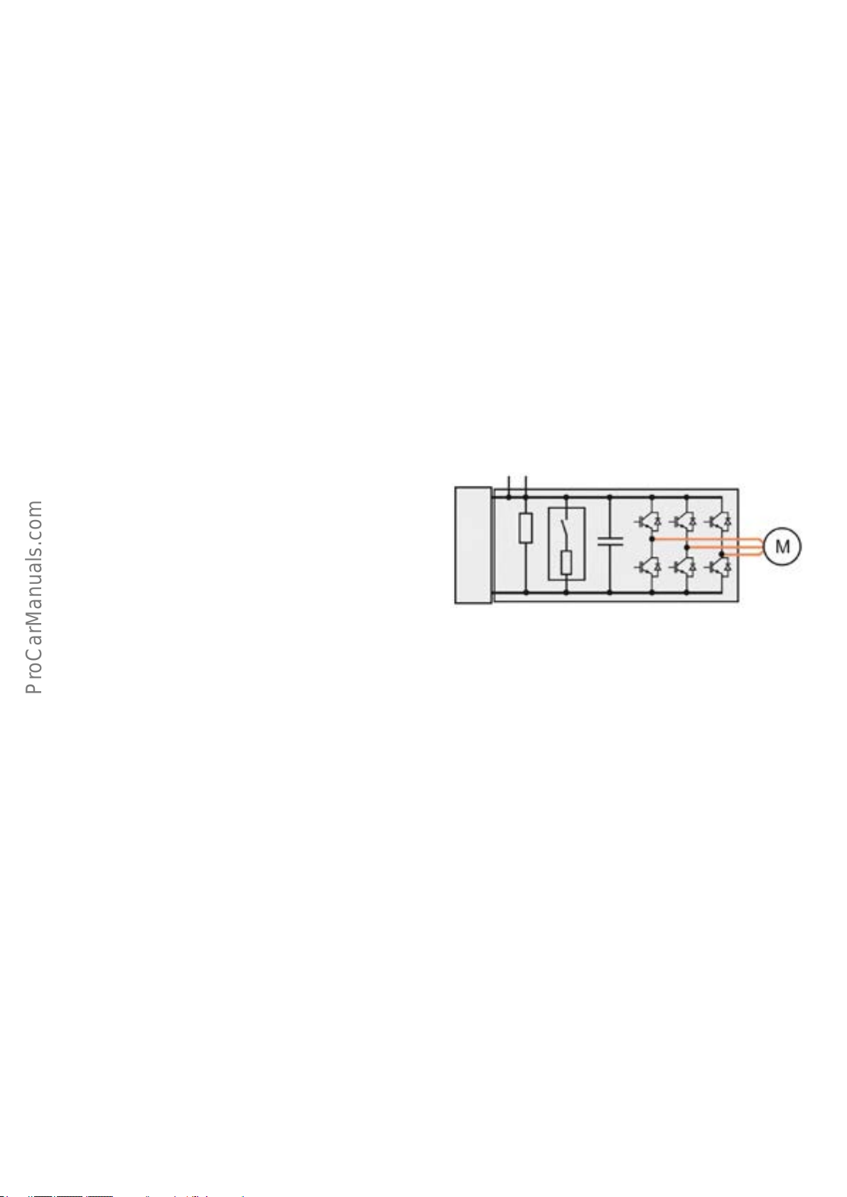
Drive Motor Inverter A37
The drive motor inverter A37 is both a DC/AC
converter and an AC/DC converter.
Electro-drive Drive Motor V141 (e-machine) as motor
In electric driving mode A37 converts the AC voltage of the
Hybrid Battery Unit AX1 to a 3-phase AC voltage. The
voltage is converted by pulse width modulation. There are
six transistors in A37. Two for each of the three phases, U,
V, and W. Each phase has a separate transistor for positive
and negative.
615_024a
Electro-drive Drive Motor V141 in generator mode
If V141 is running in generator mode A37 converts the
generated 3-phase AC voltage to a 352 V DC voltage. The
high voltage system is supplied with the generated DC
voltage and the 12-volt electrical system is supplied
through Voltage Converter A19.
When activated, the corresponding potential is connected.
The transistors are activated by Electric Drive Control
Module J841 using pulse width modulated signals. RPM is
regulated by changing the frequency, and the torque of
V141 by changing the activation times of the individual
pulse widths.
33
Page 38
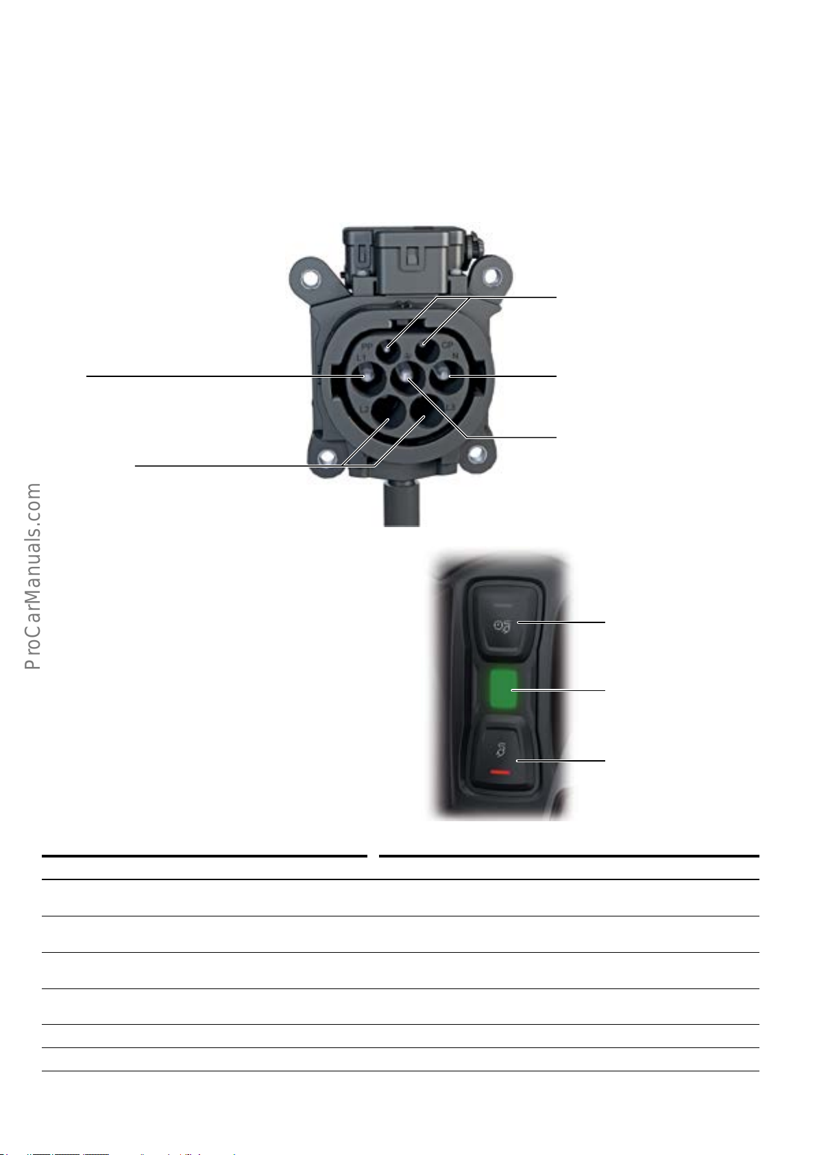
Charging
High Voltage Battery Charging Socket 1 UX4
High Voltage Battery Charging Socket 1 UX4 is located
behind a ap at the front of the radiator grille.
Both Charging Socket Temperature Sensor 1 G853 and High
voltage Charging Connector Lock 1 Adjuster F498 are
integrated with UX4.
L1
Phase1
Not assigned
It is connected to the vehicle chassis via equipotential
bonding.
Communication
Allows communication between vehicle
and charging station
N
Neutral conductor
PE
Protective earth (ground)
627_044
Charging button module with display
The charging button module has the following components:
• Intermediate Charging Button E766.
• Charging Prole Selection Button E808.
• Charging Socket LED Module 1.
L263 indicates the current status of the charging cycle
through various colors and by ashing or steady light. The
active charging option is indicated by the red LED in the
button.
Overview of status LED messages
Display Denition
LED is red Plug has been detected, but is not locked;
charging is not possible
LED is yellow Plug has been detected and is not locked, but no charging voltage is
available; charging is not possible
LED is ashing yelow Plug has been detected and is locked,
selector lever not in position P; charging is not possible
LED ashes green every 4s for 60s, then the
LED goes out
LED is ashing green Charging cycle is active
Timer for charging cycle is active, charging cycle starts depending on
the programmed departure time
Charging Prole Selection Button
E808
Charging Socket LED Module 1
L263
Intermediate Charging Button
E766
627_045
LED lights up green and then the LED goes out Charging cycle completed
34
Page 39
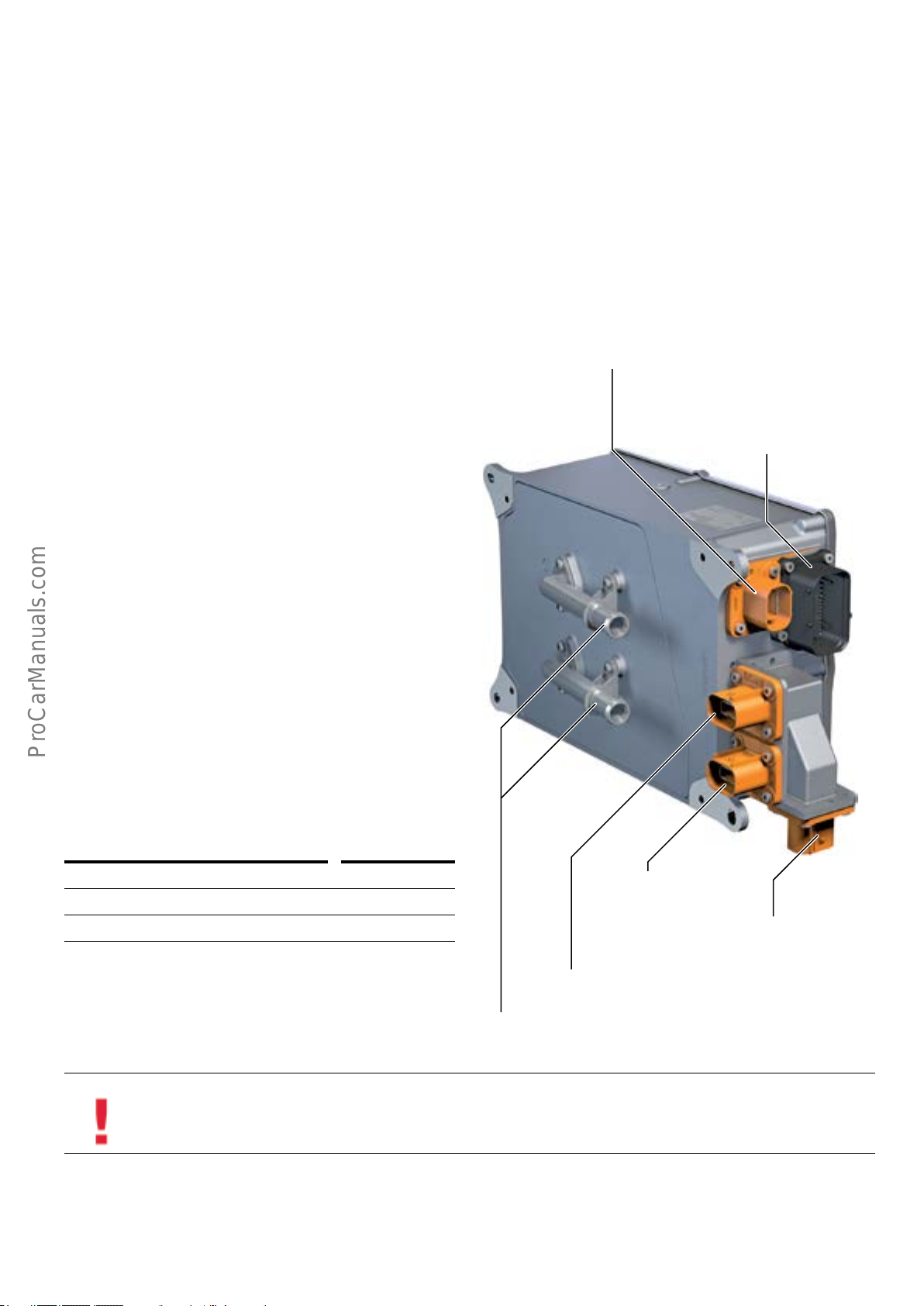
High Voltage Battery Charger 1 AX4
High Voltage Battery Charger 1 AX4 is connected to Electric
Drive Power and Control Electronics Module JX1 by a high
voltage line.
A pulse inverter which converts the AC voltage of the oper-
ating unit to a DC voltage for charging Hybrid Battery Unit
AX1 is integrated in AX4. The voltage is transmitted to the
high voltage onboard power supply by coil induction (gal-
vanic isolation). As a result, there is no conductive connection between the AC system and the high voltage system in
the vehicle. AX4 is connected to the vehicle chassis via an
equipotential bonding.
The following sensors are connected to High Voltage
Battery Charger Control Module J1050:
High Voltage Battery Charger Control Module J1050 is also
integrated with AX4. It is networked with other control
modules through the Powertrain CAN and Hybrid CAN.
J1050 has an internal coolant temperature sensor which
sends information to the ECM. The ECM can then activate
Coolant Pump in Front of Electric Drive Power and Control
Electronics V508 on demand.
Charging socket 1 for high voltage battery charging
UX4
12-volt connection for charging socket,
allows communication between vehicle and
charging station via UX4
• Charging Socket Temperature Sensor 1 G853 in High
Voltage Battery Charging Socket 1 UV4 in the High
Voltage Battery Charging Socket 1 UX4.
The following actuators are connected to High Voltage
Battery Charger Control Module 1 J1050:
• High Voltage Charge Flap Lock Adjuster F496.
• High Voltage Charging Connector Lock 1 Adjuster F498 in
High Voltage Battery Charging Socket 1.
Input voltage in V AC 100–240
Output voltage in V DC 220–450
Maximum current consumption 16 A
High Voltage Heater (PTC)
Z115
Electric Drive Power and Control Electronics Module
JX1
Coolant connections
627_043
Electrical A/C Compressor
V470
Information
Preset charging timers are stored in High Voltage Battery Charger 1 AX4.
35
Page 40
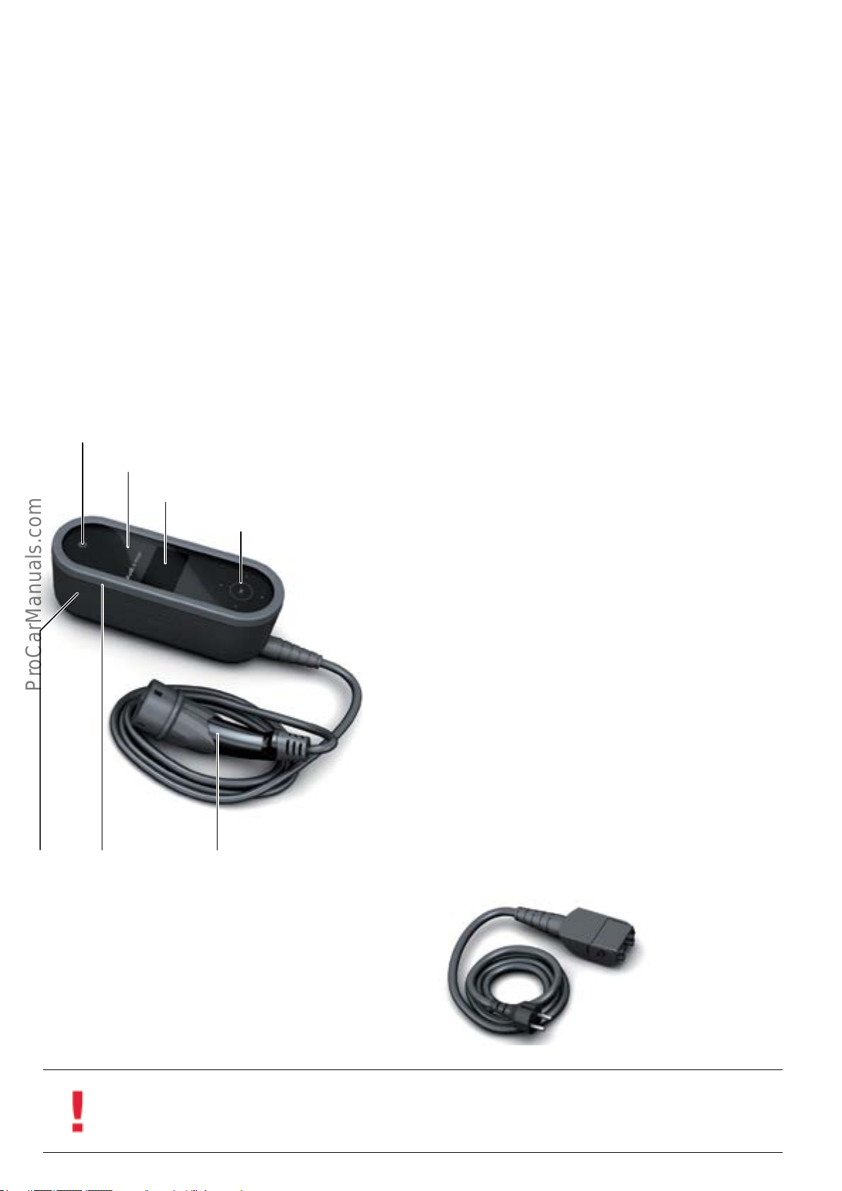
Charging the high voltage battery
Charging with alternating current
When the vehicle is using the internal combustion engine
to provide drive, the high voltage battery is charged via the
e-machine, which acts as a generator.
Audi e-tron charging system
The AudiA3Sportbacke-tron comes with the Audie-tron
charging system. For mobile use, the Audi e-tron charging
system can be carried in a transport case.
Two replaceable AC cables are supplied for connecting to a
three-phase AC supply. One cable is suitable for household
(120V) use while the other cable is for attaching to a 240V
AC source.
Status LED
Safety glass
Monochrome display
Capacitive operating panel
The high voltage battery can be charged with alternating
current from both a 240V AC or 120V AC voltage. Charging
the vehicle with AC voltage will allow for a greater range of
electric driving by charging the vehicle battery prior to
driving.
Operating unit
The cables are encoded in such a way that the operating
unit can detect whether a connection has been made with a
120V or 240V plug.
If the vehicle is connected with 240V AC source, the
maximum power consumption is 16 A, resulting in a
maximum charging output of 3.6 kW. If the vehicle is
connected to a 120V outlet, power consumption is limited
to 10 A.
The charging output can be set to 50% or 100% by the
user. If the vehicle is connected to 240V AC, a charging
output of 50% is set automatically. This setting is maintained until the charger unit is disconnected from the
vehicle or the wall socket.
To prevent unauthorized access, the operating unit can be
protected by entering a 4-digit PIN code. If a customer
were to forget their PIN number, it can be re-set by dealer-
ship personnel.
Vehicle cableHousing Protective frame
Before the charging cycle begins, the operating unit and
the high voltage charger unit in the vehicle communicate
with one another.
The operating unit has a self-diagnosis function and indi-
cates any faults detected via the display.
The operating unit has a temperature monitor. If the permissible temperature is exceeded, the charging cycle is
interrupted until the temperature returns to an acceptable
level.
627_024
Charging cable
A charging cable is connected from an AC power source to
the Audi e-tron charger unit.
627_025
36
Information
The charging cable must always be connected directly to a socket. Never use the charging cable together with an extension
cord, a cable drum, a multiple socket outlet or a timer. Failure to heed this warning can result in damage to the operating
unit or the home electrical system.
Page 41
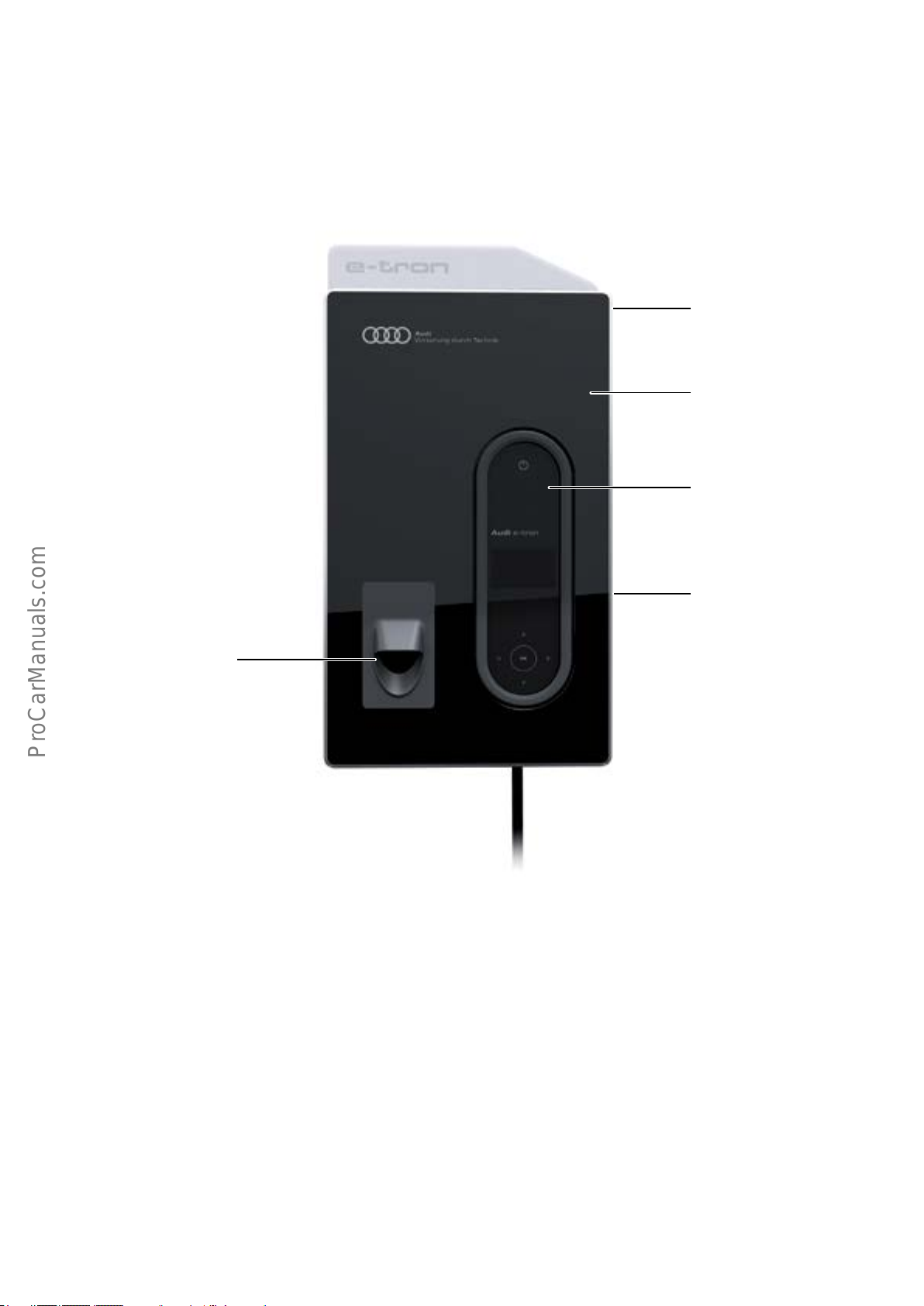
Charging at home
A charging dock for home installation is available. It can be
attached to a wall over a conventional household power
outlet.
The vehicle battery charger can be clipped into the charging
dock. Charging cables are available in various lengths for
connecting the vehicle to the charging dock.
Integrated mounting xture
available through Audi accessories
Fold-out front made from printed
safety glass
Front recess with mount for the
operating unit of Audi e-tron
charging system
Receptacle for the vehicle cable
with plug
Mechanical lock for securing the
supplied Audi e-tron charging
system
627_026a
37
Page 42
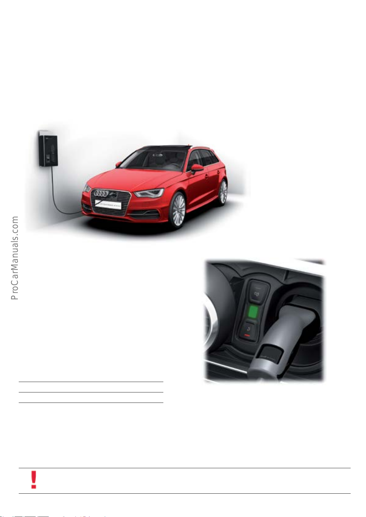
Charging cycle
To charge the high voltage battery, the charging cable must
be plugged into the charging dock.
When the charging cable is plugged into the vehicle, the
charging plug is locked and cannot be removed. This is
indicated by the yellow status LED.
The charging cycle starts when the selector lever is in
position P and the operating unit is connected to the AC
voltage source.
If no timer is programmed, the charging cycle starts immediately.
If a charging timer is programmed, but the state of charge
of the high voltage battery is less than 60%, the charging
cycle starts immediately until the state of charge reaches
approximately 60%. If the instant charge button is
pressed, the charging cycle stops and timer programming
is activated.
The active charging cycle is indicated by the ashing LED on
the relevant button (see page 34).
Displays of the status LED
The status LED ashes green during the charging cycle.
The charging cycle will stop if the vehicle is unlocked while
charging is in progress.
If the charging plug is not removed within 30 seconds of
unlocking the vehicle, the charging cycle will restart.
Charging times
The charging times are dependent on the AC voltage
source:
Household 120V 8 h
Commercial 240V 2h 15 min
627_028
627_029
38
Information
The vehicle cannot be started if the charging cable is plugged in. During the charging period, the 12 volt battery is also charged.
Page 43
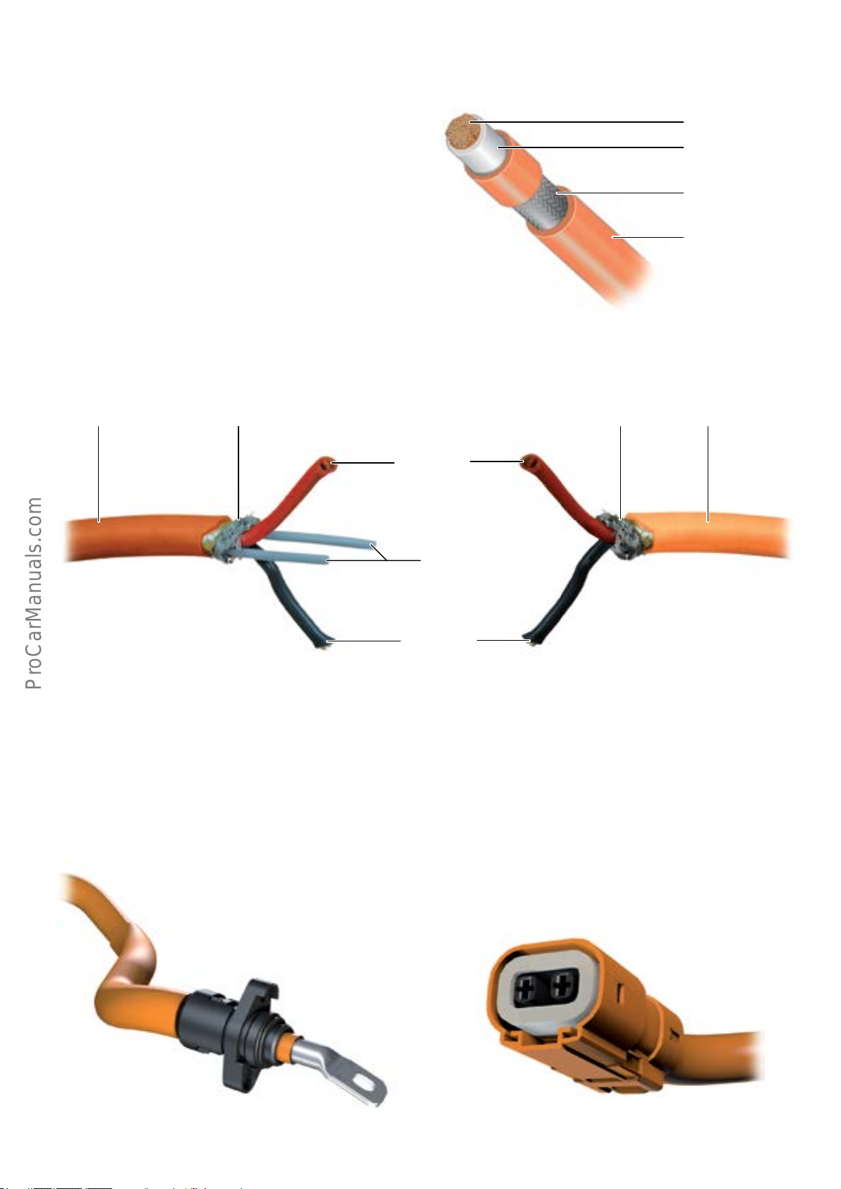
High voltage lines
All high voltage lines in the high voltage system are are
color-coded orange for identication. Due to the high
voltages and currents involved, the electrical lines have a
signicantly larger cross-section and are connected by
special plug-in contacts. The electrical lines of the high
voltage system dier from the other lines in the 12-volt
electrical system in terms of their core design.
The high voltage lines may also have a corrugated plastic
tube to provide protection against chang. Three dierent
types of high voltage line are used in the high voltage
system: single-pole and 2-pole lines with and without a
safety line.
2-pole high voltage line
Insulation Shielding
Single-pole high voltage line
Conductor
Insulation
Shielding
Insulation
627_052
Without safety lineWith safety line
InsulationShielding
HV positive
High voltage connections
The high voltage lines on the Audi A3 Sportback e-tron are
bolted onto or plugged into the high voltage components.
Bolted connection
• Electric Drive Power and Control Electronics Module JX1.
• Three-phase Current Drive VX54.
Safety line
HV negative
To avoid incorrect assembly, all connections are mechanically encoded.
2-pole plug connection
• Electric Drive Power and Control Electronics Module JX1
• High Voltage Battery Charger 1
• High Voltage Heater (PTC) Z115
1)
.
1)
.
• Electrical A/C Compressor V470.
627_053627_054
1)
.
627_055
1)
For these connections, a jumper for the safety line contacts is integrated into the plug.
627_056
39
Page 44
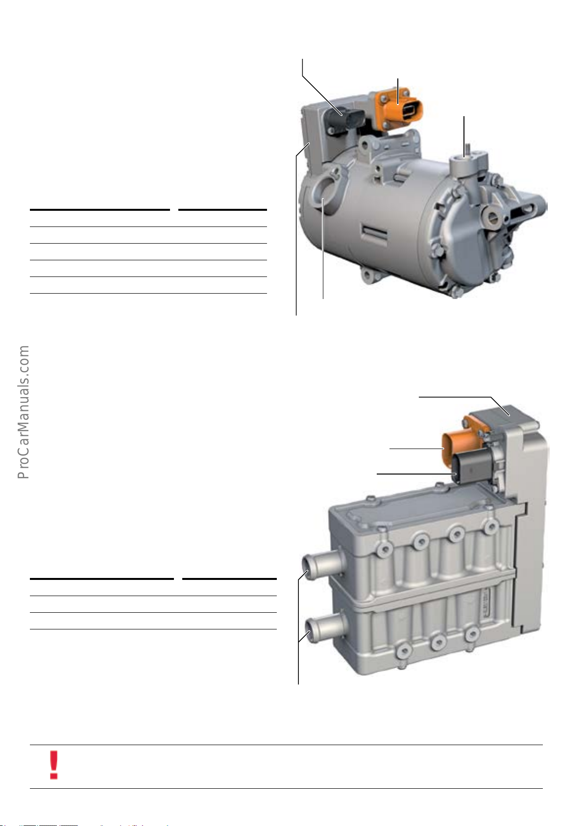
Electrical A/C compressor V470
Electrical A/C Compressor V470 is bolted to the front of the
internal combustion engine. There is no belt drive. It is
integrated with the high voltage electrical system via High
Voltage Battery Charger 1 AX4 and operates at 352 volts.
A/C Compressor Control Module J842 is integrated with the
compressor. J842 is controlled by Climatronic Control
Module J255 via a LIN bus. The A/C compressor is attached
by an equipotential bonding.
Type Scroll compressor
Rated voltage in V 352
Speed in RPM 800–8600
Power consumption in kW 3.6
Weight in kg 13.2 lb (6 kg)
12 volt electrical system
Electric Drive Power and Control Electronics
Module JX1
Condenser connection
627_040
Refrigerant circuit connection
High Voltage Heater (PTC) Z115
When the vehicle is driven in electric-only mode, Z115
heats the engine coolant for the passenger compartment
heat exchanger. It is bolted to the vehicle underbody and
connected to High Voltage Battery Charger 1 AX4 by a high
voltage line. The integrated High Voltage Heater (PTC)
Control Module J848 is controlled by Climatronic Control
Module J255 by a LIN bus connection.
J848 monitors the inlet and outlet temperatures of the
engine coolant via temperature sensors and send the information to J255. J255 determines the required heating
output and sends this information to J848 as a value
between 0 and 100%.
Rated voltage 352
Heating levels 3
A/C Compressor Control Module
J842
High Voltage Heater (PTC) Control Module
J848
High voltage line connection
12-volt electrical system
Activation mechanism PWM signal 0–100%
Information
All A/C timer information is stored in Climatronic Control Module J255.
40
627_041
Coolant connections
Page 45
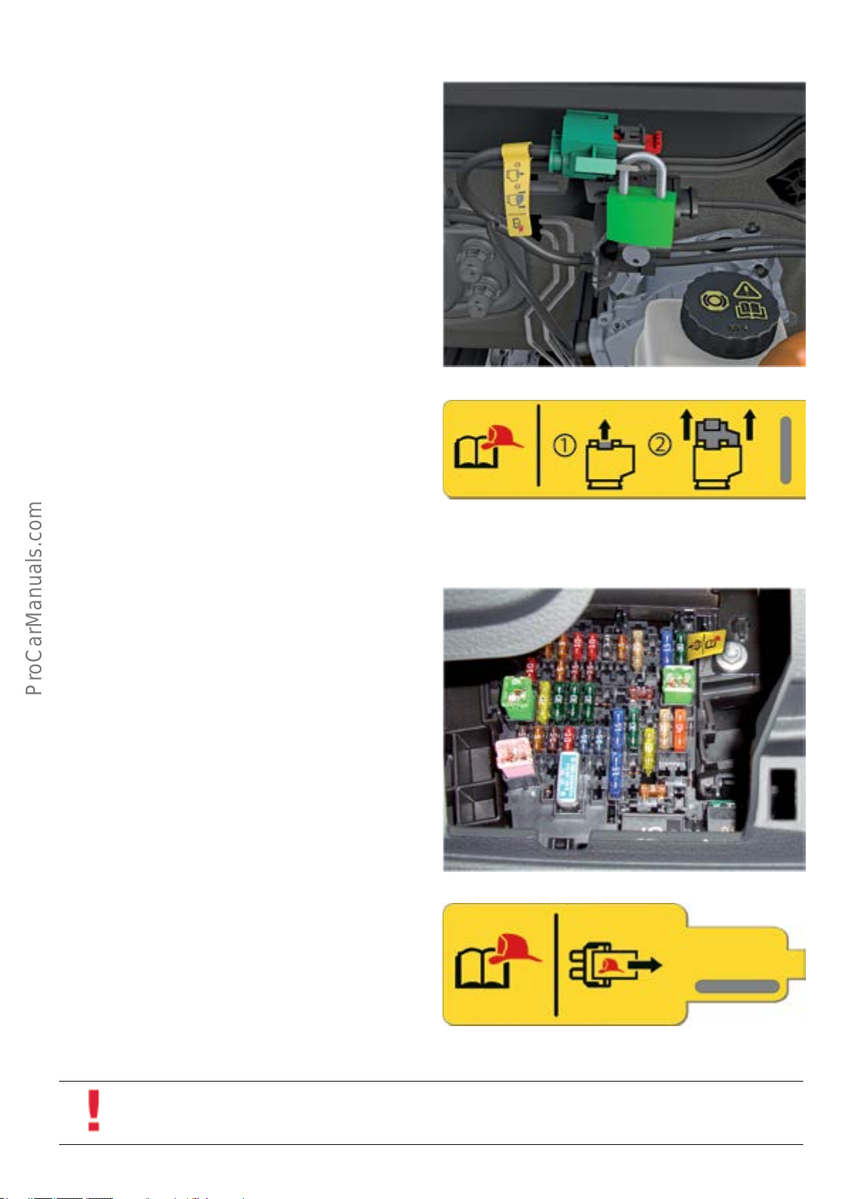
High Voltage System Maintenance Connector TW
High Voltage Electrical System Maintenance Connector TW
is located in the engine compartment. It serves as an
electrical connection in the 12 volt control circuit for the
high voltage battery contacts and as a component part of
the safety line.
Opening TW opens the safety line and breaks the 12 volt
control circuit of the high voltage power contacts. TW
serves to de-energize the high voltage system.
The VAS Scan Tool must be used to properly de-energize the
high voltage system. After TW is opened, it must be
secured with padlock T40262/1 to prevent it from being
accidentally reconnected.
In the engine compartment
The maintenance connector TW is labelled.
Fuse panel in passenger compartment
The power supply fuse for the control circuit of the power
contacts is labelled. This fuse is to be utilized by rst
responders in an emergency situation.
627_057
627_058
627_059
627_060
Information
After de-energizing the system, a check must be made to ensure that no voltage is present by running the relevant Test Plan
in ODIS Service.
41
Page 46

Hybrid manager
The software of Engine Control Module J623 has been
extended to include the hybrid manager function.
• Operating strategy.
• Torque distribution to Electro-drive Drive Motor V141
and the internal combustion engine.
• High voltage coordinator.
• Recuperation under braking and acceleration.
• Control of the coolant circuits.
Operating strategy
The operating strategy is congured to operate the vehicle
eciently using both drive systems. Taking the ambient
conditions and information from other control modules as
well as the driving prole into account, the system decides
whether to use the internal combustion engine, the e-ma-
chine or both.
The following hybrid-specic functions of the vehicle are
controlled by the hybrid manager.
• Control of hybrid displays.
• Power meter.
• Display in dash panel insert.
• MMI energy ow diagrams.
• e-tron statistics.
Electric driving also requires enabling signals from other
control modules. A low state of charge in the high voltage
battery, a too-low ambient temperature, high torque
demand or high cabin heating demand may necessitate
starting the internal combustion engine.
Internal combustion engine is: Electro-drive Drive Motor V141
serves as:
Internal combustion engine start o Electric motor
Electric drive o Electric motor
Drive by internal combustion
engine
Hybrid drive on Electric motor
Boost on Electric motor
Recuperation with and without
electrical braking
1)
In this operating mode, the 12-volt electrical system is supplied by Hybrid Battery Unit AX1.
on Generator
on or o Generator
1)
1)
1)
1)
High voltage coordinator Recuperation under braking and
acceleration
In its capacity as a high voltage coordinator, the hybrid
manager monitors and coordinates all high voltage components. It enables activation of the high voltage system and
controls the displays for hybrid operation and display of
messages for the driver.
The hybrid manager controls over-run and braking recuper-
ation functions based on the position of the accelerator or
brake pedal, the state of charge of the high voltage battery,
the vehicle's speed and driving stability criteria.
42
Page 47
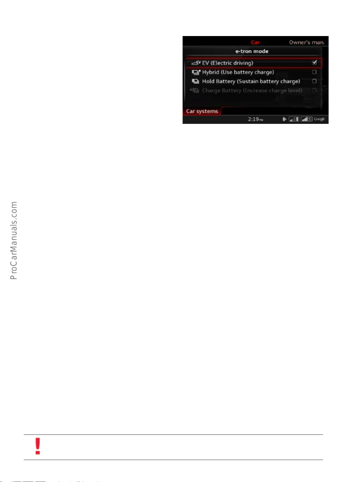
Plug-in hybrid modes
Electric driving (EV)
When the ignition is on, EV mode is active and the vehicle
preferentially runs on electric-only mode provided the
conditions for this are met.
EV mode is only active if the state of charge of the high
voltage battery is sucient and the following conditions
are met:
• The temperature of the 12-volt battery and of the high
voltage battery is not less than approximately
14 °F (-10 °C).
• The vehicle is not travelling faster than approximately.
80 mph (130 km/h).
• No kick-down is performed.
• The selector lever is not engaged in the S position.
If one or more of the above conditions is not met, EV mode
is deactivated.
Use battery charge (Hybrid Auto)
627_066a
A decision is made based on the driving prole whether to
start in Hybrid mode or to run on electric power.
When the route guidance function is active in the navigation system, the use of electrical power is optimized
through moderate recharging or startup of charging stations based on the predictive route data.
Hold battery charge (Hybrid Hold)
During vehicle operation, the state of charge of the high
voltage battery is held at a constant level. The vehicle runs
in Hybrid mode and uses only a small portion of the battery
charge.
Increase battery charge (Hybrid Charge)
During vehicle operation, the high voltage battery is
charged by the internal combustion engine more inten-
sively (this involves higher fuel consumption) in order to
achieve longer electrical range, for example, at the destination.
Sport mode
Moving the selector lever into tiptronic or S reveals the
sporty side of the AudiA3Sportbacke-tron. Full drive
power is now available to the driver at any time, and the
high voltage battery is continuously recharged. Increased
over-run torque boosts recuperation capacity and provides
a sporty driving feel.
Information
These settings can be made in the "Car" menu under "Systems" in the menu item "e-tron mode" or by pressing Electric Drive
Button E656 several times.
43
Page 48
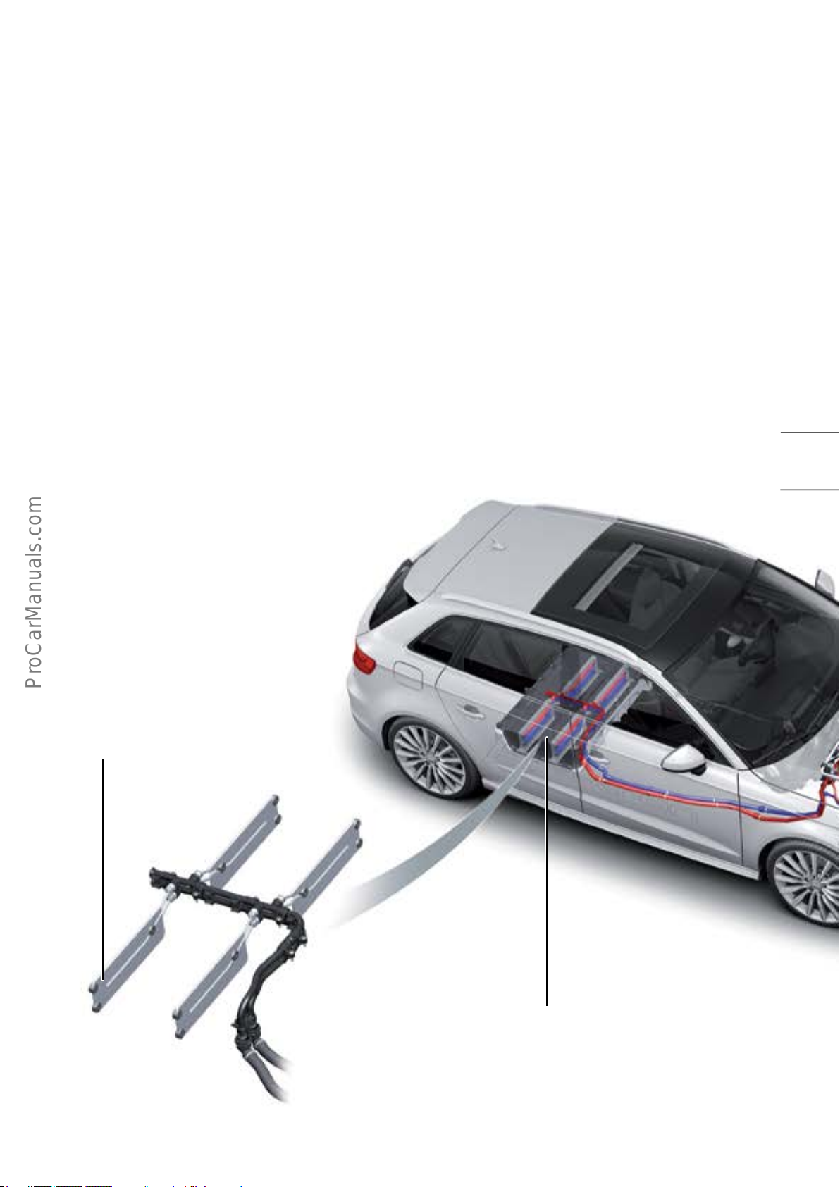
Climate control
Cooling systems, climate control and thermal management
The cooling and climate control systems of the A3 Sportback e-tron provide passenger comfort, cooling of the
internal combustion engine, transmission and high voltage
components. All components are integrated into the
various cooling circuits.
The thermal management system enables the components
to reach their operating temperatures quickly. Passenger
comfort has the highest priority.
Overview of cooling system
In the various operating states, for example in electric drive
mode or in Boost mode, the cooling circuits provide the
optimal coolant ow in order to ensure operational reliability,
a high level of passenger comfort and a high overall level of
eciency.
High Voltage Heater (PTC)
Z115
Coolant expansion tank 1
Heat sink of Hybrid Battery Unit
AX1
Hybrid Battery Unit
AX1
44
Page 49
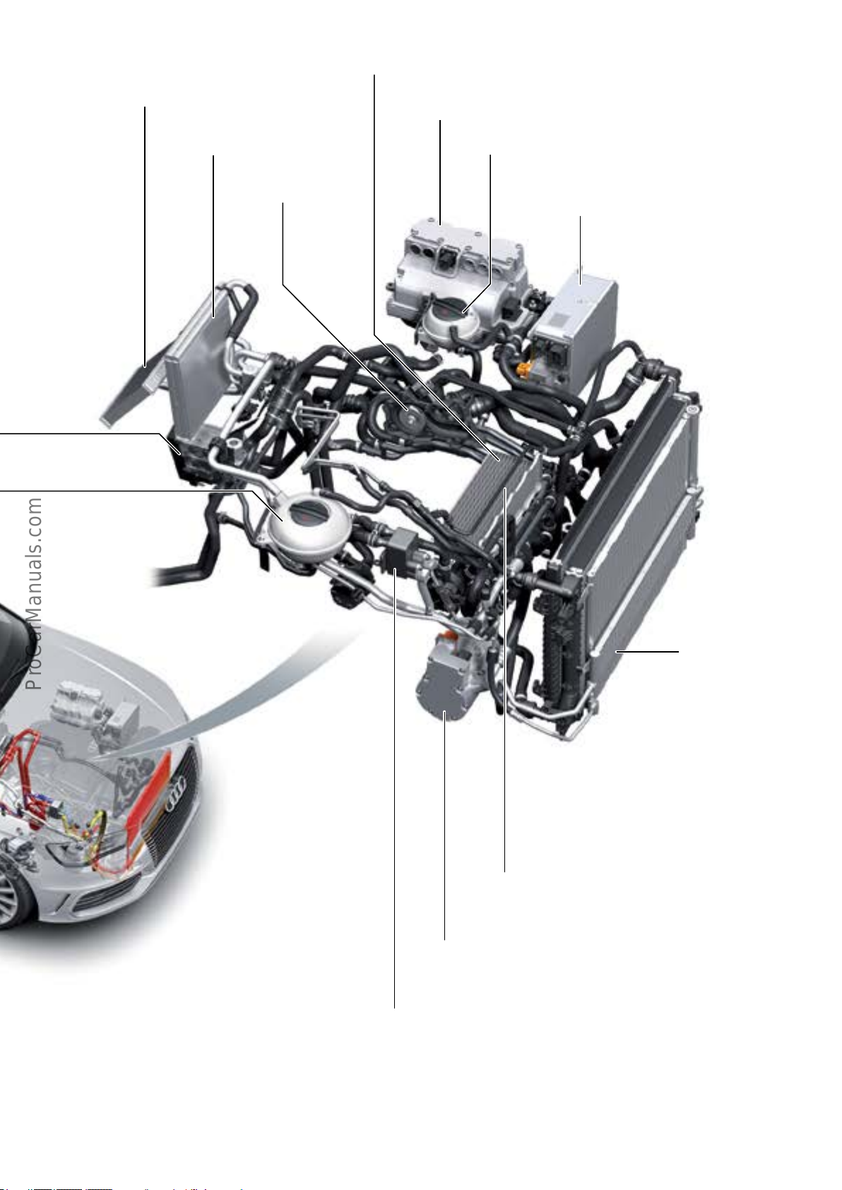
Thermostat 1
Heating heat exchanger
Coolant pump
Electric Drive Power and Control Electronics Module
JX1
Coolant expansion tank 2Evaporator
High Voltage Battery Charger Control Module
J1050
Charge air cooler
Electrical A/C Compressor
V470
High voltage battery heat exchanger
(cooler)
Radiator unit
627_009
45
Page 50
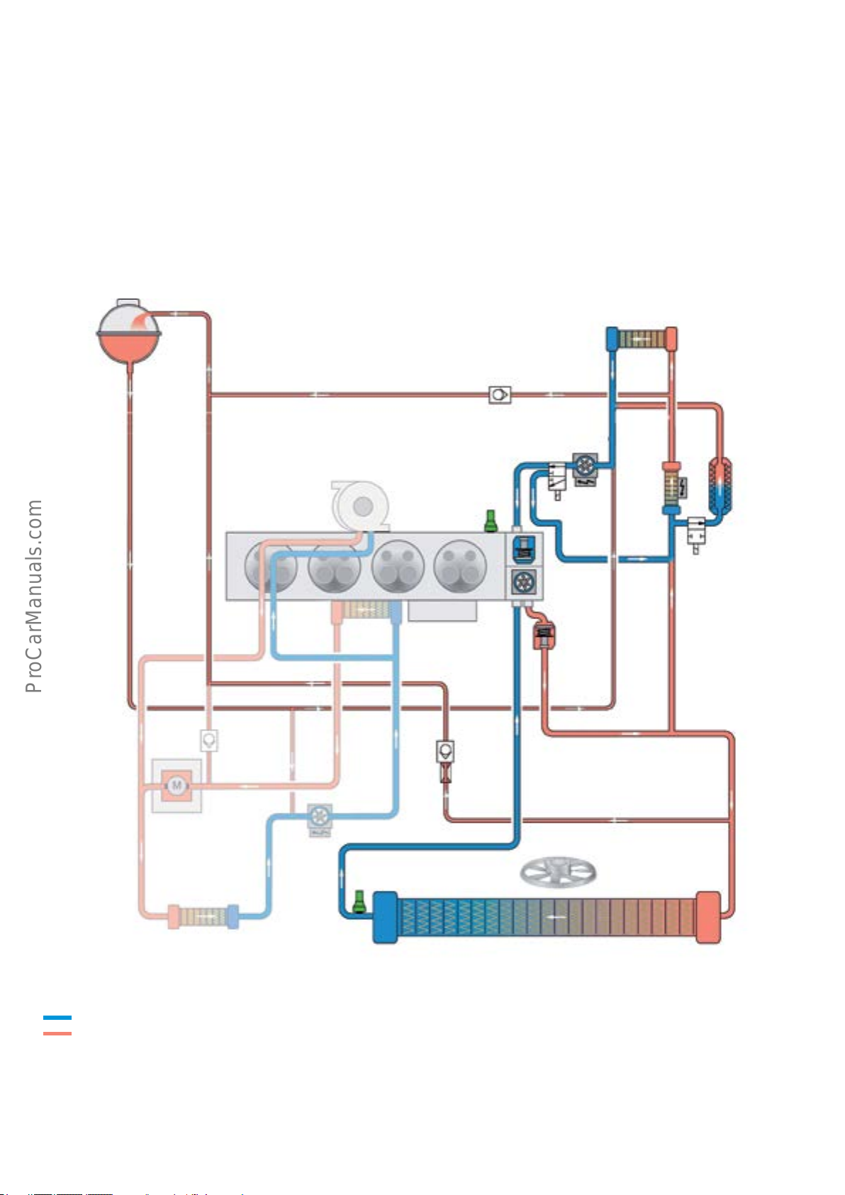
High-temperature coolant circuit
The high-temperature coolant circuit represents the actual
coolant circuit of the internal combustion engine. The
system is a twin-circuit cooling system which enables
dierent coolant temperatures to be achieved in the cylin-
der head and the engine block.
The temperature level in the high-temperature coolant
circuit is, on average, between 188 - 221 °F ( 87 - 105 °C).
1
4
Components of the high-temperature coolant circuit:
• Coolant expansion tank 1.
• Heating heat exchanger.
• Gear oil cooler.
• Coolant pump with thermostat.
• Engine oil cooler.
• High Voltage Heater (PTC) Z115.
• Radiator.
3
2
6
7
8
5
10
18
2
21
19
22
15
14
11
9
12
13
2
20
24
23
Key:
Cooled coolant
Heated coolant
1 Coolant expansion tank 1
2 One way check valve
3 Heater heat exchanger
4 Exhaust turbocharger
5 Engine Coolant Temperature Sensor G62
46
627_010b
6 Coolant Change-over Valve N633
7 High Temperature Circuit Coolant Pump V467
8 High Voltage Heater (PTC) Z115
9 Transmission Coolant Valve N488
10 Transmission oil cooler (ATF heat exchanger)
11 Thermostat1
12 Coolant pump
Page 51
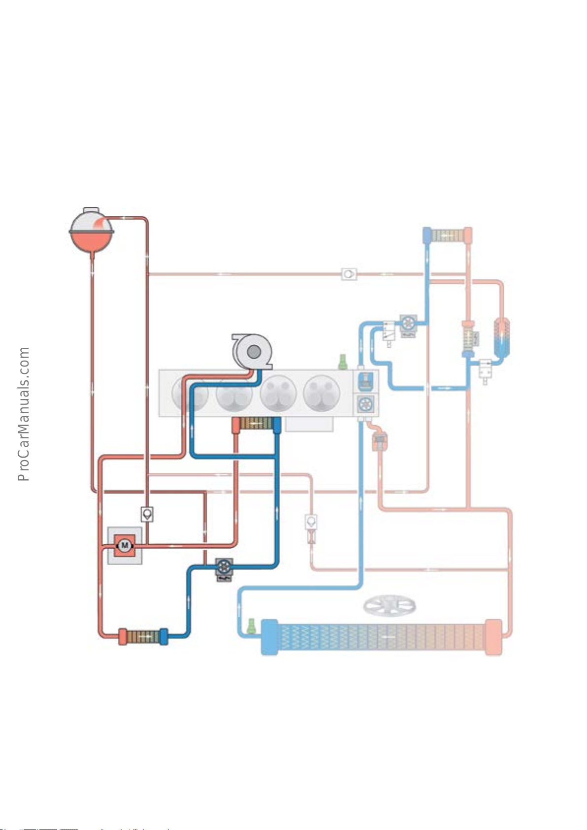
Low-temperature coolant circuit 1
Low-temperature coolant circuit 1 represents the coolant
circuit of the internal combustion engine's charge air
cooling system. This low-temperature coolant circuit is an
independent cooling circuit in the 1.4l TFSI engine. The
low-temperature coolant circuit uses the same coolant
expansion tank as the high-temperature coolant circuit.
During use of the 1.4l TFSI in the AudiA3Sportbacke-tron,
the e-machine is also integrated into low-temperature
coolant circuit 1.
1
4
The temperature level in low-temperature coolant circuit 1
is, on average, between 167 - 194 °F (75°C - 90°C).
Components of low-temperature coolant circuit 1:
• Exhaust turbocharger.
• Charge air cooler.
• Three-phase Current Drive VX54.
• Low Temperature Circuit Coolant Pump V468.
3
2
7
6
8
5
10
18
21
11
12
15
2
19
22
14
13
2
20
24
23
9
13 Thermostat2
14 Engine oil cooler
15 Charge air cooler integrated into intake manifold
18 Three-phase Current Drive VX54
19 After-run Coolant Pump V51
627_011b
20 Flow restrictor
21 Radiator for charge air cooling
22 Engine Coolant Temperature Sensor on Radiator Outlet G83
23 Radiator
24 Radiator Fan V7
47
Page 52
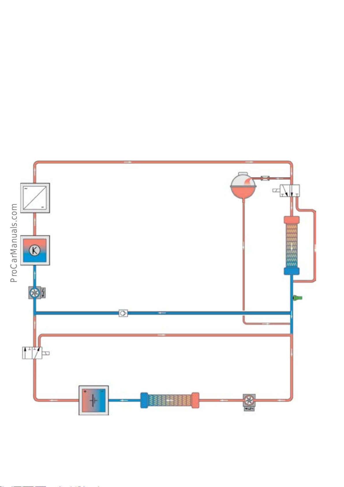
Low-temperature coolant circuit 2
The high voltage modules are grouped together in
low-temperature coolant circuit 2. The high voltage components are temperature-critical and require a constant
temperature below the average temperature in low-tem-
perature coolant circuit 1.
This low temperature is achieved by using a completely
separate, second coolant circuit. This circuit has its own
coolant equalization tank and is implemented by a coolant
recirculation pump upstream of Coolant Pump in front of
Electric Drive Power and Control Electronics Module V508
and the High Voltage Battery Coolant Pump V590.
The temperature level in low-temperature coolant circuit 2
is, on average, between 68 - 104 °F (20°C - 40°C).
13
Components of low-temperature coolant circuit 2
• Coolant expansion tank 2.
• Electric Drive Power and Control Electronics Module JX1.
• High voltage battery charger control module.
• High voltage battery heat exchanger.
• Hybrid Battery Unit AX1.
• Coolant Pump in front of Electric Drive Power and
Control Electronics Module V508.
• High Voltage Battery Coolant Pump V590.
1
2
3
12
11
10
4
5
6
9
78
48
627_012
Page 53
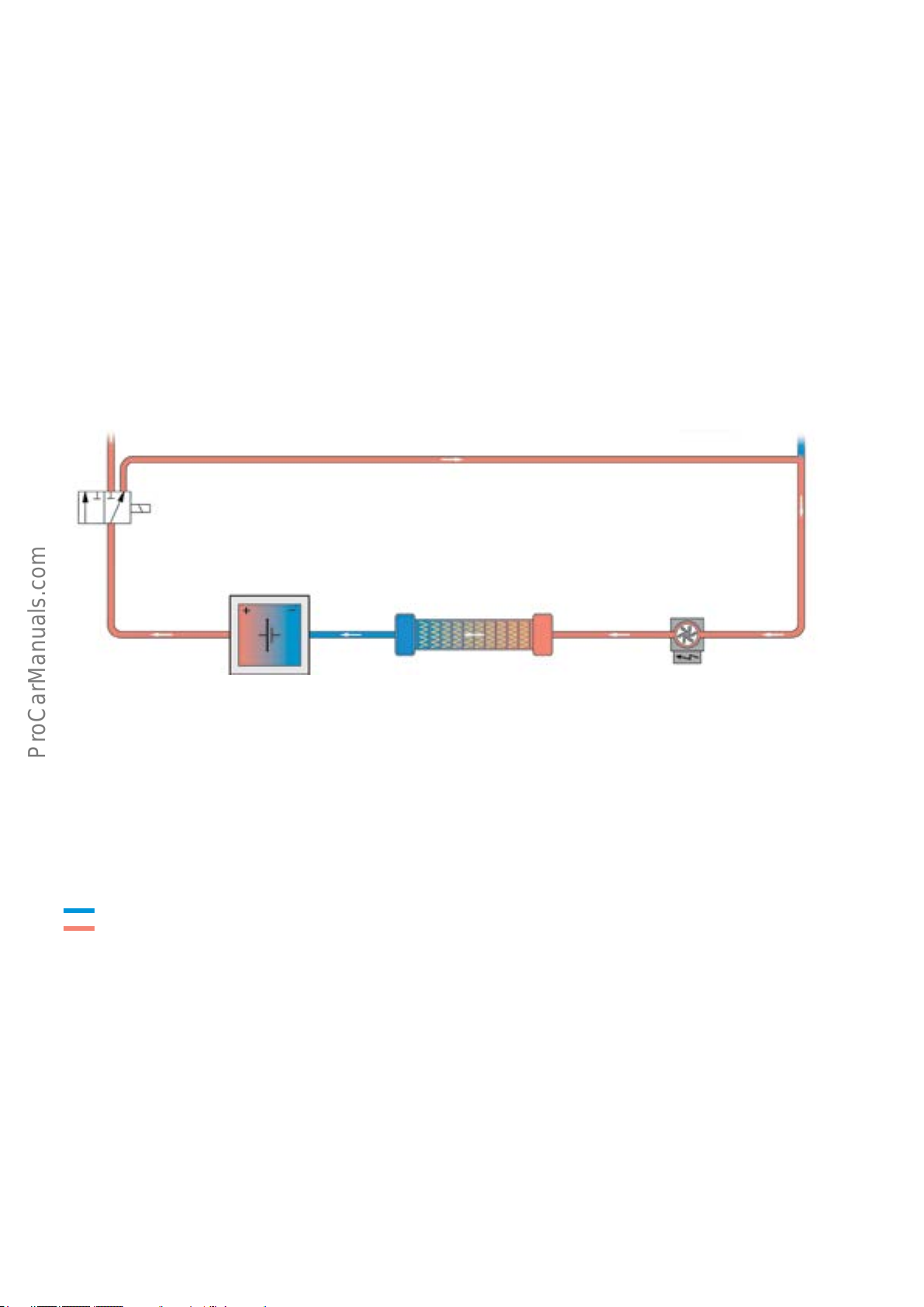
Coolant circuit of the high voltage battery heat exchanger
Low-temperature coolant circuit 2 can also be subdivided into
2sub-circuits, allowing dierent temperatures and, thus,
dierent component temperature requirements to be met.
A shortened circuit can be implemented by means of the
High Voltage Battery Coolant Valve N688 and High Voltage
Battery Coolant Pump V590. The sole task of this circuit is
to control the temperature of the Hybrid Battery Unit AX1
through the high voltage battery heat exchanger, which is
also an integral part of the coolant circuit.
10
The required temperature in low-temperature coolant
circuit 2 can be obtained by passive cooling (using lowtemperature radiator 2) or by active cooling (using the high
voltage battery heat exchanger).
Key:
Cooled coolant
Heated coolant
1 Coolant expansion tank 2
2 Flow restrictor
3 Coolant Change-over Valve 1 N632
4 Low-temperature radiator 2
5 Temperature sensor upstream of JX1
6 Non-return valve
9
78
627_013
7 High Voltage Battery Coolant Pump V590
8 High Voltage battery heat exchanger (cooler)
9 Hybrid Battery Unit AX1
10 High Voltage Battery Coolant Valve N688
11 Pump for coolant circulation upstream of V508
12 Electric Drive Power and Control Electronics Module JX1
13 High Voltage Battery Charger Control Module J1050
49
Page 54
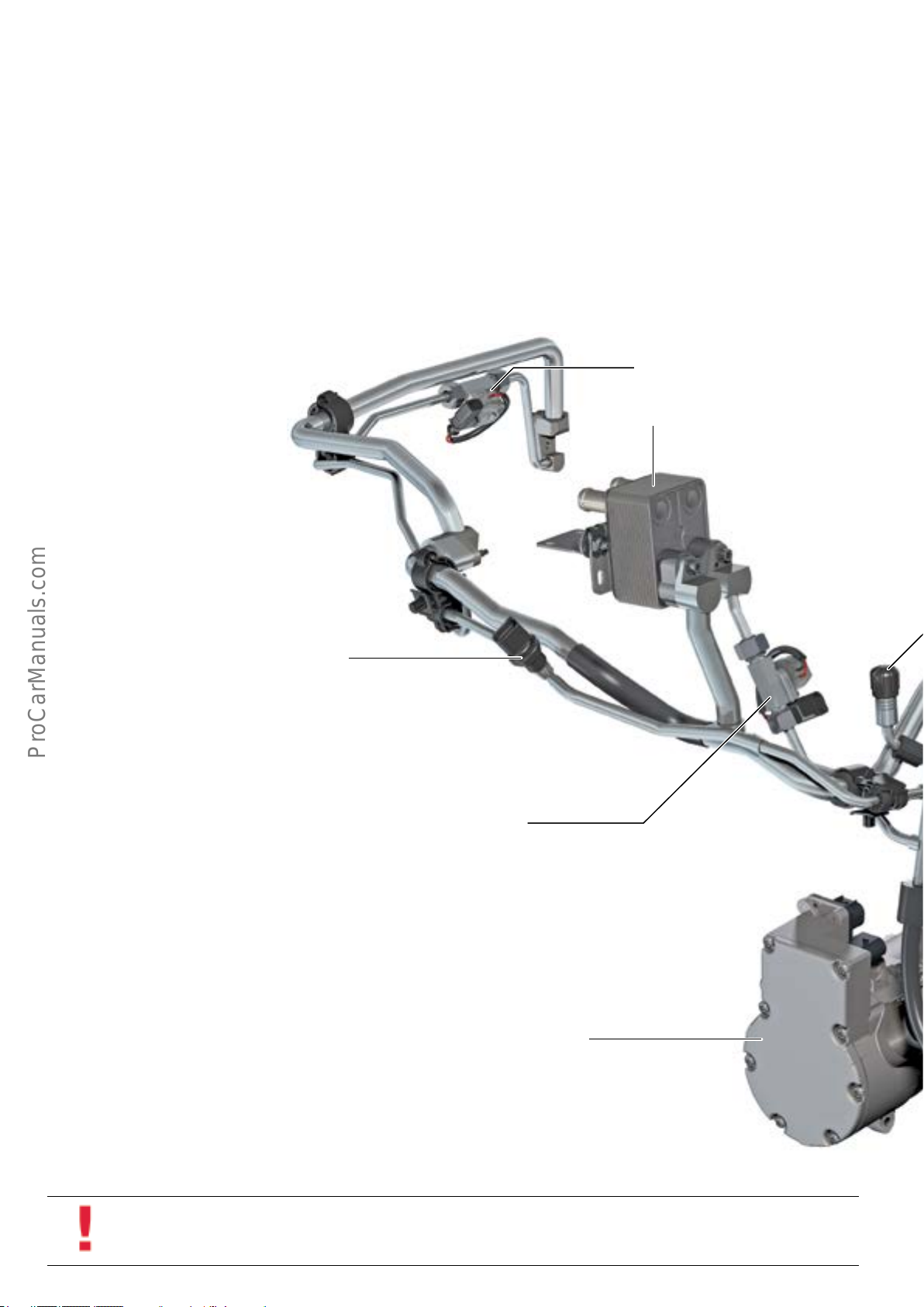
Refrigerant circuit
The A/C refrigerant circuit of the A3 Sportback e-tron
diers from other A3 models.
Electrical A/C Compressor V470 can, if required, be used for
cooling Hybrid Battery Unit AX1 as well and the passenger
compartment of the vehicle.
The refrigerant circuit from the A/C compressor to the
expansion valve has separate high low pressure lines (but
no internal heat exchanger is used).
A ow restrictor with a 0.7 mm diameter is integrated into
the high pressure refrigerant line to the high voltage
battery heat exchanger.
There are dierent high-pressure lines with built in or
inserted ow restrictors. Inserted ow restrictors can be
installed with a pre-screen.
R134a refrigerant is used. However, SPA2 PAG oil is used.
This dierent from the PAG oil used in mechanically driven
A/C compressors.
Expansion valve
High voltage battery heat exchanger
(cooler)
Refrigerant Circuit Pressure Sensor
G805
(ECE variant shown)
High Voltage Battery Heater Core Refrigerant Shut-o Valve
N542
Electrical A/C Compressor
V470
50
Information
The quantity of refrigerant and air conditioning refrigeration oil can deviate from the quantity of refrigerant and air conditioning refrigeration oil in other Audi A3 models and is specied in the current version of ElsaPro.
Page 55
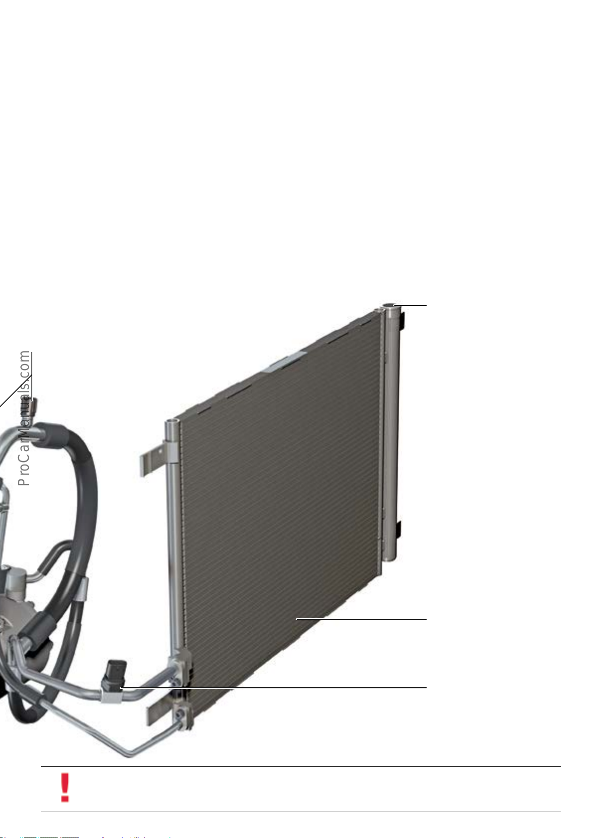
Flushing process notes
If repairs are required, it may be necessary to ush the
refrigerant circuit in the AudiA3Sportbacke-tron. The
following general conditions must be observed:
• It is not possible to drain the PAG oil from Electrical A/C
Compresor V470. There is no drain plug. It must be
ushed in order to determine the quantity of oil. The
compressor is always ushed in the direction of ow.
Service connections
The refrigerant circuit is ushed in two phases:
• In the rst ushing cycle, the circuit is ushed
together with the evaporator. A ushing adapter - VAS
6338/38 is installed in the refrigerant circuit in place
of the expansion valve.
• In the second ushing cycle, the circuit is ushed
together with the evaporator in the high voltage
battery heat exchanger.
To ensure a constant refrigerant ow during the ushing cycle, the inserted ow restrictor (0.7 mm diam-
eter) must be removed beforehand. In the case of a
built in ow restrictor, the orce must be drilled out to
a diameter of 5.0 mm. This refrigerant line must be
replaced after the ushing process is completed.
Receiver/Drier for refrigerant
circuit for refrigerant circuit
627_014
Condenser
A/C Pressure/Temperature Sensor
G395
(NAR variant)
Information
Always look for the latest repair procedures in ElsaPro regarding the refrigerant ushing process.
51
Page 56
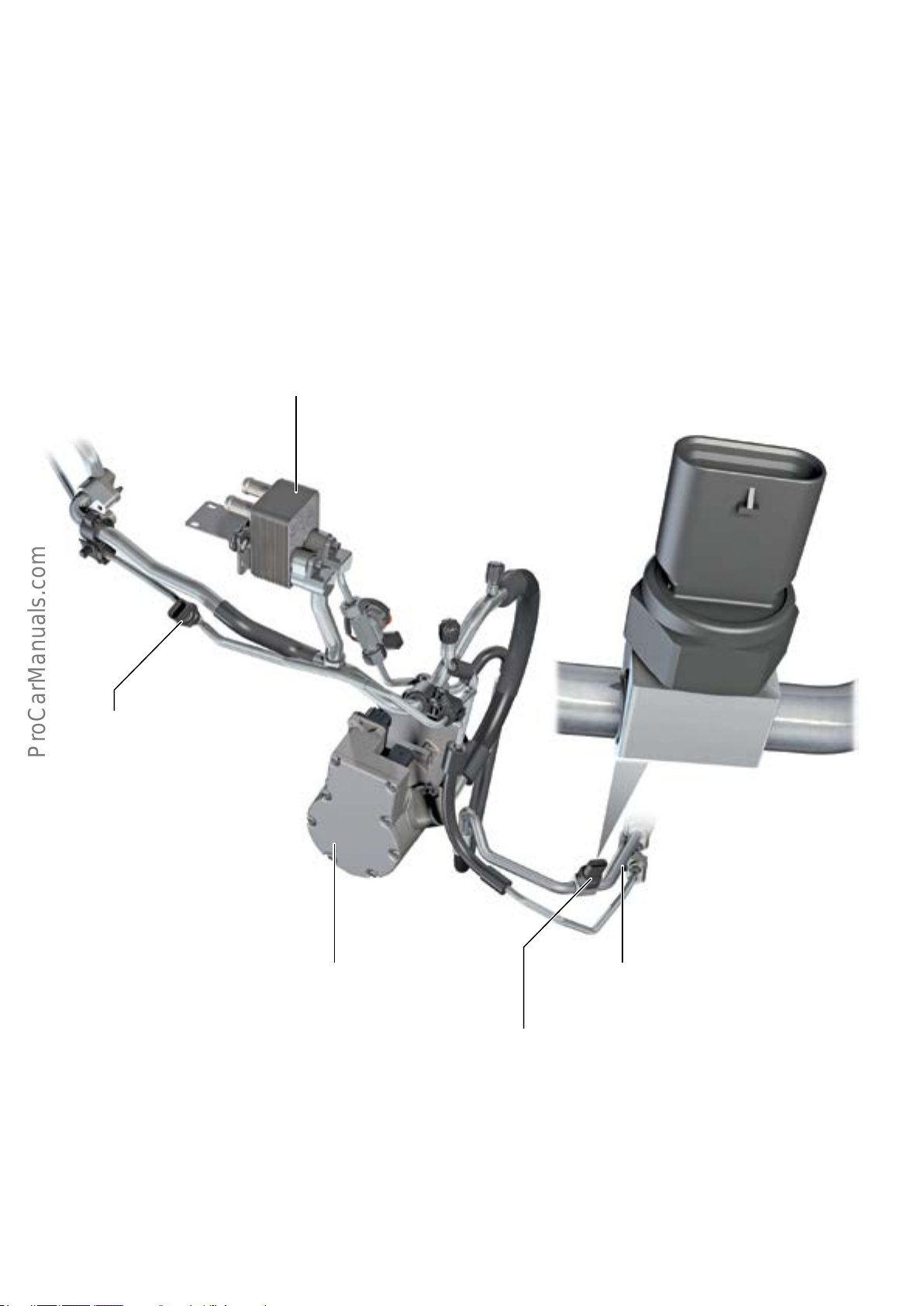
Refrigerant pressure sensor
In vehicles for the North American market, A/C Refrigerant
Pressure/Temperature Sensor G395 is installed in place of
Refrigerant Circuit Pressure Sensor G805. This is to comply
with OBD II compatibility requirements. It is located
directly in the refrigerant ow. The refrigerant system must
be evacuated before the sensor can be removed.
High voltage battery heat exchanger
(cooler)
Refrigerant Circuit Pressure Sensor
G805
(ECE variant)
627_015
Refrigerant lineElectrical A/C Compressor
V470
A/C Pressure/Temperature Sensor
G395
(NAR variant)
52
Page 57
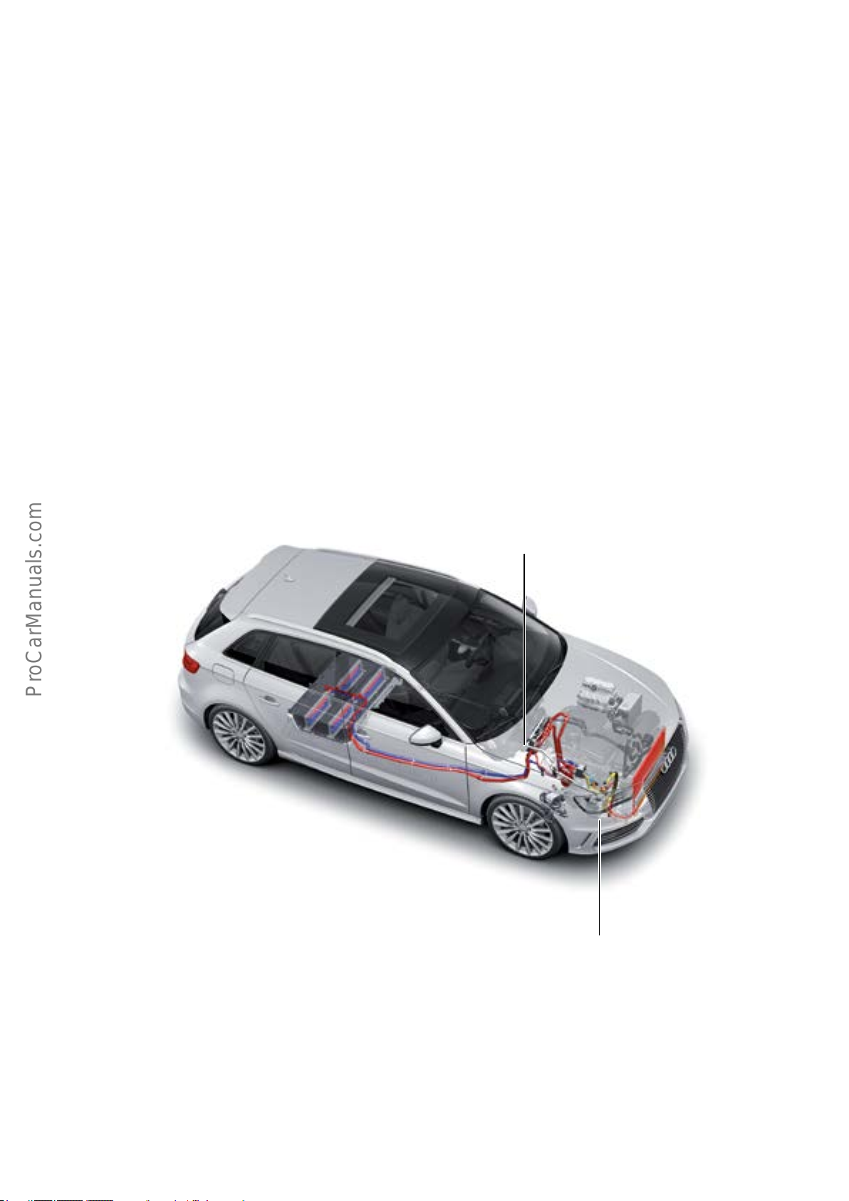
Stationary HVAC
On the AudiA3Sportbacke-tron, the stationary HVAC can be
selected via the MMI or using a smartphone app.
The following vehicle components can be used for stationary
HVAC:
• Electrical AC compressor V470.
• High Voltage heater (PTC) Z115.
Conditions for operation of the stationary HVAC system
• The stationary HVAC system can be programmed and
started by the MMI or using the smartphone app.
• The stationary HVAC system has the capacity to cool the
vehicle using the Electrical A/C Compressor V470 at high
temperatures.
• Stationary HVAC is only possible if Hybrid Battery Unit
AX1 is suciently charged and if there is enough fuel in
the fuel tank.
• The stationary HVAC also has the ability to warm the
vehicle using the high voltage heater (PTC) Z115.
High Voltage Heater (PTC)
Z115
Electrical AC compressor
V470
627_008
53
Page 58
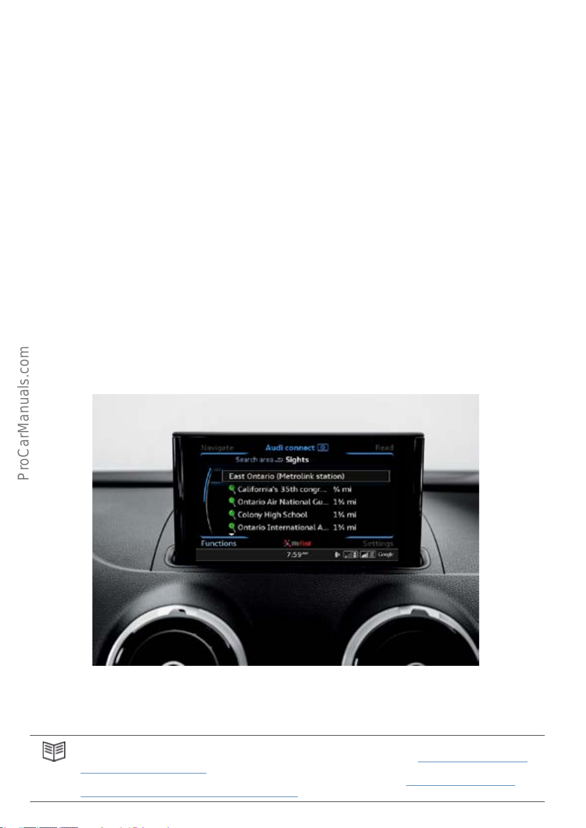
Infotainment
The 2016 A3 Sportback e-tron is equipped with the
Modular Infotainment Platform (MIB).
The A3 Sportback e-tron also has Control Module for Emergency Call Module and Communication Unit J949. The
module (also referred to as the Online Connectivity Unit
[OCU]) facilitates communication between the customer
and the vehicle when it is parked. It operates separately
from Audi connect services.
Overview of versions
The AudiA3Sportbacke-tron is available with 2versions of
the information/entertainment system. It comes with the
MMI radio as standard. The technical designation for this is
MIB Standard. MMINavigationplus is optional. This technical designation for this is MIB High.
The table on the following page shows the key standard
and optional equipment features.
54
627_092
MMINavigationpluswithAudiconnect
Reference
For more information about the information/entertainment system of the AudiA3, refer to eSelf Study Program 990143
"The 2015 Audi A3 Introduction".
For further information about the Modular Information/Entertainment System, refer to eSelf Study Program 970143
"The 2015 Audi A3 Modular Infotainment Platform (MIB)".
Page 59
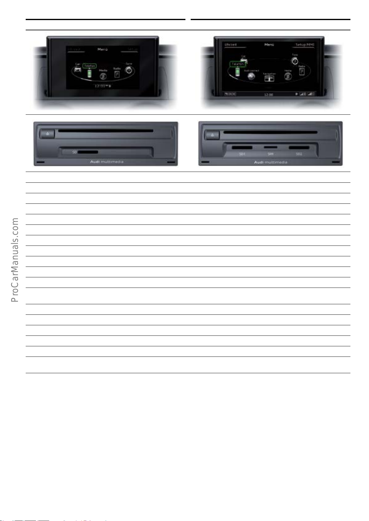
MMI Radio MMI Navigation plus with Audi conncet
Standard equipment
5.8“ TFT colour monitor with a resolution of 400x240pixels 7.0“ TFT colour monitor with 800x480pixel resolution
3D hard drive navigation system
MMI touch
AM/FM radio with phase diversity AM/FM radio with phase diversity and background tuner
Car menu Car menu
CD drive (MP3, WMA, AAC) DVD drive (audio/video, MP3, AAC, WMA, MPEG4)
1SD card reader (SDHX up to 32GB) 2SD card reader (SDHX up to 32GB)
approx. 11 GB for jukebox
Audi music interface
Audi Sound System Audi sound system
Bluetooth interface with speech dialogue system
and audio streaming
Premium interactive voice control system Premium interactive voice control system
Audi connect e-tron services Audi connect e-tron services
Sirius Sirius
Optional equipment
Audi music interface Bang & Olufsen Sound System
Bluetooth interface with speech dialogue system
and audio streaming
Standard on Prestige, optional on Premium Plus
55
Page 60
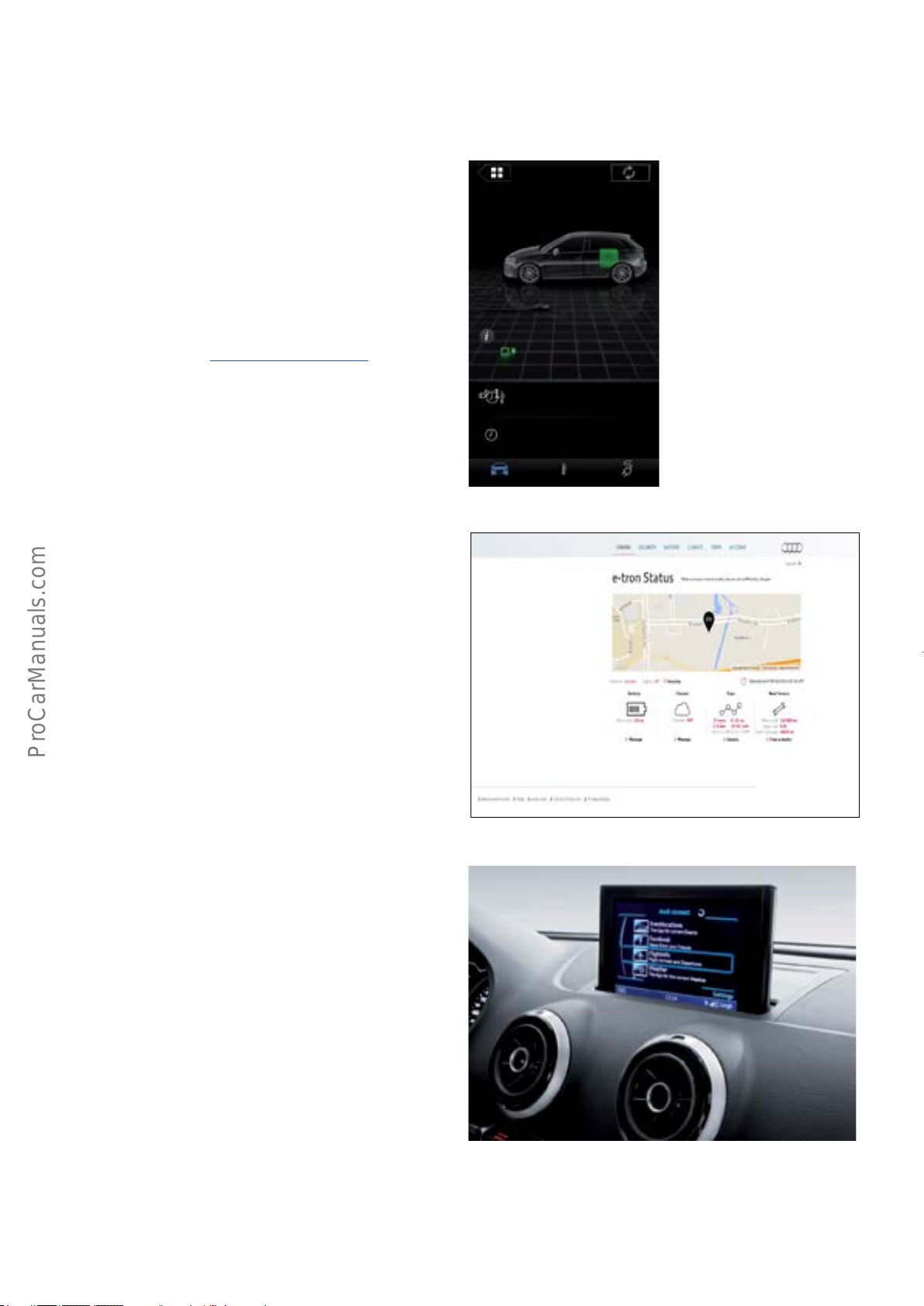
Audi connect
The term Audi connect embraces applications and developments which allow media to be used in the vehicle and to
be connected to the outside world.
Audi connect e-tron services
Audi has developed special connect services for the e-tron.
They allow specic information to be retrieved by smart-
phone and web portal as well as individual functions to be
controlled by a smartphone. These services are available as
standard in the AudiA3Sportbacke-tron and have to be
activated by the customer.
This information can be retrieved via a smartphone app and
the A3e-tron website @ www.etron.audiusa.com. Data on
vehicle status can be retrieved. This includes current state
of charge, remaining electrical range and vehicle location.
Information on recent trips, such as average electrical
consumption, is also available.
The charging cycle and the air conditioning system can be
started immediately by the app or after a specied time
has elapsed (using a customizable departure timer), allow-
ing the user to ensure that the vehicle is charged up and
optimally pre-conditioned before driving. The combination
of charging cycle and preconditioning enable the vehicle to
retain its full electrical range. If the vehicle is ready for
charging, the power required to cool or heat the passenger
compartment is drawn from the wall plug without discharging the vehicle's high voltage battery.
e-Manager
Charging plug is not inserted
12km
Next charging timer nished:
No timer activated
Next auxiliary heater/AC timer nished:
No timer activated
AC ChargingStatus
9min ago
627_087
Control Module for Emergency Call Module and Communication Unit J949 acts as the interface between the vehicle and
the smartphone or e-tron platform.
Audi connect
Other Audi connect services can be used if the vehicle is
equipped with Audi MMI Navigation plus and Audi connect.
627_086a
56
Audi connect
627_088
Page 61
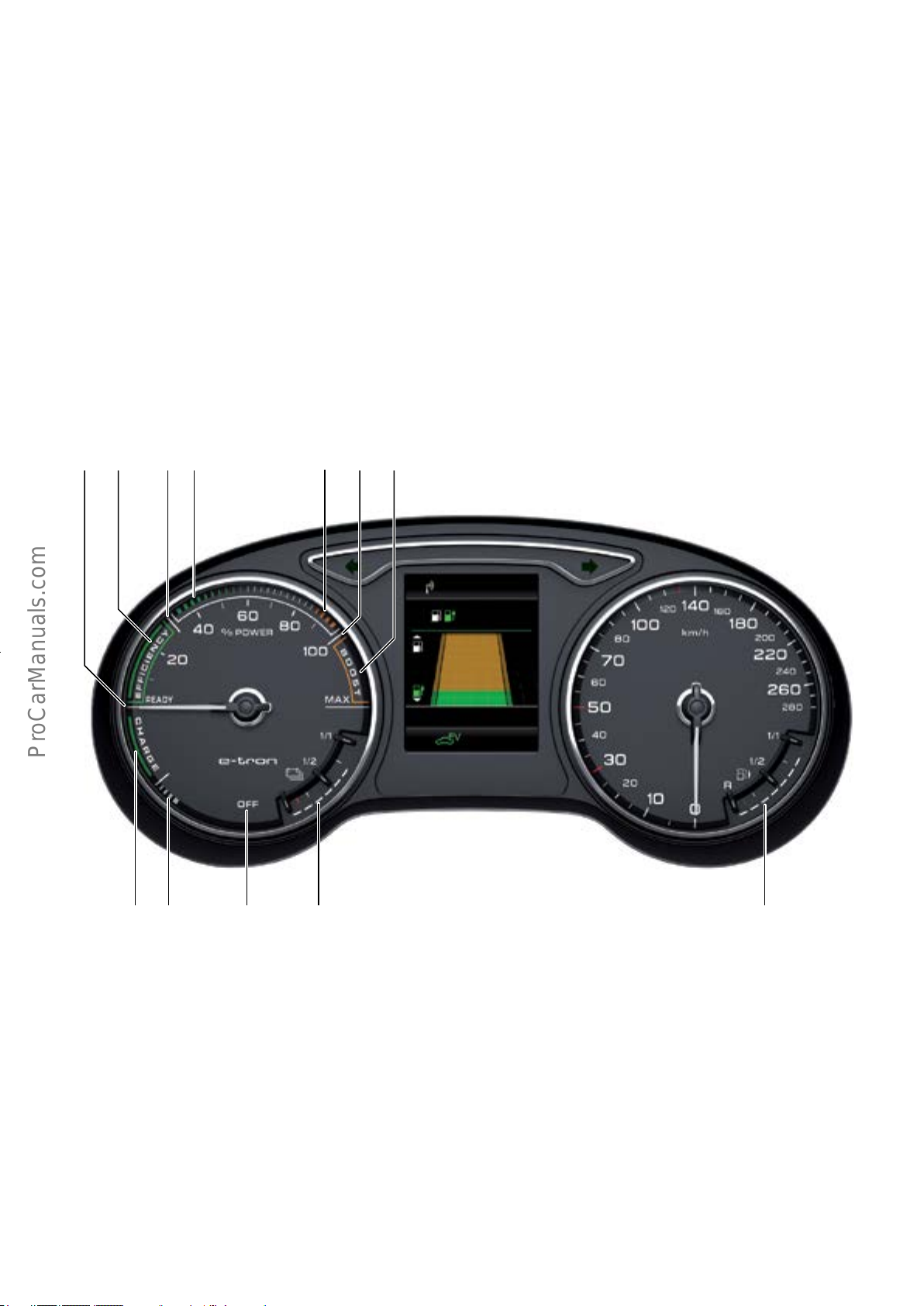
Display elements for driving in hybrid mode
The AudiA3Sportbacke-tron uses the following compo-
nents to indicate that it is running in hybrid mode:
• Power meter instead of a tachometer.
• Special display in the instrument cluster.
• Animated display on MMI screen.
• High voltage battery charge indicator instead of coolant
temperature display.
Displays in power meter
The power meter displays various vehicle operating states
and the power output or charging capacity of the hybrid
system during the trip.
1 765432
9101112
European instrument cluster shown in illustration
Key:
1 Vehicle ready "Hybrid Ready", "Terminal 15 on" and "Enable
terminal 50 on" depending on the enabling conditions
2 Electric driving (engine starting is possible) or hybrid driving
3 Threshold for EV mode
4 Economical driving (partial throttle range)
5 Full throttle range
6 Internal combustion engine 100%
Sender 1
635km
600km
35km
2027 97.0
km
D1 +22.5
7 Electric drive motor provides assistance in addition to
8 Fuel gauge
9 Charge level of high voltage battery
10 Terminal 15 o or terminal 15 on and terminal 50 o
11 Hydraulic braking in addition to electrical braking
12 Energy recovery by recuperation (under braking and accel-
°C
627_048
8
maximum engine torque (boost)
eration)
57
Page 62
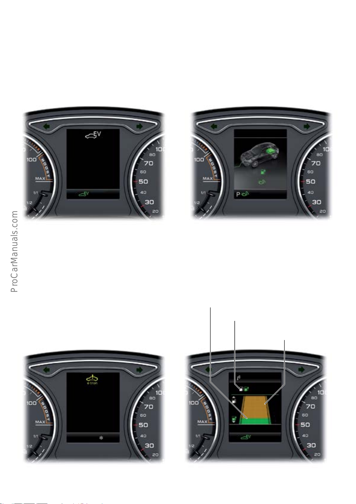
Displays in the instrument cluster
The driver can see the energy ow within the high voltage
system.
Status of the hybrid system
The messages displayed in the dash panel insert and/or
MMI display can be used for this purpose.
Charging cycle display
EV mode is activated. Information on range of high voltage battery charge and
charging duration.
Sender 1
e-tron mode:
EV
activated
D7 0/0
50km
02:14 h
+21.5
°C
(European instrument cluster shown in illustration)
(European instrument cluster shown in illustration)
Information on the hybrid system Range display
A system malfunction has occurred and the driver is
prompted to take the vehicle in for servicing.
The range of the electric motor and the internal combustion engine are displayed.
Range with electric motor
Drive:
system malfunction!
Please take vehicle
in for servicing
627_062627_061
Total range
Range with
internal combustion engine
Sender 1
720km
670km
50km
–10
(European instrument cluster shown in illustration)
58
2004 77.0
°C
627_063
(European instrument cluster shown in illustration)
D1 +21.5
km
°C
627_049
Page 63
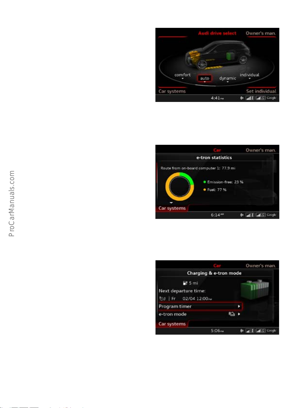
Displays on the MMI screen
Energyowdisplay
The energy ow is indicated to the driver on the screen.
e-tron statistics
The driver can call up the e-tron statistics on the display.
627_050a
"Emission-free:"
• distance covered with zero emissions
(electric + coasting + recuperation)
"Fuel type:"
• distance covered with the internal combustion engine
Statistics can be displayed for actual trip and total distance
covered. The current display is dependent on the onboard
computer.
Charging and e-tron mode
The driver can view the settings.
12:00
627_064a
627_065b
59
Page 64
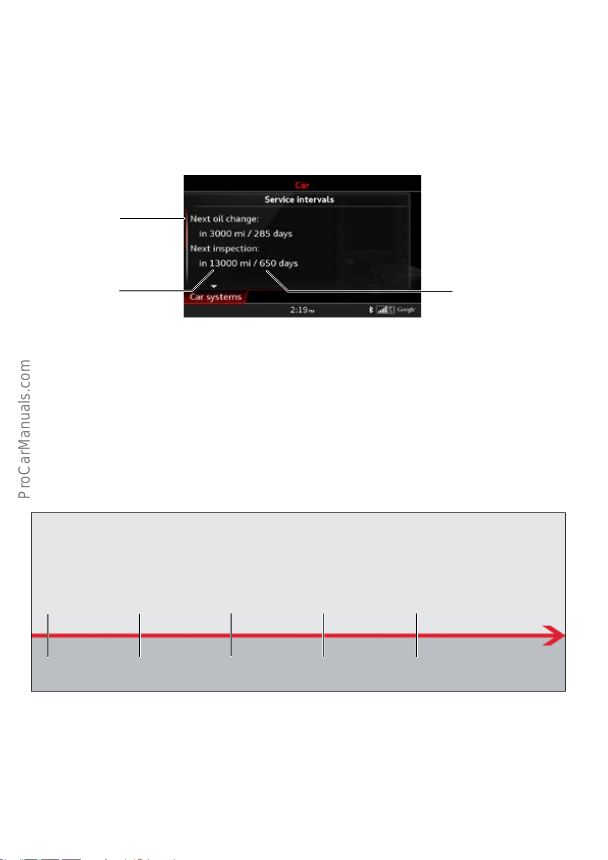
Service
Service interval overview for North American region
Service recommendations can be viewed through the MMI.
• Oil change service.
• Mileage based service events.
• Time based service events.
Flexible service event
Mileage based service event
(ROW)
Overview of maintenance intervals for vehicles in the USA
Time based service event
625_073a
The AudiA3Sportbacke-tron is generally subject to xed
inspection and maintenance intervals in the US market.
The value indicated for the next oil change is 5,000 miles /
365days for new vehicles. The next oil change after this is
set at 10,000 miles / 365 days.
Oil change service
5000miles /
1 year
Inspection with oil change
15,000miles /
2 years
Oil change service
25,000miles /
3 years
The value for the next inspection is 15,000 miles / 730
days for new vehicles. The next inspection after this is done
together with the oil change at 20,000 miles / 730 days.
Inspection with oil change
35,000miles /
4 years
Oil change service
45,000miles /
5 years
60
627_018
Page 65

Frequently Asked Questions (FAQs)
Extreme care should be taken when working on hybrid vehicles. You must always follow relevant regulations and guidelines.
This information will help you recognize hazards, enabling you to respond promptly and correctly in the event of an accident.
Q: Can the 2016 Audi A3 Sportback e-tron be washed in an
automatic car wash?
A: Yes, the 2016 Audi A3 Sportback e-tron can be washed in
an automatic car wash without any special restrictions.
Q: Can you perform an engine wash on the 2016 Audi A3
Sportback e-tron?
A: You can perform an engine wash on the 2016 Audi A3
Sportback e-tron as long as you observe accepted environ-
mental rules. If using a high pressure sprayer, do not aim it
directly at high voltage components.
Q: What should I do if the vehicle needs to be towed?
A: The vehicle should be transported by at bed towing. If
this is not possible, it must be at towed (front or rear axles
must not be raised) and a towing speed of 31 mph (50
km/h) must not be exceeded.
Q: Can the 2016 Audi A3 Sportback e-tron be driven
without a high voltage battery?
A: Any malfunction in the high voltage battery will trigger
dened error mechanisms in the system. In the event of a
more serious defect, the high voltage system will usually
shut down. If this happens, the vehicle can only be driven
until the 12V battery is discharged.
Q: What additional tasks should be performed as part of
PDI?
A: No additional preparations are needed for high voltage
components during the PDI of the 2016 Audi A3 Sportback
e-tron. In transport mode, the electric motor is used solely
as a generator, which means that electric driving, boost,
start-stop, and recuperation are not possible. In this mode,
the high voltage battery is continually charged as long as
the combustion engine is running.
Q: What needs to be kept in mind when the 2016 Audi A3
Sportback e-tron is parked or stored?
A: Please refer to the standard checklist for vehicles in
stock and in storage. This list describes what activities need
to be carried out and when.
Q: What should be done in the event of an accident?
A: First, either someone in the car or a rescue worker
should switch OFF the ignition. This process is the same as
in any Audi vehicle. The high voltage system in the 2016
Audi A3 Sportback e-tron is automatically shut down when
the belt tensioners or airbags are activated. There is no
need for emergency responders to isolate it. Details are
provided in a separate manual for emergency services.
Q: What type of voltage and current are there in the high
voltage system of the 2016 Audi A3 Sportback e-tron?
Q: What do I need to know about raising the vehicle on a
car lift, wheel alignment platform, or brake test platform?
A: There are no special instructions for the 2016 Audi A3
Sportback e-tron that dier from the standard Audi Q5.
Important: if the ignition is switched ON, the combustion
engine may start.
Q: Does the customer require special training for the 2016
Audi A3 Sportback e-tron?
A: The customer does not need any special training.
However, the information in the owner’s manual specic to
hybrid technology should be noted.
Q: What service work can be done by the customer?
A: All non-high voltage system service work can be done by
the customer, as with any other Audi vehicle. However,
work on the high voltage system should only be done by a
trained high voltage technician at an authorized service
center in accordance with Audi guidelines.
A: When the high voltage system is active, direct current
(DC) voltage ows through the electric A/C compressor,
high voltage battery, and power electronics. The electric
motor operates with alternating current (AC) voltage. An
extra capacitor is tted in the power electronics to serve as
a power reserve. This capacitor is discharged when the
ignition is switched OFF.
Q: What levels of voltage and currents are dangerous?
A: Alternating voltage of 25V or above and direct voltage of
60V or above are dangerous. Maximum contact voltage
must not exceed 50V for alternating current (AC) voltage or
120V for direct current (DC) voltage. A current of approximately 5mA or more can be recognized by the human body,
with a current of approximately 10mA or more representing a serious safety hazard.
61
Page 66

Q:Whataretheeectsofalternatingcurrent(AC)and
direct current (DC) if a person comes in direct bodily
contact with these currents?
A: Alternating current (AC): Direct contact with this current
will add a harmful disruptive electrical current to the
human body that can trigger involuntary vibrations in the
muscles and heart. The lower the frequency, the more
dangerous the voltage. Ventricular brillation (heartbeat
alteration and/or heart stoppage) can result. Without
prompt rst aid, this can prove fatal. Direct current (DC):
Direct contact with this current can break down (liquefy)
body tissues through electrolytic dissolution, resulting in
tissue poisoning. This damage will only be noticeable
several days after the DC direct contact, and if left
untreated, can be fatal.
Q:Whataretheeectsandaftereectsofelectrical
accidents?
A:Shockeect: Risk of injury from uncontrolled movements and loss of balance.
Thermaleect: Burns and carbonizations at the entry and
exit points of the current, as well as internal burns. Resulting stress to the kidneys may be fatal.
Q:Whatrstaidshouldbegivenfollowinganelectrical
accident?
A: If the person is verbally unresponsive:
1. Check pulse and breathing.
2. Call 911 or arrange for someone else to make the
call without delay.
3. Perform articial respiration and CPR until EMS
arrives.
4. If it appears that the person has stopped breathing
or their heart is in distress, use an automated exter-
nal debrillator (AED) to quickly diagnose and treat
them. AEDs are simple to use, with their proper use
taught in rst aid and CPR classes.
The AED will only supply a shock to the patient if it
detects an abnormal or no heartbeat, and can
return the patient to a normal heartbeat. Even
when the AED is successful, the patient should still
be treated by a rst responder team.
If the person is verbally responsive:
1. Cool any burns and cover with a sterile lintfree
dressing.
2. The person must be examined by a doctor to help
prevent after eects.
Chemicaleect: Blood and cell uids are broken down by
electrolysis. The result is serious poisoning that becomes
noticeable after several days
Eectonmuscles: Muscle contractions and impairment of
controlling brain functions. Consequences may include loss
of movement, contraction of the lung muscles (breathing
stops), and arrhythmia (ventricular brillation, heart stops
pumping).
Q: What should I do if a person is touching and/ or is in
direct contact with electrical voltage?
A: It is important to follow these instructions:
1. Consider your own safety rst.
2. Do not touch someone who is in direct contact with
electrical voltage.
3. If possible, de-energize the electrical system.
Immediately switch OFF the vehicle’s ignition or
unplug the service connector for the high voltage
system.
4. Separate the person or electrical conductor from
the power source with a non-conductive object (for
example, a wooden plank or broom handle).
Q: What should I do in the event of an accident involving
batteries or battery contents?
A: It is important to follow these instructions:
1. If skin contact occurs, rinse well with water.
2. In the case of gas inhalation, move the person to
fresh air.
3. If eye contact occurs, rinse with plenty of water (for
at least 10 minutes).
4. If battery contents are swallowed, the person
should drink plenty of water, but not so much that
vomiting is induced.
5. Seek medical treatment.
62
Page 67

Notes
63
Page 68
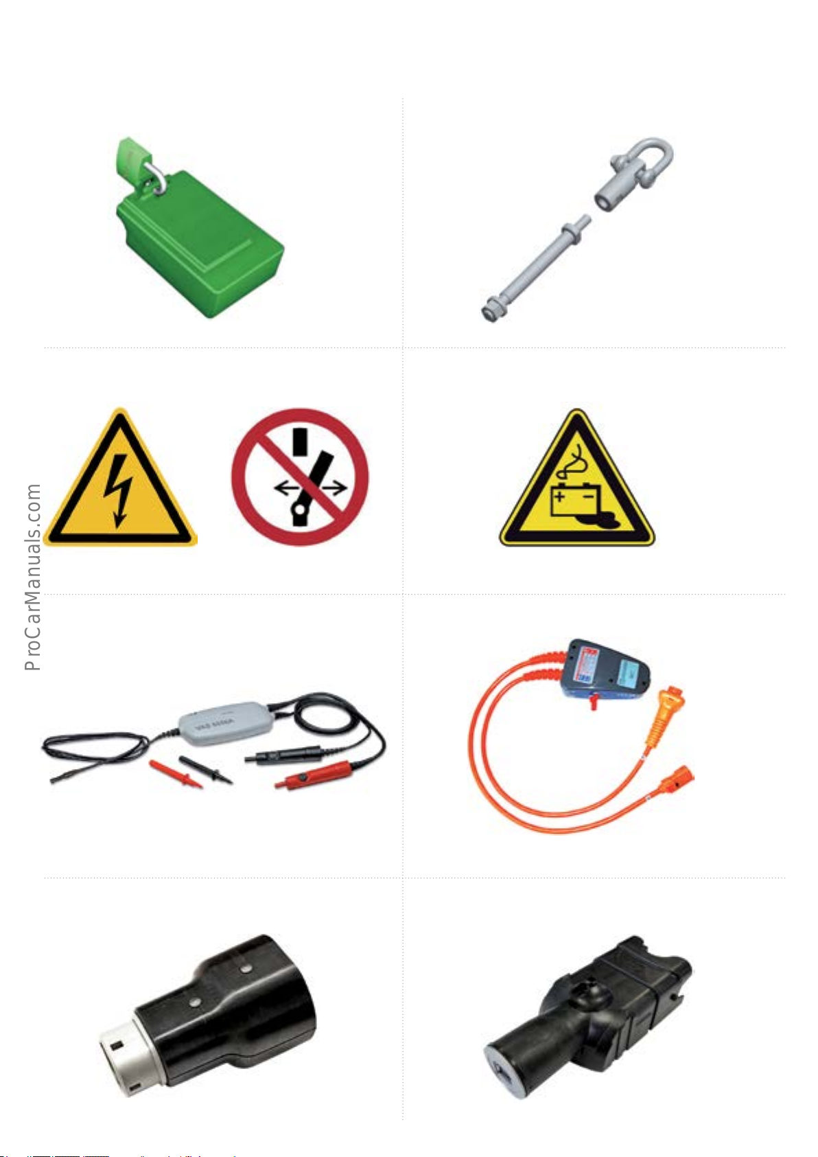
Special tools and workshop equipment
Special tools
Locking cap T40262 Adaptor for workhop crane T10542
627_067 627_068
Workshop equipment
Hybrid warning labels
Warning label for high voltage batteries
LightningashVAS6649 VAS 6786
627_069 627_070
HighvoltagetestingmoduleVAS6558A
SwitchVAS6650A
HighvoltagetestadaptorVAS6558/9-6
627_071
High voltage test adaptor for charging socket
VAS6558/10-1
(Europe)
USB adaptor for e-tron charging system
627_081
627_072
627_075
64
627_076
Page 69
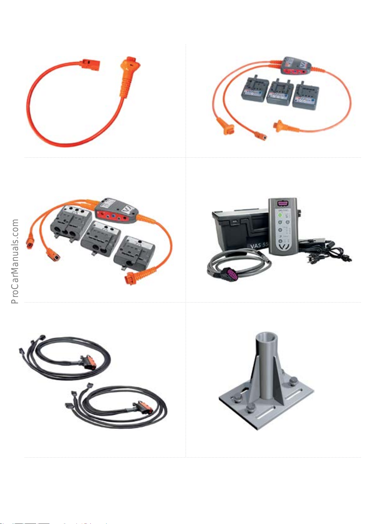
HighvoltagetestadaptorVAS6558/9-5
HighvoltagetestadaptorVAS6558/9
627_073
HighvoltagetestadaptorVAS6558/15
627_077
Test adaptor VAS 6606/10
627_074
HighvoltagediagnosticsboxVAS5581
627_078
Assembly platform support for engine bracket
VAS6131/16-4
627_079
Other workshop equipment is as follows:
• AC ushing adaptor, high pressure VAS6338/40.
• AC ushing adaptor, low pressure VAS6338/41.
627_080
65
Page 70
Self-study programs
For more information please refer to the following Self-study programs.
Self-Study Program 990123
Audi Q5 hybrid quattro
eSelf Study Program 920253
The Audi 1.4l TFSI Engine
SSP 990123
Audi Q5 Hybrid quattro
SSP 920253
The Audi 1.4l TFSI Engine
i
eSelf Study Program 990143
The 2015 Audi A3 Introduction
eSelf Study Program 970143
Modular Infotainment Platform (MIB)
SSP990143
The 2015 Audi A3 Introduction
SSP 970143
Modular Infotainment Platform
(MIB)
eSelf Study Program 970343
The 2015 Audi A3 Vehicle Electronics
and Driver Assistance Systems
SSP970343
The 2015 Audi A3
Vehicle Electronics and Driver
Assistance Systems
2
eSelf Study Program 970243
The 2015 Audi A3Onboard Power Supply
and Networking Systems
•The Self Study Programme teaches a basic knowledge of the design and functions of new models, new
automotive components or new technologies.
It is not a Repair Manual! Figures are given for explanatory purposes only and refer to the data valid at the
time of preparation of the SSP.
For further information about maintenance and repair work, always refer to the current technical literature.
eSelf Study Program 960143
The 2015 Audi A3
Running Gear and Suspension System
Note
SSP970243
The 2015 Audi A3 Onboard Power
Supply and Networking Systems
2
SSP960143
The 2015 Audi A3 Running Gear
and Suspension System
66
Page 71

Knowledge assessment
An On-Line Knowledge Assessment (exam) is Available for this eSelf-Study Program.
The Knowledge Assessment is required for Certication credit.
You can nd this Knowledge Assessment at:
www.accessaudi.com
From the accessaudi.com Homepage:
• Click on the “ACADEMY” tab
• Click on the “Academy site” link
• Click on the Course Catalog Search and select “970253 - The 2016 Audi Sportback e-tron”
Please submit any questions or inquiries via the Academy CRC Online Support Form
which is located under the “Support” tab or the “Contact Us” tab of the Academy CRC.
Thank you for reading this eSelf-Study Program and taking the assessment.
67
Page 72
970253
All rights reserved.
Technical specications are
subject to change without notice.
Audi of America, LLC
2200 Ferdinand Porsche Drive
Herndon, VA 20171
68
 Loading...