

Page 1
PROGRAMMABLE THREE-WAY SWITCH
MODEL TI054A-06-3W
FOR ALL LIGHTING SYSTEMS
MAXIMUM CHARGE MUST NOT EXCEED 500 W / 230 V
The TI054A-06-3W three-way switch MAY be installed on EITHER of the
following lighting systems:
- Incandescent
- Halogen
- Low voltage halogen with transformer
- Fluorescent
It must not be installed on a motor or a charge exceeding 500 W.
INSTALLATION
This programmable switch may be used in either a single pole or a multiple pole switch installation.
Multiple pole switch installations with an electronic switch are different
from conventional installations. Read the wiring instructions carefully
and select the one that applies to your situation.
ou must follow the steps in the indicated order at all times:
Y
Note: Please note that the two (2) “C” terminals on the programmable
switch have no polarity. They can both be used indiscriminately.
1. Cut the power supply at the main circuit breaker in order to avoid the
risk of electrical shock.
2. Remove and disconnect all existing three-way or regular switches. In
the case of a three-way switch, identify the wire connected to the “C”
or “common” terminal.
3. Connect each wire, as it is disconnected, to the programmable
switch following the appropriate wiring diagram.
4. Close the main circuit breaker to reinstate the power supply.
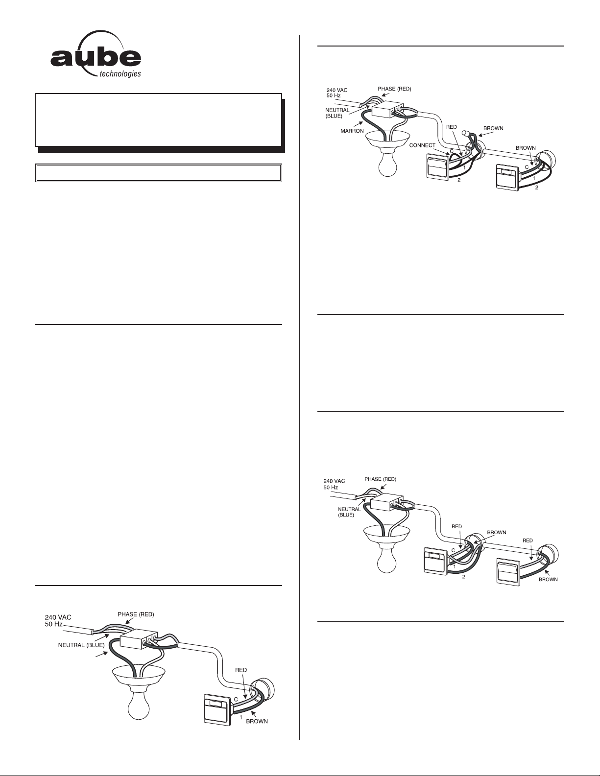
FOR AN EXISTING THREE-WAY SWITCH INSTALLATION
To replace a conventional three-way switch by a programmable one,
follow the following wiring diagram:
The “common” wire (phase) that you identified while removing the
existing three-way switch must be connected to one of the two “C” terminals on the programmable switch. Connect the other two wires
(black) to the remaining two terminals on the programmable switch.
The connecting wire supplied will be added to the remote three-way
switch between the “common” terminal and the black wire connected to
terminal “C” on the programmable switch. Once the connection is completed, correctly install the switches in their own electrical box and
close the main circuit breaker to reinstate the power supply.
FUNCTION CHECK
Refer to the “START-UP” section to start the programmable switch. Try
to activate the lighting using the remote switch and the programmable
switch. If everything is in working order, the installation is complete.
Otherwise, cut the power supply at the main circuit breaker and reconnect the connecting wire on the remote switch between the “common”
terminal and the other terminal.
FOR A NEW THREE-WAY INSTALLATION
For a new installation, you may use a single pole switch at the remote
location. Use the following wiring diagram:
Note: Note that the connecting wire supplied is not used in this installation.
FOR A SINGLE POLE INSTALLATION
For a single pole installation no wire is connected to terminal “1”.
START-UP
For the first trial under power, use a paper clip to push on the R button.
You should see the figures 0:00 flashing on the screen.
If nothing appears on the screen, check the following points:
a) The programmable switch fuse may not be installed properly or may
be defective.
b) If the programmable switch controls a lamp with its own switch,
make sure that the latter is always “ON”.
920-054-001-00-1-0 1/3
Page 2
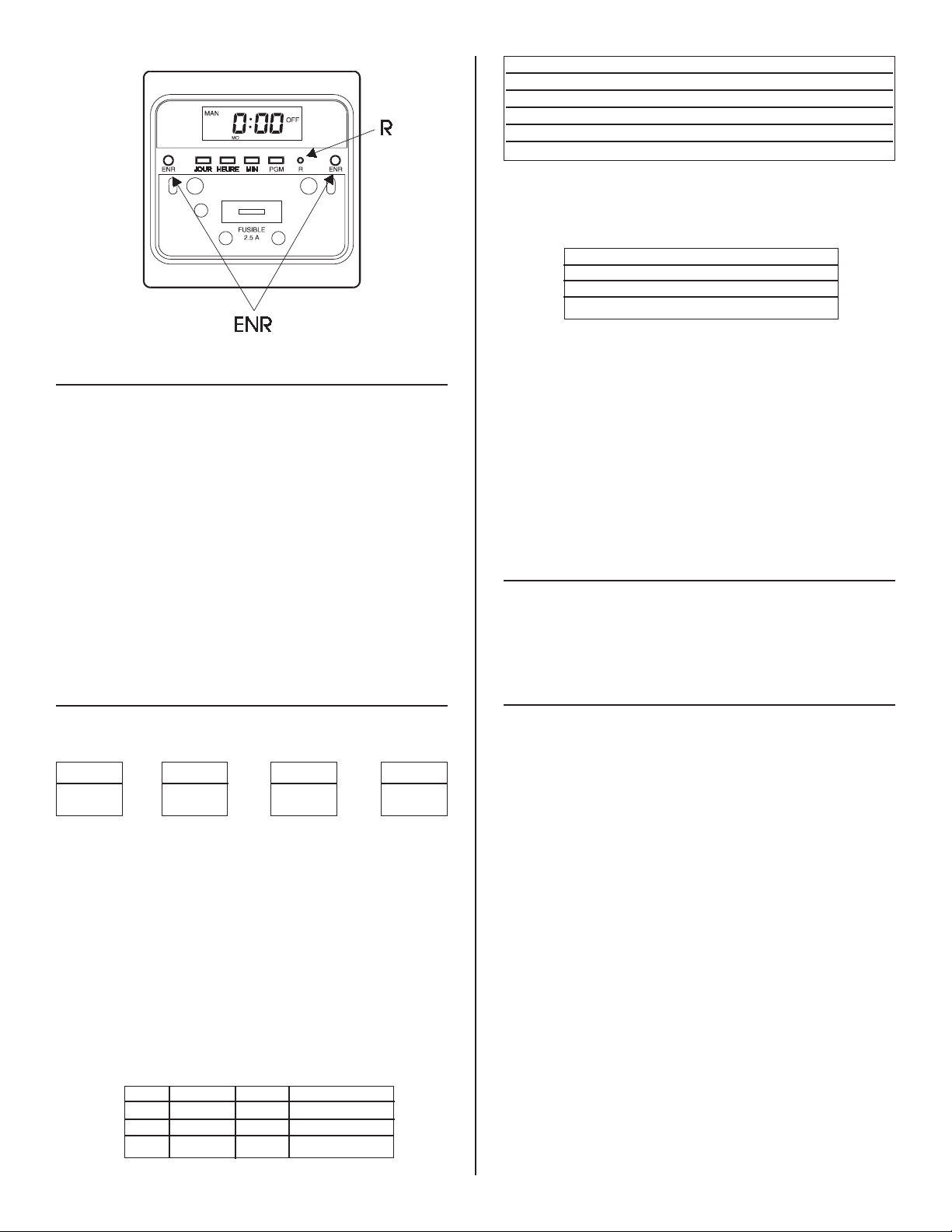
OPERATING MODES
The programmable switch offers two operating modes: MANUAL and
AUTOMATIC.
In MANUAL mode, it operates as a conventional switch. You can then
turn the light “OFF” or “ON” by pressing on the door. The screen displays “MAN” and the status of the light (“ON” or “OFF”).
In AUTOMATIC mode, the switch runs the recorded program. To activate this mode, press on the door (approximately 3 seconds) until
“AUTO” is displayed. The screen displays the active program number
as well as its “ON” or “OFF” status.
To temporarily override the programming, simply press on the door.
The new status of the light flashes to indicate that this status is temporary.
To exit the “AUTO” mode, press on the door (approximately 3 seconds)
until “MAN” is displayed.
January 0 July 181
February 31 August 212
March 59 September 243
April 90 October 273
May 120 November 304
June 151 December 334
3) nor/Ad : Does your country use daylight saving time (advanced
time) in the summer? If so, in which period of the year are you?
Ex. : In France, on June 24th, we are in daylight saving time (Ad).
nor/Ad = Ad
P1 ON 20:38 Sundown
P1 OFF 22:00
P2 ON 5:00
P2 OFF 5:10 Sunrise
LC: Does your country follow the rules of the standard time according
to its position in relation to Greenwich or has it set the time in a more
practical way?
Since this programmable switch can be used anywhere in the world, it
is based on the universal time (24 time zones, each increasing by one
hour toward the East starting at Greenwich). For practical reasons however, some time zones have been redefined (in order to respect a frontier or for reasons of economy).
In this case, to remain compatible with the universal time, you need to
enter a local correction factor.
Ex:Since the second world war, France has adopted Central European
time (GMT+1). Thus, its local correction factor will be:
LC = 1
SETTING THE TIME
1. Lift the lower side of the door with a flat screwdriver.
2. Set the time by pressing on the HOUR and MIN buttons.
3. Press on one of the SAVE buttons to record the time and return to
the MANUAL or AUTOMATIC operating mode.
DEFINITION OF YOUR CITY’S PARAMETERS
Before programming your switch, complete the following table by
answering the questions:
Latitude Longitude DAY # nor/Ad
1) LATITUDE & LONGITUDE: What are the latitude and longitude of
your residence? Identify the city closest to yours in the table. If none
is listed in the table, this information is usually available on road
maps (latitude: horizontal lines and longitude: vertical lines).
Ex.: Paris 48,2; means Latitude 48 N and Longitude 2 E.
Note that SOUTH latitudes and WEST longitudes are indicated with a
minus sign. The maximum latitude is +/- 65º.
2) DAY # : What is the day of the year?
Add the month code (see table below) to the day’s date.
Ex.: If today is June 24th:
DAY # = 151 + 24 = 175
P1 ON 21:50 Sundown
P1 OFF --:-- free
P2 ON --:-- free
P2 OFF 5:58 Sunrise
RECORDING YOUR PARAMETERS
Now, you only need to program the parameters previously defined into
your programmable switch.
Note: If you make a mistake while entering data, select the ill-defined
parameter again using the “code” button and make the appropriate correction.
1. Press once on the CODE button.
- The screen displays “Latitude 00”.
- Use the HOUR and MIN buttons to enter your latitude.
2. Press again on the CODE button.
- The screen displays: “Longitude 000”.
- Use the HOUR and MIN buttons to enter your longitude.
3. Press again on the CODE button
- The screen displays “Day # 000”.
- Use the HOUR and MIN buttons to enter the day #.
4. Press again on the CODE button.
- The screen displays “nor” (normal).
- Use the MIN button to switch from Standard time (“nor”) to
Daylight-Saving time (“Ad”).
5. Press again on the CODE button.
- The screen displays “LC 0”.
- Use the MIN button to enter the local correction factor.
You have now completed the setting of your parameters. Press on one
of the SAVE buttons to record your parameters and return to the MANUAL or AUTOMATIC operating mode.
920-054-001-00-1-0 2/3
Page 3

DEFINING YOUR PROGRAMS
LAT LONG
ATHENS
GREECE
37 23
39 22
1- This switch can memorize 2 “ON/OFF” programs which repeat
themselves every day.
If you have entered your city’s parameters, the programs “P1 ON” and
“P2 OFF” represent sundown and sunrise hours. Our example shows
these results.
If your switch is set at “AUTO”, your lights will go on at sundown and go
off at sunrise.
2- If you wish your lights to go on at sundown but go off for example at
23:00, enter program “P1 OFF - 23:00”.
Furthermore, if you wish your lights to go back on at 5:00 AM and go
off at sunrise, enter program “P2 ON - 5:00”
nor - Standard time
- Winter time
Ad - Daylight-saving time
- Summer time
Note that the “P1 OFF” and “P2 OFF” programs have priority on the “P1
ON” and “P2 ON” programs respectively.
If, for example, the sun rises at 4:58 (“P2 OFF”) and you request in “P2
ON” that the lights go on at 5:00, the lights will not go on that morning.
If you wish to replace the “sundown” and/or “sunrise” programs by a
3-
fixed hour
parameters using the HOUR and MIN buttons.
, select the “P1 ON” or “P2 OFF” programs and enter new
SAVING YOUR PROGRAMS
1- Press on the PGM button to select the program.
2- Use the HOUR and MIN buttons to modify the program.
3- Press on the CODE button to return to the initial value.
P1 ON = Sundown P1 OFF = -- : -P2 ON = --:-- P2 OFF = Sunrise
4- Press on the SAVE button to record your modifications and return
to the MANUAL or AUTOMATIC operating mode.
TO SWITCH FROM STANDARD TIME TO
DAYLIGHT-SA
If your country uses daylight-saving time, execute the following procedure when the time changes:
1- Press 4 times on the CODE button to select the “nor/Ad” mode.
2- Use the MIN button to switch from the “nor” (Standard) mode to the
“Ad” (Daylight-saving) mode and vice versa.
3- Press on the SA
operating mode.
The programmable switch will automatically adjust the clock and the
sundown/sunrise table for the period of the year. Y
adjust the clock manually.
VING TIME
VE button to return to the MANUAL or AUTOMATIC
ou do not need to
MEMORY PROTECTION
The programmable switch is equipped with a rechargeable battery that
will protect your program recordings during a power failure.
Note that the screen is not ON during power outage.
CHARACTERISTICS
Model: TI054A-06-3W
Supply: 240 VCA, 50 / 60 Hz
Load: 15 watts min., 500 watts max.
Approvals : CE
Storage temperature range: -20 to 50°C
Operating temperature range: 0 to 50 *C
Max. latitude : +/- 65°
Precision of the solar table: +/- 11 min. (max. error near the Poles)
WARRANTY
AUBE TECHNOLOGIES INC. ONE YEAR LIMITED WARRANTY
This product is warranted against material defects and workmanship in
normal use for a period of one year, from the date of the original purchase from authorized dealers. Warranty does not cover transportation
costs. Nor does it cover a product subjected to misuse or accidental
damage.
This limited warranty is in lieu of all other warranties, obligations or liabilities expressed or implied by the company.
In no event shall AUBE Technologies inc. be liable for consequential or
incidental damages resulting from installation of this product. Within
this period, any product proven defective in normal use will be repaired
or replaced, at AUBE's option, without charge for either parts or labour,
provided that the defective product with the original sale receipt is
returned to the original dealer or is shipped pre-paid, insured and
addressed to:
Head Office:
Aube technologies inc.
705, Montrichard 10 rue Ampère
Iberville (Quebec) 95500 Gonesse
Canada J2X 5K8 France
Tel.: (450) 358-4600 Tel.: 33 (0) 1 34 07 99 06
Fax: (450) 358-4650 Fax: 33 (0) 1 34 07 99 19
www.aubetech.com www.aubetech.com
service@aubetech.com advaube@comintes.com
Carrer Segur, 74
08035 Barcelona
España
Tel.: 34 93 420 28 73
Fax: 34 93 429 30 79
www.aubetech.com
reutor@teleline.es
920-054-001-00-1-0 3/3
 Loading...