

Page 1
Patent Pending
Operation Manual
Page 2

General Guide Notes
Document Number ANW1223
Manual Release Date August 28 2017
Firmware Version
Some features described in this manual require the latest rmware to be installed on the hardware platform. Check with ATX
Networks Technical Support for the latest release of rmware. The rmware installed on your Device may be found in the GUI.
At the time of publication of this manual the most current released rmware versions are:
Version VA2.2.1.291_VMS2.2.1.1098 Build 1098
Mkip System Menu Version 0.5.5
Organization of This Manual
This manual is generally organized based on the main function Transcoding with individual chapters dedicated to describing
the congurable features and monitoring. Further chapters outline activities related to the GUI operation and conguration.
Cross Reference Usage
Hyperlinks are used throughout the guide to assist the reader in nding related information if the reader is viewing the PDF
le directly. Hyperlinks may be identied by their blue text. Most links are to related pages within the document, but some may
reference outside documents if the reader needs that additional information. The Table of Contents is entirely hyperlinked and
bookmarks are available but the bookmark feature must be turned on in your Reader application.
Symbol Usage
Throughout the manual, some symbols are used to call the readers attention to an important point. The following symbols are
in use:
WARNING: This symbol usage will call the reader’s attention to an important operation feature of
the equipment which may be safety related or may cause a service outage.
NOTE: This symbol indicates that there is helpful related information available in this note or
elsewhere in the guide.
Although every effort has been taken to ensure the accuracy of this document it may be necessary, without notice, to make amendments or correct omissions.
Specications subject to change without notice.
VersAtive®Pro is a registered trademark of ATX in the United States and/or other countries. Products or features contained herein may be covered by one or more U.S. or foreign patents.
Adobe®, Flash®, Dolby® , Wikipedia®, and other non-ATX product and company names mentioned in this document are the property of their respective companies.
Page 3

TABLE OF CONTENTS
GENERAL GUIDE NOTES ....................................................II
1. GUI ENVIRONMENT .................................................... 1-1
1.1 Chapter Contents ................................................. 1-1
1.2 Switch and Firewall Port Opening. . . . . . . . . . . . . . . . . . . . . . . . . . . . . . . . . . . . . 1-1
1.3 Preview ......................................................... 1-2
1.4 Launch the GUI and Log in .......................................... 1-2
1.5 Conguring the Device - Quick Summary. . . . . . . . . . . . . . . . . . . . . . . . . . . . . . . 1-2
1.6 The GUI ........................................................ 1-3
1.7 Application Terminology ............................................ 1-4
1.8 Device Menu & Tool Bar ............................................ 1-4
1.9 Resource Menu & Tool Bar .......................................... 1-5
1.10 Copy & Paste .................................................... 1-6
2. GENERAL (GLOBAL) CONFIGURATION ................................... 2-1
2.1 Chapter Contents ................................................. 2-1
2.2 General Tool Bar .................................................. 2-1
2.3 General Right Click Menu ........................................... 2-1
2.4 Products Upgrade ................................................. 2-2
2.5 System Time ..................................................... 2-4
2.6 User Management ................................................ 2-4
2.7 Licence ......................................................... 2-5
2.8 SNMP .......................................................... 2-6
3. DEVICE CONFIGURATION .............................................. 3-1
3.1 Chapter Contents ................................................. 3-1
3.2 Settings and Info .................................................. 3-1
3.3 Network ......................................................... 3-2
3.4 Licence Information ............................................... 3-3
3.5 Maintenance ..................................................... 3-4
4. TRANSCODING APPLICATION ........................................... 4-1
4.1 Chapter Contents ................................................. 4-1
4.2 Ethernet Resources ............................................... 4-1
4.3 SPTS Stream Conguration ......................................... 4-4
4.4 Create an SPTS Stream ............................................ 4-6
4.5 Publish Conguration .............................................. 4-7
4.6 Publish an SPTS Stream ........................................... 4-8
4.7 Start the Stream ................................................. 4-10
5. ALARMS & EVENTS ................................................... 5-1
5.1 Chapter Contents ................................................. 5-1
5.2 Alarms .......................................................... 5-1
5.3 Events .......................................................... 5-2
5.4 Events History .................................................... 5-3
VersAtive®Pro Enhanced – Operation Manual iii
Page 4

6. MONITORING ......................................................... 6-1
6.1 Chapter Contents ................................................. 6-1
6.2 Monitoring the Device .............................................. 6-1
6.3 Preview or Monitor Resources ....................................... 6-3
6.4 Displaying Stream Information ....................................... 6-5
7. MKIP SYSTEM SHELL .................................................. 7-1
7.1 Chapter Contents ................................................. 7-1
7.2 Connect Using Monitor, Keyboard and Mouse ........................... 7-1
7.3 MKIP Shell Menu ................................................. 7-2
7.4 Menu - Display ................................................... 7-2
7.5 Menu - Set Network. ............................................... 7-3
7.6 Menu - Ping ..................................................... 7-5
7.7 Menu - TCP Dump ................................................ 7-6
7.8 Menu - Eth0 Set Default ............................................ 7-7
7.9 Menu - Date/Time ................................................. 7-7
7.10 Menu - Restart ................................................... 7-9
7.11 Menu - Shutdown ................................................. 7-9
7.12 Menu - Authentication Mode ......................................... 7-9
8. SERVICE & SUPPORT .................................................. 8-1
8.1 Contact ATX Networks ............................................. 8-1
8.2 Warranty Information .............................................. 8-1
iv VersAtive®Pro Enhanced – Operation Manual
Page 5

GENERAL CONFIGURATION
1. GUI Environment
The GUI is the Management Interface (Graphical User Interface) used to manage the VersAtive®Pro transcoder which will be
referred to as Device.
1.1 Chapter Contents
• “Switch and Firewall Port Opening”
• “Preview”
• “Launch the GUI and Log in”
• “Conguring the Device - Quick Summary”
• “The GUI”
• “Application Terminology”
• “Device Menu & Tool Bar”
• “Resource Menu & Tool Bar”
• ”Copy & Paste”
CHAPTER 1: GUI ENVIRONMENT
1.2 Switch and Firewall Port Opening
NOTE: Any Management Switch used between Devices and the Management Computer will
require the following ports to be opened both Inbound and Outbound.
Port Number Transport Protocol Description
80 TCP RTMP,
RTMPT,
HTTP
8080 TCP HTTP HTTP Communications
8111 TCP Communication
8112 UDP Communications
8113 UDP Messaging
8118 Communications
1935 TCP RTMP/E Adobe® Flash® (Previewing, Monitoring) Flash Media Server listens for
1935 UDP RTMFP Adobe Flash (Previewing, Monitoring) Flash Media Server listens for RTMFP
8443 TCP HTTPS HTTPS Communications
1.2.1 Notes on Opening Fire Wall Port 1935 for Monitoring
Some rewalls reject trafc that doesn’t use the HTTP protocol. This behavior can prevent communication over RTMP even
if port 1935 is open. Consult the documentation for the rewall to determine how to congure it to allow RTMP trafc. To use
RTMP and RTMFP, any switch or rewall between the server and clients must allow inbound and outbound trafc on port 1935.
If it is not possible to open port 1935 inbound and outbound then monitoring will not work. In this case it is best to disable
monitoring altogether within the GUI, see Figure 6-5.
The resource contains both the actual publish and the preview. When the preview can not connect the whole pipeline of the
stream will stop and retry and not publish. The events log will report “Cannot connect to RTMP server”. The resource will show
“Resource is retrying” at the events tab. Disabling ‘Preview’ will prevent events from being detected when the streams cannot
connect during monitoring.
File Upload (Licence, VersAtive Software) By default, Flash Player clients
make RTMP connections over port 1935 using TCP.
To communicate over the RTMP protocol, clients attempt to connect to ports
in the following order: 1935, 80 (RTMP), 80 (RTMPT).
RTMP/E requests on port 1935/TCP. Clients attempt to connect over ports
in the following order: 1935, 80 (RTMP), 80 (RTMPT).
requests on port 1935/UDP
VersAtive®Pro Enhanced – Operation Manual 1-1
Page 6

CHAPTER 1: GUI ENVIRONMENT
1
2
3
1.3 Preview
The Preview function which allows viewing live video of each Ethernet Resource is turned on by default, Figure 1-1, but may
be disabled at each individual Resource by unticking the Preview On box and then clicking Save.
1.4 Launch the GUI and Log in
Figure 1-1: Preview Enabled
1. Open a new tab in the web browser of your choice, Figure 1-2.
2. Enter the IP address of the Management Port; factory default 192.168.0.23
3. Login with credentials, (case sensitive): User Name: vms
Password: VMS
4. The GUI will open as shown in Figure 1-3.
Figure 1-2: GUI Login
1.5 Conguring the Device - Quick Summary
These are the key steps required to set up the Device.
1.5.1 This Chapter:
• GUI Overview
• Open the GUI and log in.
1.5.2 General Conguration Chapter
• Managing Firmware
• Managing Users
• SNMP
1.5.3 Device Conguration Chapter
• Congure Ethernet Input & Output Streaming Ports
1.5.4 Transcode Chapter
• Create Resources
1-2 VersAtive®Pro Enhanced – Operation Manual
Page 7
• Create SPTS Streams
1
2
3
4
678
5
• Create Publish Points
• Start Transcoding from the Resource icon.
1.6 The GUI
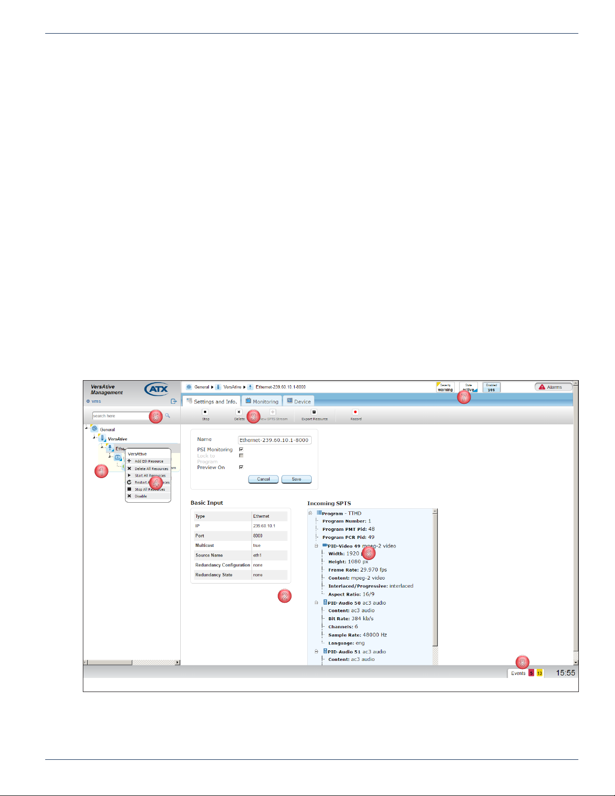
The GUI is based on a familiar Tree and Tabbed Pane design, Figure 1-3. The main parts are:
1. Tree View of Managed Elements.
2. Pane View of the Selected Element.
3. Tool Bar.
4. Context Sensitive Right Click Menu.
5. Tree View Search Tool.
6. Details View for Selected Element.
7. Alarms Notication Panel.
8. Events Notication Panel.
Managed Elements are displayed in their relationships to each other in the Tree View, see Figure 1-3, and details pertaining
to the elements are displayed in the Pane View when the element is selected. Further details about the selected element and
conguration dialogs are accessed within the Pane View with Navigation Tabs.
CHAPTER 1: GUI ENVIRONMENT
The resource will be an Ethernet IP stream address to which the Device subscribes (Devices may
have multiple physical Ethernet ports on which Resources may be present).
The Stream denes the resolution, bitrate, audio codec, and CBR/VBR for the stream. Multiple
streams may be added to the Resource.
The Publish denes the output protocol, the output IP address and interface. Multiple Publish Points
may be added to the stream.
Figure 1-3: The GUI
VersAtive®Pro Enhanced – Operation Manual 1-3
Page 8
CHAPTER 1: GUI ENVIRONMENT
1
2
345
6
7
8
9
10
1.7 Application Terminology
A review of the application terminology used in the GUI and transcoding application:
1. Resource
The external video and/or audio source content stream available to the Input Ethernet Ports.
2. SPTS Stream
The SPTS Stream denes the resolution, bitrate (constant or variable), and audio codec.
3. Publish
The Publish denes the output protocol, the output IP Address and Physical Interface.
1.8 Device Menu & Tool Bar
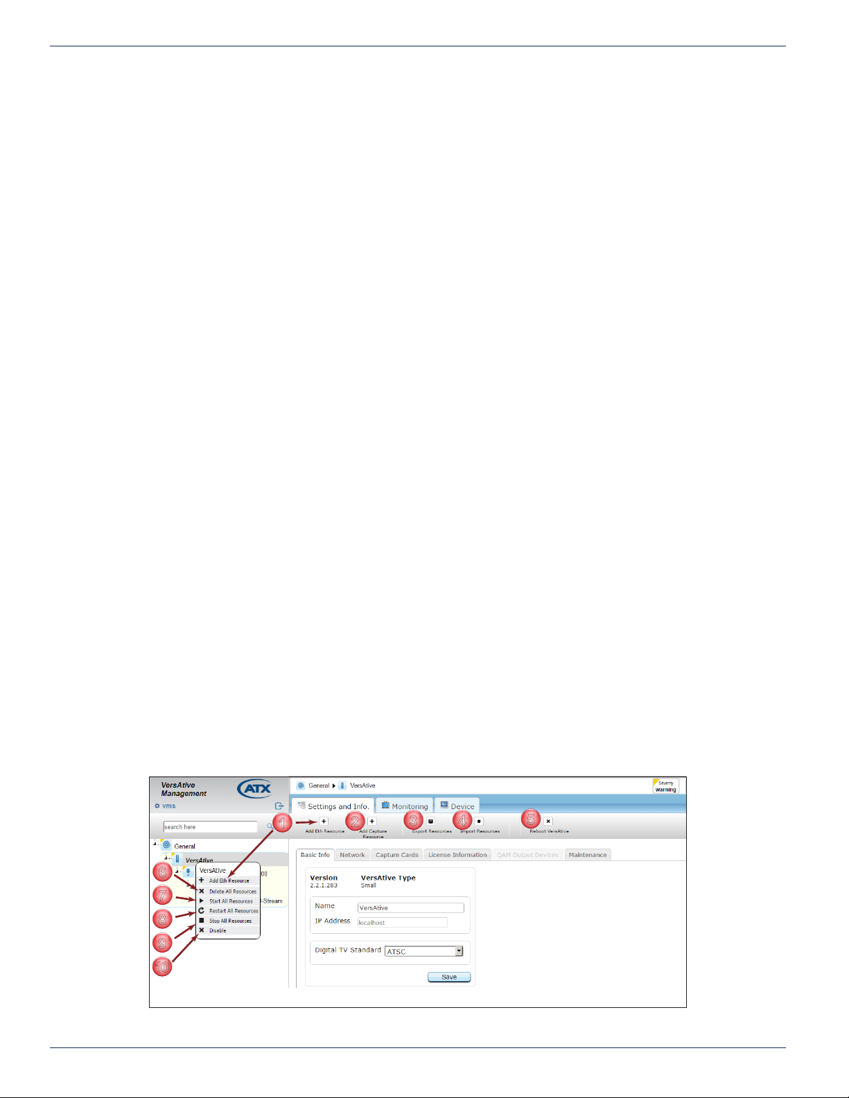
Device Conguration options are available on both the Right Click menu and the Tool Bar. To access these menus, right click
on the Device Icon (VersAtive is the Device name in this example but you may rename it) Figure 1-4.
1. Add Eth Resource
Add to this Device an Ethernet Resource for receiving content.
2. Add Capture Resource
Not used on this VersAtive Device
3. Export Resources
Saves a backup copy of the resource parameters to a le or series of les. Allows selection of any or
all of the created resources which include any SPTS streams and their publish points.
4. Import Resources
Import or restore resources from a le saved earlier.
5. Reboot VersAtive
Reboots the server.
6. Delete all Resources
May be used to stop all resources simultaneously. (Resources may also be stopped individually from
the resource itself).
7. Start all Resources
Starts all created Resources with a single command.
8. Re-start all Resources
Stops then re-starts all created Resources with a single command.
9. Stop All Resources
May be used to stop all resources simultaneously. (Resources may also be stopped individually from
the resource itself).
10. Disable
Disables the Device Platform.
Figure 1-4: Device Right Click Menu & Tool Bar
1-4 VersAtive®Pro Enhanced – Operation Manual
Page 9
1.9 Resource Menu & Tool Bar
1
2
3
456
7
8
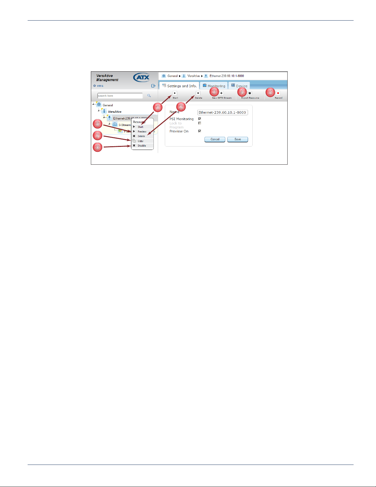
Resource operations are available on both the Right Click menu and the Tool Bar, Figure 1-5. To access these menus, right
Figure 1-5: Resource Right Click Menu & Tool Bar
click on any resource.
1. Start
Starts the individual streams created on the selected resource.
2. Delete
Deletes the selected Resource.
3. New SPTS Stream
Used to create SPTS streams for IPTV applications.
4. Export Resource
Saves a backup copy of the individual resource parameters to a le. Automatically assigns a unique
name to identify the resource it represents.
5. Record
Saves a copy of 30 seconds of the TS stream and allows saving the stream le for ofine analysis or
play. Includes audio and video.
6. Preview
A powerful feature used to open a low resolution thumbnail picture for viewing the incoming stream.
Each resource may be enabled for preview individually during setup. For more information on this
feature see “6.3 Preview or Monitor Resources” on page 6-3.
7. Copy(Paste)
A feature used along with the Paste feature under the Device to quickly replicate Resources. Will
copy all streams created on the selected resource. Renames the copy of everything with unique
names which may require editing for better clarity.
8. Disable
Disables the resource. Once disabled, the menu item changes to Enable. This feature is useful
when you will be creating a copied resource with the same conguration. The user can disable and
enable resources to avoid conicted output congurations since VMS will not allow two resources
with conicts.
CHAPTER 1: GUI ENVIRONMENT
VersAtive®Pro Enhanced – Operation Manual 1-5
Page 10

CHAPTER 1: GUI ENVIRONMENT
1
3
1.10 Copy & Paste
This section shows a few examples of copying and pasting to replicate Resources, Streams and Publish Points in the Tree
View. Once a Resource and it’s related Streams and Publishes are dened, the Streams and Publishes or the entire Resource
may be replicated any number of times in any location in the Tree View. All pasted objects represent exact images of the
copied source and will require some editing to avoid duplication within the Device. The process is the same for all Copy &
Paste operations whether Streams or Publish Points are being copied.
1.10.1 Copy & Paste Streams
1. Select the Donor Resource with an SPTS Stream and Publish Points that it is desired to replicate, Figure 1-6.
2. Create a Recipient Resource that will have Streams copied to it.
2
Figure 1-6: Create Donor Resource
3. Right click the Stream on the Donor Resource and select Copy from the menu, Figure 1-7.
Figure 1-7: Select Copy
1-6 VersAtive®Pro Enhanced – Operation Manual
Page 11
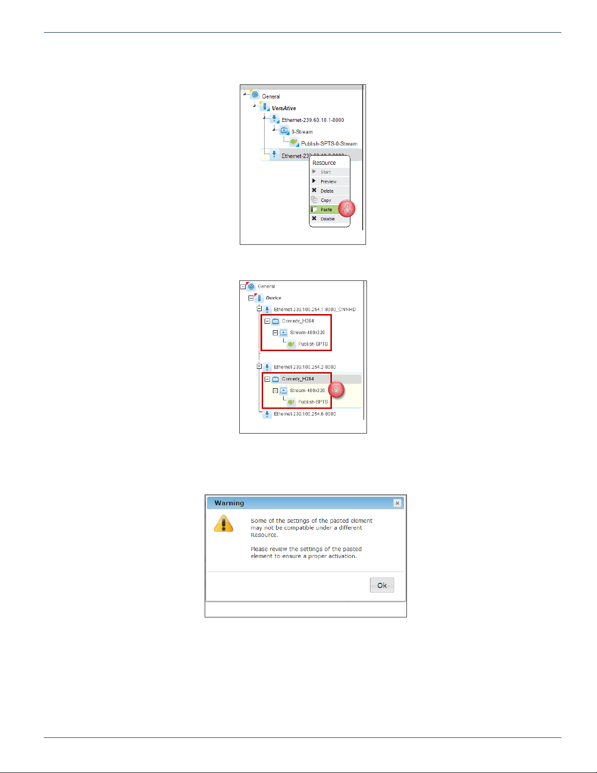
4. Right click the Recipient Resource and select Paste from the menu, Figure 1-8.
4
5
Figure 1-8: Select Paste
5. An exact copy of the stream is replicated on the new Resource, Figure 1-9.
CHAPTER 1: GUI ENVIRONMENT
Figure 1-9: Stream Replicated
WARNING The replicated Streams will have identical properties to the copied Streams so
conicting properties must be edited manually before the Stream may be started. A warning is
given, see Figure 1-10.
Figure 1-10: Stream Replication Warning
VersAtive®Pro Enhanced – Operation Manual 1-7
Page 12

CHAPTER 1: GUI ENVIRONMENT
6
7
8
9
13
14
10
15
11
16
12
17
6. Click to select the new Stream in the Tree View, Figure 1-11.
7. You may Rename the Stream to something meaningful or leave as the default name.
8. Edit Video, Audio & Video Pre-processing Parameters as required.
9. Click Save to save changes to the Stream.
Figure 1-11: Update Copied Stream Parameters
10. Click the Publish in the Tree View to open the parameters window, Figure 1-12.
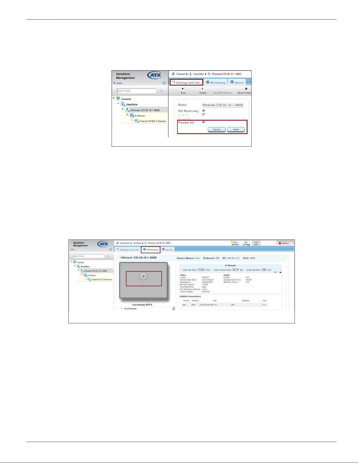
11. You may Rename the Publish to a meaningful name or leave the default name.
12. Tick the box next to any of the PIDs for audio, Teletext and private data which should be active; these are unselected
by default during the Paste operation.
13. Next, Tick the box of the Connection to be edited. There could be more than one connection to be edited.
14. Click Edit to enable changing the IP address and input interface port.
15. Next, Edit the IP address to the correct value for this publish and select the appropriate interface.
16. Click Apply to apply the changes to the Connection.
17. Click Save to save all of the changes to the publishes.
Figure 1-12: Update Copied Publish Parameters
1-8 VersAtive®Pro Enhanced – Operation Manual
Page 13
GENERAL (GLOBAL) CONFIGURATION
1
2
3
2. General (Global) Conguration
General conguration represents the Platform Global settings. This is the top level of the Tree View.
2.1 Chapter Contents
• “General Tool Bar”
• “General Right Click Menu”
• “Products Upgrade”
• “System Time”
• “User Management”
• “Licence”
• “SNMP”
2.2 General Tool Bar
Conguring Global Platform settings:
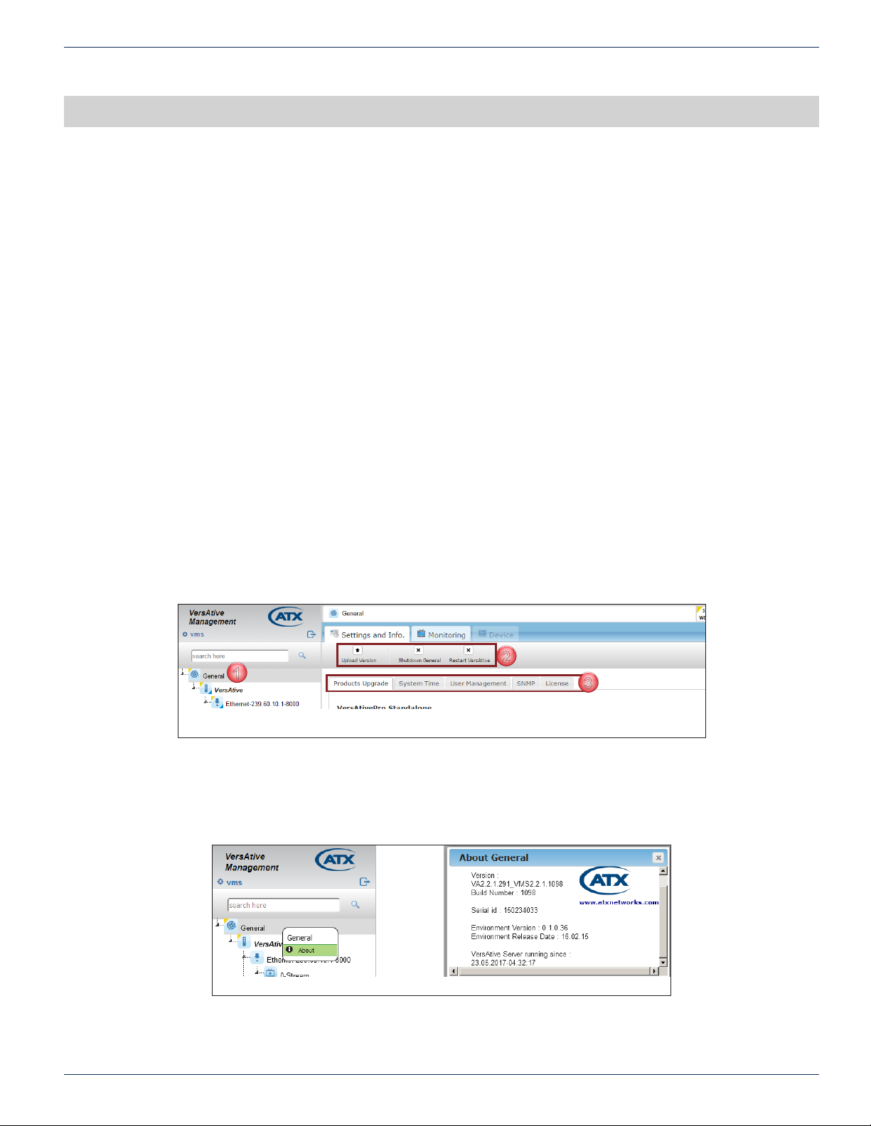
1. Click the General icon at the top level of Tree View to select it, Figure 2-1.
2. Tool Bar options allow shutting down or restarting VersAtive as well as uploading new rmware.
◦ Upload Version - Uploads new rmware version, to upgrade the VersAtive system. See “2.4 Products
Upgrade” on page 2-2 for procedure.
◦ Shutdown General - This gracefully shutdowns the unit. When the unit is shutdown, the front panel
Power button must be pressed locally to power the unit back up again.
◦ Restart VersAtive - Restarts the entire user interface; warm re-boot of the machine.
3. Tabs are presented in the Pane View for more specic system conguration.
CHAPTER 2: GENERAL (GLOBAL) CONFIGURATION
Figure 2-1: General Conguration Tabs
2.3 General Right Click Menu
You may right click the General icon then select About to view more details about the platform, Figure 2-2, such as the
rmware version, hardware serial number, environment version and server uptime.
Figure 2-2: General - Right Click Menu
VersAtive®Pro Enhanced – Operation Manual 2-1
Page 14
CHAPTER 2: GENERAL (GLOBAL) CONFIGURATION
1
2
3
1
2
3
4
2.4 Products Upgrade
Products upgrade (Firmware Upgrade), when available, is obtained from ATX Networks Technical Support group. Obtain the
le and save it to your Management Computer before beginning the upgrade.
2.4.1 View Current Firmware Version
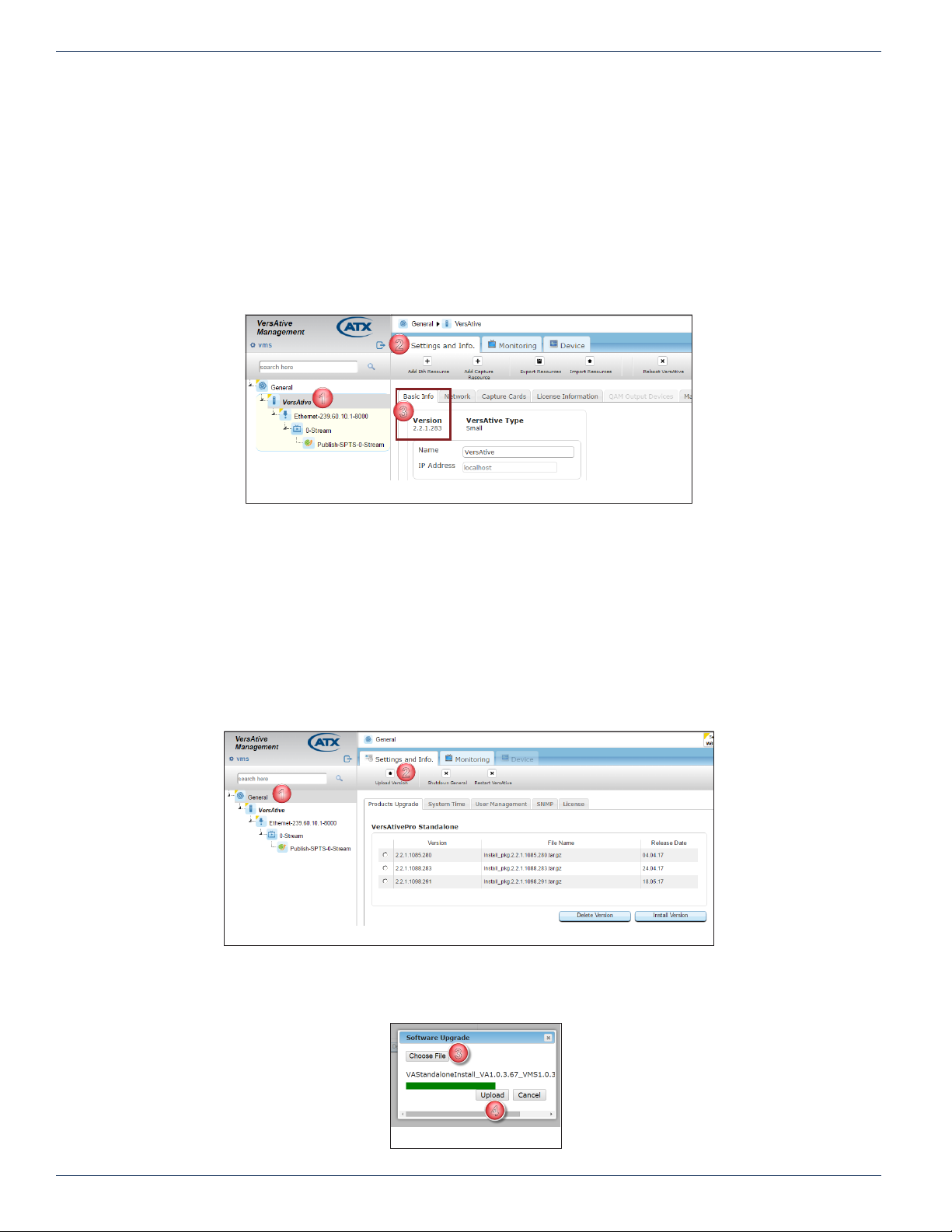
Start by logging into the system to be upgraded then view the current version of rmware, Figure 2-3.
1. Click on the VersAtive Device.
2. Click the Settings and Info upper tab if it is not selected.
3. In the Basic Info lower tab, the version is displayed below the tab.
2.4.2 Upgrade Firmware
Firmware is obtained from ATX Networks Technical Support group. Save the le rst to your local PC or accessible drive.
Procedure
This procedure explains how to upload then install new rmware versions to the VersAtive Pro. After uploading, the rmware
will reside on the integral Device hard drive for subsequent installation now or at a later time. Uploading saves the rmware to
the Device hard drive it does not install the rmware.
1. Click on the General icon in Tree View, Figure 2-4. The page shows saved rmware versions, allows reinstalling
previous versions or deletion of versions no longer needed.
2. Click Upload Version on the Tool Bar to upload another new version.
Figure 2-3: Installed Version
Figure 2-4: Upload Version
3. In the Dialog box that opens, click Choose File then browse to locate the le stored on your computer, Figure 2-5.
4. Click Upload to begin the process.
Figure 2-5: Select File
2-2 VersAtive®Pro Enhanced – Operation Manual
Page 15
CHAPTER 2: GENERAL (GLOBAL) CONFIGURATION
5
6
7
8
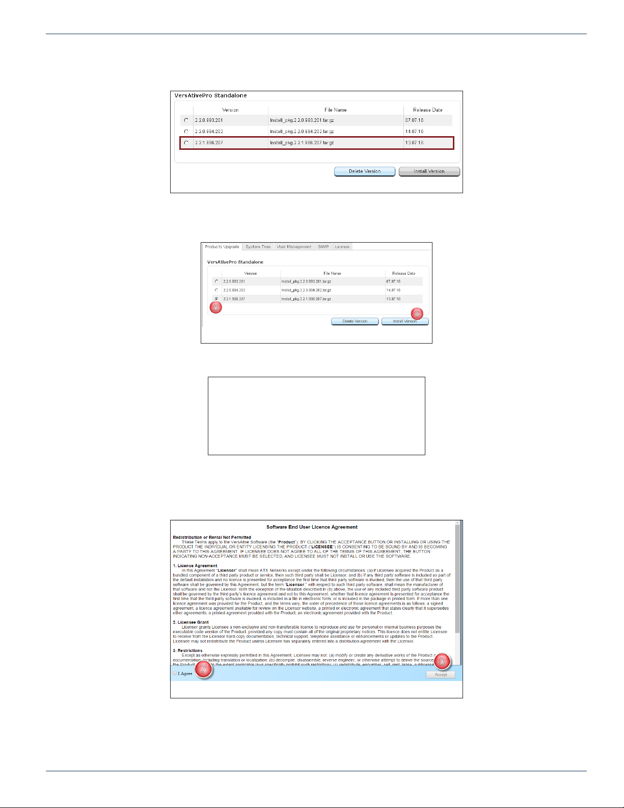
When the upload is complete, the new version will be listed below any previous versions, Figure 2-6.
Figure 2-6: New Uploaded Version
5. Click the selector Button to select the rmware you just uploaded, Figure 2-7.
6. Click Install Version.
Figure 2-7: Install Version
The rmware upgrade process will begin and a progress screen is presented, Figure 2-8.
Figure 2-8: Install Progress
• Soon, the SEULA(Software End User Licence Agreement) is presented, Figure 2-9.
7. Click the I Agree box.
8. Click Accept.
Figure 2-9: Accept SEULA Agreement
Login to the GUI and check the Device Basic Info page to see that the rmware is installed, see “2.4.1 View Current Firmware
Version” on page 2-2 and Figure 2-3.
VersAtive®Pro Enhanced – Operation Manual 2-3
Page 16
CHAPTER 2: GENERAL (GLOBAL) CONFIGURATION
1
2
3
4
5
6
1
2
3
2.5 System Time
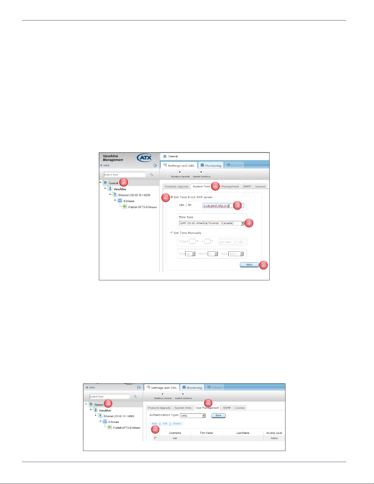
System time is set by default to be set manually but it may also be set to be automatically updated by a dened NTP server if
the VersAtive Device has access to either a local server or internet NTP servers.
2.5.1 Change Time Zone & NTP Server
The Time and Date are set manually by factory default and assumes that Internet access is not available. Use of an NTP
server assumes that the VersAtivePro has access to DNS servers and Internet.
1. Click General Icon at top of Tree View, Figure 2-10.
2. Click the System Time tab.
3. Select the Button ‘Set Time from NTP server’.
4. Enter the IP Address or URL of the desired NTP server.
5. Select the appropriate Time Zone from the dropdown menu.
6. Click the Apply button.
2.6 User Management
A single user with Administrator authority is dened by default but users may be added or managed as required.
2.6.1 VMS Authentication
This is the only authentication type and relies on a username and password for security.
Add User
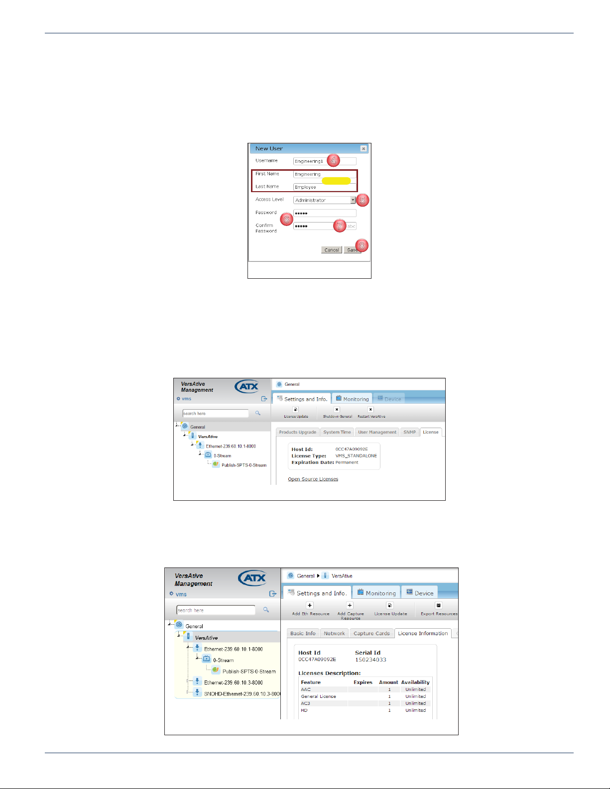
1. Click the General Icon at top of Tree View to select it, Figure 2-11.
2. Click the User Management tab.
3. Click New.
Figure 2-10: NTP Time Server Conguration
Figure 2-11: Add New User
2-4 VersAtive®Pro Enhanced – Operation Manual
Page 17
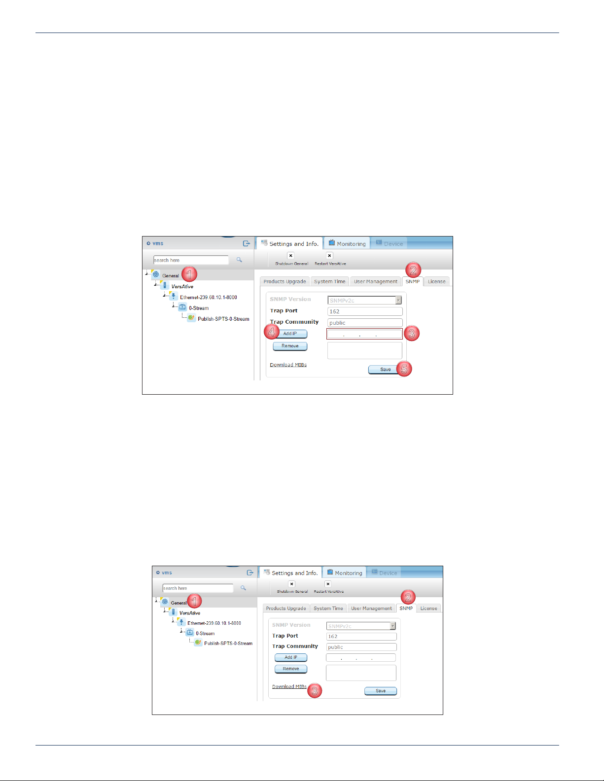
4. Enter Username for new user, Figure 2-12 (a user’s actual rst and last name may also be entered, optional).
4
5
6
7
8
5. Select the Access Level for new user.
6. Enter and conrm Password for new user (password will be masked by default).
7. Mousing over the password entry reveals an ‘abc hotspot’. Click abc to show password momentarily.
8. Click Save.
2.7 Licence
The VersAtivePro relies on installed licenced software and you may view licences if required.
CHAPTER 2: GENERAL (GLOBAL) CONFIGURATION
Optional
Figure 2-12: New User Cong
2.7.1 General Licence
Click the General icon in Tree View to view this page which is for information only and displays the VMS licence installed on
the platform. Open source licences may be viewed by clicking the link.
2.7.2 Device Licence
In the Tree View, click the Device icon to view the transcoding Device Licences installed on the platform. The licence is
permanent. Also the Device Host ID (the MAC Address of management port eth0) and serial number are displayed.
Figure 2-13: General Licence
Figure 2-14: Device Licence Page
VersAtive®Pro Enhanced – Operation Manual 2-5
Page 18
CHAPTER 2: GENERAL (GLOBAL) CONFIGURATION
1
2
3
4
5
1
2
3
2.8 SNMP
The Device may be congured to sent SNMP traps to a remote SNMP manager. At this time the Device supports SNMPv2c.
The Port default is 162 which is the well known port for SNMP and trap community is Public, both of which may be changed.
2.8.1 Add SNMP Remote Manager
Multiple SNMP managers may be added to receive traps.
1. Clickthe General Icon at top of Tree View to select it, Figure 2-15.
2. Click the SNMP tab.
3. Enter the IP Address of the remote SNMP manager.
4. Click Add IP button to add this IP address to the list.
5. Click Save to apply the changes.
• Repeat to add more SNMP Managers.
2.8.2 Download and Compile the MIB
The MIB will need to be compiled to the SNMP Manager and it is stored locally on the Device hard drive. It may be obtained
from the link on the SNMP tab.
Procedure
This procedure explains how to access the Device MIBs and extract them to the SNMP Manager.
1. Click the General Icon at top of Tree View to select it, Figure 2-16.
2. Click the SNMP tab.
3. Click the link Download MIBs.
4. Open the downloaded zip le with any zip le client.
5. Extract the two .txt les and compile the les into the SNMP Manager.
Figure 2-15: Add SNMP Manager
Figure 2-16: Download MIB
2-6 VersAtive®Pro Enhanced – Operation Manual
Page 19

2.8.3 System Traps
The traps listed in Table 2.8a are sent by the system to the remote SNMP Managers.
Table 2.8a: System Traps
vmsVersionSupportTrap "Error: This trap appears when VMS version doesn't support the version of the VersAtive "
CHAPTER 2: GENERAL (GLOBAL) CONFIGURATION
Trap Name Description
VMS General Traps
vmsLicenseUpdateTrap
vmsLicenseExpirationTrap
treeAddTrap
treeDeleteTrap
treeEditTrap This trap can be an error, info or edit. This trap appears when the user edits the VMS tree
treeEnableTrap "This trap appears when the user enables/disables the tree in the VMS. "
mysqlUnusedTablesDeletedTrap "This trap appears when one of the unused tables was deleted from MySQL. "
userAddTrap "This trap appears when a new user is added to VMS successfully. "
userDeleteTrap "This trap appears when a user is deleted from VMS successfully. "
userUpdateTrap
userLoginTrap
This trap can be an error or info. - Error trap appears when the license update fails. - Info
trap appears when the license is updated successfully.
"This trap can be an error or a warning. - Error trap appears when the license is expired.
- Warning trap starts to appear 7 days before the VMS license expires. "
VMS DB Traps
VMS User Management Traps
"This trap appears when the user is updated in the VMS. Update can be in the user name,
password or permissions. "
"This trap appears in two situations: When the user logs in to the VMS successfully or
unsuccessfully. "
userLogoutTrap "This trap appears when the user successfully logs out. "
VersAtive Communication Traps
versativeConnectTrap "This trap appears when the VersAtive connects successfully to the VMS. "
versativeTimeoutTrap "This trap appears when there is no response from the VersAtive. "
versativeTakenToOtherVmsTrap
versativeTakenFromOtherVmsTrap
versativeGeneralExternTrap "This trap appears when a non-handled by VMS event received from VersAtive. "
versativeGeneralErrorTrap
versativeSwUpgradeTrap
versativeSetCongurationTrap
VersAtive®Pro Enhanced – Operation Manual 2-7
"This trap appears when the VersAtive is taken to another VMS. The VersAtive becomes
disabled on the current VMS. "
"This trap appears when the VersAtive is taken from another VMS. The Versative
becomes disabled on the other VMS. "
VersAtive General Traps
"ERROR - This trap appears when the VMS receives a 'General Error' event from the
VersAtive. "
"This trap appears when the Versative software is upgraded. This trap can be an error or
info. The error indicates that the software upgrade failed. "
"This trap appears when the VersAtive conguration is set successfully or unsuccessfully.
This trap is only info. There are two messages: 'Conguration set Successfully' or 'Failed
to Set Conguration' "
Page 20

CHAPTER 2: GENERAL (GLOBAL) CONFIGURATION
Trap Name Description
versativeVersionTrap
versativeDuplicateHostidTrap This trap appears when two VersAtive machines has the same Host ID.
versativeCreateInputIPCannelTrap
versativeFrameRateDropTrap "Frame Rate dropped to more then 10% from conguration. "
versativeResourceStartTrap
versativeResourceStopTrap
versativeDeleteSessionErrorTrap
versativeTsAnalyzeErrorTrap
versativePipelineEventTrap
versativeMonitorSignalStateTrap
versativeMonitorConnectionErrorTrap
versativeMonitorResourceStatusTrap
versativeResourceRedundancyStopTrap
versativeResourceRedundancySwitchTrap
"This trap appears when the VMS performs sync with VersAtive, and VersAtive Version
is Changed. This trap can be error or info. - Info: VersAtive Version OK. - Error: VersAtive
Runs NOT Supported Version. "
VersAtive Streaming Traps
"This trap appears when the Resource Starts playing. This trap can be either an Error
or Info. - Error: says that the Resource failed to start and the reason for the failure. - Info:
says that the resource is started. "
"This trap appears when the resource stops playing. This trap can be either an Error or
Info. - Error: says that the resource failed to stop and the reason for it. - Info: says that the
resource is stopped. "
"This trap appears when the Versative fails to delete a session XML le. This trap can be
only an Error. "
"This trap appears when the VersAtive fails to analyze a transport stream. This trap can
only be an error. "
"This trap appears when the VersAtive has a problem with the pipeline and cannot start
playing. This trap can only be an error. "
"This trap appears when the VersAtive doesn't detect a video signal. This trap can only be
an error. The message says that the VersAtive can not detect a video signal. "
"This trap appears when the VersAtive has no connection to publish point or VersAtive
cannot publish the stream. This trap can be only an Error. "
"This trap appears when there is no input for the resource and the VersAtive retries to
connect. This trap can be a warning or info. - Warning: indicates the name of the resource
and that the VersAtive is retrying. - Info: indicates the name of the resource and that the
streaming is OK. "
"This trap appears when no redundancy for the resource is found. This trap can only be
an error. The message indicates that the resource is stopped and that no backup for the
resource is found. "
"This trap appears when the resource redundancy switched to backup. This trap can only
be a warning. The message says that the Resource switched to the backup resource. "
versaFtiveNoSignalTrap "This trap appears there is no signal at the input side - Only for encoding. "
versativeInternalDataFlowErrorTrap
versativeFailToOpenAudioDeviceTrap "This trap appears when audio device cannot be open - Only for encoding. "
versativeDataTimeoutTrap "This trap appears when the Resource receive Input Data timeout. "
versativeStreamEndedTrap "This trap appears when Stream is close due to an internal server error. "
versativeFailedToConnectToDrmSrvrTrap "This trap appears when the VersAtive fails to connect to the DRM server. "
versativeProgressReportTrap "This trap is holding progress of ofine transcoding. "
versativeVideoBitrateTrap "This trap appears when the video bit rate changes in the monitor of the resource. "
versativeFramerateTrap "This trap appears when the video frame rate changes in the monitor of the resource. "
versativeFrameDropTrap "This trap appears when the video frame rate drops in the monitor of the resource. "
2-8 VersAtive®Pro Enhanced – Operation Manual
"This trap appears when the VersAtive has a problem with internal data ow. This trap
can only be an Error. "
Page 21

CHAPTER 2: GENERAL (GLOBAL) CONFIGURATION
Trap Name Description
versativeAudioBitrateTrap "This trap appears when the audio bit rate changes in the monitor of the resource. "
versativeConnectToPublishServerTrap No Description available.
versativeSrcInputTimedOutTrap "This trap appears when the source has a data timeout "
versativeMissingPtsDataTrap "This trap appears when there is no PTS in PES header. "
versativeRolloverTrap "This trap appears when PTS of elementary streams overlaps. "
versativePtsDiscontinuityTrap
versativeCantRecordAudioFastEnoughTrap "This trap appears when the VersAtive can't record audio fast enough. "
versativeFailToStartRtmpServerTrap "This trap appears when the VersAtive fails to connect to the RTMP server. "
versativeOvfFifoSizeTrap "This event appears when the SPTS MUX gets overowed. "
versativeAc3AudioChangedTrap "This trap appears when the AC3 audio changes. "
versativeDelayCalculationTrap "This trap appears when the multiplexer loses sync. "
versativeAliveAfterEosTrap "This trap appears when le transcoding is almost complete - Ofine. "
versativeNoInputDataTrap "This trap appears when no input data for the resource is detected. "
versativeExternalStopSignalReceivedTrap "This trap appears when User initiates 'stop resource'. "
versativeEvntPsiMonitoringTrap "This trap appears when there is a PSI change at the input. "
versativeEvntCcErrorTrap "This trap appears when the resource has a continuity count error. "
versativeCapcardInputChangedTrap "This trap appears when the capture card format changes. "
versativeMcEncValidationErrorTrap
"This trap appears when the program time stamp is changed. this can happen when the
transport stream changes. "
This trap appears when there is an MPEG2 conguration error. This trap can only be an
Error.
versativeClosingConnectionsTrap "This trap appears when the VersAtive closes all the streams. "
versativeFailedToPutFileTrap This trap appears when an HLS or RTMP stream fails to publish.
versativeSignalDetectedTrap "This trap appears when a signal for resource is detected. "
versativeReconnectTrap "This trap appears when the VersAtive reconnects successfully to RTMP server. "
versativePipeEvntNoUdpInput "This trap appears when there is no UPD input for the pipeline. "
VersAtive Hardware Traps
versativeMonitorCpuHeatTrap
versativeMonitorCpuLoadTrap
VersAtive®Pro Enhanced – Operation Manual 2-9
"This trap appears when the CPU heat nears it's maximum operation temperature. This
trap can be an error or info. - Info message indicates that the CPU heat is at 70C degrees.
- Error message indicates that the CPU heat is at 75C degrees. "
"This trap appear when the CPU usage nears it's maximum capacity. This trap can be
an error or info. - Info message indicates that the CPU usage is at 75 percent. - Error
message indicates that the CPU usage is at 85 percent. "
Page 22

CHAPTER 2: GENERAL (GLOBAL) CONFIGURATION
Trap Name Description
versativeMonitorMemoryUsageTrap
versativeMonitorEthLimitTrap
versativeMonitorDemodStatusTrap
versativeMonitorDiskUsageTrap This Trap indicates that the Internal Hard Disk Space is Low.
"This trap appears when the memory usage nears it's maximum capacity. This trap can
be an error or info. - Info message indicates that the memory usage is at 85 percent. Error message indicates that the memory usage is at 92 percent. "
"This trap appears when the Ethernet card nears it's maximum capacity. This trap can
be an error or info. - Info message indicates that the Ethernet card is at 80 percent of it's
capacity. - Error message indicates that the Ethernet card is at 90 percent of it's capacity. "
This trap shows the status of the demod card (enabled/disabled or locked/not locked).
This trap can be an error or info. - Error message indicates that the demod card is not
locked. - Info message indicates that the demod card is locked, enabled or disabled.
versativeMonitorAnalogCardHeatTrap This Trap indicates that the Analog Card Temp. is High.
VersAtive MPTS MUX and MQAM Traps
versativeMuxStartTrap
versativeMuxStopTrap
versativeMuxMonitorTrap
versativeMuxStillNoTsTrap "Not Used. "
"This trap appears when the mux is started. This trap can be an error or info. - Error
message indicates that the mux didn't start. - Info message indicates that the mux started
successfully. "
"This trap appears when the mux is stopped. This trap can be an error or info. Error
message indicates that the mux didn't stop. Info message indicates that the mux stopped
successfully. "
"This trap appears when the mux monitor sends a trap. This trap can be an error or
info. - Error message indicates that multiplexer monitor received time-out. - Info message
indicates that the mux monitoring is OK. "
versativeMuxEventLostTsTrap "This trap appears when the input transport stream for the mux is lost. "
versativeMuxEventBitrateMismatchTrap
versativeMqamSyncErrorTrap "This trap appears when MQAM receives an error. This trap can only be Error. "
versativeMuxReStartTrap
"This trap appears when the output bit rate is less than the sum of input bit rates. This
trap can only be an Error. "
This trap appears when the mux is restarted. This trap can be an error or info.
- Error message indicates that the mux didn’t restart.
- Info message indicates that the mux restarted successfully.
2-10 VersAtive®Pro Enhanced – Operation Manual
Page 23
DEVICE CONFIGURATION
1
3
4
3. Device Conguration
Device Conguration involves setting up the input and output interfaces of the hardware platform. To view this page, click the
Device icon in the Tree View. In this manual the Device is named VersAtive but you may change this name to suit.
3.1 Chapter Contents
• “Settings and Info”
• “Network”
• “Licence Information”
• “Maintenance”
3.2 Settings and Info
Most of the Device conguration is done from the Settings and Info page.
3.2.1 Basic Info Page
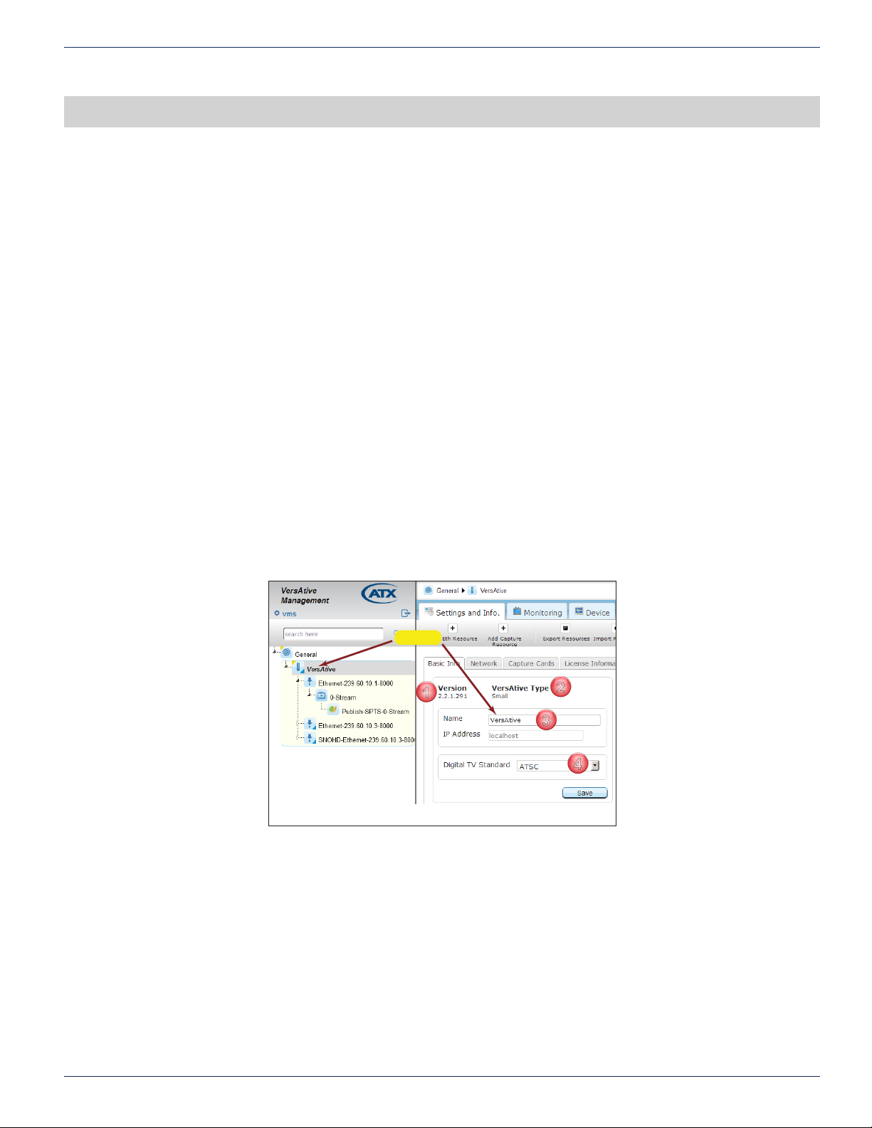
The Basic Info tab shows information about the hardware model and platform, in this case VersAtivePro Small, as well as the
installed version of rmware, Figure 3-1. The main information and congurable features are:
1. The version of installed rmware.
2. The hardware model of the platform.
3. The editable Name of the Device. If the name is changed, click Save to apply that change.
4. Drop down menu to change TV Standards, currently set at ATSC in this example but may be changed to DVB. If the
TV Standard is changed, click Save to apply that change.
CHAPTER 3: DEVICE CONFIGURATION
Device
Figure 3-1: Basic Info Page
2
VersAtive®Pro Enhanced – Operation Manual 3-1
Page 24
CHAPTER 3: DEVICE CONFIGURATION
1
2
3
4
5
7
6
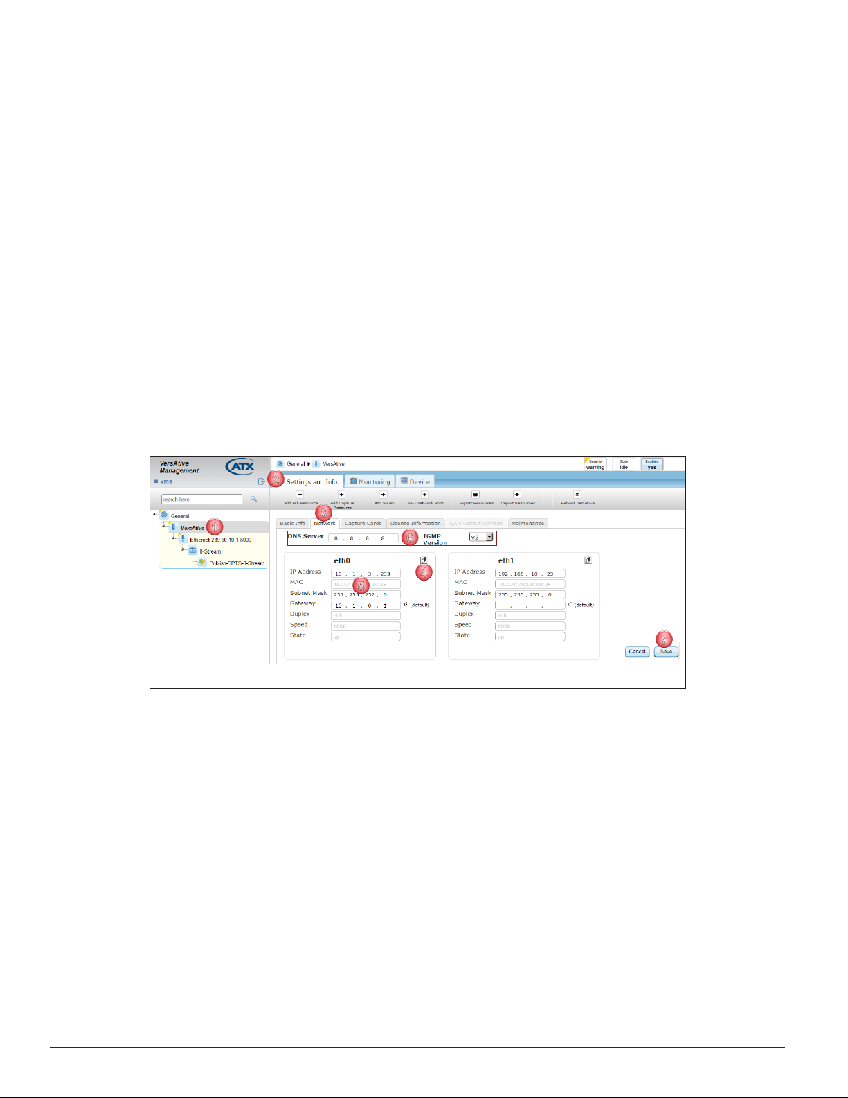
3.3 Network
The Management Port IP address and Streaming Port addresses are dened on the Device Network tab. There may be more
or less Ethernet ports depending on the model and there may even be Virtual ports if a VLAN has previously been dened.
NOTE Changes to the Management Port address will result in a platform reboot. You will need to
login on the new IP address.
3.3.1 Procedure to Change IP Address
This procedure explains how to change Ethernet port IP addresses.
1. Click on the Device icon to select it in Tree View, Figure 3-2.
2. Click the Settings and Info tab if it isn’t already selected.
3. Click the Network tab.
4. Optionally, click the Erase Icon for the eth port to be changed to delete all current settings. Alternately, you can just
edit the current settings.
5. After editing settings as required for any eth interface, click the Gateway adjacent radio button to make the selected
gateway the default. Other gateways may also be dened for each interface.
6. Optionally, select the IGMP version from the dropdown menu, (version 2 and 3 are available) and change the DNS
server IP address to a desired server.
7. Click Save to apply all of the changes.
Figure 3-2: Congure Network Settings
3-2 VersAtive®Pro Enhanced – Operation Manual
Page 25
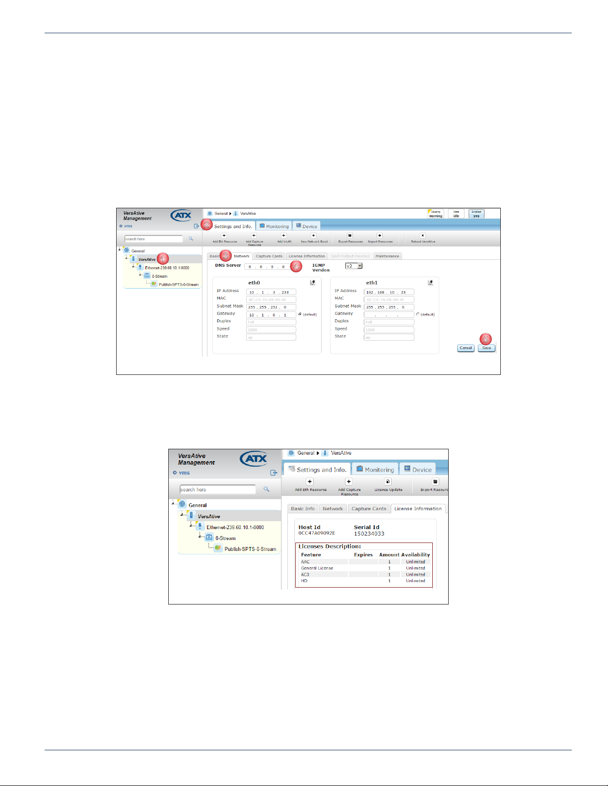
3.3.2 Congure a DNS Server
1
2
3
4
5
A DNS server will be required if a URL is entered anywhere on the platform instead on an IP address.
Procedure
This procedure explains how to change the DNS Server IP address.
1. Click on the Device icon to select it, Figure 3-3.
2. Select Settings and Info tab if it isn’t already selected.
3. Select the Network tab.
4. Enter the IP Address of the DNS server.
5. Click Save.
CHAPTER 3: DEVICE CONFIGURATION
3.4 Licence Information
Select the Device in Tree View then the Licence Information tab to view installed VersAtive Device Transcoding licences.
Licences do not expire and are unlimited in transcoding capabilities.
Figure 3-3: Congure DNS Server
Figure 3-4: Platform Transcoding Licences
VersAtive®Pro Enhanced – Operation Manual 3-3
Page 26
CHAPTER 3: DEVICE CONFIGURATION
1
2
3
1
2
3
1
2
3
2
3
4
5
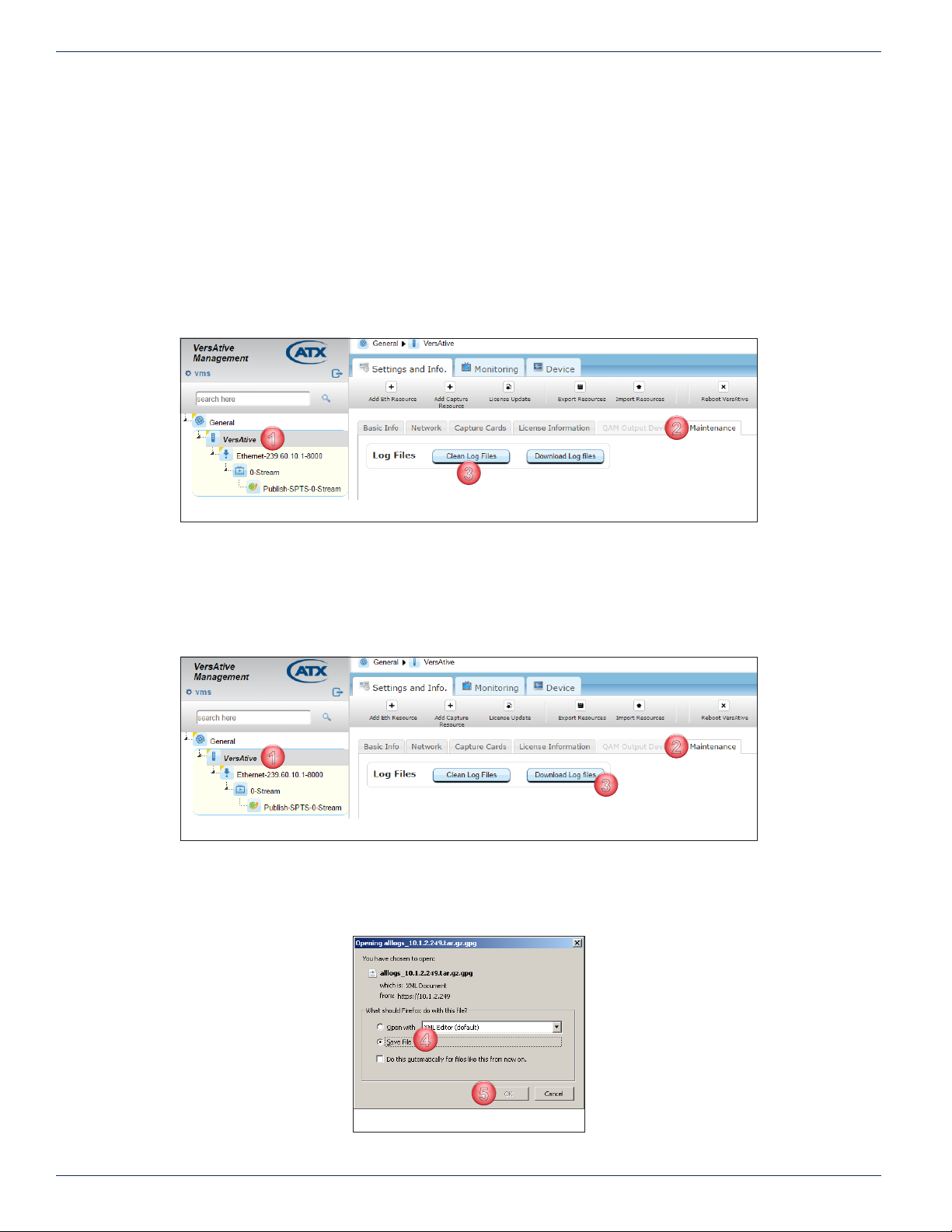
3.5 Maintenance
The system log le may be downloaded for troubleshooting purposes by ATX Networks Technical Support only. This le is not
human readable; it is not in a text format. If problems have been encountered and you have contacted ATX Networks Technical
support, you may be asked to clean the log les before collecting a set of current logs. This deletes existing log les as the
Device is always logging all activities which can result in too long or cumbersome a log le to be useful.
Clean Log Procedure
1. In the Tree View click the Device icon to select it, Figure 3-5.
2. Click the Maintenance tab.
3. Click the Clean Log Files button.
There is a prompt to delete all the log les; choose Yes. You may get an error message (bug) but the log les were deleted.
Figure 3-5: Clean Log Files
Download Log Procedure
1. In the Tree View click the Device icon to select it, Figure 3-6.
2. Click the Maintenance tab.
3. Click the Download Log Files button.
1
Figure 3-6: Download Log File
4. There is a prompt to save or open the le; choose Save File, Figure 3-7.
5. Click OK (your browser may present this slightly differently).
The le is saved in your Browser Downloads folder. Send this le to your support rep.
Figure 3-7: Save Log File
3-4 VersAtive®Pro Enhanced – Operation Manual
Page 27
TRANSCODING APPLICATION
1
2
3
4. Transcoding Application
This chapter describes how to set up an IP stream from an Ethernet port for Transcoding and publishing an SPTS stream.
4.1 Chapter Contents
• “Ethernet Resources”
• “SPTS Stream Conguration”
• “Create an SPTS Stream”
• “Publish Conguration”
• “Publish an SPTS Stream”
• “Start the Stream”
4.2 Ethernet Resources
An Ethernet Resource is an input to the platform which exists on one of the Ethernet interfaces as an IP stream. These
resources are used as source content for subsequent transcoding.
CHAPTER 4: TRANSCODING APPLICATION
4.2.1 View Resource Attributes
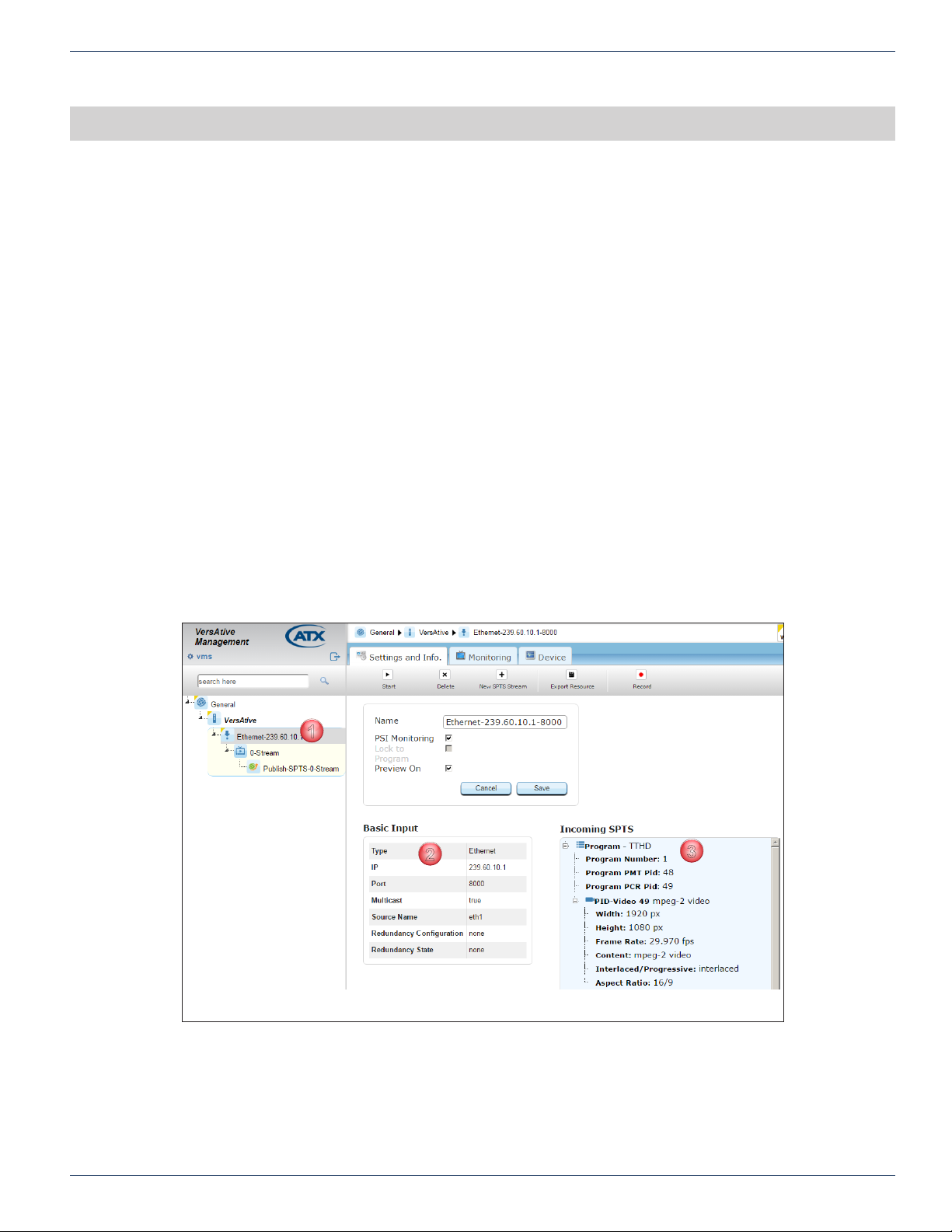
Existing Ethernet resource attributes may be viewed by clicking the resource in the Tree View.
1. Click on the Resource icon in Tree View to select it, Figure 4-1.
2. View Basic Input parameters such as IP Address and Port, and the eth port it appears on.
3. View SPTS stream PIDs and the stream parameters.
Figure 4-1: View Ethernet Resource Attributes
VersAtive®Pro Enhanced – Operation Manual 4-1
Page 28
CHAPTER 4: TRANSCODING APPLICATION
1
2
3
4
5
6
7
8
4.2.2 Create an Ethernet Resource
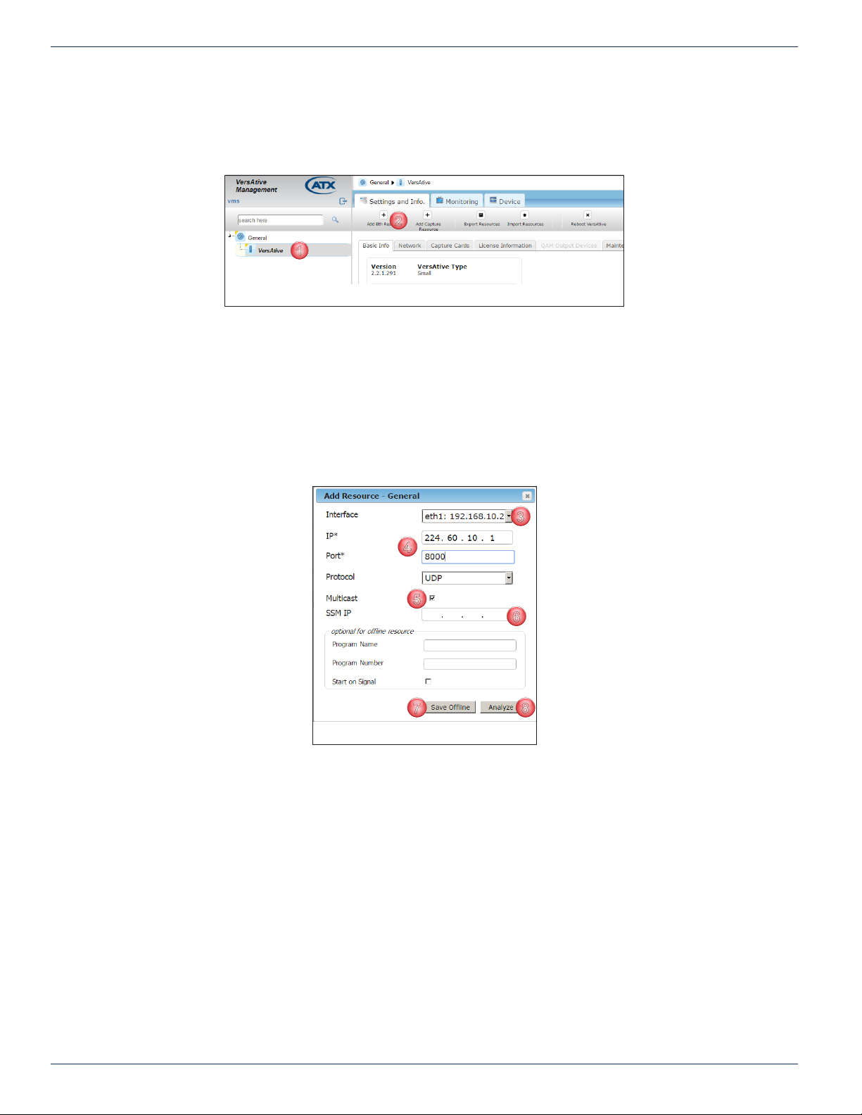
1. Click on the Device icon to select it, Figure 4-2.
2. Click Add Eth Resource on the tool bar (or Right Click menu).
3. Choose the Ethernet port that the stream appears on from the Interface choices, eth0, thru eth5. (Depending on the
model ordered, may be more or less ports), Figure 4-3. There may also be virtual sources (VLAN) if any were created.
4. Enter the IP address, Port and choose the Protocol of the IP stream to be ingested.
5. Tick the Multicast box if this is a multicast stream with an address in the multicast range.
6. If the Stream is a Source Specic Multicast (SSM), enter the SSM IP Address.
7. If the stream is actually not present but you know it will be later, enter the Program Name, Program Number, select
Start On Signal then click Save Ofine to save the settings (The stream will start when the signal is detected).
8. Click Analyze (only for streams that exist currently on a physical or virtual input; not required for Save Ofine).
Figure 4-2: Add New Ethernet Resource
Figure 4-3: Fill Resource Form
NOTE: The Save Ofine feature makes is possible to set up streams that are not yet present on
the input ports but you know they will be eventually. This allows the user to make resources for an
upcoming system that hasn’t been established yet. Without the ofine resource feature you can’t
add any Ethernet resource if the VersAtivePro can’t nd any program or service on a given IP.
NOTE: The Start on Signal check box is used when the resources are not currently available. If
and when the external IPTV network is built, the preprogrammed resources will start as soon the
signal is found.
4-2 VersAtive®Pro Enhanced – Operation Manual
Page 29
CHAPTER 4: TRANSCODING APPLICATION
9
10
11
12
13
14
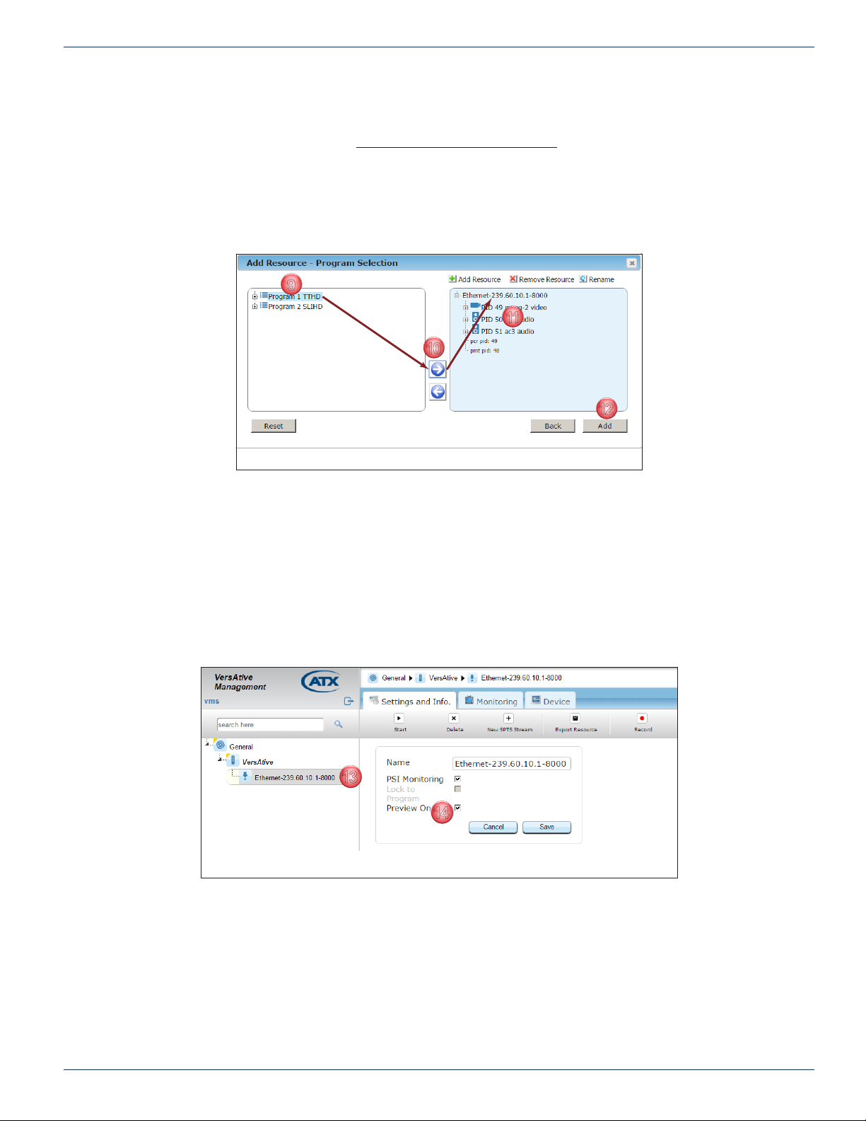
• The programs that are read from the PMT table on that stream will be displayed in the Program Selection window,
Figure 4-4.
9. Click to select a single Program. PID level selection is not supported. Unwanted audio PIDs may be disabled later
at the Publishing stage.
10. Use the Arrow controls to move programs both ways (or Drag and Drop a single program onto the Resource until a
green check mark appears).
11. The program PIDs are added to the Resource. PIDs may be removed by clicking RESET.
12. When nished with the selection, click Add to add this program and create the Resource.
Figure 4-4: Arrow Controls Move Program to Resource
13. The Program is added to the Resource, Figure 4-5, and shown in the Tree View under the Device with the included
SPTS Incoming stream PIDs detailed in the adjacent Pane View. This is automatically saved.
14. The ‘Preview ON’ tick box is selected by default. Untick the box to disable Preview for this resource only and click
Save if a change was made.
NOTE: The Preview function requires a small amount of Device CPU cycles. If the Device is
running close to 100% CPU utilization as witnessed by the Device Monitoring page, see “6.2
Monitoring the Device” on page 6-1, disabling preview can help with that condition. Each
Resource Preview function must be disabled individually so click each active resource in the Tree
View to access this control.
Figure 4-5: Resource Added to Tree View
VersAtive®Pro Enhanced – Operation Manual 4-3
Page 30
CHAPTER 4: TRANSCODING APPLICATION
4.3 SPTS Stream Conguration
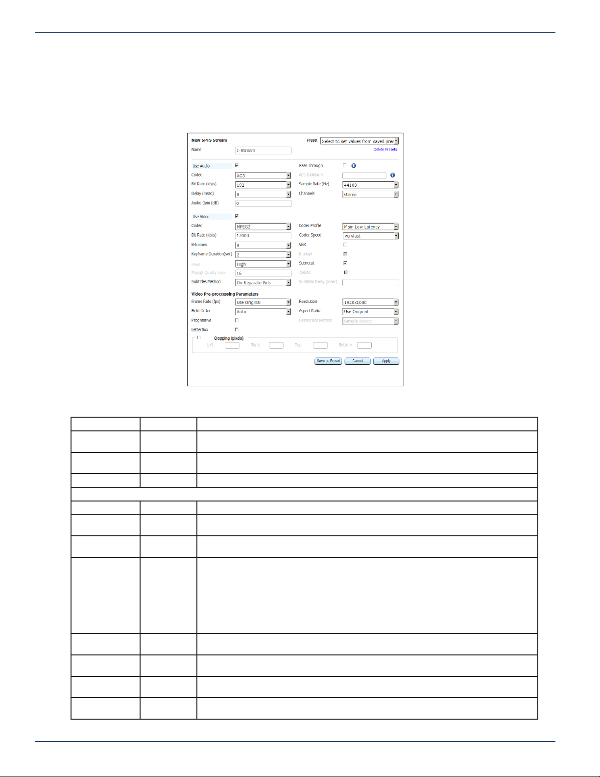
Any number of SPTS Streams may be added to any existing Ethernet Resource. The Ethernet Resource must be created rst,
see “4.4 Create an SPTS Stream” on page 4-6.
For guidance and reference, see the SPTS settings page, Figure 4-6, and SPTS Stream Conguration,Table 4.3a.
Figure 4-6: SPTS Stream Settings
Table 4.3a: SPTS Stream Conguration (See Figure 4-6)
Setting Value Description
Name String The alpha numeric identier that you can assign. This should be a meaningful name which clearly
Preset Dropdown
menu
Delete Presets Link/Button Click link to delete all user saved presets. Does not delete factory dened presets.
Use Audio Tick Box Tick to enable the Audio stream in the output. Default is ticked.
Pass Through Tick Box Tick to enable a pass through of the incoming audio without any changes. Selecting this greys out
Codec Dropdown
menu
AC3 Dialnorm Scroll Control Enabled on AC3 and EAC3 signals only. Controls playback gain within the Dolby® AC3
Bit Rate Dropdown
menu
Sample Rate Dropdown
menu
Delay Dropdown
menu
Channels Dropdown
menu
identies the stream or it’s purpose.
It is possible to dene and save commonly used settings. There are preset proles provided with
pre-dened settings which may be used as a starting point and custom presets saved later.
Audio Encoding Parameters
all audio settings. Default unticked.
Choices, MPEG1/L2, MP3, AAC, AC3, EAC3, HEAAC.
compression system, setting the overall program playback level for loudness normalization.
The audio level between different TV programs, channels, and in particular commercials is
inconsistent. Dialog Normalization was implemented to automatically provide consistent audio
levels and the metadata to accomplish this is included in any Dolby Digital bitstream. Dialog
Normalization does not affect the original audio signals that are fed into the encoder such as
the level or the dynamics of the program. The receiver/decoder reads the dialnorm value in the
metadata and adjusts the level of audio programs so that the dialog is at a consistent and uniform
level. Valid settings: 0 to -31
Audio bitrate. Choices available depend on Codec choice.
Audio sample rate, choices available depend on codec selected; default 48000Hz.
Species the delay of the audio channel compared to Video between -1000 and +1000 msec in
10 msec steps; default is 0.
Number of audio channels. Choices: 5.1 channels, stereo and mono.
4-4 VersAtive®Pro Enhanced – Operation Manual
Page 31

CHAPTER 4: TRANSCODING APPLICATION
Setting Value Description
Audio Gain Scroll control Controls audio gain on all audio codecs. Settings between +12 and -12; Default 0.
Video Encoding Parameters
Use Video Tick box Tick to enable the Video stream in the output.
Codec Dropdown
Codec Prole Dropdown
Bit Rate Integer Enter encoding rate in kbps.
Codec Speed Dropdown
Bframes Dropdown
VBR Tick box Tick to enable variable Bit Rate output then dened bitrate is target bitrate; default is Constant
Keyframe
Duration
B-adapt Tick Box Enabled on H.264 proles only Turn on the adaptive B-frame placement decision algorithm. This
MPEG2 Level Dropdown
Scenecut Tick Box Selected (enabled) by default (and cannot be disabled in MPEG2 Codec), adaptive I-frame
MPEG2 Quality
Level
CABAC Tick box Enabled on H.264 proles. Enables CABAC (Context Adaptive Binary Arithmetic Coder) stream
Subtitles Method Dropdown
Frame Rate(fps) Dropdown
Resolution Dropdown
Field Order Dropdown
Aspect ratio Dropdown
Progressive Tick Box Allows de-interlacing of video frames to convert from Interlace to Progressive if box is ticked;
Deinterlace
Method
Letterbox Tick Box Tick to enable Letterbox mode on SD output resolutions only to t HD content without vertical
Cropping Integer If box ticked, enter number of Pixels to be cropped from each side of the picture.
menu
menu
menu
menu
Dropdown
menu
menu
Scroll Control Only in effect for MPEG2 codec. Controls quality of MPEG2 encoding within the set bitrate.
menu
menu
menu
menu
menu
Dropdown
menu
MPEG2 & H.264 available. Some of the following settings depend on this choice.
Choices of Baseline, Main, High, also Low Latency settings.
Enabled on H.264 proles only. Adjust for best performance based on scene action. Recommended
to use default setting for most streams.
Enabled on H.264 proles. Species the maximum number of concurrent B Frames that H.264
can use; default is 2.
Bit Rate (Un-ticked).
Enabled on H.264 proles only The time period in seconds between IDR keyframes; default is 2
seconds.
setting controls how H.264 decides between placing a P or B-frame. Choice is true (Ticked) or
false (not ticked), default is Box Ticked.
Only in effect for MPEG2 codec. Choice is Main & High.
decisions are enabled. Disabling Scenecut prevents H.264 from generating a key frame when
there is a scene cut in the video; important to keep key frames consistent for multi-bitrate videos.
See Figure 5-4 & Figure 5-3 and description below.
Settings between relative values 0 and 31 with 16 as default. Increase or decrease relative quality.
compression and reverts to CAVLC (Context Adaptive Variable Length Coder) system if un-ticked,
which signicantly reduces efciency and the decoding requirements. Default CABAC (Ticked).
Determines how subtitles (closed captions) are handled; default is On Separate PIDs.
• On Separate PIDs: Subtitles are placed on PIDs separate from video and audio streams.
• Overlay in video: Subtitles are added into the video stream.
• Ignore Subtitles: Subtitles are not passed through.
Video Pre-processing Parameters
Encoded frames per second; default is ‘Use Original’. Choices between 1 and 60.
Select from many choices for the appropriate resolution.
Ordering of elds either Top or Bottom eld rst. Default is Auto.
Choice between 1:1, 4:3 and 6:9 or Use Original; default is Use Original.
default is not ticked (no de-interlace).
Only effective if De-Interlace is selected. De-interlace choices between Simple detect, Simple
detect with Double Frame rate and Linear; default is Linear.
stretching. Activating this switch causes the HD content to t horizontally while presenting black
bars top and bottom. Without this switch, HD content would t horizontally and stretch vertically
to t the output resolution. Not for use on HD output resolutions.
VersAtive®Pro Enhanced – Operation Manual 4-5
Page 32
CHAPTER 4: TRANSCODING APPLICATION
1
2
3
4
5
4.4 Create an SPTS Stream
Multiple SPTS Streams with different parameters may be created for the Ethernet Resource by repeating these steps.
Procedure
This procedure explains how to add SPTS Streams to an existing Ethernet Resource.
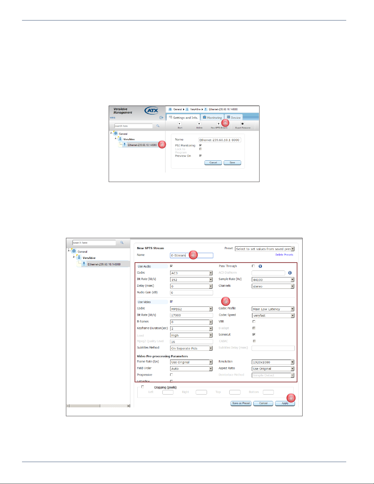
1. Click to select the Ethernet Resource icon in the Tree View, Figure 4-7.
2. Select New SPTS Stream on the Tool Bar.
Figure 4-7: Add New SPTS Stream
3. On the settings page, Figure 4-8, give the stream a meaningful Name such as the service name or accept the default.
4. Edit Video, Audio & Video Pre-processing Parameters as required.
NOTE: For details and guidance on conguring these settings, see “4.3 SPTS Stream
Conguration” on page 4-4.
Figure 4-8: Rene SPTS Stream Settings
5. Click Apply to save and add the SPTS stream to the Tree View, see Figure 4-10 (1).
4-6 VersAtive®Pro Enhanced – Operation Manual
Page 33

4.5 Publish Conguration
This page is used to establish parameters for publishing an SPTS stream, Figure 4-9 and Table 4.5a. Any number of Publishes
may be created for any existing SPTS Stream, however, the SPTS stream must be created rst, see “4.6 Publish an SPTS
Stream” on page 4-8.
CHAPTER 4: TRANSCODING APPLICATION
Figure 4-9: SPTS Publish Settings
Table 4.5a: Publish Settings (See Figure 4-9)
Setting Value Description
Name String The alpha numeric identier that you can assign. This should be a meaningful name which clearly
Format DropDown
Closed
Captioning
Tables
Passthrough
CBR Out Integer Un-tick ‘Automatic’ to enable entering a CBR bitrate for the Video stream.
Automatic Tick Box Tick to turn on Variable Bit Rate output. Un-tick to set to CBR then enter an integer in CBR Out. Default
Program No. xxxx Integer Enter the MPEG program number to change default value.
PCR PID xx Integer Default is PCR PID follows Video PID.
PMT PID xx Integer Program Map table PID.
Video PID xx Integer Video stream PID
Audio Track Tick Box /
ATSC Enable Tick Box Tick to enable ATSC table features.
Service Name String The name or Callsign you assign to this service.
Modulation Mode Dropdown
Virtual Major
Channel
Virtual Minor
Channel
Interface Dropdown
Menu
Tick Box Tick to include the closed caption (Subtitles) if existing.
Tick Box During encode/transcode of video the EIT tables are rebuilt. The PIDs, program number etc. are
Integer
Menu
Integer The ATSC Major Channel number.
Integer The ATSC Minor channel number.
menu
identies the Publish or it’s purpose.
Select format from drop down menu choices of SPTS, Flash and HLS.
possibly changed during the re-packaging process. When the ‘Tables Passthrough’ is checked the EIT
data from the input is passed to the output without change. This feature is present for the case where
there is some unusual data in these tables that is required to pass to the transcoder/encoder’s output.
is ticked, VBR.
Audio PIDs are listed as audio tracks along with their PID number and language. Tick the box to include
and publish this PID. If transcoding, all input PIDs are presented. If encoding, mapped audio PIDs are
presented with their dened language descriptor. Unticked PIDs are not published. Mouse over the Info
Icon to see the language of the audio stream.
ATSC
256 and 64 QAM supported.
Add New Connection
Select the output physical Ethernet port the stream will appear on; choices are eth1, eth2, eth3 or eth4
(Ports available may differ between models and could include VLANs if previously congured).
VersAtive®Pro Enhanced – Operation Manual 4-7
Page 34
CHAPTER 4: TRANSCODING APPLICATION
1
2
3
4
5
6
Setting Value Description
Protocol Dropdown
menu
URL IP Address Enter the IP address or URL for the publish. Entry of URL requires a DNS entry dened on the
Port Integer Enter the port number associated with the URL.
Multicast Tick Box Tick this box if the IP address is within the multicast address range.
Choice between UDP & RTP; default is UDP.
management port IP settings.
4.6 Publish an SPTS Stream
A Publish denes the Output IP Address of the SPTS Stream. Any Stream may have any number of Publishes added by
repeating these steps for each.
Procedure
This procedure explains how to add and SPTS Stream Publish to an existing SPTS Stream.
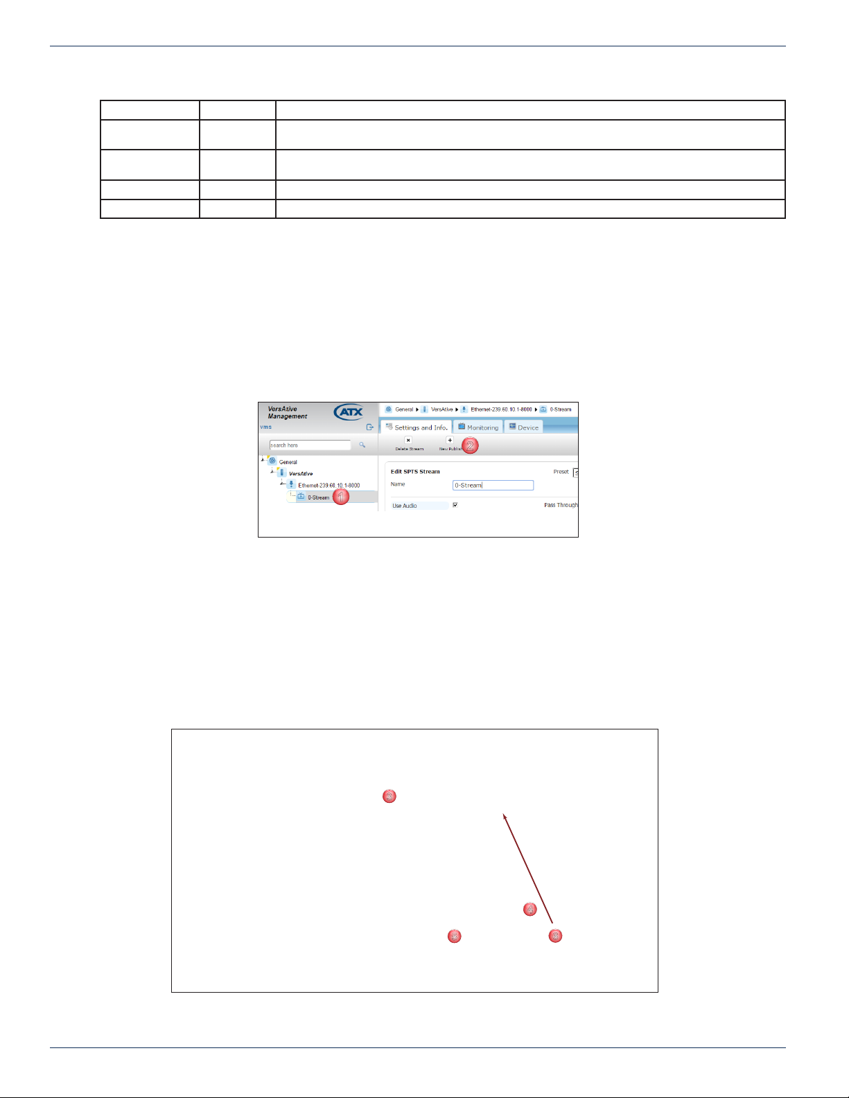
1. Select the SPTS Stream by clicking it, Figure 4-10.
2. Select New Publish on the Tool Bar.
Figure 4-10: New SPTS Publish
3. Give the Publish point a meaningful Name such as IP Address or type of publish or accept the default, Figure 4-11.
4. Add a New Connection by adding IP address and port number then choose the physical Output Ethernet Interface
and protocol (Ports available may differ between models and could include VLANs if previously congured).
NOTE: For details and guidance on conguring these settings, see “4.5 Publish Conguration”
on page 4-7
5. Tick the Multicast box if this is a multicast IP address (default is unticked - unicast).
6. Click Add to create and add the connection to the Connections list, see Figure 4-12. More output connections may
be added, just add more New Connections.
Figure 4-11: Rene Publish Properties
4-8 VersAtive®Pro Enhanced – Operation Manual
Page 35
CHAPTER 4: TRANSCODING APPLICATION
7
9
10
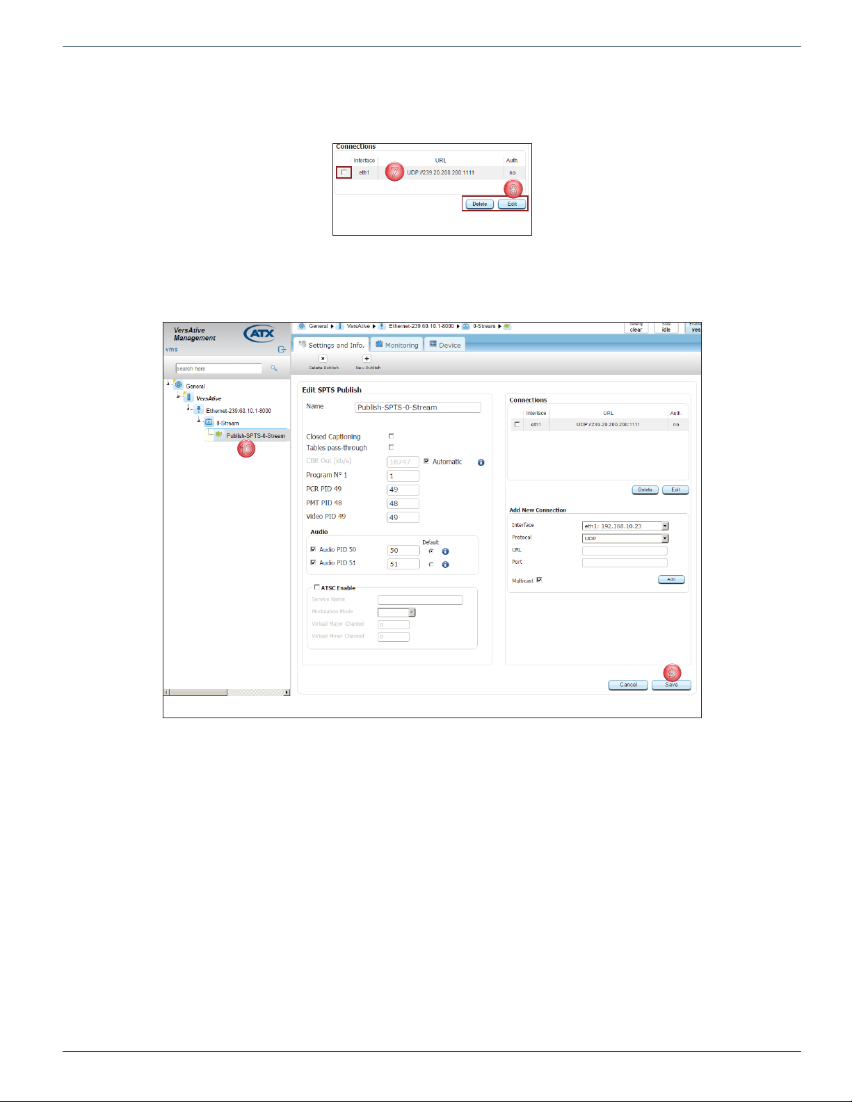
7. Connection is created, Figure 4-12.
8. Connection may be edited (or deleted) by selecting the adjacent tick box then click Edit (or Delete).
8
Figure 4-12: Connection Created
9. After the Connection is created click Apply, or after editing, click Save to apply the changes (the button changes from
Apply to Save once the publish is created), Figure 4-13.
10. The Publish is added to the SPTS Stream and displayed in Tree View.
Figure 4-13: Publish Added to SPTS Stream
VersAtive®Pro Enhanced – Operation Manual 4-9
Page 36
CHAPTER 4: TRANSCODING APPLICATION
1
2
3
4.7 Start the Stream
The streaming process is started from the Resource icon (Right Click Menu) or the Resource icon Tool Bar. Resources may
be started individually from the Resource icons or all at once from the Device icon (Right Click Menu).
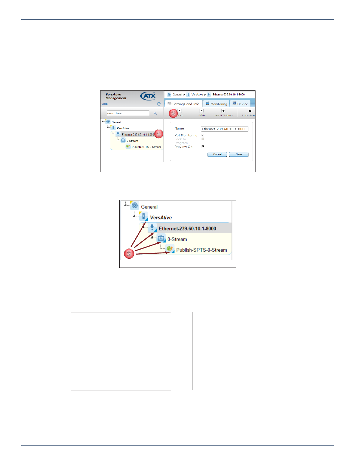
1. In the Tree View, click to select the Resource to be started, Figure 4-14.
2. Click the Start button on the Tool Bar (or the Right Click Menu).
Figure 4-14: Start the Streaming Process
3. The Streaming starts and is indicated in the Tree View by small triangles in the lower right corner of all streaming
Element Icons, Figure 4-15.
4.7.1 Streaming Icon Indicators
When streaming starts, the icon for each element changes to show a small triangle to indicate that.
Before the streaming is started the icons appear without triangle indicator, Figure 4-16. Once streaming has begun, the
triangle appears in each icon, Figure 4-17.
Figure 4-15: Streaming Started
Figure 4-16: Streaming Stopped
4-10 VersAtive®Pro Enhanced – Operation Manual
Figure 4-17: Streaming Started
Page 37
ALARMS & EVENTS
3
4
123
4
3
4
1
2
5. Alarms & Events
Alarms are current issues that exist with the Device and are not persistent; these are cleared over time as issues are resolved.
Alarms are of a minor nature and do not affect or report on the streaming operation of the Device platform. Events are reported
on issues of a higher degree and are persistent; being saved until they are manually deleted.
5.1 Chapter Contents
• “Alarms”
• “Events”
• “Events History”
5.2 Alarms
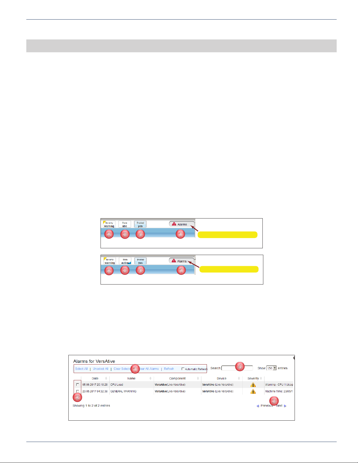
The Alarms Notication Panel is presented in the top right corner of the GUI, see Figure 5-1 and Figure 5-2.
1. Alarms Button - Opens the alarms window for review and deletion of reported alarms.
2. Severity - Indication of the severity of the current alarm condition.
3. State - Reports on the state of the Device platform, either Active (Streaming and note the small blue triangle in the
icon, Figure 5-2) or Idle.
4. Enabled - Reports on the Device, Enabled or Disabled (it is possible to disable the device from the right click menu
in Tree View).
CHAPTER 5: ALARMS & EVENTS
5.2.1 Reviewing Alarms
Open the Alarms window by clicking the Alarms Button, top right corner of the GUI, Figure 5-1 (1). The Alarms window opens
and displays the current alarms, Figure 5-3.
1. Select the desired action from the actions list. “Clear All Alarms” action will directly delete all alarms with a warning.
2. Item’s selection boxes become ticked or manually select each item for action.
3. Review a long list of alarms with the “Previous/Next’” action controls.
4. Search an alarm condition with criteria. The list is dynamically refreshed with the items matching the entered string.
12
Figure 5-1: Alarms Notication Panel - Device Idle
Figure 5-2: Alarms Notication Panel - Device Streaming
Click to Access Alarms
Click to Access Alarms
Figure 5-3: Reviewing Alarms
VersAtive®Pro Enhanced – Operation Manual 5-1
Page 38
CHAPTER 5: ALARMS & EVENTS
1
2
4
5
6
7
8
5.3 Events
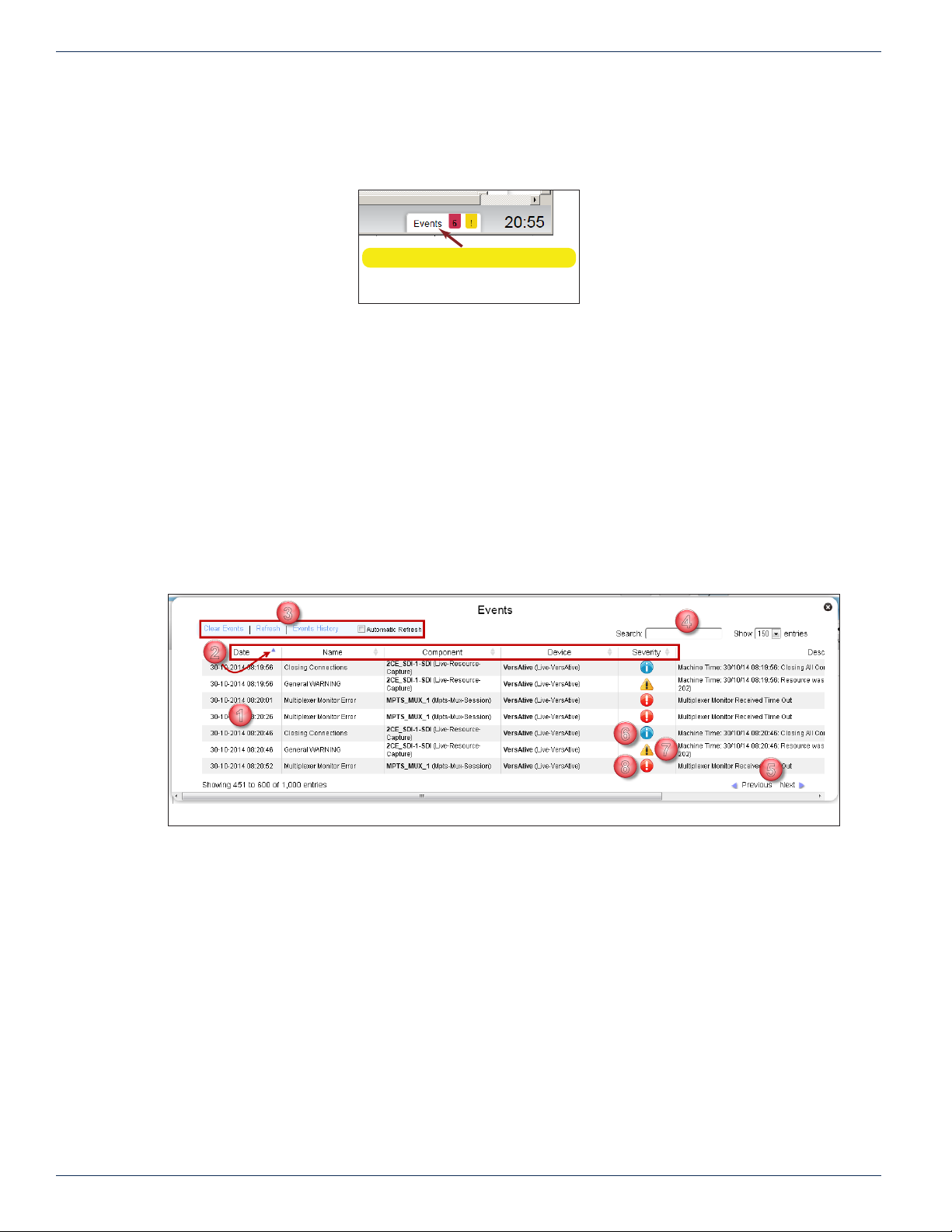
The Events Notication Panel in the GUI is at the lower right corner, Figure 5-4, and clicking it opens a new Events window,
see Figure 5-5.
5.3.1 Reviewing Events
Open the Events log window shown in Figure 5-5, by clicking the Events Panel Button, Figure 5-4.
1. Events are displayed by default in chronological order, most recent rst. Use scroll bars or mouse wheel to view list
extents.
2. The sort ordering can be changed by clicking the column header. All headers toggle and sort the list between ‘top
down’ & ‘bottom down’ when clicked.
3. Click the control actions to clear events or open “Events History” window.
4. Search an alarm condition with criteria. The list is dynamically refreshed with the items matching the entered string.
5. Review a long list of alarms with the “Previous/Next’” action controls.
6. Severity - Information Only. Does not affect streaming
7. Severity - Warning. Potentially affects streaming.
8. Severity - Error. Event affecting streaming.
Click to Access Events Log
Figure 5-4: Events Notications
3
Figure 5-5: Reviewing Events
5-2 VersAtive®Pro Enhanced – Operation Manual
Page 39
5.4 Events History
1
2
3
4
5
6
7
8
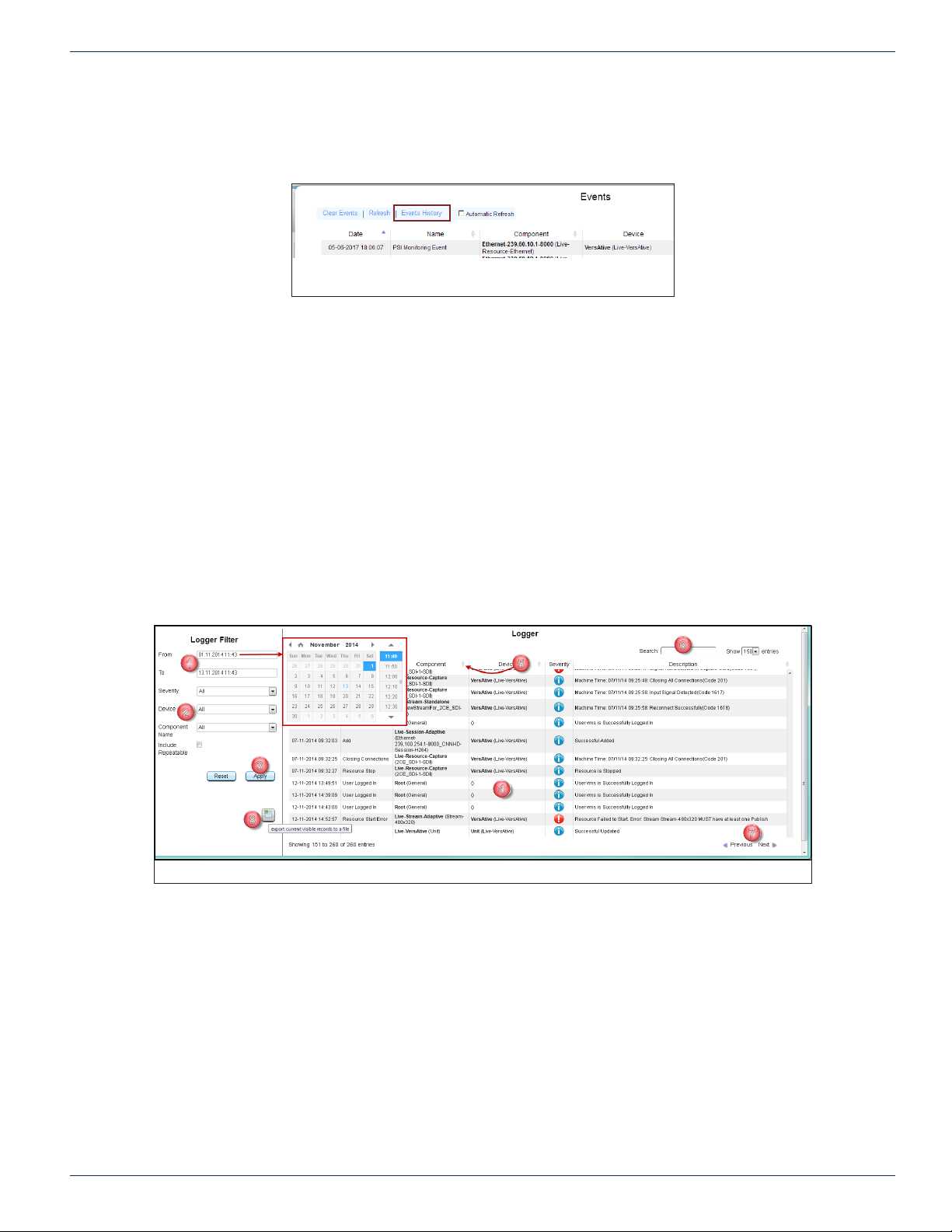
Open the “Events History” by clicking the Events History link, Figure 5-6. The new browser tab, Figure 5-7, shows alarm
history which may be manipulated or searched.
5.4.1 Reviewing Events History
Events History is presented in a new browser tab, see Figure 5-7.
1. Choose a date range by clicking the “From/To” dialogs to open a date selector in which the desired date range may
be specied.
2. Select desired ‘Severity’, ‘Device’ or ‘Component’ levels to be displayed.
3. Clicking Apply button initiates the action. All lter settings require Apply button to initiate action.
4. Events are displayed by default in chronological order, most recent rst. Use scroll bars or mouse wheel to view list
extents.
5. The sort ordering can be changed by clicking the column header. All headers toggle and sort the list between ‘top
down’ & ‘bottom down’ when clicked.
6. Search an alarm condition in the current displayed list with a string. The list is dynamically refreshed with the items
matching the entered string.
7. Review a long list of alarms with the “Previous/Next’” action controls.
8. Download a copy of the current visible records in a spreadsheet compatible le.
CHAPTER 5: ALARMS & EVENTS
Figure 5-6: Select Events History
Figure 5-7: Reviewing Events History
VersAtive®Pro Enhanced – Operation Manual 5-3
Page 40

CHAPTER 5: ALARMS & EVENTS
This page intentionally left blank.
5-4 VersAtive®Pro Enhanced – Operation Manual
Page 41
MONITORING
2
3
4
5
6
7
1
6. Monitoring
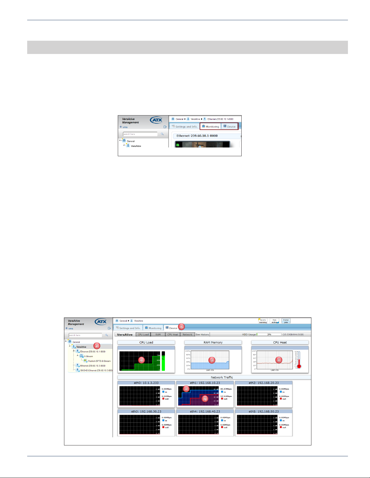
There are two basic types of monitoring available by clicking the Monitoring tab or Device tab, Figure 6-1.
Device Monitoring - Select Device tab to Display histograms of the performance and load factors of the system hardware.
Resource Monitoring - Select Monitoring tab to provide a live video display of any Ethernet Resource.
6.1 Chapter Contents
• “Monitoring the Device”
• “Preview or Monitor Resources”
• “Displaying Stream Information”
CHAPTER 6: MONITORING
Figure 6-1: Monitoring and Device Tabs
6.2 Monitoring the Device
The Device may be monitored at a Hardware level, which is the underlying machine motherboard.
1. In Tree View, click the Device icon, Figure 6-2.
2. Click to select the Device tab.
3. CPU Load - The histogram of average CPU load over the last 30 seconds displayed in Green.
4. RAM - The histogram of average RAM usage over the last 40 seconds.
5. CPU Heat - The histogram of average CPU temperature over the last 40 seconds.
6. Network Trafc Input- Network Interface input trafc load is displayed in Blue.
7. Network Trafc Output- Network Interface output trafc load is displayed in Red.
Note: The Monitoring starts recording when the Device tab is selected.
Figure 6-2: Monitoring the Device
VersAtive®Pro Enhanced – Operation Manual 6-1
Page 42
CHAPTER 6: MONITORING
1
2
3
6.2.1 Longer Term Device Monitoring
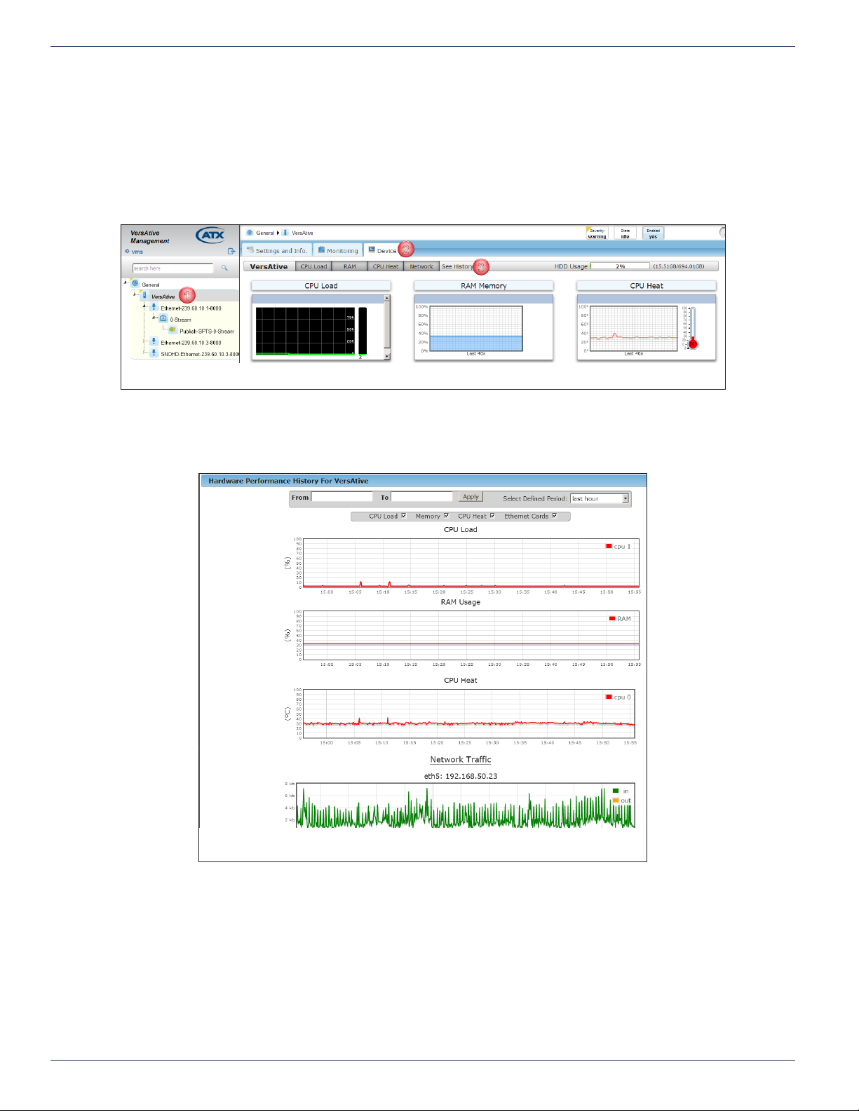
The default view for the monitor period is the last 40 seconds, but a longer term histogram is saved in each Device. This is
accessed from the Device tab by clicking the See History link shown in Figure 6-3.
1. In Tree View, click the Device Icon.
2. Click to select the Device tab.
3. Click the See History tab.
A number of options may be selected to determine the length of history. The exact dates may be selected from the calendar
by clicking in the From and To windows, Figure 6-4. Preset time periods of from the last hour up to last 2 weeks may also
be selected.
Figure 6-3: Monitor the Device History
Figure 6-4: Monitor a Device Histogram
6-2 VersAtive®Pro Enhanced – Operation Manual
Page 43
6.3 Preview or Monitor Resources
The Preview monitoring function for each Resource is enabled by default, Figure 6-5, but may be disabled at each individual
Resource by unticking the Preview On box with the Settings and Info tab selected, and then clicking Save.
Previewing resources uses some of the platform CPU cycles although usually an insignicant amount. It is however possible
that the Device functions are running low on CPU cycles witnessed by high CPU load, see “Monitoring the Device” on page
6-1, and it may be judged that Preview functionality can be sacriced in order to maximize transcoding power. In this case a
user may disable Preview to lower CPU load.
CHAPTER 6: MONITORING
Figure 6-5: Preview Enabled
6.3.1 Video Preview
Any single Resource may be Previewed to determine the content or quality of the ingested video before the content transcoding
is started. Video is displayed at 5 frames/sec. Preview of audio is not supported.
Adobe Flash is required for the preview function and some browsers or optional settings within browsers may require that you
specically allow Flash Player to run due to security concerns. In Figure 6-6 we show an example of what you may see when
Preview is selected but your browser may be slightly different. The preview window may be grayed or blacked out requiring
you to click to activate Flash.
Click to run Adobe Flash Player
Figure 6-6: Click to Activate Adobe® Flash
®
VersAtive®Pro Enhanced – Operation Manual 6-3
Page 44
CHAPTER 6: MONITORING
1
3
4
2
5
6
7
8
9
6.3.2 Preview a Resource
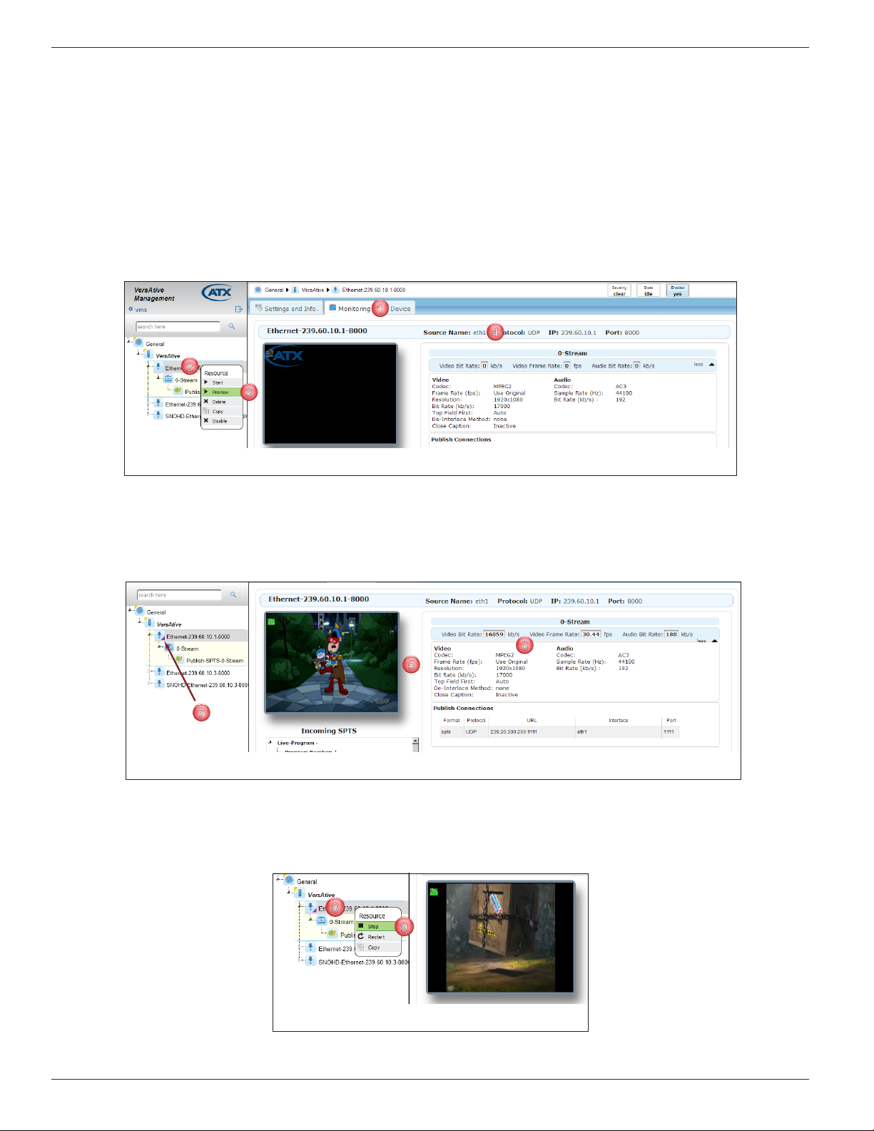
Preview of a resource may only be done before streaming of the Resource is started.
Procedure
This procedure explains how to preview a Resource.
1. Click to select the Monitoring tab, Figure 6-7.
2. From the Tree View, Right Click the Resource to be Previewed.
3. Select Preview in the menu.
4. Properties of the Resource are displayed in the Pane View window.
Figure 6-7: Select a Resource to Preview
5. The video is soon presented in a window, Figure 6-8.
6. Stream parameters such as bit rates are displayed in the Pane View.
7. The Resource in Tree View shows a purple triangle indicating Preview monitoring is active, Figure 6-8. This must be
manually stopped before adding SPTS Streams or starting transcoding.
Figure 6-8: Resource Monitor Indicator
8. To stop the Preview, Right Click the Monitored Resource to open the menu, Figure 6-9.
9. Click to select Stop in the menu.
• The Resource stops streaming to the monitor window.
Figure 6-9: Stop Resource Monitoring
6-4 VersAtive®Pro Enhanced – Operation Manual
Page 45
6.3.3 Multiple Resource Monitoring
1
2
3
2
3
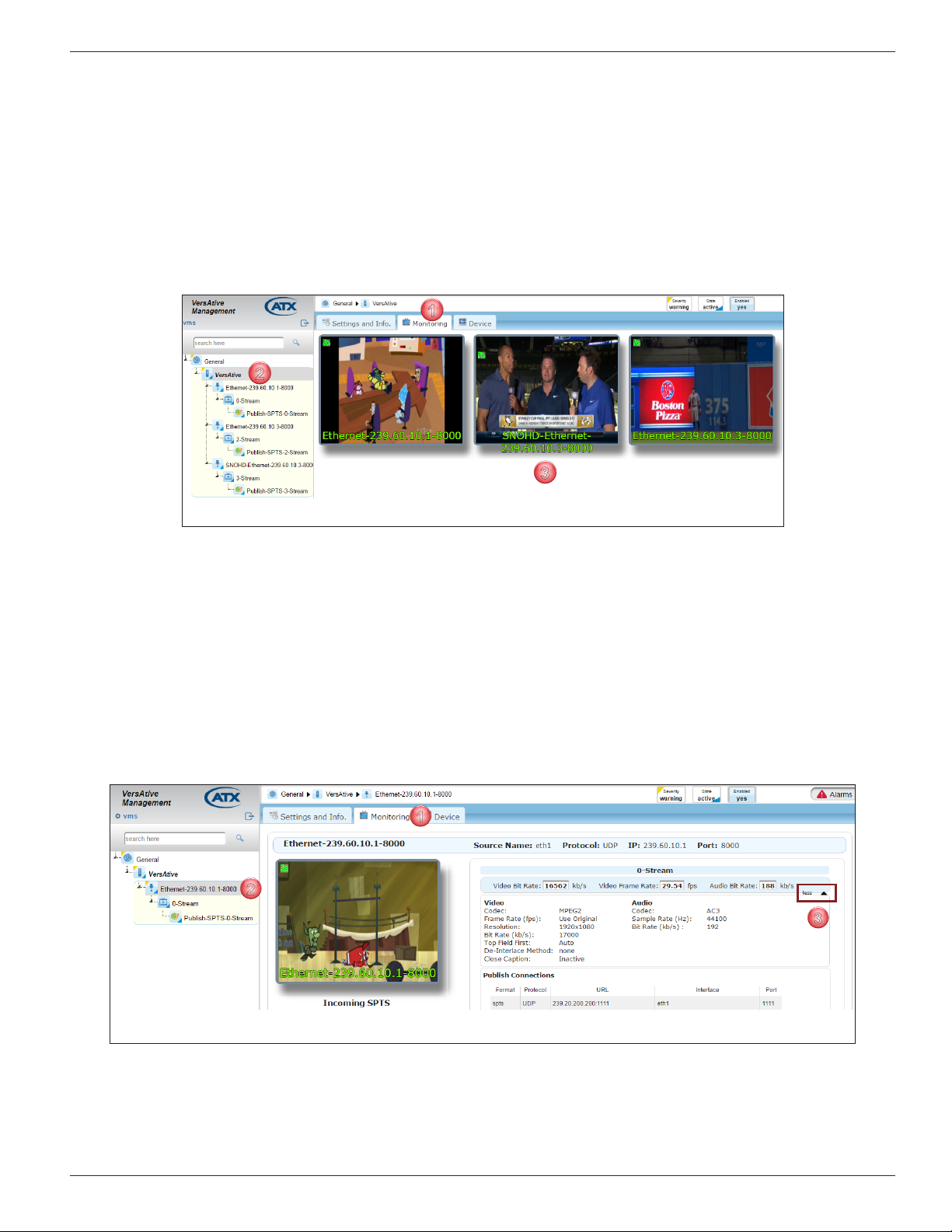
All available Resources may be monitored on a single page. Video is displayed at 5 frames/sec. For audio monitoring, see
“6.3.2 Preview a Resource”.
1. Click to select the Monitoring tab, Figure 6-10.
2. From the Tree View, click the Device.
3. All Resources which have active output streams are displayed in the Pane View.
• There is no accompanying audio.
• To stop the monitoring, click away from the Device Or Monitor tab.
CHAPTER 6: MONITORING
Figure 6-10: Monitor Device Resources
6.4 Displaying Stream Information
During monitoring, there is full stream information available that is displayed by default but this may be turned off.
6.4.1 View Less Stream Information
While the Monitoring tab is selected, expanded stream information shown in the Pane View window is the default setting.
Turning off Expanded Information
1. Click the Monitoring tab if it isn’t already selected.
2. From the Tree View, click to select the Resource to be monitored, Figure 6-11.
3. Click Less.
4. Expanded Stream Information is not displayed (example shows before clicking Less).
1
Figure 6-11: View Less Resource Stream Information
VersAtive®Pro Enhanced – Operation Manual 6-5
Page 46

CHAPTER 6: MONITORING
This page intentionally left blank.
6-6 VersAtive®Pro Enhanced – Operation Manual
Page 47

MKIP SYSTEM SHELL
7. Mkip System Shell
The Device Ethernet IP Addresses may be completely congured from within the GUI but some features may also be congured
with the built in shell interface which is called MKIP. The MKIP interface is only accessed by connecting a mouse, keyboard
and monitor physically to the server; remote access is not supported. This chapter explains the conguration that is available
within the shell.
7.1 Chapter Contents
• “Connect Using Monitor, Keyboard and Mouse”
• “MKIP Shell Menu”
• “Menu - Display”
• “Menu - Set Network.”
• “Menu - Ping”
• “Menu - TCP Dump”
• “Menu - Eth0 Set Default”
• “Menu - Date/Time”
• “Menu - Restart”
• “Menu - Shutdown”
• “Menu - Authentication Mode”
CHAPTER 7: MKIP SYSTEM SHELL
7.2 Connect Using Monitor, Keyboard and Mouse
1. With the Device turned off, connect a VGA monitor to the rear panel VGA port.
2. Connect a USB keyboard and mouse to any of the Device USB ports.
3. Turn on the Device.
The monitor screen will display messages from the Device boot-up application. Once the boot process has nished
and no further messages are scrolling up the screen, use the key combination Ctrl+Alt+F2 to access the IP settings
screen.
◦ The monitor screen, see Figure 7-1, will display login as:
4. Use the following:
Username: mkip
Password: 123456
Figure 7-1: mkip Shell Login Screen
After a short delay, you will be presented with the MKIP System Settings menu, Figure 7-2.
Figure 7-2: MKIP System Menu
VersAtive®Pro Enhanced – Operation Manual 7-1
Page 48
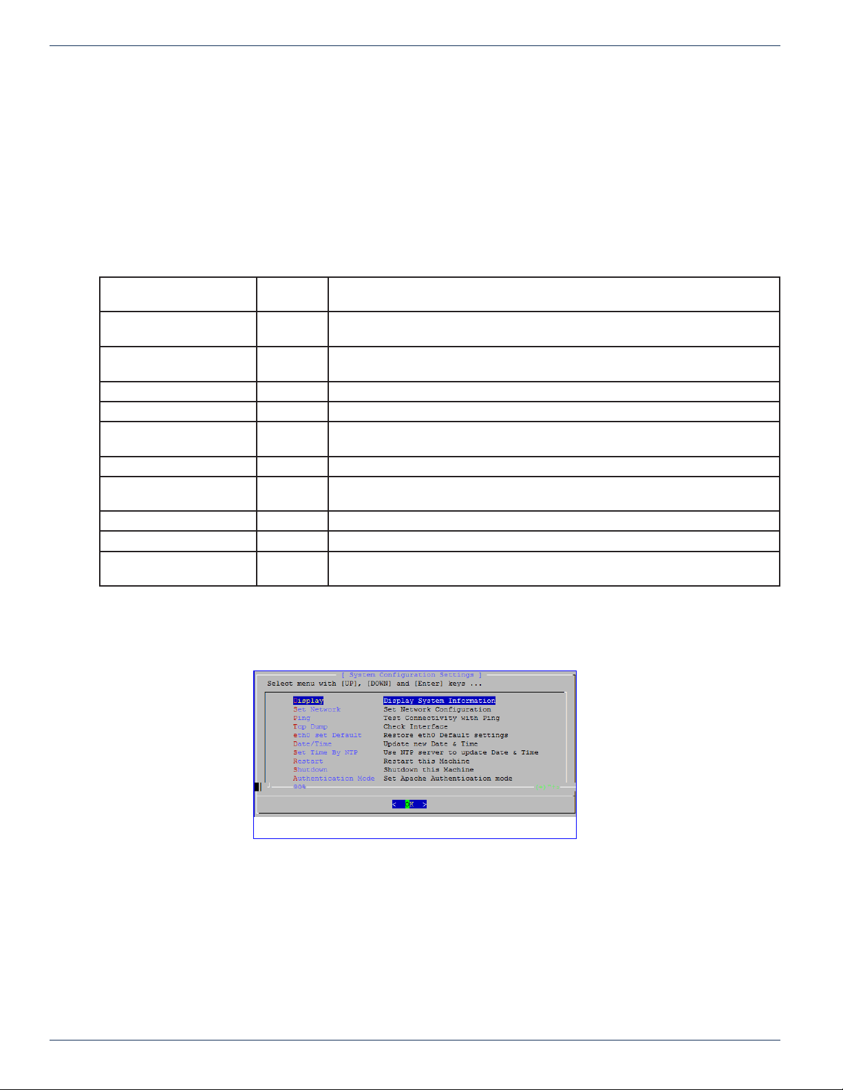
CHAPTER 7: MKIP SYSTEM SHELL
5. Navigate the shell menu in three ways:
◦ Type the letter appearing in red font
◦ Use the keyboard up/down arrows
◦ Use a mouse left click
◦ To select, either click OK or use keyboard Return/Enter
7.3 MKIP Shell Menu
There are a number of operations that may be performed at the mkip system shell menu as described in Table 7.3a.
Table 7.3a: MKIP System Shell Menu Choices
Setting
Display D Displays system information such as all the IP addresses (including virtual
Set Network S Change the IP address settings of eth1, eth2, eth3 and eth4 (not eth0). Also
Ping P PING is a network interface utility to test connectivity to other network Devices.
TCP dump T Allows the user to check source multicasts on each of the eth ports.
eth0 set Default e Restores all eth0 settings to their Factory Setting with the management IP address
Date and Time D Enter date and time manually. This disables NTP updates.
Set Time by NTP S Enter NTP server address to automatically set date and time and over-ride any
Restart R Causes the server to reboot.
Shutdown S Causes the server to immediately shutdown and not restart.
Authentication Mode A Sets the Apache Authentication mode between Local Authentication (Default) and
Keyboard
shortcut
Description
addresses), subnet masks, gateways and physical MAC addresses.
enables the addition of virtual interfaces, which may used for VLAN tagging.
(eth0) set to 192.168.0.23.
manual settings. Time zone locale is set here also.
use of a RADIUS Server.
7.4 Menu - Display
1. Click Display to choose to display system IP addresses, Figure 7-3.
Figure 7-3: MKIP System Conguration Settings Menu
7-2 VersAtive®Pro Enhanced – Operation Manual
Page 49
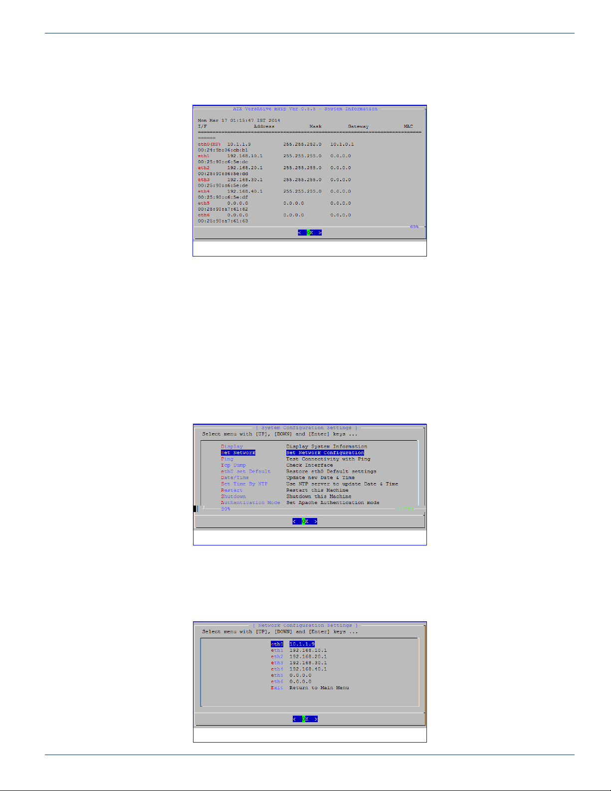
2. Click or select OK to open the information window, Figure 7-4.
3. Click OK again to return to the System Conguration Settings Menu.
7.5 Menu - Set Network.
Set all physical Ethernet network IP addresses here (except for eth0 which is only set to default IP address from MKIP. Other
settings for eth0 must be set from the GUI).
CHAPTER 7: MKIP SYSTEM SHELL
Figure 7-4: Display System Information
NOTE: For eth0 settings, only the GUI may be used to set eth0 IP parameters. MKIP may only
be used to set eth0 to default IP address of 192.168.0.23.
Setting the Management IP address
1. Select Set Network, Figure 7-5.
Figure 7-5: Set Network
2. Click OK to open the Network Conguration Settings page, Figure 7-6.
3. The eth0 network is selected; click OK to set the eth0 IP Address (the Management port) or arrow down to select
another port. Setting the network is a series of pages so click OK each time to proceed to the next page in the series.
Figure 7-6: Choose Network
VersAtive®Pro Enhanced – Operation Manual 7-3
Page 50
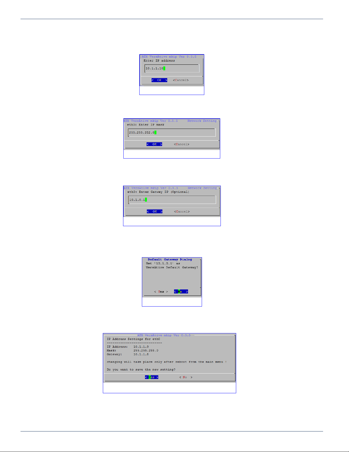
CHAPTER 7: MKIP SYSTEM SHELL
4. Enter the desired IP address, Figure 7-7.
5. Set Subnet mask, Figure 7-8.
6. Setting the Gateway IP address is optional, Figure 7-9. This is usually the router providing internet access but if there
is no router, do not enter any IP address.
Figure 7-7: Set IP Address
Figure 7-8: Set Subnet Mask
Figure 7-9: Set Gateway
7. If the default gateway IP address was set and this interface default gateway is not already the current machine default
gateway, you are prompted next to set that, Figure 7-10. Select yes to set it as the default or no.
Figure 7-10: Set Gateway
8. When nished and you accept the changes, Figure 7-11, the server will reboot.
9. Reconnect on the new IP address, if changed.
Figure 7-11: Save Settings
7-4 VersAtive®Pro Enhanced – Operation Manual
Page 51
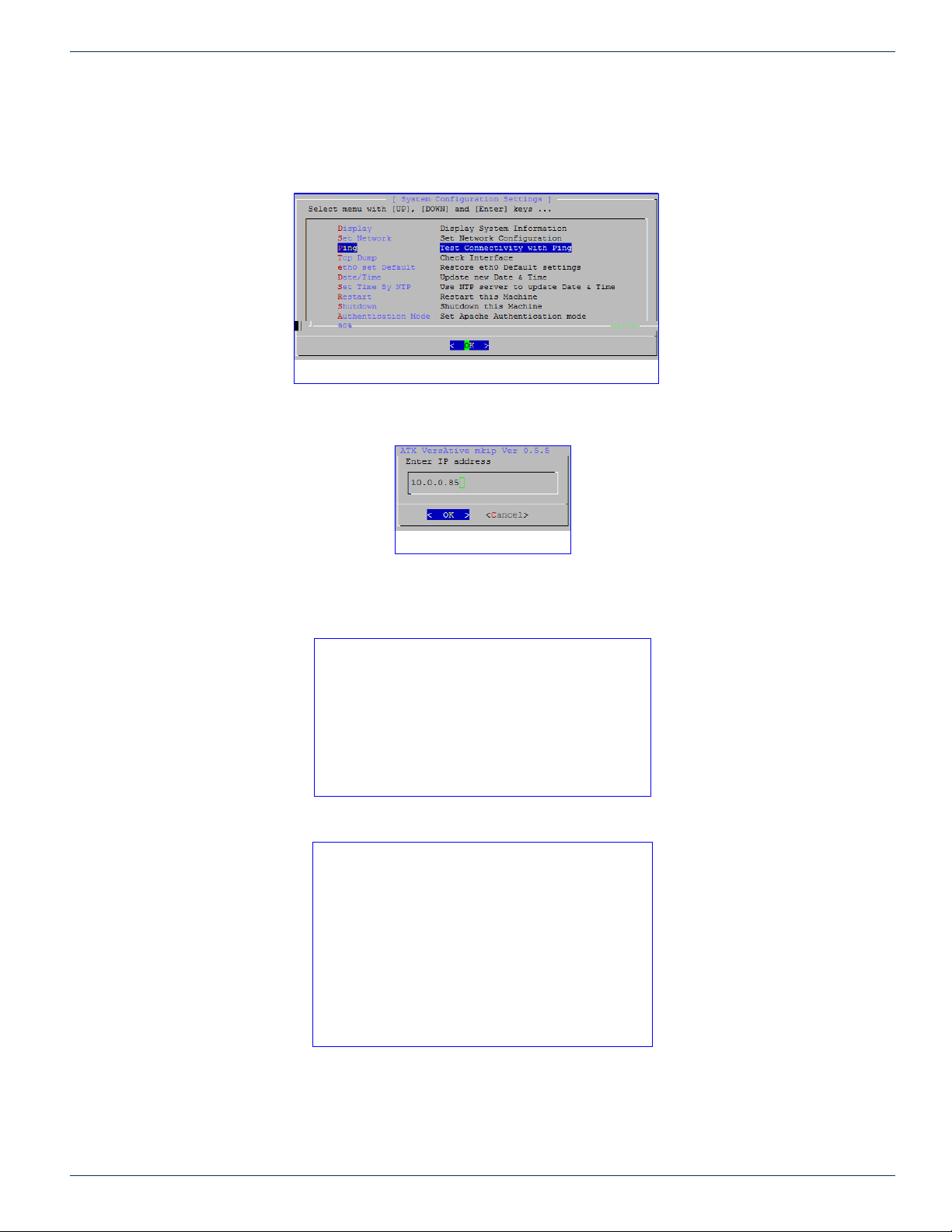
7.6 Menu - Ping
The Ping command may be used to test connectivity between the Device and a remote machine.
1. Select Ping and click OK, Figure 7-12.
2. Enter a target address on the network, Figure 7-13.
CHAPTER 7: MKIP SYSTEM SHELL
Figure 7-12: Ping
Figure 7-13: Enter Target IP
3. Depending on the ability to reach the destination target address, one of the following results will be obtained.
◦ If target is not reachable, Figure 7-14.
Figure 7-14: Output for no Connectivity
◦ If target is reachable, Figure 7-15.
Figure 7-15: Output for Connectivity
4. Strike any key to return to the menu.
VersAtive®Pro Enhanced – Operation Manual 7-5
Page 52
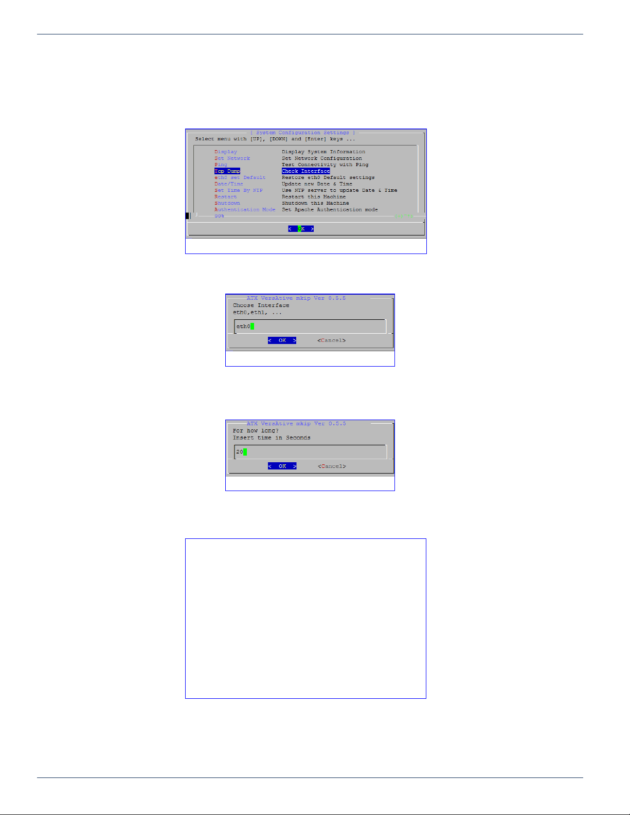
CHAPTER 7: MKIP SYSTEM SHELL
7.7 Menu - TCP Dump
Use this option to obtain a TCP protocol dump for troubleshooting interface issues and connectivity.
1. Select TCP Dump from the menu, Figure 7-16
2. Specify a target interface by typing the interface name, Figure 7-17. Click OK.
Figure 7-16: Select ‘TCP Dump’
Figure 7-17: Select an Interface
3. A time limit for this dump must be specied in seconds, Figure 7-18. Click OK.
Figure 7-18: Enter a time limit
4. Receive the output of the TCP dump on your terminal session screen, Figure 7-19.
Figure 7-19: View the Dump Data
7-6 VersAtive®Pro Enhanced – Operation Manual
Page 53
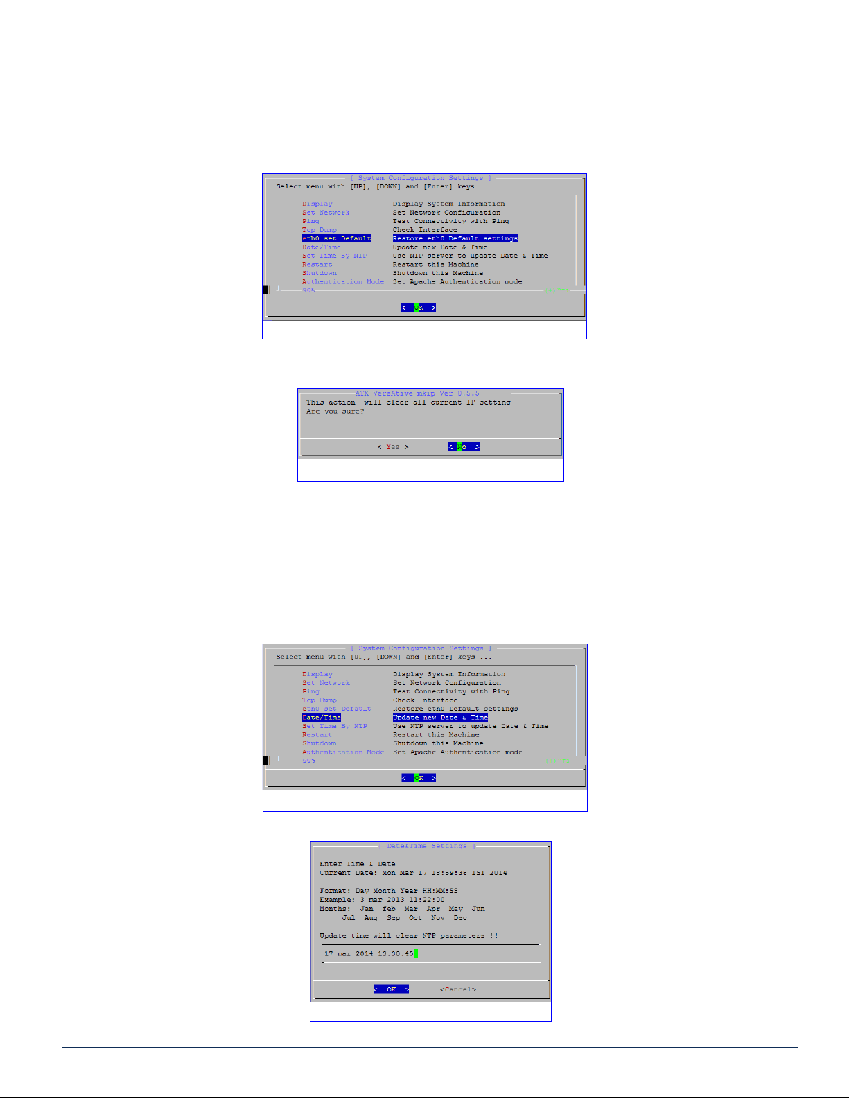
7.8 Menu - Eth0 Set Default
The current settings of the MGMNT management Interface eth0 may be set to factory default 192.168.0.23 with this option.
1. Select eth0 Set Default from the menu, Figure 7-20.
2. Conrm action, click Yes, Figure 7-21.
CHAPTER 7: MKIP SYSTEM SHELL
Figure 7-20: Select ‘eth0 Set Default’
3. The change takes place after a reboot. Log in again using 192.168.0.23.
7.9 Menu - Date/Time
The Device time may be set manually from this option. If a date and time is entered, the NTP server IP address, if entered,
will be removed.
1. Select Date/Time from the menu, Figure 7-22.
Figure 7-21: Conrm Restore eth0 to Default
Figure 7-22: Select ‘Date/Time’
Figure 7-23: Enter Date/Time in correct format
VersAtive®Pro Enhanced – Operation Manual 7-7
Page 54
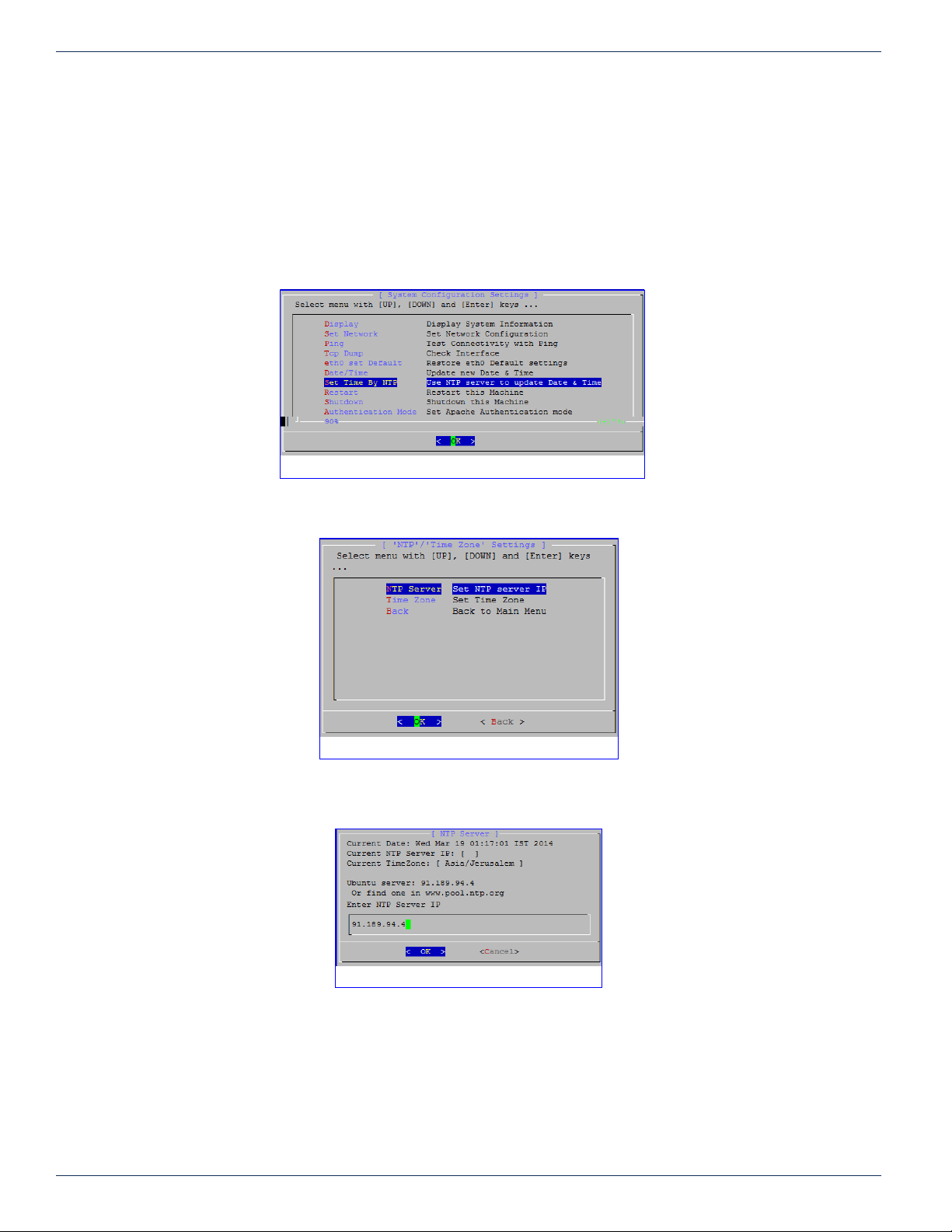
CHAPTER 7: MKIP SYSTEM SHELL
2. Enter the time and date in the format: Day Month Year HH:MM:SS (Example 3 mar 2013 11:22:00), Figure 7-23.
Click OK.
3. Time will be set to the specied time and any NTP server IP addresses will be cleared.
Menu - Set Time by NTP
The Device time may be set to be updated by an NTP server. This is the only way to dene the NTP server. It cannot be set
from the GUI.
1. Select Set Time By NTP from the menu, Figure 7-24.
Figure 7-24: Select ‘Set Time By NTP’
2. Enter the IP address of the NTP server. Do not use the url, Figure 7-25. Click OK.
Figure 7-25: Choose ‘Set NTP Server IP’
3. In the open dialog shown in Figure 7-26, note the time zone that is currently set. If this time zone is incorrect then
after setting the NTP IP address, you must also set the Time Zone from the menu next.
Figure 7-26: Enter the IP address
4. If the time zone was incorrect, select Set Time By NTP again from the menu, Figure 7-24. This time choose Time
Zone, Figure 7-25.
7-8 VersAtive®Pro Enhanced – Operation Manual
Page 55
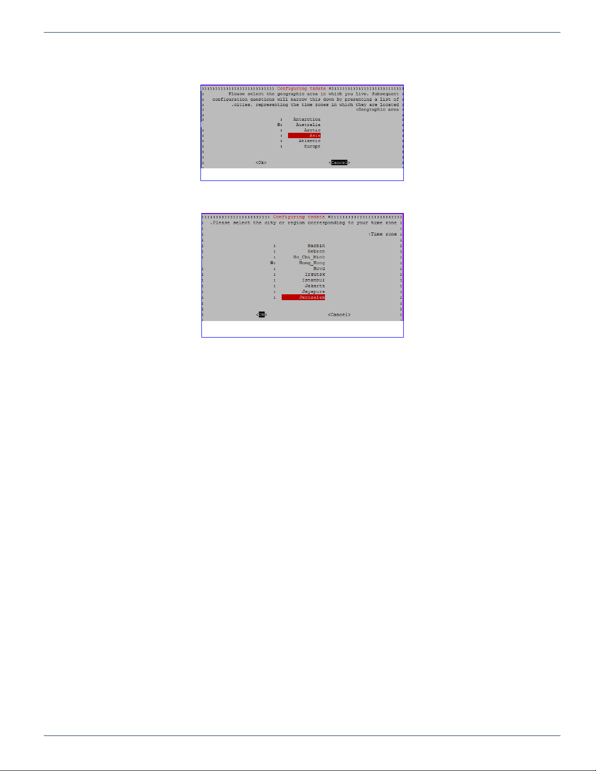
CHAPTER 7: MKIP SYSTEM SHELL
5. Choose the geographic region for the time zone of the Device, Figure 7-27, then click OK.
Figure 7-27: Chose Geographic Area
6. Choose the local region of the Device, Figure 7-28. Click OK.
7. Time will be automatically updated from the dened server.
7.10 Menu - Restart
Shutdown and restart the server from this option.
7.11 Menu - Shutdown
Shutdown the server from this option. The server will not restart.
7.12 Menu - Authentication Mode
Local Authentication
Only GUI authentication with username and password is supported.
In this mode the User name and the Password are required. (Both the Apache2 username/password and mkip password).
Figure 7-28: Choose Local Region
VersAtive®Pro Enhanced – Operation Manual 7-9
Page 56

CHAPTER 7: MKIP SYSTEM SHELL
This page intentionally left blank.
7-10 VersAtive®Pro Enhanced – Operation Manual
Page 57

SERVICE & SUPPORT
8. Service & Support
8.1 Contact ATX Networks
Please contact ATX Technical Support for assistance with any ATX products. Please contact ATX Customer Service to obtain
a valid RMA number for any ATX products that require service and are in or out-of-warranty before returning a failed module
to the factory.
DIGITAL VIDEO TECHNICAL SUPPORT
Tel: (905) 428-6068
Toll Free: (800) 565-7488 (USA & Canada only)
► Press *3 for Technical Support
►Then press 1 for Digital Video Products (DVIS, DigiVu, UCrypt, VersAtivePro, DigiStream)
Email: [email protected]
CUSTOMER SERVICE
ATX Networks
1-501 Clements Road West
Ajax, ON L1S 7H4 Canada
CHAPTER 8: SERVICE & SUPPORT
Tel: (905) 428-6068
Toll Free: (800) 565-7488 (USA & Canada only)
► Press *1 for Customer Service
Fax: (905) 427-1964
Toll Free Fax: (866) 427-1964 (USA & Canada only)
Web: www.atxnetworks.com
Email: [email protected]
8.2 Warranty Information
All of ATX Networks’ products have a 1-year warranty that covers manufacturer’s defects or failures.
VersAtive®Pro Enhanced – Operation Manual 8-1
Page 58

1-501 Clements Road West, Ajax, ON L1S 7H4 Canada
Tel +1 (905) 428-6068 Toll Free +1 (800) 565-7488
Fax +1 (905) 427-1964 Toll Free Fax +1 (866) 427-1964
www.atxnetworks.com [email protected]
Printed in Canada Rev. 08/17 (ANW1223)
 Loading...