

ATX ULi M1689 User Manual

ULi M1689
ATX Motherboard
User’s Guide

Declaration of Conformity
According to 47 CFR, Parts 2 and 15 of the FCC Rules
The following designated product:
EQUIPMENT: MAINBOARD
is a Class B digital device that complies with 47 CFR Parts 2 and 15 of the FCC
Rules. Operation is subject to the following two conditions:
1. This device may not cause harmful interference.
2. This device must accept any interference received, including interference that
may cause undesired operation.
This declaration is given to the manufacturer:
CHAINTECH AMERICA CORP.
4427 Enterprise St. Fremont, CA 94538, U.S.A.
http://www.chaintechusa.com
Chaintech President: Simon Ho
Signature:

Federal Communications Commission Statement
This device complies with FCC Rules Part 15. Operation is subject to the following two conditions:
* This device may not cause harmful interference.
* This device must accept any interference received, including interference that may cause undesired operation.
This equipment has been tested and found to comply with the limits for a Class B digital device, pursuant to
Part 15 of the FCC Rules. These limits are designed to provide reasonable protection against harmful interference
in a residential installation. This equipment generates, uses, and can radiate radio frequency energy. If this
equipment is not installed and used in accordance with the manufacturer's instructions, it may cause harmful
interference to radio communications. However, there is no guarantee that interference will not occur in a
particular installation. If this equipment does cause harmful interference to radio or television reception, which can
be determined by turning the equipment off and on, the user is encouraged to try to correct the interference by one
or more of the following measures:
* Reorient or relocate the receiving antenna.
* Increase the separation between the equipment and receiver.
* Connect the equipment to an outlet on a circuit different from that to which the receiver is connected.
* Consult the dealer or an experienced radio/TV technician for help.
The use of shielded cables for connection of the monitor to the graphics card is required to assure
compliance with FCC regulations. Changes or modifications to this unit not expressly approved by the party
responsible for compliance could void the user's authority to operate this equipment.
Canadian Department of Communications Statement
This digital apparatus does not exceed the Class B limits for audio noise emissions from digital apparatuses
set out in the Radio Interference Regulations of the Canadian Department of Communications.
Manufacturer's Disclaimer Statement
The information in this document is subject to change without notice and does not represent a commitment
on the part of the vendor. No warranty or representation, either expressed or implied, is made with respect to the
quality, accuracy or fitness for any particular purpose of this document. The manufacturer reserves the right to
make changes to the content of this document and/or the products associated with it at any time without obligation
to notify any person or organization of such changes. In no event will the manufacturer be liable for direct, indirect,
special, incidental or consequential damages arising out of the use or inability to use this product or documentation,
even if advised of the possibility of such damages. This document contains materials protected by copyright. All
rights are reserved. No part of this manual may be reproduced or transmitted in any form, by any means or for any
purpose without expressed written consent of its authors. Product names appearing in this document are mentioned
for identification purposes only. All trademarks, product names or brand names appearing in this document are
registered property of their respective owners.
Printed in Taiwan.
JAN 2004
OST-CONSUMER
RECYCLED PAPER
100%

TABLE OF CONTENTS
Chapter 1 Introduction............................................................1
1-1 Specifications...............................................................................................1
1-2 Package Contents.........................................................................................2
1-3 Back Panel...................................................................................................3
1-4 Motherboard Layout.....................................................................................3
Chapter 2 Hardware Setup.....................................................4
2-1 PC D.I.Y. Assembly Instructions...................................................................4
2-2 自行組裝電腦之作業指導重點 (Chinese)..................................................6
2-3 Français Instructions de montage du PC D.I.Y (French)................................8
2-4 Deutsch PC D.I.Y.-Montageanleitung (German).........................................10
2-5 Самостоятельная сборка ПК (Russian)....................................................12
2-6 PC D. I. Y. 조립 설명 (Korean)...............................................................14
2-7 Connector and Jumper Settings...................................................................16
Chapter 3 Phoenix Award BIOS Setup Utility.....................20
3-1 Entering Phoenix-AwardBIOS CMOS Setup Utility...................................20
3-2 Standard CMOS Features...........................................................................20
3-3 Advanced BIOS Features............................................................................21
3-5 Integrated Peripherals.................................................................................28
3-6 Power Management Setup..........................................................................32
3-7 PNP/PCI Configurations.............................................................................33
3-8 PC Health Status.........................................................................................34
3-9 Frequency/Voltage Control.........................................................................34
3-10 Load Optimized Defaults..........................................................................35
3-11 Set Password............................................................................................35
3-12 Save and Exit Setup..................................................................................36
3-13 Exit Without Saving.................................................................................36
Chapter 4 Software................................................................37
4-1 Driver Setup...............................................................................................37
Appendix.................................................................................42
How to Install Windows 2000/XP On a SATA Drive.........................................42
Chapter 1
1
Chapter 1 Introduction
1-1 Specifications
CPU
- Supports AMD Socket-939 Althon 64 / Sempron CPU
- Processor interface via 2000MT/s HyperTransport bus
Chipset
- ULi M1689
Memory
- Four 184- pin DDR DIMMs up to 4GB
- Supports Dual Channel DDR266/333/400 memory
Due to CPU specifications limitation, two DDR400 memory
modules inserted into DIMM1/3, three DDR400 into DIMM1/2/3,
or four DDR400 into DIMM1/2/3/4 is not recommended.
Expansion Slots
- One AGP slot for 8X/4X AGP
- Five 32-Bit PCI slots (v2.2 compliant)
5.1 Channel Audio
- With external high quality 5.1-channel AC’97 Codec
- Complete software driver supports for Windows OS
SATA
- Supports four native SATA 1.5Gb/s devices
- Hot-swap capability, allowing disks to be changed without powering down the
system.
- Supports SATA ATAPI devices
IDE
- Supports 2 UltraDMA-66/100/133 IDE Ports
FDD
- One FDD connector supports up to 2.88 MB
USB 2.0
- Built-in M1689 supports total 8 USB 2.0/1.1 ports
- Supports USB 2.0 High-Speed Device @480 Mb/s Transfer Rates

Chapter 1
2
Fast Ethernet
- Supports 10/100Mb Fast Ethernet with external Realtek PHY
Boot-Block Flash ROM
- Award system BIOS supports PnP, APM, DMI, ACPI, & Multi-device
Booting features
Rear Panel I/O ports
- PS/2 Mouse and Keyboard port
- Four USB ports and one RJ45 connector
- Two 9-pin D-Sub male Serial ports
- 25-pin D-Sub female Parallel port
- Audio I/O jacks (Line-in, Line-out and Mic-in)
Internal I/O connectors
- Two 3x1 pin fan connectors
- Two 5x2 pin USB connectors for additional 4 USB ports
- 3x1 pin wake on LAN connector with housing
- Two 4x1 pin CD-in connectors
- 5x2 pin Front Audio connector
- 10x2 pin Front Panel connector
- 8x2 pin Game/Midi Port connector
- 20 pin ATX Power connector
- 4 pin ATX 12V Power connector
Form Factor
- ATX Form Factor 305mm x 200 mm
1-2 Package Contents
This product comes with the following components:
1. 1x Motherboard
2. 1x 40-Pin UDMA-100 IDE Cable
(Blue to motherboard, Gray to Master and Black to Slave)
3. 1x 34-Pin floppy Disk Drive Cable
4. 1x Serial ATA Cable
5. 1x SATA Power Cable
6. 1x User’s Guide
7. 1x Driver CD
8. 1x Value Pack 2005
Chapter 1
3
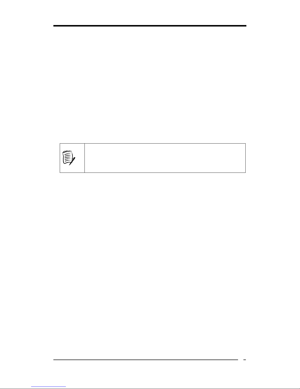
1-3 Back Panel
S1689
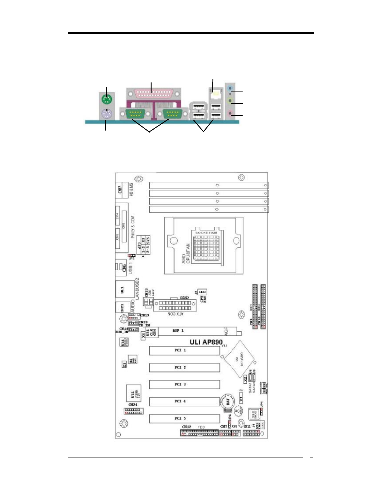
1-4 Motherboard Layout
PS/2
Mouse
PS/2
Keyboard
Printer Port
Serial ports
USB 2.0 ports
RJ-45 port
Line-In port
Line-Out port
Microphone
port
Chapter 2
4
Chapter 2 Hardware Setup
2-1 PC D.I.Y. Assembly Instructions
1. Jumper Setting:
Set the CPU External Clock, Frequency Ratio and the CPU voltage according to the
instruction printed on the manual or silkscreen printed on the mainboard.
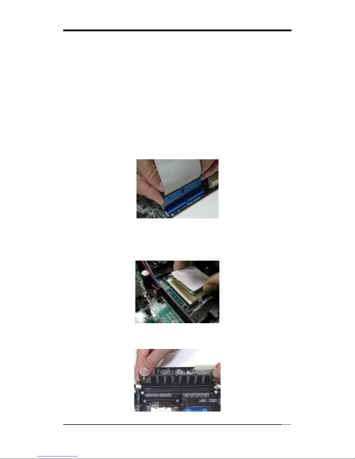
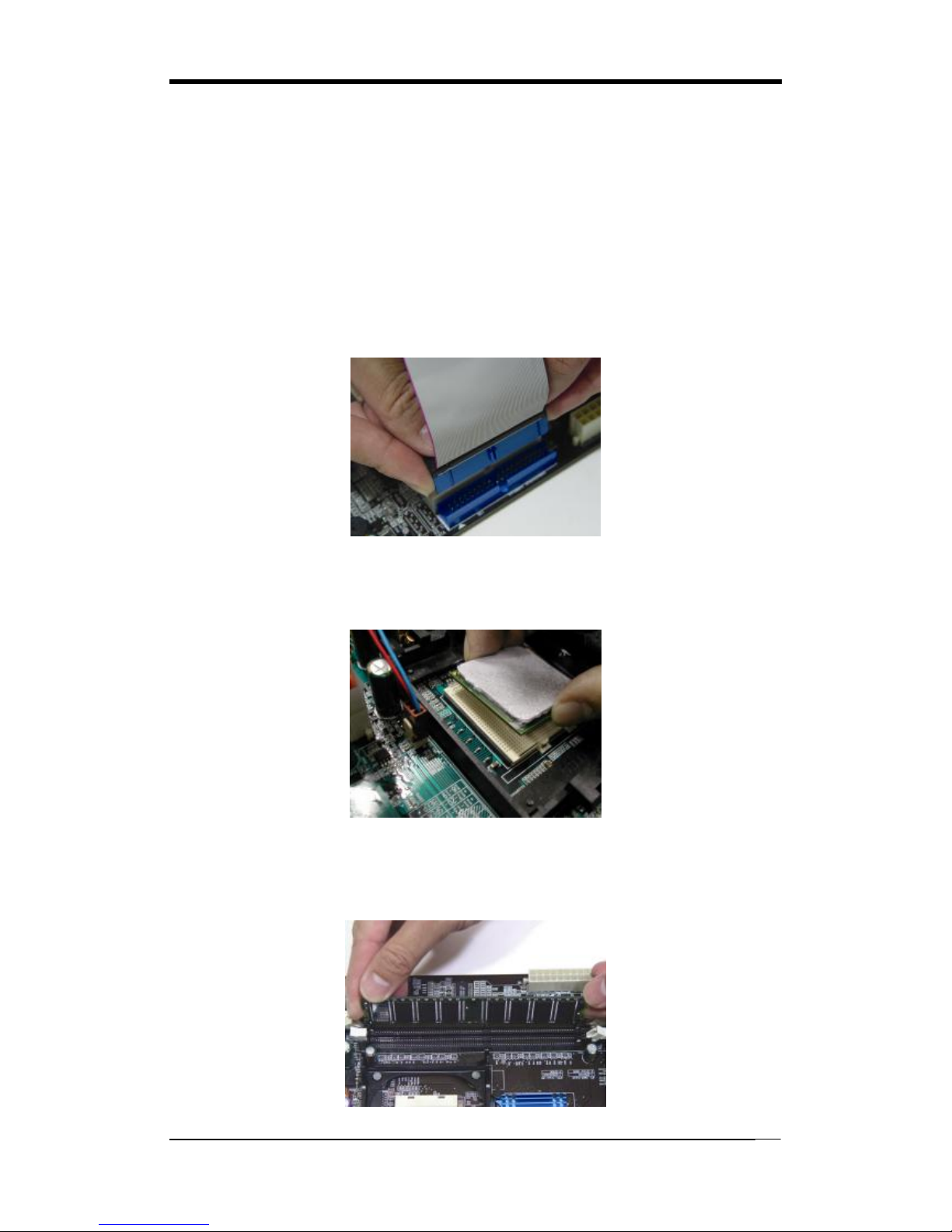
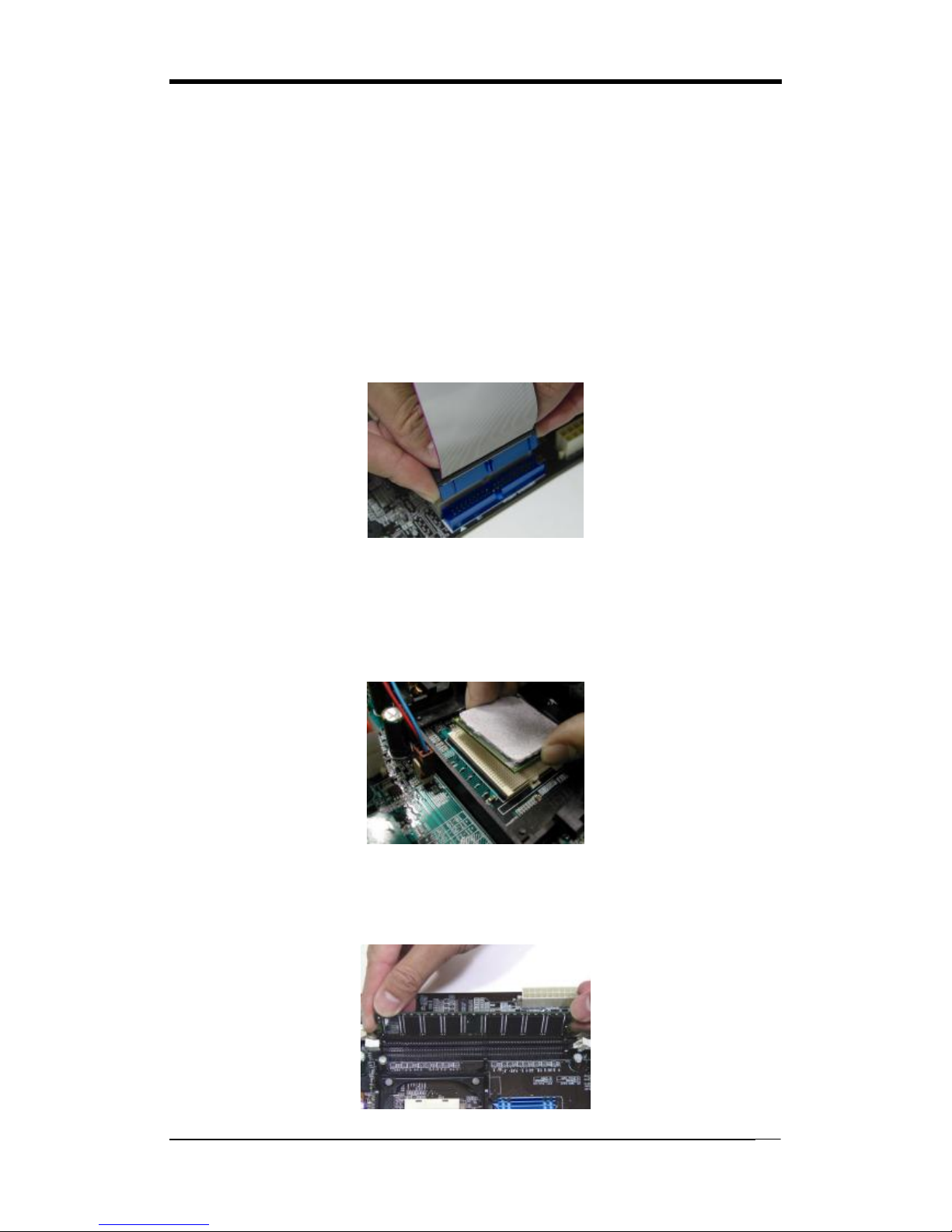
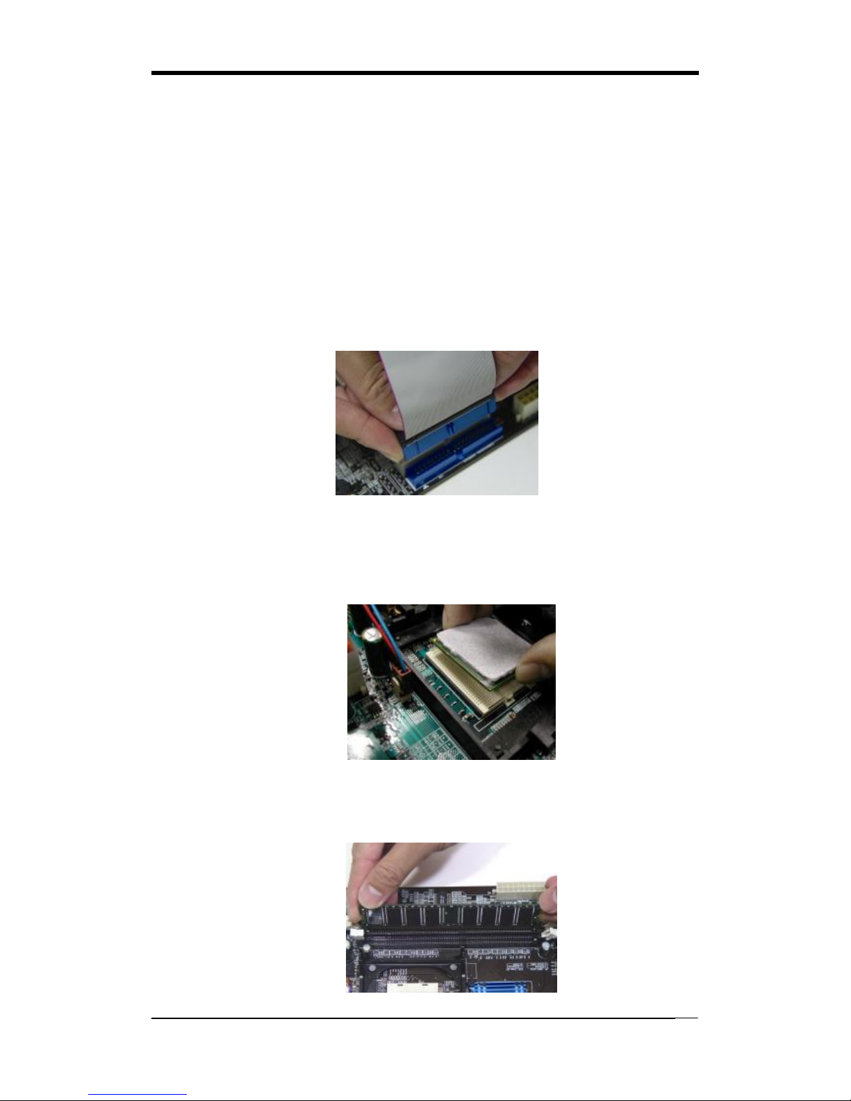
2. Installing FDD and IDE devices:
Aligned the red colored edge of the cable with the pin 1 of the drive connector on the
mainboard and gently attached it. Attach the other end of the cable by aligning the
colored edge to the pin 1 of the device connector. Make sure that all drives are
securely fastened.
3. Installing a CPU:
Locate a noticeable notch in the CPU’s corner. This marking indicate Pin 1 of the
CPU. Gently insert the CPU with Pin 1 at the same corner of the socket that contains
the end of the lever.
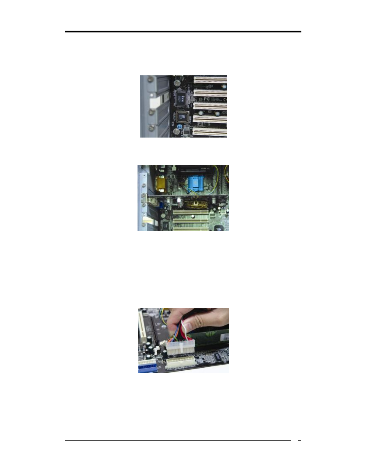
4. Installing System Memory:
Push module downward until side clips are properly secure to the module.
Chapter 2
5
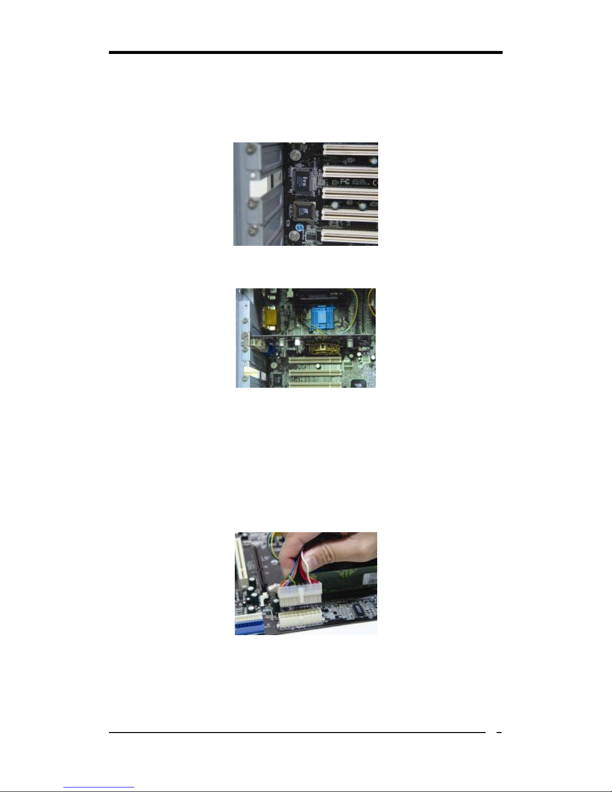
5. Mounting a Mainboard into a Chassis:
Use standoffs and screws to securely mount the mainboard and make sure that all the
mounting holes are properly screwed.
6. Adding an expansion card:
Gently fasten the card to the proper slot.
7. Connecting I/O ports and device connectors:
Simply plug the cable into the respective device port or connector as shown in the
manual or silkscreen printed on the mainboard.
8. Connecting the Power Supply Cables:
Plug in the ATX power cable to the mainboard’s power connector and make sure the
cable is connected.
Chapter 2
6
2-2 自行組裝電腦之作業指導重點 (Chinese)
1. 主機板硬體組態設定:
依據使用手冊上面的指令或印刷在主機板上的文字來設定 CPU 外頻,倍頻及電
壓或其它設定。
2. 安裝 FDD 和 IDE 裝置:
將排線較長一端的排線插入主機板 IDE 插槽並且紅色線對準插槽的第一針腳
(Pin 1),檢視排線接頭是否完全插入插槽,同時排線較短的一端也依序插入軟碟
機,硬碟機等儲存裝置。
3. 安裝 CPU:
將 CPU 的缺角對準 CPU 腳座的缺角並小心地將 CPU 插在腳座上,按下旁邊的
固定桿以固定 CPU。
4. 安裝系統記憶體:
先確定記憶體模組金手指的方向,慢慢插入記憶體插槽並小心地將記憶體模組往
下壓,直到插槽的固定卡榫卡住記憶體模組兩端的缺口。

Chapter 2
7
5. 主機板固定:
用銅柱及螺絲將主機板安裝在機殼底座並確定每個孔洞均已被鎖上,尤其注意主
機板底下不可有多餘的銅柱以避免造成短路。
6. 增加介面卡:
將介面卡(例 : 網路卡,音效卡等)插在適當的介面卡擴充插槽,並將卡上的鐵片
鎖緊在機殼上。
7. 連接 I/O 埠和其他設備的接頭:
適當地將排線插入各設備的插槽,記得必須將排線與插座的第一針腳互相對準,
請參照使用者手冊的主機板平面圖。
8. 連接電源供應器:
將電源接頭與主機板上之插座對準插入,並確定卡榫已緊扣。
Chapter 2
8
2-3 Français Instructions de montage du PC D.I.Y (French)
1. Positionnement des cavaliers (jumpers)
Positionnez les cavaliers de la fréquence d’horloge externe du microprocesseur, du
rapport de fréquence et de la tension d’alimentation du microprocesseur, suivant les
instructions qui figurent dans le manuel ou qui sont sérigraphiées sur la carte mère.
2. Installation du disque dur et des périphériques IDE
Alignez le côté coloré en rouge du câble avec la broche n°1 du connecteur de la carte
mère, et fixez le câble en douceur. Raccordez l’autre extrémité du câble en alignant le
côté coloré en rouge du câble avec la broche n°1 du connecteur du périphérique.
Vérifiez que tous les périphériques sont correctement fixés.
3. Installation d’un microprocesseur
Repérez l’encoche qui se trouve dans l’un des coins du microprocesseur. Cette
encoche indique la broche n°1 du microprocesseur. Insérez en douceur le
microprocesseur dans son support, en plaçant la broche n°1 du côté du support où se
trouve l’extrémité du levier de blocage.
4. Installation de la mémoire vive
Poussez la barrette dans son logement jusqu’à ce que les deux clips latéraux soient
correctement bloqués par le support module.
Chapter 2
9
5. Montage d’une carte mère dans son châssis
A l’aide des jauges d’espacement et des vis fournies, fixez fermement la carte mère
dans son emplacement, et vérifiez que tous les trous destinés à la fixation sont utilisés
et les vis sont correctement serrées.
6. Ajout d’une carte d’extension
Fixez avec précaution la carte dans le logement adapté.
7. Raccordement des ports d’E/S et des connecteurs des périphériques
Branchez simplement le câble dans le port ou le connecteur du périphérique concerné,
suivant les instructions qui figurent dans le manuel ou qui sont sérigraphiées sur la
carte mère.
8. Raccordement des câbles de l’alimentation électrique
Raccordez le câble d’alimentation ATX au connecteur d’alimentation de la carte mère,
et vérifiez qu’ils sont bien verrouillés en place.
Chapter 2
10
2-4 Deutsch PC D.I.Y.-Montageanleitung (German)
1. Steckbrücken Konfigureren
Die Anweisungen zum Einstellen des externen Prozessortakts, der Taktfrequenz
und der Prozesorspannung finden Sie im Hand buch oder direct auf dem
Motherboard.
2. Disketten- und Festplattenlaufwerke Installieren
Schließen Sie die rot markierte Kabelseite an Stift 1 des Laufweksanschlußes auf
dem Motherboard an. Bringen Sie das andere Kabelende am GeräteanSchluß.
Richten Sie dabei die rot markierte Kabelseite mit Stift 1 aus.
Überprüfen Sie den stabilen Sitz aller Laufwerke Kabel.
3. Prozessor Installieren
Der Prozessor ist an einer Stelle eingekerbt. Mit diesser Kerbe wird Stift 1 des
Prozessors gekennzeichnet. Setzen Sie den Prozessor vorsichtig in den Sockel ein,
und richten Sie dabei Stift 1 mit dem Hebelende aus.
4. Arbeitsspeicher einsetzen
Drücken Sie das Modul nach unten, bis die seitlichen Steckplatzhalterungernim
Modul eiratsen.

Chapter 2
11
5. Motherboard im Gehäuse montieren
Verwenden Sie das modul nach Schraubenund Abstandhalter, um das Motherboard stabil
im Gehäuse zu montieren. Achten Sie darauf, daß sämtliche Montagöffnungen korrekt
miet einer Schraube versekhen werden.
6. Steckkarte einbauen
Führen Sie die Karte vorsichtig in einen geeingneten Steckplatz ein.
7. Vo- und Geräteanschluße verbinden
Verbinden Sie das Kabel mit dem ensprechenden Geräteanschluß. Folgen Sie
dabei den Anweisungen im Handbuch oder direkt auf dem Motherboard.
8. Netzkabel anschließen
Verbinden Sie das ATX-Netzkabel korrekt mit dem Netzanschluß auf dem
Motherboard.
 Loading...