

ATX UCrypt Hardware Interface Manual

UCrypt
®
IP2 Av2
Patent Pending
UCrypt® Cable Gateways
HARDWARE INTERFACE MANUAL
www.atxnetworks.com
www.atxnetworks.com

General Guide Notes
Document ANW1216
Release Date May 22 2017
Organization of This Manual
This manual is generally organized based on the main interface tabs with individual chapters dedicated to describing the
con gurable features. Further chapters outline activities related to installation and the UI operation and con guration.
Cross Reference Usage
Hyperlinks are used throughout the guide to assist the reader in nding related information if the reader is viewing the PDF
le directly. Hyperlinks may be identi ed by their blue text. Most links are to related pages within the document, but some may
reference outside documents if the reader needs that additional information. The Table of Contents is entirely hyperlinked and
bookmarks are available but the bookmark feature must be turned on in your Reader application.
Symbol Usage
Throughout the manual, some symbols are used to call the readers attention to an important point. The following symbols are
in use:
WARNING: This symbol usage will call the reader’s attention to an important operation feature of
the equipment which may be safety related or may cause a service outage.
NOTE: This symbol indicates that there is helpful related information available in this note or
elsewhere in the guide.
Although every effort has been taken to ensure the accuracy of this document it may be necessary, without notice, to make amendments or correct omissions.
Speci cations subject to change without notice.
* Any use of the UCrypt® product, directly or indirectly, for the decryption and unauthorized reproduction of content that constitutes or may constitute copyright infringement or otherwise infringes on the
proprietary rights of any third party is expressly prohibited. No user of UCrypt shall use UCrypt for any purpose or in any manner which, directly or indirectly, violates the law, violates the proprietary rights of
any other party, or aids in any unlawful act or undertaking including, without limitation, laws governing data privacy, international data transmission, and export of technology or data. Any multiple systems
operator or other similar party (“MSO”) will use the UCrypt product in strict compliance with all applicable laws and in compliance with any agreement in effect between the MSO and a content provider.
In no event shall ATX Networks Corp. or any of its af liates be liable to an MSO, any end user of the UCrypt product, or any other third party, for any claims arising out of or related to any use or misuse
of the UCrypt product in contravention of this disclaimer. It is the express obligation of an MSO to convey this disclaimer to any other end user of the UCrypt product.
®
MDU Solutions
patents. Adobe® Flash® , and other non-ATX product and company names mentioned in this document are the property of their respective companies.
and UCrypt® are registered trademarks of ATX in the United States and/or other countries. Products or features contained herein may be covered by one or more U.S. or foreign

TABLE OF CONTENTS
GENERAL GUIDE NOTES ....................................................II
1. SAFETY ............................................................. 1-1
2. OVERVIEW ........................................................... 2-1
2.1 Chapter Contents ................................................. 2-1
2.2 Front Panels ..................................................... 2-1
2.3 Switch & Firewall Port Openings ..................................... 2-3
3. REAR PANELS ........................................................ 3-1
3.1 Chapter Contents ................................................. 3-1
3.2 UCrypt QAM to QAM .............................................. 3-1
3.3 UCrypt QAM to IP ................................................. 3-3
3.4 UCrypt QAM to Analog ............................................. 3-4
3.5 UCrypt IP to QAM ................................................. 3-5
3.6 UCrypt IP to IP ................................................... 3-6
4. INSTALLATION ........................................................ 4-1
4.1 Chapter Contents ................................................. 4-1
4.2 Preparation for Installation .......................................... 4-1
4.3 Precautions ...................................................... 4-1
4.4 General Mechanical ............................................... 4-2
4.5 General Electrical ................................................. 4-3
4.6 General Environment .............................................. 4-3
4.7 Gigabit Ethernet Ports ............................................. 4-3
4.8 Install the Device ................................................. 4-4
4.9 Equipment Safety Grounding ........................................ 4-5
4.10 AC Power Supplies ................................................ 4-5
4.11 DC Power Supplies ................................................ 4-6
4.12 Power Supply Redundancy ......................................... 4-7
5. INITIAL STARTUP ..................................................... 5-1
5.1 Connecting to the Management Computer .............................. 5-1
5.2 Factory Default IP Address .......................................... 5-1
5.3 Computer Requirements. . . . . . . . . . . . . . . . . . . . . . . . . . . . . . . . . . . . . . . . . . . . 5-1
5.4 Congure Your Computer ........................................... 5-2
5.5 Use a Browser to Login ............................................ 5-2
5.6 Reset Device to Factory ........................................... 5-3
6. SERVICE & SUPPORT .................................................. 6-1
6.1 Contact ATX Networks ............................................. 6-1
6.2 Warranty Information .............................................. 6-1
MDU Solutions® – UCrypt® - Hardware Interface Manual iii

This page intentionally left blank.
iv MDU Solutions® – UCrypt® - Hardware Interface Manual

SAFETY
1. Safety
WARNING! FAILURE TO FOLLOW THE SAFETY PRECAUTIONS LISTED BELOW MAY RESULT IN PROPERTY DAMAGE
OR PERSONAL INJURY. PLEASE READ AND COMPLY WITH THE FOLLOWING:
SAFETY GROUND: The connection to earth of the supplementary grounding conductor shall be in compliance with the
appropriate rules for terminating bonding jumpers in Part V of Article 250 of the National Electrical Code, ANSI/NFPA 70, and
Section 10 of Part I of the Canadian Electrical Code, Part I, CSA C22.1.
WATER AND MOISTURE: Care should be taken to prevent entry of splashed or dripping water, other liquids, and physical
objects through enclosure openings.
DAMAGE: Do not operate the device if damage to any components is suspected.
POWER SOURCES: Only connect the unit to a power supply of the type and capacity specied in the operating instructions
or as marked on the device.
NOTE: a) For 120 VAC operation, use the power cord supplied for operation from a 120 VAC source.
b) For 230 VAC operation, use the power cord supplied for operation from a 230 VAC source.
CHAPTER 1: SAFETY
GROUNDING OR POLARIZATION: Electrical grounding and polarization means must not be defeated.
POWER CORD PROTECTION: Care must be taken during installation to route or arrange the power supply cord to prevent
and avoid the possibility of damage to the cord by external objects. Pay particular attention to the exit point from the device
and plug.
POWER SUPPLY CORD ROUTING: The power supply cord shall not be attached to the building surface, nor run through
walls, ceilings, oors and similar openings in the building structure.
SERVICE: Do not attempt to service the device beyond procedures provided the operating instructions. All other servicing
should be referred to qualied service personnel.
MODIFICATIONS: Modications should not be made to the device or any of its components for applications other than those
specied in the operating instructions.
SAFETY CODES AND REGULATIONS: The device should be installed and operated in compliance with all applicable local
safety by-laws, codes and regulations.
REDUNDANT POWER SUPPLY REMOVAL: Power must be disconnected from the BOTH power modules before removing
for replacement or service. This is accomplished by removing both of the AC IEC plugs or operating the DC power disconnects.
BATTERY REMOVAL AND REPLACEMENT: Disconnect power (AC or DC) from the equipment before battery removal and
replacement. This is accomplished by unplugging the power cord from the power outlet. Replace the battery with Sony part
No. CR2032 or exact replacement only.
CAUTION: Use of a different battery type may present a risk of re or explosion.
BATTERY DISPOSAL: Recycle or dispose of batteries in accordance with the battery manufacturer’s instructions and local/
national disposal and recycling regulations. Please call 1-800-8-BATTERY or go to the website at www.call2recycle.org for
information on recycling or disposing of your used battery.
MDU Solutions® – UCrypt® - Hardware Interface Manual 1-1

CHAPTER 1: SAFETY
This page intentionally left blank.
1-2 MDU Solutions® – UCrypt® - Hardware Interface Manual

OVERVIEW
2. Overview
This installation manual covers all hardware and initial installation aspects of the following UCrypt models:
• QAM to QAM
• QAM to IP
• QAM to Analog
• IP to QAM
• IP to IP
The Rear Panels chapter, see “Rear Panels” on page 3-1, shows each individual model and their connection arrangements.
2.1 Chapter Contents
• “Front Panels”
• “Switch & Firewall Port Openings”
CHAPTER 2: OVERVIEW
2.2 Front Panels
The front panels are common to Devices of the same Hardware Version. Version 3 Devices contain a set of controls and
indicators to show the status of important operation parameters and allow some control over the device.
2.2.1 Version 3 Front
The Version 3 UCrypt models have an integral control panel allowing some power functions and diagnostics as described in
Table 2.2a. The products are designed to be plug and play and will be in a powered on state when the power cord is plugged
in. There may be instances where it is desired to reboot or power down the devices manually and recessed switches to enable
that are located on the front panel, a closeup view of which is shown in Figure 2-1. See Table 2.2a for functional descriptions
of all front panel controls and indicators.
Table 2.2a: Front Panel Controls and Indicators (See Figure 2-1)
Label Function Description
PWR Recessed Button Power Switch. This is the main power switch and is used to apply or remove power to the Device. Activating
RST Recessed Button Reset Switch. Used to warm reboot the Device. Functionally equal to a reset button on a computer.
PWR Indicator LED
Green
HDD Indicator LED
Green
ETH0 Indicator LED
Green
ETH1 Indicator LED
Green
Controls Closeup
Figure 2-1: Version 3 Front
this switch effectively turns the Device off but keeps standby power supplied to the system. You must unplug
the system before servicing. Press again to power up. Functionally equal to a power button on a computer.
Indicates power is being supplied to the system’s power supply units. This LED should be illuminated when
the system is operating.
Indicates SSD/HDD drive activity when ashing.
Indicates network activity on ETH0 network port. On the rear panel, this refers to the labeled port eth1.
Indicates network activity on ETH1 network port. On the rear panel, this refers to the labeled port eth2.
MDU Solutions® – UCrypt® - Hardware Interface Manual 2-1
CHAPTER 2: OVERVIEW
Label Function Description
U Indicator LED
Blue
UID Recessed Button Universal Identi er: A switch that will turn on the adjacent “U” light.
2.2.2 Version 2 Front
Universal Information LED: The Universal Information BLUE LED is used to indicate fan failure, power failure,
overheat condition, or to identify the unit within a large rack installation. This may be activated by the front
panel button.
State Indication:
• Fast Blinking Red (1 per sec) - Fan Failure
• Solid Red - CPU Overheated
• Slow Blinking Red (1 per 4 sec) - Power Failure
• Solid Blue - Local UID Button Depressed
• Blinking Blue - IPMI Activated UID
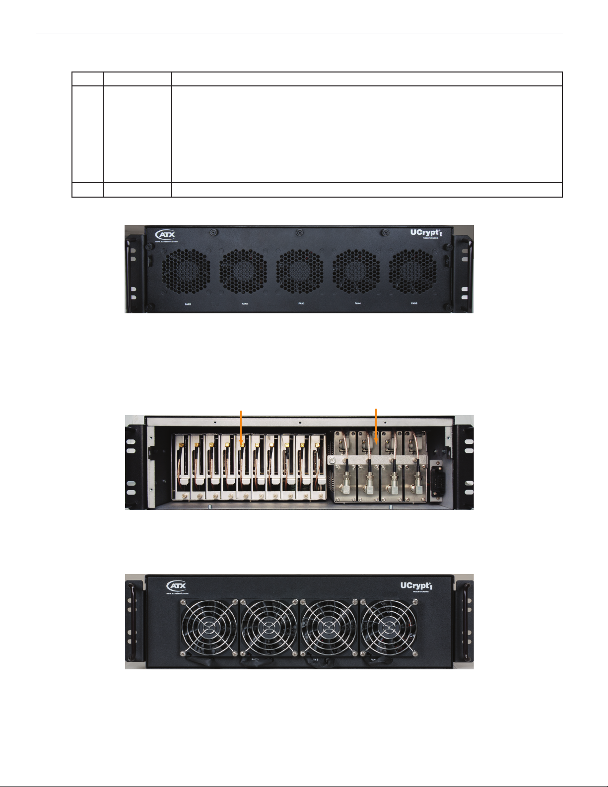
2.2.3 Version 2 Front Inside
Figure 2-3 shows the interface modules behind the QAM to QAM Version 2 front panel. The QAM to IP will have just the
CableCARD modules, the IP to QAM will have just the DQAM modules while the IP to IP will not have any modules behind
the front panel.
2.2.4 Version 1.7 & 1.8 Front
Figure 2-2: Version 2 Front
Tuner & CableCARD™ Modules DQAM Modules
Figure 2-3: Version 2 QAM to QAM Front Inside
Figure 2-4: Version 1.7 & 1.8 Front
2-2 MDU Solutions® – UCrypt® - Hardware Interface Manual
2.3 Switch & Firewall Port Openings
Any Management Switch used between UCrypt Devices and the Management Computer will require the following ports to be
opened both Inbound and Outbound.
NOTE: Failure to open these ports may result in communications problems between the
management computer and UCrypt Devices.
Table 2.3a: Ports to Open on Switch
Port Number Transport Protocol
80 TCP HTTP
443 TCP HTTPS
CHAPTER 2: OVERVIEW
•
MDU Solutions® – UCrypt® - Hardware Interface Manual 2-3

CHAPTER 2: OVERVIEW
This page intentionally left blank.
2-4 MDU Solutions® – UCrypt® - Hardware Interface Manual
 Loading...