

ATX TranScend Operation Manual

TranScend
TranScend Chassis
OPERATION MANUAL
www.atxnetworks.com
www.atxnetworks.com

Although every effort has been taken to ensure the accuracy of this document it may be necessary, without notice, to make amendments or correct omissions.
Specications subject to change without notice.
Products or features contained herein may be covered by one or more U.S. or foreign patents. Other non-ATX product and company names in this manual are the property of their respective
companies.

TABLE OF CONTENTS
1. SCOPE ................................................................ 1-1
2. LED DISPLAY .......................................................... 2-1
2.1. LED Color Codes ................................................... 2-1
2.1.1 High Sensitivity Quad Return Receiver ................................. 2-2
2.1.2 PON EDFA ....................................................... 2-2
2.1.3 Quad Return Receiver .............................................. 2-2
2.1.4 Destacker ........................................................ 2-2
2.1.5 Stacker .......................................................... 2-3
2.1.6 Optical Switch ..................................................... 2-3
2.1.7 Forward Receiver .................................................. 2-3
2.1.8 RF Switch ........................................................ 2-3
2.1.9 AGC EDFA ....................................................... 2-3
2.1.10 Transceiver ...................................................... 2-4
2.1.11 High Sensitivity Opto-Stacker ........................................ 2-4
2.1.12 Direct Forward Transmitter (DFB Tx) .................................. 2-4
2.1.13 Opto-Stacker .................................................... 2-5
3. PUSHBUTTON OPERATIONS ............................................. 3-1
3.1 Philosophy of Button Operations ........................................ 3-1
3.1.1 Individual Button Operations ......................................... 3-1
3.1.2 Combination Button Operations ....................................... 3-2
4. FRONT PANEL LCD DISPLAY ............................................. 4-1
4.1 Menu Tree Structure ................................................. 4-1
4.2 System Menu Trees. . . . . . . . . . . . . . . . . . . . . . . . . . . . . . . . . . . . . . . . . . . . . . . . . . 4-1
4.3 Plug-in Menu Tree ................................................... 4-2
4.3.1 High Sensitivity Quad Return Receiver ................................. 4-2
4.3.2 PON EDFA ....................................................... 4-4
4.3.3 Quad Return Receiver .............................................. 4-6
4.3.4 Destacker Proxy ................................................... 4-8
4.3.5 I-HUB Proxy ..................................................... 4-10
4.3.6 Stacker ..........................................................4-11
4.3.7 Optical Switch .................................................... 4-13
4.3.7.1 Optical Switch Switching Criteria .................................... 4-14
4.3.8 Forward Receiver ................................................. 4-14
4.3.9 RF Switch ....................................................... 4-16
4.3.9.1 RF Switch Switching Criteria ....................................... 4-17
4.3.10 AGC-EDFA ..................................................... 4-17
4.3.11 Transceiver ..................................................... 4-20
4.3.12 High Sensitivity Opto-Stacker ....................................... 4-23
4.3.13 Direct Forward Transmitter (DFB Tx) ................................. 4-25
4.3.14 Opto-Stacker ................................................... 4-27
5. CRAFT LINE INTERFACE (CLI) ............................................ 5-1
5.1 Command Structure ................................................. 5-1
5.1.1 System Commands ................................................ 5-1
TranScend Chassis – Operation Manual iii

5.1.2 Plug-in Commands ................................................. 5-6
5.1.2.1 Common Commands. . . . . . . . . . . . . . . . . . . . . . . . . . . . . . . . . . . . . . . . . . . . . . 5-6
5.1.2.2 High Sensitivity Quad Return Receiver ................................ 5-6
5.1.2.3 PON EDFA. . . . . . . . . . . . . . . . . . . . . . . . . . . . . . . . . . . . . . . . . . . . . . . . . . . . . . 5-7
5.1.2.4 Quad Return Receiver ............................................. 5-8
5.1.2.5 Destacker Proxy ................................................. 5-9
5.1.2.6 Stacker ....................................................... 5-10
5.1.2.7 Optical Switch ...................................................5-11
5.1.2.8 Forward Receiver ............................................... 5-12
5.1.2.9 RF Switch ..................................................... 5-14
5.1.2.10 AGC EDFA .................................................... 5-16
5.1.2.11 Transceiver ................................................... 5-17
5.1.2.12 High Sensitivity Opto-Stacker ..................................... 5-19
5.1.2.13 Direct Forward Transmitter (DFB Tx) ............................... 5-22
5.1.2.14 Opto-Stacker .................................................. 5-24
6. GRAPHICAL USER INTERFACE ........................................... 6-1
6.1 System Login Page .................................................. 6-1
6.2 Home Page ........................................................ 6-1
6.3 Chassis Status Page ................................................. 6-1
6.4 Chassis Alarm Page ................................................. 6-2
6.4.1 Top Page ........................................................ 6-3
6.4.2 Bottom Page ...................................................... 6-3
6.5 System Command Page .............................................. 6-4
6.5.1 Conguration Example .............................................. 6-4
6.5.2 Readback Example ................................................ 6-5
7. USER INTERFACE CROSS REFERENCE .................................... 7-1
7.1 System / Chassis Attributes ............................................ 7-1
7.2 High Sensitivity Quad Return Receiver Attributes ........................... 7-1
7.3 PON EDFA Attributes. . . . . . . . . . . . . . . . . . . . . . . . . . . . . . . . . . . . . . . . . . . . . . . . . 7-1
7.4 Quad Return Receiver Attributes ........................................ 7-2
7.5 Destacker Attributes ................................................. 7-2
7.6 Stacker Attributes ................................................... 7-2
7.7 Optical Switch Attributes .............................................. 7-3
7.8 Forward Receiver Attributes ........................................... 7-3
7.9 RF Switch Attributes ................................................. 7-3
7.10 AGC EDFA Attributes ................................................ 7-4
7.11 Transceiver Attributes ............................................... 7-4
7.12 High Sensitivity Opto-Stacker ......................................... 7-5
7.13 Direct Forward Transmitter (DFB Tx) Attributes ........................... 7-5
7.14 Opto-Stacker Attributes .............................................. 7-6
8. SNMP ENTERPRISE ATTRIBUTES ......................................... 8-1
9. SERVICE & SUPPORT .................................................. 9-1
9.1 Contact ATX Networks ............................................. 9-1
9.2 Warranty Information .............................................. 9-1
iv TranScend Chassis – Operation Manual

SCOPE
1. Scope
This document describes the user interfaces for TranScend family chassis. The user interfaces include front panel LED,
buttons operations, LCD display, Craft Line Interfaces and remote monitoring through SNMP.
CHAPTER 1:
NOTE: An overcurrent protection device for permanent connection must be included at the site as
a building installation requirement.
SCOPE
TranScend Chassis – Operation Manual 1-1

CHAPTER 1:
SCOPE
This page intentionally left blank.
1-2 TranScend Chassis – Operation Manual

LED DISPLAY
2. LED Display
There are nine front panel LEDs, one indicates the chassis power supply status and four sets of two each indicate the status
of the four plug-in units. The number labeled on the front panel correspond to the slot identication; one on the most left and
four on the most right (closest to power switch) when facing the rear of the chassis. Figure 1 below shows the generic alarm
table and corresponding color codes.
2.1 LED Color Codes
There are four possible colors of LEDs. They are observed during the following conditions.
Off: indicates the monitored function is unavailable. This is also observed temporarily during power on LED test.
Example #1: Only slot 1 and slot 2 have plug in units. The LEDs for slot 3 and slot 4 are off.
Example #2: The High Sensitivity Quad Return Receiver is detected in slot 1; the RF LED for slot 1 is turned off
since RF detection is not available in this unit.
CHAPTER 2:
LED DISPLAY
Green: indicates the monitored function is healthy. This is also temporarily observed during power on LED test.
Example #1: The High Sensitivity Quad Return Receiver is detected in slot 1, and the OPT LED for slot 1 is green
which indicates the monitored level of all four optical power receivers in slot 1 are within normal operating range.
Amber: indicates the monitored function is in minor alarm condition. This is also temporarily observed during power on LED
test.
Example #1: The High Sensitivity Quad Return Receiver is detected in slot 1, and the OPT LED for slot 1 is amber
which indicates the level of any one or more of the four optical power receivers in slot 1 are in minor alarm range.
The minor alarm is triggered if the monitored level is between the high and high-high or low and low-low thresholds.
Red: indicates the monitored function is in major alarm condition. This is also observed temporarily during power on LED
test.
Example #1:The High Sensitivity Quad Return Receiver is detected in slot 1, and the OPT LED for slot 1 is red
which indicates the level of any of the four optical power receivers in slot 1 are within major alarm range. The major
alarm is triggered if the monitored level is beyond the high-high or low-low thresholds.
Major/High-High
Minor/High
Red
Amber
Nominal
Minor/Low
Green
Amber
RedMajor/Low-Low
Figure 1: Generic Alarm & LED Table Plug-in LED Denitions
TranScend Chassis – Operation Manual 2-1

LED DISPLAY
CHAPTER 2:
2.1.1 High Sensitivity Quad Return Receiver
The High Sensitivity Quad Return Receiver detects the alarms and reects them on the front panel LEDs based on the
following schema.
LED Location Trigger Events
Top Optical receive power
Module temperature
Bottom Disable
Example #1: The module temperature and optical receive power on channel #1, #2 are normal and the channel #3
is minor low, but the channel #4 is major low low. The top LED associated with the slot shall be observed as “red”,
since this is the worst case scenario for any of the observed parameters. The top LED may show green regardless
of the real-time alarm status if the per channel alarm enable switch is set as “OFF”.
2.1.2 PON EDFA
The PON EDFA detects the alarms and reects them on the front panel LEDs based on the following schema.
LED Location Trigger Events
Top Optical input power
Optical output power
Module temperature
Bottom Disable
Example #1: The module temperature and optical output power is normal, but the optical input power is at a level
that indicates a major alarm. The top LED associated with the slot shall be observed as “red”.
2.1.3 Quad Return Receiver
The Quad Return Receiver detects the alarms and reects them on the front panel LEDs based on the following schema.
LED Location Trigger Events
Top Optical receive power
Module temperature
Bottom Software version 2.6 and before - green
Software version 2.7 and later- disable
Example #1: The module temperature is normal, but optical receive power is major low low. The top LED
associated with the slot shall be observed as “red”.
2.1.4 Destacker
The Destacker detects the alarms and reects them on the front panel LEDs based on the following schema.
LED Location Trigger Events
Top Optical power
Module temperature
Bottom Synthesizer lock state
Example #1: The module temperature is normal, but optical power is major low low. The top LED associated with
the slot shall be observed as “red”.
2-2 TranScend Chassis – Operation Manual

2.1.5 Stacker
The Stacker detects the alarms and re ects them on the front panel LEDs based on the following schema.
LED Location Trigger Events
Top Optical power
Bottom Synthesizer lock state
Example #1: The module temperature is normal, but optical power is major low low. The top LED associated with
the slot shall be observed as “red”.
2.1.6 Optical Switch
The Optical Switch detects the alarms and re ects them on the front panel LEDs based on the following schema.
LED Location Trigger Events
Top Primary and secondary optical input power
Bottom Disable
Module temperature
Switch alarm
Module temperature
CHAPTER 2:
LED DISPLAY
Example #1: The module temperature is normal, but primary optical power is major low low. The top LED
associated with the slot shall be observed as “red”.
2.1.7 Forward Receiver
The Forward Receicer detects the alarms and re ects them on the front panel LEDs based on the following schema.
LED Location Trigger Events
Top Optical power
Bottom Disable
Example #1: The module temperature is normal, but optical power is major low low. The top LED associated with
the slot shall be observed as “red”.
2.1.8 RF Switch
The Optical Switch detects the alarms and re ects them on the front panel LEDs based on the following schema.
LED Location Trigger Events
Top Switch alarm
Bottom Primary and secondary RF input
Module temperature
Module temperature
Example #1: The module temperature is normal, but primary optical power is major low low. The top LED
associated with the slot shall be observed as “red”.
2.1.9 AGC EDFA
NOTE: The AGC EDFA described in this document applies to the rmware release 1.21 or later.
TranScend Chassis – Operation Manual 2-3

LED DISPLAY
CHAPTER 2:
The AGC EDFA detects the alarms and reects them on the front panel LEDs based on the following schema.
LED Location Trigger Events
Top Optical input power
Bottom Disable
Example #1: The optical input power is at a level that indicates a major alarm, but the rest of the attributes are
normal. The top LED associated with the slot shall be observed as “red”.
2.1.10 Transceiver
The Transceiver (also known as MDU) detects the alarms and reects them on the front panel LEDs based on the following
schema.
LED Location Trigger Events
Top Laser Temperature
Bottom RF
Optical output power
Gain
Module temperature
Laser Power
Optical Input Power
Module temperature
Example #1: The optical input power is at a level that indicates a major alarm, but the rest of the attributes are
normal. The top LED associated with the slot shall be observed as “red”.
2.1.11 High Sensitivity Opto-Stacker
The High Sensitivity Opto-stacker is a dual wide plug-in that detects the alarms and reects them on the front panel LEDs
based on the following schema.
LED Location Trigger Events
Top Laser Temperature
Optical Input and output Power
Module temperature
Bottom Lock
Example #1: The optical input power is at a level that indicates a major alarm, but the rest of the attributes are
normal. The top LED associated with the slot shall be observed as “red”.
2.1.12 Direct Forward Transmitter (DFB Tx)
The Direct Forward Transmitter detects the alarms and reects them on the front panel LEDs based on the following
schema.
LED Location Trigger Events
Top Laser Temperature
Optical Input Power
Module temperature
Bottom RF
Example #1: The optical input power is at a level that indicates a major alarm, but the rest of the attributes are
normal. The top LED associated with the slot shall be observed as “red”.
2-4 TranScend Chassis – Operation Manual

2.1.13 Opto-Stacker
The Opto-stacker is a dual wide plug-in that detects the alarms and reects them on the front panel LEDs based on the
following schema.
LED Location Trigger Events
Top Laser Temperature
Bottom Lock
Example #1: The optical input power is at a level that indicates a major alarm, but the rest of the attributes are
normal. The top LED associated with the slot shall be observed as “red”.
Optical Input and output Power
Module temperature
CHAPTER 2:
LED DISPLAY
TranScend Chassis – Operation Manual 2-5

LED DISPLAY
CHAPTER 2:
This page intentionally left blank.
2-6 TranScend Chassis – Operation Manual
PUSHBUTTON OPERATIONS
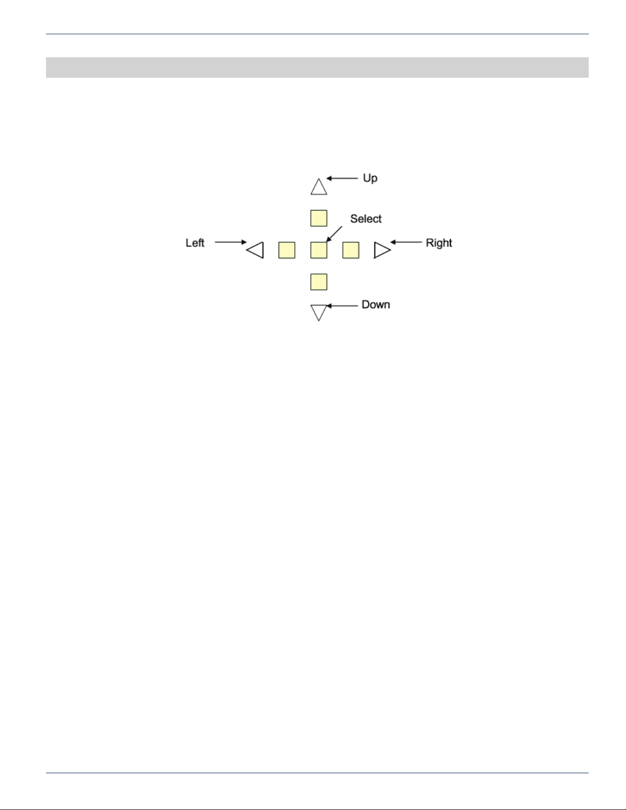
3. Pushbutton Operations
There are ve pushbuttons located at the front panel of chassis. They are designated as “Up” with a upper arrow indicator,
“Right” with a right arrow indicator, “Left” with a left arrow indicator, “Down” with a down arrow indicator and “Select” as the
center button.
CHAPTER 3:
PUSHBUTTON OPERATIONS
3.1 Philosophy of Button Operations
3.1.1 Individual Button Operations
Up: The cursor moves up one line
Down: The cursor moves down one line
Right: Cycle through the available options for the line where cursor is located.
If the menu is for read-only attribute, the display shows the next available interface.
Example #1: If the current display is “#1 Optical Power”, the “#2 Optical Power” shall be displayed after “Right”
button is pressed.
Example #2: If the menu is for the quantitative write attributes, the “Right” button increases the value.
In the “Gain Setting Menu”, the cursor displays Gain (steps): 1, the Gain (steps): 2 shall be displayed after the
“Right” button is pressed once.
Left: Cycle through the available options for the line where cursor is located
If the menu is for read-only attribute, the display shows the next available interface.
Example #1: If the current display is “#2 Optical Power”, the “#1 Optical Power” shall be displayed after “Left”
button is pressed.
Example #2: If the menu is for the quantitative write attributes, the left button decreases the value.
In the “Gain Setting Menu”, the cursor displays Gain (steps): 3, the Gain (steps): 2 shall be displayed after “Left”
button is pressed.
Select: There are multiple meanings to the select button.
• Select to execute the action where the cursor is located.
Example #1: If the cursor is located at the “Prev menu” line, the display shall change to the NEXT higher
menu after the “Select” button is pressed once.
• Select to commit the option.
Example #1: In the “Gain Setting Menu”, if the cursor is located on the “Sel Ch: 1” line, the channel #1
shall be used for gain adjustment after “Select” button is pressed.
TranScend Chassis – Operation Manual 3-1

CHAPTER 3:
PUSHBUTTON OPERATIONS
NOTE: Only after pressing the Select button, the gain settings option is operated on the selected
channel.
• Select to commit the setting to NVRAM
Example #1: In the “Gain Setting Menu”, if cursor is on “Save: No (17)”, user must toggle the right or left
button to change the option to “Yes”. Then press “Select” to commit the value, 17, in the bracket into the
NVRAM.
NOTE: Only if the value is committed into NVRAM, the chassis will use the selected gain level next
time the chassis recovers from power cycle.
3.1.2 Combination Button Operations
The combination button operations are unique to TranScend chassis. Each combination operation is de ned strictly for their
speci c usage as the following de nition.
UP+DOWN: When pressing and holding the UP+DOWN button simultaneously when traversing the slot menu, the front
panel displays current slot number. The front panel display will restore back to the previous display once the button
combination is released.
Example #1: User is within the “Status Menu” of slot #1, press and hold the Up and Down buttons, the front panel
displays “Current Slot: 1”. The “Status Menu” returns after releasing the Up and Down button combinations.
LEFT+RIGHT: When pressing and holding the LEFT+RIGHT button simultaneously, the front panel displays tree’s top menu
of sub-tree. The top menu is usually the module’s Greetings.
NOTE: The support of this feature starts on plugin software version 2.1D or later.
3-2 TranScend Chassis – Operation Manual

FRONT PANEL LCD DISPLAY
4. Front Panel LCD Display
4.1 Menu Tree Structure
The TranScend chassis LCD menu is structured into bi-level trees. The top level is system related information and the
second level is plug-in related information. The top level contains the menu for second level, but each has its own menu
structure.
Level 1 Level 2 Level 3
Greeting Slot
Chassis Model
CHAPTER 4:
Hardware Version
Software Version
Serial Number
FRONT PANEL LCD DISPLAY
4.2 System Menu Trees
TranScend chassis displays the greeting message upon chassis power up.
Greeting:
InnoTrans Communications
Transcend
Press “Select” button to go into the system menus. The entries in system menus are described as follows:
Slot:
This displays the detected plug-in card type or “Empty” if none is detected. Press “Right” or “Left” button to cycle through
available slots. Press “Select” to show the slot status. If the communication with slot establishes successfully, the display will
go into the second level plug-in menu. Keep in mind that the slot numbering scheme is 1, 2, 3, 4 going from the LEFT when
you are facing the rear of the chassis.
Prev Menu
Alarm Power Supply
Fan
Prev Menu
Prev Menu
Table 1: TranScend Front Panel System Menu Overview
Slot Status:
Module Greeting: Communication is established with plug-in.
Empty: No module is detected in the slot.
Failed to Switch: Cannot establish communication with module.
TranScend Chassis – Operation Manual 4-1

CHAPTER 4:
FRONT PANEL LCD DISPLAY
Multi-slot unit; Display avail on slot #: this is the virtual slot on a multiple slot unit. User can access the module’s display
menu via the lowest slot of the multi slot unit. The slot # is shown.
Chassis:
Displays all system related information.
Model: Displays the chassis’ model name.
HW Ver: Displays the hardware version information of TranScend chassis.
SW Ver: Displays the software version information of TranScend chassis.
Ser #: Displays the serial number of TranScend chassis.
Alarm:
Display all system related alarm status.
Pwr Sply: displays the health of chassis power supply.
Fan: displays the collective health of the chassis fans.
Prev Menu:
Press “Select” will bring the Greeting Message screen back.
NOTE: “Prev Menu” exists in all menu trees AT THE VERY BOTTOM. When you see it, place the
cursor on this line and press the “Select” button will go back to the previous menu.
4.3 Plug-in Menu Tree
The plug-in menu displays is driven by the card type. Each model provides its own display structure. In any sub menu, press
“Select” on the Prev Menu line to return to the previous menu one level up.
4.3.1 High Sensitivity Quad Return Receiver
Level 1 Level 2 Level 3 Level 4
Greeting Setup Attn Setting Select Channel
Test Point Select Channel
Alarm Enable Channel
Prev Menu
Status Optical
Attn (dB)
Save
Prev Menu
Prev Menu
Enable
Save
Prev Menu
Prev Menu
Alarm Receiver Power
Module Temp
Prev Menu
4-2 TranScend Chassis – Operation Manual

Prev Menu
Table 2: TranScend High Sensitivity Quad Return Receiver Front Panel Display Menu Overview
Greeting:
Greeting Message
InnoTrans Communications
HS Quad Return Rcvr
Optical Power (dBm)
Attn (dB)
Prev Menu
Chassis Temperature(C)
Model
Hardware Version
Software Version
Serial Number
Prev Menu
Prev Menu
CHAPTER 4:
FRONT PANEL LCD DISPLAY
Press “Select” button to go into the plug-in menu.
Prev Menu:
Press “Select” will bring back to the System menu.
The entries in plug-in menu are described as follows:
Setup Menu:
Attn Setting Menu:
Sel Ch: Press “Select” to select the channel for attenuation adjustment. Press “Right” or “Left” button to cycle
through available channels.
Attn (dB): Press “Select” to set the attenuation level. Press “Right” to increase or “Left” button to decrease the
attenuation level.
NOTE: After the attenuation level adjustment, user must press “Select” to commit the attenuation
level in order for the plug-in to operate at such level and for NVRAM storage. Fail to do so, the
attenuation might revert back to previous level.
Save: Press “Right” or “Left” button to select between “Yes” or “No”. Press “Select” to commit the value into
NVRAM when “Yes” is selected. The value in bracket re ects the current NVRAM contents. If user presses “Select”
when display is “No”, no NVRAM change takes place.
Test Point Menu: Select the test point connection to front panel “RF TEST” output.
Sel Ch: Press “Select” to select the channel to connect to the front panel “RF TEST” output. Press “Right” or “Left”
button to cycle through available channels.
Alarm Enable Menu: Enable or disable alarms on the selected channel. Note: the alarm’s enable or disable switch
only applies to the analog attributes on per channel basis. These attributes include Optical Power Level, RF and
Laser Temperature.
TranScend Chassis – Operation Manual 4-3

CHAPTER 4:
FRONT PANEL LCD DISPLAY
Channel: Press “Right” or “Left” button to cycle through available channels.
Enable: Press “Select” to enable or disable the alarm reporting. Press “Right” or “Left” button to cycle
through the available options.
On: Report alarms on the selected channel
Off: Disable alarm reporting on the selected channel
Save: Press “Right” or “Left” button to select between “Yes” or “No”. Press “Select” to commit the value
into NVRAM when “Yes” is selected. The value in bracket reects the current NVRAM contents. If user
presses “Select” when display is “No”, no NVRAM change takes place.
Status Menu:
Opt: Displays the reading of optical receiver power in dBm. This display does not include the reading after the
decimal point.
Alarm Menu:
Rcvr Pwr: Displays the alarm status of optical receiver power.
Module Temp: Displays the alarm status of module temperature.
Optical Menu:
Power (dBm): Displays the optical receiver power reading in dBm.
Attn (dB): Displays the attenuation setting in dB on per channel basis.
Chassis Menu:
Temp(C): Displays the module’s temperature reading in Centigrade.
Model: Displays the model name of plug-in module.
HW Ver: Displays the hardware version information of plug-in module.
SW Ver: Displays the software version information of plug-in module.
Ser #: Displays the serial number of plug-in module.
Prev Menu:
Press “Select” will bring the plug-in’s greeting message screen back.
4.3.2 PON EDFA
Level 1 Level 2 Level 3 Level 4
Greeting Status Laser Temperature (C)
Bias (mA)
Optical Input (dBm)
Optical Output (dBm)
Prev Menu
Alarm Laser Temperature
Optical Input
Optical Output
Module Temperature
Shutoff
Prev Menu
4-4 TranScend Chassis – Operation Manual

Chassis Temperature(C)
Model
Hardware Version
Software Version
Serial Number
Prev Menu
Prev Menu
Prev Menu
Table 3: TranScend Pon EDFA Front Panel Display Menu Overview
Greeting:
Greeting Message
InnoTrans Communications
PON EDFA
Press “Select” button to go into the plug-in menu.
CHAPTER 4:
FRONT PANEL LCD DISPLAY
Prev Menu:
Press “Select” will bring back to the System menu.
The entries in plug-in menu are described as follows:
Status Menu:
Laser Temp(C): Displays the reading of laser temperature in Centigrade. Press “Left” or “Right” button to cycle
through the available channels.
Bias (mA): Displays the reading of the laser bias in mA. Press “Left” or “Right” button to cycle through the available
channels.
OPT Input (dBm): Displays the reading of optical input power in dBm.
OPT Output (dBm): Displays the reading of optical output power in dBm.
Alarm Menu:
Laser Temp: Displays the alarm status of laser temperature. Press “Right” or “Left” button to cycle through
available channels.
OPT Input: Displays the alarm status of the optical input power.
OPT Output: Displays the alarm status of the optical output power.
Module Temp: Displays the alarm status of module temperature.
Shutoff: Displays the alarm status of pump shutoff.
Chassis Menu:
Temp(C): Displays the module’s temperature reading in Centigrade.
Model: Displays the model name of plug-in module.
HW Ver: Displays the hardware version information of plug-in module.
SW Ver: Displays the software version information of plug-in module.
Ser #: Displays the serial number of plug-in module.
Prev Menu:
Press “Select” will bring the plug-in’s greeting message screen back.
TranScend Chassis – Operation Manual 4-5

CHAPTER 4:
FRONT PANEL LCD DISPLAY
4.3.3 Quad Return Receiver
Level 1 Level 2 Level 3 Level 4
Greeting Setup Attn Setting Select Channel
Status Optical
Attn (dB)
Save
Prev Menu
Test Point Select Channel
Prev Menu
Alarm Enable Channel
Enable
Save
Prev Menu
Prev Menu
Prev Menu
Prev Menu
Alarm Receiver Power
Module Temp
Prev Menu
Optical Power (dBm)
Attn (dB)
Prev Menu
Chassis Temperature(C)
Model
Hardware Version
Software Version
Serial Number
Prev Menu
Prev Menu
Table 4: TranScend Quad Return Receiver Front Panel Display Menu Overview
Greeting:
Greeting Message
InnoTrans Communications
Quad Return Rcvr
Press “Select” button to go into the plug-in menu.
Prev Menu:
Press “Select” will bring back to the System menu.
4-6 TranScend Chassis – Operation Manual

CHAPTER 4:
FRONT PANEL LCD DISPLAY
The entries in plug-in menu are described as follows:
Setup Menu:
Attn Setting Menu:
Sel Ch: Press “Select” to select the channel for attenuation adjustment. Press “Right” or “Left” button to
cycle through available channels.
Attn (dB): Press “Select” to set the attenuation level. Press “Right” to increase or “Left” button to
decrease the attenuation level.
NOTE: After the attenuation level adjustment, user must press “Select” to commit the attenuation
level in order for the plug-in to operate at such level and for NVRAM storage. Fail to do so, the
attenuation will revert back to previous level after the module recovers from power cycle.
Save: Press “Right” or “Left” to select between “Yes” or “No”. Press “Select” to commit the value into
NVRAM when “Yes” is selected. The value in bracket re ects the current NVRAM contents. If user
presses “Select” when display is “No”, no NVRAM change takes place.
Test Point Menu: Select the test point connection to front panel “RF TEST” output.
Sel Ch: Press “Select” to select the channel to connect to the front panel “RF TEST” output. Press “Right” or “Left”
button to cycle through available channels.
Alarm Enable Menu: Enable or disable alarms on the selected channel. Note: the alarm enable or disable switch only
applies to the analog attributes on per channel bassis. These attributes include Optical Power Level, RF and Laser
Temperature.
Channel: Press “Right” or “Left” button to cycle through available channels.
Enable: Press “Select” to enable or disable the alarm reporting. Press “Right” or “Left” button to cycle through the
available options.
On: Report alarms on the selected channel
Off: Disable alarm reporting on the selected channel
Save: Press “Right” or “Left” to select between “Yes” or “No”. Press “Select” to commit the value into NVRAM when
“Yes” is selected. The value in bracket re ects the current NVRAM contents. If user presses “Select” when display
is “No”, no NVRAM change takes place.
Status Menu:
Opt: Displays the reading of optical receiver power in dBm. This display does not include the reading after the
decimal point.
Alarm Menu:
Rcvr Pwr: Displays the alarm status of optical receiver power.
Press “Right” or “Left” button to cycle through available channels.
Module Temp: Displays the alarm status of module temperature.
Optical Menu:
Power (dBm): Displays the optical receiver power reading in dBm.
Attn (dB): Displays the attenuation setting in dB on per channel basis.
Chassis Menu:
Temp(C): Displays the module’s temperature reading in Centigrade.
Model: Displays the model name of plug-in module.
HW Ver: Displays the hardware version information of plug-in module.
SW Ver: Displays the software version information of plug-in module.
Ser #: Displays the serial number of plug-in module.
TranScend Chassis – Operation Manual 4-7

CHAPTER 4:
FRONT PANEL LCD DISPLAY
Prev Menu:
Press “Select” will bring the plug-in’s greeting message screen back.
4.3.4 Destacker Proxy
The Destacker Proxy consists of Destacker and I-HUB Proxy modules, it replaces the Destacker.
Level 1 Level 2 Level 3 Level 4
Greeting Setup Attn Setting Sel Channel
Attn (dB)
Save
Prev Menu
Test Point Select Channel
Prev Menu
Frequency Ch Chnl Mode
Save
Prev Menu
Prev Menu
Prev Menu
Alarm Synthesizer Lock
Receiver Power
Module Temperature
Prev Menu
Optical Receiver Power (dBm)
Gain Resv (dB)
Attn (dB)
Freq Chnl
Prev Menu
Chassis Temperature(C)
Model
Hardware Version
Software Version
Serial Number
Prev Menu
Proxy
Prev Menu
Table 5: TranScend Destacker Proxy Front Panel Display Menu Overview
Greeting:
Greeting Message
InnoTrans Communications
DeStacker
4-8 TranScend Chassis – Operation Manual

CHAPTER 4:
FRONT PANEL LCD DISPLAY
Press “Select” button to go into the plug-in menu.
Prev Menu:
Press “Select” will bring back to the System menu.
The entries in plug-in menu are described as follows:
Setup Menu:
Attn Setting Menu:
Sel Ch: Press “Select” to select the channel for attenuation adjustment. Press “Right” or “Left” button
to cycle through available channels. Starting revision 2.C software, the channel plan mode status is
re ected in the bracket following the channel number. The status “On” indicates the channel is turned on
and “Off” indicates the channel is turned off.
Attn (dB): Press “Select” to set the attenuation level. Press “Right” to increase or “Left” button to decrease the
attenuation level.
NOTE: After the attenuation level adjustment, user must press “Select” to commit the attenuation
level in order for the plug-in to operate at such level and for NVRAM storage. Fail to do so, the
attenuation might revert back to previous level.
Save: Press “Right” or “Left” button to select between “Yes” or “No”. Press “Select” to commit the value into
NVRAM when “Yes” is selected. The value in bracket re ects the current NVRAM contetns. If user presses “Select”
when the display is “No”, no NVRAM change takes place.
Test Point Menu: Select the test point connection to front panel “RF TEST” output.
Sel Ch: Press “Select” to select the channel to connect to the front panel “RF TEST” output. Press “Right” or “Left”
button to cycle through available channels.
Frequency Ch Menu: Select frequency channel plan mode. Starting with revision 3 board and 2.C software, user can
optionally switch on and off partial frequency channels via this menu.
Chnl Mode: Press “Select” to select the channel plan mode. Press “Right” or “Left” button to cycle through
available options. The options are either 2-channel mode or 4-channel mode. In the case when the board does
not support frequency channel plan mode change, this displays “NA”. When 2-channel mode is selected, the
frequency channel #1 and #3 are turned on and channel #2 and #4 are turned off.
Save: Press “Right” or “Left” button to select between “Yes” or “No”. Press “Select” to commit the value in bracket
into NVRAM if “Yes” is selected. The value in bracket re ects the current NVRAM storage reading. If user presses
“Select” when the display is “No”, no NVRAM change takes place.
Optical Menu:
Rcvr Pwr (dBm): Displays the optical receiver power reading in dBm.
Gain Resv (dB): Displays the gain reserve in dB.
Attn (dB): Displays the attenuation reading in dB.
Alarm Menu:
Syn Lock: Displays the alarm state of synthesizer lock status.
Press “Right” or “Left” button to cycle through available channels.
Rcvr Power: Displays the alarm status of optical receiver power.
Module Temp: Displays the alarm status of module temperature.
TranScend Chassis – Operation Manual 4-9

CHAPTER 4:
FRONT PANEL LCD DISPLAY
Chassis Menu:
Temp(C): Displays the module’s temperature reading in Centigrade.
Model: Displays the model name of plug-in module.
HW Ver: Displays the hardware version information of plug-in module.
SW Ver: Displays the software version information of plug-in module.
Ser #: Displays the serial number of plug-in module.
Proxy Menu:
This is the gateway to I-HUB Proxy menu tree. Refer to 4.3.5 I-HUB Proxy for display details.
Prev Menu:
Press “Select” will bring the plug-in’s greeting message screen back.
4.3.5 I-HUB Proxy
The I-HUB Proxy is the gateway to enter the menu of remote I-HUB. The details of I-HUB monitoring operation is included in
the I-HUB User Interface Menu document.
Level 1 Level 2 Level 3 Level 4
Greeting I-HUB
Prev Menu
Greeting:
Greeting Message
Topology Setup Number of I-HUBs
Save
Prev Menu
Alarm Module Temp
SFP
Prev Menu
Chassis Temperature(C)
Model
Hardware Version
Software Version
Serial Number
Prev Menu
Prev Menu
Table 6 I-HUB Proxy Front Panel Display Menu Overview
InnoTrans Communications
iHub Proxy
Press “Select” button to go into the plug-in menu.
Prev Menu:
Press “Select” will bring back to the Destacker menu.
The entries in plug-in menu are described as follows:
4-10 TranScend Chassis – Operation Manual

CHAPTER 4:
FRONT PANEL LCD DISPLAY
iHub: Displays the detected I-HUB status. The display reads “Empty” when no I-HUB is detected or “IHUB” if an I-HUB is
detected.
Topology Setup:
Number of iHubs: The maximum number of I-HUBs is managed by this proxy agent. The number is xed as “1”
for Destacker type of proxy.
Save: Press “Right” or “Left” button to select between “Yes” or “No”. Press “Select” to commit the value into
NVRAM when “Yes” is selected. The value in bracket reects the current NVRAM contetns. If user presses “Select”
when the display is “No”, no NVRAM change takes place.
Alarm Menu:
Module Temp: Displays the module temperature alarm status.
SFP: Displays the I-HUB front plug in SFP alarm status. This alarm is unavailable for Destacker type of proxy.
Prev Menu:
Press “Select” will bring back to the greeting menu.
Chassis Menu:
Temp(C): Displays the module’s temperature reading in Centigrade.
Model: Displays the model name of plug-in module.
HW Ver: Displays the hardware version information of plug-in module.
SW Ver: Displays the software version information of plug-in module.
Ser #: Displays the serial number of plug-in module.
Prev Menu:
Press “Select” will bring the plug-in’s greeting message screen back.
4.3.6 Stacker
Level 1 Level 2 Level 3 Level 4
Greeting Setup Test Point Menu Sel Channel
Prev Menu
Prev Menu
Alarm Synthesizer Lock
Optical Power
Laser Temperature
Module Temperature
Prev Menu
Optical Optical Power (dBm)
Laser Temperature (C)
Attn (dB)
Prev Menu
TranScend Chassis – Operation Manual 4-11

CHAPTER 4:
FRONT PANEL LCD DISPLAY
Chassis Temperature(C)
Prev Menu
Prev Menu
Table 7: TranScend Stacker Front Panel Display Menu Overview
Greeting:
Greeting Message
InnoTrans Communications
Stacker
Press “Select” button to go into the plug-in menu.
Prev Menu:
Press “Select” will bring back to the System menu.
Model
Hardware Version
Software Version
Serial Number
Prev Menu
The entries in plug-in menu are described as follows:
Setup Menu:
Test Point Menu: Select the test point connection to front panel “RF TEST” output.
Sel Ch: Press “Select” to select the channel to connect to the front panel “RF TEST” output. Press “Right” or “Left”
button to cycle through available channels.
Optical Menu:
Opt Pwr (dBm): Displays the optical power reading in dBm.
RF Level (dB): Displays the RF level in dB.
Attn (dB): Displays the attenuation reading in dB.
Laser Tmp(C): Displays the laser temperature in Centigrade.
Alarm Menu:
Syn Lock: Displays the alarm state of synthesizer lock status.
Press “Right” or “Left” button to cycle through available channels.
Opt Power: Displays the alarm status of optical receiver power.
Laser Temp: Displays the alarm status of laser temperature.
Module Temp: Displays the alarm status of module temperature.
Chassis Menu:
Temp(C): Displays the module’s temperature reading in Centigrade.
Model: Displays the model name of plug-in module.
HW Ver: Displays the hardware version information of plug-in module.
SW Ver: Displays the software version information of plug-in module.
Ser #: Displays the serial number of plug-in module.
Prev Menu:
Press “Select” will bring the plug-in’s greeting message screen back.
4-12 TranScend Chassis – Operation Manual

4.3.7 Optical Switch
Level 1 Level 2 Level 3
Greeting Setup Menu Threshold(dBm)
Save
Prev Menu
Status Menu OPin Pwr(dBm)
Switch
Prev Menu
Alarm Menu OPin Pwr
Module Temperature
Switch
Prev Menu
Chassis Menu Temperature(C)
Model
Hardware Version
Software Version
Serial Number
Prev Menu
Prev Menu
Prev Menu
CHAPTER 4:
FRONT PANEL LCD DISPLAY
Table 8: TranScend Optical Switch Front Panel Display Menu Overview
Greeting:
Greeting Message
InnoTrans Communications
Optical Switch
Press “Select” button to go into the plug-in menu.
Prev Menu:
Press “Select” will bring back to the System menu.
The entries in plug-in menu are described as follows:
Setup Menu:
Threshold (dBm): Press “Right” or “Left” button to increase or decrease the level of threshold in dBm for switching
between primary and secondary optical inputs. The factory default threshold is 0 dBm with the range -13 to 14 dBm.
Save: Press “Right” or “Left” button to select between “Yes” or “No”. Press “Select” to commit the value into NVRAM
when “Yes” is selected. The value in bracket re ects the current NVRAM contents. If user presses “Select” when
display is “No”, no NVRAM change takes place.
Status Menu:
OPin Pwr (dBm): Displays the optical input power reading in dBm. Press “Right” or “Left” button to cycle through
available channels.
NOTE: The primary input is marked as #1 and secondary is #2.
Switch: Displays the optical switch position, either “Primary” or “Secondary”.
TranScend Chassis – Operation Manual 4-13

CHAPTER 4:
FRONT PANEL LCD DISPLAY
Alarm Menu:
OPin Pwr: Displays the alarm state of optical input power status.
Press “Right” or “Left” button to cycle through available channels.
Module Temp: Displays the alarm status of module temperature.
Switch: Displays the alarm status of optical switch. The alarm is determined based on following conditions-
Severity Condition
Major - Optical switch is faulty
- Secondary input is invalid when primary input is below threshold. The
secondary input shall be above the threshold to qualify as a valid signal.
Minor - Optical switch is on secondary input
Chassis Menu:
Temp(C): Displays the module’s temperature reading in Centigrade.
Model: Displays the model name of plug-in module.
HW Ver: Displays the hardware version information of plug-in module.
SW Ver: Displays the software version information of plug-in module.
Ser #: Displays the serial number of plug-in module.
Prev Menu:
Press “Select” will bring the plug-in’s greeting message screen back.
4.3.7.1 Optical Switch Switching Criteria
Switch from primary to secondary: When the primary optical power drops below the user dened threshold and the
secondary optical power is above the user dened threshold, the optical switch position moves over to the secondary optical
power immediately.
Recover from secondary to primary: When the primary optical power is above the user dened threshold for one second,
the optical switch recovers back to primary position.
The optical switch position is persistently stored and the unit that recovers from power cycle will restore the optical switch
initial position according to its persistent value. The factory default is primary.
4.3.8 Forward Receiver
Level 1 Level 2 Level 3
Greeting Setup Menu Attn(dB)
Status Menu Opt Pwr(dBm)
Alarm Menu Opt Power
Save
Prev Menu
Attn (dB)
RF Pwr (dBm)
Prev Menu
Module Temperature
Prev Menu
4-14 TranScend Chassis – Operation Manual

Chassis Menu Temperature(C)
Prev Menu
Prev Menu
Table 9: TranScend Optical Switch Front Panel Display Menu Overview
Greeting:
Greeting Message
InnoTrans Communications
Forward Rcvr
Press “Select” button to go into the plug-in menu.
Prev Menu:
Press “Select” will bring back to the TranScend System menu.
CHAPTER 4:
Model
Hardware Version
Software Version
Serial Number
Prev Menu
FRONT PANEL LCD DISPLAY
The entries in plug-in menu are described as follows:
Setup Menu:
Attn (dB): Press “Right” or “Left” button to increase or decrease the level of attenuation in dB, the adjustable range
is 0 to 31.5 dB. The factory default threshold is 16 dB.
Save: Press “Right” or “Left” button to select between “Yes” or “No”. Press “Select” to commit the value into
NVRAM when “Yes” is selected. The value in bracket reects the current NVRAM storage reading. If user presses
“Select” when display is “No”, no NVRAM change takes place.
Status Menu:
Opt Pwr (dBm): Displays the optical input power reading in dBm.
Attn (dB): Displays the attenuation setting in dB. This value should concur with the value set in Set Up Menu.
RF Pwr (dBm): Displays the RF input power reading in dBmV.
Alarm Menu:
Opt Power: Displays the alarm state of optical input power status.
Module Temp: Displays the alarm status of module temperature.
Chassis Menu:
Temp(C): Displays the module’s temperature reading in Centigrade.
Model: Displays the model name of plug-in module.
HW Ver: Displays the hardware version information of plug-in module.
SW Ver: Displays the software version information of plug-in module.
Ser #: Displays the serial number of plug-in module.
Prev Menu:
Press “Select” will bring the plug-in’s greeting message screen back.
TranScend Chassis – Operation Manual 4-15

CHAPTER 4:
FRONT PANEL LCD DISPLAY
4.3.9 RF Switch
Level 1 Level 2 Level 3
Greeting Setup Menu Threshold(dBmV)
Prev Menu
Save
Prev Menu
Status Menu RF Pwr(dBmV)
Switch
Prev Menu
Alarm Menu RF Pwr
Module Temperature
Switch
Prev Menu
Chassis Menu Temperature(C)
Model
Hardware Version
Software Version
Serial Number
Prev Menu
Prev Menu
Table 10: TranScend Optical Switch Front Panel Display Menu Overview
Greeting:
Greeting Message
InnoTrans Communications
RF Switch
Press “Select” button to go into the plug-in menu.
Prev Menu:
Press “Select” will bring back to the System menu.
The entries in plug-in menu are described as follows:
Setup Menu:
Threshold (dBmV): Press “Right” or “Left” button to increase or decrease the level of threshold in dBmV for
switching between primary and secondary RF inputs. The adjustable range is 35 to 65 dBmV. The factory default
threshold is 50 dBmV.
Save: Press “Right” or “Left” button to select between “Yes” or “No”. Press “Select” to commit the value into
NVRAM when “Yes” is selected. The value in bracket re ects the current NVRAM contents. If user presses “Select”
when display is “No”, no NVRAM change takes place.
Status Menu:
RF Pwr (dBmV): Displays the RF input power reading in dBmV. Press “Right” or “Left” button to cycle through
available channels.
NOTE: The primary input is marked as #1 and secondary is #2.
Switch: Displays the RF switch position, either “Primary” or “Secondary”.
4-16 TranScend Chassis – Operation Manual
 Loading...