

Page 1
LITERATURE NUMBER MPD 87920
DRIVER PASSENGER
E
R
ALL
JACKS
FRONT
ERE
R
FRONT
E
R
REAR
E
R
REAR
CAMPER JACK
CONTROL
DRIVER PASSENGER
E
R
ALL
JACKS
FRONT
ERE
R
FRONT
REARREAR
CAMPER JACK
CONTROL
A Division of Dura Automotive Systems
WIRELESS
REMOTE CONTROL
ENGLISH •Installation •Operation •Maintenance
SAFETY ALERT SYMBOLS
Safety Symbols alerting you to potential personal safety hazards.
Obey all safety messages following these symbols.
WARNING CAUTION
avoid possible avoid possible
injury or death injury and/or property damage
Refer to MPD 87903 and 71125 for complete installation, operation, maintenance
and safety instructions for camper jacks and landing gear respectively.
READ ALL INSTRUCTIONS BEFORE OPERATING
Installer: Provide these instructions to the consumer.
Consumer: Keep documents for future reference.
Our remote control is designed for use only with Electric Ball Screw Truck
Camper Jacks (EBSTCJ) equipped for remote control capability and Atwood
Landing Gears. Atwood makes two types of EBSTCJ; one with remote
capability and one without; they are not interchangeable.
FOR YOUR SAFETY
WARNING
PERSONAL INJURY & PRODUCT DAMAGE
• To deactivate the wireless system when you are finished press the
Activation Switch.
Only operate jacks when camper is unoccupied and contents are
•
secured and properly distributed.
• Maintain proper load distribution and a safe distance when raising or
lowering camper.
• Store remote in a secure place, away from access by children.
• Remove the battery from the handheld remote before storing to prevent
accidental jack activation or continuous remote transmission.
If the remote is continuously activated by a jammed or shorted button,
operation of other remote devices such as vehicle keyless entry systems
and/or garage door openers may be interfered with or prevented.
SPECIFICATIONS:
DESCRIPTION SPEC DESCRIPTION SPEC
Channels: 1 Power Source: 9-volt alkaline battery
Frequency: 315 MHz Weight: 4.0 ounces
Operating Temp. Range: -20oC to 120oC
FCC Compliance Statement - Remote Control P/N 85442
This device complies with Part 15 of the FCC Rules. Operation is subject
to the following two conditions: (1) this device may not cause harmful
interference, and (2) this device must accept any interference received,
including interference that may cause undesired operation.
You do not need an FCC license to operate the wireless remote. However, any
changes or modifications to the device will void the user’s authority to operate
the equipment.
WARNING
To avoid possible interference with blasting operations, do not use
•
your remote near
posted:
• Do not use the remote near explosive atmospheres.
TURN OFF TWO-WAY RADIO. Obey all signs and instructions.
EXPLOSION
ELECTRICAL BLASTING CAPS or in a BLASTING AREA or in areas
Explosive atmospheres are often, but not always, clearly marked. They
include fueling areas, fuel or chemical transfer or storage facilities:
areas where the air contains chemicals or particles, such as grain,
dust, or metal powders, and any other area where you would normally
be advised to turn off your vehicle engine.
INSTALLATION
CAUTION
• Disconnect power to the power relay module prior to HiPot testing
of the camper or the microprocessor will be damaged.
1. Install the power relay module in a clean, dry interior area protected
from moisture. Use the four (4) 5/32˝ diameter holes for mounting the
module base. Position the base on the mounting surface and secure
it using appropriate hardware for the wall material. Orient antennae
in the position shown (
mounting surface with appropriate hardware (FIG 5-P).
PRODUCT DAMAGE
FIG 5 & 6-L). Permanently secure antenna to
CAUTION
• Failure to orient antennae properly will result in intermittent opera-
tion of the wireless remote system.
NOTE: Correct polarity must be observed as noted on the circuit board
next to 5 & 6-H. The unit will not function if the input power is installed
in reverse polarity. See FIG 5 & 6.
A - Driver Front Jack or Leg F - Red (-) Motor Gear Box Lead
B - Passenger Front Jack or Leg G - Yellow (+) Motor Gear Box Lead
C - Driver Rear Jack or Leveleg H - Input Power Terminal Block
D - Passenger Rear Jack or Leveleg I - Jack Terminal Block
▲
40 AMP Circuit Breaker J - Flat Cable
E -
▲
For all camper jacks K - Dip Switches
or 60 AMP resetable L - Antenna
circuit breaker for M - Male Connector
8AWG battery wire. N - Female Connector
2. SUPPLY POWER TO UNIT: The unit operates from a +12 VDC battery and must
be supplied through a 40 AMP circuit breaker (FIG 5E & 6-E). Route the
#8 AWG, +12 VDC from the circuit breaker and the ground wiring, to the
terminal block (FIG 5H & 6-H).Terminate the wires in the labeled positions and tighten the screws with 16-18 in-lbs of force.
3. Route the two #10 AWG wires from each jack to the terminal block 5-I
& 6-I. Refer to the labels next to each terminal position for driver front,
passenger front, driver rear, and passenger rear jacks. Terminate the
wires for each jack and tighten the screws with 12-13 in-lbs of force.
4. Install the Activation Switch near the floor just inside the door of the
pickup camper (
Plug the flat cable into the left side of the power relay module (FIG 5-J &
6-J) and route to the location of the activation switch (
other end of the cable into the back side of the activation switch.
NOTE: The Key Fob control has an Activate/Learn button on the relay mod-
ule instead of a separate Activation Switch.
PRODUCT DAMAGE
O - 30 AMP Fuses
FIG 5-Q) or in an outside compartment of the fifth wheel.
Effective 5/22/07
FIG 5 & 6-Q). Plug
1
Page 2
Press and hold
Extends single jack.
Press and hold.
Retracts single jack.
Press and hold
Extends single jack.
Press and hold.
Retracts single jack.
Press and hold.
Retracts single jack.
Press and hold
Extends single jack.
SET UP OF WIRELESS REMOTE
WARNING
PERSONAL INJURY & PRODUCT DAMAGE
• Do not replace or charge batteries in a potentially explosive atmos-
phere. Contact sparking may occur while installing or removing batteries and cause an explosion.
• All batteries can cause property damage and/or bodily injury such
as burns if a conductive material such as jewelry, keys or beaded
chains touches exposed terminals. The material may complete an
electrical circuit (short circuit) and become quite hot. Exercise care
in handling any charged battery, particularly when placing it inside a
pocket, purse or other container with metal objects.
LARGE REMOTE BATTERY INSTALLATION:
1. Firmly slide battery cover (remote back) down to remove.
2. Insert one 9V battery.
3. Replace the battery cover and slide up until secure.
The battery type is 9V alkaline battery which will provide approximately
45 minutes of continuous use.
KEY FOB BATTERY INSTALLATION:
1. Using a Phillips small tip screwdriver, remove the screw at the bottom
of the key fob remote.
2. Using a standard (thin) blade screwdriver carefully pry apart the two
halves of the remote case.
3. Carefully lift the front half of the case away from the bottom case to
expose the circuit board and battery.
4. The battery is type 23, (12 volt). Remove the battery from the holder
making note of the polarity. Install the new battery into the case and
re-assemble the enclosure and install the screw.
NOTE: Remove batteries before storing your remote for extended periods.
Batteries corrode over time and may cause permanent damage to
your remote.
DIP SWITCHES
The wireless remote and power relay module are equipped with dip
switches. For the unit to operate, the switches in both units must be set
to the same code.
NOTE: The code for all units is preset at the factory prior to delivery. If
you frequently camp next to other RV’s equipped with the Atwood
remote control set the remote and power relay to a unique code to
avoid actuating other campers near you.
TO SET DIP SWITCHES:
NOTE: Key Fob does not have dip switches.
POWER RELAY MODULE - Determine a code and record it. Locate the dip
switches (FIG 4-K & 6-K). To set the dip switches, slide the individual dip
switch to the up position which is ON or keep in the down position
which is OFF. Dip switches can be moved easily with a ball point pen or
other small pointed instrument.
REMOTE - Using a phillips screw driver, remove the four screws in the
four corners of the remote. Take off the back cover to expose the dip
switches (
FIG 4-A insert). Set the dip switches to the same code as the
power relay module. Replace the back cover and install the four
screws. Ensure the screws are evenly tightened.
OPERATION
WARNING
• Park the camper on a firm, level site.
• Area below and around jacks must be clear of obstructions.
•
Do not place blocks under the jack for additional ground clearance.
• Always keep the front of camper higher than or equal to the rear
of the camper. Never allow either side or end of camper to be more
than 4˝ out of level (
• Maintain proper load distribution and a safe distance when
raising/lowering coupler.
1. Remove the hand held remote control from its secure compartment.
2. Press Activation Switch or Activate/Learn Button. The switch has an
automatic off circuit that times out after 10 minutes.
3. When finished, the LED on the activation switch must not be lit.
CAMPER CAN TIP OVER
FIG 2 and 3).
CAUTION
• Do not over-extend or over-retract jacks. The electric jack has an
internal slip clutch to help prevent damage; when clicking sound is
heard, release switch. Continuing to hold the switch will wear out the
slip clutch or cause damage to the motor.
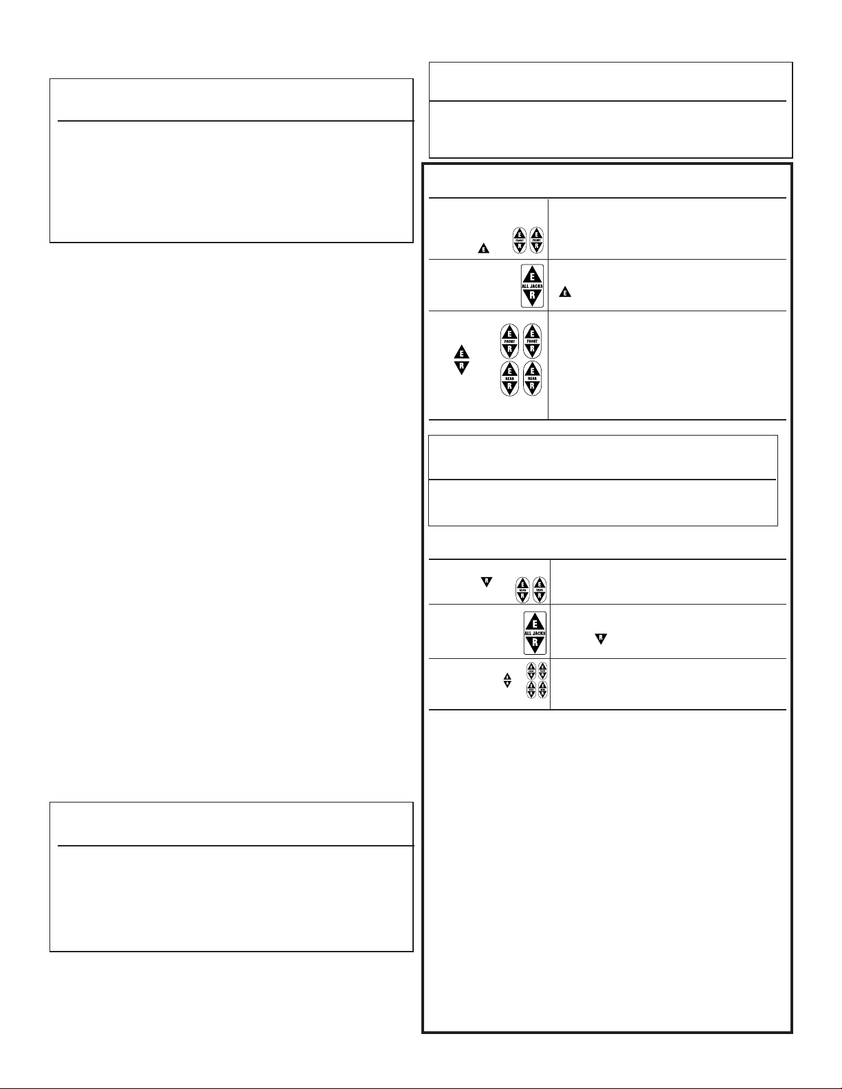
TO LIFT
EXTEND FRONT
JACKS FIRST
EXTEND ALL JACKS
INDIVIDUAL JACK
ADJUSTMENT
PRODUCT DAMAGE
TRUCK CAMPER
Extend front jacks so camper is 4˝ higher in
front than in the rear. (FIG 2).
Once the camper front is higher than the rear,
press and hold the
( ). Release when the camper is at the
desired height.
Use the individual jacks buttons to adjust an
individual jack. NOTE: A maximum of two individual jacks can be operated at any time.
Press and hold the extend or release buttons
for the individual jacks as needed to keep the
front of the camper 4˝ higher than the rear, to
prevent tipping over the camper. Keep all
corners within 4˝ of level with each other.
ALL JACKS BUTTON, extend
WARNING
PERSONAL INJURY & PRODUCT DAMAGE
• Do not enter camper after it is removed from truck until it is
lowered to its lowest position. This will minimize sway which could
cause structural damage to the camper, jacks or injury to persons.
TO LOWER
RETRACT REAR JACKS
FIRST
RETRACT ALL JACKS
INDIVIDUAL JACK
ADJUSTMENT
REMOVING CAMPER FROM TRUCK
Disconnect electrical connection between camper and truck (refer to
your camper operation instructions or contact the camper manufacturer
for more information). Follow the instructions from the “
LOWER TRUCK CAMPER” sections and FIG 2 and 3. Raise camper until bot-
tom of camper clears truck bed. Slowly drive truck from underneath
camper. Lower camper to lowest possible position without any part of
camper touching the ground.
LOADING CAMPER ON TRUCK
Following the instructions “TO LIFT” or “TO LOWER” truck camper sections and
Carefully back truck under camper making sure not to damage any portion of the camper or jacks. Camper should be centered in truck bed
with front of camper as far forward in truck bed as possible. Attach
electrical connections between truck and camper, (refer to your camper
operating instructions or contact the camper manufacturer for further
information). Lower camper into truck bed, then fully retract all jacks.
Manual Override Operation: To manually extend or retract jack, unplug
jack from camper to disable the jack motor’s dynamic brake. Place
manual override handle (
engage drive pin. Rotate handle counter-clockwise to raise or clockwise
to lower camper. Plug the jack back into camper to activate the jack
motor’s dynamic brake.
FIG 2 and 3, raise camper high enough to clear truck bed.
2
Retract rear jacks so camper is 4˝ lower in
rear than in the front. (
FIG 3).
Once the camper has the rear lower than the
front, press and hold the ALL JACKS BUTTON,
retract ( ). Release when the camper is at
the desired height.
Use the individual jacks buttons to adjust an
individual jack. NOTE: A maximum of two individual
jacks can be operated at one time. Keep all
corners within 4˝ of level with each other.
TO LIFT” or “TO
FIG 1-A) into alignment tube (FIG 1-B) and
Page 3

5TH WHEEL TRAILERS
E
R
ALL
E
R
ALL
1 MOTOR SYSTEM (KEY FOB)
TO LIFT
1. Remove the hand held remote control from its secure compartment.
2. Press activate/learn button until red LED illuminaties, then release.
The button has an automatic off circuit that times out after 10 minutes. It can be turned off at any time.
EXTEND
ALL
LEGS
Press and hold this button.
Release when the kingpin is at the desired height.
TO LOWER
Retract slideout rooms fully to their inboard position.
Press the activate/learn button to turn on remote control.
RETRACT
ALL LEGS
Press and hold this button.
Release when the legs are retracted.
TO PROGRAM REPLACEMENT KEY FOB
If you have a replacement key fob, it must be programmed to the
receiver.
1. Remove the hand held remote control from its secure compartment.
2. Press activate/learn button until red LED illuminates, then release.
The button has an automatic off circuit that times out after 10 minutes. It can be turned off at any time by pressing activation button
again.
3. Press and hold the Red Activate/Learn Switch for approximately 5
seconds until the LED begins to flash. The receiver is in the transmitter code learning mode. All previous programs are erased.
4. Press any button on the transmitter (remote) and verify the Red LED
on the receiver stays lit for approximately 1/2 second, then returns to
the flashing modes of illumination. This indicates the transmitter is
identified by the receiver.
5. Repeat step 4 for additional transmitters that will be used with the
receiver.
6. If there are no additional transmitters to be programmed, in 5 seconds the Red LED will return to constant illumination and the receiver
to normal operation.
7. Verify the remote is programmed with the receiver by pressing any
button on the remote and see if the corresponding function is activated.
2 MOTOR SYSTEM
TO LIFT
1. Remove the hand held remote control from its secure compartment.
2. Press activation switch. The switch has an automatic off circuit that
times out after 10 minutes.
3. When finished, the LED on the activation switch must not be lit.
4. PANIC STOP - Once the legs start moving, any button can be
depressed to panic stop the legs. The system stays activated. Push
RETRACT ALL to reset system.
EXTEND
ALL
LEGS
INDIVIDUAL Use the individual leg button for adjustment.
LEG
ADJUSTMENT
Press and hold the EXTEND ALL button.
Release when the kingpin is at the desired height.
Press and hold the EXTEND BUTTON ( ) for an
individual leg as needed until the front of the trailer is level.
TO LOWER
Retract slideout rooms fully to their inboard position.
Press the activation button to turn on remote control.
RETRACT
ALL LEGS
INDIVIDUAL
LEG
ADJUSTMENT
Press and hold the RETRACT ALL button, retract
Release when the legs are retracted.
Use the individual leg buttons for adjustment.
4 MOTOR SYSTEM
TO LIFT
1. Remove the hand held remote control from its secure compartment.
2. Press activation switch. The switch has an automatic off circuit that
times out after 10 minutes.
3. When finished, the LED on the activation switch must not be lit.
4. PANIC STOP - Once the legs start moving, any button can be
depressed to panic stop the legs. The system stays activated. Push
RETRACT ALL
AUTO
EXTEND
to reset system.
Press the AUTO EXTEND BUTTON and all four legs
will extend automatically. Upon reaching the
ground and sensing a minimum load, the legs will
stop.
FRONT
LEGS
REAR
LEGS levelers
INDIVIDUAL
LEGS
Press and hold the
front
levelers
Press and hold the REAR button to extend the rear
Press the IND button and the button for the
individual leg to make an adjustment as needed.
for 4”.
FRONT button to extend the
for 4”.
TO LOWER
Retract slideout rooms fully to their inboard position.
Press the activation button to turn on remote control.
PANIC STOP - Once the legs start moving, any button can be
depressed to panic stop the legs. The system stays activated. Push
RETRACT ALL to reset system.
REAR
LEGS levelers
FRONT
LEGS levelers
INDIVIDUAL
LEGS
Alternate between the
Press and hold the REAR button to retract the rear
for 4”.
Press and hold the FRONT button to retract the front
for 4”.
Press the IND button and the button for the
individual leg to make an adjustment as needed.
REAR and FRONT buttons, keeping the front of the
trailer higher than the rear. Retract the legs in this manner until all legs
are slightly off the ground.
AUTO
RETRACT
Once the load is off the legs, press AUTO RETRACT
and release. The system will automatically finish
the retraction process.
MANUAL OVERRIDE: Refer to MPD 71125 for manual operation of landing gear,
direct drive legs, or rear levelers.
CAUTION
TRAILER CAN MOVE OR COLLAPSE
• Never exceed rated capacity of landing legs.
LANDING LEGS ARE NOT DESIGNED TO BE USED AS TRAILER JACKS. Do not use the land-
•
ing legs to lift the trailer during tire changes, axle work or trailer servicing (the
trailer weight will exceed the capacity of the landing legs). The landing legs
are designed to stabilize a portion of the trailer’s weight. Support the
front end of the trailer with structural stands rated for the GVWR of the trailer.
• Chock both sides of trailer wheels before operating landing legs
• All legs must touch the ground or the surface at the same time.
• Retract landing legs and levelers completely before towing trailer.
TROUBLESHOOTING & MAINTENTANCE CONTINUED ON PAGE 8
3
Page 4

TROUBLESHOOTING
If all or any of the jacks or landing legs fail to operate:
1. Check whether the 12VDC battery is fully charged. You may need to recharge it.
2. Check that the camper jack cords are securely plugged into the exterior sockets.
You may need to pull a plug out and replug it.
3. If the motor will not extend/retract the jack and the motor is making a ratcheting
sound (clutch slipping), do not use the manual override. Immediately contact an
Atwood Service Center and have jack replaced. Do not use the jack until
replaced.
4. Assure the activation switch is turned on. The LED on the switch pad should be lit.
5. Hold the hand-held remote vertically with the keypad facing you and have the
remote between you and the camper.
6. Check that you are within 20 feet of the camper, however at a safe distance to
avoid contact with the camper. All observers must also be at a safe distance.
7. Replace the 9V battery
8. Check that the battery terminals are clean and have no corrosion.
9. Be sure the dip switch code for the remote and the power relay module are set
for the same code.
10. Look to see if other radio frequency devices such as an automobile key fob, cel-
lular phone, TV remote control, are operating within range of your remote.
These devices will make the jacks pause. Lift your finger from the button on the
remote and re-press the button.
If the jacks keep running, push the activation switch and the light on the switch will
go out. This will shut the power off to the jacks. If not, unplug the jack(s) from its
(their) exterior socket(s).
MAINTENANCE
1. To clean the remote, wipe with a soft cloth dampened with water. Don’t use cleaners
or solvents on the remote, they can harm the body and leak inside, causing permanent damage. Battery contacts may be wiped with a dry, lint-free cloth.
2. If the remote gets wet, remove batteries immediately. Dry battery compartment with
a soft cloth to minimize potential water damage. Leave cover off the battery compartment overnight or until completely dry. Do not use the remote until completely
dry.
3. If power relay module gets wet, turn off circuit breaker to the unit. Allow unit to fully
dry before attempting to use it.
4. If it is not possible to get jack to operate freely, replace jack.
5. Should problems or questions arise, contact your dealer, the camper manufacturer,
or the Atwood Service Department (574) 262-2655.
6. The ball screw jacks and remote controls have a two year warranty as written in this
manual. For more warranty information contact Atwood before having any work done.
ATWOOD LIMITED WARRANTY
Atwood Mobile Products warrants to the retail owner and subject to the below mentioned conditions, that this product will be free of defects in material or workmanship
for a period of two years from the original date of purchase. Atwood’s liability hereunder is limited to the replacement of the product, repair of the product, or replacement
of the product with a reconditioned product at the discretion of the manufacturer. This
warranty is void if the product has been damaged by accident, unreasonable use, neglect, tampering or other causes not arising from defects in material or workmanship.
This warranty extends to the original owner of the product only and is subject to the
following conditions:
1. For two (2) years commencing with the date of purchase, Atwood will provide the
replacement or repair of any Hardware System and Components that are found to
be defective by Atwood in material or workmanship.
2. In the event of a warranty claim, the original owner must contact the Atwood
Consumer Service Department, 1120 North Main, Elkhart, IN 46514 USA.
Phone: (574-262-2655). Warranty Claim Service must be performed as approved by
the Atwood Consumer Service Department. Warranty replacement hardware systems and components or parts will be furnished freight prepaid labor cost to repair
or replace will be limited to the amount of the original purchase price of the systems
and components. The replaced warranty products or parts become the property of
Atwood Mobile Products and must be returned to the Atwood Consumer Service
Department freight prepaid, unless prior arrangements have been made.
3. This limited warrant is valid only when the product is applied, installed, maintained
and operated in accordance with this Atwood Installation Maintenance and Operating
Manual. Any deviation from these specifications must be approved in writing by
Atwood.
4. ANY IMPLIED WARRANTIES arising by way of State Law, including any implied war-
ranty of merchantability and any implied warranty of fitness for a particular purpose are
limited in duration to the term of this Limited Warranty. Atwood makes no further warranty of any nature beyond this Limited Warranty. No person has authority to enlarge,
amend or modify this Limited Warranty.
5. Any action to enforce this warranty shall not be commenced more than one (1) year
after the expiration of this warranty. 5.22.07
8
Page 5

A
B
4" (10.16 cm)
3
2
F
G
F
G
A
B
C
D
F
G
DF
DF
PF
PF
DR
DR
PR
PR
12V
GND
F
G
J
E
H
I
12345
O
N
K
P
12345
ON
12345
ON
L
P
DOOR
Q
PICKUP CAMPERS
F(-)
G
F(-)
FRONT
CONTROL
PAD
5TH WHEEL
REAR
G(+)
A
B
CD
N
M
N
M
E
G
I
F
G
G
F
G
F
G
DOOR
Q
F
G
E
1
4
5
5th WHEEL TRAILERS
6
Control Boards
30
MPD XXXXX
CAUTION: ONLY
REPLACE FUSE
WITH 30A FUSE
DATE CODE
XX04
12VG N D
MOTOR
– +
ACTIVAT E /
LEA RN
DRIVER —
DRIVER
+
PASSENGER
+
CAUTION: ONLY REPLAC E FUSES
WITH 30A FUSES
PASSENGER —
GND
12VD C
I
K
J
H
B
30
30
85478
DATE CODE
2204
CAUTION: ONLY REPLAC E FUSES
WITH 30A FUSES
85482
DATE CODE
2204
G N D12V
DF +
DF –
DR +
DR –
PF +
PF –
PR +
PR –
K
J
C
30
30
30
30
DRIVER
PASSENGER
E
R
ALL
JACKS
FRONT
E
R
E
R
FRONT
REARREAR
CAMPER JACK
CONTROL
2- MOTOR
4- MOTOR
KEY FOB
I
L
I
I
H
L
H
I
A
4
 Loading...