

Atwood LPCO, LPCO_DOW, LPCO_DOB, LPCO_AOW, LPCO_AOB User And Installation Instructions Manual
...
Atwood Mobile Products LLC
1120 North Main Street Elkhart, IN 46614-3203
USA : 800-546-8759
USA & Canada 800-825-4328
Internet: http://www.atwoodmobile.com
Models LPCO
USER’S MANUAL AND INSTALLATION INSTRUCTIONS
TESTED TO UL2034, UL1484 AND CSA 6.19
For questions concerning your Alarm, please call our Customer
Service at 1-800-546-8759
Please have the following information ready when calling:
Alarm Model Number (located on the back of alarm):
Alarm Assembly Number (located on the back of alarm):
Date of Manufactured (located on the bottom of alarm):
Date of Purchase:
Where Purchased:

2
CARBON MONOXIDE AWARENESS............................................................................ 3
LIQUEFIED PETROLEUM GAS AWARENESS ............................................................ 4
ACTIVE ALARM PROCEDURES................................................................................... 6
TESTING ......................................................................................................................... 8
MODEL DESCRIPTION .................................................................................................. 9
SPECIFICATIONS........................................................................................................... 9
POWER CONSERVATION MODE.........................................................................................10
ALARM OPERATION ................................................................................................... 10
Power Off Mode.....................................................................................................................10
Normal Gas Detection Mode ................................................................................................10
Alarm Active Mode................................................................................................................11
Alarm Test Mode ...................................................................................................................11
Alarm Reset / Stabilization Mode.........................................................................................11
Fault Mode.............................................................................................................................11
FUNCTIONS.................................................................................................................. 12
INSTALLATION INSTRUCTIONS ................................................................................ 13
WIRING.......................................................................................................................... 15
SURFACE MOUNTING BOX........................................................................................ 16
Surface Mounting..................................................................................................................17
Flush Mounting .....................................................................................................................18
AC Power Adapter Mounting...................................................................................... 19
OPERATING INSTRUCTIONS ..................................................................................... 19
DETECTOR TEST......................................................................................................... 19
LP GAS DETECTION.................................................................................................... 19
POWER MANAGEMENT.............................................................................................. 20
Low Power Warning Mode ...................................................................................................20
Power conservation Mode: ..................................................................................................21
Low Power Alarm Mode: ......................................................................................................21
Power Failure ........................................................................................................................21
End of Life .................................................................................................................... 22
TROUBLESHOOTING QUICK-GUIDE......................................................................... 22
WARRANTY.................................................................................................................. 25

3
READ ENTIRE MANUAL BEFORE USING THIS ALARM
Your new Atwood Carbon Monoxide and Propane (CO/LP) alarms are sophisticated
instruments that has been carefully designed and tested to detect CO and LP build
up in a residential or recreation vehicle environment.
Carbon Monoxide (CO) and Liquefied Petroleum (LP or Propane) gases can cause
hazardous conditions when found in high concentrations. Both gases are known to
be found in recreational vehicles and the proper detection of these gases provides
a safe environment for the occupants of the vehicle.
CARBON MONOXIDE AWARENESS
The following are the symptoms of Carbon Monoxide poisoning and must be
discussed with all occupants of the vehicle.
1. Mild Exposure: Slight headache, nausea, vomiting, fatigue (“Flue like
symptoms).
2. Medium Exposure: Severe throbbing headache, drowsiness, confusion, fast
heart rate.
3. Extreme Exposure: Unconsciousness, convulsions, heart and lung failure,
brain damage, and death.
Many cases of reported CARBON MONOXIDE POISONING indicate that while
victims are aware they are not well, they become so disoriented they are unable to
save themselves by either exiting the building or calling for assistance. Young
children and house hold pets are typically the first affected. This device does not
provide warnings for all levels of CO. Individuals with certain medical conditions
may consider using a warning device that provides both audible and visual signals
for carbon monoxide concentrations below 30 ppm. Everyone is susceptible to the
danger of CO, but experts agree that unborn babies, small children, pregnant
women, senior citizens and people with heart or respiratory problems are at the
highest risk for serious injury or death.
If you experience ANY symptoms of CO poisoning, consult your physician.
Be aware that the following conditions can result in transient CO situations, such
as:

4
1. Excessive spillage or reverse venting of fuel burning appliances caused by:
•
Outdoor ambient conditions such as wind direction and/or velocity, including
high gusts of wind; heavy air in the vent pipes (cold/humid air with extended
periods between cycles).
•
Negative pressure differential resulting from the use of exhaust fans.
•
Simultaneous operation of several fuel burning appliances competing for
limited internal air.
•
Vent pipe connection vibrating loose from clothes dryers, furnaces, or water
heaters.
•
Obstructions in or unconventional vent pipe designs which amplify the
above situations.
2. Extended operation of un-vented fuel-burning devices (range, oven, fireplace,
etc.
3. Temperature inversions which can trap exhaust gasses near the ground.
4. Car idling in an open or closed attached garage, or near a home.
LIQUEFIED PETROLEUM GAS AWARENESS
LP gas is commonly called Propane and is sold commercially as a suitable fuel in
portable and permanent heating and cooking appliances.
It is important to detect LP gas due to its explosiveness at concentrated volumes.
The lowest explosive limit for LP concentration is 21,000 parts per million (ppm).
This detector was designed to alarm at 10% of this limit or 2100 ppm.
SAFETY ALERT SYMBOLS
Safety symbols alerting you to potential personal safety hazards,
Obey all safety messages following these symbols.
5
CAUTION
This alarm will only indicate the presence of gas at the sensor. Gases may be
present in other areas. Read this entire manual before using the alarm.
WARNING
Avoid possible injury or death
WARNING
Actuation of your CO alarm indicates the presence of carbon monoxide (CO)
which can KILL YOU.
WARNING
This product is intended for us in ordinary indoor locations of family living units. It is
not designed to measure compliance with Occupational Safety and Health
Administration (OSHA) commercial or in
dustrial standards.
CAUTION
Avoid possible injury and/or property
damage

6
ACTIVE ALARM PROCEDURES
IF ALARM SIGNAL SOUNDS:
1. Operate Reset/silence button;
1. Immediately move to fresh air-outdoors or by an open door/window. Do a head
count to check that all persons are accounted for: Do not reenter the premises
nor move away from the open door/window until the emergency services
responders arrive, the premises have been aired out, and your alarm returns to
its normal condition?
2. Call your local Emergency Services Number or 911
( )
Fill in your local Fire Department number here
3. After following steps 1-3, if your alarm reactivates within a 24 hour period,
repeat steps 1-3 and call a qualified appliance technician
( )
to investigate for sources of CO and LP from fuel burning equipment and
appliances, and inspect for proper operation of this equipment. If problems are
identified during this inspection, have equipment serviced immediately. Note
any combustion equipment not inspected by technician consult the
manufacturers Instructions, or contact the manufacturers directly, for more
information about CO and LP safety. Make sure that motor vehicles are not, or
have not been operating in an enclosed area or in close proximity of other
vehicles.
Note: two self adhesive emergency contact tables are provided. The user must
add telephone numbers for the local emergency service provider and for a
qualified service technician. User must place one label next to the alarm. The
other label must be placed near a source of fresh air where you plan to gather
in the event the alarm indicates carbon monoxide presence.
7
WHAT TO DO IF YOU SMELL GAS
•
Evacuate all persons from vehicle.
•
Shut off gas supply at gas container or source.
•
Do not touch any electrical switch, or use any phone or radio in vehicle.
•
Do not start vehicle’s engine or electric generator.
•
Contact nearest gas supplier or qualified Service Technician for repairs.
•
If you cannot reach a gas supplier or qualified Service Technician, contact the
nearest fire department.
•
Do not run on gas supply until gas leak(s) has been repaired.
WARNING
Activation of this device indicates the presence of LP gas, which can cause an
explosion and/or fire. This normally indicates a leak in the LP gas piping or an LP
gas appliance.
WARNING
Test Alarm operation after vehicle has been in storage, before each trip, and at
least once per week during use.
WARNING
: If the information in this manual is not followed exactly, a fire or
explosion may result c
ausing property damage, personal injury or loss of life.
8
TESTING
Note: Unit must be powered for three minutes before test can be performed.
The Test/Rest button is used to verify proper alarm operating. Executing the test
function sounds the alarm and lights up all LED's. The test will sound the alarm
twice, with 4 “beeps” in 1 second followed by 5 seconds of silence.
By pressing the button, you can verify that the alarm sounds and that all visual
indicators function properly. The alarm is internally monitored while powered to
ensure proper operation and to detect faults.
Important
•
This detector will only indicate the presence of CO or LP gas at the sensor.
Gases may be present in other areas.
•
The detector is not suitable as a smoke or fire detector. Not suitable for
installation in hazardous locations as defined in the National Electrical Code.
WARNING
Test Detector operating after vehicle has been in storage, before each trip, and at
least once per week during use.

9
MODEL DESCRIPTION
LP=Propane CO=Carbon Monoxide D=12Vdc A=120Vac O=OEM R=Retail
OEM Package Retail Package
Model Part No Color Model Part No Color
LPCO_DOW 36636 White LPCO_DRW 36681 White
LPCO_DOB 31011 Black LPCO_DRB 31012 Black
LPCO_AOW 36520 White LPCO_ARW 36521 White
LPCO_AOB 31003 Black LPCO_ARB 31004 Black
Surface Box 31128 Black Surface Box 36689 White
SPECIFICATIONS
LP CO
Alarm Level:
2100 ppm for 10
seconds
70 ppm for 60 to 240 minutes
150 ppm for 10 to 50 minutes
400 ppm for 4 to 15 minutes
Audio Alarm Min. 85 dB at 10 Feet
Visual Alarm
LP blinking red LED and
Chirping
CO blinking red LED and
Chirping
Malfunction Red Fault LED on and chirping sound
Sensor End of Life
Alarm
Blinking red LED’s and Chirping
Dimensions 3-9/16” H X 3-7/16” W
Supply Voltage
Thresholds
9 to 18 VDC (13.5 V nominal)
Supply Current (Max) 75 am
Supply Current
(Typical)
40 mA
IAS Tested @ 67% to 133% of supply voltage
Current Draw Typical 70 mA – Alarm 100 mA

10
POWER CONSERVATION MODE
Current Draw 10 mA
Temperature -40° to 70° C (-40° to 158°F)
Storage Temperature -40° to 70° C (-40° to 158°F)
Humidity 15 to 90%
Warranty Limited, 2 year
Alarm Lifetime 7 years ( powered operation)
Standards
ETL tested to UL 2034 & UL 1484 Residential and RV and
Complies with CSA 6.19
For Service and Information Contact
Atwood Mobile Products LLC, 1874 South Pioneer Road Salt Lake City, Utah 84104-4226
Consumer Service Department, 1120 North Main, Elkhart, IN 46514 USA.
Phone: 866-869-3118
ALARM OPERATION
The alarm includes four LED indicators, an LP, CO and LPCO oscillating multi-tone
audible alarms, and one Test/Reset button that provide interaction and feed back
with your alarm. The indicators allow you to troubleshoot your alarm and to
determine the proper actions to take. The visual indicators are labeled Power, Fault,
Carbon Monoxide, and Propane.
The alarm operates in six separate modes that will be identified in this section.
Power Off Mode
This mode indicates that there is insufficient power provided to the alarm. The
indicators and button will not function in this mode. Sufficient power must be
provided to the alarm to exit this mode.
Normal Gas Detection Mode
This mode indicates that gas concentrations are continuously monitored. It also
indicates that gas concentrations are at safe levels. In this mode the Power
indicator will be lit, and all other indicators will not be active. The Test function for
the Test/Reset button will be active.

11
Alarm Active Mode
This mode indicates that one or more gas concentrations have achieved unsafe
levels. In this mode the Power indicator will be lit. In the case that the CO
concentration is unsafe the Carbon Monoxide indicator will be lit. In the case that
the LP concentration is unsafe the Propane indicator will be lit. In this mode the
audible indicator will signal an alarm, and the Reset function of the Test/Reset
button will be active. This mode will be exited automatically if the CO concentration
falls to a safe level for an extended period of time and LP concentrations falls below
500 ppm for greater than 10 seconds.
Alarm Test Mode
This mode indicates that the Test function of the Test/Reset button was imitated. In
this mode, all visual indicators will be lit, and the audible indicator will signal an
alarm. The test/Rest button will not function during this mode. This mode will be
exited automatically within 10 seconds.
Alarm Reset / Stabilization Mode
This mode indicates that the alarm is stabilizing for the first 3 minutes after powerup or the first 6 minutes after the Rest Function was initiated. In this mode the
Power indicator will be lit, and the reset alarm’s indicator will be flashing. The other
visual indicators, the audible indicator, and the Test/Reset button function will be
off. This mode will be exited if the previously inactive alarm is triggered. If gas
concentrations are still high after the 6 minutes, the previous alarm will reactivate.
Fault Mode
This mode indicates that a fault has been detected that compromises some alarm
function. If a fault is detected on only one of the sensors, the other sensor would
function normally. The table below lists the indicator actions and the corresponding
alarm status. This mode will be exited automatically when the fault is cleared.
If the fault persists, the alarm is not functioning properly and must be replaced to
ensure your safety in the area.

12
End of Life Mode
The Detector will operate in end-of-life mode after the Detector has been powered
for 7 years +/- 128 days. This represents the operating life of the sensors used to
detect CO and LP gas.
After 7 years, the sensors are no longer reliable and the Detector must be replaced.
Once end-of-life mode has been entered, it is permanent, even after a power out
cycle. If the reset/test button is pressed during end-of-life mode, the audible alarm
will be silenced for 48 hours before being automatically reactivated. The power
visual indicator will be on and the CO and/or LP visual indicators will be flashing.
The audible alarm will be sounding per table below.
Note: two self adhesive emergency contact labels are provided. The user must
add telephone numbers for the local emergency service provider and for a
qualified service technician. User must place one label next to the alarm. The
other label must be placed near a source of fresh air where you plan to gather in
the event the alarm indicates carbon monoxide presence.
FUNCTIONS
Feature Function Status
Flashing Power supply fault
Power LED
On Power supply OK
Flashing Propane alarm disabled
Propane LED
Off Propane alarm OK
Flashing Carbon Monoxide alarm disabled Carbon
Monoxide LED
Off Carbon Monoxide alarm OK
Fault LED On Fault active
Chirp Fault Active
4 Chirps CO Alarm Active
6 Chirps LP Alarm Active
Audible Indicator
4-6 Chirps Co-LP Oscillating multi-tone Alarm Active
Chirp Sensor failure
End of life
ON Both CO & LP LED’s steady on
Figure 1: Fault Indicator Actions

13
IMPORTANT – If this alarm does not test properly return it immediately for
repair or replacement.
The visual indicators have two distinct functions: On and Flashing.
The “On” function is indicated by constant solid brightness of the LED. The
“Flashing” function is indicated by the LED blinking once every second.
The audible indicator has two distinct functions: Alarm and Fault.
In the “Alarm” function, the alarm will sound four “beeps” in 1 second followed by 5
seconds of silence. After 4 minutes of alarming, each silence will last for 1 minute.
In the “fault” function, the alarm will last for 1 minute. In the “Fault” function, the
alarm will sound a “chirp” once every 40 seconds until the fault is cleared.
INSTALLATION INSTRUCTIONS
•
LP/CO units when possible should be mounted lower to detect LP gas first due
to its explosive nature and CO will be detected through air current circulation.
•
Select a location as close as possible to appliances that could be potential
sources of LP gas leaks and where the initial concentration may be greatest.
•
DO NOT INSTALL next to doors or windows that may dilute the concentration
of any LP gas presents in the environment and preclude a timely alarm signal.
•
DO NOT INSTALL the detector in a closet or in a location that could be come
obstructed by a curtain, hanging clothes or any other objects.
•
DO NOT LOCATE detector where it could be exposed to splashes of water or
grease or where it could be damaged by impact with moving objects (i.e.
furniture, feet, etc.).
CAUTION
Installation should be performed by a qualified technician
14
•
DO NOT INSTALL on a wall switch controlled by a power line or ground fault
circuit.
•
Usually you will find more than one suitable location that will also provide ease
of viewing and connection to power.
•
DO NOT INSTALL in any location within 5 feet (1.5m) of any cooking
appliance.
•
Never use detergents or solvents to clean the alarm chemicals can
permanently damage or temporarily contaminate the sensor.
•
Avoid spraying air freshener, hair spray, paint or other aerosols near the
alarm.
•
The following is a list of substances that at high levels can affect the sensor
and cause an alarm.
Methane, propane, iso-butane, ethylene, ethanol, alcohol, carbon monoxide, isopropylene, benzene, toluene, ethyl acetate, hydrogen, hydrogen sulfide, sulfur
dioxides.
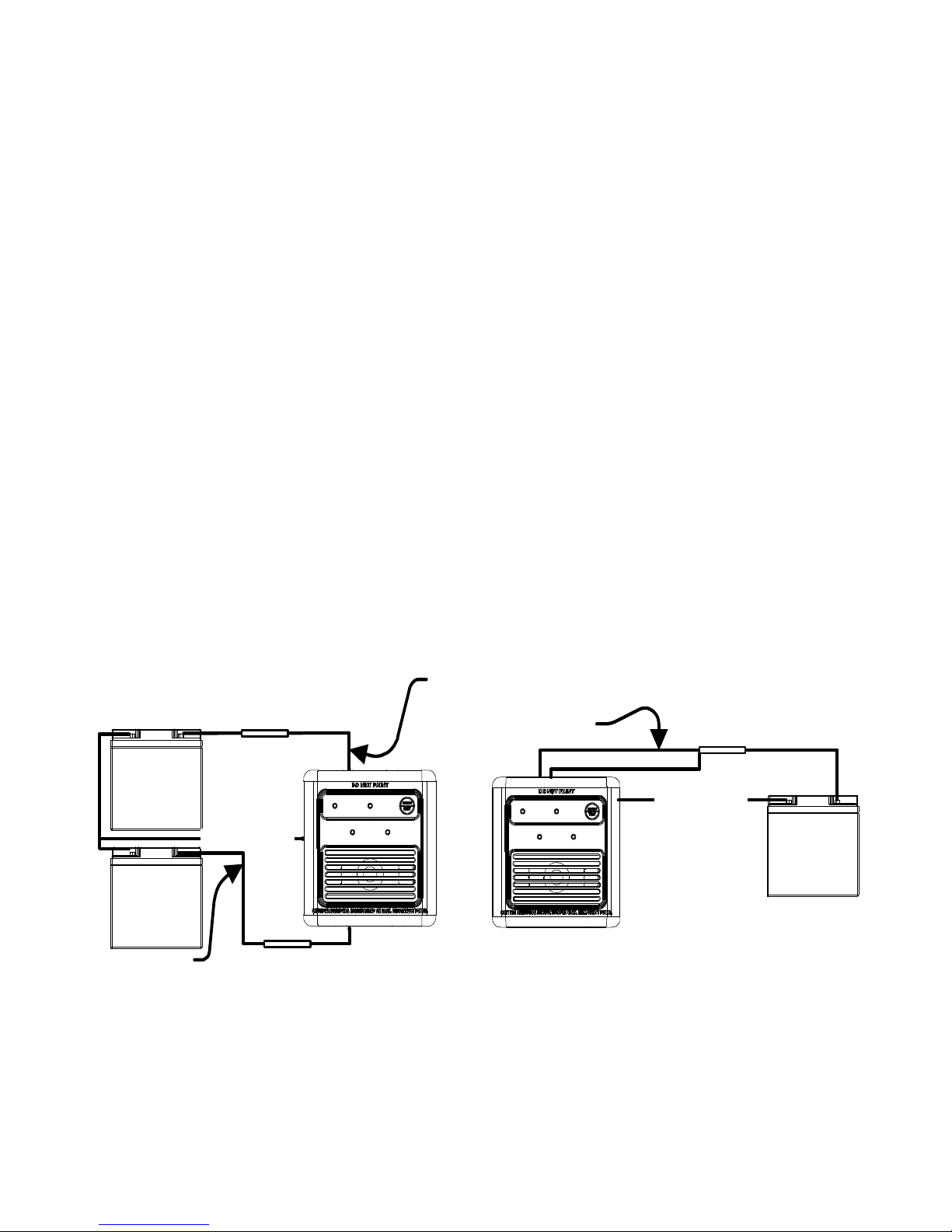
Single Power Source Wiring
+
-
Black 18 AWG
1 Amp Fuse
Power
Supply
Red 12VDC Wires
Dual Power Source Wiring
+
-
+
-
1 Amp Fuse
Black 18 AWG
1 Amp Fuse
Red 12VDC Wire
Red 12VDC Wire
Power
Supply
Power
Supply

15
WIRING
•
Before routing the wires, disconnect the 12 VDC power supply to avoid
shorting. Make sure that the power connections are made to a properly fused
circuit (15 amp maximum) 1 amp fuse is recommended for single or multiple
detector installation. Can be fused through a distribution panel or power
supply box.
•
Connection to a Master Storage Switch is acceptable. The alarm will be off
along with all other 12 volt equipment when the storage switch is turned to the
off position. DO NOT USE THE RV WHEN THE STORAGE SWITCH IS IN
USE.
•
All connections must be in accordance with the National Electrical Code in the
United States and the Canadian Electric Code in Canada. All connection must
use approved wiring and connectors of an appropriate size see wiring diagram
labeled, “Figure A”.
•
Some models are hard wired with a 110 AC adapter allowing the unit to be
plug directly into a 110 AC wall outlet as shown.

16
SURFACE MOUNTING BOX
•
A detachable mounting box allows the unit to be mounted as a surface
installation. If desired you can purchase the optional mounting box for surface
installation by ordering part no. 31128 black or 36689 white part.
•
Mounting box is attached to the surface location were the alarm is to be
mounted with two screws see instructions below.
•
To remove cover flange from alarm insert a flat blade screw driver into the
middle of the slot at the top of the flange and pry down to lift the flange off the
alarm.
•
To install the mounting box to the alarm place the alarm inside the box and
fasten in place with the four screws provided.
•
Reinstall the cover flange by placing the flange against the alarm and
snapping it into place.
17
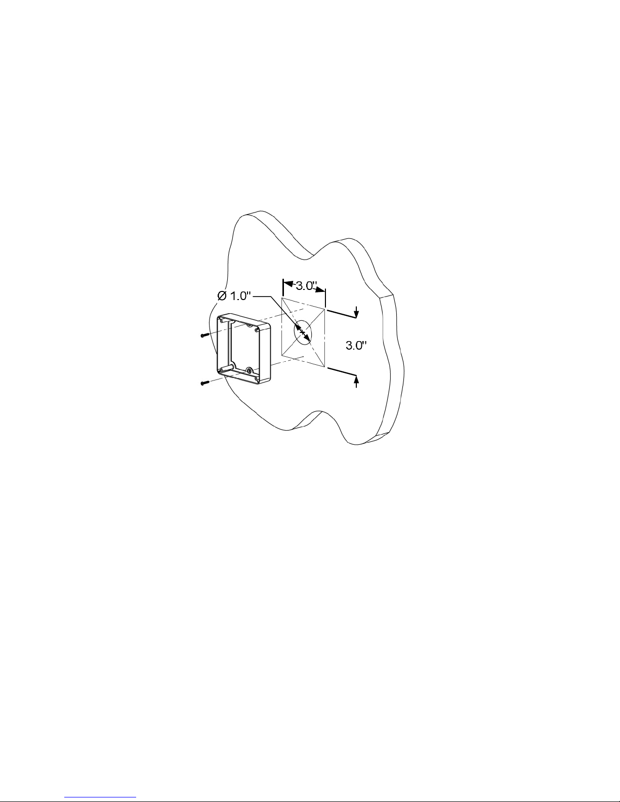
Surface Mounting
1. Mark on the desired mounting surface a box approximately 3” inch wide by 3”
high draw and cut hole.
2. Route power leads to the opening and connect wires to the detector per the
wiring diagrams.
3. Remove cover flange as describe above in surface mounting box section.
4. Center and mount the base over the outline done in step 1 with two screws
provide through the two holes in the box.
5. Snap the cover onto the base
6. Verify that the LED lights(s) align within the cutouts of the face.
18
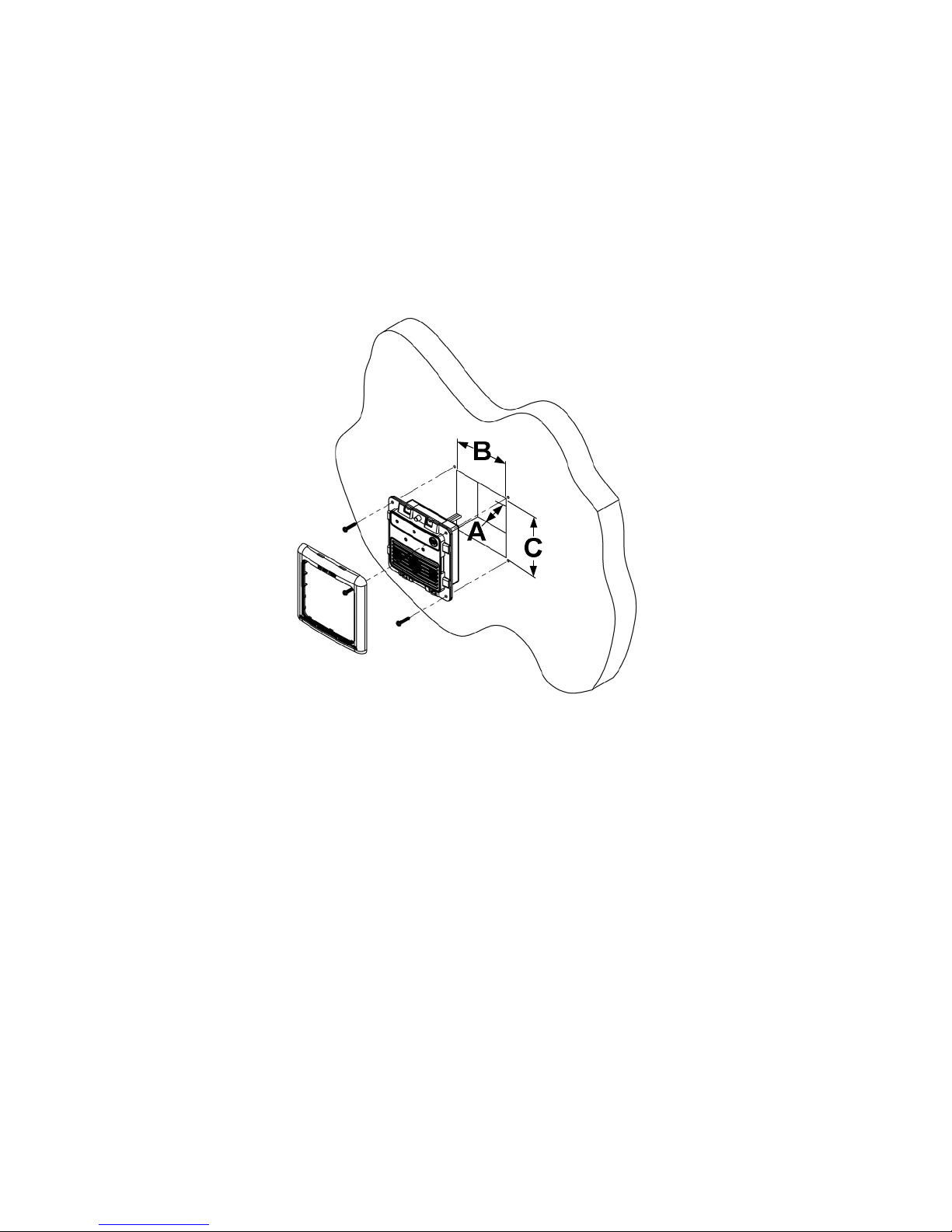
Flush Mounting
1. Verify that there is a minimum of (A) 1-1/2” inches of free space behind the
wall.
2. Mark on the desired mounting surface a box approximately (B) 3-1/2” inch
wide by (C) 3-5/8” high and cutout.
3. Route power leads to the opening and connect wire to the detector per the
wiring diagrams.
4. Install the detector and excess wiring through the opening until mounting
flange is flush to the wall.
5. Mount the unit using the 4 screws provided one in each corner of the flange.
 Loading...