

Page 1
LITERATURE NUMBER
MPD 66166
9
LEVELEGS™ SYSTEM
•Installation •Operation •Maintenance
ENGLISH,
FRANÇAIS (et Canada) Effective 11.21.07
SAFETY ALERT SYMBOLS
Safety Symbols alerting you to potential personal safety hazards. Obey all safety
messages following these symbols.
WARNING CAUTION
avoid possible avoid possible
injury or death injury and/or property damage
FOR YOUR SAFETY READ ALL INSTRUCTIONS
BEFORE INSTALLATION AND OPERATION
Installer: Provide these instructions to the consumer.
Consumer: Keep documents for future reference.
Atwood Levelegs™ Levelers are intended for use on recreation vehicle
motorhomes and trailers, any other use is strictly prohibited.
WARNING
VEHICLE CAN MOVE OR COLLAPSE
• Never exceed the rated capacity of the leveler as stated on its label.
• Levelers are not designed to be used as jacks. Do not use levelers to
lift the vehicle during tire changes, axle work or other servicing. The
tires must stay on the ground.
INSTALLATION
LEVELER LEG
1. Prior to installation, retract the levelers so the foot pads are within
1/2˝ to 1˝ from the end of the outer housing (FIG 1-A).
2. Position leveler vertically against frame so base of foot has 8-9˝
minimum ground clearance when vehicle is loaded to its maximum
GVWR (FIG 1-B).
3. A. For 7.5K Square Tube Levelegs™, attach the frame bracket (
to frame (FIG 12-D) using 4 sets of 1/2˝ - 13 grade 5 nuts and bolts
and 1/2˝ flat and locking washers. Fit the Leveleg bracket (FIG 12-E)
around the Leveleg, (
bracket (FIG 12-G) and the other tab below the bracket (FIG 12-H).
Attach the Leveleg bracket to the frame bracket with a 1/2˝ - 13
grade 5 bolt and 1/2˝ flat washer on the Leveleg bracket and a 1/2˝
flat washer, 1/2˝ locking washer and 1/2˝ - 13 grade 5 nut. To install
on 5th wheel trailers, refer to MPD 71125.
B. For 10K Square Tube Levelegs™, attach the leveler bracket (
to the frame bracket (FIG 13-C) using four (4) each 1/2˝-13 grade 8
bolts and 1/2˝ flat hardened washers.
C. For 15K Square Tube Levelegs™, attach the leveler bracket (
the frame bracket (FIG 14-C) using six (6) each 1/2˝-13 grade 8
bolts and 1/2˝ flat hardened washers.
4.
Lubricate the bolts and torque to 65 ft-lbs.
FIG 12-F) engaging one tab in the slot of the
24 HOUR TROUBLESHOOTING HELP CALL - 800-884-7012
Provided by Coach Net®, the largest RV owner support company in North America.
Not affiliated with/supported by/or warranted by Atwood Mobile Products
CONTROLS
FOR 5TH WHEEL CONTROLS REFER TO MPD 87920 AND 71125.
Relay Pack Controller
WARNING
EXPLOSION
• Controller is not ignition protected. DO NOT install in areas that
require ignition protected devices (such as battery or propane tank
storage compartments).
1. Install Relay Pack Controller in a clean, dry interior area protected
from moisture. Use corner holes of unit to fasten base horizontally
to mounting surface, using appropriate hardware for surface.
2. Install the AUTO POSITION Relay Pack Controller so the forward
arrow points toward the front of the motorhome. The Relay Pack
must be right side up and within 10º of horizontal level (
Auto Position Control Pads
FIG 12-C)
FIG 13-J)
FIG 14) to
1. Locate the controller midway between front and rear wheels of the
vehicle. Provide a 4-15/16˝ (
1/4˝ angled edge (
desired location. Note: Reference control pad when making cutout;
there is tight clearance.
2. Use corner holes (
surface using appropriate hardware for surface.
Note: Fastener must pierce mylar surface of control pad.
3. Connect control pad wire harness (FIG 3H) to control pad.
4. Route the control pad wire harness to controller and connect the
FIG 3-J).
two (
5. Control pad wire harness is configured as follows (FIG 4).
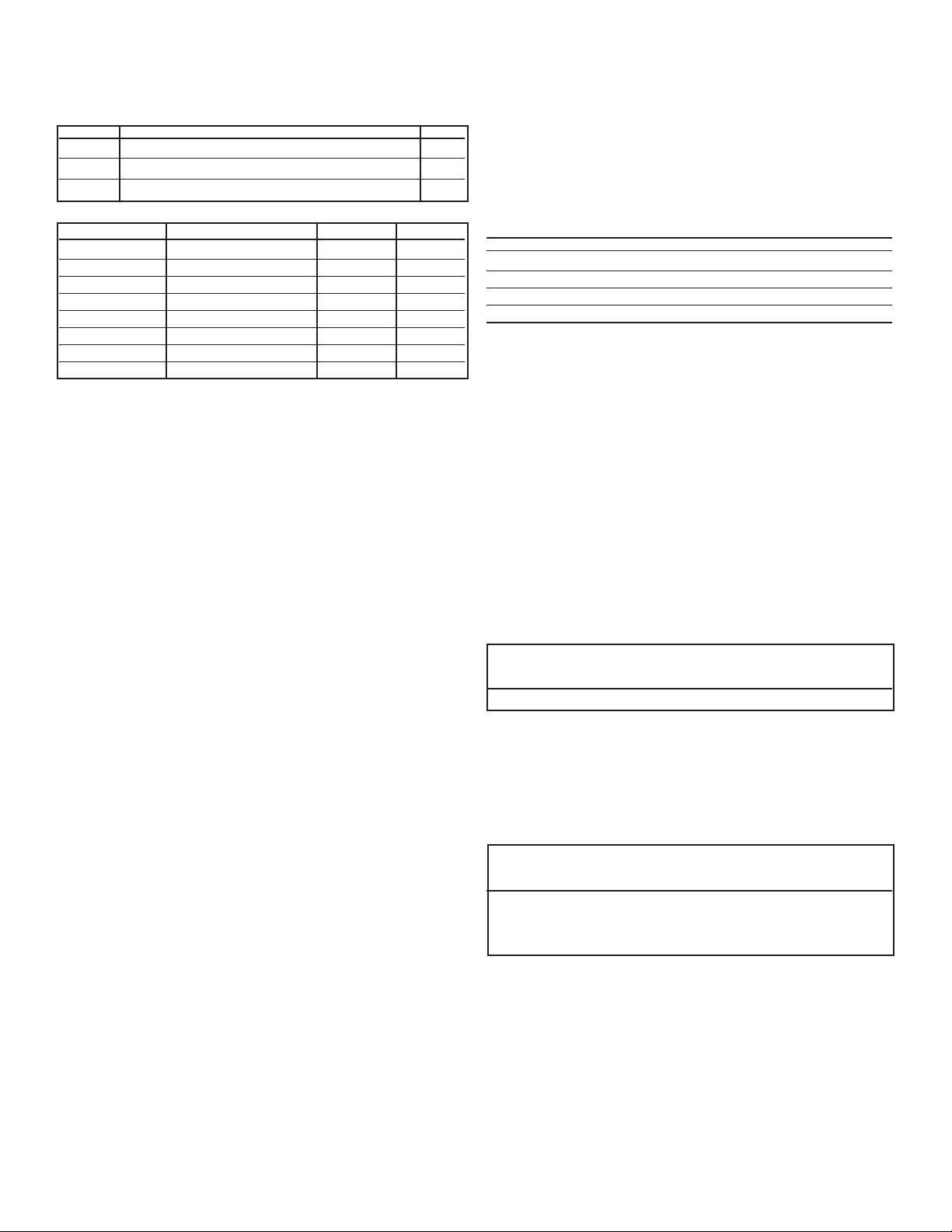
Required Parts
ITEM DESCRIPTION QTY
A+B 43025-0400 Molex®Micro-fit 3.4 circuit receptacle 2
C 43030-0007 Molex®Micro-fit 3.0 female terminal 8
D Unshielded 22 AWG multiconductor cable 1
Pin Requirements
CONNECTOR PIN COLOR CONNECTOR PIN COLOR
A1 White B1 White
A2 Green B2 Green
A3 Red B3 Red
A4 Black B4 Black
6. Crimp the contacts with approved Molex®die.
7. Crimped contact must be able to withstand a minimum of nine
(9) pound pull force.
8. Terminate sleeve of multiconduit cable to within 1˝ of connector
FIG 4-E)
(
9. Adjust the length of harness as required to easily connect control
pad to controller (
FIG 2C) at 45˚ (FIG 2D) for the control pad at
FIG 2E) of unit to fasten control pad to mounting
FIG 4-F).
FIG 2A) x 3-3/16˝ (FIG 2B) cutout with a
FIG 3).
1
Page 2
MOTOR HOME SIGNAL WIRE HARNESS
1. Connect the motor home signal wire harness (FIG 3-I) to the controller (FIG 3-K).
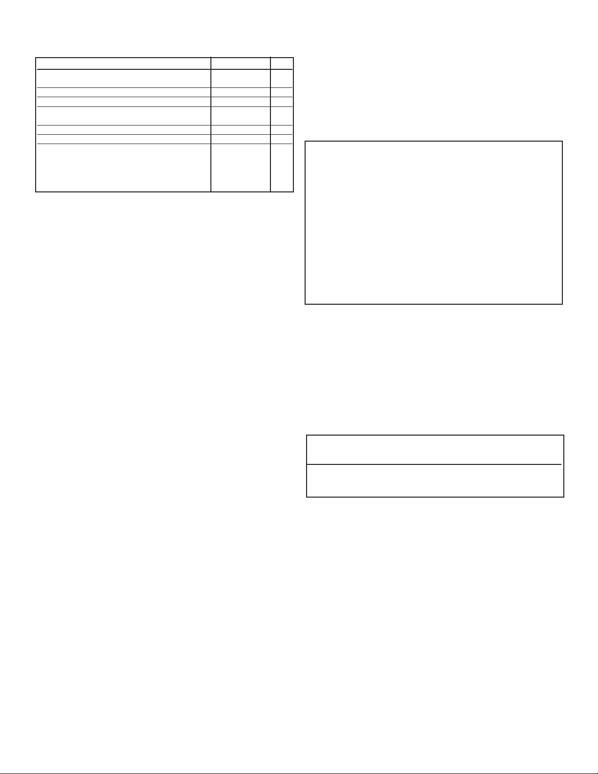
2. Motor home signal wire harness to be configured as follows (FIG 8):
ITEM DESCRIPTION QTY
A 43025 Molex®Micro-fit 3.0,8 circuit receptacle 1
B 43030 Molex®Micro-fit 3.0 female tin terminal 4
C Unshielded 20 AWG multiconductor cable 1
Pin Requirements - (
CONNECTOR PIN DESCRIPTION (REFERENCE) FIGURE COLOR
FIG 8)
P1 Park Brake D white
P2 Transmission E green
P3 N/A F N/A
P4 N/A G N/A
P5 Foot Brake H red
P6 N/A I N/A
P7 Ignition* J black
P8 N/A K N/A
* Install with a 3 AMP in-line fuse to chassis ignition wire.
®
3. Crimp the contacts with the approved Molex
die.
4. Crimped contacts must withstand a minimum nine (9) pound pull force.
5. Terminate the sleeve of multi-conduit cable to within 1˝ of connector
(FIG 8-L)
6. Length of harness “as required” to easily connect control pad to
controller (
FIG 8-M).
POWER CONNECTIONS (FIG 3)
A - Driver Front Leveler G - Yellow (+) Motor Gear Box Lead
B - Passenger Front Leveler H - Control Pad Wire Harness
C - Driver Rear Leveler I - Motor Home Signal Wire Harness
D - Passenger Rear Leveler L - Female Connector (Delphi
E - 125 Resetable Circuit M - Male Connector (Delphi®)
Breaker for 2 AWG O - Air Bag Dump Valve (optional)
battery wire P - Air Bag Fill Valve (optional)
F - Red (-) Motor Gear Box Lead R - Male connector (Deutsch
S - Female connector (Deutsch®)
Controller to Battery
1. Connect the controller to the chassis 12 VDC battery through the
manual reset circuit breaker or fuse (
FIG 3-E).
2. Connect the controller to the battery through 2 AWG wire (FIG 3-N).
3. Terminate
2 AWG 1/4” ID ring terminal (FIG 5-B)
2 AWG wire (FIG 5-A) power wire to controller through a
4. Attach ring terminal to controller with following components:
• #10 conductive washer FIG 5-C
• #10 lock conductive washer FIG 5-D
• 10-32 conductive nut FIG 5-E
Note: Torque nut (
FIG 5-E) to 20-25 in/lbs.
Levelers to Controller
Controller must be connected to levelers through a wire harness
using 8 or 10 AWG wire.
• Use 8 AWG wire for leveler rated above 10,000 lbs
or wire runs longer than 30 feet.
• Use 10 AWG wire for levelers rated at or below 10,000 lbs
or wire runs shorter than 30 feet.
Leveler End (
A. Use the following Delphi
FIG 6)
®
or comparable components to terminate
both leads coming from the controller to lower motor connector
of the 7.5K or 10K levelers.
• 12065863 Connector Male FIG 6-A
• 12052172 Terminal Male FIG 6-B
• 12034170 Cable Seal FIG 6-C
• 12059897 Secondary Lock FIG 6-D
1. Strip wires (FIG 6-F) back about 3/8˝ (FIG 6-E).
2. Slide cable seal (
FIG 6-C) onto wire with neck of cable seal facing
stripped metal in wire.
3. Push cable seal forward to align neck of cable seal with edge of
insulation of stripped back wire end.
4. Put stripped wire into crimp wings closest to mating end of termi-
FIG 6-B) and neck of cable seal (around insulation) into sec-
nal (
ond set of wings furthest from mating end.
®
)
®
)
5. Crimp metal from wire to first set of wings.
6. Crimp cable seal neck (around insulation) to second set of wings.
Then snap secondary lock (
FIG 6-D) onto connector (FIG 6-A).
7. Minimum of strength of core crimp without insulation crimp
should withstand a pull of 300 N (75 lbs).
8. Crimp dimensions:
CORE: 2.4mm (.094˝) high 5.05mm (.20˝) wide
INSULATION: 7.6mm (.30˝) high 7.4mm (.30˝) wide
NOTE: Insert the terminals into the connectors with the flat bottoms
of the terminals oriented toward the connector locks.
B. To terminate 8 gage wire leads from the controller to 15K levelers
use the following components:
ITEM PART ATWOOD P/N DEUTSCH P/N
S connector, female 66627 DTHD04-1-8P FIG 15-S
S2 contact pin 66635 0460-204-08 FIG 15-S2
R connector, male 66636
DTHD06-1-8S FIG 15-R
R2 contact socket 66634 0462-203-08 FIG 15-R2
Auto Position Controls
1. To terminate leads from the wire harness connected to the levelers
use the following components:
• 8 or 10 AWG wire FIG 5-A
• 8 or 10 AWG, ring terminals FIG 5-B
10 AWG 8 AWG
42816-0512 42516-0512 Connector FIG 7-A
42815-0011 42815-0331 Terminal FIG 7-B
2. Trim lead 5/16˝ FIG 7-C.
3. Pin connectors to match pins in Auto Position Control Board as
shown in
FIG 3.
4. Insert Molex®connector from wire harness into control board.
5. To address communication with the air suspension system, the controller must have a single signal lead provided for “Air Dump”
(FIG 3-O) and a single signal lead provided for “Air Fill” (FIG 3-P).
PRE-DELIVERY PREPARATION
Wipe any excess fluid from the top of the foot before delivery.
OPERATION
BEFORE OPERATING THE LEVELERS
CAUTION
PERSONAL INJURY
• Stand clear of the vehicle.
Before operating the levelers, you must do the following:
1. Park the vehicle on a level site. Check for rocks, holes, or other
obstructions. Warn all persons to stand clear of vehicle.
2. For a motorhome,
• Put the vehicle transmission in
• Engage the vehicle PARKING BRAKE.
• Have the vehicle engine running.
3. Do not extend the slideouts until coach is level.
PARK.
WARNING
VEHICLE CAN TIP
Levelers must be on firm solid ground or surface prior to operation.
•
Soft/spongy ground may allow levelers to sink.
• Area below and around leveler must be clear of obstructions.
• Do not place blocks under the leveler for additional ground clearance.
LEVELERS ARE SHIPPED IN THE ERROR MODE STATE.
To take controls out of error mode state, complete a successful
ALL RETRACT (as defined in items 1-3) under TO RETRACT.
4. Put stripped yellow (+) wire end into contact pin (
crimp together. Crimp must withstand a minimum pull of 75 lbs.
5. Put stripped red (-) wire end into contact socket (FIG 15-R2) and
crimp together. Crimp must withstand a minimum pull of 75 lbs.
6. Insert the contact pin (
FIG 15-S2) into the female housing (FIG 15-S)
until it is secured. Then slip seal into housing.
7. Insert the contact socket (
FIG 15-R2) into the male housing (FIG 15-
R) until it is secured. Then slip seal into housing.
2
FIG 15-52) and
Page 3
CONTROL PAD LED INDICATORS
The control pad LED’s indicate the following when illuminated (FIG 9):
Vehicle Engine running (ignition switch
DESCRIPTION COLOR ITEM
is in the ON position) (MOTORHOME ONLY) green A
Park Brake engaged (MOTORHOME ONLY) green B
Park engaged (MOTORHOME ONLY) green C
Low Voltage (less than 13 VDC present
at controller) red D
ON/OFF (referencing power to control box) green E
Extend/Retract Mode green F
Leveler positions
Fully Retracted solid green G
Extended green blinking G
Extending/Retracting red blinking G
Fully Extended solid red G
TO LEVEL
For 5th Wheels, refer to MPD 71125 and MPD 87920 for Operation.
AUTO POSITION CONTROLS
Your keypad may have LEDs to indicate ‘EXTEND’ OR ‘RETRACT’ mode.
If the Auto position is already set or programmed,
• Press the ON button (
• Press the AUTO button (FIG 9-B).
• The levelers will extend and automatically reach the pre-set position.
• The system will check each Leveler to insure its foot is in contact
with ground. During this time, the control board “WAIT” LED will be
FIG 9-C).
on (
TO SET AUTO POSITION
1. Look at the keypad for your system. You have an automatic controller
if there is a button that says “AUTO” (FIG 9-B).
2. To set the AUTO position
a. Manually get the RV to the position you want.
b. Then press the ON (
c. Press ‘EXT’ button (FIG 9-D) 5 times.
d. Press ‘RET’ button (
e. Unit will respond by blinking all LEDS slowly.
f. Press ‘ALL’ button (FIG 9-F) 3 times.
g. Press ‘ON’ (FIG 9-A) then ‘RET’ ‘All’ to retract all Levelegs (FIG 9-E
and 9-F).
TO SET AIR DUMP MODE
1. If LEDs blink left-to-right and back again, your RV has the Air
Dump feature.
a. To enable Air Dump, press the “DRIVER” button
(3) times. The driver side LEDs (FIG 9-H) will illuminate for 3 seconds and shut off. Press “ON” (9-A), then “RET” “All” to retract
all Levelegs (
b. To disable Air Dump, press the “PASSENGER” button (FIG 9-I)
three (3) times. The passenger side LEDs (FIG 9-J) will illuminate
for 3 seconds and shut off. Press “ON” (FIG 9-A), then “RET”
“All” to retract all Levelegs (
c. If the Air Dump feature is not set or has never been configured,
the system will wait for 30 seconds. It will default to “Not
Configured” and the passenger side LEDs will illuminate for
3 seconds and shut off.
2. To change Air Dump from enabled to disabled or vice versa, have
the engine running, the park brake engaged and the transmission in
PARK.
a. Press “ON”
b. Press the “EXT” button (FIG 9-D) ten (10) times.
c. Press the “RET” button (FIG 9-E) ten (10) times.
d. The LEDs will blink left-to-right and back again. Go up to step
3 above and follow the directions to either enable (step 3-a) or
disable (step 3-b) the Air Dump feature.
e. To check the status of the Air Dump, wait 30 seconds and see
which LEDs illuminate. If the air dump is enabled, the driver
side LEDs
abled, the passenger side LEDs
FIG 9-A) to activate the system.
FIG 9-A) button one time, to turn controls off.
FIG 9-E) 5 times.
(FIG 9-G) three
FIG 9-E and 9-F).
FIG 9-E and 9-F)
(FIG 9-A) to turn the controls off.
(FIG 9-H) will illuminate and if the air dump is dis-
(FIG 9-J) will illuminate.
TO MANUALLY DUMP THE AIR BAGS
a. Engine must be running.
b. Transmission must be OUT of Park/Neutral.
c. Parking brake must NOT be engaged.
d. Atwood Levelegs keypad is NOT on. Lights inside the ON switch
are not lit.
e. Press the FRONT + REAR + ALL buttons to dump air from air
bags. (Note: Air dump feature does need to be enabled for this
feature to work.)
f. Air bags dump in approximately 20 seconds and air bags refill
60 seconds from the start of the air dump.
These controls have the following features to facilitate leveling:
• TO MAXIMIZE AVAILABLE LEVELER STROKE During the initial activation of a
pair of levelers following the
onds the first pair of levelers extend, the opposite pair of levelers will
retract for two (2) seconds. This process will repeat for the first 60 continuous seconds of extension of first pair of levelers.
• FULL EXTENSION If a leveler is fully extended, its corresponding LED will
indicate this and further operation of that pair of levelers in the extend
direction is prevented. If the switch is held on, the second leveler of the
pair will operate with its alternate pair partner leveler. (i.e., if the front
two levelers are extending and the left front leveler becomes fully
extended, the right front leveler will continue to operate and the right
rear leveler will start to extend.) This is to keep the frame from twisting.
• LOAD COMPENSATION If one leveler becomes disproportionally more
loaded than its pair partner, power will shut off to the first leveler. The
second leveler will continue to operate until the load is more balanced
between the pair of levelers. Power to the first leveler will then resume.
ALL extend activation, for every six (6) sec-
TO RETRACT
1. Ensure slideout rooms are fully retracted (in their inboard position).
2. Press the
3. Press the ALL button (FIG 9-F) and RETRACT button (FIG 9-E) simultaneously and release. Levelers will retract automatically to their fully
retracted position. The leveler indicator LEDs will blink red (FIG 9-H
or 9-J) during this activity.
4. Once levelers are fully retracted, level indicator LED (FIG 9-H) will be
solid green.
NOTE: After operating levelers, the position LEDS for all the levelers must be
ON button (FIG 9-A).
solid green before the vehicle is to be moved. A visual examination of
all the levelers outside the motor home is recommended to insure
levelers are fully retracted.
CAUTION
PRODUCT DAMAGE
• Do not move vehicle until levelers and landing legs are fully retracted.
• Damage can occur to levelers, coach and surrounding property if the
levelers are not fully retracted prior to vehicle being moved.
5. Press the
SYSTEM PROTECTION FEATURES
Automatic Retract
• Anytime the engine is on, if the vehicle brake is depressed and
transmission is taken out of park, the levelers will fully retract
automatically.
• During auto retraction, an alarm will sound and all LEDs will blink on
and off.
Nine Cycle Maximum
• The controls will shut off for 15 minutes any time nine (9) full
retractions occur in less than 30 minutes.
• When this occurs, all four system status lights blink off and on.
• This sequence can be over ruled by turning the ignition off, then back on.
Low Voltage Protection
• If the voltage falls below 10.5 VDC, leveler operation will cease
and the low voltage LED will flash.
Controls will be inoperable until battery voltage climbs above 13
•
VDC, at which time leveling functions will resume.
Manual Override
• To Manually Extend or Retract Leveler, use a 1/2˝ socket on Drive
Nut on the end of the motor (FIG 10-A).
Rotate nut counter clockwise (looking from bottom end of nut
FIG 10-B]) to extend leveler.
[
NOTE: It takes 500 revolutions of nut to extend/retract leveler 1˝.
3
ON button (FIG 9-A) to turn off power to the control pad.
Page 4

CAUTION
PERSONAL INJURY/PRODUCT DAMAGE
• Battery operated drills, 9.6V to 18V, are powerful. Hold drill with both
hands to protect your wrist. Keep loose clothing and body parts away
from drill as the reaction torque from the drill may cause it to kick back.
• Refer to your drill manufacturer’s operation manual.
• Do not over extend or over retract levelers. Each leveler has built in
stops. Excessive force applied against the stops will cause damage.
• When manually overriding the leveler do not use pneumatic tools to
operate any leveler. They can over-extend or over-retract the leveler.
• If the motor will not extend/retract the leveler and the motor is mak-
ing a ratcheting sound (clutch slipping), do not use the manual override. Immediately contact an Atwood Service Center and have leveler
replaced. Do not use the leveler until replaced.
MAINTENANCE
1. Internal parts of leveler are permanently lubricated at the factory
and do not require any further lubrication.
2. If it is not possible to get levelers to operate freely, replace leveler.
3. Should problems or questions arise, contact your dealer, camper
manufacturer, or Atwood Consumer Service Department
574-264-2131.
Atwood Mobile Products warrants to the retail owner and subject to the
ATWOOD LIMITED WARRANTY
below mentioned conditions, that this product will be free of defects in
material or workmanship for a period of two years from the original date of
purchase. Atwood’s liability hereunder is limited to the replacement of the
product, repair of the product, or replacement of the product with a reconditioned product at the discretion of the manufacturer. This warranty is void
if the product has been damaged by accident, unreasonable use, neglect,
tampering or other causes not arising from defects in material or workmanship. This warranty extends to the original owner of the product only and is
subject to the following conditions:
1. For two (2) years commencing with the date of purchase, Atwood will
provide the replacement or repair of any Hardware System and
Components that are found to be defective by Atwood in material or
workmanship.
2. In the event of a warranty claim, the original owner must contact
the Atwood Consumer Service Department, 1120 North Main,
Elkhart, IN 46514 USA. Phone: (574) 264-2131. Warranty Claim
Service must be performed as approved by the Atwood Consumer
Service Department. Warranty replacement hardware systems and components or parts will be furnished freight prepaid labor cost to repair or
replace will be limited to the amount of the original purchase price of
the systems and components. The replaced warranty products or parts
become the property of Atwood Mobile Products and must be returned
to the Atwood Consumer Service Department freight prepaid, unless
prior arrangements have been made.
3. This limited warrant is valid only when the product is applied, installed,
maintained and operated in accordance with this Atwood Installation
Maintenance and Operating Manual. Any deviation from these recommended specifications must be approved in writing by Atwood.
4. ANY IMPLIED WARRANTIES arising by way of State Law, including any
implied warranty of merchantability and any implied warranty of fitness for
a particular purpose are limited in duration to the term of this Limited
Warranty. Atwood makes no further warranty of any nature beyond this
Limited Warranty. No person has authority to enlarge, amend or modify
this Limited Warranty.
5. Any action to enforce this warranty shall not be commenced more than
one (1) year after the expiration of this warranty.
7.21.07
4
Page 5

LEVELEGS™ SYSTEM
9
Guides are only intended for use on Atwood®products by service technicians who have successfully completed Atwood®training. This guide
should be used in conjunction with the appropriate Instruction Manual
provided with the product and any applicable Industry Standards. This
is not intended to be a complete list. Please direct questions concerning service of Atwood
®
products to 800-825-4328 before proceeding.
WARNING
PERSONAL INJURY AND/OR PRODUCT DAMAGE
• If any of the following conditions develop, the RV must not be
used until proper corrective action is taken.
CAUSE WITH SOLUTIONS
SCROLLING LIGHTS ON KEYPAD
• Communication between keypad and control board lost.
Check wiring between keypad and control board.
JACK CONTINUES TO CLUTCH AND WILL NOT TURN OFF
• Short jack extension followed by jack retraction.
Put system in error mode by disconnecting one jack from power and
pressing RET and ALL. Reconnect jack to power. Manually extend individual jacks for 10 seconds by holding down the EXT key and the two
jack keys that make up the camper corner of that jack. Listen to insure
all jacks move when manually activated. Press RET and ALL to retract
all jacks.
RED AND GREEN LIGHTS COME ON FOR A SPECIFIC JACK LOCATION
• Loss of power to jack
1. Manually extend individual jack by holding down the EXT key and the
two jack keys that make up the camper corner of that jack. Listen to
insure all jacks move when manually activated. Press RET and ALL to
retract all jacks.
2. If jacks do not move, inspect wiring at jacks and at control board to
insure proper connection.
KEY PAD WILL NOT TURN ON
• No power to key pad
1. Insure vehicle engine is running, transmission is in ‘PARK’ and park
brake is set.
2. Check wiring between keypad and control board.
JACKS WILL NOT MOVE
• No power to jacks
1. Insure vehicle engine is running, transmission is in park and park
brake is set.
2. If emergency stop was activated by pressing any keypad button,
press ‘RET’ and ‘ALL’ to reset legs.
AUTO POSITION DOES NOT LEVEL THE COACH
• The last position in memory was not level. Leveler System always returns
to position in memory
1. The control board must be mounted horizontally, on a solid fixed sur-
face and can not be more than 10 degrees out of level.
2. Manually set coach to desired position and program position into
memory, following the steps in the IOM.
PANEL LIGHTS BLINK “ON” AND “OFF”
• An Auto Position is not set
Set the Auto Position, referring to the IOM.
TRANSMISSION LIGHT WILL NOT COME ON
• Chassis wiring fuse problem.
Check fuse on chassis fuse box.
TROUBLE SHOOTING GUIDE
Effective: 11/21/07
The following error modes are built into your system to detect problems.
FALSE RET (FULL RETRACTION) ERROR MODE
• For extensions greater than 20 seconds, if the retraction time for
any leveler is less than the extension time (indicating premature
clutching prior to full retraction), the following occurs:
1. Warning alarm will sound.
2. Power is removed from the control box disabling normal
operations. (This is done to encourage operator to do a visual inspection of levelers prior to further leveling operations.)
3. The red and green LED’s for the particular leveler will blink on
and off to indicate the system is in an error mode.
• To proceed,
1. Press “ON”. This will shut the warning alarm off.
2. Visually inspect the leveler.
3. If it is required, activate levelers to correct problem.
Simultaneously press the
along with the adjacent two (2) leveler switches common to
the lit LED’s. In error mode, any leveler can be activated in
this manner.
4. Complete an
error mode and ready for normal operations.
NO CURRENT ERROR MODE
• During any operation if no current is detected from leveler after
leveler is activated, the following occurs:
1. Warning alarm will sound.
2. Power is removed from the control box disabling normal
operations.
3. The red and green LED’s for that leveler will blink on and off
to indicate the system is in an error mode.
• To proceed,
1. Press “ON”. This will shut the warning alarm off.
2. Simultaneously hold down all four direction buttons and the
“All” button. This resets the timers so controls will detect the
next clutch.
3. Press “RET” and “ALL” buttons. The system is now out of
error mode and ready for normal operations.
If step 3 does not fix the problem, individual levelers can be
retracted by simultaneously pressing the “RET” button and the
adjacent two (2) leveler buttons common to the leveler requiring
retraction.
LEVELER CONTINUES TO “CLUTCH”
• To proceed,
1. Press “ON”. This will shut the warning alarm off.
2. Simultaneously hold down all four direction buttons and the
“All” button. This resets the timers so controls will detect the
next clutch.
3. Press “RET” and “ALL” buttons. The system is now out of
error mode and ready for normal operations.
ALL RETRACT operation and system is now out of
EXTEND or RETRACT mode switch
5
Page 6

F
Figure 4 — Control Pad Wire Harness
Figure 5 — Battery Connection
Figure 6 — Delphi Connector
Figure 7 — Controller Molex Connector
AE E
C
A
E
D
C
B
B
F
D
A1/B1
A3/B3
A2/B2
A4/B4
CBDE
C
A
B
43025
F
G
B
I
K
L
C
MA
Figure 8 — Signal Wire Harness
Figure 9 — Control Pad
Figure 10 — Manual Override
Figure 11
D
H
J
E
B
A
H
C
D
E
F
A
J
I
G
A
B
SS2CEF
R2 C E FS
6
Page 7

MOTORHOME FRONT
E
C
D
A
8˝- 9˝
B
CONTROL
PAD
SIGNAL WIRE
HARNESS
H
G
F
L
M
J
K
I
N
CHASSIS
BATTERY
G
F
L
BA
M
Figure 1 — Leveleg Installation
Figure 2 — Control Pad Template
M
L
Figure 3
PF- PF+
O
P
PR+
PR-
G
F
AUTO POSITION CONTROL
DF- DF+
DUMP
ATWOOD
RELAY PACK
CONTROLLER
DR- DR+ FILL
IDS Inc. P/N
MOTORHOME REAR
FWD
M
L
G
F
DC
E
G
D
C
F
H
Figure 13 — 10K Square Tube Figure 12 — 7.5K Square Tube Figure 14 — 15K Square Tube
7
 Loading...