

Atwood APC45, APC32, APC55, APC75 Installation, Operation And Maintenance Manual
LITERATURE NUMBER MPD 39065
CONVERTER/CHARGER
9
APC MODELS: 32, 45, 55 & 75 AMP
ENGLISH •Installation •Operation •Maintenance
Effective 2/04/08
SAFETY ALERT SYMBOLS
Safety Symbols alerting you to potential personal safety hazards. Obey all safety
messages following these symbols.
WARNING CAUTION
avoid possible avoid possible
injury or death injury and/or property damage
FOR YOUR SAFETY READ ALL INSTRUCTIONS
BEFORE INSTALLATION AND OPERATION
INSTALLATION MUST COMPLY WITH ALL APPLICABLE STANDARDS AND CODES.
Installer: Provide these instructions to the consumer.
Consumer: Keep documents for future reference.
The Converter/Charger is designed to convert 120 VAC to
12 VDC. This allows operation of 12 VDC devices while being
connected to shore power; using power from a generator; or
using power from on board storage batteries. It also provides
exceptionally clean low voltage power for charging on board
batteries. This Converter/Charger is a ‘switch mode’ type
supply. Its high frequency electronic design is maintenance
free with superior performance.
The APC Series offers a wide range of power - 32,45, 55 and
75 amp models - in a compact design weighing just six
pounds. Atwood technology maintains safe, cool, reliable
converter/charging operation, ensuring the performance of
electrical systems with sophisticated controls. The
thermostatically controlled cooling fan also reduces noise and
increases warm weather performance. The APC’s circuitry
includes over-temperature and over-current protection,
safeguarding against power supply damage. External fuses
provide “reversed battery” protection, preventing damage from
cross-wiring.
APC filtered power provides smooth, optimum DC appliance
operation and the full output rating is available for battery
charging.
COMMON FEATURES
• Regulated output voltage ensures against erratic charging and
damage to amenities.
• Over current protection prevents battery damage caused by overcharging.
• Short circuit protection prevents damage to power supply.
• Reverse battery hook-up protection prevents power supply damage
due to cross-wiring.
• Fan cooled prevents unit from over-heating.
• 100% burn-in tested ensures stringent quality assurance.
• 2-year limited warranty.
• ETL listed to UL 458.
INSTALLATION
1. DISCONNECT POWER. Disconnect the RV battery POS (+) wire
at the battery before connecting the Converter/Charger.
WARNING
PERSONAL INJURY/PRODUCT DAMAGE
• Never store electrical devices in a compartment where
flammable liquids are stored.
• Do not mount the unit in a compartment designed for the
storage of batteries or flammable liquids (such as gasoline).
2. LOCATION. Mounting location may be on any interior (out of
direct weather) surface. Location chosen must be
accessible after installation. When mounted inside a
cabinet, the cabinet must be vented and large enough to
allow dissipation of heated air. Make sure that there is a
minimum of 1” (one inch) free air space from sides and back
of the unit so that cooling air can move through the unit
properly.
AVOID foreign contaminants such as dirt, metal particles or
moisture.
3. MOUNTING. Flanges with holes are provided for ease of
mounting using standard fasteners. Surface must support
the converter’s weight (6 lbs) during vehicle operation.
SPECIFICATIONS FOR CONVERTERS
PART EXTERNAL INPUT OUTPUT INPUT OUTPUT INPUT
NO
. MODEL LBS. AMPS DIM. IN INCHES VOLTAGE VOLTAGE CURRENT CURRENT FREQ.
35411 APC32 6 32 10.36 x 7.75 x 3.5 105-130 13.6 7 32 58 to 62
35412 APC45 6 45 10.36 x 7.75 x 3.5 105-130 13.6 10 45 58 to 62
35413 APC55 6 55 10.36 x 7.75 x 3.5 110-130 13.6 13 55 58 to 62
35414 APC75 6 75 10.36 x 7.75 x 3.5 110-130 13.6 15 75 58 to 62
AC DC AMPS AMPS HZ
1
4. ELECTRICAL REQUIREMENTS. A 120 VAC receptacle needs to
be located within 36 inches of the converter to supply
power. Electrical consideration should also be given to
mounting near the locations of the RV batteries and the
12-volt distribution panel to minimize wiring lengths.
5. ELECTRICAL CONNECTIONS. Be sure to tighten all connections
securely. A loose connection can quickly cause terminals
and wires to overheat. Review unit labels for recommended
terminal torque values.
A. 12 VDC: It is important to use the correct wire gauge for
the specific model selected. As an example the APC-32
is a 32 amp Converter/Charger which would require a 10
AWG wire.
• An 8 AWG copper wire minimum must be connected
from the vehicle chassis to the chassis lug.
• The terminal marked “-” is for the system 12 VDC
negative connection.
• The terminal marked “+” is for the 12 VDC system
positive connection.
• The APC series Converter/Charger is current limiting
by design and therefore the output wiring does not
require overcurrent protection. However, all electrical
connections need to comply with the appropriate
NEC code.
B. 120 VAC Connections: Using the power cord on the
Converter/Charger, connect to the 120 VAC receptacle.
6. TEST. Energize the Converter circuit. To test for proper
output power, use a multimeter and measure output voltage
from the positive and negative terminals with no load on the
converter (All DC fuses must be removed.) The voltage
should read 13.6 +/-0.2VDC. Replace fuses and turn on a
load to about 2/3 of the rated capacity of the converter.
Recheck voltage, which should remain approximately the
same as at no load.
7. BATTERY. Connect the positive terminal to a known good
battery. With the converter energized, measure the voltage
at the converter and at the battery. The voltage should be
about the same in both locations. As with any battery it is
important that the fluid level be checked on a regular basis.
When continuously connected to any charging source all
batteries will “Gas” and lose some fluid.
8. HI-POT TESTING. (RV Manufacturing Facilities Only) Do not Hi-
Pot DC wiring with the Converter/Charger connected to the
RV wiring.
TROUBLESHOOTING
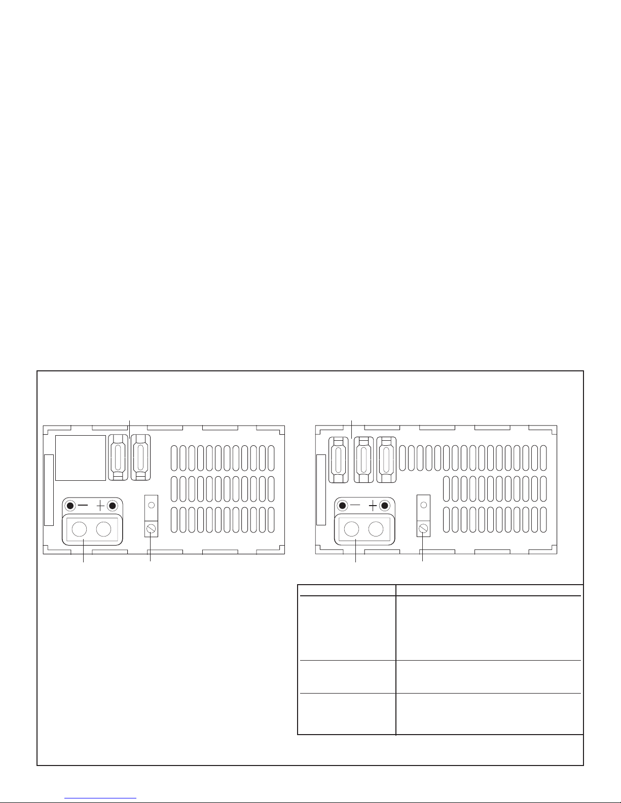
MODELS: APC 32, 45 & 55 MODELS: APC 75
Reverse Battery Protection Fuses
Serial # Code Date
Output Terminals
Before replacing converter perform the following
checks:
1. Disconnect the AC power from the coach.
2. Disconnect the wire from the “Positive Output
Terminal”.
3. Re-connect the AC power.
4. Using the voltmeter read the DC voltage at the
terminals on the converter.
• If the reading is greater than 13.4 VDC, but less
than 13.8 VDC the converter is operating properly.
Earth Ground/Chassis Lug
Reverse Battery Protection Fuses
Serial # Code Date
Output Terminals
PROBLEM SOLUTION
No 12 VDC Output • 120 VAC not connected to coach.
Converter cycles • Fan air flow inadequate.
on and off • Internal converter failure.
Low Output • Load excessive for rating of converter.
Earth Ground/Chassis Lug
• Converter circuit breaker in OFF position.
• Reverse battery fuses blown.
• Internal converter failure.
• Shorted output.
• Battery has bad cells.
• Internal converter failure.
2
 Loading...