

Page 1
2
QUICK GUIDE
VP DOME NETWORK CAMERA
Please read this manual thoroughly before use and keep it handy for future reference.
Page 2
3
WARNING
CAUTION
RISK OF ELECTRIC SHOCK
DO NOT OPEN
REFER SERVICING TO QUALIFIED SERVICE PERSONNEL
TO REDUCE THE RISK OF FIRE OR ELECTRIC SHOCK, DO NOT EXPOSE THIS PRODUCT TO RAIN OR MOISTURE. DO NOT INSERT ANY
METALLIC OBJECT THROUGH THE VENTILATION GRILLS OR OTHER
OPENNINGS ON THE EQUIPMENT.
CAUTION
WARNING: TO REDUCE THE RISK OF ELECTRIC SHOCK,
DO NOT REMOVE COVER (OR BACK).
NO USER-SERVICABLE PARTS INSIDE.
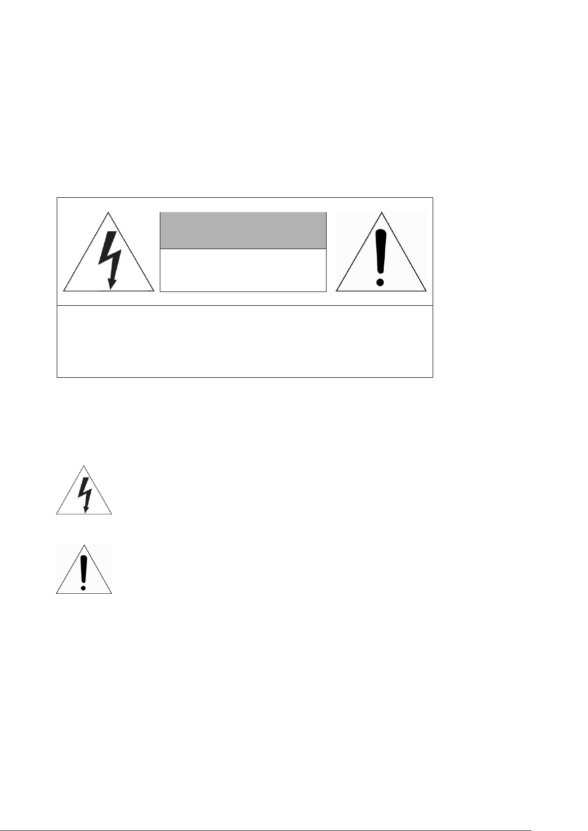
EXPLANATION OF GRAPHICAL SYMBOLS
The lightning flash with arrowhead symbol, within an equilateral triangle, is intended to alert the user to the presence of dangerous voltage within the products
enclosure that may be of sufficient magnitude to constitute a risk of electric shock
to persons.
The exclamation point within an equilateral triangle is intended to alert the user
to the presence of important operating and maintenance (servicing) instructions
in the literature accompanying the product.
Page 3

4
FCC COMPLIANCE STATEMENT
This device complies with Part 15 of the FCC Rules. Operation is subject
to the following two conditions: (1) this device may not cause harmful interference, and (2) this device must accept any interference received, including
interference that may cause undesired operation.
FCC INFORMATION: This equipment has been tested and found to
comply with the limits for a Class A digital device, pursuant to Part 15 of
the FCC Rules. These limits are designed to provide reasonable protection
against harmful interference when the equipment is operated in a commercial environment. This equipment generates, uses, and can radiate radio
frequency energy and, if not installed and used in accordance with the instruction manual, may cause harmful interference to radio communications.
Operation of this equipment in a residential area is likely to cause harmful interference in which case the user will be required to correct the interference
at his own expense.
CAUTION: Changes or modifications not expressly approved by the party
responsible for compliance could void the user’s authority to operate the
equipment.
This Class A digital apparatus complies with Canadian ICES-003.
Cet appareil nume
`
rique de la classe A est conforme a
´
la norme NMB-003 du
Canada.
WARNING
This is a Class A product. In a domestic environment this product may cause
radio interference in which case the user may be required to take adequate
measures.
CAUTION
RISK OF EXPLOSION IF BATTERY IS REPLACED BY AN INCORRECT TYPE.
DISPOSE OF USED BATTERIES ACCORDING TO THE INSTRUCTIONS.
CE COMPLIANCE STATEMENT
Page 4

5
IMPORTANT SAFETY INSTRUCTIONS
1. Read these instructions.
2. Keep these instructions.
3. Heed all warnings.
4. Follow all instructions.
5. Do not use this apparatus near water.
6. Clean only with dry cloth.
7. Do not block any ventilation openings. Install in accordance with the manufacturer’s instructions.
8. Do not install near any heat sources such as radiators, heat registers, stoves, or other apparatus
(including amplifiers) that produce heat.
9. Do not defeat the safety purpose of the polarized or grounding-type plug. A polarized plug has two
blades with one wider than the other. A grounding type plug has two blades and a third grounding
prong. The wide blade or the third prong is provided for your safety. If the provided plug does not fit
into your outlet, consult an electrician for replacement of the obsolete outlet.
10. Protect the power cord from being walked on or pinched particularly at plugs, convenience
receptacles, and the point where they exit from the apparatus.
11. Only use attachments/accessories specified by the manufacturer.
12. Use only with the cart, stand, tripod, bracket, or table specified by the
manufacturer, or sold with the apparatus. When a cart is used, use caution when
moving the cart/apparatus combination to avoid injury from tip-over.
13. Unplug this apparatus during lightning storms or when unused for long periods of
time.
14. Refer all servicing to qualified service personnel. Servicing is required when the apparatus has
been damaged in any way, such as power-supply cord or plug is damaged, liquid has been spilled
or objects have fallen into the apparatus, the apparatus has been exposed to rain or moisture, does
not operate normally, or has been dropped.
15. CAUTION : These servicing instructions are for use by qualified service personnel only. To
reduce the risk of electric shock do not perform any servicing other than that contained in
the operating instructions unless you are qualified to do so.
16. ITE is to be connected only to PoE networks without routing to the outside plant.
17. This product is intended to be supplied by a Listed Power Supply Unit marked “Class 2” or
“LPS” and rated from 12 Vdc, 710 mA.
18. The wired LAN hub providing power over the Ethernet (PoE) in accordance with IEEE 802-3af
shall be a UL Listed device with the output evaluated as a Limited Power Source as defined
in UL60950-1.
19. Unit is intended for installation in a Network Environment 0 as defined in IEC TR 62102. As
such, associated Ethernet wiring shall be limited to inside the building.
20. CAUTION : Risk of Explosion if Battery is replaced by an Incorrect Type. Dispose of Used
Batteries According to the Instructions.
ATTENTION : II y a danger d’explosion s’il y a remplacement incorrect de la batterie.
Remplacer uniquement avec une batterie du même type ou d’un type équivalent
recommandé par le constructeur. Mettre au rebut les batteries usagées conformément aux
instructions du fabricant.
Page 5

6
1 Introduction
The network camera supports the network service for a sensor image with progressive scan, which
can be monitored on a real-time screen regardless of distances and locations. By using its
dedicated program, many users are able to have an access to the network camera at once or a
single user can monitor various network cameras at the same time. It also enables users to play,
store and retrieve a monitoring image by using a PC. All the settings and real-time monitoring
screens are also provided through an access to the web.
The network camera is fully featured for security surveillance and remote monitoring needs. It is
based on the DSP compression chip, and makes it available on the network as real-time, full frame
rate Motion JPEG, H.264 and H.265 video streams.
The alarm input and alarm output can be used to connect various third party devices, such as,
door sensors and alarm bells.
1.1
This system comes with the following components;
Components
Network Camera 1
Installation Guide/CD 1
Template Sheet 1
Accessory Kit 1
Note 1. Check your package to make sure that you received the complete system, including all
components listed above.
Note 2. Adapter for DC 12V is not supplied.
Page 6

7
2 Installation
NO
Item
Description
1 RJ-45
Ethernet, RJ-45 port compatible
with 10/100Mbps PoE Modular Jack
2
DC Jack
Main Power, DC Jack, DC12V
3
AI: Alarm In
Alarm input and output, 3pin terminal
G: GND
AO: Alarm Out
4
MIC: Audio In
Audio line input, 2pin terminal
G: GND
5
SPK: Audio Out
Audio line output, 2pin terminal
G: GND
For the operation of the network camera, it is necessary to connect a network cable for data
transmission, power connection from power adapter. Depending on operation methods, it is
possible to connect an alarm cable additionally. For its fixation on different locations, please
consult with an installer.
2.1
Overview
•
Dimension
Dimensions Unit: mm
•
Extension Cable
Page 7

8
•
Installing & Adjusting Camera
Carefully remove the contents from the box.
1)
Loosen the four torx screws located the front of the housing leaving the screws intact in the
front portion.
2)
Make mounting holes and cable hole in the place(ceiling or wall) to which this dome.
Camera is installed using the template sheet.
Do not continue to turn the camera in same direction.
The cable connector can be detached.
Page 8

9
2.2
Remove the cap at bottom of the camera to insert the SD memory card.
Connect a standard RJ-45 cable to the network port of the network camera. Generally a cross-over
cable is used for directly connection to PC, while a direct cable is used for connection to a hub. You
can also use a router featuring PoE (Power over Ethernet) to supply power to the camera.
Connection
•
Micro SD memory slot on the Bottom Board
•
Connecting to the RJ-45
•
Connecting Alarms
AI(Alarm In): You can use external devices to signal the network camera to react on
events. Mechanical or electrical switches can be wired to the AI (Alarm In) and G (Ground)
connectors.
G(Ground): Connect the ground side of the alarm input and/or alarm output to the G (Ground)
connector.
AO(Alarm Out): The network camera can activate external devices such as buzzers or lights.
Connect the device to the AO (Alarm Out) and G (Ground) connectors.
•
Connecting the Power
Connect the power of 12VDC for the network camera. Connect the positive(+) pole to the ‘+’ position
and the negative (-) pole to the ‘-’ position for the DC power.
–
Be careful not to reverse the polarity when connecting the power cable.
–
A router featuring PoE (Power over Ethernet) can also be used to supply power to the
camera.
–
For the power specifications, refer to the appendix, product specification.
–
If PoE and 12 VDC are both applied, the camera will be supplied with power from PoE.
•
Connecting Audio
Connect speaker to audio line output and external Mic to audio input line.
•
Connecting Test Monitor Out(CVBS)
Connect 3pin test video cable(Optional) to check test video.
Page 9

10
2.3
Resetting to the factory default settings
To reset the network camera to the original factory settings, go to the Setup > System >
Maintenance web page (described in “System > Maintenance” of User Manual) or use the Reset
button on the network camera inside the bottom cap.
•
Using the Reset button:
Follow the instructions below to reset the network camera to the factory default settings using the
Reset button.
1)
Switch off the network camera by disconnecting the power adapter.
2)
Open the top cap.
3)
Press and hold the Reset button with a straightened paperclip while reconnecting the
power.
4)
Keep the Reset button pressed about 5 or more seconds.
5)
Release the Reset button.
6)
The network camera resets to factory defaults and restarts after completing the factory reset.
7)
Close the bottom cap tightly to ensure waterproof.
CAUTION: When performing a Factory Reset, you will lose any settings that have been
saved. (Default IP 192.168.30.220)
Page 10

11
2.4
The camera supports the operation through the network. When a camera is first connected to the
network, it is necessary to allocate an IP address to the device with the “SmartManager” utility on
the CD. (Default IP 192.168.30.220)
1)
2)
window will display, and after a short while any network devices connected to the network will be
displayed in the list.
3)
as below.
Network Connection & IP assignment
Connect the network camera/device to the network and power up.
Start SmartManager utility (Start > All programs > SmartManager > SmartManager). The main
Select the camera on the list and click right button of the mouse. You can see the pop-up menu
4)
Select Assign IP Address. The Assign IP window will display. Enter the required IP address.
NOTE: For more information, refer to the SmartManager User Manual.
Page 11

VP DOME NETWORK CAMERA
5030xxxxA
 Loading...