

ATV NVR8P, NVR16P Instruction Manual

NVR8P / NVR16P (PoE)
INSTRUCTION MANUAL
Model : NVR8P / NVR16P
8/16 Channel Network
Video Recorder
Please read this manual thoroughly before us e, and keep it handy for future reference.
WARNING
Should any liquid or solid object fall into the
Do not install the unit in an extremely hot or
TO REDUCE THE RISK OF FIRE OR ELECTRIC SHOCK, DO NOT EXPOSE THIS PROCUCT TO RAIN OR MOISTURE. DO NOT INSERT ANY METALLIC OBJECT THROUGH THE VENTILATION GRILLS OR OTHER OPENNINGS ON THE EQUIPMENT.
CAUTION
EXPLANATION OF GRAPHICAL SYMBOLS
The lightning flash with arrowhead symbol, within an equilateral triangle, is intended to alert
the user to the presence of uninsulated "dangerous voltage" within the product’s enclosure
that may be of sufficient magnitude t o constitute a risk of electric shock.
The exclamation point within an equilateral triangle is intended to alert the user to the
presence of important operating and maintenance (servicing) instructions in the literature
accompanying the appliance.
PRECAUTIONS
Safety -------------------------------------- Installation -------------------------------
cabinet, unplug the unit and have it checked by
the qualified personnel before operating it any
further.
Unplug the unit from the wall outlet if it is not
going to be used for several days or more. To
disconnect the cord, pull it out by the plug. Never
pull the cord itself.
Allow adequate air circulation to prevent internal
heat build-up. Do not place the unit on surfaces
(rugs, blankets, etc.) or near materials (curtains,
draperies) that may block the ventilation holes.
Height and vertical linearity controls located at the
rear panel are for special adjustments by qualified
personnel only.
humid place or in a place subject to excessive
dust, mechanical vibration.
The unit is not designed to be waterproof.
Exposure to rain or water may damage the unit.
Cleaning ---------------------------------
Clean the unit with a slightly damp soft cloth.
Use a mild household detergent. Never use
strong solvents such as thinner or benzene as
they might damage the finish of the unit.
Retain the original carton and packing materials
for safe transport of this unit in the future.
2

FCC COMPLIANCE STATEMENT
COMPLY WITH THE LIMITS FOR A CLASS A DIGITAL DEVICE, PURSUANT TO PART 15 OF
AGAINST HARMFUL INTERFERENCE WHEN THE EQUIPMENT IS OPERATED IN A
COMMERCIAL ENVIRONMENT. THIS EQUIPMENT GENERATES, USES, AND CAN RADIATE
RADIO FREQUENCY ENERGY AND IF NOT INSTALLED AND USED IN ACCORDANCE WITH
UL INTERFERENCE TO RADIO
CHANGES OR MODIFICATIONS NOT EXPRESSLY APPROVED BY THE PARTY
This is a Class A product. In a domestic environment this product may cause radio
INFORMATION TO THE USER: THIS EQUIPMENT HAS BEEN TESTED AND FOUND TO
THE FCC RULES. THESE LIMITS ARE DESIGNED TO PROVIDE REASONABLE PROTECTION
THE INSTRUCTION MANUAL, MAY CAUSE HARMF
COMMUNICATIONS.
CAUTION:
RESPONSIBLE FOR COMPLIANCE COULD VOID THE USER'S AUTHORITY TO OPERATE THE
EQUIPMENT.
THIS CLASS A DIGITAL APPARATUS COMPLIES WITH CANADIAN ICES-003.
CET APPAREIL NUMÉRIQUE DE LA CLASSE A EST CONFORME À LA NOR ME NMB-003 DU
CANADA.
CE COMPLIANCE STATEMENT
WARNING:
interference in which case the user may be required t o take adequate measures.
3

IMPORTANT SAFETY INSTRUCTIONS
1. Read these instructions.
2. Keep these instructions.
3. Heed all warnings.
4. Follow all instructions.
5. Do not use this apparatus near water.
6. Clean only with dry cloth.
7. Do not block any ventilation openings. Install in accordance with the manufacturer’s
instructions.
8. Do not install near any heat sources such as radiators, heat registers, stoves, or other
apparatus (including amplifiers) that produce heat.
9. Do not defeat the safety purpose of the polari zed or grounding-type plug. A polarized plug has
two blades with one wider than the other. A grounding type plug has two blades and a third
grounding prong. The wide blade or the third prong is provided for your safety. If the provided
plug does not fit into your outlet, consult an electrician for replacement of the obsolete outlet.
10. Protect the power cord from being walked on or pinched particularly at plugs, convenience
receptacles, and the point where they exit from the apparatus.
11. Only use attachments/acc essories specified by the manufacturer.
12. Use only with the cart, stand, tripod, bracket, or table specified by the
manufacturer, or sold with the apparatus. When a cart is used, use
caution when moving the cart/apparatus combination to avoid injury
from tip-over.
13. Unplug this apparatus during lightning storms or when unused for long
periods of time.
14. Refer all servicing to qualified service personnel. Servicing is required
when the apparatus has been damaged in any way, such as powersupply cord or plug is damaged, liquid has been moisture, does not
operate normally, or has been dropped.
15. CAUTION – THESE SERVICING INSTRUCTIO NS ARE FOR USE BY QUALIFIED
SERVICE PERSONNEL ONLY. TO REDUCE THE RISK O F E LECTRIC SHOCK DO
NOT PERFORM ANY SERVICING OTHER THAN THAT CONTAINED IN THE
OPERA TING INSTRUCTIONS UNLESS YOU ARE QUALIFIED TO DO SO.
16. Use satisfying clause 2.5 of IEC60950-1/UL60950-1 or Certified/Listed Class 2
power source only.
17. ITE is to be connected only to PoE networks without rout i ng to the outside plant.
4

Contents
Chapter 1. Introduction -------------------------------------------------------------------------------------------------- 10
1.1. Description ------------------------------------------------------------------------------------------------------------- 10
1.2. Components ------------------------------------------------------------------------------------------------------------ 10
1.3. Key Features ----------------------------------------------------------------------------------------------------------- 10
1.4. Basic Security System Configuration ---------------------------------------------------------------------------- 12
1.5. Front Panel View and Keypads ------------------------------------------------------------------------------------ 13
1.6. Rear Panel View ------------------------------------------------------------------------------------------------------- 14
1.7. IR Remote Control ---------------------------------------------------------------------------------------------------- 15
Chapter 2. Installation --------------------------------------------------------------------------------------------------- 16
2.1. HDD Installation ------------------------------------------------------------------------------------------------------- 16
2.2. Network Connection Setup ---------------------------------------------------------------------------------------- 17
2.2.1. Using a Static IP Address -------------------------------------------------------------------------------------- 17
2.2.2. Using a Dynamic IP Address -------------------------------------------------------------------------------- 17
2.2.3. Router Configuration ------------------------------------------------------------------------------------------ 18
2.2.3.1. WAN Setting ----------------------------------------------------------------------------------------------------- 18
2.2.3.2. DHCP & IP Address Setting --------------------------------------------------------------------------------- 18
2.2.3.3. Virtual Server Setting ---------------------------------------------------------------------------------------- 19
STARTING THE SYSTEM ---------------------------------------------------------------------------------------------- 20
LIVE MENU DESCRIPTION ------------------------------------------------------------------------------------------- 21
SYSTEM INFORMATION ----------------------------------------------------------------------------------------------- 22
LIVE MENU NAVIGATING USING THE MOUSE ----------------------------------------------------------------- 23
LIVE MENU NAVIGATING USE THE REMOTE CONT ROL --------------------------------------------------- 24
Chapter 3. Main Menu Setup ----------------------------------------------------------------------------------------- 25
3.1. Video/Audio Setup ---------------------------------------------------------------------------------------------------- 26
3.1.1. Camera (Channel) Name and Display ------------------------------------------------------------------------ 26
3.1.2. IP Camera Registration ------------------------------------------------------------------------------------------- 28
3.1.3. IP Camera Setup --------------------------------------------------------------------------------------------------- 31
3.1.4. Monitor ------------------------------------------------------------------------------------------------------------ 34
3.1.5. Sequence/Events Display ----------------------------------------------------------------------------------- 35
3.1.6. OSD/Display Position ------------------------------------------------------------------------------------------ 36
3.1.7. Screen Mode ---------------------------------------------------------------------------------------------------- 37
3.2. Record Setup -------------------------------------------------------------------------------------------------------- 38
3.2.1. Record Policy ------------------------------------------------------------------------------------------------------- 38
5

3.2.2. RECORDING SCHEDULE SETUP --------------------------------------------------------------------------- 39
3.2.3. Holiday ------------------------------------------------------------------------------------------------------------ 40
3.2.4. Event Record Duration -------------------------------------------------------------------------------------------- 41
3.2.5. Record Option ---------------------------------------------------------------------------------------------------- 41
3.3. Device Setup ----------------------------------------------------------------------------------------------------------- 42
3.3.1. Storage ------------------------------------------------------------------------------------------------------------- 42
3.3.2. Sensor/Video Loss Detection Setup ----------------------------------------------------------------------- 44
3.3.3. Alarm Schedule ---------------------------------------------------------------------------------------------------- 45
3.3.4. PTZ ------------------------------------------------------------------------------------------------------------------- 46
3.3.5. System Controller/Printer Device ------------------------------------------------------------------------------- 46
3.3.6. POS/ATM Device ------------------------------------------------------------------------------------------------ 47
3.3.7. Video Analysis ------------------------------------------------------------------------------------------------- 48
3.4. System Setup --------------------------------------------------------------------------------------------------------- 49
3.4.1. Date/Time ------------------------------------------------------------------------------------------------------------ 49
3.4.2. Signal/Language/Device N ame -------------------------------------------------------------------------------- 50
3.4.3. Config -------------------------------------------------------------------------------------------------------------- 51
3.4.4. Log Information ------------------------------------------------------------------------------------------------- 51
3.4.5. Authorization Management ---------------------------------------------------------------------------------- 52
3.4.5.1. ADMIN ---------------------------------------------------------------------------------------------------------- 52
3.4.5.2. GROUP ------------------------------------------------------------------------------------------------------------- 53
3.4.5.3. USER ------------------------------------------------------------------------------------------------------------- 54
3.4.5.4. SETUP -------------------------------------------------------------------------------------------------------------- 55
3.5. Network Setup --------------------------------------------------------------------------------------------------------- 56
3.5.1. Connection -------------------------------------------------------------------------------------------------------- 56
3.5.2. Port/Connection Test (Ping) -------------------------------------------------------------------------------------- 58
3.5.3 ID & Password ---------------------------------------------------------------------------------------------------- 59
3.5.4. DDNS --------------------------------------------------------------------------------------------------------------- 60
3.5.5. NAT Traversal ---------------------------------------------------------------------------------------------------- 61
3.5.6. Email / SNS (Social Network Service) ----------------------------------------------------------------------- 62
3.5.6.1. Email / SN S: SMTP --------------------------------------------------------------------------------------------- 62
3.5.6.2. Email / SNS: Event ------------------------------------------------------------------------------------------- 63
3.5.6.3. Email / SNS: Schedule ---------------------------------------------------------------------------------------- 64
3.5.6.4. Email / SNS: Recipient ---------------------------------------------------------------------------------------- 65
3.6. Backup Setup ---------------------------------------------------------------------------------------------------------- 66
Chapter 4. Search Menu Setup --------------------------------------------------------------------------------------- 67
4.1. Time Search --------------------------------------------------------------------------------------------------------- 67
4.2. Event Search -------------------------------------------------------------------------------------------------------- 69
4.3. Protect ---------------------------------------------------------------------------------------------------------------- 69
6

4.4. Capture --------------------------------------------------------------------------------------------------------------- 70
4.5. POS/ATM Device -------------------------------------------------------------------------------------------------- 70
4.6. Video Analysis --------------------------------------------------------------------------------------------------------- 71
Chapter 5. General Operation ----------------------------------------------------------------------------------------- 72
5.1. Mouse Menu -------------------------------------------------------------------------------------------------------- 72
5.1.1 Screen Mode ------------------------------------------------------------------------------------------------------ 72
4-Split --------------------------------------------------------------------------------------------------------------- 73
PIP ------------------------------------------------------------------------------------------------------------------- 73
Auto Sequence ------------------------------------------------------------------------------------------------- 73
5.1.2. Audio On/Off -------------------------------------------------------------------------------------------------- 74
5.1.3. Zoom ------------------------------------------------------------------------------------------------------------------- 74
5.1.4. Freeze --------------------------------------------------------------------------------------------------------- 75
5.1.5. Stop Alarm ---------------------------------------------------------------------------------------------------- 75
5.1.6. Record Stop -------------------------------------------------------------------------------------------------- 75
5.1.7. Play ------------------------------------------------------------------------------------------------------------- 76
5.1.8. Search (See Chapter 4) ----------------------------------------------------------------------------------- 76
5.1.9. Backup --------------------------------------------------------------------------------------------------------- 76
5.1.10. Main Menus (See Chapter 3) --------------------------------------------------------------------------- 77
5.1.11. Information ------------------------------------------------------------------------------------------------------- 77
5.1.12. IP Cam Info ------------------------------------------------------------------------------------------------------ 77
5.1.13. EZ (Easy) Setup -------------------------------------------------------------------------------------------------- 78
5.1.14. Hide/Show Launcher --------------------------------------------------------------------------------------------- 78
5.1.15. Log Out ------------------------------------------------------------------------------------------------------------- 79
5.2. Live Launcher ------------------------------------------------------------------------------------------------------- 79
5.2.1. Control Button Description --------------------------------------------------------------------------------------- 80
5.3. Playback Launcher ------------------------------------------------------------------------------------------------ 81
5.3.1. Control Buttons ------------------------------------------------------------------------------------------------------ 82
5.3.2. Playback & Trick Mode ---------------------------------------------------------------------------------------- 83
5.4. PTZ Control --------------------------------------------------------------------------------------------------------- 84
Chapter 6. Protect Video/Audio Files ------------------------------------------------------------------------------- 87
6.1. Protect Registration ----------------------------------------------------------------------------------------------- 87
6.2. Playback and Remove Protected File ------------------------------------------------------------------------ 87
6.3. Protected File Backup ----------------------------------------------------------------------------------------------- 88
Chapter 7. Capture Video Still Image ------------------------------------------------------------------------------- 89
7.1. Still Image capture------------------------------------------------------------------------------------------------- 89
7.2. Retrieve and view Captured Images -------------------------------------------------------------------------- 89
7

7.3. Remove Captured Images -------------------------------------------------------------------------------------- 90
7.4. Backup Captured Image ----------------------------------------------------------------------------------------- 91
Chapter 8. Web Viewer – Connect to NVR via Internet Explorer ------------------------------------------ 92
8.1. System Requirement ---------------------------------------------------------------------------------------------- 92
8.1.1. Network Environment ---------------------------------------------------------------------------------------------- 92
8.2. Web Viewer-Getting Started ------------------------------------------------------------------------------------- 92
8.2.1. Connect NVR via Web Browser using Direct IP ------------------------------------------------------------ 92
8.2.2 General Web Viewer Operation ---------------------------------------------------------------------------------- 93
8.2.3. Calendar and Time Search --------------------------------------------------------------------------------------- 94
8.2.4. PTZ Control ------------------------------------------------------------------------------------------------------- 95
8.2.5. Connect to NVR via Web Browser using URL -------------------------------------------------------------- 96
Chapter 9. Web Viewer Setup/W eb Configuration -------------------------------------------------------------- 97
9.1. Web Configuration ---------------------------------------------------------------------------------------------------- 97
9.1.1. Video/Audio ---------------------------------------------------------------------------------------------------------- 97
9.1.1.1.Camera ------------------------------------------------------------------------------------------------------------ 97
9.1.1.2. IP Registration ------------------------------------------------------------------------------------------------- 97
9.1.1.3. IP Camera Setup --------------------------------------------------------------------------------------------- 98
9.1.1.4. Monitor ------------------------------------------------------------------------------------------------------------ 98
9.1.1.5. Sequence/Event Display ----------------------------------------------------------------------------------- 98
9.1.1.6. OSD/Display Position ----------------------------------------------------------------------------------------- 99
9.1.2. Record --------------------------------------------------------------------------------------------------------------- 99
9.1.2.1. Policy -------------------------------------------------------------------------------------------------------------- 99
9.1.2.2. Schedule ----------------------------------------------------------------------------------------------------------99
9.1.2.3. Holiday------------------------------------------------------------------------------------------------------------- 100
9.1.2.4. Event Record Duration --------------------------------------------------------------------------------------- 100
9.1.2.5. Record Option --------------------------------------------------------------------------------------------------- 100
9.1.3. Device --------------------------------------------------------------------------------------------------------------- 101
9.1.3.1 Sensor Detection ---------------------------------------------------------------------------------------------- 101
9.1.3.2. Video Loss Detection ---------------------------------------------------------------------------------------- 101
9.1.3.3. Alarm Schedule ----------------------------------------------------------------------------------------------- 101
9.1.3.4 PTZ --------------------------------------------------------------------------------------------------------------- 102
9.1.3.5. System Controller ---------------------------------------------------------------------------------------------- 102
9.1.3.6. Storage ----------------------------------------------------------------------------------------------------------- 102
9.1.4. System --------------------------------------------------------------------------------------------------------------- 103
9.1.4.1. Date/Time -------------------------------------------------------------------------------------------------------- 103
9.1.4.2. Time Synchronization Setup -------------------------------------------------------------------------------- 103
9.1.4.3. Signal/Language ---------------------------------------------------------------------------------------------- 103
8

9.1.4.4. System Information ------------------------------------------------------------------------------------------- 104
9.1.4.5. Authorization Management --------------------------------------------------------------------------------- 104
9.1.5. Network -------------------------------------------------------------------------------------------------------------- 106
9.1.5.1. Connection ------------------------------------------------------------------------------------------------------- 106
9.1.5.2. Port ----------------------------------------------------------------------------------------------------------------- 106
9.1.5.3. DDNS ---------------------------------------------------------------------------------------------------------- 106
9.1.5.4. Email/SNS ----------------------------------------------------------------------------------------------------- 107
Appendix
Product Specifications ------------------------------------------------------------------------------------------------ 110
System Keyboard ------------------------------------------------------------------------------------------------------ 112
POS Configuration ------------------------------------------------------------------------------------------------- 116
ATM Configuration ---------------------------------------------------------------------------------------------------- 118
Network Troubleshooting--------------------------------------------------------------------------------------------- 119
Terms/Icon Glossary -------------------------------------------------------------------------------------------------- 122
NVR Icon Reference -------------------------------------------------------------------------------------------------- 123
How to download Windows Media Player 10+ or V LC Media Player and play AVI files ------------- 124
Dashboard ----------------------------------------------------------------------------------------------------------------125
9

Chapter 1. Introduction
1.1. Description
This manual applies to the 8/16 channel networ k v i deo recorder. (model: NVR8P and NVR16P)
The network video recorders support up to 8/16 network cameras. The NVR can record high quality
Full HD images onto its maximum capacity of hard disk drives.
The network video recorder is extremely straightforward to install and setup, as it detects network
cameras and defines the parameters of each through a dedicated configuration wizard. You can start
monitoring instantly, as the images are automatical l y assigned to a layout menu.
Based on embedded Linux and high performance, the network NVRs are fully featured for secu rity
surveillance and remote monitoring needs.
1.2. Components
The system comes with the following components:
Network Video Recorder unit
IR Remote Control
DC Power Adapter
Power Cable
AAA Battery
HDD Brackets
Screw Packet
Installation CD including Client Software, Installation Guide and User Manual
Note: Check your package to make sure that y ou received the complete system, including all
components shown above.
1.3. Key Features
The NVR is the most competitive device developed for all industrial applications. In addition to its
sleek professional design, it is very reliable and cost effective. Most of all, its real time and crystal clea r
picture quality with small recording file size and powerful remote control function will become the
standard to which other security systems are judged. Also, its VCA (video content analysis) function
will offer you the advanced security envi ronment.
Major features include:
► 8/16 channels input for IP cameras by embedded 8/16port PoE switch
► Full HD Realtime recording of all channels
► Full HD (1920 x 1080P) display on HDMI and VGA
► PENTAPLEX: simultaneous Liv e, Recording, Playback, Backup, Network
► Extremely small recording file size using H.264 compression technology
► Adjustable recording frame rate, resolution and pi cture quality
► Video / Audio data backup via USB 2.0 or CMS
► Support Authentic Video Image Player
► High speed network transmission
► Dynamic / Static IP address support, Own Client (Titanium or CMS Software) support
► Remote recording, still image capturing and printing
10

► Multiple NVRs and multiple clients support for CMS application
► PTZ camera control by RS-485 and via network
► Independent color adjustment for each camera input and VGA output
► USB Mouse and IR remote control unit for user inte rf ace
► Self-diagnosis system and Hardware Watchdog : error checking and restoring functions
► Powerful event search function (Search by manual, schedule, motion, sensor, network or all)
► Pre-Alarm Recording for motions and sensors
► Protect Video/Audio files from HDD Overwrite
► Still im age capt uring and printing during live or playback
► System & Event Log files management
► Configuration data copy to other c hannels for easy setup
► Configuration file Export / Import for easy installation of multiple NVRs
► Control of minimum recording dates by channel
► Mobile (I-Phone, Android, Black Berry, Symbian and Windows mobile) phone support
► E-Map support
► Video Analysis support
Notice:
The information in this manual was current when published. The manufacturer reserves the
right to revise and improve its products. All specifications are therefore subject to change
without notice.
11
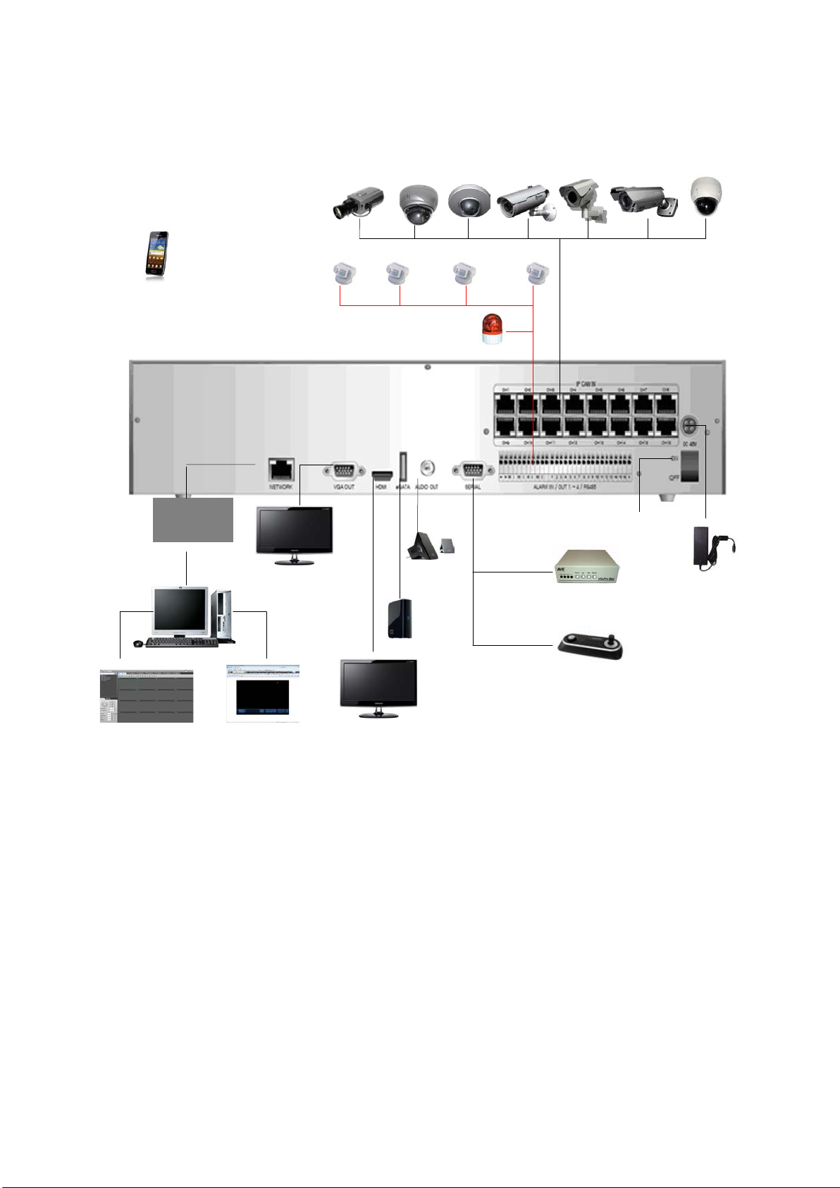
1.4. Basic Security System Configuration
LOCAL
INTERNET
Web Browser
WebViewer
Amplified
DC Power
Adapter
External
HDD
Keyboard-Controller
Alarm Out
• AC 125V 0.5A max
Sensor Inputs
• TTL Level Input
Smartphone
IP Cameras
PC
Client Software
NETWORK OR
• NC/NO Devices scalable
• NO Devices
• DC 30V 1A max
VGA Monitor
HDMI Monitor
Speaker
Power Switch
AVE VSI Pro Max
Note: The configuration example above is based on the 16Channel embedded PoE switch
models.
12

1.5. Front Panel View and Keypads
1
2
3
4
5
6
1. POWER LED: NVR power indicator.
2. REC LED: Recording indicator.
3. PLAYBACK LED: Playback mode indicator. A green light will be on when you play a recorded file
back.
4. NET LED: Network connection indicator. A green light will be on when the NVR is connected to the
network.
5. USB 2.0 Port: Connect USB mouse or USB memory device for file backup or firmware upgrade.
6. IR REMOTE CONTROL SENSOR: Receives all incoming signals from t he remote control.
13
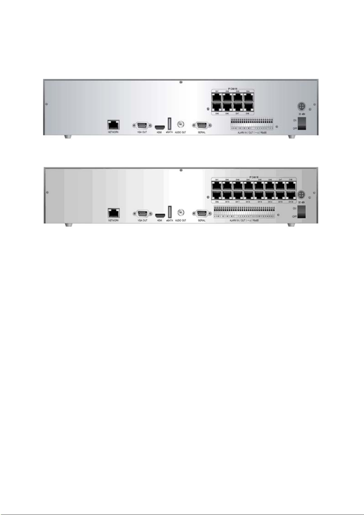
1.6. Rear Panel View
NVR8P
NVR16P
Note:
* Available Input/Output connectors and features are different from each model (part). Please
contact distributors to check the exact part number with your desired Input/Out connectors
and features. This manual describes all possible Input/Output connectors and features of this
series.
14

1.7. IR Remote Control
1. Audio: ON/ OFF function.
2. REC (Record): Start/stop manual recording.
3. Number Buttons: Select camera (channel) number.
4. ID SEL: Allows you to select ID setting.
5. ID: Displays current ID.
6. Info: It will display system information.
7. Print: Allows you to Print image either in Live or Playback Mode.
8. Navigate Buttons: ◀ Left ▲ Up ▶ Right ▼ Down :
9. Enter
: To select and save the menu and parameter change.
10. Menu: Enter or exit the menu.
11. Return: Directs you back to the previous menu. In Live Mode, this
button will log you out.
12. Mode: Change the display mode to different split screen.
13. Freeze: Freezes images. (Only in Live Mode).
14. Zoom: Zoom in/out the video when the channel is single display
mode.
15. Bookmark: It will list all the files that was bookmarked.
16. EZ Setup: You’ll be able to setup your system with simple pages.
17. K-Lock: Locks any keys from functioning.
18. Alarm: Turns the Alarm off.
19. Backup: Backups up desired data.
20. PTZ: Control PTZ camera(s) connected to your NVR.
21. Preset: A preset is a set of specific target points of a PTZ camera.
22. Tele: Zooms in on a specific area when using the PTZ function.
23. Wide: Zooms out of that specific area when using the PTZ
function.
24. Search: Go to recorded file search menu.
25. Pause
: Pause a video during playback mode.
26. Protect: You can protect recorded data from HDD overwriting.
27. Capture: You can capture video image either in Playback Mode or
Live Mode.
28. REW: Rewind (select speeds from 2x4x8x16x32x64 for faster
rewind).
29. ▶ Play: Play a recorded file.
30. ■ Stop: Stop playback.
31. FF: Fast forward (select speeds from 2x4x8x16x32x64).
ID Setting Instruction:
1) Press down ID SEL button for 3 seconds to start the ID Setting Mode
2) Input any 2 digits to set ID.
3) Once the 2 digits are selected, press enter.
* If no action is taken within the 20 second allowed time period, it will au tomatically exit you
from the ID Setting.
Installing batteries
1. Remove the battery cover by sliding in the direction of the arrow.
2. Insert two AAA batteries according to directions provided.
3. Replace the battery cover by sliding in the direction of the arrow.
15

Chapter 2. Installation
2.1. HDD Installation
Before Installation
We recommend setting the current time on your NVR before HDD Installation.
Please make sure that the power of NVR is switched off before starting installation.
Step 1. Make sur e the NVR power is switched OFF
Step 2. Open the top cover of N VR using a cross screw driver.
Step 3. Take out the HDD mounting plate from NVR.
Step 4. Place HDD(s) on the m ount i ng plate and mount it with screws.
Step 5. Replace the mounting plate into the NVR and fix it with screws.
Step 6. Attach the data and power cable to HDD(s) correctly.
Step 7. Replace the top cover of NV R and fix it with screws.
After HDD installation
Step 8. Turn the NVR power ON.
Step 9. NVR will detect HDD(s ) during the booting and will format HDD(s).
Step 10. After HDD formatting, NVR will be automatically rebooted and will be ready to work
with HDD(s).
16
2.2. Network Connection Setup
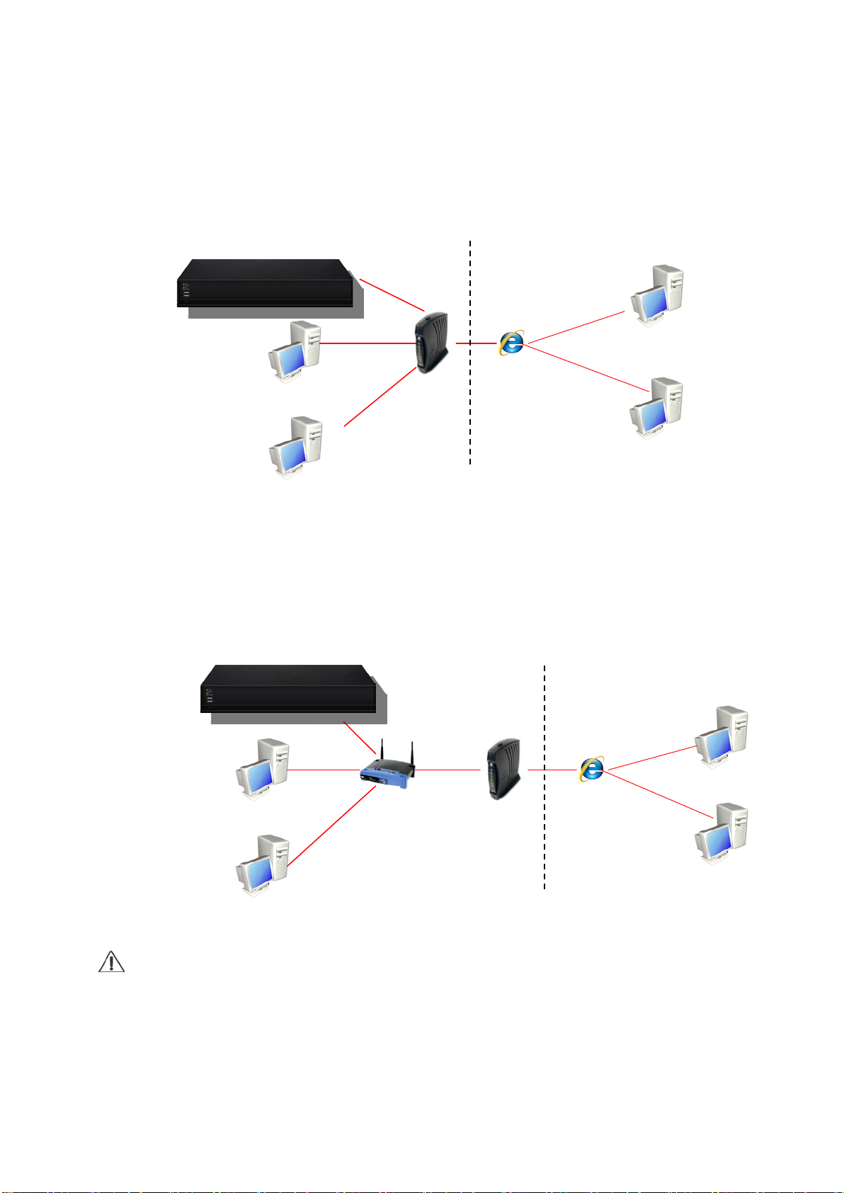
2.2.1 Using a Static IP Address
You can use the Static IP address, Subnet Mask and Gateway address provided by your ISP
(Internet Service Provider) for your NVR. The Gateway address is the IP address of your
broadband modem.
Internet
2.2.2 Using a Dynamic IP Address
You can use a router with your Dynamic IP broadband modem. In this case, you should set the
configuration of a router properly for network connection between NVR and Net/Web Viewer.
Please follow the instructions in next section t o conf i gure your router correctly.
Home/Office Network Internet
If your Broadband Modem does not support internal loop back (port forwarding) function
and you want to monitor NVR using a PC located in same Intranet, you should use Direct
IP instead of DDVRLS in the connection menu of NetViewer. If your PC is located outside
of Intranet, you can use both DDVRLS and Direct IP to connect to NVR even though your
Broadband Modem has limited features.
17
2.2.3. Router Configuration
If you have any problem with DHCP function or want to assign the private IP address, please
If your NVR is connected to the network through a rout er, you should configure router properly.
There are 3 steps as follows.
1. WAN Setting 2. DHCP Setting 3. Virtual Server Setting
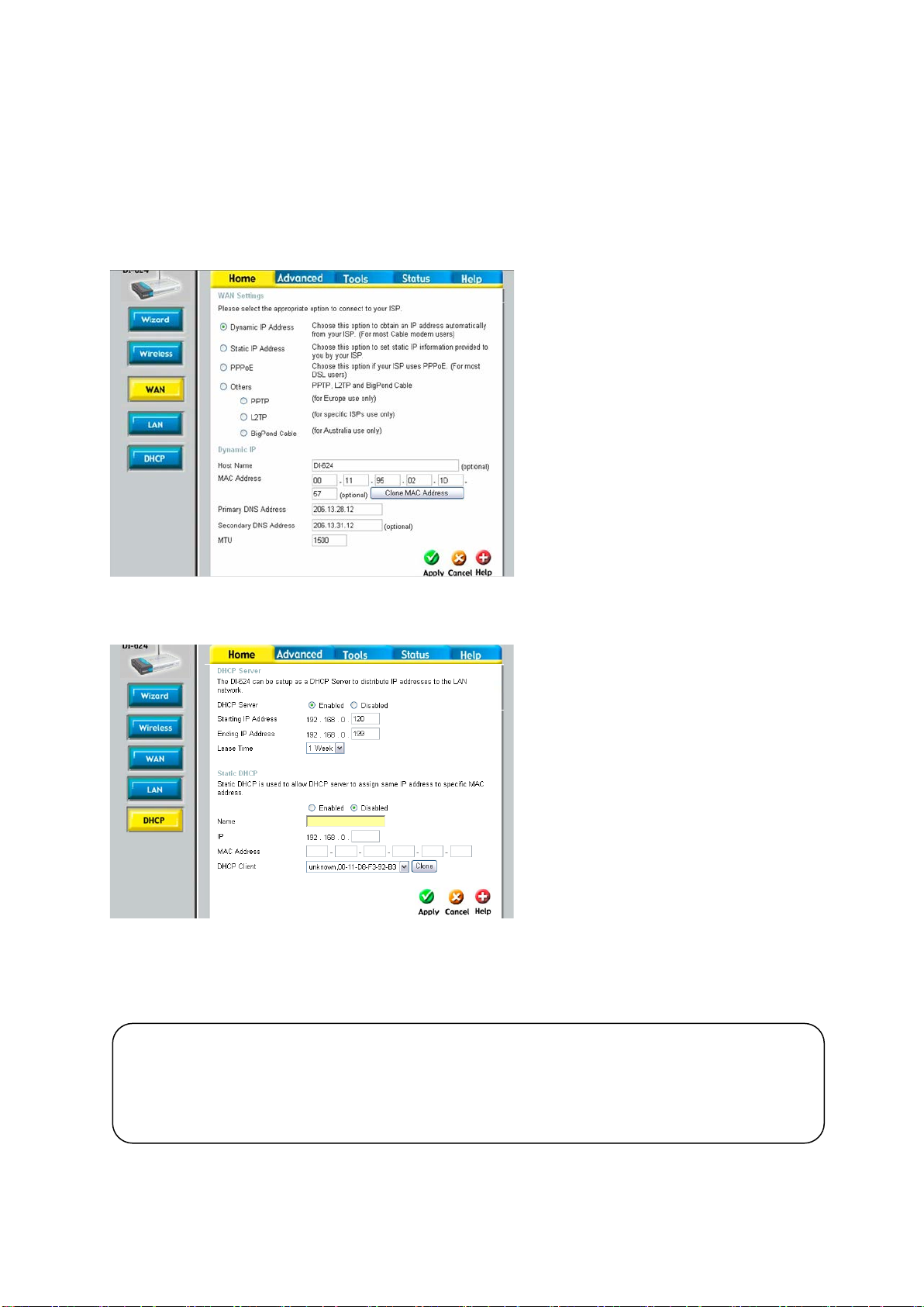
2.2.3.1. WAN Setting
When you connect to your Router, you
can find menu for WAN setting. Please
confirm the WAN setting. If you are using
DSL service, you should select PPPoE,
and you will be directed to a sub-menu to
type in DSL user name and password.
2.2.3.2. DHCP & IP Address Setting
To assign an unique private IP address to
NVR in your intranet environment
automatically, you can enable DHCP
option in the Network Setup menu of your
NVR and your Router. In this case, you
can skip the procedures described on
this page.
We recommend assigning IP address to
NVR manually to prevent unexpected
change of IP address.
*A router from D-Link is quoted as an example in this manual. The images of setup menu above may
not always match another router’s setup menu.
disable DHCP option in the Network Setup menu of your NVR and check the starting and ending
IP used by DHCP server of the Router. You can assign any private IP address to your NVR
even if it is out of the DHCP range, but the IP address should match with the one entered in
the Network Setup menu of your NVR.
18
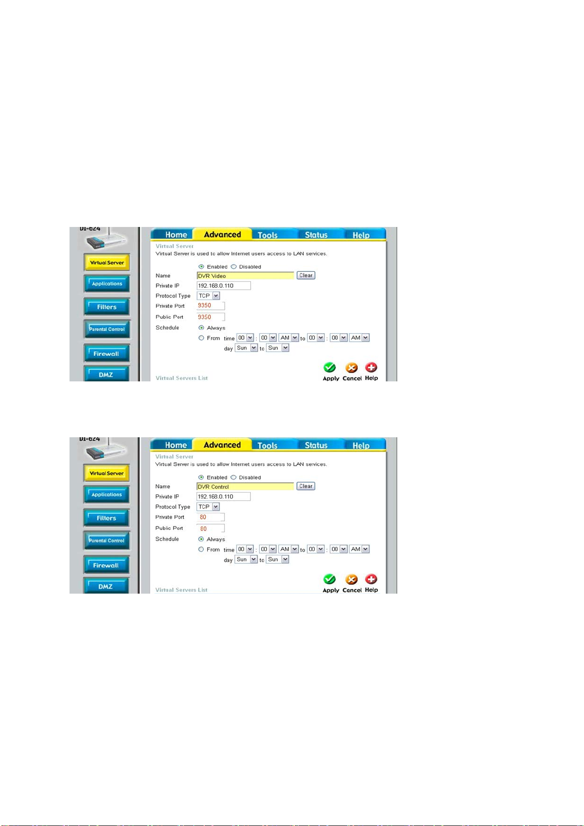
2.2.3.3. Virtual Server Setting
You should register your NVR as a virtual server. Please enter the information into IP
address field of the router (e.g. 192.168.0.110).
Protocol Type should be TCP. Private/Public Port numbers should be the same with the Port
numbers assigned in NVR. You can change port numbers in Network Setup menu to avoid conflict
with other network servers.
Your NVR uses 3 port numbers and the default Port numbers are 9350~1 and 80.
9350~1 are for controlling the video, audio and commands of Net Viewer, and 80 is for Web Viewer.
You need to register 3 port numbers into the router as network servers. Please make sure that your
router does not block those port numbers to/from the NVR with filter and firewall features.
19
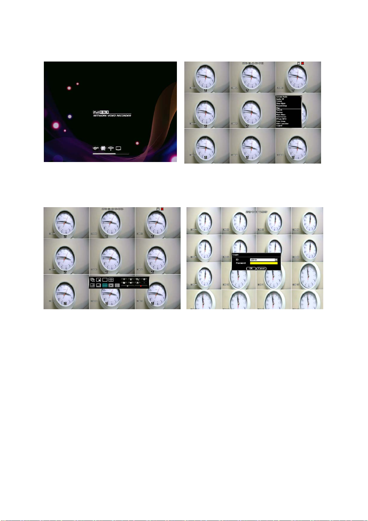
STARTING THE SYSTEM
When power is turned on, you will see the initializing screen which will diagnose your system therefore
it may take up to one minute to complete. If the unit does not completely initialize and stops short of
completion, there may be issues with the system. After initializing is complete, a live screen will appear.
To log in, right click any area on the screen and a live menu will appear. Click to any menu and it will
prompt you to login dialog.
Enter ID and Password by using the virtual keyboard and click OK. By default, the ID is set at “admin”
and the Password is set at “admin”
20
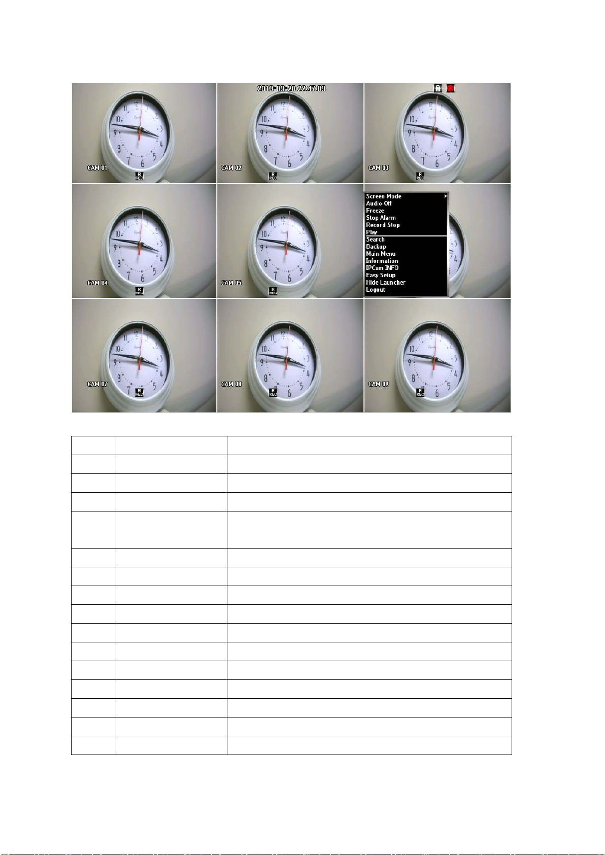
LIVE MENU DESCRIPTION
MENU DESCRIPTION
1 SCRE EN MODE Can select how you would like to view screen
2 AUDIO ON/OFF
Option to have the audio on or off
3 FREEZE Can freeze Playback or Live scene
Stops the alarm output and the event monitoring. Refer to
4 STOP ALARM
"Event Monitoring"
5 RECORD STOP Starts/stops the standard recording
6 PLAY Plays the search result (data).
7 SEARCH Can search for recorded data
8 BACKUP Can backup data via USB drive
9 MAIN MENU Access the main menu. Refer to the Using the NVR section
10 INFORMATION This menu will display system information
11 IP CAM INFO It will display you IP camera information
12 EZ SETUP (EASY) You’ll be setup your system with simple pages
13 SHUT DOWN Will allow you to completely shut down the unit
14 HIDE LAUNCHER Hides the launcher.
15 LOGOUT You can log out.
21
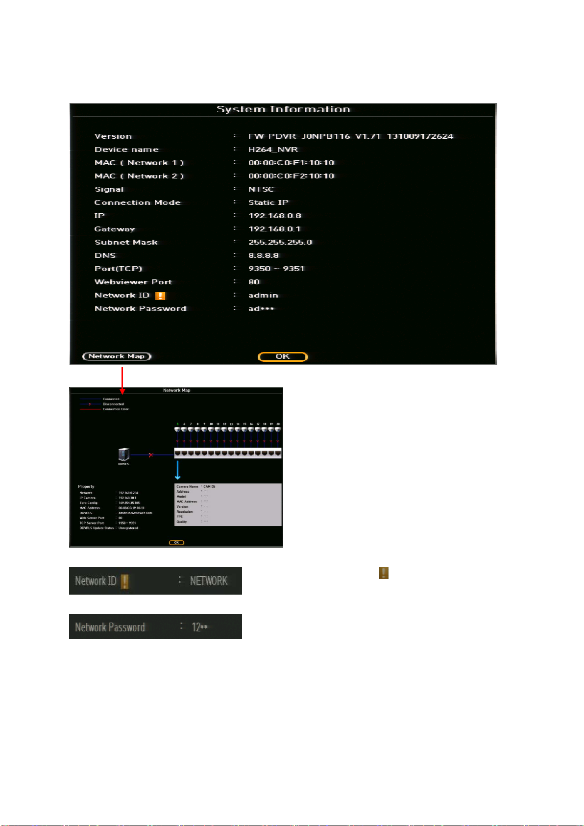
SYSTEM INFORMATIOIN
This menu will display overall system information
When there’s an exclamation , this indicates that the NVR
has not been registered in our DDVRLS server
Password will only show half of the registered password.
You can enter up to 8 characters max. If four characters are
used in the password, it will show as 12**, six characters will
show as 123*** and eight character, 1234****
Network Map: By clicking the Network Map button,
it will display a page with all your IP camera status.
If the IP camera is connected, then a blue line will
be shown. If the camera is disconnected, then a
blue line with a red X mark will be shown. If there is
a connection error, a solid red line will be shown.
By using you mouse, you can navigate to each IP
camera to see the camera information.
*Network Map feature is only available with PoE
NVRs
22

LIVE MENU NAVIGATING USING THE MOUSE
Navigating to the different channels by u sing the mouse.
By using the mouse, move the mouse to the far right in the middle of the screen and an arrow button
will appear on the screen (see picture above) to navigate to different channels. If you are viewing the
channels in a 4 split mode on a 16ch NVR and by clicking the arrow button, it will take you to the next
four channels. When viewing in a 9 split mode, then it will go to the next set of 9 channels.
For a 16 channel NVR, you can use this mouse navigation when viewing in a single CH (1CH), 4-split
screen and 9-split screen only. No other screen mode will allow you to use this function.
23
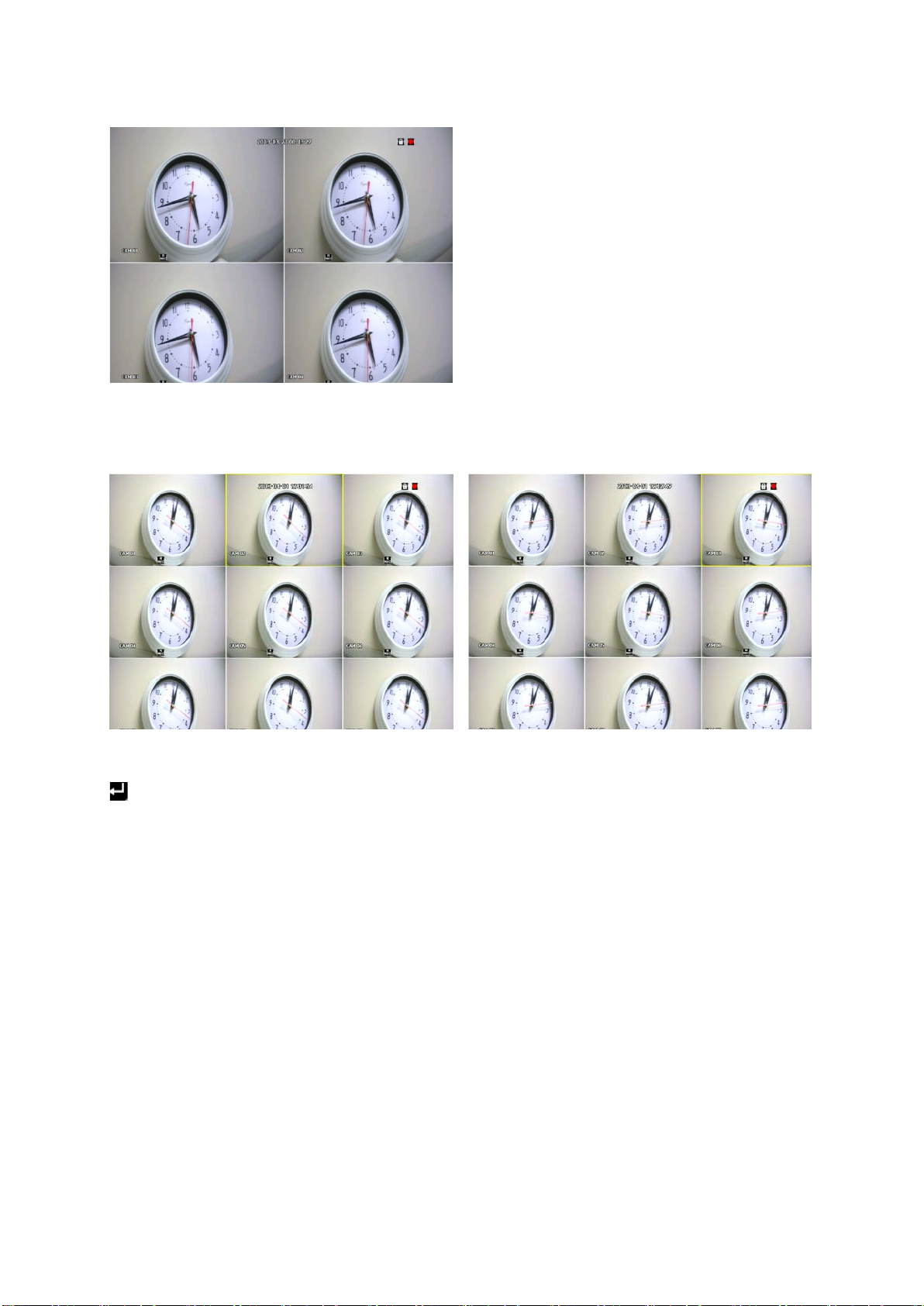
LIVE MENU NAVIGATING USE THE REMOTE CONTROL
When no channels are selected, you can use the remote control to navigate to another interval. In this
example, it is in a 4-split screen. By pressing the direction button on the remote control ▶, it will take
you to the next four channels.
If a channel is selected (has yellow border), you can use the remote control by using the arrow buttons
to navigate to individual channels. To select a channel using the remote control, press the enter button
and a yellow border will appear on that channel, (see above picture). After the channel has been
selected and by using the arrow buttons on the remote control, you can navigate to desired channels.
24
Chapter 3. Main Menu Setup
• Go to Main Menu Window using:
Remote control – Press MENU, Mouse – Right click and click MENU icon.
• To go to desired sub menu:
Use direction keys and press ENTER (remote control) or click on the mouse
• To go to the higher level menu:
Remote control – Press MENU, Mouse – Right click
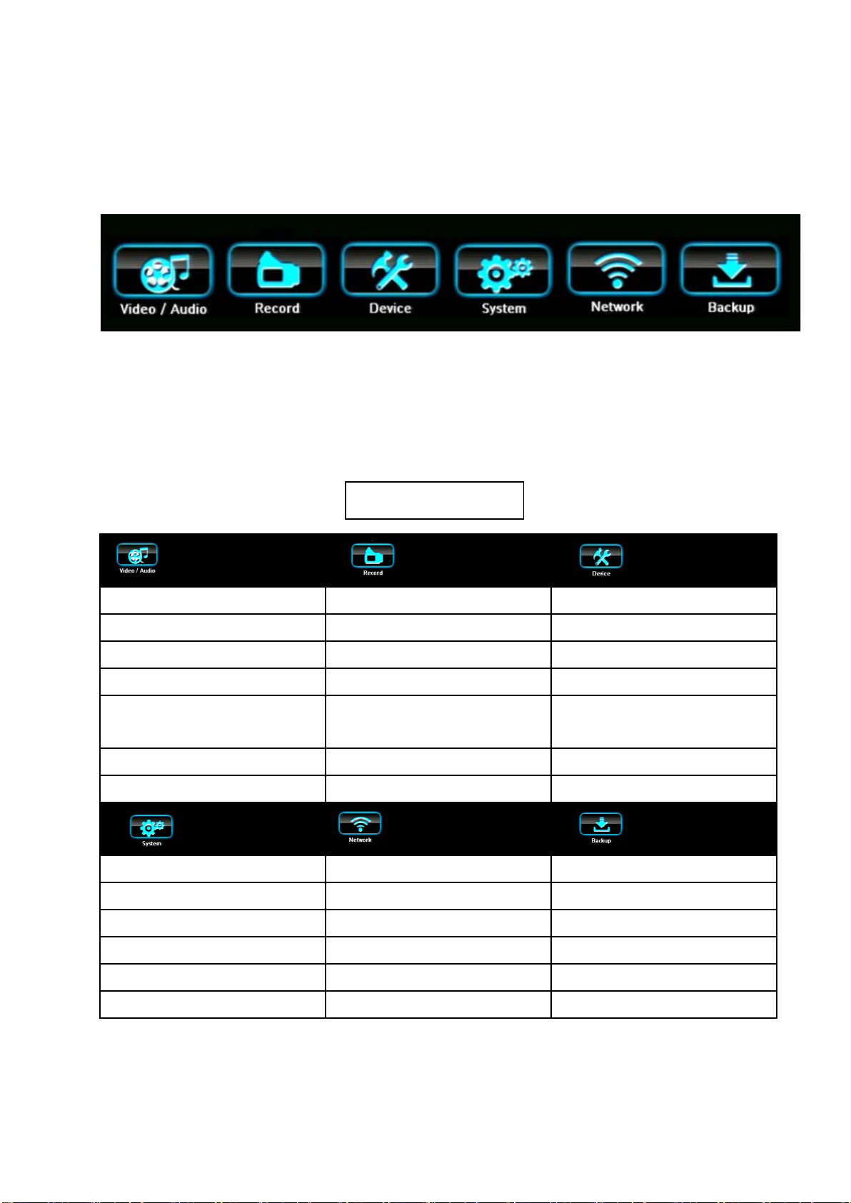
Main Menu Tree
VIDEO/AUDIO
CAMERA POLICY STORAGE
IP CAMERA REGISTRATION SCHEDULE SENSOR/VIDEO LOSS DET.
IP CAMERA SETUP HOLIDAY ALARM SCHEDULE
MONITOR EVENT RECORD DURATION PTZ
SEQUENCE/EVENT DISPLAY RECORD OPTION
RECORD DEVICE
SYSTEM CONTROLLER/
PRINTER DEVICE
OSD/DISPLAY POSITION POS/ATM DEVICE
SCREEN MODE VIDEO ANALYSIS
SYSTEM
DATE/TIME CONNECTION BACKUP
SIGNAL/LANGUAGE/DEVICE NAME PORT/CONNECTION TEST (PING)
CONFIG ID, PASSWORD
LOG INFORMATION DDNS
AUTHORIZATION MGMT NAT TRAVERSAL
EMAIL/SNS
NETWORK BACKUP
25
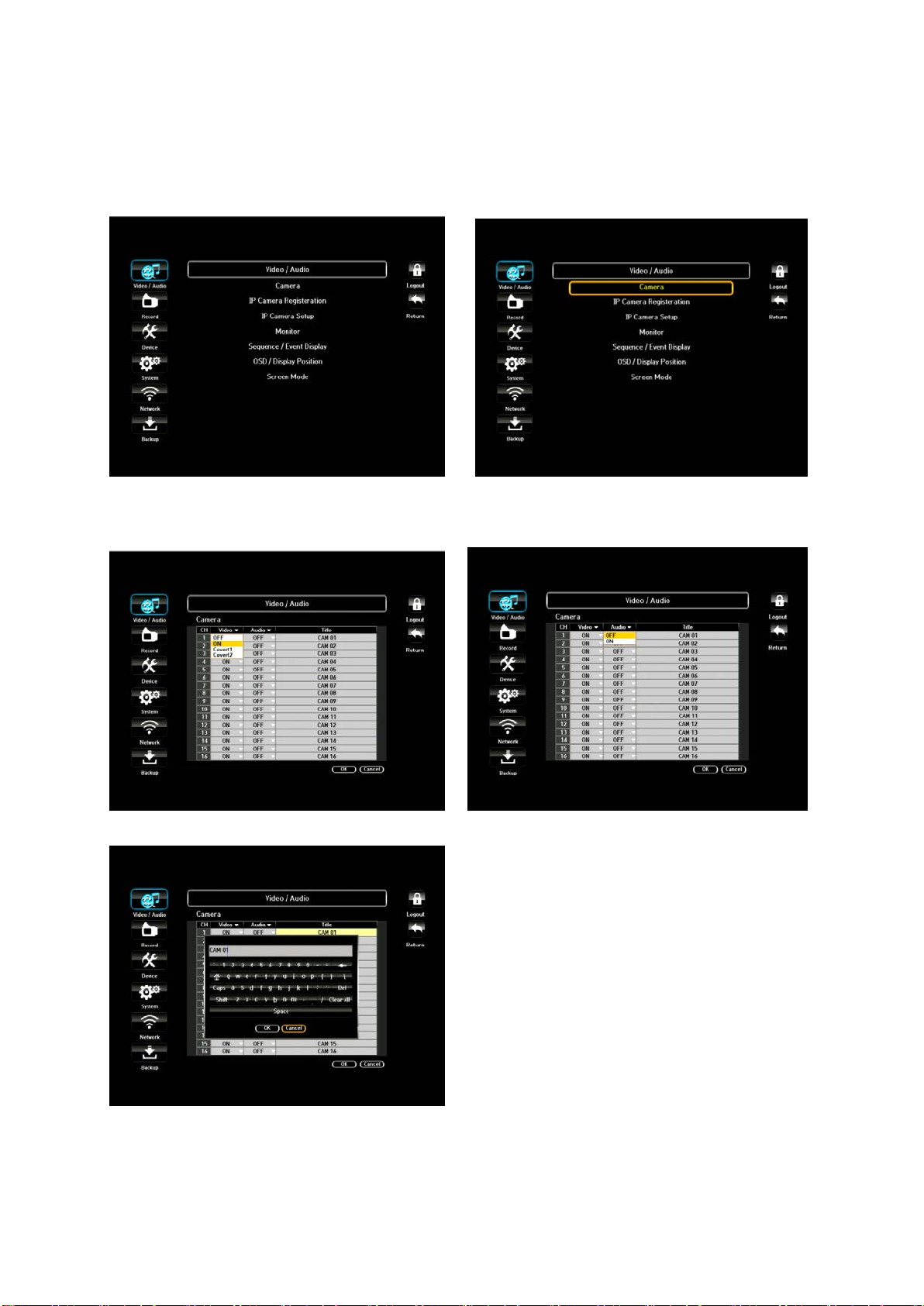
3.1. Video/Audio Setup
There are 5 sub menus under Video/Audio. To exit to main menu, press MENU (or right click on the
mouse) key again.
3.1.1. Camera (Channel) Name and Display
In the Camera menu, you will be able to set up your camera to a desired setting. Click the Camera
menu and it will route you to a Camera setup p age
1) VIDEO: You may select the video ON, OFF,
COVERT 1 or COVERT 2.
ON: Pictures/Images and icons will appear
on screen as normal.
OFF: When the video is switched to OFF,
there is no action taken, (no images/
pictures, recordings, etc.).
COVERT 1: Video/pictures will not appear
and will be blank/black, but icons and
camera name will appear. Despite being in
covert, the NVR will continue to record.
COVERT 2: In this mode, the screen will
be completely blank including icon,
camera names, etc. but will continue to
record.
2) AUDIO: You may select the audio ON or OFF position.
3) TITLE: Create your own title for each camera connected to the NVR by using the virtual
keyboard (up to 15 characters). If you skip this setup, camera # will be displayed on the
screen.
26
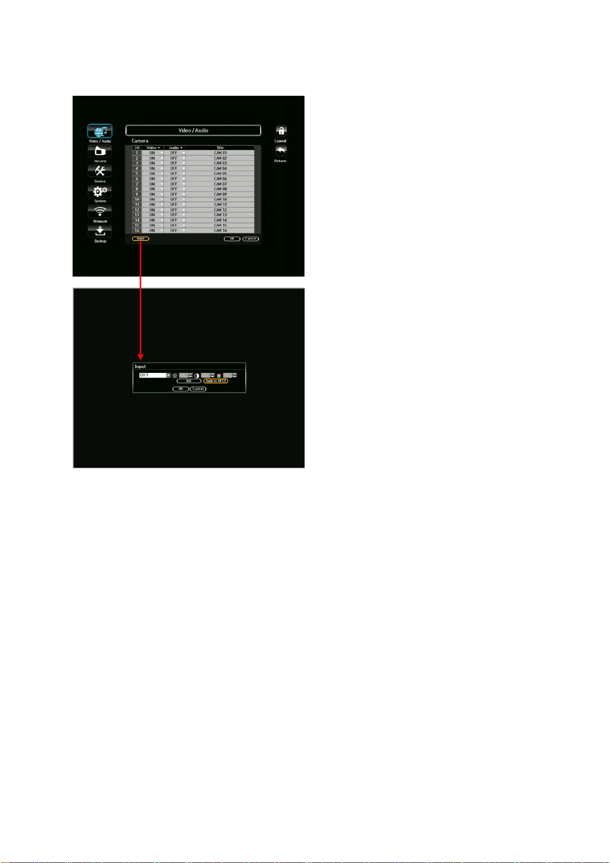
3.1.1. Camera (Channel) Name and Display – Cont.
Screen Input: You can configure your screen to
your preference by adjusting the channel.
1) Brightness
2) Contrast
3) Color
4) Click the <Init> to initialize settings back
to the default 50.
5) When the desired setting is entered,
click <OK>.
27
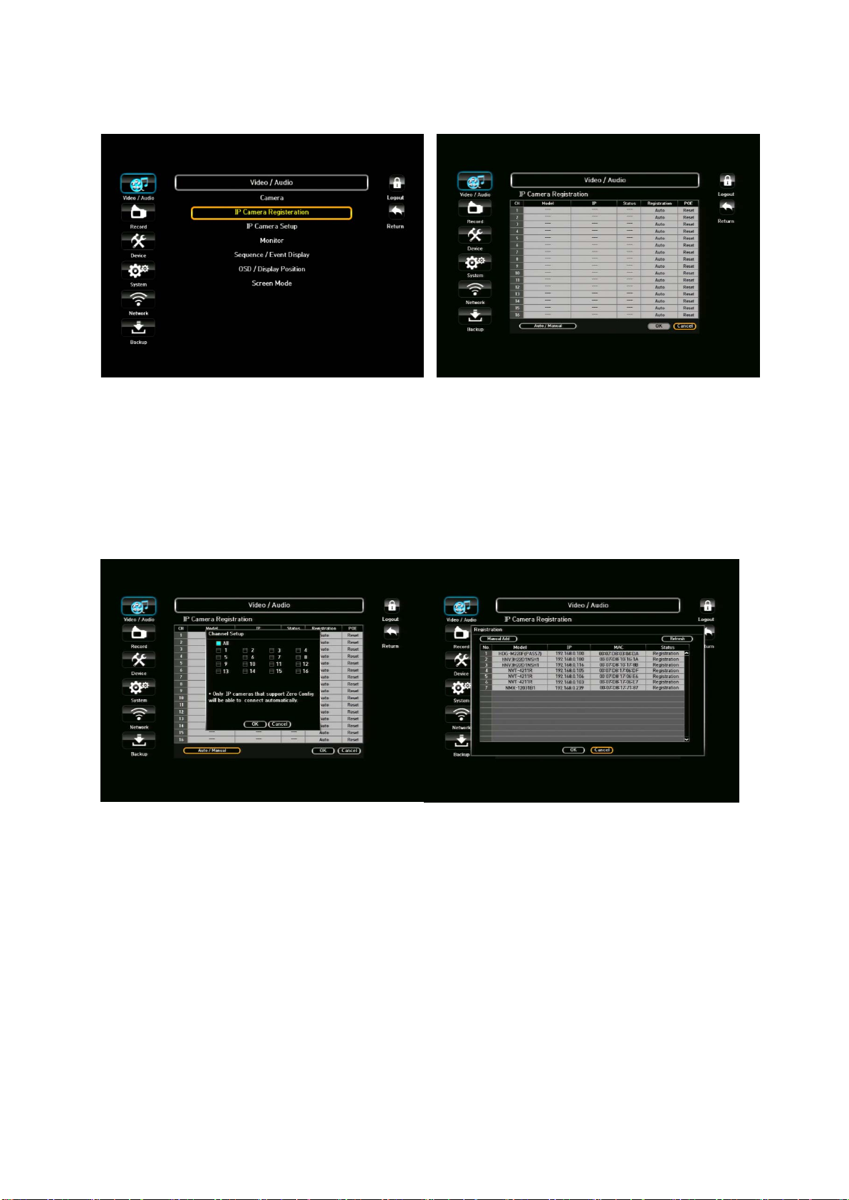
3.1.2. IP Camera Registration
When desired IP cameras are used, you must first register the IP cameras in the IP Camera
Registration menu.
** For Hitron IP cameras, you do not need to register. It will automatically register. For
Samsung and Axis IP cameras, you must perform these two tasks, time sync and then regi ster.
In the IP Camera Registration menu, a list of IP camera will appear that has been detected
automatically. . This will be your default setting. If you wish to manually add IP cameras, click the
Auto/Manual
Auto/Manual: By clicking this button, you will be able to select which channel(s) to register
automatically. If unselected/un-checked, then the channel will not register automatically. You can
select all channels or specific channel(s).
**Only IP cameras that support Zero C onfig will be able to connect automatically.
*Add camera automatically feature is only available with PoE NVRs
Once you have clicked the ADD button, a list of IP cameras will appear on the screen that has been
detected automatically. To select the desired IP camera, simply click the Registration tab under Status
tab.
28

3.1.2. IP Camera Registration – Cont.
IP Camera Registration window will appear. Click the TEST button to see if the connection is
successful. If all the information is correct, you will see SUCCESS indicating that camera is ready for
operation. If the connection has failed, double check the information entered. Once everything is
successful, then click the OK button.
When Refresh button is clicked, it will search all the regi st ered IP cameras again.
If you would like to add remote site IP ca m era, click the Add Manual tab.
A window will appear to enter IP camera information. Click the TEST button to see if the connection is
successful. If it’s successful, click the OK button.
By clicking the IP tab, you will be able to edit your IP camera registration. Once you have made the
changes, click the TEST button to see if it was successful.
29
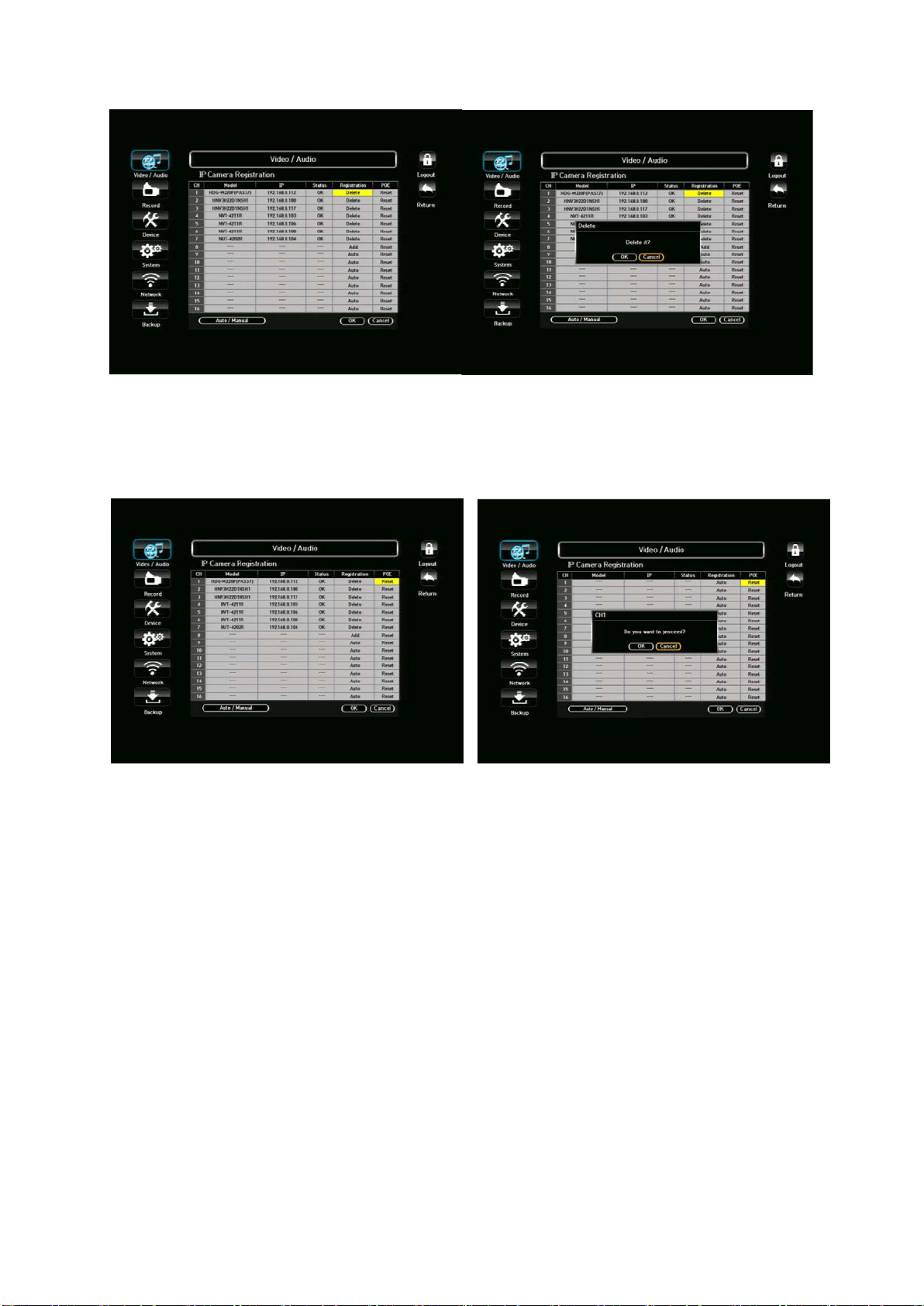
When all IP cameras are registered and ready for use, you can always go back and delete the
cameras.
Simply by clicking the delete button, a windo w will appear in the middle of the page asking if you would
like to delete. Click OK to delete.
PoE Reset: This will power ON/OFF automatically. The advantage of this function is to allow user to
power ON/OFF remotely or if the unit has limited accessibility.
When a RESET tab is clicked, a popup window will appear to confirm with your selection and to
proceed.
30
 Loading...