

Page 1
Instruction and Operation
M A N U A L
20.1_32.0 Inch PVMpro
NETWORKABLE
TFT-LCD MONITOR
Please read this manual thoroughly before use, and keep it handy for future reference.
Page 2

The information in this publication is believed to be accurate in all respects.
However, WE cannot assume responsibility for any consequences resulting from the use thereof.
The information contained herein is subjecT to change WITHOUT NOTICE.
Revisions or new editions to this publication may be issued to incorporate such changes.
2
Page 3
FCC COMPLIANCE STATEMENT
FCC INFORMATION : THIS EQUIPMENT HAS BEEN TESTED AND FOUND TO COMPLY
WITH THE LIMITS FOR A CLASS A DIGITAL DEVICE, PURSUANT TO PART 15 OF THE FCC
RULES. THESE LIMITS ARE DESIGNED TO PROVIDE REASONABLE PROTECTION AGAINST
HARMFUL INTERFERENCE WHEN THE EQUIPMENT IS OPERATED IN A COMMERCIAL
ENVIRONMENT. THIS EQUIPMENT GENERATES, USES, AND CAN RADIATE RADIO
FREQUENCY ENERGY AND IF NOT INSTALLED AND USED IN ACCORDANCE WITH THE
INSTRUCTION MANUAL, MAY CAUSE HARMFUL INTERFERENCE TO RADIO
COMMUNICATIONS. OPERATION OF THIS EQUIPMENT IN A RESIDENTIAL AREA IS LIKELY
TO CAUSE HARMFUL INTERFERENCE IN WHICH CASE THE USER WILL BE REQUIRED TO
CORRECT THE INTERFERENCE AT HIS OWN EXPENSE.
CAUTION : CHANGES OR MODIFICATIONS NOT EXPRESSLY APPROVED BY THE
MANUFACTURED COULD VOID THE USER'S AUTHORITY TO OPERATE THE EQUIPMENT.
THIS CLASS A DIGITAL APPARATUS COMPLIES WITH CANADIAN ICES-003.
CET APPAREIL NUMERIQUE DE LA CLASSE A EST CONFORME A LA NORME NMB-003 DU
CANADA.
CE COMPLIANCE STATEMENT
WARNING
THIS IS A CLASS A PRODUCT. IN A DOMESTIC ENVIRONMENT THIS PRODUCT MAY CAUSE
RADIO INTERFERENCE IN WHICH CASE THE USER MAY BE REQUIRED TO TAKE
ADEQUATE MEASURES.
3
Page 4
WARNINGS AND CAUTIONS:
TO REDUCE THE RISK OF FIRE OR ELECTRIC SHOCK, DO NOT EXPOSE THIS PRODUCT TO
RAIN OR MOISTURE. DO NOT INSERT ANY METALLIC OBJECTS THROUGH THE VENTILATION
GRILLS OR OTHER OPENINGS ON THE EQUIPMENT.
CAUTION:
CAUTIONCAUTION
RISK OF ELECTRIC SHOCK
DO NOT OPEN
CAUTION: TO REDUCE THE RISK OF ELECTRIC SHOCK,
DO NOT REMOVE COVER(OR BACK).
NO USER-SERVICEABLE PARTS INSIDE.
REFER SERVICING TO QUALIFIED SERVICE PERSONNEL.
EXPLANATION OF GRAPHICAL SYMBOLS
The lightning flash with arrowhead symbol, within an equilateral triangle, is intended to alert
the user to the presence of uninsulated "dangerous voltage" within the product's enclosure
that may be of sufficient magnitude to constitute a risk of electric shock to persons.
The exclamation point within an equilateral triangle is intended to alert the user to the
presence of important operating and maintenance (servicing) instructions in the literature
accompanying the product.
PRECAUTIONS
Safety -------------------------------------------- Installation -------------------------------------
Should any liquid or solid object fall into the cabinet,
unplug the unit and have it checked by the qualified
personnel before operating it any further.
Unplug the unit from the wall oulet if it is not going to
be used for several days or more. To disconnect the
cord, pull it out by the plug. Never pull the cord itself.
Allow adequate air circulation to prevent internal heat
build-up. Do not place the unit on surfaces (rugs,
blankets, etc.) or near materials(curtains, draperies)
that may block the ventilation holes.
Height and vertical linearity controls located at the
rear panel are for special adjustments by qualified
personnel only.
Do not install the unit in an extremely hot or humid
place or in a place subject to excessive dust,
mechanical vibration.
The unit is not designed to be waterproof.
Exposure to rain or water may damage the unit.
Cleaning -----------------------------------------
Clean the unit with a slightly damp soft cloth.
Use a mild household detergent. Never use strong
solvents such as thinner or benzine as they might
damage the finish of the unit.
Retain the original carton and packing materials for
safe transport of this unit in the future.
4
Page 5

IMPORTANT SAFEGUARDS
1. Read these instructions.
2. Keep these instructions.
3. Heed all warnings.
4. Follow all instructions.
5. Do not use this apparatus near water.
6. Clean only with dry cloth.
7. Do not block any ventilation openings.
Install in accordance with the manufacturer's instructions.
8. Do not install near any heat sources such as radiators, heat registers, stoves,
or other apparatus (including amplifiers) that product heat.
9. Do not defeat the safety purpose of the polarized or grounding-type plug.
A polarized plug has two blades with one wider than the other.
A grounding type plug has two blades and a third grounding prong.
The wide blade or the third prong are provided for your safety.
If the provided plug does not fit into your outlet, consult an electrician
for replacement of the obsolete outlet.
RISK OF EXPLOSION IF BATTERY IS REPLACED
DISPOSE OF USED BATTERIES ACCORDING
CAUTION
BY AN INCORRECT TYPE.
TO THE INSTRUCTIONS.
10. Protect the power cord from being walked on or pinched particularly at plugs,
convenience receptacles, and the point where thy exit from the apparatus.
11. Only use attachments/accessories specified by the manufacturer.
12. Unplug this apparatus during lightning storms or when unused for long periods of time.
13. Refer all servicing to qualified service personnel.
Servicing is required when the apparatus has been damaged in any way,
such as power-supply cord or plug is damaged, liquid has been spilled or objects
have fallen into the apparatus, the apparatus has been exposed to rain or moisture,
Does not operate normally, or has been dropped.
14. CAUTION - THESE SERVICING INSTRUCTIONS ARE FOR USE BY QUALIFIED
SERVICE PERSONNEL ONLY. TO REDUCE THE RISK OF ELECTRIC SHOCK
DO NOT PERFORM ANY SERVICING OTHER THAN THAT CONTAINED IN THE
OPERATING INSTRUCTIONS UNLESS YOU ARE QUALIFIED TO DO SO.
15. Use Certified/Listed Class 2 power supply transformer only(only 20.1" PVM).
5
Page 6
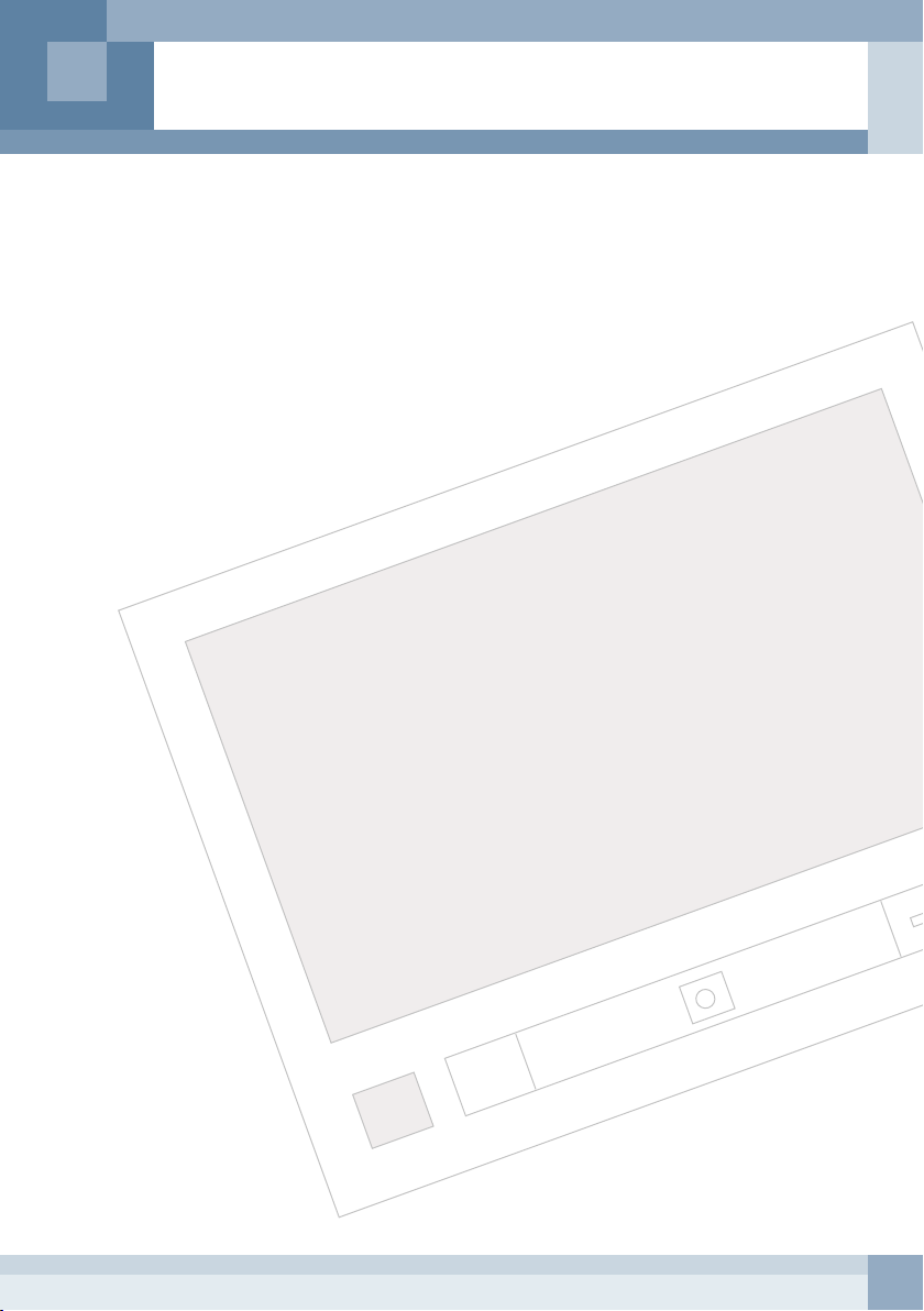
TABLE OF CONTENTS
Chapter 1. DESCRIPTION ---------------------------------------------------------------------------------------- 7
Chapter 2. INSTALLATION -------------------------------------------------------------------------------------- 8
Chapter 3. OPERATION ------------------------------------------------------------------------------------------ 11
Chapter 4. SETUP MODE ---------------------------------------------------------------------------------------- 15
Chapter 5. CLIENT SOFTWARE -------------------------------------------------------------------------------- 26
Features ---------------------------------------------------------------------------------------------------- 7
Accessories ----------------------------------------------------------------------------------------------- 7
Front Panel ------------------------------------------------------------------------------------------------- 8
Rear Panel ------------------------------------------------------------------------------------------------ 9
Remote Control ------------------------------------------------------------------------------------------- 11
Selecting Video Source --------------------------------------------------------------------------------- 12
Operation of Display In Relation to Motion Detection ------------------------------------------- 13
File Navigation -------------------------------------------------------------------------------------------- 14
Using OSD Menu ----------------------------------------------------------------------------------------- 14
Plug and Play ---------------------------------------------------------------------------------------------- 14
Picture ------------------------------------------------------------------------------------------------------- 15
Camera ------------------------------------------------------------------------------------------------------ 15
PC Menu ---------------------------------------------------------------------------------------------------- 18
PIP ------------------------------------------------------------------------------------------------------------ 19
Media -------------------------------------------------------------------------------------------------------- 20
Time/Date --------------------------------------------------------------------------------------------------- 22
OSD ---------------------------------------------------------------------------------------------------------- 23
Configuration ---------------------------------------------------------------------------------------------- 24
Description ------------------------------------------------------------------------------------------------- 26
Network Setup --------------------------------------------------------------------------------------------- 27
Monitoring -------------------------------------------------------------------------------------------------- 29
Media Schedule ------------------------------------------------------------------------------------------- 30
Message Schedule --------------------------------------------------------------------------------------- 33
File Transfer ------------------------------------------------------------------------------------------------ 36
Monitor Adjustment --------------------------------------------------------------------------------------- 37
Emergency Message ------------------------------------------------------------------------------------ 39
Image update ---------------------------------------------------------------------------------------------- 41
Application Update --------------------------------------------------------------------------------------- 43
System Update -------------------------------------------------------------------------------------------- 44
Chapter 6. TROUBLESHOOTING ----------------------------------------------------------------------------- 45
Chapter 7. SPECIFICATION ------------------------------------------------------------------------------------- 46
6
Page 7
CHAPTER 1 - DESCRIPTION
Features
Your Public View Monitor was designed with the latest technology.
This unit includes the following special features.
· Easy-to-use remote control
· Text generation & advertisement transmission via network
· Built-in HDD for storage of media contents
· USB 2.0 connectors (Host & Device)
· Playback of MPEG1,2, 4 and Widows Media Video up to HD quality
· Media file play and Message display on the schedule basis
· Light sensor for sleep mode
· Motion detection capability
· Multiple viewing function with PIP/PBP display
· Powerful audio sound : 5W x 2
· Integrated camera
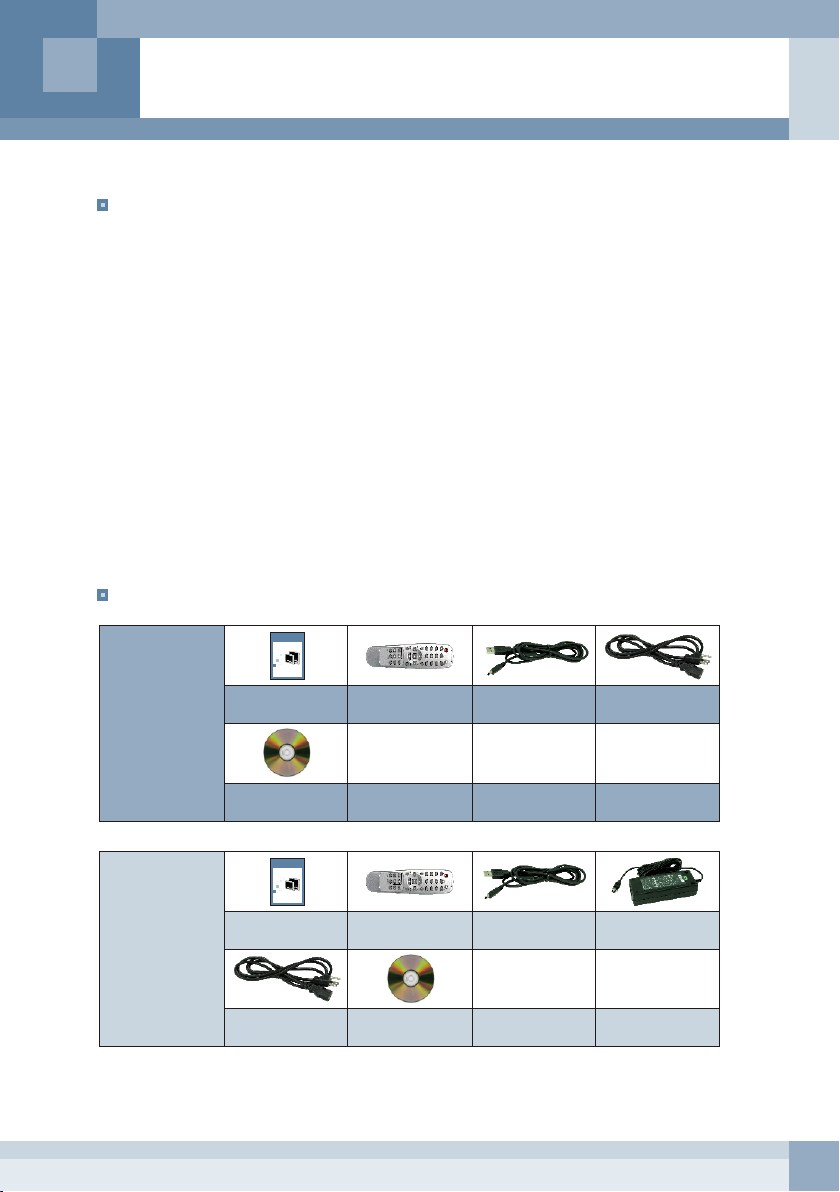
Accessories
Quick Installation
G U I D E
20.1_32.0 Inch PVMpro
NETWORKABLE TFT-LCD MONITOR
20.1_32.0 Inch PVMpro
Please read this manual thoroughly before use, and keep it handy for future reference. Design and specifications are subject to change without notice.
32'' PVM
Quick Guide
Remote Control
& Batteries
USB Cable Power Cord
20'' PVM
CD
Quick Installation
G U I D E
20.1_32.0 Inch PVMpro
NETWORKABLE TFT-LCD MONITOR
20.1_32.0 Inch PVMpro
Please read this manual thoroughly before use, and keep it handy for future reference. Design and specifications are subject to change without notice.
Quick Guide
Remote Control
& Batteries
Power Cord CD
USB Cable Adaptor
7
Page 8
CHAPTER 2 - INSTALLATION
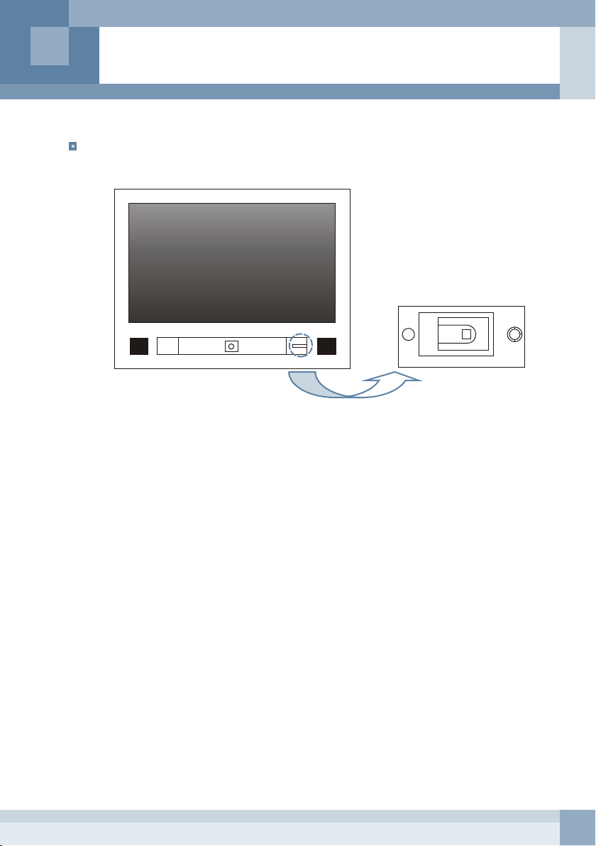
Front Panel
A B A
A.Internal speakers
C
E
D
B.Camera window
The integrated camera is inside.
C.Power indicator
Green : Standby
Red blinking : HDD is working.
No light : Monitor is on and HDD is not working.
D.Remote control sensor
Aim the remote control towards this spot on the monitor.
E.Photo sensor
Detect ambient light.
8
Page 9
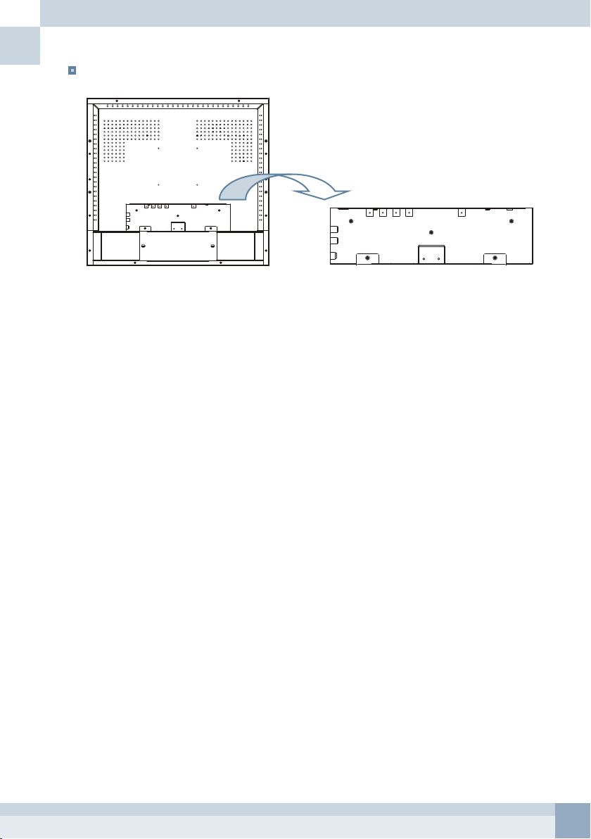
Rear Panel
< 20.1'' PVM >
1
3 4 5 6
2
7
8
1. DC Input Connector
Connect the adapter jack to the DC power connector on the back of the monitor.
2. DC Output Connector
12V DC output connector.
This connector can be used to supply power to an external camera. (12V / 500mA)
3. Video Input Connectors
Two cameras can be connected to the monitor using the BNC connections labeled CA1 and CA2.
Either left or right BNC can be input or output.*
The connectors have auto-termination internal switches.*
4. S-Video Input Connector
Connect S-VHS cable from the video output jack of the camera, VCR or DVD.
5. Integrated Camera Video Output Connector
The video output connector of the integrated camera.
6. Ethernet Connector
Used to connect the monitor to the LAN.
7. Audio Input Connectors
Connect RCA audio cables to the audio output jacks of the VCR or DVD.
9
10
8. Audio Output Connector
Connect audio signals to other audio systems.
The output is the same signal of internal speakers.
9. USB Host Connector
Connect a USB memory to this connector.
10. USB Device Connector
Connect the monitor to the PC using the supplied USB cable.
Your PC detects the monitor and installs it as the mass storage device. And then you can access
A/V files in the integrated HDD.
9
Page 10
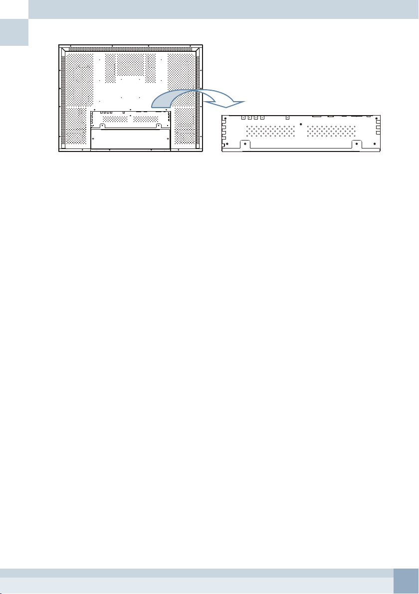
< 32.0'' PVM >
1
2
3 4 5 6
7
10
11
1. DC Output Connector
12V DC output connector.
This connector can be used to supply power to an external camera. (12V / 500mA)
2. Video Input Connectors
Two cameras can be connected to the monitor using the BNC connections labeled CA1 and CA2.
Either left or right BNC can be input or output.*
The connectors have auto-termination internal switches.*
3. S-Video Input Connector
Connect S-VHS cable from the video output jack of the camera, VCR or DVD.
4. Integrated Camera Video Output Connector
The video output connector of the integrated camera.
5. DVI Connector
Connect DVI video signal to this connector using the supplied video cable.
6. D-SUB Connector
Connect the 15-pin D-SUB of the video signal cable from the VGA connection of a PC to the back
of the PVMpro.
7. Ethernet Connector
Used to connect the monitor to the LAN.
8. AC Input Socket
Connect the AC power cord to the AC Input socket on the back of the monitor.
9. AC Power Switch
Used to supply power to the monitor.
10. Audio Input Connectors
Connect RCA audio cables to the audio output jacks of the VCR or DVD.
- Audio 1 : CAMERAs
- Audio 2 : All other videos except cameras
11. Audio Output Connector
Connect audio signals to other audio systems. The output is the same signal of internal speakers.
12. Component Video Input Connector
Connect the component video source using the (x3 connectors) RCA cable from a DVD or other
equipment that support the component video output.
13. USB Host Connector
Connect a USB memory device to this connector.
14. USB Device Connector
Connect the monitor to the PC using the supplied USB cable.
Your PC detects the monitor and installs it as the mass storage device. And then you can access
A/V files in the integrated HDD.
8
9
12
13
14
10
Page 11
CHAPTER 3 - OPERATION
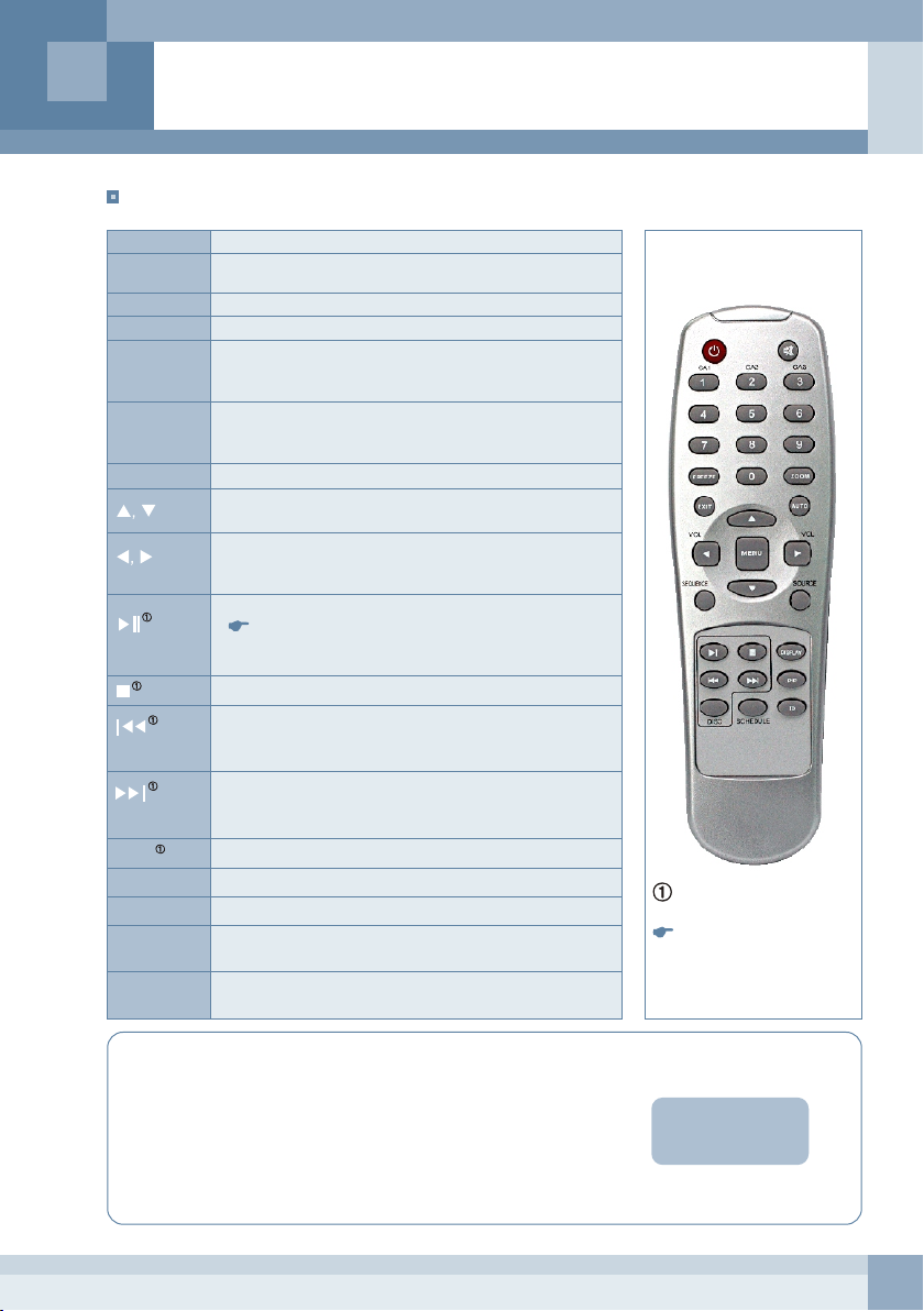
Remote Control
PWR
0 ~ 9
CA1 & CA2
Mute
EXIT
AUTO
MENU
SOURCE
DISC
DISPLAY
PIP
SCHEDULE
ID
Turn the monitor on and off.
Numeric keys
Select CA1 or CA2 as the main video source.
Cuts off the sound.
Exit from the OSD or go to the previous OSD window.
Allows the monitor to self-adjust to the incoming video
signal. The values of clock, phase and position are
adjusted automatically. (Used in PC mode)
Access the OSD menu.
This button also used when selecting the video source.
(In this case this button is used as the enter button.)
Select the MAIN or PIP video source.
Move up or down on the menu list.
Adjust the chosen item (IP, Time and Date etc..).
Go to the sub menu of the selected option.
Adjust the chosen item.
Increase or decrease the volume of internal speakers.
Play media files or pause the media file playing.
The media file over 2GB is not supported.
Display the contents list of the selected folder.
Go to the sub-directory.
Stop playback of the media file.
Move up in the DISC menu list.
During playback of a media file, this button is used to
play the previous media file.
Move down in the DISC menu list.
During playback of a media file, this button is used to
play the next media file.
Display DISC menu or exit from the DISC menu.
Display brief current monitor status.
Turn the PIP window on or off.
Press this button to start the media and message
schedule.
Use this button to control the monitor that has the
same ID number.
This button is used to access
media files in storage devices.
Freeze and ZOOM buttons are
not available.
Using the ID button of the remote control.
A specific monitor can be controlled using the ID button on the remote
control when several monitors are installed side by side.
Refer to following instructions.
1. Set Remote Control ID of the monitor using the supplied remote control.
2. Pressing the ID button will display the current IDs of the monitor and
the remote control.
3. Press the numeric number that is same as the specific monitor.
4. Use the remote control to customize your monitor that is matched to the
ID of the remote control.
Remote Control ID
0 0
11
Page 12
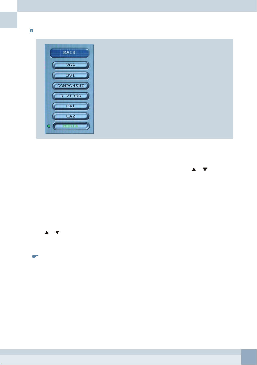
Selecting Video Source
Selecting Main Video Source
- Press the SOURCE button.
- Press the MENU button after selecting the video source to be displayed using or .
- To cancel and maintain the current video source, press the EXIT button of the
remote control.
Selecting PIP Video Source
- Press the PIP button to activate the PIP window.
- Press the SOURCE button twice.
- Press the MENU button after selecting the video source to be displayed on the PIP window
using or .
- To cancel and maintain the current video source, press the EXIT button of the
remote control.
CA1, CA2 and S-VIDEO can't be displayed simultaneously on the screen.
For example, if CA1 is selected as the main video source, it is impossible to choose CA1
or S-VIDEO as the PIP video source.
12
Page 13
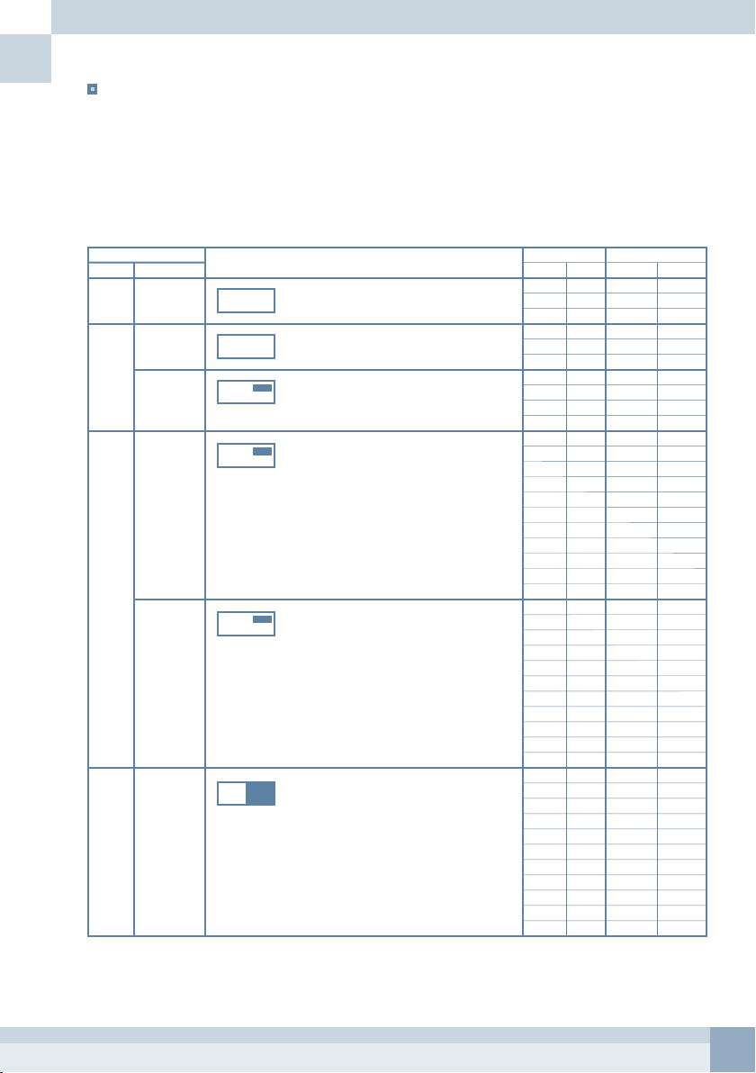
Operation of Display in Relation to Motion Detection
There are various display modes in relation to Motion Detection and PIP mode options.
Refer to the following table for overview of operation of display when motion occurs at one of the cameras.
C : Camera S : S-VIDEO M : MEDIA
D : DVI V : VGA H : COMPONENT
X : NO PICTURE
OSD
PIP PICTURE
OFF Any
Selection
PIP1 FULL
PIP
PIP2 FULL
PIP
PBP Any
Selection
Description
The image on the screen switches from the current
main video to the camera video that has a motion.
The image on the screen switches from the curren
main video to camera video that has a motion.
The camera video that has a motion only appears
on the PIP window for DWELL TIME that was set
in CAMERA/MOTION/DWELL TIME.
The PIP window is always activated.
The camera video that has a motion is always
displayed on the main window.
The PIP window image is varies depend on the
previous PIP video source.
The image on the PIP window becomes the
camera video that has a motion except that the main
video was set to CAMERA or S-VIDEO.
The left window is the main video and the right
window is the PIP video.
When motion occurs at one of the cameras,
the PIP window switches to the camera window
that has a motion.
Current Display Motion Display
PIP
MAIN
X
C
X
S
X
M/D/V/H
C
X
S
X
M/D/V/H
X
C
X
S
X
M
X
D/V/H
X
C
M
C
H/D/V
S
M
S
H/D/V
M
C
M
S
M
H/D/V
H/D/V
C
H/D/V
S
H/D/V
M
H/D/V
H/D/V
C
M
C
H/D/V
S
M
S
H/D/V
M
C
M
S
M
H/D/V
H/D/V
C
H/D/V
S
H/D/V
M
H/D/V
H/D/V
C
M
C
H/D/V
S
M
S
H/D/V
M
C
M
S
M
H/D/V
H/D/V
C
H/D/V
S
H/D/V
M
H/D/V
H/D/V
MAIN
C (M)
C (M)
C (M)
C (M)
C (M)
C (M)
C (C)
C (S)
M (M)
D/V/H
C (M)
C (M)
C (M)
C (M)
C (M)
C (M)
C (M)
C (M)
C (M)
C (M)
C (M)
C (C)
C (C)
C (C)
C (C)
M (M)
M (M)
M (M)
H/D/V (C)
H/D/V (C)
H/D/V (C)
H/D/V (C)
C (C)
C (C)
C (C)
C (S)
M (M)
M (M)
M (M)
H/D/V (C)
H/D/V (C)
H/D/V (C)
H/D/V (C)
PIP
X
X
X
X
X
X
X (M)
X (M)
C (X)
C (M)
M (C)
H/D/V (C)
M (C)
H/D/V (C)
M (C)
M (C)
H/D/V (C)
H/D/V (C)
H/D/V (C)
M (C)
H/D/V (C)
M (M)
H/D/V (M)
M (M)
H/D/V (M)
C (C)
C (C)
C (C)
C (M)
C (M)
C (M)
C (M)
M (M)
H/D/V (M)
M (M)
H/D/V (M)
C (C)
C (C)
C (C)
C (M)
C (M)
C (M)
C (M)
( ) MOTION REVERSE : ON
13
Page 14
File Navigation
You can access and play media files using the remote control.
And some playback options are available in the OSD menu.
If the Media Schedule is operating, stop the Media Schedule by pressing the SCHEDULE button
on the remote control before accessing the media files of the HDD or USB memory device.
/
[+]hd1
[+]usb1
< DISC MENU >
- Press the DISC button to display storage devices or contents of it.
- To move up or down in the DISC menu, use or .
- To play the selected video or audio file, press .
- To stop playing media file temporarily, press .
- is used to play next media file in the list during playback.
- is used to play previous media file in the menu list during playback.
- Press to stop playback and go to the DISC menu.
Using OSD Menu
Pressing the MENU button places the unit into the programming mode.
Setup mode allows you to customize the unit operation to suit a specific application.
In the setup mode, the arrow buttons are used to move DOWN, UP, LEFT and RIGHT in the OSD
Setup menu. The OSD display time can be adjusted in the OSD setup menu.
All chosen values and items are memorized when exiting the OSD menu.
- Press the MEMU button.
- Move up or down the menu list using or .
- Display the sub-menu of the selected item using .
- Adjust the chosen item using or .
- Display previous menu or exit from the OSD using the EXIT button.
Plug and Play (VGA & DVI)
This monitor meets VESA Plug and Play standards, which eliminates complicated and time-consuming
setup. It allows you to install your monitor in a Plug and Play compatible system without the usual setup
hassles and confusion. Your PC system can easily identify and configure itself for use with your display.
14
Page 15
CHAPTER 4 - SETUP MODE
MAIN MENU
All functions in the OSD menu are controlled via the supplied remote control.
MAIN MENU
PICTURE
CAMERA
PC MENU
PIP
MEDIA
TIME / DATE
OSD
CONFIGURATION
PICTURE
The PICTURE menu allows you to modify the picture quality by adjusting the contrast, brightness and
other options.
Pressing the MENU button will place the unit into the
programming mode.
This monitor has 8 main OSD items.
VOLUME
CONTRAST
BRIGHTNESS
COLOR
TINT
SHARPNESS
AUTO COLOR
PICTURE
OFF
25
128
128
128
128
2
Press the MENU button and move indication bar to PICTURE.
Press u to display sub-menu of PICTURE.
Select one of option using p or q .
Adjust the option selected using t or u .
*) TINT is only available in NTSC system.
AUTO COLOR
This option is used to adjust the video level automatically in the VGA and COMPONENT mode.
CAMERA
This option is used to adjust options of each camera.
CAMERA
SELECTION
TITLE
MOTION
ADJUSTMENT
SEQUENCE
Press the MENU button and select CAMERA using p or q .
Press u to display sub-menu of CAMERA.
15
Page 16

SELECTION
This option is used to select the camera for display.
Select INT to display and process the integrated camera.
Select EXT to display and process an external camera.
CA1
CA2
SELECTION
INT
EXT
Press the MENU button and select CAMERA using p or q .
Press u to display sub-menu of CAMERA.
Select SELECTION and press u to display its sub-menu.
Select INT or EXT using t or u .
TITLE
TITLE setup option allows you to modify the name of each camera.
Display option is used to select whether or not the screen displays the camera title.
CA1 EXT
CA1 INT
CA2 EXT
CA2 INT
DISPLAY
TITLE
CA1 EXT
CA1 INT
CA2 EXT
CA2 INT
ON
Press the MENU button and select the CAMERA using p or q .
Press u to display sub-menu of CAMERA.
Select TITLE and press u to display its sub-menu.
Locate indication bar at CA1 EXT and press u to change the first
character.
Change first character of the CA1 EXT using p or q .
Press t or u to change character position.
Press the EXIT button to finish changing of the camera title.
To activate display of the camera title, select ON of the DISPLAY
option.
MOTION
This monitor has a motion detection function to support automatic switching from MEDIA to the internal
camera or an external camera.
Motion detection is only available with CA1 and CA2.
The Motion Sensitivity and other options for motion detection can be adjusted in this setup menu.
MOTION
CAMERA
MOTION ENABLE
SENSITIVITY
CAPTURE TIME
DWELL TIME
MOTION TIME
PICTURE FULL
MOTION REVERSE
CA1
ON
10
10 SEC
10 SEC
06:00:00
18:00:00
FULL
OFF
Press the MENU button and select CAMERA using p or q .
Press u to display sub-menu of CAMERA.
Select MOTION and press u to display its sub-menu.
Select the option to be changed using p or q .
Change the chosen option using t or u .
CAMERA
This menu is used to select the camera for adjustment of motion detection options.
16
Page 17

MOTION ENABLE
This option is used to activate or deactivate the motion detection function.
''ON" : Motion detection of selected camera is enabled.
"OFF" : Motion detection of selected camera is disabled.
SENSITIVITY
Use the SENSITIVITY option to adjust the sensitivity of motion detection.
To increase (decrease) the motion detection sensitivity of the internal camera, increase (decrease) the
sensitivity value.
CAPTURE TIME
CAPTURE TIME is the interval that the motion detection is processed.
When it is set to 10 SEC, the motion detection is process at every 10 seconds.
This means that the minimum switching interval from the MEDIA to the camera that has motion is 10
seconds when PIP MODE has been set to off.
DWELL TIME
If there is a motion in the field of view of a camera, the main screen switches to the camera image that
has motion for a length of time set in the DWELL TIME setup menu and then returns to the previous
display mode.
DWELL TIME is the time that the motion detected camera is displayed on the screen.
MOTION TIME
This option is used to set when the motion detection function is active.
The time represented by the upper line is the start of motion detection and the lower line represents the
end of motion detection time period.
The motion detection function only works during MOTION TIME.
If the user wants to use motion detection all the time, adjust the time of lower line sooner than the time
of upper line.
PICTURE
This option is used to select the display method of the motion camera.
When it was set to FULL, the motion camera is displayed in full in the main window and when it was set
to PIP, the motion camera is displayed in the PIP window.
MOTION REVERSE
When motion occurs at one of the cameras, user can select CAMERA or MEDIA as the motion event
display on MAIN or PIP window.
"ON" : MEDIA is the video of motion event display.
"OFF" : CAMERA is the video of motion event display.
ADJUSTMENT
This option is used to adjust picture quality of each camera.
ADJUSTMENT
TITLE
CONTRAST
BRIGHTNESS
COLOR
TINT *)
SHARPNESS
CA1
25
25
25
25
1
Press the MENU button and select CAMERA using p or q .
Press u to display sub-menu of CAMERA.
Select ADJUSTMENT and press u to display its sub-menu.
Locate horizontal bar at TITLE and then select the camera
to be adjusted using t or u .
Select the option using p or q .
Change value of the chosen option using t or u .
*) TINT is only available in NTSC system.
17
Page 18

SEQUENCE
This option is used to set the dwell time of the selected camera when the monitor is operated in the
SEQUENCE mode.
CA1
CA2
SEQUENCE
SEQUENCE
3 SEC
3 SEC
OFF
Press the MENU button and select CAMERA using p or q .
Press u to display sub-menu of CAMERA.
Select SEQUENCE and press u to display its sub-menu.
Select the option to be changed using p or q .
Change value of the chosen option using t or u .
SEQUENCE
Pressing SEQUENCE of the remote control or selecting
SEQUENCE to ON in the OSD menu sequences cameras.
PC MENU
The PC MENU allows you to modify the picture quality and the picture position in the VGA mode.
PC MENU
AUTO CONFIGURATION
CLOCK
PHASE
POSITION
COLOR TEMPERATURE
OFF
127
0
AUTO CONFIGURATION
Allow the monitor to self-adjust to the incoming video signal.
The values of clock, phase and position are adjusted automatically.
CLOCK
Use Clock to minimize any vertical bars or strips visible on the screen background.
Press the MENU button and select PC MENU using p or q .
Press u to display sub-menu of PC MENU.
Locate horizontal bar at AUTO CONFIGURATION,
CLOCK or PHASE using p or q .
Adjust the option selected using t or u .
PHASE
Use Phase to adjust the focus of the display.
This item allows you to remove any horizontal noise and clear or sharpen the image of characters.
POSITION
Use POSITION to adjust the horizontal and vertical position of the image on the monitor screen.
POSITION
AUTO CONFIGURATION
CLOCK
PHASE
POSITION
COLOR TEMPERATURE
OFF
127
0
Press the MENU button and select PC MENU using p or q .
Press u to display sub-menu of PC MENU.
Locate horizontal bar at POSITION using p or q .
Press u to display sub-menu of it.
Use p, q, t or u to adjust the position of the image on the
screen.
18
Page 19

COLOR TEMPERATURE
Use COLOR TEMPERATURE to change the screen color standard.
COLOR TEMPERATURE
COLOR TEMPERATURE
RED
GREEN
BLUE
USER
255
255
255
Press the MENU button and select PC MENU using p or q .
Press u to display sub-menu of PC MENU.
Locate horizontal bar at COLOR TEMPERATURE using p or q .
Press u to display its sub-menu.
Use t or u to change the value to DEFAULT, 4200K or USER.
PIP
This monitor can display the PIP window.
This setup menu is used to adjust PIP window options.
This option is also used to display two video sources side by side (PBP).
PIP MODE
This option is used to activate or deactivate the PIP window.
The size and the position of the PIP window can be adjusted when PIP MODE was set to PIP2.
PIP CONTROL
PIP MODE
OFF
Press the MENU button and select PIP using p or q .
Press u to display sub-menu of PIP.
Use t or u to change the value to OFF, PIP1, PIP2 or PBP.
OFF
PIP1
PIP2
PBP
PIP window is disabled.
If there is a motion in the field of view of the camera and PICTURE in the MOTION
setup menu is set to PIP, the camera video appears on the PIP window for the
duration of time that was set in the MOTION/DWELL TIME.
The PIP window is always visible and any video sources can be selected as the
PIP video source.
To display the camera video that has a motion on the PIP window when other video
sources (not cameras) are selected as the PIP video source, set MOTION options
as followings.
- CAMERA / MOTION / MOTION ENABLE : ON
- CAMERA / MOTION / PICTURE : PIP
- CAMERA / MOTION / MOTION REVERSE : OFF
Two video sources that were chosen as MAIN and PIP video sources are displayed
side by side on the screen.
19
Page 20

PIP SIZE
This option is used to adjust the size of the PIP window.
PIP CONTROL
PIP MODE
PIP SIZE
POSITION
PIP 2
SMALL
Press the MENU button and select PIP using p or q .
Press u to display sub-menu of PIP.
Locate horizontal bar at PIP SIZE.
Use t or u to change the value to SAMLL, MEDIUM or LARGE.
POSITION
This option is used to adjust the position of the PIP window.
PIP CONTROL
PIP MODE
PIP SIZE
POSITION
PIP 2
SMALL
Press the MENU button and select PIP using p or q .
Press u to display sub-menu of PIP.
Locate horizontal bar at POSITION using p or q and then
press u.
Use p, q, t or u to change the position of the PIP window.
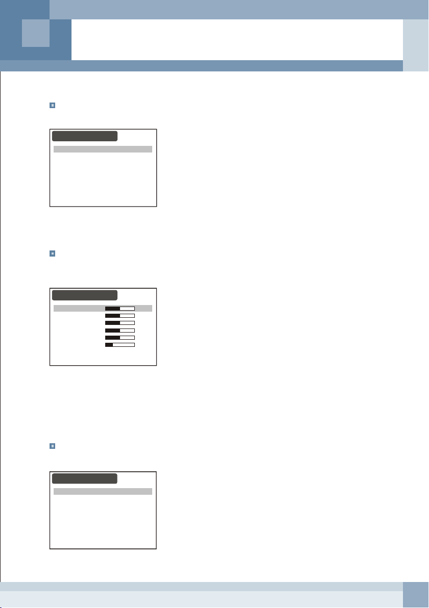
MEDIA
This option is used to adjust options related to the network environment, file playback, system update and
others.
PC MENU
AUTO CONFIGURATION
CLOCK
PHASE
POSITION
COLOR TEMPERATURE
OFF
127
0
Press the MENU button and select MEIDA using p or q .
Press u to display sub-menu of MEIDA.
NETWORK
Network parameters can be input in this option. These parameters are used for the remote client.
PIP CONTROL
PIP MODE
PIP SIZE
POSITION
PIP 2
SMALL
Press the MENU button and select MEIDA using p or q .
Press u to display sub-menu of MEIDA.
Locate horizontal bar at IP ADDRESS, SUBNET MASK or
GATEWAY.
Press t or u to select the active position of the selected option.
Press p or q to change selected value.
20
Page 21

MEDIA PLAY
Use this option to set options related to the play of media files.
MEDIA PLAY
MEDIA PLAY
REPLAY
JPEG PLAY TIME
FOLDER
OFF
10 SEC
MEDIA PLAY & REPLAY
This option sets whether media files in the selected folder are
played only once or played as a continuous loop.
JPEG PLAY TIME
This option sets how long each photo image is displayed.
SYSTEM
This option is composed of 3 available items related to the media system.
Use this option to reboot the media system or upgrade softwares using the USB memory.
REBOOT
Select REBOOT “ON”, to reboot the media system.
The reboot process does not affect the VGA, DVI, COMPONENT, S-VIDEO, CA1 and CA2 display.
During the reboot process, USB, Ethernet and others related to the media system are re-initialized.
SYSTEM
REBOOT
SYSTEM UPDATE
APPLICATION UPDATE
OFF
OFF
OFF
Press the MENU button and select MEIDA using p or q .
Press u to display sub-menu of MEIDA.
Locate horizontal bar at SYSTEM then press u .
Locate horizontal bar at reboot.
Select REBOOT “ON” using t or u .
Press the EXIT button of the remote control to reboot the media
system.
SYSTEM & APPLICATION UPDATE
SYSTEM UPDATE is the re-write of all flash contents.
The flash memory contains OS and drivers for specific devices.
It takes about 4~5 minutes.
APPLICATION UPDATE is the update of the application program that is in the integrated HDD.
Before execution of update, connect the USB memory that contains update files.
Stop the Media schedule before SYSTEM & APPLICATION update.
Do not unplug the power during update.
Reboot after completion of update.
The file name of SYSTEM UPDATE must be romfs_hitron32.bin(32”).
The file name of SYSTEM UPDATE must be romfs_hitron20bin(20”).
The file name of APPLICATION UPDATE must be pmp32.pvm(32”).
The file name of APPLICATION UPDATE must be pmp20.pvm(20”).
21
Page 22

SYSTEM
REBOOT
SYSTEM UPDATE
APPLICATION UPDATE
OFF
OFF
OFF
Press the MENU button and select MEIDA using p or q .
Press u to display sub-menu of MEIDA.
Locate horizontal bar at SYSTEM then press u.
Locate horizontal bar at SYSTEM UPDATE or
APPLICATION UPDATE.
Select SYSTEM UPDATE or APPLICATION UPDATE “ON”
using t or u .
Press the EXIT button of the remote control to update
SYSTEM or APPLICATION.
UPDATE
UPDATE SUCCESS
UPDATE FAIL
USB Not Found !!!
The upper message appears during update.
The upper message appears when update is completed
successfully.
If there is no USB memory connected, the upper message
will appear.
TIME/DATE
DATE FORMAT
The option on the time and date setup screen is date format.
This is used to select between the following three date formats:
US(default)
EURO
ASIA
TIME / DATE
DATE FORMAT
DATE
TIME
DISPLAY
MM / DD / YYYY
DD / MM / YYYY
YYYY / MM / DD
US
MM/DD/YYYY
HH:MM:SS
ON
Press the MENU button and select TIME / DATE using p or q .
Press u to display sub-menu of TIME / DATE.
Locate horizontal bar at DATE FORMAT using p or q .
Change this option to US, EURO or ASIA using t or u .
22
Page 23

DATE & TIME
These options are used to set the current date and time.
The format displayed on the screen is dependent on the date format option set in the preceding steps.
TIME / DATE
DATE FORMAT
DATE
TIME
DISPLAY
US
MM/DD/YYYY
HH:MM:SS
ON
Press the MENU button and select TIME / DATE using p or q .
Press u to display sub-menu of TIME / DATE.
Locate horizontal bar at DATE or TIME using p or q .
Press t or u to select one of the items.
Change the selected value of the selected item using p or q .
DISPLAY
The display option on the time and date setup screen allows you to select whether or not to display time
and date on the screen. The default option is ON.
TIME / DATE
DATE FORMAT
DATE
TIME
DISPLAY
US
MM/DD/YYYY
HH:MM:SS
ON
Press the MENU button and select TIME / DATE using p or q .
Press u to display sub-menu of TIME / DATE.
Locate horizontal bar at DISPLAY using p or q .
Press t or u to select "ON" or "OFF".
OSD
Use the OSD Menu to adjust the OSD window.
The OSD Position and other options can be adjusted in this setup menu.
LANGUAGE
OSD TIME
POSITION
BLENDING
OSD
ENGLISH
40 SEC
4
Press the MENU button and select OSD using p or q .
Press u to display sub-menu of OSD.
Select one of option using p or q .
Change the option using t or u .
(Use t , u , p and q to move the OSD window on the screen.)
LANGUAGE
Selects OSD language displayed. Currently only English is supported.
OSD TIME
The OSD TIME option is used to adjust the on-screen display time. It supports up to 120 seconds.
POSITION
This option is used to move the OSD window horizontally or vertically.
BLENDING
This option is used to change the opaqueness of the background of the OSD.
23
Page 24

CONFIGURATION
The configuration setup screen allows you to make changes to the security option
and other options related to the system.
CONFIGURATION
PASSWORD
VIDEO SYSTEM
PHOTO INPUT
REMOTE CONTROL ID
RECALL
SCALING
OFF
NTSC
OFF
OFF
OFF
EXPAND
PASSWORD
The password option is used to protect programming setup from unauthorized access.
If this option is ON, pressing MENU to enter the main menu setup mode will display
the password confirmation screen.
CONFIGURATION
PASSWORD
VIDEO SYSTEM
PHOTO INPUT
REMOTE CONTROL ID
RECALL
SCALING
OFF
NTSC
OFF
OFF
OFF
EXPAND
VIDEO SYSTEM
Select the video system that is used in your region.
CONFIGURATION
PASSWORD
VIDEO SYSTEM
PHOTO INPUT
REMOTE CONTROL ID
RECALL
SCALING
OFF
NTSC
OFF
OFF
OFF
EXPAND
Press the MENU button and select CONFIGURATION using
p or q .
Press u to display sub-menu of CONFIGURATION.
Press the MENU button and select CONFIGURATION using
p or q .
Press u to display sub-menu of CONFIGURATION.
Select PASSWORD using p or q .
Set PASSWORD to "ON".
(The PASSWORD window appears)
Enter new the 4-digits of password.
(The PASSWORD CONFIRMATION window appears.)
Enter the 4-digits of password that had been entered.
Press the MENU button and select CONFIGURATION using
p or q .
Press u to display sub-menu of CONFIGURATION.
Select VIDEO SYSTEM using p or q .
Change VIDEO SYSTEM to NTSC or PAL using t or u .
PHOTO INPUT
This monitor can be turned off and goes to power saving mode if there is low ambient light by setting
PHOTO INPUT to "ON".
CONFIGURATION
PASSWORD
VIDEO SYSTEM
PHOTO INPUT
REMOTE CONTROL ID
RECALL
SCALING
OFF
NTSC
OFF
OFF
OFF
EXPAND
Press the MENU button and select CONFIGURATION using
p or q .
Press u to display sub-menu of CONFIGURATION.
Select PHOTO INPUT using p or q .
Change this option to "ON" or "OFF" t or u .
- ON : The monitor turns off when ambient light is low.
- OFF : The monitor doesn't go to low power mode.
24
Page 25

REMOTE CONTROL ID
Use the REMOTE CONTROL ID setup menu to set the ID of the monitor.
This feature is convenient when there are several monitors installed.
Set ID to other value except 0 to adjust the monitor that has the same number.
CONFIGURATION
PASSWORD
VIDEO SYSTEM
PHOTO INPUT
REMOTE CONTROL ID
RECALL
SCALING
OFF
NTSC
OFF
0
OFF
EXPAND
Press the MENU button and select CONFIGURATION using
p or q .
Press u to display sub-menu of CONFIGURATION.
Select REMOTE CONTROL ID using p or q .
Change the value using t or u .
RECALL
This option allows you to return to the unit to factory-defined defaults.
CONFIGURATION
PASSWORD
VIDEO SYSTEM
PHOTO INPUT
REMOTE CONTROL ID
RECALL
SCALING
OFF
NTSC
OFF
OFF
OFF
EXPAND
Press the MENU button and select CONFIGURATION using
p or q .
Press u to display sub-menu of CONFIGURATION.
Select RECALL using p or q .
Set the option to "ON" using t or u .
Press the EXIT button.
SCALING (32'')
User can adjust the picture size to 4:3 or original image size on the screen.
There are three options EXPAND, ASPECT and 1:1.
This option can be configured with VGA and DVI.
CONFIGURATION
PASSWORD
VIDEO SYSTEM
PHOTO INPUT
REMOTE CONTROL ID
RECALL
SCALING
OFF
NTSC
OFF
OFF
OFF
EXPAND
Press the MENU button and select CONFIGURATION using
p or q .
Press u to display sub-menu of CONFIGURATION.
Select SCALING using p or q .
Adjust the option to EXPAND, ASPECT or 1:1 using t or u .
- EXPAND : The input image is resized to fill the display area.
- ASPECT : The aspect ratio of the input image is maintained.
- 1:1 : The input image is displayed in its original form.
25
Page 26

CHAPTER 5 - CLIENT SOFTWARE
Description
This monitor can be used with this client software via an Ethernet connection.
Up to 16 monitors can be connected.
Using the client software you can use the following features.
- Upload media files to the monitor.
- Edit the media schedule and the message schedule.
- Start and stop the media and the message schedule.
- Edit the emergency message.
- Monitor control (motion setup and display mode)
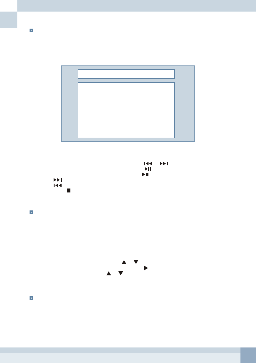
A
B
C
Menu bar
A :
Tool bar
B :
Monitor (Server) list window
C :
Media monitoring window
D :
Message monitoring window
E :
Log message window
F :
D E
F
[ Client S/W ]
26
Page 27

Description of tool bar
A B C D E F G H I J
Item Description
A
B Used to start and stop the monitoring of the media and the message schedule.
C Used to edit the media schedule.
D Used to edit the message schedule.
E Used to send media files to the monitor and to delete media files that are in the monitor.
F Used to change options of motion detection.
G Used to change the display mode or to change the main and the PIP video sources.
H Used to edit the Emergency message.
I
J Used to mute the sound of all actively connected monitors.
Used to add the new monitor or remove a monitor in the monitor list.
This is also used to establish network parameters.
When clicking this icon, the selected Emergency message of each monitor will be
displayed on the screen.
Network Setup
Establish network parameters to connect to monitors via an Ethernet connection.
Add and delete monitors connected via an Ethernet connection.
Click the Network icon to modify network
parameters.
Click the Add button to enter network
parameters for a new monitor connection.
Fill correct IP Address, Subnet Mask and
Gateway. Position is the name of the monitor that
is displayed in the Monitor List window.
Click the Save button.
27
Page 28

Connecting to the Monitor
To see the registered name (Position) of
monitor, double click MONITOR or click +
on the Monitor List window.
The monitor list disappears when you
double click MONITOR.
The upper window appears when you firstly open
the program.
Enter ID and Password and click the Submit button.
Right-click the name of the monitor.
Click Connect to connect to the monitor.
The other way to connect to the monitor,
is to double click the name of the monitor.
Right-click the name of the monitor and
then click Disconnect to disconnect the
monitor.
If connection is successful, the status of the
media and message schedule will be displayed.
28
Page 29

Time/Sync
Execute this option to synchronize time and the date of the monitor to the client computer.
Right-click the name of the monitor.
Click Time Sync.
Monitoring
This is a convenient feature when operating the monitor remotely.
By clicking the Monitoring icon, the media and message schedule will be displayed.
In addition the currently playing media file and message display is shown in the monitoring window.
The monitoring window also offers the option of starting and stopping the schedule.
Media Monitoring Window Message Monitoring
[ Monitoring Window ]
[ Media Monitoring ]
This window displays the list of media files
A :
that are registered.
If present, the Event option is marked by "o"
in the Event column.
The media file that has the blue bar is
currently displayed on the screen.
Used to start and stop the Media monitoring.
B :
Start Media Schedule before media can be
monitored.
Used to start and stop Media schedule.
C :
29
Page 30

A :
This window displays the list of Messages that
are registered.
If present, the Event option is marked by "o" in
the Event column.
The message that has the blue bar is currently
displayed on the screen.
Used to start and stop the Message monitoring.
B :
Start Message Schedule before the message
can be monitored.
Used to start and stop Message schedule.
[ Message Monitoring ]
C :
Media Schedule
The media files can be played on a specific date and during the specified time or the order that is listed in
the MEDIA window.
Edit options of the media file for the schedule before execution of this feature.
- Send media files to the monitor in advance to register it in Media schedule.
- Only one schedule file can be in the monitor.
Procedure of media schedule
- Click the Media icon.
- Add media files from the server window.
- Make the playlist and change options of each media file.
- Send the edited playlist (schedule) to the monitor.
The playlist will be saved in the monitor.
The monitor will play media files on the basis of schedule that is in the monitor.
- Wait for a minute and then click the Start button.
Refer to the followings to edit the playlist.
Click the Media icon.
You can see the right window.
The Schedule window indicates the playlist
of media files. The server window indicates
the storage devices that are connected to the
monitor. Contents of the specific foldercan
be seen by double clicking it.
Double click to go to the upper folder in
the server window.
Playlist (Schedule) window
Server window
30
Page 31

Select the folder that contains media files
to be registered for Media schedule.
Select one or more files in the server
window.
Drag selected files in the server window
and drop them in the schedule window.
Server Time
Indicates current time of the selected monitor.
File path
Indicates the file path.
Start time
Indicates time that playback of the media file starts.
Only applied when Play Type was set to Time or the
Event option was set to Time Event.
Stop time
Indicates time that playback of the media file is
terminated. Only applied when Play Type was set to
Time or the Event option was set to Time Event.
Care must be taken not to overlap playback
time between media files.
Event
Select the Event option to Time Event to play the media file from the Start time to Stop time.
Only time parameters are applied.
This option has the highest priority than other setups when you play media files.
The upper window will appear.
< Scheduling Setup Window >
Repeat
Repeat playback of the selected file as many as user setup.
(Only applied when Play Type was set to Sequence.)
31
Page 32

Select the Play Type option of Sequence or Time.
Time Options of each media file are not applied if the Play Type option was set to Sequence.
The order of the playlist can be modified by dragging a specific media file and dropping it at the position
to be relocated in the Playlist window.
Click the Send button to update schedule of the monitor.
You can see progress of schedule update.
Wait a minute and then click the Start button to play media files on the basis of schedule.
A: SEND :
B: Play Type :
This means that date option is ignored.
Year and month options are ignored.
Used to send the schedule information to the server.
START :
STOP :
ALL :
Open File :
to use it to other purposes. This button is used to open the Media Schedule file that is in your PC.
Save File :
The file extension is *.vsf.
Server File :
client software doesn’t know the schedule information.
Use this button to get the schedule information from the server.
* Sequence : Media files are played in the order that are listed in the playlist window.
* Time : Media files are played during the time that are matched to Time options.
Time Option
* Hour basis
* Day basis
* Week basis
* None
Modify :
Delete :
Used to play media files according to schedule that is in the monitor.
Used to stop Media schedule of the selected monitor.
Check this option to start or stop Media schedule of all monitors.
Schedule that was edited can be saved in your local PC to send it to other monitors or
This button is used to save edited Media Schedule in your PC.
When you connect the client software to the monitor via Ethernet for the first time, the
Defines how to play media files.
The media file is played during the time that is matched.
The media file that is matched to the date and time options is played.
The media file is played on the basis of week and time.
All parameters in Start time and Stop time are applied.
Used to modify playback options of the selected media file.
Remove the selected media file from the playlist.
C: Schedule File Transfer :
D: Playlist :
Display the list of media files for playback.
Indicates progress of schedule update.
32
Page 33

Message Schedule
Messages that are registered in the Schedule window can be displayed from the top message
to the bottom message or during setup time on the bottom of the screen.
The text font, size and color can be modified.
Only one schedule file can be in the monitor.
Procedure of Message schedule
- Click the Message icon.
- Type the message and add it to the Message list widow.
- Edit message schedule and change options of each message.
- Send edited schedule to the monitor.
The information of Message schedule will be saved in the monitor.
The monitor will display messages on the basis of schedule that is in the monitor.
- Wait for a minute and then click the Start button.
Refer to the following for information regarding the text display.
Click the Message icon.
The right window will appear.
[ Message List Window ]
Type the message and click the Insert
button to add it in the Message List window.
Up to 255 characters can be typed.
Message Schedule
Window
Message List
Window
Drag one or more messages in the Message
List window and drop them in the Schedule
window.
33
Page 34

Adjust options of each message for schedule.
Up to 40 messages can be registered.
Click the Save button.
Server Time
Indicates current time of the selected monitor.
Message
Indicates the message to be displayed.
The message can also be modified in this window.
Start time
Start time of text display.
Only applied when Play Type was set to Time or the Event option was set to Time Event.
Stop time
Stop time of text display.
Only applied when Play Type was set to Time or the Event option was set to Time Event.
Care must be taken not to overlap playback time between messages.
Event
Select the Event option to Time Event to play the message from the Start time to Stop time.
Only time parameters are applied.
This option has the highest priority than other setups when you display messages.
Speed
It indicates crawl speed of the message when Type is set to Flow.
When Type is set to Flash, this indicates flash speed of the message.
Type
It indicates how the message is displayed on the screen.
There are three options Normal, Flow and Flash.
- Normal : The message is still on the bottom of the screen.
- Flow : The message crawls from right to left on the bottom screen.
- Flash : The message flashes.
Font Size
Used to adjust the font size.
Font Color
Used to change the font color.
34
Page 35

Select the Play Type option of Sequence or Time.
Time options of each message are not applied when the Play Type option was set to Sequence.
The order of the message list can be modified by dragging a specific media file and dropping it at
the position to be relocated in the Message Schedule window.
Click the Send button to renew schedule information of the monitor.
You can see progress of schedule update.
Wait a minute and then click the Start button to display messages on the basis of schedule.
A: SEND :
is in your PC.
Used to send the schedule information to the server.
START :
STOP :
ALL :
This option is also used to start or stop Message schedule of all monitors.
Open File :
to use it to other purposes. This button is used to open the Message Schedule file that
Save File :
Server File :
client software doesn’t know the schedule information.
Use this button to get the schedule information from the server.
Used to display messages according to schedule that is in the monitor.
Used to stop Message Schedule of the selected monitor.
Check this option to send the schedule information to all servers.
Schedule that was edited can be saved in your local PC to send it to other monitors or
This button is used to save edited schedule in your PC. The file extension is *.msf.
When you connect the client software to the monitor via Ethernet for the first time, the
B: Play Type :
* Sequence : Messages are displayed in the order that are listed in the Message Schedule window.
* Time : Messages are displayed during the time that matched to Time options of each message.
Time Option
* Hour basis
* Day basis
The message that is matched to date and time options is displayed.
Year and month options are ignored.
* Week basis
The message is displayed on the basis of week and time.
* None
All parameters in Start time and Stop time are applied.
Insert :
Schedule window.
Modify :
Delete :
C: Schedule File Transfer :
D: Schedule :
Defines how to play media files.
The message is displayed during the time that is matched to Time options.
This means that date option is ignored.
Used to register the message selected in the Message List window to the Message
Used to modify schedule options of the selected message.
Remove the selected message in the Message Schedule window.
Indicates progress of schedule update.
Display the list of messages for schedule.
35
Page 36

File Transfer (Upload media files to the monitor)
You Media files must be uploaded to the monitor before the media schedule.
It is impossible to upload media files to the root path ( PATH=/ ).
Refer to the following to see how to transfer media files to the server.
Click the File Transfer icon.
< Server Window >
Storage devices that are connected to the
monitor will be displayed in the Server window.
Total capacity and usage of storage devices
is displayed in the server window.
Double click the folder to see its contents.
Double click the to go to the upper folder.
It is possible to delete media files and move
them to other folders in the Server window.
Server Window Client Window
You can see the contents in the client computer.
Double click the folder to see its contents.
Double click the to go to the upper folder.
Media schedule has to be renewed if you renamed any folder or moved media files to other folders.
It is highly recommended to do no other actions during the file transfer.
36
Page 37

Select one or more media files.
Right-click of media files and then click
Upload button to transfer media files to the
monitor. The other way to upload media files
to the server, drag media files from the
Client window and drop them in the Server
window.
The File Transfer window that indicates
progress of the file transfer will appear.
The File Transfer window disappears after
completion of the file transfer.
You can stop or restart the file transfer in the
File Transfer window by click of or .
To delete the file in the File Transfer window,
stop the transfer of media files and then select
one of media files in the File Transfer window.
Right-click the selected file and then click Delete.
Monitor Adjustment
Options of motion detection and display mode can be changed using the client software.
In this option volume adjustment of the internal speakers of the monitor is available.
Refer to following instructions to adjust the monitor.
Motion Setup
Click the Motion icon. Change options on the Motion window.
Click the Change button to apply the new setup.
37
Page 38

CAM 1 & CAM2 Enable
Used to activate the motion detection process of each camera.
CAM1 & CAM2 Sensitivity
Used to adjust the sensitivity of motion detection.
Capture Time
CAPTURE TIME is the interval that the motion detection is processed.
Dwell Time
Dwell Time is the time that the motion camera is display on the designated window.
Motion Start / Stop time
This option is used to set when the motion detection function is active.
Picture Full
The motion camera is displayed on full in the main window.
Display Setup
Click the Display icon. Change options on the Display window.
Click the Change button to apply the new setup.
MODE
Used to change the display mode.
MAIN Source
Used to select the main video source.
PIP Source
Used to select the PIP video source.
Reverse
Apply this option to display MEDIA for motion event display.
Cameras are motion event display when this option is not applied.
Volume mute
Apply this option to cut off the sound of the selected monitor.
Volume Control
Used to adjust the volume of the selected monitor.
38
Page 39

Emergency Message
An emergency message can be sent to all monitors in the same network.
The message also can be displayed with the audio file and the still image that were selected in the
Emergency Setup window.
Refer to following instructions to display the emergency message.
Click the Emergency Setup icon to display
the Emergency Setup window.
Click the Audio button to play an audio file
with the emergency message.
Type the message to be displayed.
Up to 255 characters can be typed.
Set Font color and other options in the Option box.
Click the New button to add the newly typed
message in the Emergency list.
The audio file has to be in the monitor to register
it with the message. So the audio file has to be
transferred to the monitor.
To transfer the audio file, click the Add button.
Select the folder where the audio file is
located. Choose the audio file that you
want to play and then click the Open
button. You can see progress of the audio
file transfer.
You can see the uploaded audio file.
Choose the audio file and then click the Select
button.
39
Page 40

The selected audio file name will be
seen on the Emergency Setup window.
Use the same procedure to add the
image file for display with Click the Save
button to save the modified message.
[ Emergency window – Detailed view ]
A: Monitor list
Indicates registered monitors.
B: Message list
Indicates messages that have been registered.
The selected message is marked by "o" in the column of Sel.
Select one of the messages.
Click the Start button to display the message
selected.
C: Font Size
Used to change the font size.
Message Type
Used to decide how to display the message on the screen.
You can select this option to Normal, Flow or Flash.
Font Color
Used to change the font color.
40
Page 41

Image Update (Company logo)
The background image can be seen when the Media is selected as the main or PIP video source.
The default background image of the monitor can be changed to other images.
But there are some restrictions.
Before Image Update, you have to stop playback of a media file.
Restrictions
File format : *.jpg
Image size
32" : 1280 x 720 (NTSC & PAL)
20.1" : 640 x 480 (NTSC)
720 x 576 (PAL)
Refer to following instructions to change the background image.
Right-click the server that you want to
update and then click Image Update.
Click the File Open button.
Click the Start button.
Select the folder where the image is located.
Choose the image to be updated and then
click the Open button.
You have to reboot the media system to see the newly updated image.
Right-click the server and then click Power / Reboot to reboot the Media system.
Wait Until the Update window disappears.
Reboot the Media system.
41
Page 42

Play Time
Used to decide how long the message is displayed on the screen.
0 : The message is displayed until the stop button or is clicked
SEND ALL MONITOR
The unregistered message that is written in the Message box can be displayed on the screen.
In this condition, only the message is displayed on the screen.
Set this option to send the message that is not registered to all monitors.
D: Audio & Image
Indicates the name of the audio and the Video files to be played on the screen with the message.
E: Message
Type the message in this box.
F: New
Used to register the newly typed message.
Save
Used to save the modified message.
Delete
Used to delete the message that is in the Message List box.
Clear
Used to clear all options and the message in the Message box.
It is convenient to make the new message.
Start
Used to start Emergency.
Stop
Used to stop Emergency.
Close
Used to close the Emergency Setup window.
Refer to the following step to send the unregistered message to the selected
monitor or all monitors.
1. Click the Emergency icon.
2. Select one of the messages in the Message List box.
3. Apply the option of Send All Monitor to send the message to all monitors in the LAN.
4. Clear the current message and Type the new message in the Message box.
The default setups are applied when you click the Clear button.
5. Click the Start button.
Click of will display the last selected emergency message of each monitor.
42
Page 43

Application Update
This program is located in the HDD.
This program can be easily updated using the client software.
The newly updated program will be applied after the reboot of the Media system.
File extension : *.pvm
It is recommended to stop Media and Message Schedules before update.
The update file has to be in your PC before Application Update.
Refer to following instructions to update the program.
Right-click the sever to be updated.
Select Program Update/Application.
Select the folder where the update file is
located.
Select the correct file and then click the
Open button.
Reboot the Media system.
Click the File open button.
Click Start.
Wait until the Update window disappears.
43
Page 44

System Update
This is renewal of contents of the flash memory.
The flash memory contains OS, drivers and others.
It takes about 3~4 minute to complete System update.
The newly updated software will be applied after the reboot of the Media system.
File extension : *.bin
Stop media and text Schedules before update.
The update file has to be in your PC before System update.
Refer to following instructions to update the program.
Right-click the monitor to be updated.
Select Program Update / System.
Select the folder where the update file is
located.
Select the correct file and then click the
Open button.
Reboot the Media system.
Click the File open button.
Click the Start button.
Wait until the Update window disappears.
44
Page 45

CHAPTER 6 - TROUBLESHOOTING
Screen is black and power indicator is green.
- Ensure that the power cord is firmly connected and the LCD monitor is on.
- Check PHOTO INPUT adjustment..
No Picture.
- Check the signal connections.
The image is too light or too dark.
- Adjust the Brightness and Contrast.
Picture is improperly tinted.
- Check color adjustment.
The monitor is inaccessible using Ethernet connection.
- Check the LAN cable is firmly connected to the monitor.
- Check your network environment.
- Check network parameters of the monitor are correct.
Media files upload fail.
- Check the LAN cable is firmly connected to the monitor.
- Check your network environment.
- Check network parameters of the monitor are correct.
Can not display messages.
- Check the message list is correctly made.
- Check the schedule type was set to Time basis.
- Check the background image is fit to recommended size.
Motion is not detected or detected too often.
- Adjust sensitivity of motion detection.
Remote control malfunctions.
- Check the battery terminals.
- Replace the remote control batteries.
No sound.
- Ensure that the audio cables are firmly connected to both the audio-in ports on your
monitor.
- Check the volume level.
45
Page 46

CHAPTER 7 - SPECIFICATION
Items
LCD
Video
HDD
Ethernet
USB
Playback
Camera
(Internal)
Light Sensor (Power save mode)
Text Overlay
Power Requirement
Power Consumption
Operating Temperature
Storage Temperature
Dimension
Weight
Accessories
Size
Pixel Format
Brightness (Typical)
Contrast Ratio (Typical)
Viewing Angle H/V
Color Depth
Light Source / Lifetime
Response Time (Typical)
System
Composite
S-Video
Component
PC (Analog)
PC (DVI)
Audio
USB 2.0 Host
USB 2.0 Device
Video Decoding
Audio Decoding
No. of Camera
CCD
Resolution
Sensitivity
S/N Ratio
Auto Iris
AWB
Electronic Shutter
VF Lens
WDR
Level
Input
Output
Connector
Level
Connector
Mode
Signal
Level
Connector
Mode
Signal
Level
Connector
Plug & Play
Mode
Connector
Plug & Play
Level
Input
Output
Amplifier
32.0 inch PVM Pro 20.1 inch PVM Pro
32 inch
1366 x 768 x RGB
500 cd/m2
1200 : 1
178 / 178
8bit / 16.7M Colors
16 CCFLs / 50,000 Hrs
8 ms (Gray to Gray)
NTSC / PAL
1Vp-p @ 75 ohm
Internal Camera x 1
External Camera x 2
Internal Camera x 1
External Camera x 2
BNC
1Vp-p (L), 0.3(C)Vp-p @ 75ohm
4pin Mini-DIN X 1
1080i, 720p, 480p, 480i
YPbPr (SOY)
1Vp-p(Y), 0.3Vp-p(Pb & Pr) @ 75 ohm
3-terminal RCA x 1
1366 x 768 @ 75Hz Max
Analog RGB & H/V Sync.
0.715Vp-p (RGB) & TTL (Sync.)
15 Pin D-SUB
DDC 2B
1366 x 768 @ 75Hz Max
DVI-I
DDC 2B
Line Level
2-Terminal RCA x 2
Phone Jack x 1
5W x 2
40GB x 1
RJ45 x 1
x 1
x 1
MPEG-1, MPEG-2 MP@HL
MPEG-4.2 ASP@L5(720p), WMV9
JPEG
MPEG-1 Layers 1, II and III,
MPEG-4 Low Complexity AAC
1
1/3"
480 TVL
1 Lux ( F2.0, 50 IRE )
50 dB
Yes
Yes
1/60 ~ 1/100,000
1/50 ~ 1/100,000
4 - 9 mm ( F2.0 ~ 2.8 )
Option
Yes
Yes
AC 100 ~ 240V ( 50/60 Hz)
200 W
O
5 ~ 40 C
O
0 ~ 50 C
796.50mm x 592.00mm x 108.25mm (Net)
915.0mm x 715.0mm x 270.0mm (Packing)
22.5 kg (Net)
28 kg (Packing)
Manual, Remote Control, Client S/W, VGA Cable
DVI Cable, USB Cable, Power Cord
20.1 inches
640 x 480 x RGB
450 cd/m2
800 : 1
178 / 178
8bit / 16.7M Colors
CCFL / 50,000 Hrs
25 ms (Rise + Decay time)
NTSC / PAL
1Vp-p @ 75 ohm
Internal Camera x 1
External Camera x 2
Internal Camera x 1
External Camera x 2
BNC
1Vp-p (L), 0.3(C)Vp-p @ 75ohm
4pin Mini-DIN X 1
--
--
--
--
--
--
--
--
--
--
--
--
Line Level
2-Terminal RCA x 1
Phone Jack x 1
5W x 2
40GB x 1
RJ45 x 1
x 1
x 1
MPEG-1, MPEG-2 MP@HL
MPEG-4.2 ASP@L5(720p), WMV9
JPEG
MPEG-1 Layers 1, II and III,
MPEG-4 Low Complexity AAC
1
1/3"
480 TVL
1 Lux ( F2.0, 50 IRE )
50 dB
Yes
Yes
1/60 ~ 1/100,000
1/50 ~ 1/100,000
4 - 9 mm ( F2.0 ~ 2.8 )
Option
Yes
Yes
DC 12V / 6.2A
75 W
O
5 ~ 40 C
O
0 ~ 50 C
472.40mm x 459.40mm x 101.31mm (Net)
640.0mm x 540.0mm x 190.0mm (Packing)
10.5 kg (Net)
14.5 kg (Packing)
Manual, Remote Control, Client S/W, Adaptor
USB Cable, Power Cord
46
Page 47

20.1_32.0 Inch PVMpro
PRINTED IN KOREA
Instruction and Operation
M A N U A L
05504589A
 Loading...