

Page 1
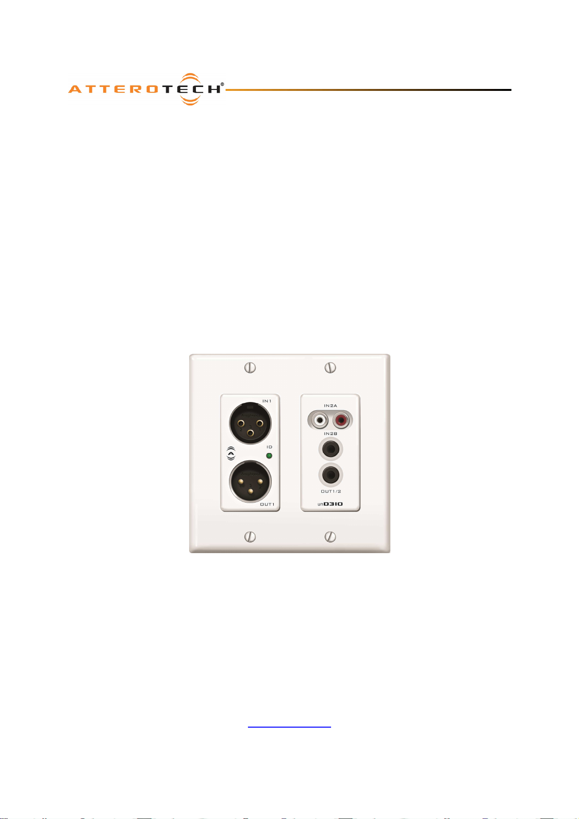
unD3IO
User Manual
unD3IO
2-in/2-out Dante Wallplate with Multi-IO Analog
Connectivity
User Manual
1315 Directors Row, Suite 107, Ft Wayne, IN 46808
Phone 260-496-9668 • Fax 260-496-9879
Date 05/22/2014
Revision 01
Attero Tech, LLC
www.atterotech.com
614-00017-01
Page 2

unD3IO
User Manual
IMPORTANT SAFETY INSTRUCTIONS
The symbols below are internationally accepted symbols that warn of potential hazards with electrical products.
This symbol, wherever it appears, alerts you to the presence of un-insulated dangerous voltage inside the
enclosure -- voltage that may be sufficient to constitute a risk of shock.
This symbol, wherever it appears, alerts you to important operating and maintenance instructions in the
accompanying literature. Please read the manual.
1. Read these instructions.
2. Keep these instructions.
3. Heed all warnings.
4. Follow all instructions.
5. Do not use this apparatus near water.
6. Clean only with a dry cloth.
7. Do not block any ventilation openings. Install in accordance with the manufacturer's instructions.
8. Do not install near any heat sources such as radiators, heat registers, stoves, or other apparatus (including
amplifiers) that produce heat.
9. Do not defeat the safety purpose of the polarized or grounding-type plug. A polarized plug has two blades
with one wider than the other. A grounding type plug has two blades and third grounding prong. The wider
blade or the third prong is provided for your safety. If the provided plug does not fit into your outlet, consult
an electrician for replacement of the obsolete outlet.
10. Protect the power cord from being walked on or pinched particularly at plugs, convenience receptacles, and
the point where they exit from the apparatus.
11. Only use attachments/accessories specified by Attero Tech
12. Use only with the cart, stand, tripod, bracket, or table specified by the manufacturer, or sold with the
apparatus.
13. When a cart is used, use caution when moving the cart/apparatus combination to avoid injury from tip-over.
14. Unplug this apparatus during lightning storms or when unused for long periods of time.
15. Refer all servicing to qualified service personnel. Servicing is required when the apparatus has been damaged
in any way, such as power-supply cord or plug is damaged, liquid has been spilled or objects have fallen into
the apparatus, the apparatus has been exposed to rain or moisture, does not operate normally, or has been
dropped.
16. This apparatus shall be connected to a mains socket outlet with a protective earthing connection.
17. When permanently connected, on all-pole mains switch with a contact separation of at least 3mm in each pole
shall be incorporated in the electrical installation of the building.
18. If rack mounting, provide adequate ventilation. Equipment may be located above or below this apparatus but
some equipment (like large power amplifiers) may cause an unacceptable amount of hum of may generate too
much heat and degrade the performance of this apparatus,
TO REDUCE THE RISK OF FIRE OR ELECTRIC SHOCK, DO NOT EXPOSE THIS APPARATUS TO RAIN OR MOISTURE.
Attero Tech LLC 2014 Page 1 614-00017-01
Page 3

unD3IO
User Manual
LIMITED TWO YEAR WARRANTY
The equipment is warranted for two year from date of purchase from Attero Tech, LLC against defects in materials or
workmanship. This warranty does not cover equipment which has been abused or damaged by careless handling or
shipping. This warranty does not apply to used or demonstrator equipment. Should any defect develop, Attero Tech,
LLC will, at our option, repair or replace any defective parts without charge for either parts or labor. If Attero Tech, LLC
cannot correct the defect in the equipment, it will be replaced at no charge with a similar new item. Attero Tech, LLC
will pay for the cost of returning your equipment to you. This warranty applies only to items returned to Attero Tech,
LLC, shipping costs prepaid, within two year from the date of purchase. This Limited Warranty is governed by the laws
of the State of Indiana. It states the entire liability of Attero Tech, LLC and the entire remedy of the purchaser for any
breach of warranty as outlined above. NEITHER ATTERO TECH, LLC NOR ANYONE INVOLVED IN THE PRODUCTION OR
DELIVERY OF THE EQUIPMENT SHALL BE LIABLE FOR ANY INDIRECT, SPECIAL, PUNITIVE, CONSEQUENTIAL, OR
INCIDENTAL DAMAGES ARISING OUT OF THE USE OR INABILITY TO USE THIS EQUIPMENT EVEN IF ATTERO TECH, LLC HAS
BEEN ADVISED OF THE POSSIBILITY OF SUCH DAMAGES. IN NO EVENT SHALL THE LIABILITY OF ATTERO TECH, LLC
EXCEED THE PURCHASE PRICE OF ANY DEFECTIVE EQUIPMENT.
This warranty gives you specific legal rights. You may have additional legal rights which vary from state to state.
Note: This equipment has been tested and found to comply with the limits for a Class A
digital device, pursuant to Part 15 of the FCC Rules and EN55022. These limits are
designed to provide reasonable protection against harmful interference when the
equipment is operated in a commercial environment. This equipment generates, uses,
and can radiate radio frequency energy and, if not installed and used in accordance with
the instruction manual, may cause harmful interference to radio communications.
Operation of this equipment in a residential area is likely to cause harmful interference,
in which case the user will be required to correct the interference at his own expense.
Attero Tech LLC 2014 Page 2 614-00017-01
Page 4

unD3IO
User Manual
Contents
1 - Overview .....................................................................................................................................................................................................................4
1.1 – What’s in the Box ..................................................................................................................................................... 4
2 – Device Installation.................................................................................................................................................................................................5
2.1 – Mounting .................................................................................................................................................................. 6
2.2 – Hardware Connections............................................................................................................................................. 6
2.2.1 – Balanced Source to Balanced Sink.................................................................................................................... 6
2.2.2 – Unbalanced Source to Balanced Sink ............................................................................................................... 6
2.2.3 – Balanced Source to Unbalanced Sink ............................................................................................................... 7
2.2.4 – Unbalanced Output to an Unbalanced Sink ..................................................................................................... 7
3 – Device Configuration ...........................................................................................................................................................................................8
3.1 – Software Installation................................................................................................................................................. 8
3.2 – Device Configuration.............................................................................................................................................. 10
3.2.1 – Selecting a Network Adapter ......................................................................................................................... 10
3.2.2 – Connecting to a Device.................................................................................................................................. 10
3.2.3 – Device Identification ...................................................................................................................................... 10
3.2.4 – Device Controls.............................................................................................................................................. 11
3.2.5 – Saving and Loading Settings.......................................................................................................................... 11
3.2.5.1 – Internal Presets ...................................................................................................................................... 11
3.2.5.2 – Preset Files............................................................................................................................................. 11
4 – ARCHITECTS & ENGINEERS SPECIFICATION ........................................................................................................................................ 12
4.1 – Device Specifications.............................................................................................................................................. 12
APPENDIX A - Reference Documents................................................................................................................................................................A-1
Attero Tech LLC 2014 Page 3 614-00017-01
Page 5
unD3IO
User Manual
1 - Overview
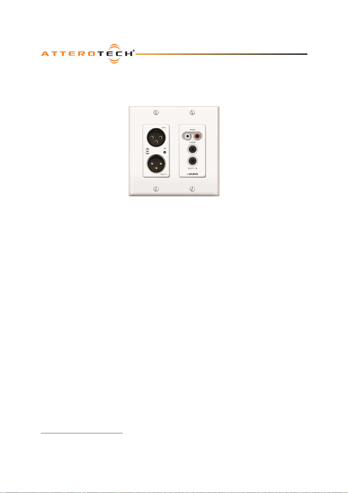
The unD3IO Dante Audio interface is a cost effective multi-IO wall box and is designed to fit into most dual gang US
junction boxes. Its size and I/O density make it easy to put Dante connectivity wherever it’s needed – near the audio
source or sink – thereby eliminating costly and interference prone analog wiring.
Figure 1 - unD3IO front view
The unD3IO features two Dante input and two Dante output channels. The analog I/O are configurable via software to
support different connectivity configurations. The XLR connector provides balanced mic/line audio to Dante output
channel 1. However, the second Dante output comes from one of three possible input mixes:
o A mono mix of the RCA jack inputs
o A mono-mix of the 3.5mm stereo jack inputs
o A combined mix of the RCA inputs and the stereo jack inputs
The user can select which mix they require through the control software.
The unD3IO has two output options. An XLR connector provides a balanced line output for analog output 1 only, and a
3.5mm stereo jack connector provides an unbalanced line level output for both analog output 1 and analog output 2.
Both output connectors may be used simultaneously.
Connection to the Dante network is provided by a single Ethernet RJ45 connector on the back of the unit. The unD3IO
is PoE-enabled which allows it to be powered over its network cable from a suitable PoE source (IEEE 802.3af-compliant)
and eliminating the need for a local power supply. This is particularly useful as the unD3IO can then be mounted in
remote locations where access to a mains outlet would be limited or indeed, non existent.
Audinate’s Dante Controller or other 3rd party manufacturer's Dante routing software can be used to control the audio
routing configuration of the device while the Attero Tech unIFY Control Panel application can be used to configure the
device-specific features such as the mic/line gain options, phantom power setup for the XLR input, and the input
selection for the unbalanced inputs.
1.1– What’s in the Box
The unD3IO comes supplied with the following
o unD3IO device
o Mounting kit
o Decora plate
Dante is a trademark of Audinate Pty. Ltd.
Attero Tech LLC 2014 Page 4 614-00017-01
Page 6
unD3IO
User Manual
2 – Device Installation
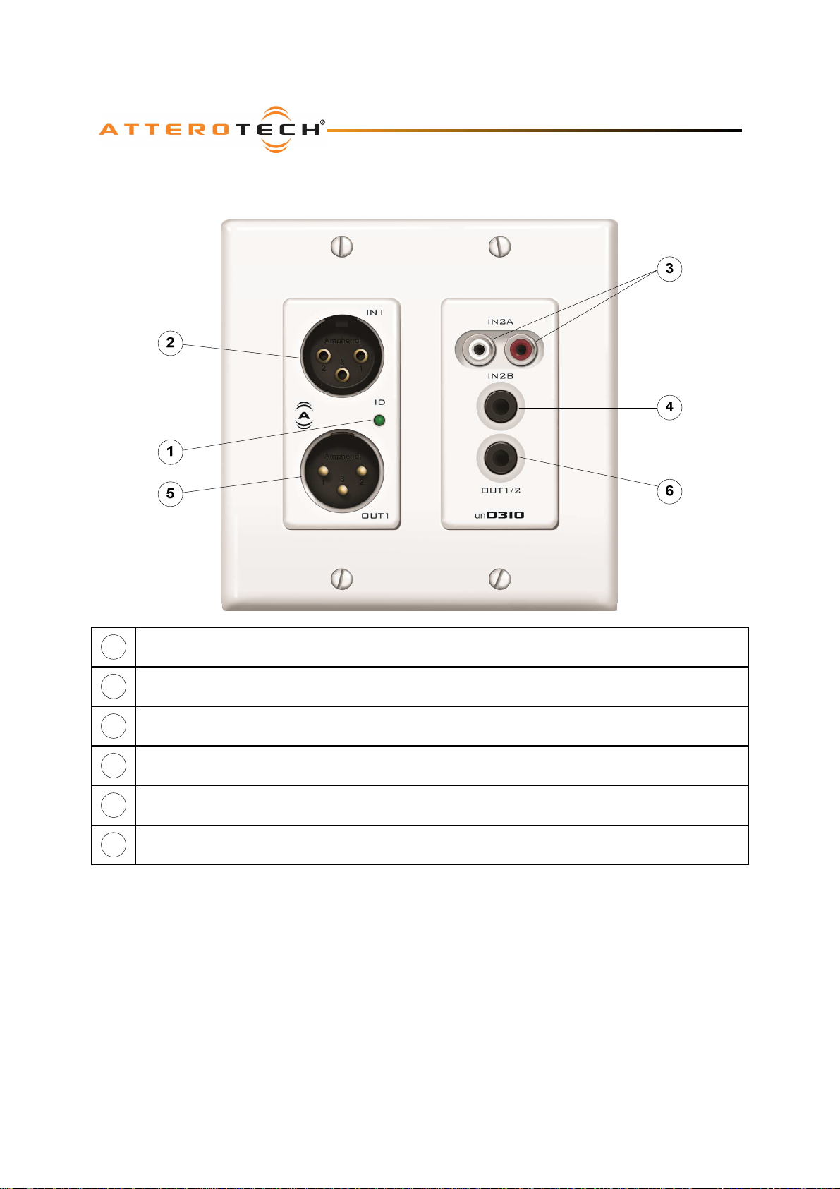
1
Power/ ID LED
Balanced audio input (Input 1)
2
3
Unbalanced RCA Audio inputs (Input 2A)
4
Unbalanced stereo 3.5mm jack audio input (Input 2B)
5
Balanced audio output (Output 1)
6
Unbalanced stereo jack audio output (Output 1 & 2)
*Note: The unD3IO has a label on the front of the metal housing at the top that shows the last 6 digits of the MAC
address. This is important for initial device identification as these digits make up part of the devices default network
name that is shown when the device is detected by Dante Controller. The full MAC address is also given on the back of
the unit.
Attero Tech LLC 2014 Page 5 614-00017-01
Page 7
unD3IO
User Manual
2.1 – Mounting
A typical installation will involve mounting the wall plate into the wall using an “old-work” type bracket or a premounted wall box. Before starting, make sure the wall box where the unD3IO is to be installed is pre-wired with a
suitable cable back to a PoE enabled network switch or mid-span injector. If a mid-span injector is being used, the
cable should be connected to the port that supplies both Ethernet and power (refer to the manual for the midspan
injector if unsure which port is which).
Attach the network cable from the switch/mid-span injector to the Dante I/F port of the Dante unD3IO. If the switch or
mid-span injector is already running and PoE is enabled, the unit should power up and the green ID LED on the front of
the device should turn on.
With the cable attached, carefully place the unD3IO into the wall box taking care to not trap the cabling. Once fully in
place, secure with the screws provided. Once the unit is secured in the wall box, fit the Decora plate and secure it with
the screws provided with it.
2.2 – Hardware Connections
The unD3IO accepts and drives either unbalanced or balanced audio devices. Refer to the following diagrams and
instructions for connecting different types of audio devices. Professional grade audio cabling is recommended to
achieve the best audio performance throughout the system.
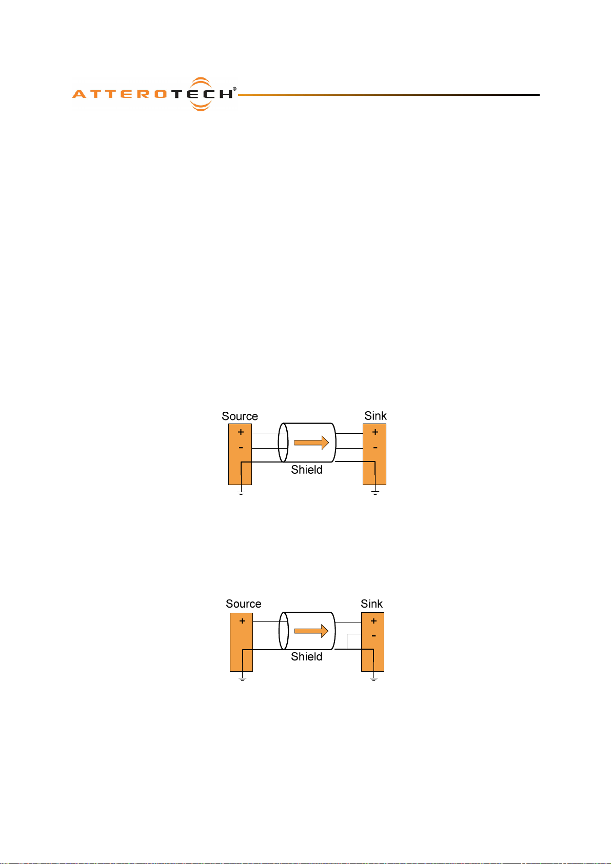
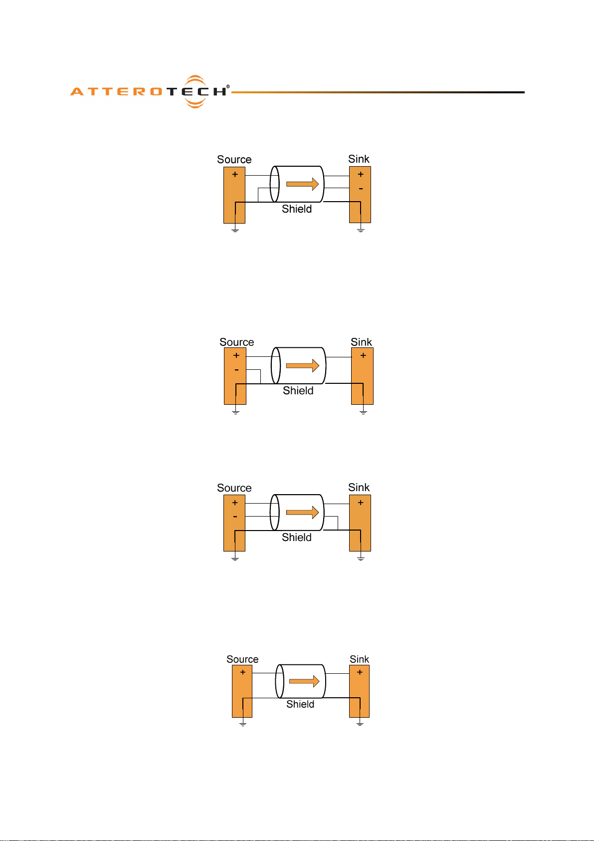
2.2.1– Balanced Source to Balanced Sink
To connect balanced sources to the unD3IO XLR input or connecting a balanced sink to the unD3IO XLR output, use a 2core cable with a shield and connect positive output to positive input, and negative output to negative input using the
cable cores, and connect output ground to input ground using the cables shield.
Figure 2 - Balanced Source to Balanced Sink Connection
2.2.2 – Unbalanced Source to Balanced Sink
Use the following if using a single core cable with shield to connect a 2-wire unbalanced source to XLR input on the
unD3IO, or to connect an RCA or stereo jack unbalanced output signal from the unD3IO to a balanced input on another
device. Connect the positive output of the unbalanced source to the positive input of the balanced sink. Connect both
the source and sink input grounds together and short the negative input of the sink to ground at the input of the sink.
Figure 3 - 2-Wire Unbalanced Source to Unbalanced Sink Connection
Attero Tech LLC 2014 Page 6 614-00017-01
Page 8
unD3IO
User Manual
For the same connections but using a 2-core + shield cable, connect the positive and grounds as before but this time,
short the negative conductor to the shield at the source connection instead.
Figure 4 - 3-Wire Unbalanced Source to Balanced Sink Connection
2.2.3 – Balanced Source to Unbalanced Sink
Use the following if using a single core cable with shield to connect a balanced source to an RCA or stereo jack input on
the unD3IO or to connect the XLR output from the unD3IO to an unbalanced input on another device. Connect the
positive output of the balanced source to the positive input of the unbalanced sink. Connect both the source and sink
input grounds together and short the negative input of the source to ground at the output of the source.
Figure 5 - 3-Wire Balanced Source to Unbalanced Sink Connection
For the same connections but using a 2-core + shield cable, connect the positive and grounds as before but instead,
short the negative conductor to the shield at the sink end of the cable instead.
Figure 6 - 3-Wire Balanced Source to Unbalanced Sink Connection
2.2.4 – Unbalanced Output to an Unbalanced Sink
To connect an unbalanced source to unD3IO RCA or stereo jack input, or connect the stereo jack output to an
unbalanced sink, connect the positive output to the sink’s positive input and connect the grounds together through the
cable shield.
Figure 7 – Unbalanced Source to Unbalanced Sink Connection
Attero Tech LLC 2014 Page 7 614-00017-01
Page 9
unD3IO
User Manual
3 – Device Configuration
There are two parts of the device that require software to setup. First the audio routing, and second the configurable
features of the device itself.
The audio routing should be carried out using any application that supports Dante audio routing. This could be from a
3rd party manufacturer or be Audinate’s own Dante Controller. Dante Controller can be obtained from the Audinate
website (www.Audinate.com). Instructions on how to use this software and about setting up routes on a Dante network
can also be found on Audinate’s website.
*Note: When using Dante controller, the unD3IO will be shown using a default device name of unD3IO-###### where
‘######’ is the last six characters of the devices MAC address.
Configuration of the unD3IO specific features is carried out using the Attero Tech unIFY Control Panel application. This
application is available from the Attero Tech website (www.atterotech.com). It is used to initially configure the device
and can examine and modify the device specific features such as mic/line gain settings, phantom power, and output
boost options. The unD3IO features are supported in unIFY Control Panel V1.3 or later.
The unD3IO also supports 3rd party control systems by configuration with direct UDP messages. Further information on
using this facility can be found in the unIFY 3rd Party Control – Software API document available from the Attero Tech
website.
3.1 – Software Installation
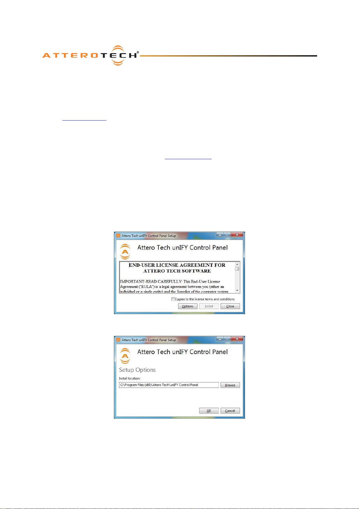
After downloading the application, run the .exe and the first screen to appear will be the license agreement and options
screen.
The software will install to a default location of c:\program Files (x86)\Attero Tech\unIFY Control Panel). Clicking the
“Options” button allows the user to change the installation location if required though it’s not necessary to change it.
To continue the install, read the license agreement and check the “I agree…” check box. Doing so enables the “Install”
button. Click the now enabled “Install” button to start the transfer of files.
Attero Tech LLC 2014 Page 8 614-00017-01
Page 10
unD3IO
User Manual
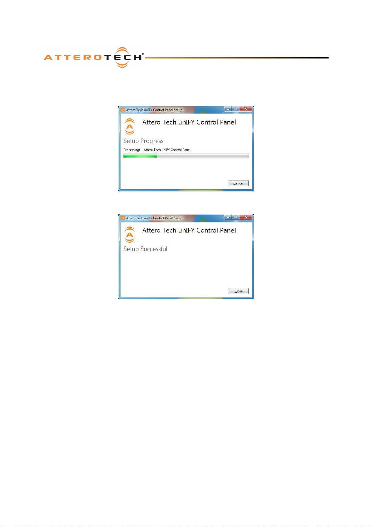
On Windows Vista or later if the PC has the UAC enabled, a warning pop up will now appear saying the installer is about
to make changes to your PC. This needs to be accepted for the installation to complete successfully.
The installer will show a progress screen and will now being transferring files to your PC
Once the files are transferred, the installer will show a completion message show whether the installation was
successful or not.
If the installation was unsuccessful for any reason, the final screen will show an error message.
Attero Tech LLC 2014 Page 9 614-00017-01
Page 11
unD3IO
User Manual
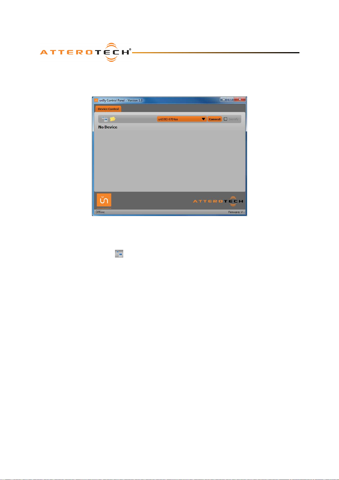
3.2 – Device Configuration
Once the required software is installed, click on the unIFY Control Panel icon in the programs list under Attero Tech.
This will start the application.
Figure 8 - Device Configuration window
3.2.1 – Selecting a Network Adapter
In order to connect to a device the application needs to know what network adapter it should use to contact devices.
Clicking on the networked PC icon will show a list of all possible adapters.
*Note: Only network adapters that are deemed as being compatible with Dante will be shown in the list.
3.2.2 – Connecting to a Device
A few seconds after selecting the adapter, the device list should start to populate with detected devices. The detected
devices are listed by their device name. Select the device to be configured from the drop down list and then click the
“Connect” button. The application will then attempt to establish a connection with the device. If successful, the status
bar will show “Connected” and the controls will become active and their values will update to show the current state of
the device including channel names (shown for each input and output in a small grey window just below the main
settings).
*Note: The channel name cannot currently be set from within the unIFY application. To change the channel names, use
Dante Controller.
This connected device is now treated as the active device and any changes to the controls will be sent to this device
alone.
3.2.3 – Device Identification
The device identification feature allows the user to see which device is physically being configured. When the Identify
feature is active, the power LED on the active device will flash. The Identify check box shows the state of the device
identify feature. If the box is checked, the feature is active on the active unit. If the check box is clear, the identify
feature is inactive. To change the state of the feature, simply click in the Identify check box to toggle its state from off
to on or on to off. The identify function will continue to operate until the function is turned off via the user interface or
the device is powered down.
*Note: The identify function of Dante Controller does not control the identify feature on the unD3IO. To identify a
device use the unIFY Control Panel identify function instead.
Attero Tech LLC 2014 Page 10 614-00017-01
Page 12
unD3IO
User Manual
3.2.4 – Device Controls
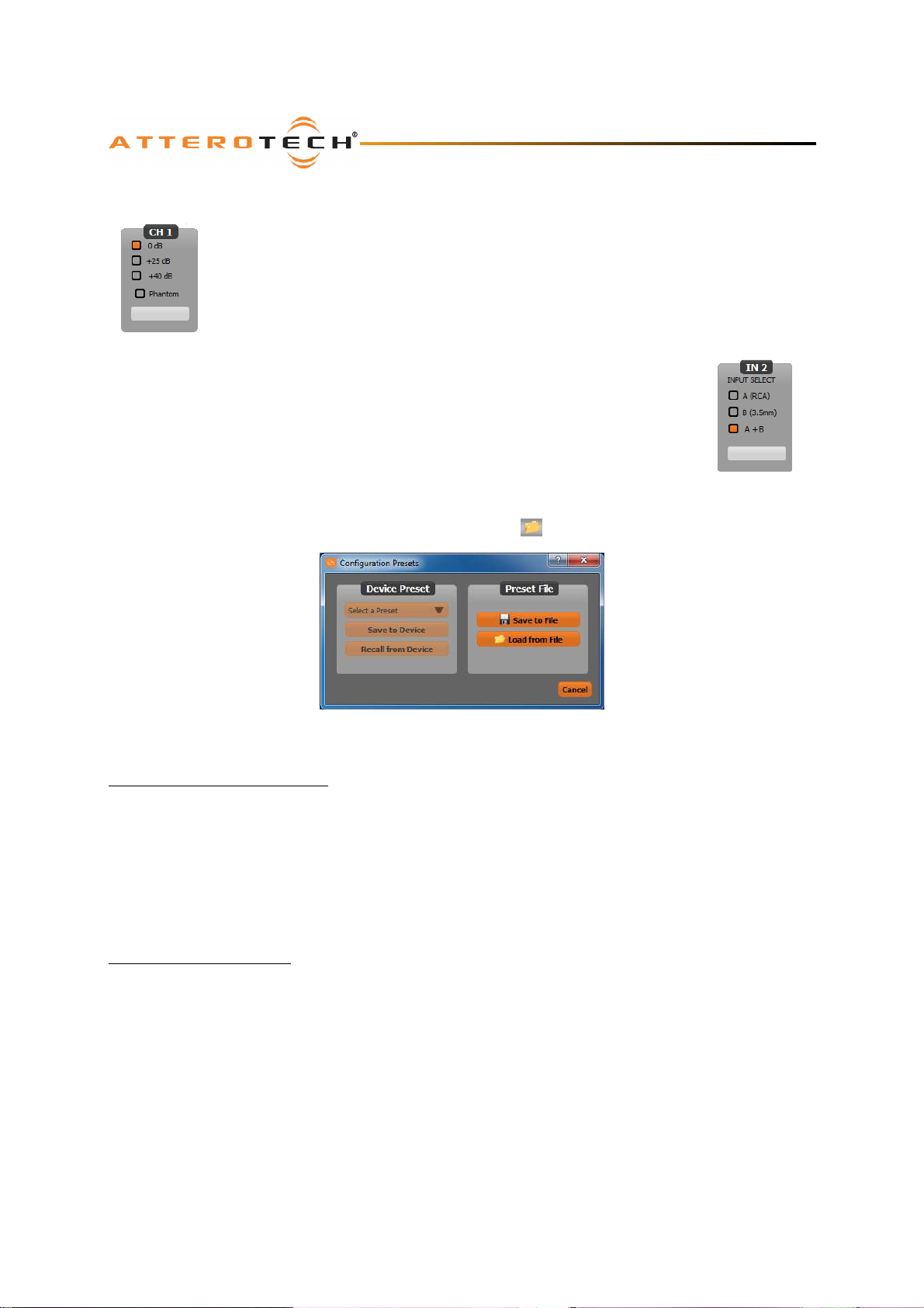
Each of the unD3IO inputs has different configurable options. The balanced input on the XLR (IN 1)
has mic/line gain options, and the phantom power control. The unbalanced outputs are fed into IN2
and the user has an Input Select option to determine audio from which unbalanced connector is
used.
The mic/line gain control gives the user three gain choices depending on the type of signal being
provided to the input. For a line level signal, select the 0dB option. The remaining two options are
for use if a microphone is to be connected directly to the input. If using a microphone as an input
The phantom power option is available for microphones that need it. The unD3IO provides 24V
phantom power. Check the box to turn phantom power on. Uncheck the box to turn it off.
The input selection option (shown right) allows the user to select which of the unbalanced inputs
are used as the second Dante output channel. Both RCA inputs are mixed by default to create
input source A. The 3.5mm stereo jack stereo inputs are mixed together to produce stereo source
B. The user can select which one of these sources the second input should be taken. The options
are source A only, source B only, or a mix of both source A and source B.
3.2.5 – Saving and Loading Settings
The unD3IO device settings can be saved or loaded by clicking on the icon to bring up the preset form.
source, choose the gain value that best suits the microphones output signal.
The unD3IO supports 9 internal presets with one of those presets used as the power-up default. It also supports saving
settings to, and loading settings from, a file for transferring to another device or backup purposes.
3.2.5.1 – Internal Presets
Settings in a device can be saved to an internal preset which can then be recalled at a later date. There are 9 internal
presets, one of which is the “Default” preset that is used to set device settings when the unD3IO is first powered on.
Select a preset to use by using the drop down in the Device Preset section. Once a preset has been selected, the
current settings of the device can be saved to the selected preset by clicking the “Save to Device” button. Alternately,
the settings from the selected preset can be loaded and used as the current settings by clicking the “Recall from Device”
button.
*Note: Loading a preset will overwrite all the current settings in the device with settings from the selected preset. The
GUI will also update to show these new settings overwriting all of its settings also.
3.2.5.2 – Preset Files
To allow settings to be transferred to others devices or for use as a backup, the current settings can also be saved to a
file or loaded from a file. When loading settings from a file, both the on-screen controls and the device settings will be
modified to match the settings from the file. If the settings from the file need to be saved to a preset, then that will
need to be done manually once the settings are loaded.
To save the current settings to a file, click the “Save to File” button and then enter an appropriate filename. To load
settings from a file, click the “Load from File” button and select the appropriate file.
Attero Tech LLC 2014 Page 11 614-00017-01
Page 13
unD3IO
User Manual
4 – ARCHITECTS & ENGINEERS SPECIFICATION
The Dante interface unit shall provide one mic/line analog input on the front panel with a female XLR connector.
Selectable gains of 0dB, +25dB, and +40dB, and +48V phantom power option shall be provided via software for the XLR
input. The unit shall provide one line level balanced output with a male XLR connector. The unit will provide two RCA
line level inputs and one 3.5mm TRS line level input, both internally summed to mono. The unit will provide a 3.5mm
TRS line level output. The internal analog to digital signal conversion shall be performed at 24-bit resolution with a
sampling frequency of 48kHz. The Dante interface unit shall receive power over the Ethernet cable from an 802.3af PoE
compliant network switch. The Dante interface shall be wall mounted in a standard US dual gang junction box.
The Dante interface shall be compatible with Attero Tech Unify software for flexible control and monitoring in system
applications. The Dante interface shall be compliant with the RoHS directive. The Dante interface unit shall be
compliant with the EMI/EMC requirements for FCC and CE.
The Dante interface shall be the Attero Tech unD3IO.
4.1 – Device Specifications
Audio Inputs (XLR):
Input Type:
Gain:
Maximum Input
Levels:
Phantom Power: +48V, software selectable
Input Impedance:
Audio Inputs (RCA, Jack):
Input Type:
Audio Outputs (XLR):
Output Type (XLR):
Maximum output
level:
Audio Outputs (Jack):
Output Type (Jack):
Maximum output
level:
Audio Performance:
Frequency Response: +/- 1dB, 20Hz – 20kHz
Noise: <-90dBu @ 0dB gain
System THD:
Balanced and RF filtered 3pin depluggable
0dB, +25dB, +40dB,
software selectable
+12dBu @ 0dB gain
-12dBu @ +25dB gain
-27dBu @ +40dB gain
>1.8K ohms at any gain
setting
Unbalanced RF filtered line
level stereo, each summed
to mono
Balanced line level with
automatic muting on loss
of Dante signal
+11.4dBu
Unbalanced line level with
automatic muting on loss
of Dante signal
+12.1dBu
<0.01% at any gain, input
signal 3dB below
maximum
Dante Network:
Physical Level: Standard Ethernet
Connector: Single RJ-45
Cable Quality: CAT-5
Transmission
Speed:
Power Requirements
Power Consumption
Dimensions
Operating
Temperature:
Compliance
100Mbps
IEEE802.3af PoE
Less than 3W
2.75”H x 3.60”W x 1.88”D
0 OC – 40 OC
FCC Part 15 Class A
CE (EN60960 and
EN55022 Class A)
RoHS
Attero Tech LLC 2014 Page 12 614-00017-01
Page 14

unD3IO
User Manual
APPENDIX A - Reference Documents
The following table lists the relevant reference documents.
Document Title Revision
unIFy 3rd Party Control – Software API 01
Attero Tech LLC 2014 Page A-1 614-00017-01
 Loading...