

Page 1
Control Center
Control for CobraNet Devices
User Manual
1315 Directors Row, Suite 107, Ft Wayne, IN 46808
Phone 260-496-9668 • Fax 260-496-9879
Date 07/15/2013
Revision 07
Attero Tech, LLC
614-00002-07
Page 2

Control Center
User Manual
Contents
1 – Overview ..............................................................................................................................................................................................................................1
1.1 – How to Use Attero Tech’s Control Center .......................................................................................................................1
2 – Installing the Software..................................................................................................................................................................................................2
2.1 – PC Requirements..............................................................................................................................................................2
2.2 – Installation Method..........................................................................................................................................................2
3 – Running the Application ..............................................................................................................................................................................................4
3.1 – Setting up the PC Network Adapter.................................................................................................................................4
3.2 – The Main Form.................................................................................................................................................................5
3.3 – Configuring the Mode of Operation ................................................................................................................................5
3.3.1 – Setting up Demo mode...........................................................................................................................................6
3.3.2 – Setting up Normal mode ........................................................................................................................................6
3.3.2.1 – IP Auto Assignment .....................................................................................................................................7
3.3.2.2 – IP address Range..........................................................................................................................................7
3.4 – Main Form Functions .......................................................................................................................................................8
3.4.1 – Setting a Devices IP Address ..................................................................................................................................9
3.4.2 – Using Static IP Addresses .......................................................................................................................................9
3.4.3 – Setting the Static Subnet Mask...............................................................................................................................9
3.4.4 – Configuring System Parameters...........................................................................................................................10
3.4.5 – Configuring the Serial Bridge...............................................................................................................................10
3.4.6 – Device Firmware Update.......................................................................................................................................11
3.4.7 – About ....................................................................................................................................................................11
4 – Bundles ..............................................................................................................................................................................................................................12
4.1 – Bundle Setup ..................................................................................................................................................................12
4.2 – Transmit Bundles..........................................................................................................................................................13
4.2.1 – Notes on Transmit Bundles ..................................................................................................................................14
4.3 – Receiver Setup................................................................................................................................................................15
4.3.1 – Notes on Receive Bundles ....................................................................................................................................16
4.4 – Mode Rate Control .........................................................................................................................................................16
5 – MatchBox Controls.......................................................................................................................................................................................................17
5.1 – MatchBox Device Configuration ....................................................................................................................................17
5.2 – MatchBox Monitor..........................................................................................................................................................17
6 – Device Setup for Attero Tech Devices................................................................................................................................................................18
7 – Troubleshooting............................................................................................................................................................................................................19
7.1 – Network Setup................................................................................................................................................................19
7.2 – Possible Issues...............................................................................................................................................................19
APPENDIX A – Introduction to CobraNet.................................................................................................................................................................A-1
APPENDIX B – Reference Documents.........................................................................................................................................................................B-1
Attero Tech LLC 2013 Page i 614-00002-07
Page 3

Control Center
User Manual
1 – Overview
Attero Tech Control Center is an easy to use configuration and monitoring application for CobraNet devices. As well as
being usable for configuring the generic parameters of any CobraNet device, such as the bundle setup for audio routing or
serial bridge functionality, it also includes device specific setup for Attero Tech products such as the VoiceBox 4 I/O and the
InBox and OutBox products.
*Note: Whilst devices from manufacturers other than Attero Tech are detected and displayed, use the manufacturers’ own
software to set up their devices. Using Control Center to control a device from another manufacturer is at the user’s own
risk. Attero Tech bears no responsibility for the results if settings are altered on a non-Attero Tech CobraNet device.
1.1 – How to Use Attero Tech’s Control Center
This manual is designed to give the user a guide on how to use the Attero Tech Control Center to view and control CobraNet
devices on a network. The steps required to use the software are as follows:
o Install the application (see section 2)
o Run the application (section 3)
o Configure the network adapter (see section 3.1)
o Select a device to view its properties
o Configure the devices system parameters (if needed)
o Configure the devices audio routing and bundle setup (if needed)
o Configure the devices setup (Attero Tech devices only)
This manual also includes an introduction to CobraNet in the appendices for those who are unfamiliar with CobraNet.
Attero Tech LLC 2013 Page 1 614-00002-07
Page 4
Control Center
User Manual
2 – Installing the Software
*Note: It is recommended that the installation instructions be read prior to attempting installation of the software.
2.1 – PC Requirements
o Windows 2000, XP, Vista (32- or 64-bit) or Windows 7 (32- or 64-bit)
o SNMP services installed and enabled (some versions of Windows 2000 may have SNMP disabled)
o 10/100 Mbit/s wired Ethernet Network Interface Card
2.2 – Installation Method
The software is installed using a single executable from the Attero Tech website. The installer loads both the appropriate
drivers for the OS the software is being installed under as well as all the Control Center application files.
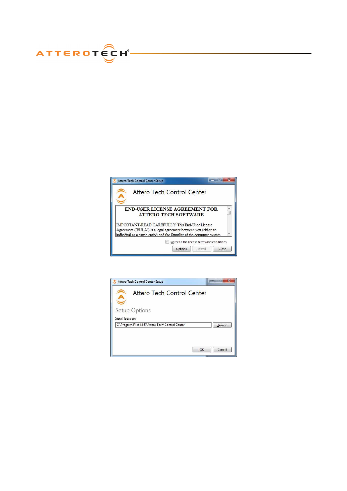
To install the application, double click of the application EXE file to start the application install. At any point during this
installation prior to actually installing the files, the installation may be stopped by clicking on the “Cancel” button.
The application is installed by default into C:\Program Files (x86)\Attero Tech\Control Center. This location may be
changed by clicking on the “Options” button.
A new default location can be typed into the box or click the “Browse” button to browse for the new location. Click OK to
accept any changes. Click cancel to undo any changes
To activate the “Install” button, read the license agreement and if you agree, check the “I accept…” option. Finally, click the
“Install” button to initiate the installation of the files.
Attero Tech LLC 2013 Page 2 614-00002-07
Page 5
Control Center
User Manual
At this point, Windows may pop up a User Access Account window. If it does, click the “Yes” button to allow the installation
to continue.
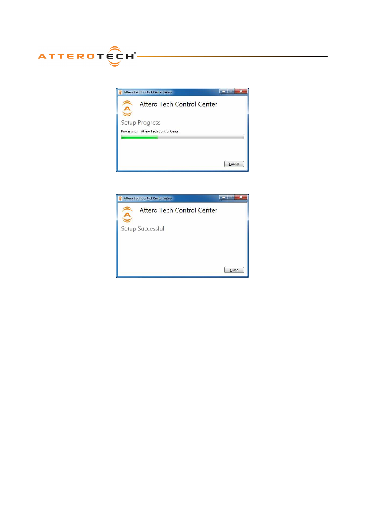
The installer will then begin copying files and display the progress of the installation.
After this process is successfully completed, click “Close”.
The installation will create a program group and various shortcuts including one to run the program. All of the icons are
located under Start Menu -> All Programs ->Attero Tech -> Attero Tech Control Center.
Attero Tech LLC 2013 Page 3 614-00002-07
Page 6

Control Center
User Manual
3 – Running the Application
Control Center runs in one of two modes. There is an online mode (called normal mode) and an offline mode (called demo
mode). For configuring devices on a live CobraNet network, normal mode must be used.
Demo mode can be used to demo the features of the software and Attero Tech devices without the need for an active
CobraNet network and also to provide a method to create device configurations offline for a particular application that can
be downloaded to the live system once it is installed and running. Further information on the two operating modes can be
found in section 3.3.
If Control Center is to be used in normal mode, before the application can be run, it is necessary to configure a network
adapter in the PC to allow it to communicate with CobraNet devices.
3.1 – Setting up the PC Network Adapter
If Control Center is going to be used in Normal mode, it requires that it has access to the CobraNet network through a
correctly configured network card (NIC). To be configured correctly, that NIC requires a valid IP address. This IP address
can either be given to the NIC manually (known as a static IP address), or be given to it automatically over the network
(known as a dynamic IP address). The method of how the NIC in the PC gets its address will depend on the available
facilities of the CobraNet network it is connected to. If the CobraNet network has IP address assignment facilities (such as a
DHCP server), the PC should use that service and be setup to get an address automatically otherwise the NIC should be
assigned a static IP address. For most regularly applications, the PC NIC will likely need to be assigned a static IP address.
*Note: If the network card to be used is set to obtain its IP address dynamically and there is no service on the CobraNet
network to supply an IP address, the PC will fall back to either an alternate address that it has been previously supplied or it
will give itself an automatic private IP address beginning with 169.254.x.x (known as APIPA). In either case, the entire
process can take up to a minute. Control Center will not operate correctly in normal mode if it is started during this time
and will given an error regarding the IP address being invalid (the address is seen as 0.0.0.0).
Once the NIC has a valid IP address, the Control Center application can be started.
Attero Tech LLC 2013 Page 4 614-00002-07
Page 7
Control Center
User Manual
3.2 – The Main Form
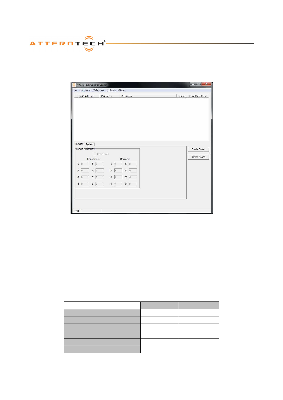
The installation adds a program folder to the programs menu. To start the application, locate the Control Center icon under
Start->All Programs->Attero Tech and click on the Control Center icon. When the application starts, a brief splash screen is
shown before the main window appearsError! Reference source not found..
Figure 1 - Initial Main Window
*Note: When first run, the available software functions will be restricted until either demo mode is selected or a suitable
network card is chosen, CobraNet devices have been located on that network, and one of those devices has been selected.
3.3 – Configuring the Mode of Operation
Control Center runs in one of two modes. There is an offline mode (called demo mode) and there is an online mode (just
called Normal mode).
Demo mode is designed for two specific purposes.
1) To demo the features of the software and Attero Tech devices without the need for an active CobraNet network.
2) To provide a method to create device configurations offline for a particular application that can be downloaded to
Certain functions and features are not available when running in demo mode. Below is a table showing a comparison of
Demo mode and Normal mode. Further information on these features can be found later in the manual.
the live system once it is installed and running.
Demo Mode Normal Mode
Operate with no Network setup
Active network with active devices
Set System parameters
Change Bundle setup
Set Device IP Address
Update device firmware
Yes No
No Yes
No Yes
No Yes
No Yes
No Yes
Attero Tech LLC 2013 Page 5 614-00002-07
Page 8
Control Center
User Manual
Demo Mode Normal Mode
MatchBox Configuration
MatchBox Monitor setup
Device Configuration
Save device Settings
Load device settings
(*) Device Configuration – In normal mode, changes to controls are sent to the device. In demo mode, controls can be
changed but they have no affect on anything other than to set a level which can then be saved.
(**) Load device settings – In demo mode, this can be used to load a pre-saved configuration into memory. In normal mode,
loading a configuration will also send the settings to the device as well.
Control Center will always run using the same mode of operation that was being used last time it was run. In the case the
software is being run for the first time, the application is set to run in normal mode but does not have a network card
selected.
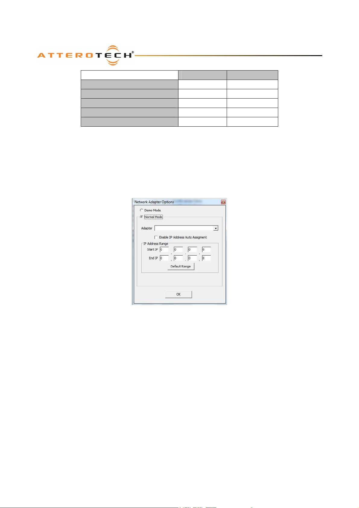
The operating mode and associated settings can be accessed and changed any time while the software is running. This is
done by accessing the Network Adapter configuration. Click Network -> Select Adapter to show the current configuration.
No Yes
No Yes
Yes (*) Yes
Yes Yes
Yes (**) Yes
Figure 2 - Select a Network Adapter Form
3.3.1 – Setting up Demo mode
To run the software in demo mode, select the Demo Mode option. All other settings on this form are not applicable for this
mode and can be ignored. Click the OK button to confirm the demo mode selection.
*Note: This saves the new mode but the application won’t use that new mode until it is closed and restarted.
3.3.2 – Setting up Normal mode
In order to communicate with the CobraNet devices on a live CobraNet network, the application needs to know which
network interface card (NIC) to use. The adapter combo box shows the currently selected adapter. If this is blank, no
adapter is currently in use. Use the adapter drop down box to select the desired NIC from the list of available NIC cards.
*Note: CobraNet specifications require a wired network adapter must be used.
Where there is uncertainty regarding which adapter is which, the correct adapter can be found by selecting each adapter in
turn from the drop down box and then click the default range button. A default IP range based on the selected adapters IP
address will be shown and that should be enough to determine if the correct card is selected. Once the correct NIC has
been selected, the options of how IP addresses are allocated to the CobraNet devices needs to be setup. Details of the
additional options are below. When those options are correctly configured, click OK to save the setup.
*Note: If the mode of operation was not changed, any configuration changes will be immediately applied. However, if mode
of operation is changed, the new settings will only take affect after the application is restarted.
Attero Tech LLC 2013 Page 6 614-00002-07
Page 9

Control Center
User Manual
3.3.2.1 – IP Auto Assignment
*Note: The CobraNet protocol does not require each device is allocated an IP address. Once configured, audio will pass
between devices whether the devices have been allocated an IP address. This is because CobraNet audio transfers are done
just using device MAC addresses. However, in order to configure a CobraNet device, it must be assigned an IP address.
In order to be configured, each CobraNet device must have an IP address. That IP addresses can be set either statically or
dynamically. When configured with a static IP address, the device will always use the same IP address every time it is
powered up or reset. However, with a dynamic address, the CobraNet node is relying on a service on the network to supply
it with its IP address. In a normal network, this service is called a DHCP server. However, most CobraNet networks don’t
have such a facility available. Fortunately, Control Center has an auto IP assignment facility for those CobraNet systems that
need one.
This option should therefore be selected based on the needs of the system. In most systems, Control Center should be set
up to allocate IP addresses to CobraNet devices and so this option should be left selected. However, for systems that
already have a method of IP address allocation, this option should be turned off.
*Note: Setting up Control Center to provide automatic IP assignment has no effect on devices already with an IP address.
The devices will continue to use whatever IP address they were given, irrespective of the method used to obtain it, regardless
of whether Control Center auto assigns IP addresses or not.
3.3.2.2 – IP address Range
This option only takes affect it automatic IP assignment is enabled. It represents the range of IP addresses that Control
Center can give out. The “Default Range” button can be used to select a typical range of compatible addresses for the
selected NIC. However, values can be typed in to manually override the defaults if required.
Attero Tech LLC 2013 Page 7 614-00002-07
Page 10
Control Center
User Manual
3.4 – Main Form Functions
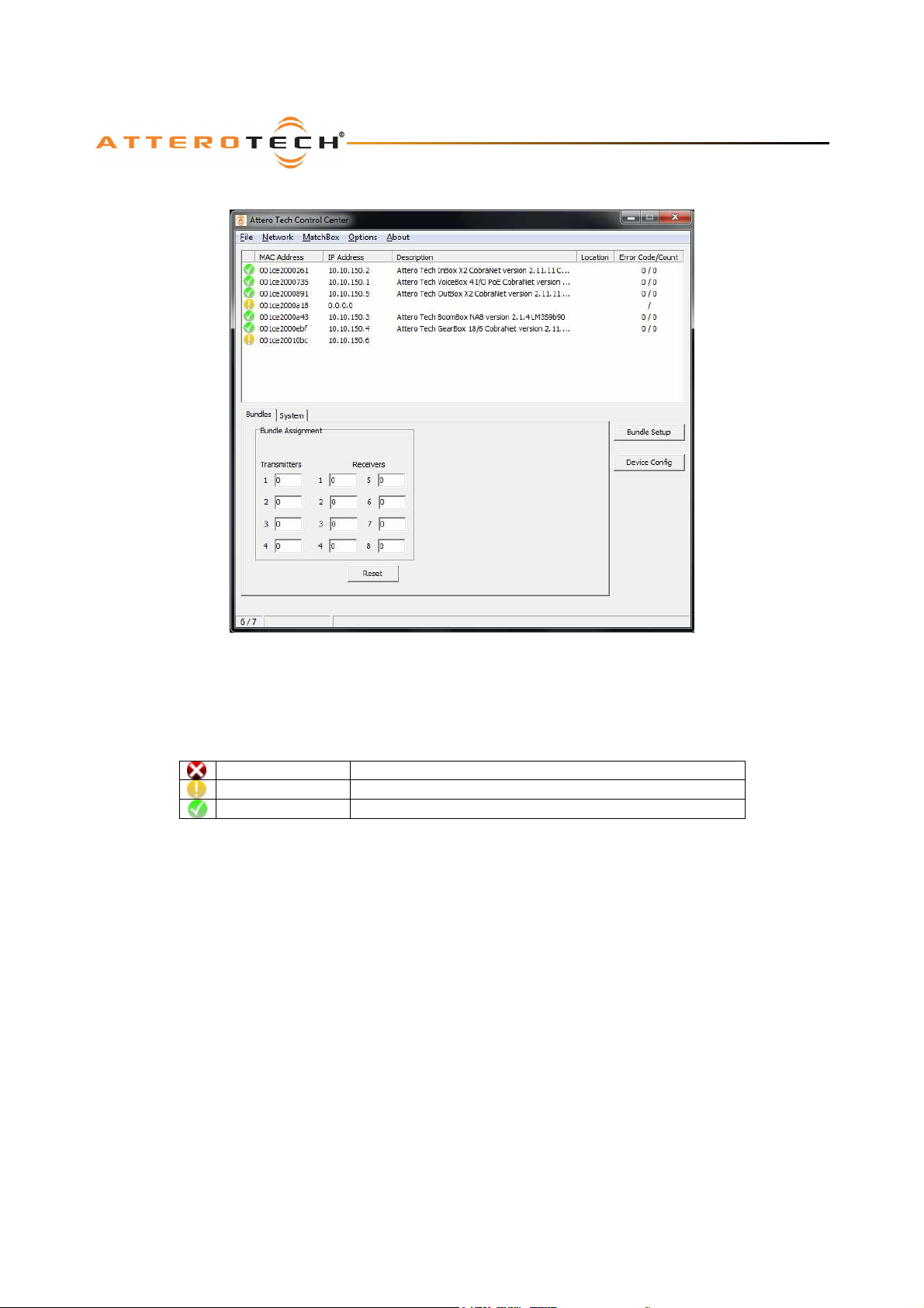
The upper part of the window is the device list. In online mode, this list will be populated as devices are detected on the
active network connection. In demo mode, this list is artificially generated with one of each of the different products Attero
makes.
Each device in the device list has an icon next to it. The icon will be one of three colors:
Offline state Red cross – Device detected previously that is no longer active
Detected state Device detected but no communication
Working state Device detected and communicating
When a device is first detected, it will always show a yellow icon. Once initial contact has been made with it, the icon will
turn green and stay green for as long as the device remains active. If the device is turned off or stops responding, it will
remain in the list but the icon with turn red. As the device list populates, the device list fields will fill. The device list shows
the devices MAC address, current IP address, system description, location, the last error code and the current error count.
*Note: If the error count is zero, any value displayed for error code is meaningless.
At the same time, the field in the bottom left hand corner on the status bar will update. If the software is running in demo
mode, this will indicate only “Demo”. In normal mode, the field shows the number of devices detected (the number before
the slash) and those shown on the list (the number after the slash). The numbers should match. It should be noted there is
a delay between turning on a device, and its consequent detection and appearance on the device list with a yellow icon.
This delay may be several seconds. However, if the device count consistently shows more devices than are shown in the
device list, consult the troubleshooting guide.
Once devices appear in the device list, they may be selected. Only devices in the working state will active the additional
main form features. Only one device may be selected at a time. To select a device, click on it in the device list. This will
highlight the device in the list and populate the values on the lower portion of the form with all the settings from that
particular device. The IP address of the selected device will also appear in the status bar at the bottom of the window.
Once a device is selected, clicking on the Bundle tab will show the bundle number setup for that device. Clicking on the
System tab will show the sysContact and sysLocation parameters as well as serial bridge configuration, if it has any. Only
values on the System tab may be changed. Changes to any of the settings are not automatically sent to the selected device.
Click the Apply button to send the changes to the selected device. Clicking the Reset button will cause the system
Figure 3 - Main Window with Devices
Attero Tech LLC 2013 Page 8 614-00002-07
Page 11
Control Center
User Manual
parameters to be reset back to the settings the selected device has stored. Any on-screen changes can thus be undone by
clicking the Reset button as long as the changes have not been already applied to the device.
*Note: Any changes not applied will be overwritten if the Reset button is clicked. Changes to parameters will also be lost if
a different device is selected before any changes are applied.
3.4.1 – Setting a Devices IP Address
*Note: Not available in demo mode
There may be occasions when a device shows a yellow icon that never goes green because its IP address setup is
incompatible with the IP address setup on the network adapter connected to the CobraNet network in the PC. For example,
its IP address is on a different network to the PC’s IP address or a device is set to get an IP dynamically but Control Center
has the IP auto assignment feature turned off. There may also be times when a device needs to have its IP address
temporarily changed, for example, if a device is using a static IP address that is not in the same network range as the PC
network interface. Control Center has the ability to change the IP address of a device on the fly.
*Note: Changing the IP address of a CobraNet device works irrespective of whether the device has a static IP address, has a
dynamically assigned IP address or even if the device has no IP address at all!
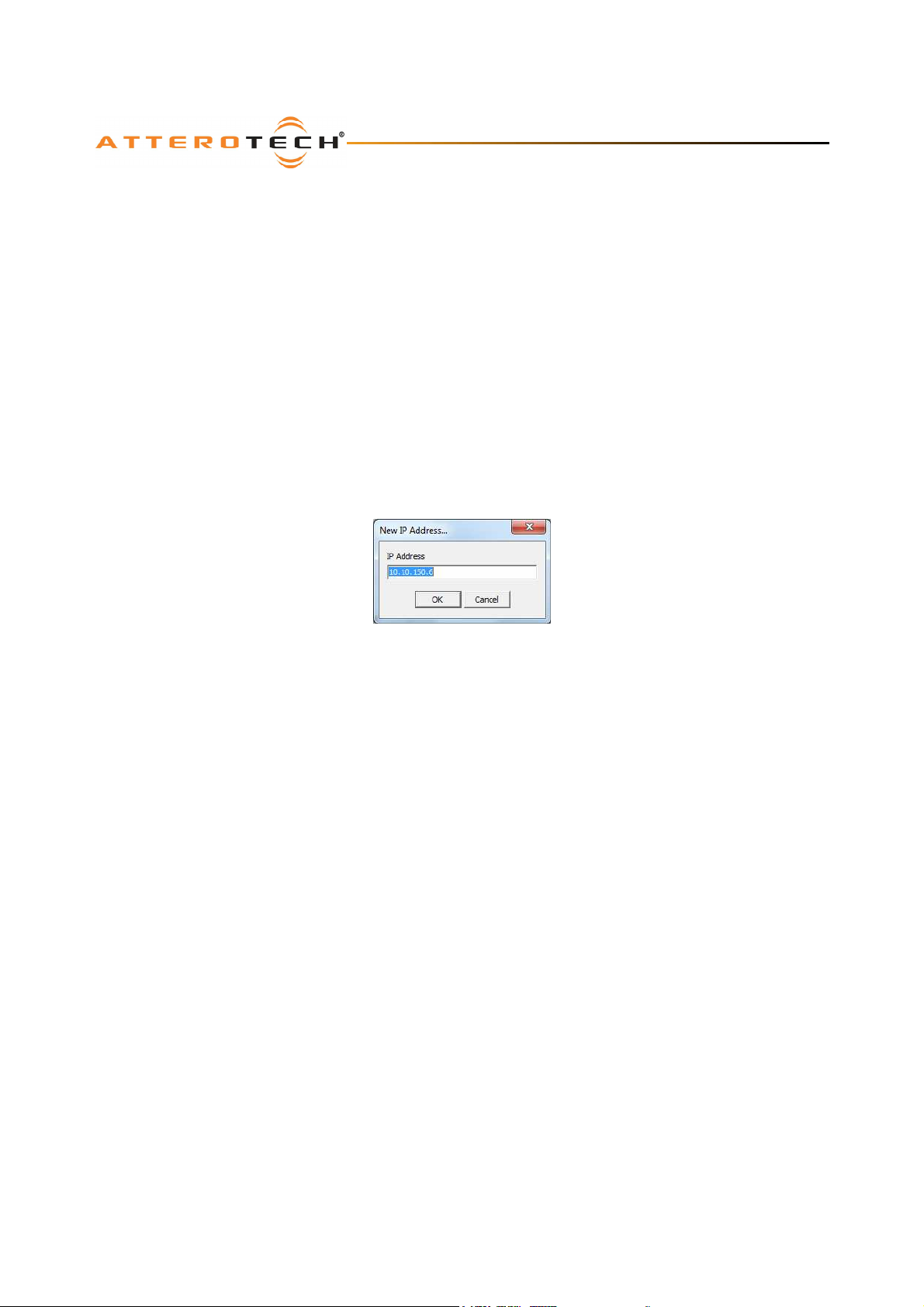
To change the IP address of a device, right clicking on a device in the device list and select the “New IP Address…” option. A
small edit form appears that allows entry of a new IP address.
Figure 4 - New IP Address Form
Enter the new IP Address and click OK. If the IP is valid, it will be applied immediately to the device. Its device list
parameters will clear and Control Center will attempt to re-establish communications using its new IP address. Click the
Cancel button to exit the form without setting a different address.
*Note: Control Center does not check to see if the new IP address will allow Control Center to communicate with the device.
It only checks the IP address has a valid value and is in a valid format.
3.4.2 – Using Static IP Addresses
*Note: Not available in demo mode
Control Center also has the ability to change the way a device gets its IP address by right clicking on a device in the device
and hovering over the IP Address Type menu. The submenu that appears allows selection of a dynamic IP address or a static
one. If dynamic is chosen, Control Center will erase any settings for static IP and static subnet mask. The device will
continue to use its current IP address until such time the unit is reset or the power is cycled. Selecting static allows the user
to enter the static IP address and the static subnet mask for the device. If both entries are validated, the device is
immediately configured with the new parameters and the IP address on the unit is reset to the applied static IP address. The
devices parameters in the device list will clear and Control Center will attempt to re-establish communications using the new
IP address. Click the Cancel button on either the static IP address or static subnet mask forms to exit without changing the
mode or setting any values.
*Note: Control Center does not check to see if the new IP address and subnet mask combination will allow Control Center to
communicate with the device. It only checks they are have a valid value and are in a valid format. An incorrectly set subnet
mask may cause the PC to be unable to contact the device.
3.4.3 – Setting the Static Subnet Mask
*Note: Not available in demo mode
Control Center can view and change the value of the static subnet mask. It can be altered without the need to change the
static IP address. Changing this value will not have any affect on a device unless the device is set to have a static IP address.
Attero Tech LLC 2013 Page 9 614-00002-07
Page 12
Control Center
User Manual
3.4.4 – Configuring System Parameters
*Note: Not available in demo mode,
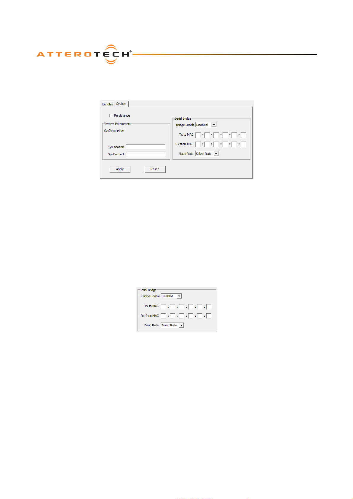
The System tab allows modification of various CobraNet system parameters on the selected device.
Figure 5 - Main Form System Tab
The Persistence check box shows if the device has persistence enabled or not. With this setting checked, the device will
remember any changes to the settings that are applied. With the check box clear, any changes are lost as soon as the
device is powered down or reset and the device will return to the defaults stored in its firmware.
*Note: Changes to the persistence parameter only take affect when applied. If persistence is activated, it may take some
time for the device to process changes to its parameters. Leave the device turned on for a minute after changing the
parameters to ensure persistence has taken affect. Turning the device off before that may result in parameter settings
being lost.
The SysDescription field is read only. The SysContact and SysLocation fields are string fields and have no operational affect
on the device and are used for operator information only. The SysLocation field is the same as appears in the location
column of the device list.
3.4.5 – Configuring the Serial Bridge
Figure 6 - Serial Bridge Parameters
*Note: Not available in demo mode,
The Serial Bridge parameters are shown on the System tab as well. The MAC addresses for receiving and transmitting are
entered as six separate 2-digit hexadecimal numbers. This can be the address of a specific device or a multicast address.
The Baud Rate can also be altered. Possible rates are 2400, 9600, 19200, 38400, 57600 and 115200.
*Note: The Tx to MAC, Rx from MAC, and Baud Rate parameters can only be altered while the serial bridge is disabled. To
alter these settings if the Serial Bridge is enabled, the Bridge Enable parameter must be set to “Disabled” and then the Apply
button must be clicked. The parameters will then become active and can be changed.
Click the Apply button to apply any changes to the selected device. The Tx to MAC, RX from MAC, and Baud Rate
parameters will all be disabled if changes applied include enabling the Serial Bridge.
*Note: For more information on the Serial Bridge feature of CobraNet including Multicast MAC address values, see the
relevant section in the CobraNet Programmers Guide.
Attero Tech LLC 2013 Page 10 614-00002-07
Page 13
Control Center
User Manual
3.4.6 – Device Firmware Update
*Note: Not available in demo mode,
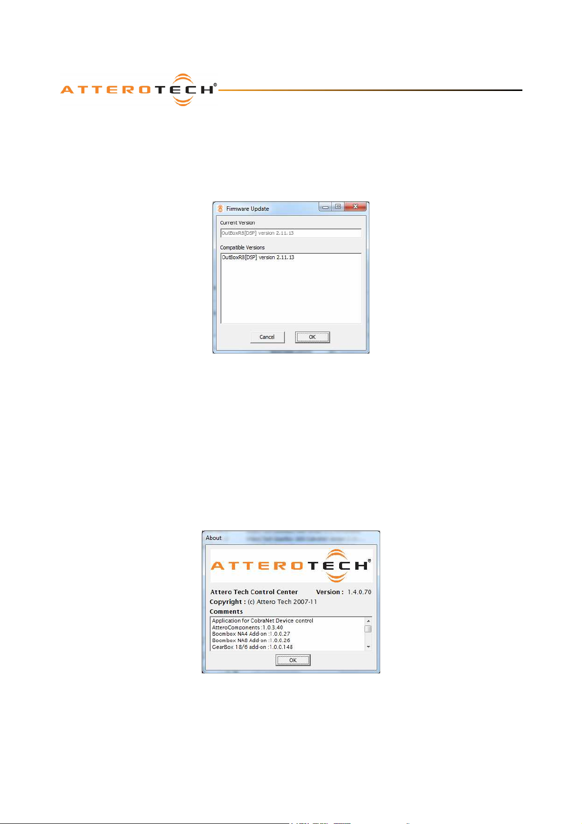
The firmware update option allows Control Center to apply new CobraNet firmware to an Attero Tech device. The firmware
update feature is accessed by right clicking on a device and selecting the Firmware Update option. The feature is limited to
Attero Tech products only. New firmware files for Attero Tech devices are only available from Attero Tech. These firmware
files should be placed in a folder named “Firmware” in the Control Center installation directory otherwise the update feature
will not find them.
Figure 7 - Firmware Update form
A form like that in Figure 7will appear. The current version should show the versions the application thinks is in the device.
The list below it contains all compatible code of the current version.
*Note: This feature only works if the application can ascertain what the current firmware for a device is. If Control Center
is unable to detect the current firmware version, contact Attero Tech’s technical support
To apply an update, select the required firmware for the device from the list and click OK. Control Center will then apply the
firmware to the device which can take a couple anything from a few seconds to a couple of minutes.
*Note: Once the firmware update is complete, the device will continue to operate using the original firmware it contained.
The device must be power cycled to complete the update process and use the newly loaded version.
3.4.7 – About
Information about the application can be found by clicking on the Help-> About menu option
Figure 8 - About form
The form shows the version of Control Center being run and also all the add-ons that are currently installed along with their
version.
Attero Tech LLC 2013 Page 11 614-00002-07
Page 14
Control Center
User Manual
4 – Bundles
Bundles are the method by which audio is routed around a CobraNet network. Some notes on bundles are included in the
relevant sections but for further information on audio routing and bundles in CobraNet, see the Introduction to CobraNet in
Error! Reference source not found. and the reference documents listed in APPENDIX B.
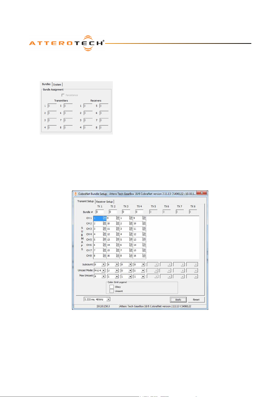
The Control Center main form shows an overview of the bundle
setup by displaying the bundle numbers a device is transmitting and
receiving. Up to eight transmitters and eight receivers can be
displayed. These values are updated each time a device is selected.
These are read only fields and only the bundle transmitters and
receivers that Control Center determines are available for the
selected device will be shown.
The current state of the persistence parameter is also shown. This
value only shows what the device is currently set to. If persistence is
Figure 9 - Bundle number settings on Main
Form
4.1 – Bundle Setup
*Note: Not available in demo mode,
Editing the bundle settings requires using the Bundle Setup form. This not only allows viewing and setting of bundle
numbers, but also the configuration of other audio routing parameters. To open the Bundle Setup form, select the device in
the device list and click the Bundle Setup button.
not set, any bundle information will be lost if the unit is powered
down or reset for any reason. In some applications, this is desirable.
If bundle values are not going to change, this feature should be
turned on.
The form has two tabs. The Transmit Setup tab contains the devices bundle transmitters while the Receiver Setup tab
contains the devices bundle receivers. Depending on the tab selected, up to eight bundle transmitter or eight bundle
receivers can be displayed. However, the software limits how many bundle transmitters and receivers that are available for
editing by interrogating the device to determine how many bundle transmitters and receivers it actually has.
*Note: Alterations to any settings on this form have to be applied for them to take affect on the unit. Like the main form,
unapplied changes can be reset back to the device’s current values by using the Reset button.
Attero Tech LLC 2013 Page 12 614-00002-07
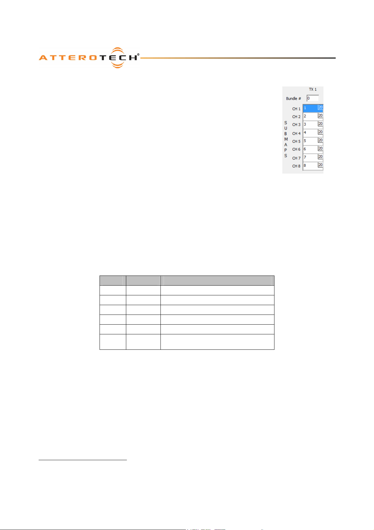
Figure 10 - Bundle Setup form showing Bundle Transmitters
Page 15
Control Center
User Manual
4.2 – Transmit Bundles
The bundle transmitter setup tab (see Figure 10) contains all the parameters to set up a
devices bundle transmitters.
Edit boxes containing the bundle number used for each bundle transmitter are shown at the
top. Below these, the submap grid shows which audio channels are allocated to a bundle.
The number in the top right hand corner of each cell is the sample bit depth. Below the
submap grid, drop down boxes for setting the Subcount, Unicast Mode, and Max Unicast
parameters are given.
Clicking on a bundle edit box or on a cell in the submap grid will select the item so it can be
edited. The bundle number accepts values from 0 to 65535 though private bundles (65280 to
65535) are not supported. For the submap, valid values are from 0 to 32 with a zero meaning
no audio. See section 4.2.1 for more details about bundle numbers and submap settings.
To alter the bit-depth in the submap grid, right click anywhere within the desired cell. This
will display a pop up menu showing the possible options for the bit-depth. The current
selection will be ticked. Click on an alternate value or click anywhere except the menu to keep
the current one.
*Note: Changing the bit depth has consequences. Adding more bits/sample increases the amount data sent over the
network and reduces the number of channels a bundle can hold. Further Information on this can be found on the CobraNet
Programmers Guide.
Other settings available for each transmitter are:
o Subcount – This drop down list configures the bundle to only use the specified number of audio channels. The
cells in the grid above are colored based on this setting. Channels that are being used have a white background
and channels which are not being used have a grey background (see Figure 10). However, the colors shown relate
to the value in the device not the value on the form. If this parameter is changed on the form, it must be applied
for the colors in the grid to update.
o Unicast Mode – This drop down menu specifies the transmission mode. It works in conjunction with the Max
Unicast value. The table below describes the operation of each mode.
Mode Value Description
M 0 Multicast always.
M-U 1 1 Unicast a single channel. Multicast if more.
M-U 2 2 Unicast up to 2 channels. Multicast if more.
M-U 3 3 Unicast up to 3 channels. Multicast if more.
M-U 4 4 Unicast up to 4 channels. Multicast if more.
U 0x7FFFFF
o Max Unicast – This drop down menu specifies the maximum number of unicast destinations supported
simultaneously by the transmitter1. It can be set between 1 and 4. Its actual affect is dependant on the setting on
Unicast Mode. If Max Unicast is greater than or equal to Unicast Mode, the bundle will switch to Multicasting
before the limitation on unicasts set by this parameter is reached. In this case, Max Unicast has no effect. If Max
Unicast is less than Unicast Mode and the number of receivers exceeds Max Unicast, the receivers will not receive
audio. However, if the number of receivers exceeds the Unicast Mode value, the bundle switches to Multicasting
and this parameter then has no effect. This parameter is ignored if Unicast Mode is set to Multicast only.
Unicast only. The device can still send to
multiple channels using multi-unicast.
Figure 11 - Receiver
Submap
1
A transmitter can service up to four unicast receivers. The number of unicast destinations transmitted to will never exceed
this internal capacity limitation.
Attero Tech LLC 2013 Page 13 614-00002-07
Page 16

Control Center
User Manual
4.2.1 – Notes on Transmit Bundles
Setting the correct bundle number for the mode is vitally important. The bundle number should be set based on the
transmission type. If the bundle is going to be unicast or multi-unicast, the bundle number should be between 256 and
65279. For multicast bundles, the bundle number should be between 1 and 255. Using a multicast bundle with a bundle
number higher than 255, or using a unicast bundle with a bundle number less than 256, may result in the audio not being
transmitted across the network.
Transmitter submap assignments in bundles should always be populated in the bundle starting with submap Ch1 and
working down. The values in transmitter submap represent the audio from a particular CobraNet output. A value zero
represents no audio. A value of 1 represents the audio from CobraNet output 1. A value of 2 represents the audio from
CobraNet output 2 and so on. Each output audio stream can be allocated as many times as required in as many bundles as
required. This means the audio can be duplicated multiple times in the same bundle (normally not done as a single copy of
the audio is normally enough but may be required given a particular application). It also means the same audio can also be
used in more than one bundle too.
Whilst the values 1 through 32 are valid numbers, the actual usable channels on a device will depend on the device being
set up. Some devices have up to 32 CobraNet output channels while others are only capable of 2 (refer to the device’s user
manual for information on what CobraNet output channels are available for that device). Care should be taken when
allocating channels to submaps to ensure only usable audio channels are included in bundles.
The subcount should also be set based on the number of channels actually needed. Setting up a bundle with a subcount of
8 and only placing four active channels in it with the remaining channels being either being set to zero or a non-used audio
channel will still result in eight channels worth of data being sent across the network. The unused channels with simply
contain zeros or random data (depending on exactly how the bundle is set up and what CobraNet output audio the device
has available). This wastes network bandwidth and under certain conditions, may cause audio issues due to excessive
network bandwidth usage.
Another point to note is that the default settings of 5.33ms latency and 20-bit audio allows the full 8 channels of audio to
be used. Changing the bit depth and/or the latency affects the number of channels a bundle may hold. A bundle can never
hold more than eight audio channels but adding more bits/sample or decreasing the latency can restrict the maximum
number of channels in a bundle to less than 8. More details on the restrictions and how these settings affect the channels
count in a bundle can be found if the reference documents noted in APPENDIX B.
There can also be bandwidth-related consequences and added congestion when adding Multicast traffic to the network. See
Bundle Assignment White Paper at http://www.cobranet.info/support/design/bundle_assignments.
Attero Tech LLC 2013 Page 14 614-00002-07
Page 17
Control Center
User Manual
4.3 – Receiver Setup
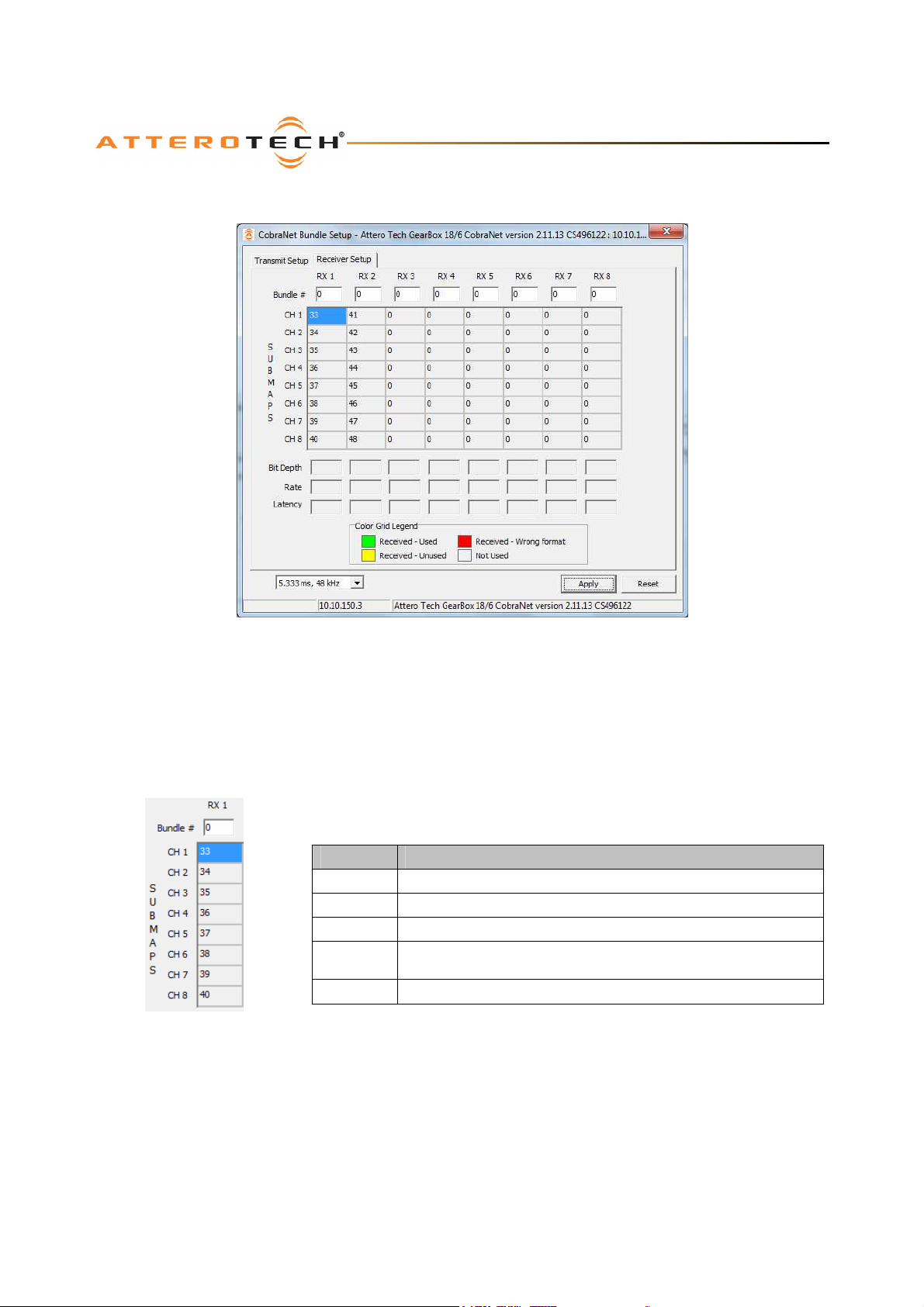
The Receiver Setup tab is show in (Figure 13). Like the transmitter tab, bundle edit boxes for each bundle receiver are given
above the submap grid. The values in the receiver submap grid represent which of the incoming audio streams from a
bundle are assigned to the devices CobraNet inputs.
Clicking on a bundle edit box or on a cell in the submap grid will select the item so it can be edited. The bundle edit boxes
accept values from 0 to 65535 though private bundles (65280 to 65535) are not supported. Valid values for the submaps
are 33 to 64 or use 0 to ignore the audio in that slot and essentially throw that audio away.
The receiver status is constantly monitored in the background. The background color of each cell is updated based on its
Figure 13 - Receiver Submap
In addition to the grid coloration, any active bundle will also populate the fields below the submap grid showing what sort of
audio is being recevied.
value and the receiving state of the bundle. The form contains a legend for quick
reference with details of the grid colors. A table of the colurs and what they mean is
included below.
*Note: The grid coloring is only done against the values the device is currently using
therefore any changes to the settings that have not been applied won’t be taken into
account.
Figure 12 -Bundle receiver setup
Cell Color Description
Blue Cell selected
Green Active audio is being received and used
Yellow Active audio not being used
Red
Grey Audio not being received
Received audio is in an unusable format (Latency and/or sample rate
do not match the devices latency and sample rate)
Attero Tech LLC 2013 Page 15 614-00002-07
Page 18

Control Center
User Manual
4.3.1 – Notes on Receive Bundles
The submaps in the receiver submap grid work a little differently to those in the transmit submap grid. Each CobraNet
input is assigned a number. The value 33 represents input 1, 34 represents input 2 and so on. However, unlike the
transmit grid, each CobraNet input can only receive a single stream. This means that the only a single instance of each
input value should be used across the entire submap grid (the only exception being the value 0 which can be used as many
times as necessary). Using the same CobraNet input value on two active streams *WILL NOT* result in the streams being
mixed. CobraNet is only a transport mechanism and cannot mix signals en-route.
If two incoming audio streams in a device do have the same CobraNet input assigned to them, whether they are from the
same bundle or different bundles, one stream will be used, the other will not. This may be a desirable use case in certain
applications but further reading on which stream the device uses is advised.
Whilst the values 33 through 64 are valid numbers, the actual usable channels on a device will depend on the device being
set up. Some devices have up to 32 CobraNet input channels while others are only capable of 2 (refer to the device’s
manual for information on what CobraNet input channels are available for that device). Care should be taken when
allocating input channels to submaps to ensure only usable input channels are used.
4.4 – Mode Rate Control
The Mode Rate Control drop down is below the bundle transmitter setup. The value it contains determines both the sample
rate and latency of the device but from a single value. Sample rates of 48 kHz or 96 kHz can be selected with latencies of
1.333ms, 2.666ms, or 5.333ms.
****** Warning *****
Great caution should be taken before altering this parameter for a device. This is especially true as the value
controls two separate variables: sample rate and latency. If a device uses on-board DSP, changing the latency is OK
but changing the sample rate may be detrimental to device operation and may stop it from functioning completely.
*********************
For Attero Tech products, any latency value can be used provided the sample rate value remains the same. Products such as
VoiceBox, DialogBox, InBox, and OutBox contain DSP processing that is linked to a sample rate of 48 kHz. Changing the
sample rate (regardless of what latency used) for these devices will be detrimental to the device in question and may cause
the device to cease functioning.
For non-Attero Tech devices, consult the manual of the device you wish to alter the sample rate of to verify that the sample
rate is supported and it is safe to change. If in doubt, DO NOT change this value. Attero Tech takes no responsibility for
the incorrect operation of a non-Attero Tech device if this software is used to alter the device’s ModeRateControl parameter.
Attero Tech LLC 2013 Page 16 614-00002-07
Page 19

Control Center
User Manual
5 – MatchBox Controls
MatchBox control is also part of Control Center. Two MatchBox features are available. They are the MatchBox Device
Configuration tool and the MatchBox Monitor tool. Both tools are accessed through the MatchBox Menu and are only useful
if a MatchBox is plugged into a USB port on the machine running Control Center. Detailed instructions on their use are
available in the MatchBox User Manual but notes are included here for completeness.
5.1 – MatchBox Device Configuration
The MatchBox Device Configuration tool allows the user to alter the configuration of devices/channels in a MatchBox,
selecting whether they are inputs to the PC or outputs from the PC.
5.2 – MatchBox Monitor
The MatchBox Monitor is a tool that allows live audio from a microphone or line input to be placed onto the CobraNet
network via the MatchBox. It also can route CobraNet audio via the MatchBox to a local sound card for local monitoring.
Attero Tech LLC 2013 Page 17 614-00002-07
Page 20

Control Center
User Manual
6 – Device Setup for Attero Tech Devices
Certain CobraNet devices from Attero Tech, such as the VoiceBox 4 I/OP, DialogBox, and the InBox and OutBox products,
utilize on-board DSP processing capabilities and contain additional configurable parameters not covered so far in this
manual. Other devices such as the BoomBox NA4 and NA8 and the SquawkBox, don’t have any DSP but have specific
controls unique to them.
The Control Center application contains interfaces that allow these additional parameters to be viewed and configured.
Each type of device has its own interface. To gain access to these parameters and settings, either
a) Right click on the device in the device list and click the Device Setup option from the pop-up menu
b) Left click on the device in the device list and click the Device Setup button.
Details of the settings for each individual device is included in the devices own user manual.
Attero Tech LLC 2013 Page 18 614-00002-07
Page 21

Control Center
User Manual
7 – Troubleshooting
Ensure your software is the latest version. The latest released version can be obtained from the Control Center Download
section of the Attero Tech website (www.atterotech.com).
7.1 – Network Setup
Before beginning troubleshooting devices and software, it is worth first checking that the CobraNet Network is correctly
constructed and connected.
o Use a crossover cable to directly connect a device to a PC
o Where multiple CobraNet devices are used, the CobraNet network must be built using Ethernet Switches. Ethernet
Hubs must not be used
o The use of 10 Mbit/s connections should be avoided
o The use of wireless connections must be avoided
o CobraNet is not routable so the use of routers should be avoided (using CobraNet through the embedded switch of
a residential type of router is OK as long as audio and control data is not required on the WAN side of the router).
o CobraNet devices all run at 100 Mbits/s so connections from the CobraNet device to the network must be capable
of running at 100 Mbits/s
o Connections between individual infrastructure devices (switch to switch, etc.) can run at 100 Mbits/s or above
Also be wary of having multiple instances of Control Center running on different machines but connected to the same
CobraNet network. If both try and access the same device, particularly using the DSP interface with metering enabled, both
machines will send multiple refreshes for the metering and will bog the device down under a barrage of SNMP messages.
7.2 – Possible Issues
No devices are detected (status bar device count shows 0)
o Check the OS running is not 64-bit
o If running under Vista, check the version. Only version 1.1.0.30 or later are Vista-compatible
o If running under Windows 7, check the version. Only version 1.2.0.58 or later are Windows 7 compatible
o If running Control Center V1.1.0.30 or later, check that other CobraNet software (such as CobraNet Discovery
V4.0.0 or later) is not running at the same time
o If running Control Center V1.1.0.30 or later and the PC running Control Center hibernates
was active, all devices will seem to disappear when the PC is reactivated. The only known way to get the devices to
re-appear is to close the software and run it again.
o Check the CobraNet devices are powered up and correctly connected
o Check to ensure the PC is correctly connected to the CobraNet network
o Check the cables are corrected and properly terminated
o If a managed switch is used, check the settings on the switch to ensure it is not interfering with the packet flow.
o Ensure the PC has a correctly assigned IP address
o Ensure the correct network card has been selected that is connected to the CobraNet network
o Ensure whatever firewall the PC may have allows access for Control Center messages
o Some Internet security applications can interfere with Control Center’s operation
No network cards are available to be selected
o Check the PC has network cards installed
o Check the operating system and if running under Vista, ensure V1.1.0.30 or later is being used.
o Check the operating system and if running under Windows 7, ensure V1.2.0.58 or later is being used.
Devices are detected (yellow icon) but do not show as fully working (green icon).
o If static IP addresses have been assigned to the CobraNet devices, ensure the PC network card IP address and
subnet mask are set correctly so the PC can communicate with them
o Check for other PCs running Control Center or other CobraNet software (such as CobraNet Discovery). They may
have allocated devices a temporary IP address that is not usable with the IP/subnet mask combination of this PC
running Control Center. Close any other such software and then cycle power on the device to reset any temporary
IP address it may have been given previously
o Close the application, disconnect then reconnect the PC Ethernet cable then restart the application
o Check the cables are corrected and properly terminated
o If a managed switch is used, check the settings on the switch to ensure it is not interfering with the packet flow.
2
while Control Center
2
Hibernation mode is where the PC is essentially turned off but keeps its memory active. Many PCs indicate this mode
using the power LED by flashing it. The PC is not in hibernation if the PC runs a screen saver or it turns off the monitor to
save energy.
Attero Tech LLC 2013 Page 19 614-00002-07
Page 22

Control Center
User Manual
“SNMP update Failed” message appears in the status bar
o Check the device is still connected to the network. If it is, change the settings again and retry
o Ensure another PC is not attempting to access the same device with metering enabled
Devices do not remember any updated values
o Ensure that after making changes, the Apply button is clicked
o If the device forgets the settings during a power off, ensure that the Persistence setting is on
o If the settings are DSP-related from one of the Device Setup forms, ensure the Save as Default button is pressed to
save the default values to flash
Attero Tech LLC 2013 Page 20 614-00002-07
Page 23
Control Center
User Manual
APPENDIX A – Introduction to CobraNet
CobraNet is an audio networking technology for delivery and distribution of real-time, high quality, uncompressed digital
audio using a standard Ethernet network. It is implemented using a combination of hardware, firmware, and the CobraNet
protocol.
Unlike other audio networking or distribution technologies, CobraNet is a true network and exists on standard Ethernet
networks using standard Ethernet hardware. Since it is a true network, audio routing is highly flexible between network
nodes and can be used in a variety of audio distribution applications.
In addition to the high degree of routing flexibility that CobraNet provides, the technology also incorporates the ability to
monitor and control CobraNet devices remotely. This is a key feature that is highly important in fixed installation
applications where the audio distribution equipment may not be readily accessible. All CobraNet devices on the network can
be controlled and monitored from a central location by sending control commands and monitoring device specific
parameters.
CobraNet provides this capability by implementing Simple Network Management Protocol (SNMP). SNMP is a standard
protocol typically used for monitoring network devices such as Ethernet switches. In the case of CobraNet, it allows users to
communicate with any CobraNet device using standard SNMP tools or a customized user interface designed specifically for
CobraNet, such as Attero Tech’s Control Center application.
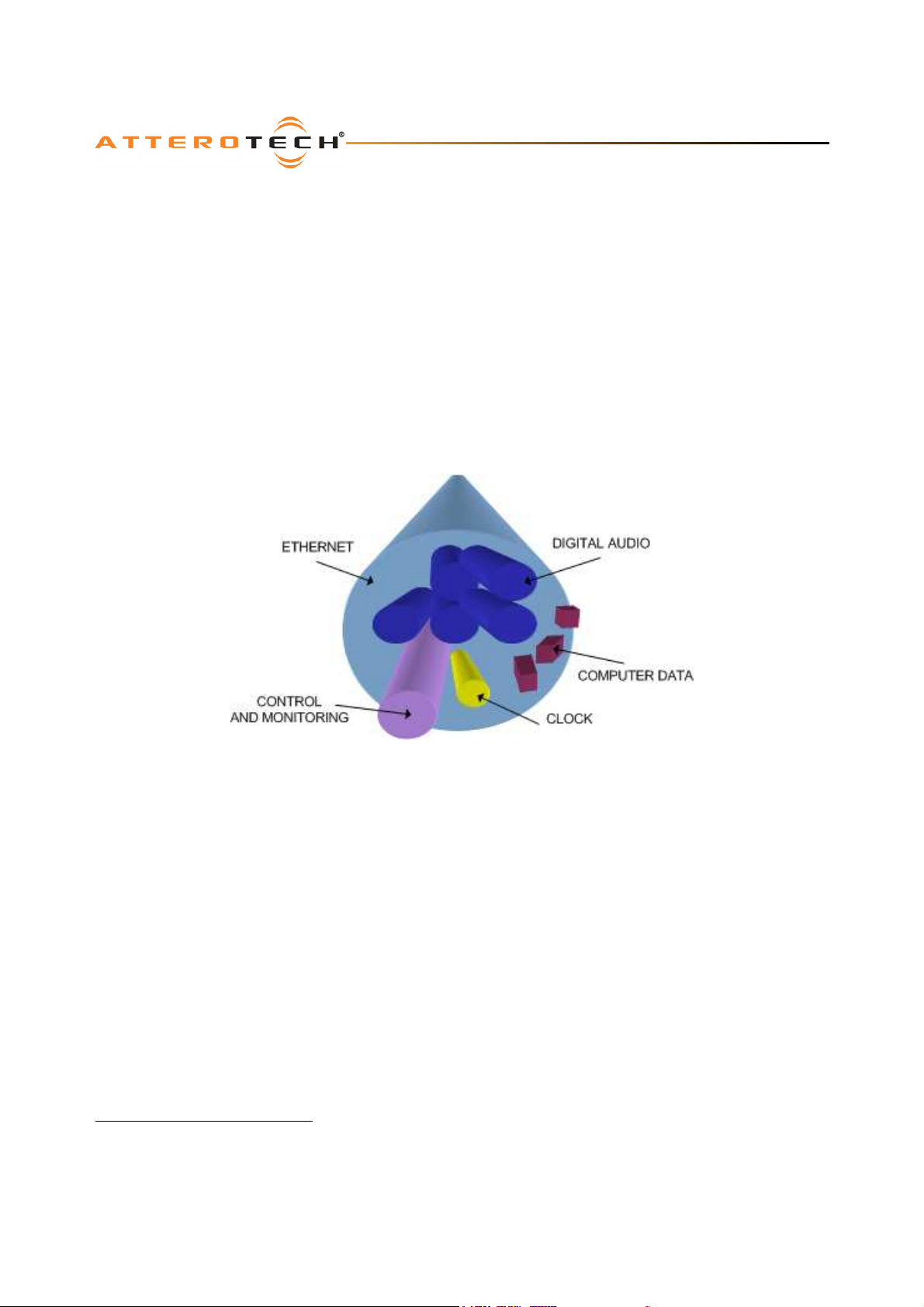
The figure above represents the types of data that coexist on a CobraNet network.
Before a CobraNet system can be configured, it is important to first understand how CobraNet distributes audio between
devices.
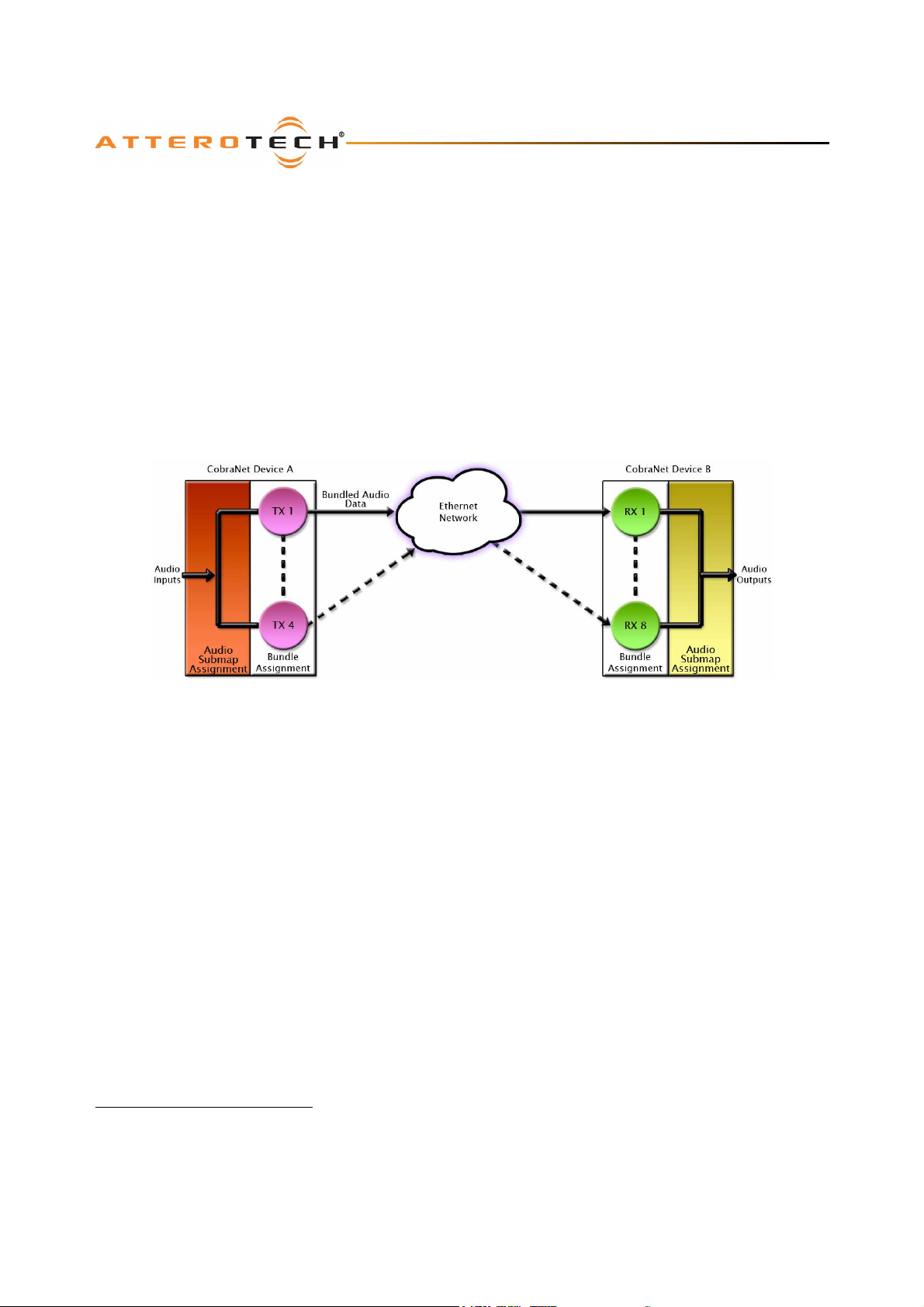
Audio is sent in "bundles" on a CobraNet system. Each bundle is capable of holding up to 8 logical audio channels. Every
CobraNet device has a number of bundle transmitters and bundle receivers. These transmitters and receivers are the
mechanism used to send and receive bundles between devices.
For a transmitted bundle, audio may be sourced either directly from the local audio inputs of the device or from internal
audio via the on-board DSP3, but not both simultaneously. Internal audio from the onboard DSP could have originally been
sourced from the local device inputs, sent from another CobraNet device or even generated by the DSP itself. Combinations
of the local or internal audio may exist within a bundle in any order. Additionally, a single audio source in a device may be
used multiple times in a single transmitter bundle or across multiple transmitter bundles.
For a received bundle, the received network audio may be routed directly to the device’s local outputs, the internal DSP3 or
simply ignored.
Once the contents of a bundle have been decided, the next step is to pass the bundle to another CobraNet device. To do
this, every CobraNet device has up to 4 bundle transmitters. Each bundle transmitter has a transmit mode that must first be
selected. This affects how many devices may receive that particular bundle at a time.
3
Not available on all devices – CS496xxx devices only
Attero Tech LLC 2013 Page A-1 614-00002-07
Page 24
Control Center
User Manual
The modes are as follows:
o Unicast – Used for one-to-one connections. In this mode, only one receiver at a time can receive this bundle. Once
a link is established from this transmitted bundle to a receiver, any future requests for that bundle from other
potential receivers will fail.
o Multicast – Used for one-to-many connections. This mode broadcasts its contents over the entire network. There
is no restriction on the number of receivers. However, the downside is that CobraNet packets are distributed to all
nodes on the network, whether they need them or not thus creating possible network bandwidth issues.
o Multi-unicasts – Another one-to-many mode. Whilst this is the most efficient method for getting a bundle to
multiple receivers in terms of network bandwidth, it requires more processing power on the CobraNet device so in
this mode there is a maximum limit of four receiver connections (this can be reduced if required). If more
connections are required than the limit, the node can be configured to automatically switches to multicast.
*Note: When a bundle must be transmitted to multiple receivers, multi-unicast transmissions should be used where possible.
Once the mode is selected, to enable a device to transmit the bundle, simply allocate the particular transmitter bundle a
non-zero number. Since this number identifies all the network packets sent out by that transmitter, each transmit bundle
number must be unique on a network4.
Now that the transmitter is set up, it is time to set up the receivers. In order to receive bundles, each CobraNet device has
up to eight bundle receivers. To enable a device to receive a bundle, simply allocate one of that device’s bundle receivers
the same bundle number as a transmitted bundle. By doing so, a virtual link is created and audio should now be passed
from one device to the other. It should be noted that no knowledge of a device’s network topology or connection is thus
required in order to configure audio connections. The only restriction to this is that a device cannot be set up to receive a
bundle it is also transmitting.
The above case creates a simple, one-to-one, unidirectional link. If more devices are required to receive that bundle,
allocate the same transmitted bundle number to a bundle receiver on the other CobraNet devices.
It is also important to note that CobraNet supports simultaneous bidirectional audio distribution in each device. Not only
could audio be sent from Device A to Device B but at the same time, should it be needed, audio could also be sent from
Device B to Device A. The exact bundle and routing configuration will be determined by the needs of each individual
installation. An installation may have multiple units transmitting multiple bundles. The only restriction is the bandwidth
available on the network to transfer the audio.
CobraNet does more than just transfer audio data. It can be used to pass serial information as well. A feature called serial
bridging has been incorporated that allows the passage of serial data between nodes. Each node can pass serial data to a
specific node or multicast the data to multiple nodes. A node can also receive data from either a single source or multiple
sources. Baud rates, data bits, stop bits, parity, and so on are all configurable. There is also support for multi-drop serial
buses as well.
Finally, CobraNet has the capability to alter all of the above options in real time making the whole system completely
dynamic. By use of control software, all of the bundle assignment parameters can be configured with no need to change
cables, switch out connectors, or pull new wiring. Most importantly, this control capability can be implemented from a
single location!
4
Bundle numbers range from 1 through 65535. A value of 0 represents an inactive bundle. Numbers 1-255 are reserved
for multicast mode transmissions only.
Attero Tech LLC 2013 Page A-2 614-00002-07
Page 25
Control Center
User Manual
APPENDIX B – Reference Documents
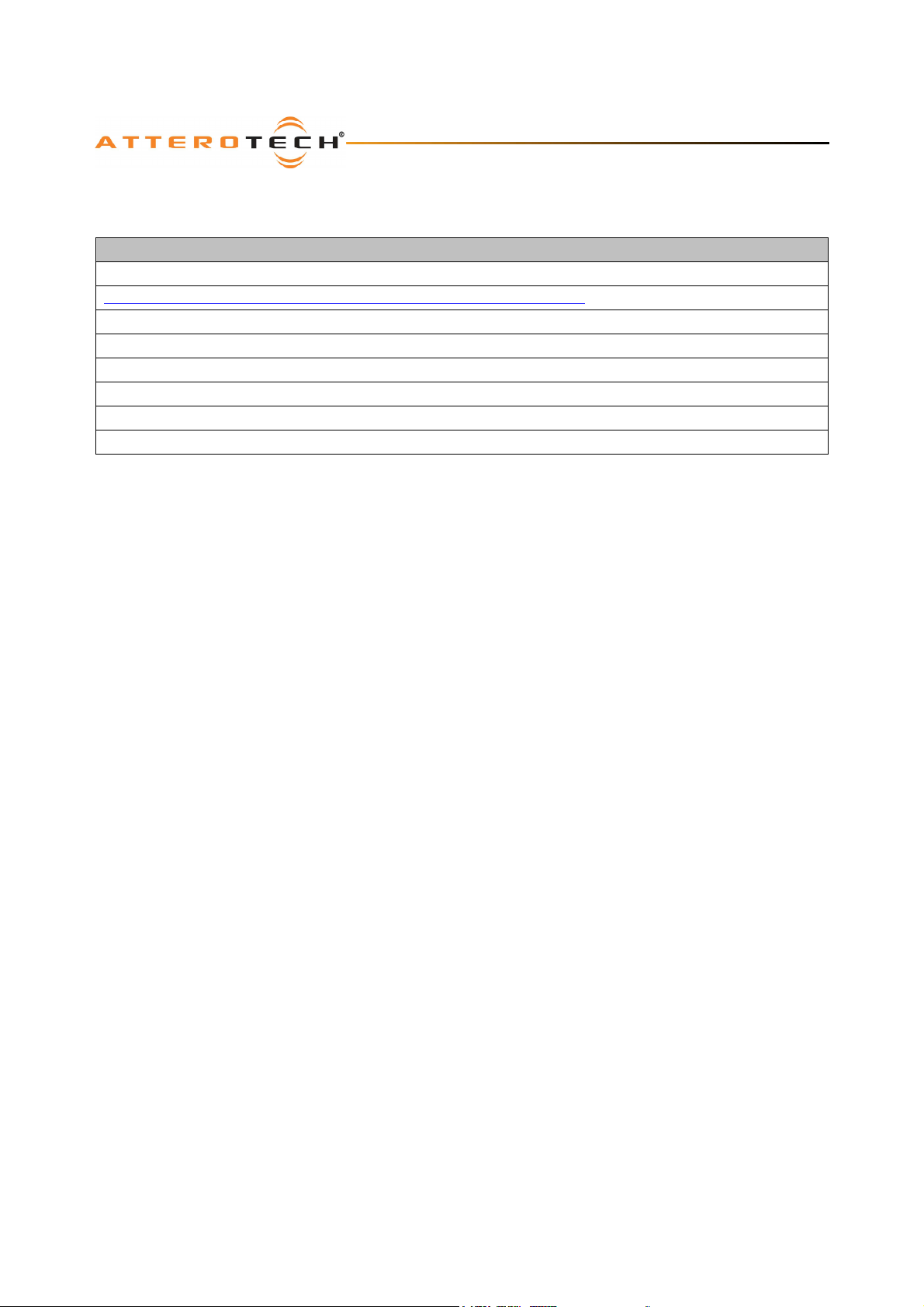
The following table lists the relevant reference documents.
Document Title
CobraNet Programmer’s Reference (Cirrus Logic)
http://www.cobranet.info/en/support/cobranet/design/bundle_assignments.html
Attero Tech MatchBox User Manual
Attero Tech VoiceBox User Manual
Attero Tech InBox/OutBox User Manual
Attero Tech BoomBox NA4 User Manual
Attero Tech SquawkBox User Manual
Attero Tech DialogBox User Manual
Attero Tech LLC 2013 Page B-1 614-00002-07
 Loading...