

Page 1
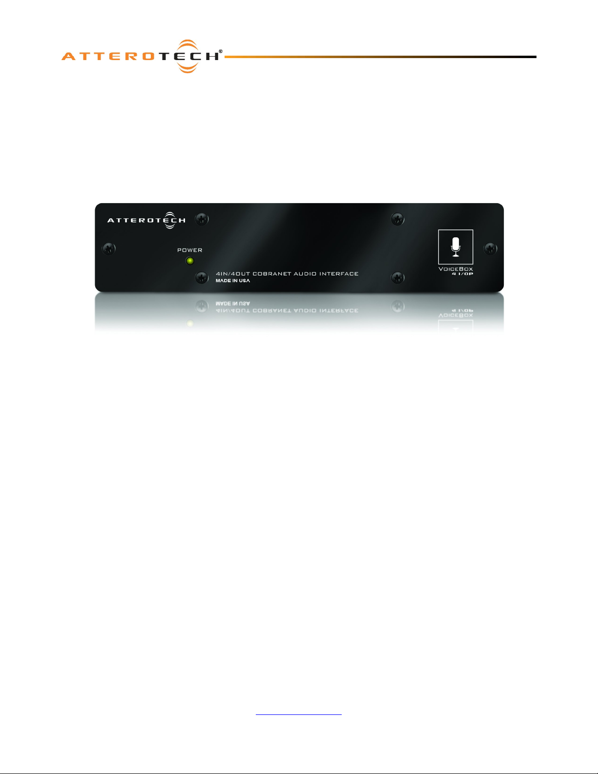
VoiceBox 4 I/OP
User Manual
Date 10/22/2010
Revision 02
Attero Tech, LLC
1315 Directors Row, Suite 107, Ft Wayne, IN 46808
Phone 260-496-9668 • Fax 260-496-9879
www.atterotech.com
614-00008-02
Page 2

VoiceBox 4 I/OP
User Manual
IMPORTANT SAFETY INSTRUCTIONS
The symbols below are internationally accepted symbols that warn of potential hazards with electrical products.
This symbol, wherever it appears, alerts you to the presence of uninsulated dangerous voltage inside the enclosure --
voltage that may be sufficient to constitute a risk of shock.
This symbol, wherever it appears, alerts you to important operating and maintenance instructions in the accompanying
literature. Please read the manual.
1. Read these instructions.
2. Keep these instructions.
3. Heed all warnings.
4. Follow all instructions.
5. Do not use this apparatus near water.
6. Clean only with a dry cloth.
7. Do not block any ventilation openings. Install in accordance with the manufacturer's instructions.
8. Do not install near any heat sources such as radiators, heat registers, stoves, or other apparatus (including
amplifiers) that produce heat.
9. Protect the power cord from being walked on or pinched particularly at plugs, convenience receptacles, and the
point where they exit from the apparatus.
10. Only use attachments/accessories specified by Attero Tech
11. Unplug this apparatus during lightning storms or when unused for long periods of time.
12. Refer all servicing to qualified service personnel. Servicing is required when the apparatus has been damaged in
any way, such as power-supply cord or plug is damaged, liquid has been spilled or objects have fallen into the
apparatus, the apparatus has been exposed to rain or moisture, does not operate normally, or has been dropped.
13. This apparatus shall be connected to a mains socket outlet with a protective earthing connection.
14. When permanently connected, on all-pole mains switch with a contact separation of at least 3mm in each pole shall
be incorporated in the electrical installation of the building.
15. If rack mounting, provide adequate ventilation. Equipment may be located above or below this apparatus but some
equipment (like large power amplifiers) may cause an unacceptable amount of hum of may generate too much heat
and degrade the performance of this apparatus,
16. This apparatus may be installed in an industry standard equipment rack. Use screws through all mounting holes to
provide the best support.
TO REDUCE THE RISK OF FIRE OR ELECTRIC SHOCK, DO NOT EXPOSE THIS APPARATUS TO RAIN OR MOISTURE.
Attero Tech LLC 2010 Page i 614-00008-02
Page 3

VoiceBox 4 I/OP
User Manual
Note: This equipment has been tested and found to comply with the limits for a Class A
digital device, pursuant to Part 15 of the FCC Rules and EN55022. These limits are
designed to provide reasonable protection against harmful interference when the
equipment is operated in a commercial environment. This equipment generates, uses,
and can radiate radio frequency energy and, if not installed and used in accordance with
the instruction manual, may cause harmful interference to radio communications.
Operation of this equipment in a residential area is likely to cause harmful interference,
in which case the user will be required to correct the interference at his own expense.
Attero Tech LLC 2010 Page ii 614-00008-02
Page 4

VoiceBox 4 I/OP
User Manual
Contents
1 - Overview...............................................................................................................................................................................................................................1
1.1 – What’s in the Box?............................................................................................................................................................1
1.2 – Optional Extras ................................................................................................................................................................1
1.3 – System Signal Flow...........................................................................................................................................................2
1.4 – Signal Processing .............................................................................................................................................................3
2 – Installation..........................................................................................................................................................................................................................4
2.1 – Hardware Connections.....................................................................................................................................................5
2.1.1 – Input from an Unbalanced Source...........................................................................................................................5
2.1.2 – Input from a Balanced Source..................................................................................................................................6
2.1.3 – Output to a Balanced Destination............................................................................................................................6
2.1.4 – Output to an Unbalanced Destination .....................................................................................................................6
2.1.5 – RS-232 Serial Bridge Port.........................................................................................................................................6
2.2 – Phantom Power and Gain Switches ..................................................................................................................................7
3 – Software Installation and Setup...............................................................................................................................................................................8
3.1 – DSP Overview ...................................................................................................................................................................8
3.2 – Input Processing ..............................................................................................................................................................9
3.2.1 – Input EQ .................................................................................................................................................................10
3.2.2 – Input Compressor..................................................................................................................................................10
3.2.3 – Input Gain ..............................................................................................................................................................10
3.3 – Matrix Mixer...................................................................................................................................................................11
3.3.1 – Matrix Mixer Input Controls ..................................................................................................................................11
3.3.2 – Crosspoint Controls...............................................................................................................................................11
3.3.3 – Matrix Mixer Output Controls ............................................................................................................................... 12
3.3.4 – Sine Wave Generator..............................................................................................................................................12
3.4 – Output Processing..........................................................................................................................................................13
3.4.1 – Output EQ ..............................................................................................................................................................14
3.4.2 – Output Limiter ......................................................................................................................................................14
3.4.3 – Output Gain ...........................................................................................................................................................14
3.4.4 – Output Delay.........................................................................................................................................................14
3.5 – General Controls............................................................................................................................................................15
3.5.1 – Stereo Linking........................................................................................................................................................15
3.5.2 – Store New Power-up Default.................................................................................................................................15
3.5.3 – Saving / Loading VoiceBox Configuration Presets ................................................................................................15
3.5.4 – Metering................................................................................................................................................................. 15
4 – Troubleshooting............................................................................................................................................................................................................16
4.1 – Checking the Network Connection................................................................................................................................16
4.2 – Common Faults..............................................................................................................................................................16
5 – ARCHITECTS & ENGINEERS SPECIFICATION..................................................................................................................................................17
5.1 – Device Specifications .....................................................................................................................................................17
APPENDIX A – Introduction to CobraNet................................................................................................................................................................. A-1
APPENDIX B - Reference Documents..........................................................................................................................................................................B-1
Attero Tech LLC 2010 Page iii 614-00008-02
Page 5

VoiceBox 4 I/OP
User Manual
1 - Overview
The VoiceBox 4 I/OP CobraNet Audio Interface is a full featured 4 input, 4 output mic/line preamp with an integrated
CobraNet interface for sending and receiving digital audio over a CobraNet network. In addition, the VoiceBox 4 I/OP
provides a dedicated DSP for compression, equalization, and gain on each input channel as well as limiting on each output
channel. Audio is routed using an internal matrix mixer that allows flexible audio routing between all available local and
CobraNet I/O.
The VoiceBox 4 I/OP features the following connectivity:
o Audio I/O - 4 balanced inputs, all with gain and +12 V phantom power selectable on a per channel basis, and 4 line
level balanced outputs.
o CobraNet Interface Port - Connects the VoiceBox 4 I/OP to a CobraNet network using standard CAT-5 cable.
o RS-232 Port - Enables the transmission of serial data from any VoiceBox 4 I/OP to any other VoiceBox 4 I/OP on a
CobraNet system.
It can be powered by either using PoE from a standard 802.3af compatible PoE network switch or injector, or by using an
external +12VDC source.
Configuration of the VoiceBox 4 I/OP is done using the Attero Tech Control Center software. This control software allows
real-time manipulation of all signal routing and signal processing.
1.1 – What’s in the Box?
The VoiceBox 4 I/OP comes supplied with the following
o VoiceBox 4 I/OP device
1.2 – Optional Extras
All of the following are available as options for the VoiceBox 4 I/OP:
o A 12 V DC power supply is available if PoE power is not required or available.
o Single device 1U rack mount kit.
o Dual device 1U rack mount kit
Each optional item required must be ordered separately to the VoiceBox itself.
Attero Tech LLC 2010 Page 1 614-00008-02
Page 6
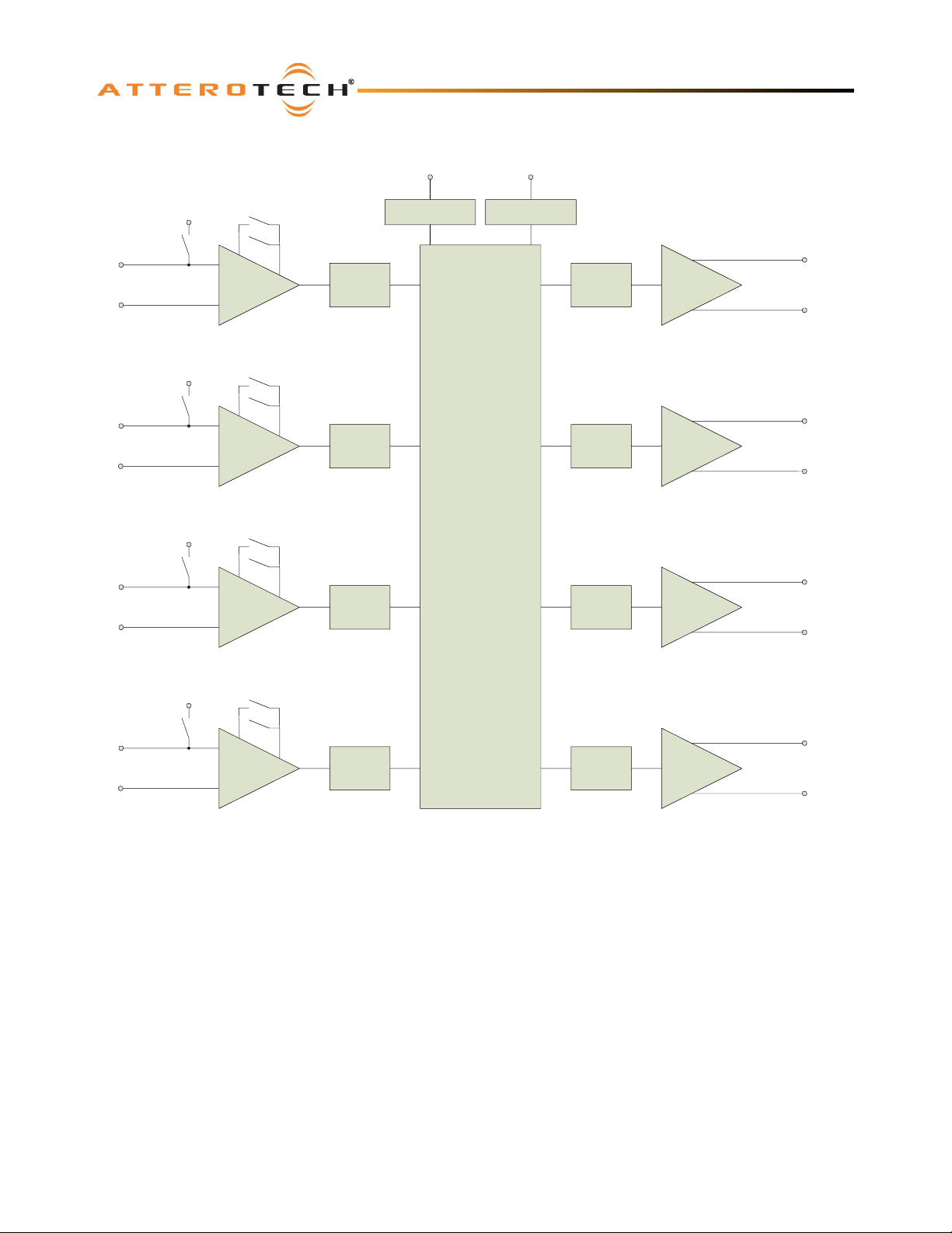
1.3 – System Signal Flow
Selectable Gain
+12V Phantom
Power
0dB, +30dB, +50dB
VoiceBox 4 I/OP
User Manual
RJ45 Conn 3-pin Serial Conn
CobraNet Port RS232 Port
Mic/Line Input
CH1
+12V Phantom
Power
Mic/Line Input
CH2
+12V Phantom
Power
Mic/Line Input
CH2
+12V Phantom
Power
Mic
Preamp
Selectable Gain
0dB, +30dB, +50dB
Mic
Preamp
Selectable Gain
0dB, +30dB, +50dB
Mic
Preamp
Selectable Gain
0dB, +30dB, +50dB
ADC
ADC
ADC
CobraNet Processor
+
Audio DSP
DAC
DAC
DAC
Balanced Line
Output CH1
Balanced Line
Output CH2
Balanced Line
Output CH3
Mic/Line Input
CH4
Mic
Preamp
ADC
DAC
Balanced Line
Output CH4
Figure 1 - Signal Flow within the VoiceBox 4 I/OP
System signal flow is shown in Figure 1. All four input channels utilize discrete preamplifier circuitry for optimum signal to
noise ratio with low distortion. Each preamplifier is equipped with 3 selectable analog gain settings, 0 dB for line level
sources, +30 dB for condenser microphones, and +50 dB for dynamic microphones. Each channel also has selectable +12 V
phantom power for powering most electret or small diaphragm condenser microphones.
After the mic/line preamp stage, the analog signal is converted using a high quality 24-bit/48 kHz A-D converter. After
conversion, the digital signal is then sent to the CobraNet processor and DSP. The DSP applies independent and adjustable
equalization (low cut, low shelf, mid sweep, high shelf, and high cut filters), compression, and gain to each input channel.
A fully configurable thirteen input, twelve output matrix mixer allows the processed input channels to be sent out to the
CobraNet network and/or routed back to the local outputs. The matrix mixer also provides the ability to route audio
received from the CobraNet network to the local outputs and/or be looped back to the CobraNet outputs. A further input
into the matrix mixer is provided from a configurable sine wave generator for testing and diagnostic purposes.
Each of the four local output channels also features five bands of fully adjustable parametric EQ, a high pass filter, a fully
adjustable limiter, additional gain/attenuation and a delay element with up to 20ms of delay. The digital audio is then sent
to a high quality D-A converter. The analog signal is then converted to a balanced line level output and sent to the local
audio output connectors.
Attero Tech LLC 2010 Page 2 614-00008-02
Page 7
VoiceBox 4 I/OP
User Manual
1.4 – Signal Processing
All signal processing after the analog preamplifier circuitry is implemented in the digital domain using powerful 32-bit DSP
hardware and high quality algorithms. All signal processing parameters mentioned are configurable using the Attero Tech
Control Center software.
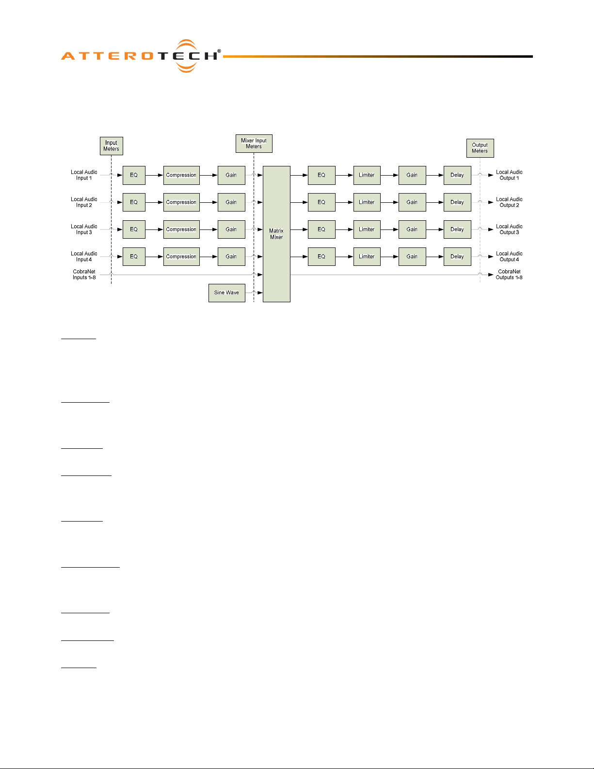
Figure 2 - DSP Architecture
Input EQ
The EQ stage consists of five cascaded filters: A single pole low cut filter, a 2-pole high cut filter, a low frequency shelf filter,
a mid sweep filter, and a high frequency shelf filter. The low and high cut filters both have adjustable frequencies and have
a bypass option. The low frequency shelf filter is set at 400 Hz and has adjustable gain. The high frequency shelving filter
is set at 3 kHz and also has adjustable gain. The midspan equalizer has adjustable center frequency and gain. Gain for
each filter is adjustable from +12 dB to -12 dB.
Compressor
The compressor stage provides full control over the compression ratio, threshold, attack, and release times. A gain
reduction meter is shown also that shows the amount of compression taking place. The compressor function has a bypass
option.
Input Gain
The input gain stage provides an adjustable range from +12 dB gain to -100 dB of attenuation in 1 dB steps.
Matrix mixer
The matrix mixer provides 12 inputs (4 local, 8 CobraNet) and 12 outputs (4 local, 8 CobraNet). There is also an additional
input from an internal sine wave generator. Any mix of local inputs, network inputs and sine wave generator input can be
directed to any of the local or network outputs.
Output EQ
The output EQ stage consists of five cascaded parametric filters and a high pass filter. Each parametric filter has adjustable
gain, bandwidth and frequency and the 2-pole high pass filter has adjustable frequency. Gain for each parametric filter is
adjustable from +12 dB to -12 dB.
Output Limiter
The output limiter provides limiting for each output channel independently. Limiter ratio is fixed at 100:1. Threshold,
attack, and release time parameters are configurable. A gain reduction meter shows the amount of limiting taking place.
The limiter function may be bypassed.
Output Gain
The gain stage provides a range from +12 dB gain to -100 dB of attenuation. Gain settings are adjustable in 1 dB steps.
Output Delay
Each output has its own delay control with up to 20ms of delay available.
Metering
Metering is available from several points in the audio path: Raw local input, Modified local input, Local output. CobraNet
input and CobraNet output.
Attero Tech LLC 2010 Page 3 614-00008-02
Page 8
2– Installation
VoiceBox 4 I/OP
User Manual
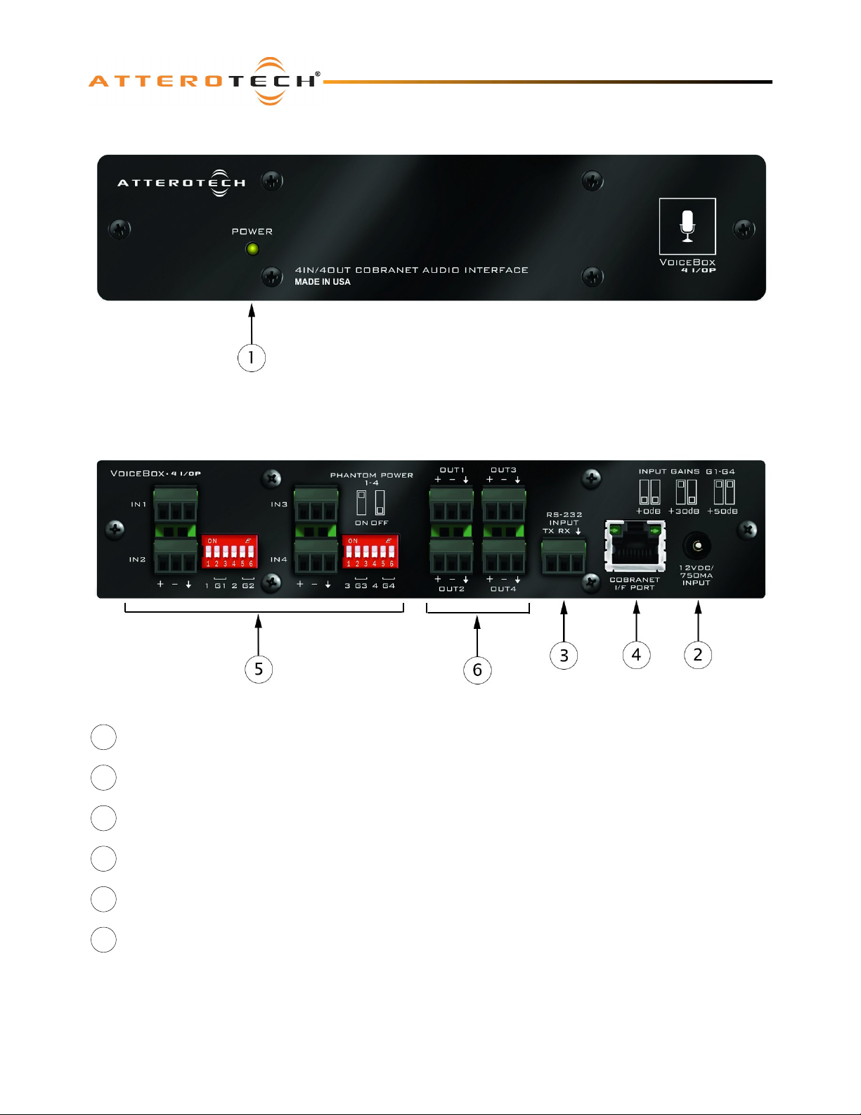
Figure 3 – VoiceBox 4 I/OP Connectors and Indicators
1 Power LED
2 Power Socket – Use with optional 12 V DC wall wart only.
3 Serial Bridge interface connector
4 CobraNet Ethernet interface connector and indicators
5 4 x Balanced audio inputs and associated mic/line and phantom power switches
6 4 x Balanced Audio outputs
Attero Tech LLC 2010 Page 4 614-00008-02
Page 9
VoiceBox 4 I/OP
User Manual
Installation of the VoiceBox is very straight forward. All connections to the VoiceBox should be made before the power is
applied.
o Attach any audio sources that will be used to the inputs. The inputs are balanced so be sure to check what output
type the source is in order to find how to connect it correctly (see section 2.1 – Hardware Connections).
o Select phantom power and/or the level of input gain required as necessary.
o Attach the outputs to the required audio devices. The outputs are balanced so be sure to check what input type
the device requires in order to find how to connect it correctly (see section 2.1 – Hardware Connections).
When powering using PoE:
o Attach the CobraNet I/F port to a spare PoE-enabled port on a PoE switch using a CAT-5 cable. If a midspan
injector is being used, connect a spare input port to the CobraNet network switch using a CAT-5 able, and then
connect the corresponding output port to the CobraNet I/F of the VoiceBox.
When powering using an optional external supply:
o Attach the CobraNet I/F port to a spare port on the CobraNet network switch using a CAT-5 cable.
o Attach the power supply to the power input jack and then power up the external supply.
If all steps are performed correctly, the power light on the front should be lit.
There may also be some activity on the VoiceBox CobraNet I/F LED indicators. With no CobraNet network, the LED on the
right of the CobraNet I/F port will be on. If another active CobraNet device is detected on the network or the Attero Tech
Control Center application or other similar CobraNet application program is active on the network, the left hand LED will be
flashing at a rate around three times per second and the right hand LED may either also flash or remain steady.
2.1 – Hardware Connections
The VoiceBox 4 I/OP accepts and drives either unbalanced or balanced audio devices. Refer to the following diagrams and
instructions for connecting different types of audio devices. Professional grade audio cabling is recommended to achieve
the best audio performance throughout the system.
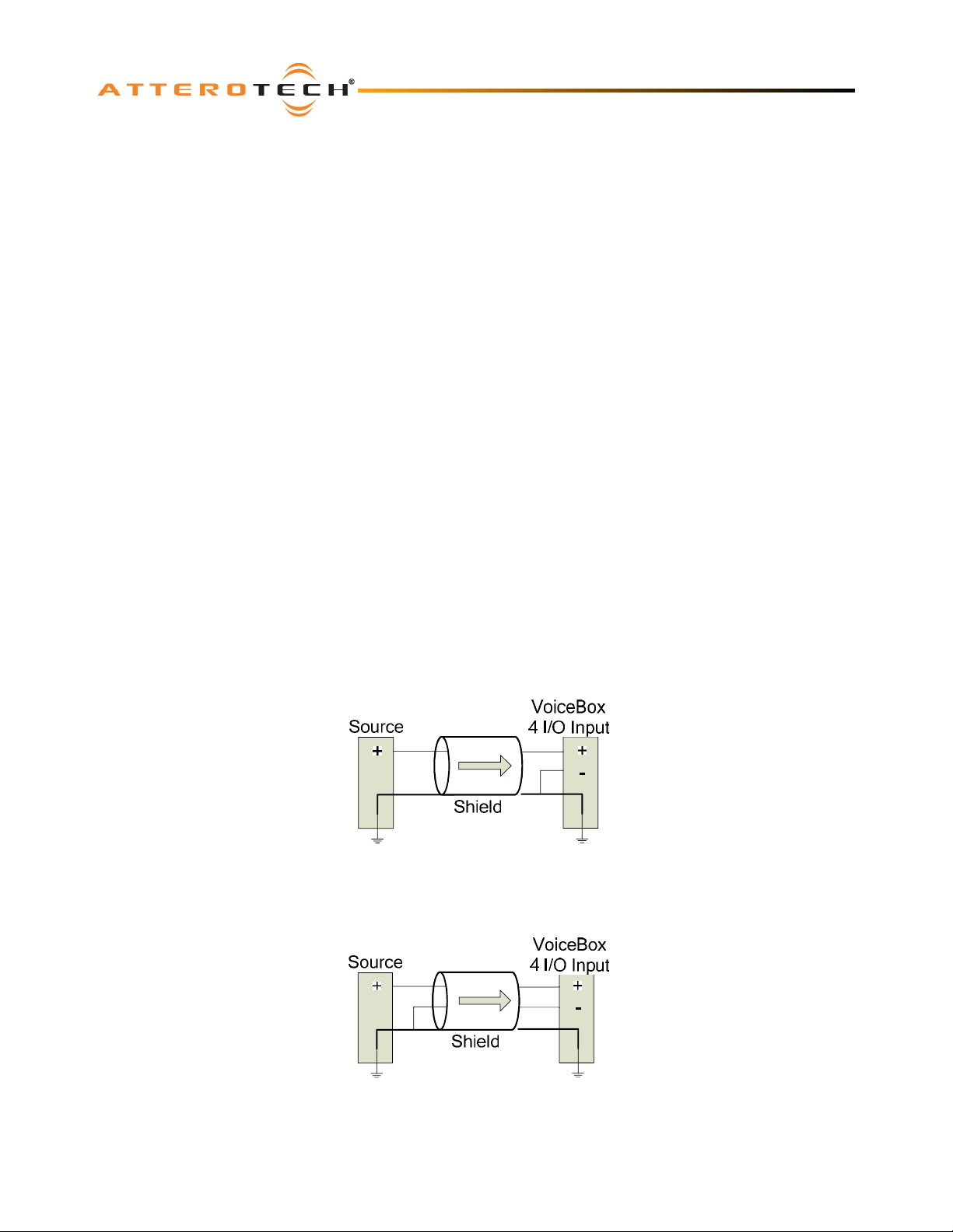
2.1.1 – Input from an Unbalanced Source
To connect a 2-wire unbalanced source to the VoiceBox 4 I/OP, connect the positive output of the unbalanced source to the
positive input of the VoiceBox 4 I/OP. Connect both the source and VoiceBox 4 I/OP input grounds together, and short the
negative input of the VoiceBox 4 I/OP to round at the input of the VoiceBox 4 I/OP.
Figure 4 - 2-Wire Unbalanced Source Connection
To connect unbalanced sources with a 3-wire connection, short the negative conductor to the shield at the source
connection.
Figure 5 - 3-Wire Unbalanced Source Connection
Attero Tech LLC 2010 Page 5 614-00008-02
Page 10
VoiceBox 4 I/OP
User Manual
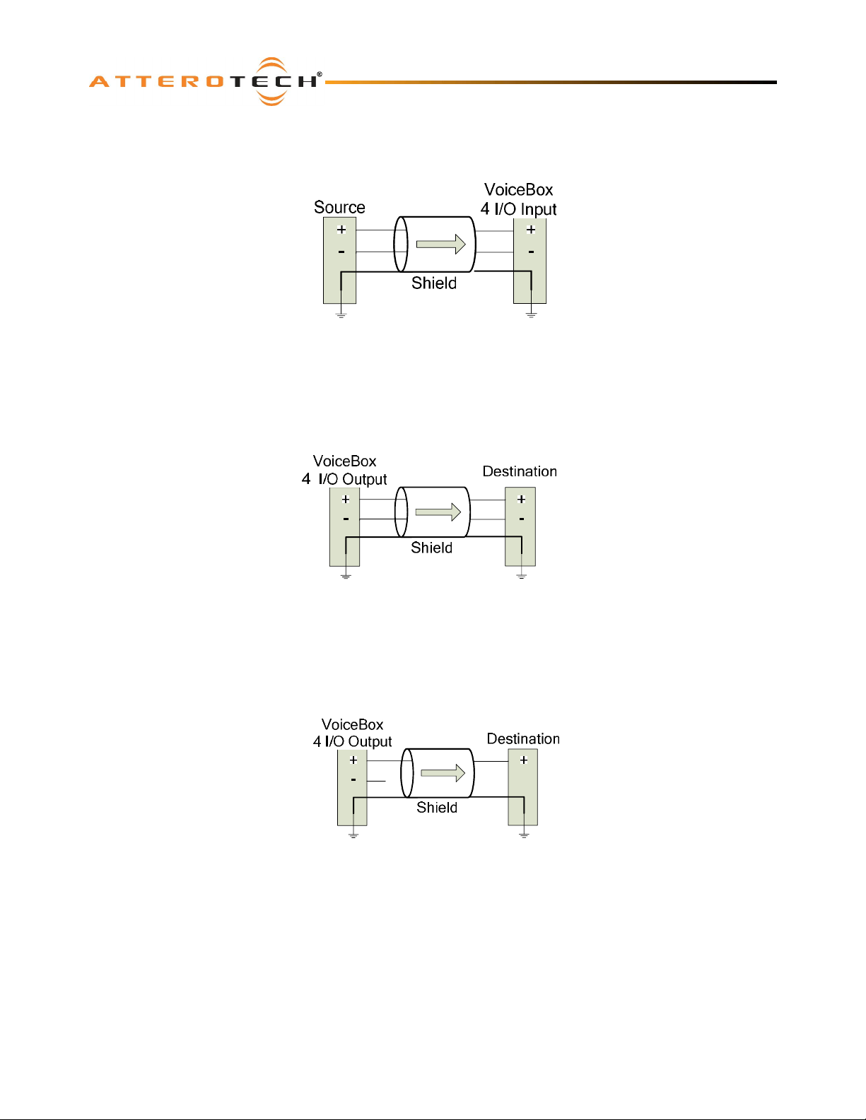
2.1.2 – Input from a Balanced Source
To connect balanced sources to the VoiceBox 4 I/OP, connect positive output to positive input, negative output to negative
input, and connect the grounds together through the cable shield.
Figure 6 - Balanced Source Connection
2.1.3 – Output to a Balanced Destination
To connect to a balanced input on a destination device, connect the positive, negative, and ground connections of both the
VoiceBox 4 I/OP output to the destination input respectively.
Figure 7 - Out to Balanced Destination Connection
2.1.4 – Output to an Unbalanced Destination
To connect the VoiceBox 4 I/OP outputs to a 2-wire unbalanced input, connect the positive output to the destination’s
positive input and connect the grounds together through the cable shield. Leave the VoiceBox 4 I/OP negative output
floating.
Figure 8 – Output to Unbalanced Destination
2.1.5 – RS-232 Serial Bridge Port
The RS-232 Serial Bridge Port located on the rear panel of the VoiceBox 4 I/OP implements RX, TX, and GND connections.
The 3-Pin de-pluggable connector can be used to interface with other RS-232 enabled equipment - for example, a computer
serial port. The TX signal is an output from the VoiceBox 4 I/OP and the RX signal is an input. Connections to other RS-232
hardware should be made accordingly.
Note: The RS-232 port does not communicate locally with the VoiceBox 4 I/OP, but is a conduit to other devices on the
CobraNet network. The Serial Bridge feature of CobraNet allows serial data to be sent across the network to other serialenabled devices. This feature is useful for extending control data to remote locations. The settings for the serial bridge can
be configured using the Attero Tech Control Center software.
Attero Tech LLC 2010 Page 6 614-00008-02
Page 11
VoiceBox 4 I/OP
User Manual
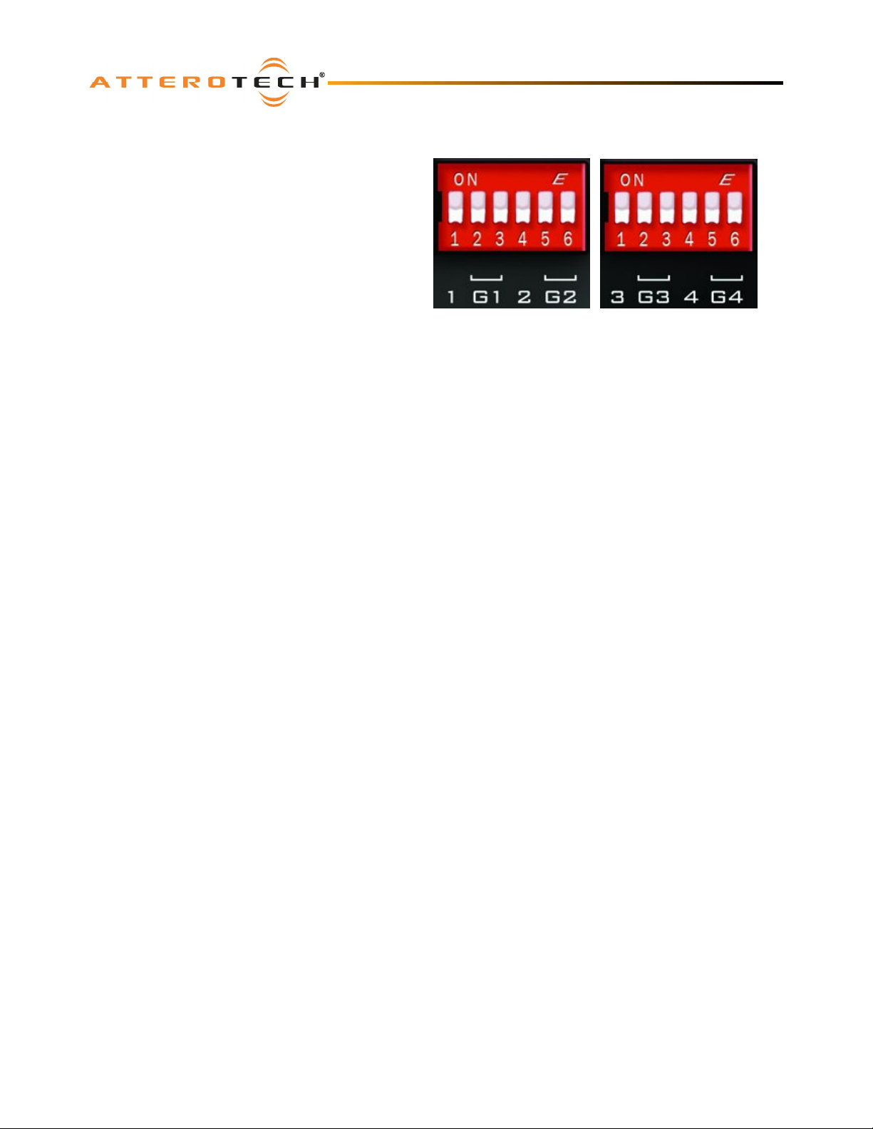
2.2 – Phantom Power and Gain Switches
The VoiceBox has the ability to provide phantom power
and input gain on each input. Switches are provided for
controlling both these features independently on each
input. G1 to G4 are 4 groups of switches controlling
input gain on inputs 1 to 4 respectively. The remaining
four switches, number 1 through 4 are the four phantom
power switches for inputs 1 to 4 respectively.
The two gain switches per input provide a choice of line
level input (0 dB), +30 dB gain, or 50 dB gain. To use a
line level input, ensure both gain switches for that
channel are in the down position. To set +30 dB of input
gain, move the left hand switch of the gain group to the
up position. To set the input gain to 50 dB, move both
switches in the gain group to the up position.
Phantom power enables the VoiceBox 4 I/OP to provide +12 V DC at very low current over the audio input lines to power an
active microphone. With the switch in the down position, (as they all are in Figure 9), phantom power is not enabled. Move
the switch to the up position to activate it.
Note: The positions of the switches for both gain and phantom power are also shown on the back panel itself for easy
reference.
Figure 9 - Gain and Phantom Power switches
Attero Tech LLC 2010 Page 7 614-00008-02
Page 12
VoiceBox 4 I/OP
User Manual
3 – Software Installation and Setup
The Attero Tech Control Center application should be used to examine and modify device configuration. This includes not
only the standard CobraNet features such as audio routing but also the device specific controls of the signal processing
blocks the VoiceBox uses.
Refer to the Attero Tech Control Center User’s Guide for installation and setup instructions.
Note: Other third party software may be used to set up audio routing but the signal processing blocks can only be controlled
using the Attero Tech Control Center application.
3.1 – DSP Overview
The following section describes the operation and controls available in VoiceBox 4I/O PoE interface V1.1.1.133.
Note: Control Center version 1.0.2.12 and later shows the version number for each interface on the About form. Please be
aware of the version of interface being used, as a different version of the interface may contain different controls and have
different operation.
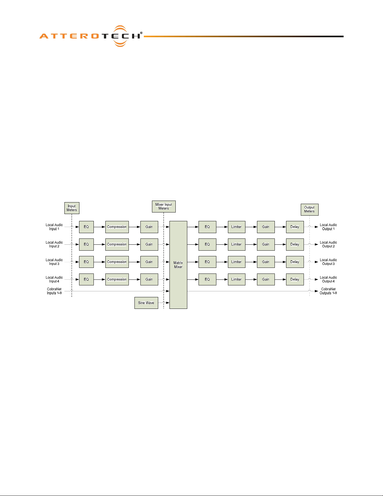
The VoiceBox 4 I/OP utilizes available DSP resources within its CobraNet device to provide audio signal processing (see
Figure 10). The local inputs of the VoiceBox are fed through a Compressor stage, an EQ stage, and a Gain stage. The
processed signals are then presented along with eight incoming channels of CobraNet audio to a matrix mixer. After the
Mixer stage, the local outputs pass through a Limiter stage before being fed to the D/A convertors.
Figure 10 – VoiceBox 4 I/O DSP Architecture
The interface for the VoiceBox 4 I/OP allows configuration of all aspects of the signal processing blocks shown in Figure 10.
The processing is split into three sections: Input Processing, Matrix Mixer, and Output Processing.
The input processing affects signals input into the local inputs on the VoiceBox only. The Matrix Mixer takes the results of
the input processing, CobraNet audio received by the VoiceBox and also an internally generated sine wave and mixes them
together to produce four local output channels and eight CobraNet output channels. The CobraNet output channels are
ready for immediate transmission elsewhere with no further processing. However, the local output channels are then
subjected to the output processing before being passed to the outputs themselves.
Attero Tech LLC 2010 Page 8 614-00008-02
Page 13
3.2 – Input Processing
VoiceBox 4 I/OP
User Manual
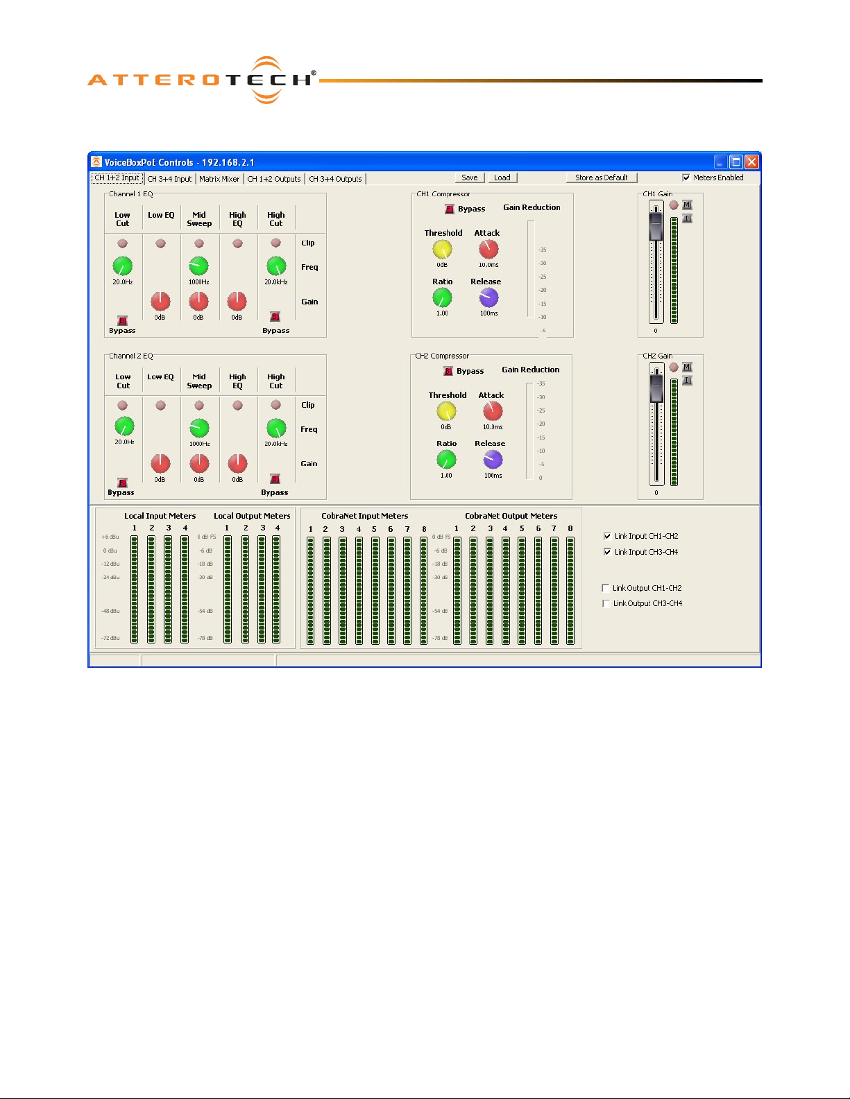
Figure 11 – Local Input Channel Processing for Channels 1 and 2
Figure 11 shows the general layout of the form. It contains five tabs. The first two tabs are dedicated to local input
processing with two input channels on each tab. The third is dedicated to the Matrix Mixer. The final two tabs are
dedicated to local output processing with two output channels on each tab.
For controls that utilize either a control knob or a fader, the value can be altered by clicking and holding the left mouse
button down on the control and dragging the mouse forward or backward to alter the value upward or downward
respectively.
The value can also be typed in if the controls have their value shown underneath. Clicking on the control will highlight the
complete text and typing a new value will overwrite the current text. The controls accept shorthand notation such as 10k
for 10000 and 10m for 0.01. They will also accept the correct unit if entered, though it is not necessary to include it. Once
the required value is entered, press the Enter key to complete the process and accept the new value. If a valid number is
entered, the control will change to the newly entered number or as close to it as the control’s range allows. The control will
revert back to its previous value if an invalid number is entered.
Notes:
o If the Enter key is not pressed after entering a new value and a different control is selected, the control that was
being edited will revert to its previous value.
o When a fader or knob control value is changed, its value is sent to the device only once the Enter key is pressed or
the mouse is released.
The other type of control is an indicator button. These are either grey for off or colored (red, green, or yellow) for on. To
change the state of the button from on to off or from off to on, left-click on it.
Attero Tech LLC 2010 Page 9 614-00008-02
Page 14
3.2.1 – Input EQ
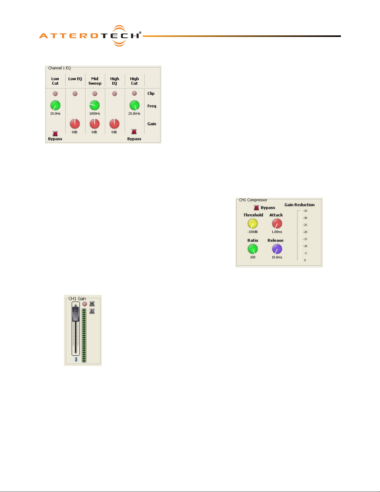
The input EQ consists of several cascaded filters: a low and high cut,
a low EQ, a mid sweep and a High EQ.
The low cut is a 12dB / Octave filter with adjustable frequency. The
high cut is a 6dB / Octave filter with adjustable frequency. The low
EQ is a low shelf filter set at 400 Hz with adjustable gain. The mid
sweep is a parametric EQ with a fixed bandwidth of 1 Octave but
adjustable frequency and gain. The high EQ is a high shelf filter set
at 3 kHz with adjustable gain.
In each case the frequency can be adjusted from 20 Hz to 20 kHz
and the gain controls work from -12 dB to +12 dB. The high cut and
low cut filters also have a bypass facility which, when active, will
cause that filter to be bypassed and have no affect on the audio
Figure 12 - Input EQ Controls
signal.
Each stage also has a clipping LED which lights red when clipping
occurs.
3.2.2 – Input Compressor
The Input Compressor consists of four controls, a Bypass button, and a
Gain Reduction meter.
VoiceBox 4 I/OP
User Manual
The Bypass button allows the compressor to be completely bypassed and
its settings ignored. Click on the button to toggle the state of the
bypass. If the red indicator is on, the bypass is activated.
The Threshold value ranges from -100 dB to 0 dB. The Ratio value ranges
from 1:1 to 100:1. The Attack value ranges from 1ms to 1s and the
Release value ranges from 10 ms to 30 s.
If any compression takes place, the Gain Reduction meter will show the
amount of signal attenuation.
3.2.3 – Input Gain
The Input Gain control allows the overall level of the signal to be adjusted before it is
fed into the mixer.
The fader sets the gain from -100 dB to +12 dB. The meter alongside shows the
current level after all the input processing has taken place, including the gain factor.
There is also a clipping LED.
The gain control also has two toggle indicators. The upper one marked with an “M” is
the “Mute” button. The lower button marked with an “I” is the “Polarity Invert” button.
Figure 14 - Input Gain Controls
Figure 13 - Input Compressor Controls
Attero Tech LLC 2010 Page 10 614-00008-02
Page 15
VoiceBox 4 I/OP
User Manual
3.3 – Matrix Mixer
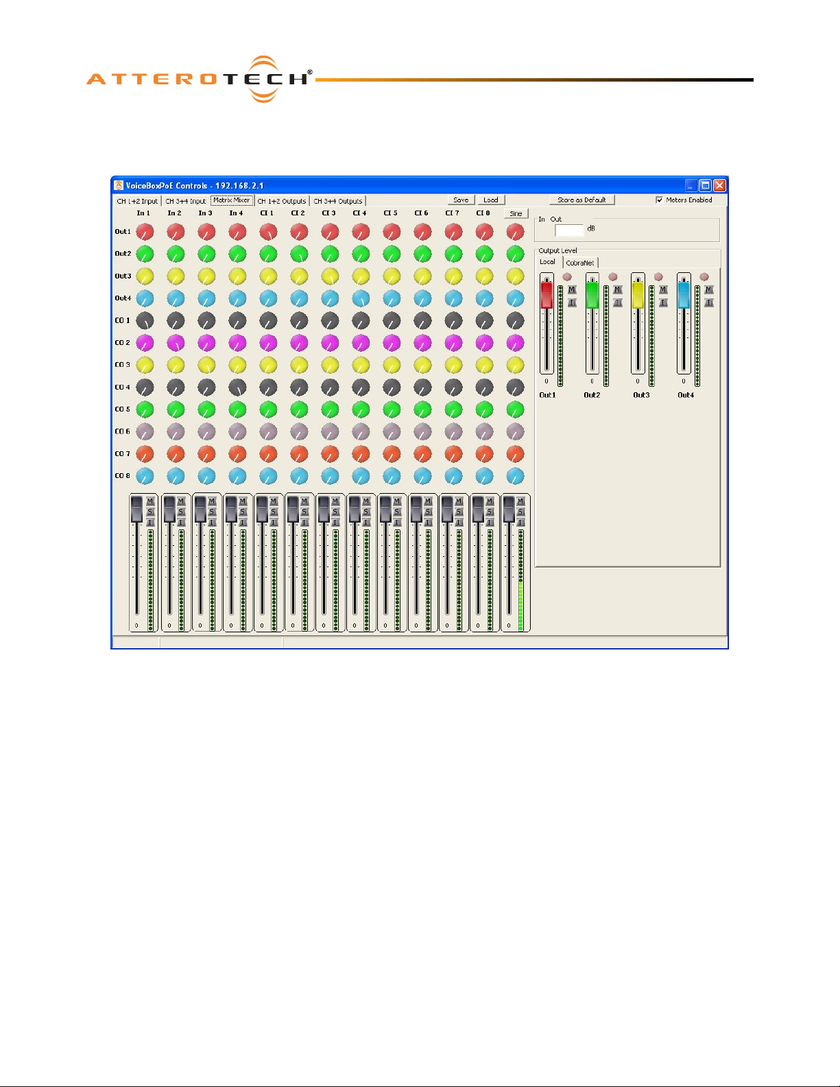
The Matrix Mixer (shown in Figure 15) combines a number of controls. Each of the Local and CobraNet inputs are shown in
columns with the send controls running across in rows.
Figure 15 – Matrix Mixer Tab of VoiceBox Interface
3.3.1 – Matrix Mixer Input Controls
Each input has its own set of controls at the bottom of the column. There is an input fader that ranges from -100 dB to 0 dB
as well as “Mute”, “Invert” and “Solo” buttons.
Note: The Matrix Mixer input meters can only show the levels prior to entering the Matrix Mixer. Changing any of the Matrix
Mixer input controls will not affect the level of the accompanying input meter.
3.3.2 – Crosspoint Controls
Each input has a set of corresponding crosspoint knob controls which feed the audio (or a degree of it) to a particular
output. Each knob control ranges from -100 dB to 0 dB. Unlike other knob controls elsewhere on the form, there is no text
below each control. Instead, there is an edit box at the top right hand corner of the matrix. A single left click on a
particular crosspoint will show the control’s value in the edit box. This can also be used to type in a specific value for the
selected control.
Attero Tech LLC 2010 Page 11 614-00008-02
Page 16
3.3.3 – Matrix Mixer Output Controls
VoiceBox 4 I/OP
User Manual
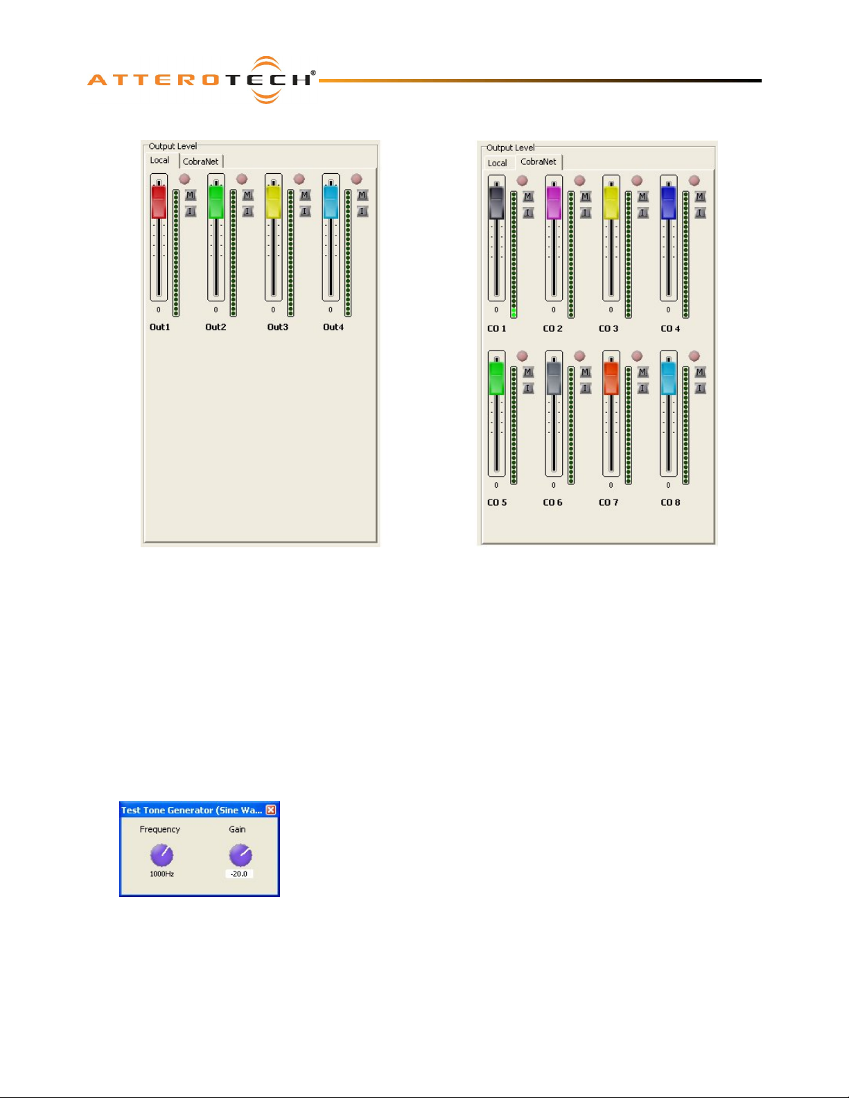
Figure 16 - Matrix Mixer Output Controls: Local (left) and CobraNet (right)
The output section of the Matrix Mixer is split into two tabs. The first tab shows the local outputs. The second tab shows
the CobraNet outputs.
The mixer sends are colored according to the corresponding output level fader. The output faders range from -100 dB to
+12 dB.
There are also a number of complementary controls: a clipping LED, a “Mute” button, and a “Polarity Invert” button.
The meters on the CobraNet outputs show the output levels from the Matrix Mixer that are available to the network.
However, the meters on the local outputs show the levels after any output processing has been applied rather than the
direct output of the matrix mixer.
3.3.4 – Sine Wave Generator
The Test Tone or Sine Wave Generator can be used to help diagnose problems.
It is generated internally by the on-board DSP of the VoiceBox. The output of
the generator is fed into the Matrix Mixer (furthest input to the right). Above
the column is the “Sine” button which, when clicked on, accesses the Sine Wave
Control form. The form has a Gain control to set the amplitude of the signal
between -100 dB and 20 dB. There is also a Frequency control to set the
frequency of the test tone which ranges from 20 Hz to 20 kHz.
Figure 17 - Sine Wave Control Form
Attero Tech LLC 2010 Page 12 614-00008-02
Page 17
VoiceBox 4 I/OP
User Manual
3.4 – Output Processing
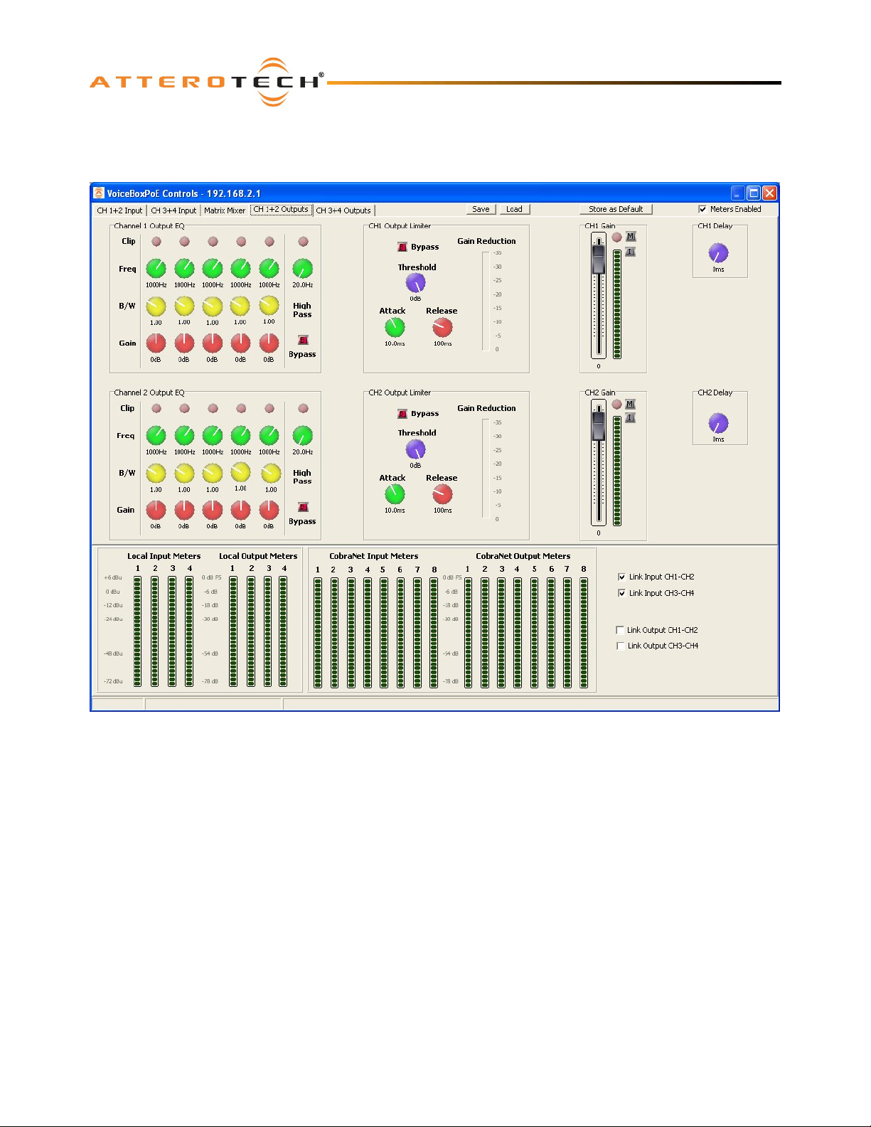
The audio for the local outputs is passed from the matrix mixer to the output processing stage. Figure 18 below shows the
form for outputs 1 and 2. The layout is identical for outputs 3 and 4.
Figure 18 - Local output processing for Channels 1 and 2
Attero Tech LLC 2010 Page 13 614-00008-02
Page 18
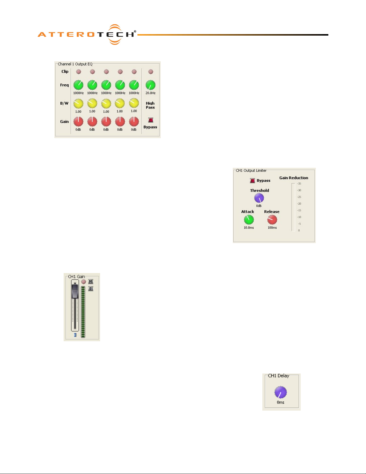
3.4.1 – Output EQ
The output EQ stage has five cascaded bands of parametric EQ
followed by a high pass filter. Each parametric EQ has
adjustable frequency (20 Hz to 20 kHz), bandwidth (0.1 to 3.0)
and gain (-12 dB to +12 dB). Each stage has it’s own clip LED to
warn if the signal at the stage is clipping or not.
The high pass filter is a 12 dB / Octave filter with adjustable
Frequency from 20 Hz to 20 kHz. This filter also has a clip
indicator. It also has a bypass facility that, when active, will
allow the audio to ignore this filter.
Figure 19 - Local Output EQ Controls
3.4.2 – Output Limiter
The output limiter has four controls are available for each output.
The bypass button allows the limiter to be completely bypassed and its
settings ignored. Click on the button to toggle the state of the bypass. If
the red indicator is on, the bypass is activated.
VoiceBox 4 I/OP
User Manual
The remaining controls control the specific aspects of the limiter.
The threshold control ranges from -100 dB to 0 dB, the attack control
ranges from 1 ms to 1 s, and the release control that ranges from 10 ms
to 30 s.
There is also a gain reduction meter to given an approximate indication
of the amount of limiting that is actually taking place.
Figure 20 - Local Output Limiter Controls
3.4.3 – Output Gain
The Output Gain control allows the overall level of the signal to be adjusted before
it is fed to the local outputs
The fader sets the gain from -100 dB to +12 dB. The meter alongside shows the
current level after all the input processing has taken place, including the gain
factor. There is also a clipping LED.
The gain control also has two toggle indicators. The upper one marked with an “M”
is the “Mute” button. The lower button marked with an “I” is the “Polarity Invert”
button.
Figure 21 - Output Gain Controls
3.4.4 – Output Delay
The delay control adds buffering to delay the audio signal. If the control is set to 0, the
control is essentially bypassed.
A maximum delay of up to 20 ms can be added in total.
Figure 22 - Output Delay
Attero Tech LLC 2010 Page 14 614-00008-02
Control
Page 19
VoiceBox 4 I/OP
User Manual
3.5 – General Controls
3.5.1 – Stereo Linking
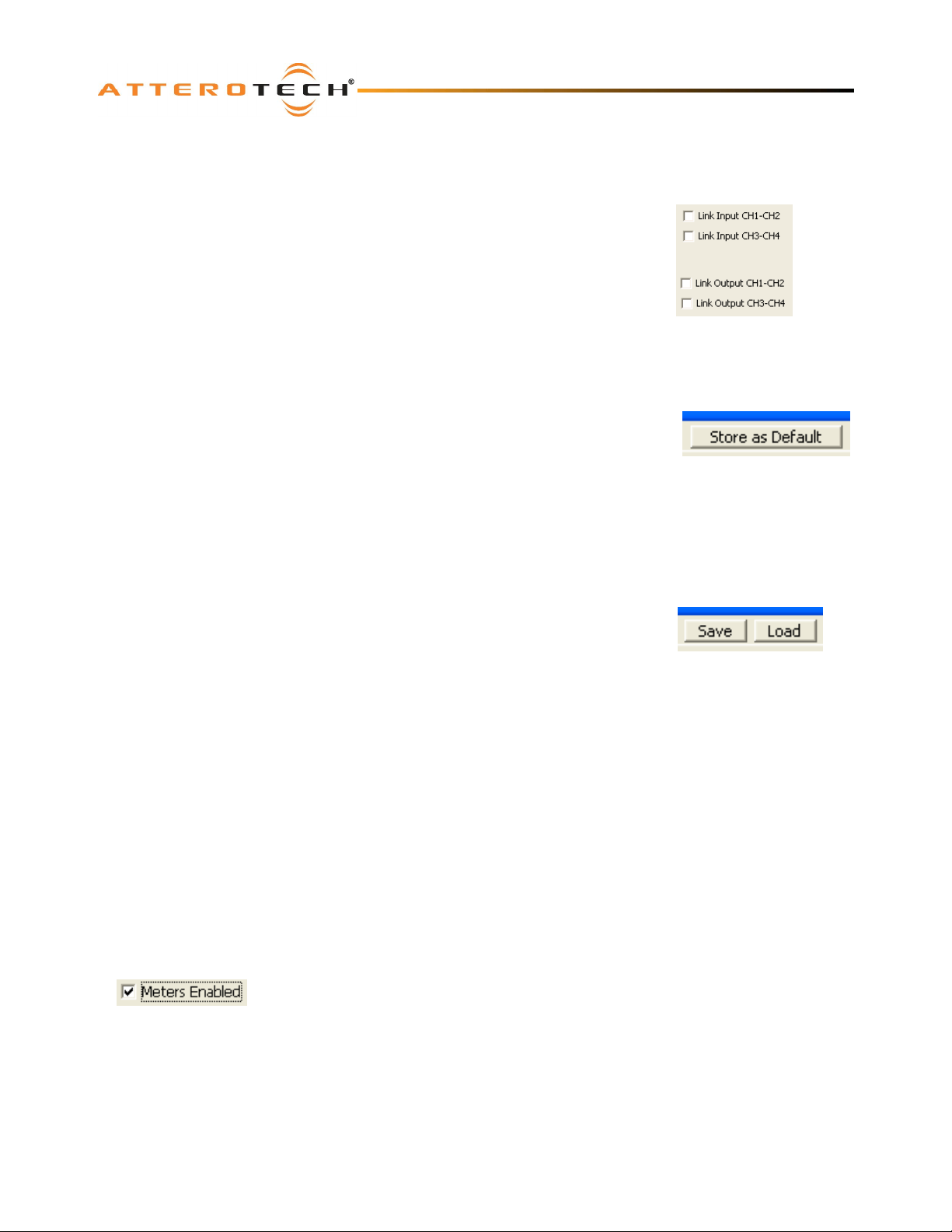
The local input channel controls have the option to be linked together to form stereo
pairs. This same feature, called stereo linking, is also available for the local output
channels also. Channels 1 & 2, may be linked and channels 3 & 4 may be linked. Both
links may be active at one time. There is no provision for the settings in channels 3
and 4 to be linked in any way to inputs 1 & 2 and vice versa.
Linking the channels in this way will mean that any changes to one channel will be
reflected in the other. When linking takes place, depending on which channels are
linked, the parameters for channel 2 will change to match those set for channel 1 or
the parameters for channel 4 will change to match those set for channel 3. This
happens as soon as the link is enabled. From then on, all changes to one channel will
update the other channel and vice versa.
3.5.2 – Store New Power-up Default
Although the settings of the controls are applied immediately to the controlled device, the
values are not permanent and will be lost if the device is powered down. In order to ensure
that the changes are retained, they must be committed to non-volatile memory. Clicking on
the Store as Default button on the device setup form commits the current settings in the
device to memory.
Note: This operation takes a few seconds to complete and no other actions can be done
until it is complete. The status bar will show the progress of operation and also a message once the operation is complete.
Figure 23 - Stereo Link
Controls
Figure 24 – Store as
Default Button
3.5.3 – Saving / Loading VoiceBox Configuration Presets
Once all the parameters have been set correctly, the complete configuration can be saved
to a file so the settings may be easily transferred to another VoiceBox. Click the Save
button at the top of the form (as shown in Figure 25) to initiate this. The Configuration
Save dialog will appear allowing you to select a folder and a file name. Clicking on OK
will save the configuration using the chosen filename in the chosen location. The
filename will, by default, use a .DCF extension.
Once the save is complete, the application will ask if the current device should have its
configuration “saved as default” to ensure that it will power up with the parameters just saved. Click “Yes” to confirm the
save or “No” to skip it. A final message will then appear to confirm the save is complete.
To load a previously saved configuration, click the Load button. The Load Configuration dialog will appear so the desired
configuration file can be located. Locate and select the file to be loaded and click OK. A confirmation message will then be
shown as a reminder that the current device configuration will be overwritten. Click “Yes” to continue.
Once correctly loaded, the application will ask if the new configuration just loaded to the device should be saved as the
default. Click “Yes” to store the loaded parameters as the new defaults for power up. Click “No” to skip.
Note: The saved configuration is device specific so only VoiceBox configuration files can be loaded into a VoiceBox. The
revision of VoiceBox firmware is also taken into account. A warning will be shown and the file will not be loaded if either the
device type or the firmware revision does not match the device being set up.
Figure 25 - Save/Load
Buttons
3.5.4 – Metering
The VoiceBox interface can constantly monitor audio levels while the interface is open. Meters
on the input tabs and on the Matrix Mixer tab show various audio levels whilst numerous
clipping LEDs advise if the digital signal gets too large.
Figure 26 - Meters
Enabled Checkbox
Click the Meters Enabled check box to toggle the metering on or off.
The metering function polls the VoiceBox numerous times a second to get constant updates
for the meters and clip LEDs, but doing so creates an increased amount of network traffic. If
this additional traffic becomes a problem or the metering is not required, it can be turned off.
Note: The meter and clip LED monitoring is only active whilst the VoiceBox interface is open. Metering starts every time the
VoiceBox interface is opened and any active metering ceases as soon as the interface form is closed.
Attero Tech LLC 2010 Page 15 614-00008-02
Page 20
VoiceBox 4 I/OP
User Manual
4 – Troubleshooting
4.1 – Checking the Network Connection
The CobraNet network connection can be diagnosed by noting the status of the LEDs just above the Ethernet connector on
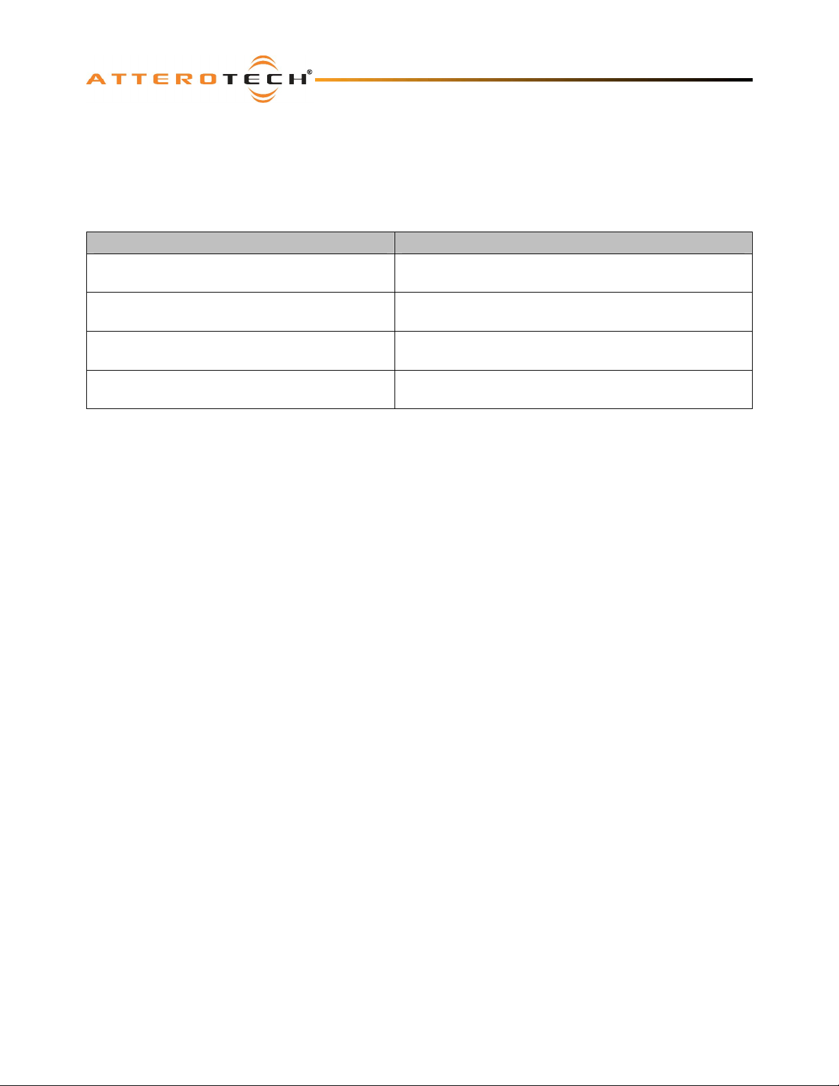
the VoiceBox. These LEDs will be on, off, or flashing depending on the current state of the network connection. Below is a
table showing the states of the LEDs and what device status they represent.
LED status Device Status
Left LED on permanently
Right LED off
Left LED on permanently
Right LED on but flashes off every 4 seconds
Left LED on permanently
Right LED flashing 3 times a second
Left LED on flashing 3 times a second
Right LED flashing 3 times a second
Table 1 - CobraNet Interface LED Status
No Ethernet Connection
Ethernet connected but no devices found
Connected and CobraNet devices found
Device is a performer
Connected and CobraNet devices found
Device is the conductor
4.2 – Common Faults
Below are some common faults. Accompanying each one is a list of the most common solutions. While the lists of solutions
are not exhaustive, they represent the majority of the likely failures.
The VoiceBox does not show up in Control Center.
o If using PoE, check the VoiceBox is attached to a PoE-enabled port on a switch or the output port on a midspan
injector and the power light on the switch/injector is on.
o If using the optional wall wart, Check power is supplied and the power light is on.
o Ensure the PC is running Windows 98SE or later (Windows 95 is not suitable).
o If running Vista, ensure a Vista compatible version of Control Center is running (1.1.0 onwards).
o Check the Ethernet cable is correctly connected.
o If connected to a switch ensure the link indicator is lit and activity flashes at least occasionally. If not, ensure the
correct type of cable is used for the switch. Some switches require standard patch cables. Others can use
standard or crossover cables.
o If connected directly to a PC, ensure the Ethernet cable is a crossover type.
Attero Tech LLC 2010 Page 16 614-00008-02
Page 21
VoiceBox 4 I/OP
User Manual
5 – ARCHITECTS & ENGINEERS SPECIFICATION
The CobraNet interface unit shall provide four mic/line analog inputs on rear panel pluggable 3-pin barrier strips. Selectable
gain of 0 dB, +30 dB, +50 dB, and +12 V phantom power shall be provided on rear panel DIP switches for each analog input
channel. The internal analog to digital signal conversion shall be performed at 16, 20, or 24-bit resolution with a sampling
frequency of 48 kHz. Eight channels of CobraNet inputs and eight channels of CobraNet outputs are supplied via the rear
panel RJ-45 connector. Four channels of balanced line-level outputs shall be provided on the rear panel pluggable barrier
strips. Interface power shall be provided by either an 802.3af compliant PoE network switch or a +12 V DC external power
source.
The CobraNet interface shall provide DSP capabilities for independent channel gain, equalization and compression on all
four local input channels. Each local output channel shall have DSP capabilities for equalization, output limiting, gain, and
delay. The DSP shall also provide a fully configurable 13-input, 12-output matrix mixer with an input from a configurable
sine wave generator.
The CobraNet Interface shall be compatible with Attero Tech Control Center software for flexible control and monitoring in
system applications. The CobraNet Interface shall include a UL listed power source. The CobraNet Interface shall be
compliant with the RoHS directive.
The CobraNet Interface shall be the Attero Tech VoiceBox 4 I/OP.
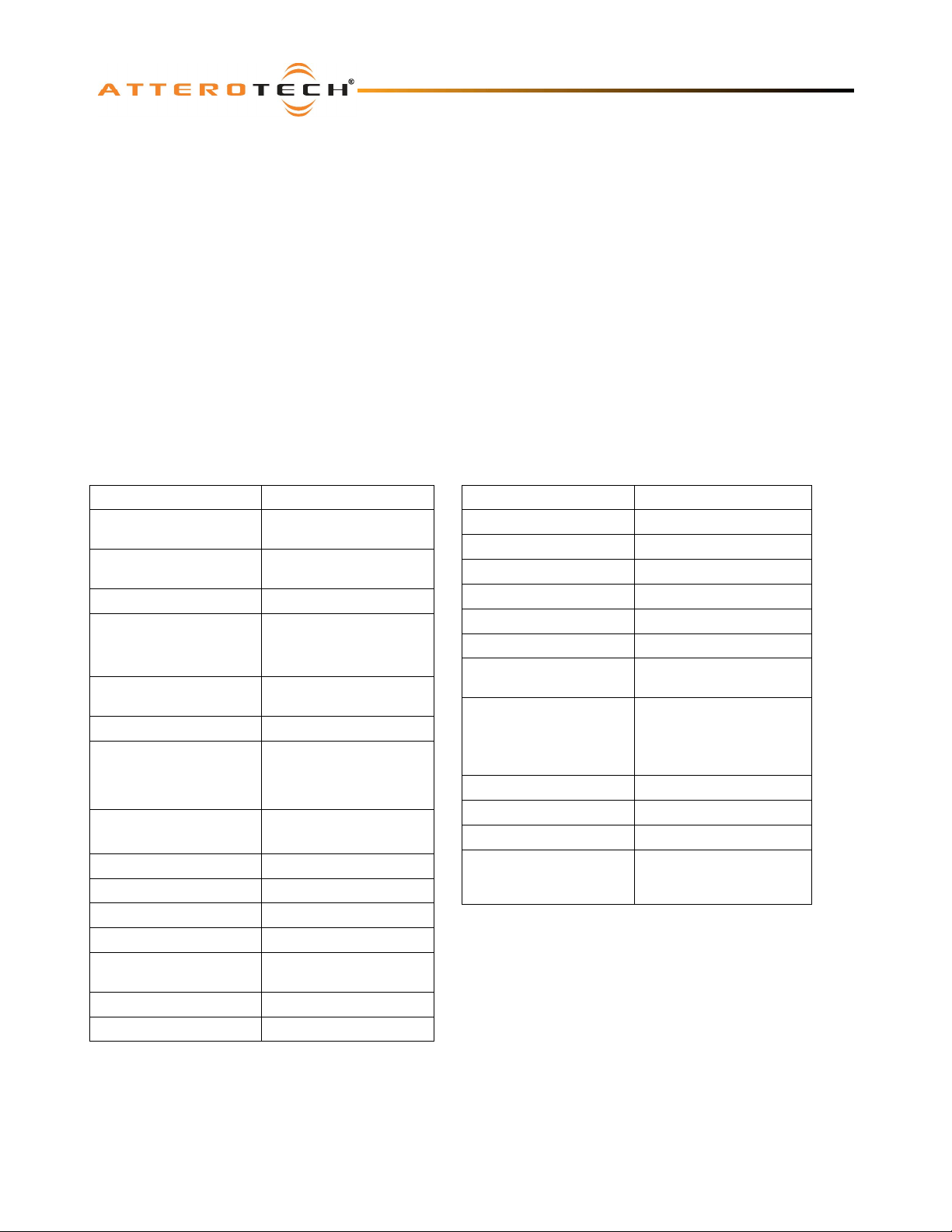
5.1 – Device Specifications
Audio Inputs
Gain:
Input Type:
Input Impedance: > 1.5K ohms, any gain
Maximum Input Levels:
Phantom Power:
Audio Outputs
Output Type:
Output Impedance:
Maximum output level: +10 dBu
Audio Performance:
EIN: -128 dBu
Noise: < -86 dBu @ 0 dB gain
System THD+N:
Frequency Response 20 Hz – 20 kHz, +/- 1 dB
Sample Rate 48 kHz only
Selectable 0 dB, +30 dB,
+50 dB
Balanced and RF filtered
3-pin pluggable
+9 dBu @ 0 dB gain,
-23 dBu @ +30 dB gain,
-42 dBu @ +50 dB gain
+12 V, selectable per
channel
Balanced 3-pin pluggable
with automatic muting
upon loss of CobraNet
signal
200 ohms balanced,
100 ohms unbalanced
< 0.05% at any gain input
signal 3 dB below max
CobraNet Network
Physical Level: Standard Ethernet
Connector: Single RJ-45
Cable Quality: CAT-5
Transmission Speed: 100 Mbps
RS-232 Port
Physical Levels: Standard RS-232
Connector:
Power Requirements
Power Consumption 11 Watts maximum
Dimensions 1.5” H x 7.25” W x 6.5” D
Weight 27 oz, 760 g
Compliance
3-Pin pluggable Phoenix
style
Class 2 802.3af PoE PD
Compliant
or
Optional 12 V DC @ 1A
RoHS, UL Listed power
source, FCC Part 15 Class
A Compliant
Attero Tech LLC 2010 Page 17 614-00008-02
Page 22
VoiceBox 4 I/OP
User Manual
APPENDIX A – Introduction to CobraNet
CobraNet is an audio networking technology for delivery and distribution of real-time, high quality, uncompressed digital
audio using a standard Ethernet network. It is implemented using a combination of hardware, firmware, and the CobraNet
protocol.
Unlike other audio networking or distribution technologies, CobraNet is a true network and exists on standard Ethernet
networks using standard Ethernet hardware. Since it is a true network, audio routing is highly flexible between network
nodes and can be used in a variety of audio distribution applications.
In addition to the high degree of routing flexibility that CobraNet provides, the technology also incorporates the ability to
monitor and control CobraNet devices remotely. This is a key feature that is highly important in fixed installation
applications where the audio distribution equipment may not be readily accessible. All CobraNet devices on the network
can be controlled and monitored from a central location by sending control commands and monitoring device specific
parameters.
CobraNet provides this capability by implementing Simple Network Management Protocol (SNMP). SNMP is a standard
protocol typically used for monitoring network devices such as Ethernet switches. In the case of CobraNet, it allows users to
communicate with any CobraNet device using standard SNMP tools or a customized user interface designed specifically for
CobraNet, such as Attero Tech’s Control Center application.
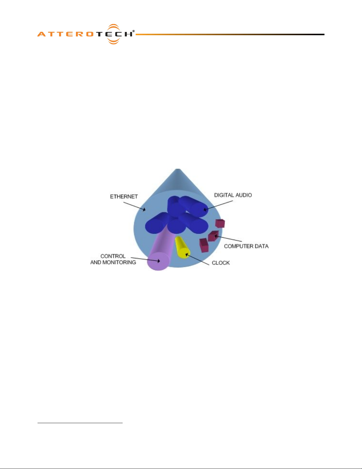
The figure above represents the types of data that coexist on a CobraNet network.
Before a CobraNet system can be configured, it is important to first understand how CobraNet distributes audio between
devices.
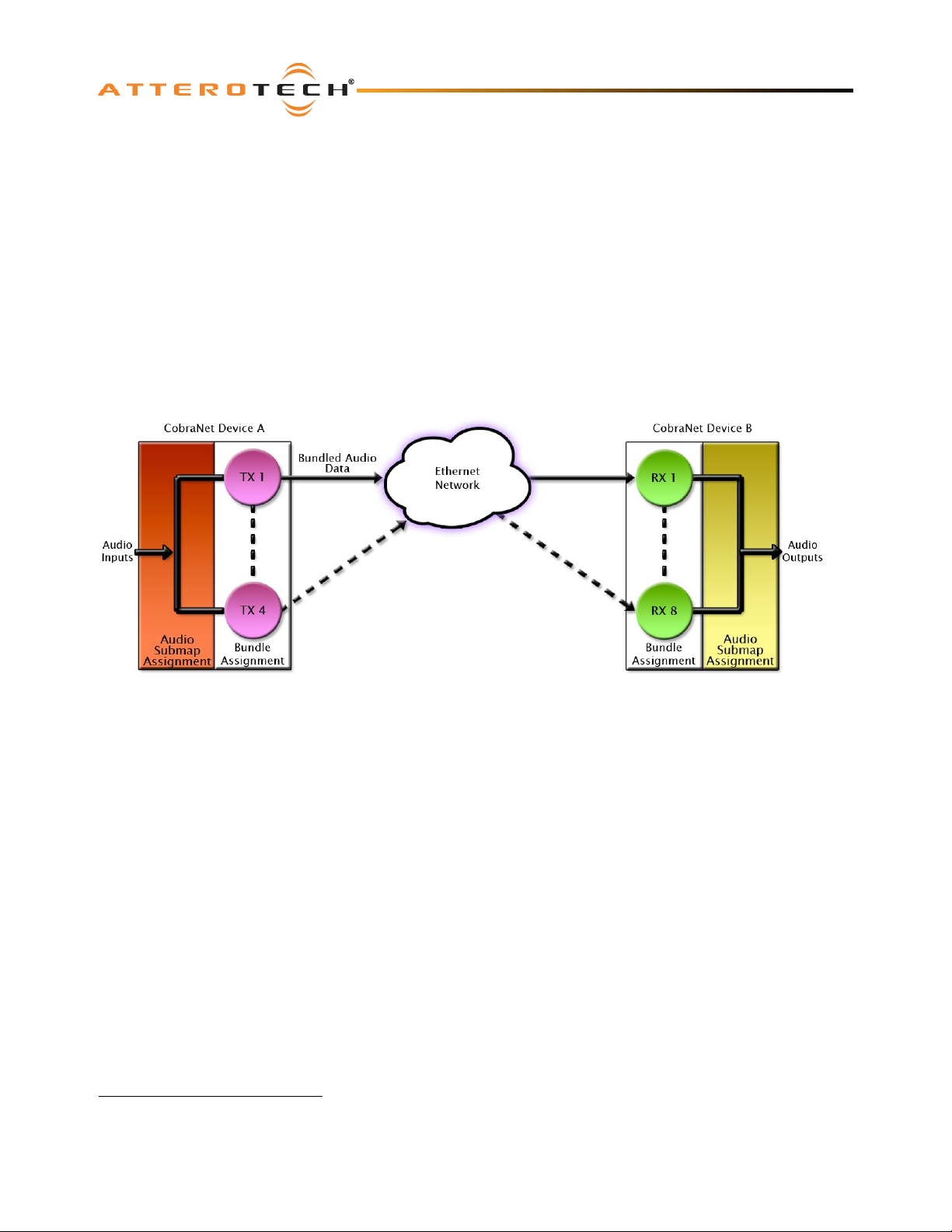
Audio is sent in "bundles" on a CobraNet system. Each bundle is capable of holding up to 8 logical audio channels. Every
CobraNet device has a number of bundle transmitters and bundle receivers. These transmitters and receivers are the
mechanism used to send and receive bundles between devices.
For a transmitted bundle, audio may be sourced either directly from the local audio inputs of the device or from internal
audio via the on-board DSP
sourced from the local device inputs, sent from another CobraNet device or even generated by the DSP itself. Combinations
of the local or internal audio may exist within a bundle in any order. Additionally, a single audio source in a device may be
used multiple times in a single transmitter bundle or across multiple transmitter bundles.
For a received bundle, the received network audio may be routed directly to the device’s local outputs, the internal DSP
simply ignored.
Once the contents of a bundle have been decided, the next step is to pass the bundle to another CobraNet device. To do
this, every CobraNet device has up to 4 bundle transmitters. Each bundle transmitter has a transmit mode that must first be
selected. This affects how many devices may receive that particular bundle at a time.
1
Not available on all devices – CS496xxx devices only
Attero Tech LLC 2010 Page A-1 614-00008-02
1
, but not both simultaneously. Internal audio from the onboard DSP could have originally been
1
or
Page 23
VoiceBox 4 I/OP
User Manual
The modes are as follows:
o Unicast – Used for one-to-one connections. In this mode, only one receiver at a time can receive this bundle. Once
a link is established from this transmitted bundle to a receiver, any future requests for that bundle from other
potential receivers will fail.
o Multicast – Used for one-to-many connections. This mode broadcasts its contents over the entire network. There
is no restriction on the number of receivers. However, the downside is that CobraNet packets are distributed to all
nodes on the network, whether they need them or not thus creating possible network bandwidth issues.
o Multi-unicasts – Another one-to-many mode. Whilst this is the most efficient method for getting a bundle to
multiple receivers in terms of network bandwidth, it requires more processing power on the CobraNet device so in
this mode there is a maximum limit of four receiver connections (this can be reduced if required). If more
connections are required than the limit, the node can be configured to automatically switches to multicast.
Note: When a bundle must be transmitted to multiple receivers, multi-unicast transmissions should be used where possible.
Once the mode is selected, to enable a device to transmit the bundle, simply allocate the particular transmitter bundle a
non-zero number. Since this number identifies all the network packets sent out by that transmitter, each transmit bundle
number must be unique on a network
2
.
Now that the transmitter is set up, it is time to set up the receivers. In order to receive bundles, each CobraNet device has
up to eight bundle receivers. To enable a device to receive a bundle, simply allocate one of that device’s bundle receivers
the same bundle number as a transmitted bundle. By doing so, a virtual link is created and audio should now be passed
from one device to the other. It should be noted that no knowledge of a device’s network topology or connection is thus
required in order to configure audio connections. The only restriction to this is that a device cannot be set up to receive a
bundle it is also transmitting.
The above case creates a simple, one-to-one, unidirectional link. If more devices are required to receive that bundle,
allocate the same transmitted bundle number to a bundle receiver on the other CobraNet devices.
It is also important to note that CobraNet supports simultaneous bidirectional audio distribution in each device. Not only
could audio be sent from Device A to Device B but at the same time, should it be needed, audio could also be sent from
Device B to Device A. The exact bundle and routing configuration will be determined by the needs of each individual
installation. An installation may have multiple units transmitting multiple bundles. The only restriction is the bandwidth
available on the network to transfer the audio.
CobraNet does more than just transfer audio data. It can be used to pass serial information as well. A feature called serial
bridging has been incorporated that allows the passage of serial data between nodes. Each node can pass serial data to a
specific node or multicast the data to multiple nodes. A node can also receive data from either a single source or multiple
sources. Baud rates, data bits, stop bits, parity, and so on are all configurable. There is also support for multi-drop serial
buses as well.
Finally, CobraNet has the capability to alter all of the above options in real time making the whole system completely
dynamic. By use of control software, all of the bundle assignment parameters can be configured with no need to change
cables, switch out connectors, or pull new wiring. Most importantly, this control capability can be implemented from a
single location!
2
Bundle numbers range from 1 through 65535. A value of 0 represents an inactive bundle. Numbers 1-255 are reserved
for multicast mode transmissions only.
Attero Tech LLC 2010 Page A-2 614-00008-02
Page 24

APPENDIX B- Reference Documents
The following table lists the relevant reference documents.
Document Title Revision
CobraNet Programmer’s Reference (Cirrus Logic) v2.5
VoiceBox 4 I/OP
User Manual
Attero Tech LLC 2010 Page B-1 614-00008-02
 Loading...