

Atten AT6010, AT6011 User Manual
MFR Add: Building A29, Tanglang Industrial Zone, Xili,
Nanshan, Shenzhen, 518055, P. R. China
Tel: 0755-8602 1373 8602 1372
Fax: 86-755-8602 1337
http: //www.atten.com.cn
E-mail: atten@atten.com.cn
SHENZHEN ATTEN ELECTRONICS CO., LTD.
If you have any advice or requirements, please feedback or call 0755-86021373. Thanks for using our products, please read this manual thoroughly before operation.
ATTEN INSTRUMENTS
RF Microwave Instruments
Therefore Microwave Components
Spectrum Analyzers
Regulated DC Power Supply
Regulated AC Power Supply
Switching DC Power Supply
Inverter DC Power Supply
Portable Power
Oscilloscope/ Signal Generator
Attenuator/ Amplifier
850 Rework Station
936 Constant Temp Soldering Station
Electronic Instruments
Electronic Tools
FRANCHISER
SHENZHEN ATTEN ELECTRONICS CO., LTD.
Users Manual
Contents
Spectrum Analyzers
Near Field Sniffer Probes AZ530 3
Frequency Expander AT5000F Series 5
AT808 GSM Servicing RF Signal Generator 5
General Information 6
Symbols 6
Tilt handle 6
Safety 7
Operating conditions 8
Warranty 8
Maintenance 8
Switching over the mains/line voltage 9
Introduction 10
Operating Instructions 10
Control Elements 11
Vertical Calibration 12
Horizontal Calibration 13
Introduction to Spectrum Analysis 13
Types of Spectrum Analyzers 14
Spectrum Analyzer Requirements 15
Frequency Measurements 15
Resolution 16
Sensitivity 16
Video Filtering 17
Spectrum Analyzer Sensitivity 17
Frequency Response 18
Tracking Generators 18
Mainly Performance and Calibration 20
Front View AT6010 21
Front View AT6011 22
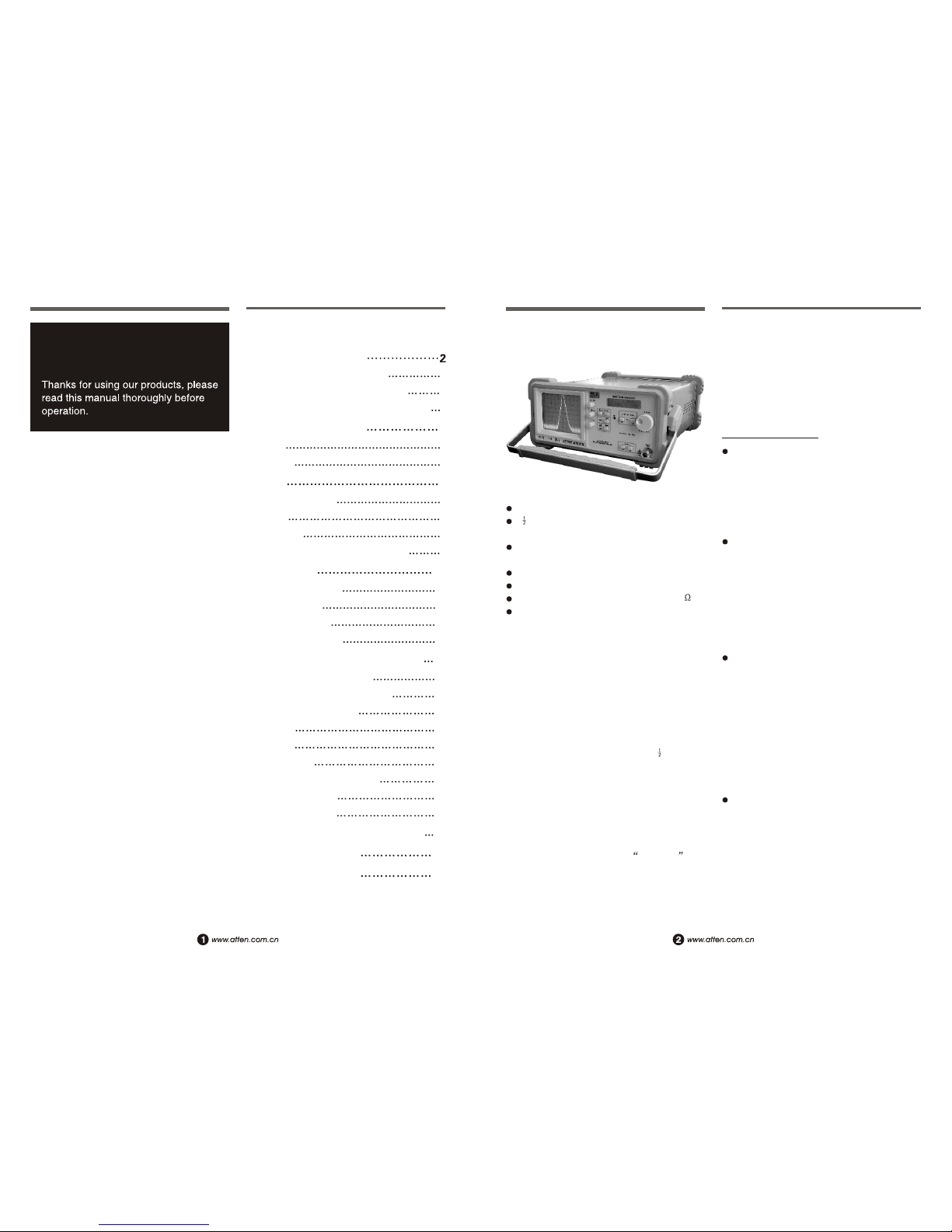
Spectrum Analyzer
AT6010/6011
AT6010
AT6010/AT6011
SPECTRUM ANALYZERS
for RF leakage/radiation detection, CATV/
MATV system troubleshooting, cellular
telephone/pocket pager test, and EMC
diagnostics. There is an optional measurement
output for a PC which makes documentation
of results easy and affordable with the AO500
Interface.
Applications
AT spectrum analyzer can carry out good
inspection to the faults of cable system and
wireless system including remote control,
cordless phone, cable TV and
communication equipment, as well as good
comparison and analysis to frequency of
signals.
AT6010 spectrum analyzer can test mobile
phone, RF circuits, for example, control
signal of logic circuit, base band signal.
local oscillator signal of RF circuit, IF signal
and transmission signal, It is very quick and
accurate to use AT6010 spectrum analyzer
to overhaul the fault of mobile phone which
can not enter the network, and determine the
fault point.
Electromagnetic Compatible (EMC) Testing:
measure the function of harmful
electromagnetic wave to be transmitted by
various electronic equipments. In addition,
it can output AM/FM demodulation signal
from socket PHONE, identify the broadcast
signal affected by noise. From authorization
aspect, it is very effective measurement
function for the evaluation and research in
advance to carry out the measurement of
radioactive noise.
Widely used for production, dev elopement,
education and scientific research. The form
of signal (such as RF pulse signal) can be
observed from ATTEN spectrum analyzer
clearly, where figures are expanded by
Fourier series, good for apprehend in
education and research.
Frequency Range: 0.15MHz to 1050MHz
5 % Digit LCD Display
(Center Frequency, 0.01MHz resolution)
-100 to +13dBm Amplitude Range, IF
RBW: 20kHz, 400kHz and Video-Filter
Tracking-Generator (AT6011 only)
Frequency range: 0.15MHz to 1050MHz
Output Voltage: +0dBm to 50dBm(50 )
Accessories: Users Manual, Power Cord
1pcs
Evolution of the original AT6010/AT6011 has
led to the new AT6010/6011 Spectrum
Analyzer/Tracking Generator which now
extends operation over 1GHz (frequency range
0.15 to 1050MHz). Both fine and coarse center
frequency controls, combined with a scan
width selector provide simple frequency
domain measurements from 1MHz/Div. To
1GHz/Div. Both models include a 5 digit
numeric LCD readout that can selectively
display either the center or marker frequency.
The AT6010/6011includes a tracking generator.
The AT6010/6011. The instruments are
suitable for per-compliance testing during
develop. Prior to third part testing. A near-field
sniffer probe set, AZ530, can be used to locate
cable and PC board emission hot spots and
evaluate EMC problems at the breadboard and
prototype level. The combination of AT6010/
6011 with the AZ530 is an excellent solution

Specifications
Frequency range: 0.15~1050MHz
Stability: 10ppm/year
Aging: 2ppm each year
Resolution of frequency display: 10kHz
(5 1/2 digit)
Readout accuracy: 2%* sweepwidth +5*
-3
10 *CF+10kHz
CF adjustment range: 0.15~1050MHz
Frequency synthesize: TCXO, DDS
Sweep width range: zero steps and 1-1000
MHz (1-2-5 steps)
Sweep width accuracy: 10%
Resolution bandwidth: 400kHz , 20kHz
Video-Filter bandwidth: 4kHz
Sweep time: 20ms
Amplitude specifications: 0.15~1050MHz
Range: -100dBm~+13dBm
Display: CRT, 8*10div
Display calibration: 10dB/div, logarithmic
Display range: 80dB (10dB/div)
Amplitude frequency response: 10dB
Attenuation, Zero Step, Resolution
Bandwidth 400kHz, Signal -17dBm:
4dB
LCD display: 2*16, Center frequency,
Sweep frequency width, Reference Level
Input attenuator: 0~40dB (4*10dB)
Accuracy (Input attenuation):
2dB/10dB
Reference level range: -27dBm~+13dBm
(each 10dB)
Accuracy: (Reference level) 500MHz (CF),
Zero step, RBW400kHz: 2dB
Average noise level: -90dBm
(RBW20kHz VBW4kHz)
Third order intermod.: at -27dBm two
signal 3MHz apart: -60dBc
nd
2 harmonic suppression: -27dBm, 0dB
attenuation, -50dBc
VSWR (Attenuation 10dB): typ. 1.5:1
Input/output
Signal input: N connector
Impedance: 50
Max. continuous RF input level:
10~40dB attenuation: +20dBm (0.1W)
0dB attenuation: +10dBm
Max. DC input voltage: 25V
DC output: DC power supply 6V FOR
DC
AZ530 Probe
Audio output: 3.5mmö, speaker connector
Turning knob control: Center frequency
Tracking generator (AT6011 only)
Signal out put: N connector
Impedance: 50
Frequency range: 0.15~1050MHz
Output level range: -50dBm to +1dBm
Frequency response: 2dB
Output attenuator: 0 to 40dB (4*10dB)
Output attenuator accuracy: 2dB
Radio frequency interference (RFI):
20dBc
Others
Operation temperature: +10 ~+40
Storage temperature: -40 ~+70
Line Voltage range: 220VAC 10%, 50Hz
~60Hz
Size (W*H*D): 285*125*380mm
Weight: AT6010 about 8.0kgs
AT6011 about 8.5kgs
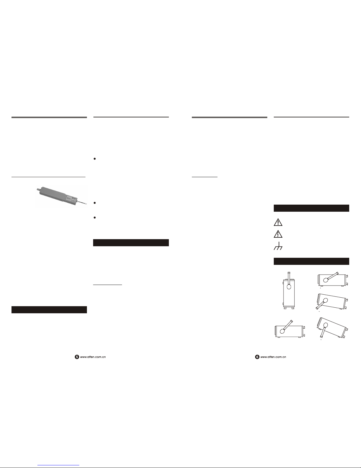
Near Field Sniffer Probes AZ530 (Optional)
Near Field Sniffer Probes AZ530 The AZ530
is the ideal toolkit for the investigation of RF
electromagnetic fields. Lt is indispensable of
EMI pre-compliance testing during product
development, prior to third party testing. The
set includes 3 hand-held probes with a built-in
pre-amplifier covering the frequency range
from 100KHz to over 1000MHz.
The probes-ove magnetic field probe, one
electric field probe, and one high impedance
Probe are all matched to the 50 inputs of
Spectrum analyzers or RF-receivers. The
power can be supplied either from batteries,
Ni-Cads or through a power cord directly
connected to an AT6010/AT6011 series
spectrum analyzer.
Signal feed via a 1.5m BNC-cable. When used
in connection with a spectrum analyzer or
measuring receiver, the probes cable used to
locate and qualify EMI sources, as well as
evaluate EMC problems at the breadboard and
prototype level. They enable the user to
evaluate radiated fields and perform shield
effectiveness comparisons. Mechanical
screening performance and immunity tests on
cables and components are easily performed.
Frequency range: 0.1~1000MHz
(lower frequency limit depends on type)
Output impedance: 50
Output connector: BNC-jack
Input capacitance: 2Pf
(high impedance probe)
Max. In put level: +10dBm
(without destruction)
DC-input voltage: 20V max
Supply Voltage: 6VDC
4AA size batteries
Supply-power of Analyzer
Supply Current: 8mA (M-Field Probe)
5mA (E-Field probe)
24mA (High imp probe)
Probe Dimensions (W*D*L):
40*19*195mm
Housing: Plastic
(electrically shielded internally)
Package contents: Carrying case
1 H-Field Probe
1 E-Field Probe
1 High Impedance Probe
1 BNC cable (1.5m)
1 Power Supply Cable
(Batteries or Ni-Cads are not included)
Specifications
The H-Field Near-Field probe
The H-Field probe provides a voltage to the
connected measurement system which is
proportional to
the magnetic radio
frequency (RF) field
strength existing at the
probe location, With this
probe, circuit therefore sources may be
localized in close proximity of each other. The
H-Field will decrease as the cube of the
distance from the source, A doubling of the
distance will reduce the H-field by a factor of
3
eight (H=1/d ). where d is the distance.
In the actual use of the H-field sensor one
observes therefore a rapid increase of the
probe's output voltage as the interference
source is approached. While investigating a
circuit board, the sources are immediately
obvious. It is easily noticed which component
(i.e.IC) causes interference and which does not.
in addition. by use of a spectrum analyzer the
maximum amplitude as a function of
frequency is easily identified. Therefore, one
can eliminate early in the development
components which are not suitable for EMC
purposes. The effectiveness of
countermeasures can be judged easily. One can
investigate shields for eaking areas and
cables or wires for conducted interference.
AZ530-M
The High-Impedance probe
The high-impedance probe (Hi-Z) permits the
determination
of the radio
frequency
interference (RFI) on
individual contacts or
printed circuit traces. It is a direct-contact
probe. The probe is of very high impedance
(near the insulation resistance of the printed
circuit material) and is loading the test point
with only 2pF (80 at 1GHz). Thereby one
AZ530-H
AZ530-E
can measure directly in a circuit without
significantly influencing the relationships in
the circuit with the probe. One can, for
example, measure the quantitative
effectiveness of filters or other or other
blocking measures. Individual pins of ICs can
be identified. With this Hi-Z probe individual
test points of a circuit can be connected to the
50W impedance of spectrum analyzer.
The E-field monopole probe has the highest
sensitivity
of the three
probes. It is
sensitive enough
to be used as an
antenna for radio or TV reception. With this
probe the entire radiation from a circuit or an
equipment can be measured.
It is used, for example, for example, to
determine the effectiveness of shielding
measures. With this probe, the entire
effectiveness of filters can be measured by
measuring the RFI which is conducted along
cables that leave the equipment and may
influence the total radiation.
In addition, the E-field probe may be used to
perform relative measurements for
certification tests. This makes it possible to
apply remedial suppression measures so that
any re-qualification results will be positive. In
addition, pre-testing for certification tests may
be performed so that no surprises are
encountered during the certification tests.
The E-Field Monopole Probe
Frequency Expander AT5000F Series (Optional)
Since the prices of 3GHz spectrum analyzers
are all above several ten thousands RMB, it is
not affordable for most radio fans, service men
and even medium or small sized enterprises.
Meantime, there are many signals above 1000
MHz in communication field, such as LO
(local oscillator) signals of mobile phone
usually between 1GHz to 2GHz, some are
exceed 2GHz, and 1800MHz, 2400MHz or
more. Based on above situations, favorable
frequency expanders have been developed
by Shenzhen ATTEN Electronics Co., Ltd.
AT5000F1 operating accompany with
AT6010 series spectrum analyzer of 1000
MHz, frequency can be expanded to 1050
Mhz to 2050MHz. Example: connect
AT5000F1 to AT6010 spectrum analyzer, if
a 800MHz signal display in spectrum
analyzer, then the tested signal should be
added 100MHz, so the frequency of tested
signal must be 1800MHz.
Frequency of AT5000F2 can be expanded to
2050MHz to 3050MHz, the tested frequency
is the display frequency add 2000MHz.
Frequency of AT5000F3 can be expanded to
3050MHz to 4050MHz, the tested frequency
is the display frequency add 3000MHz.
AT808 GSM Servicing RF Signal Generator (Optional)
AT808 Mobile Phone Signal Generator analogs
therefore signals of receiving frequency range
for mobile phones. The unit is mainly used in
maintaining failures of mobile receiver, it is
regarded as the spectrum analyzers best partner.
Since the phone's receiving signals transmit by
base station are instability, normally between
-70dBm to 90dBm, and maybe weaker in some
place or even no signal. In order to make it
easier to test and analyze the RF circuit (esp.
the IF signal) with spectrum analyzer, AT808
RF Signal Generator for mobile phones has
been researched by ATTEN, its frequency as
well as the output amplitude can be
quantitatively adjusted. Therefore, receiving or
no receiving problems can be examined by
Functions
using accompany with AT6010 spectrum
analyzer.
AT808 RF Signal Generator combines with
spectrum analyzer is very conveniently to
repair the receiver parts of mobile phone, if
you have some knowledge with the phone's
circuit, all failures of mobile phone can be
soon repaired by both RF signal generator and
spectrum analyzer.
Features
Output adjustable RF signal between 935MHz
to 960MHz, it can be set 3 fixed frequency
output by using the buttons. They are 945MHz
of Channel 50, 950MHz of Channel 75, 955
MHz of Channel 100. AT808 apply advanced
imported SMD to insure its high quality and
high reliability.
The signal amplitude range of the RF Signal
Generator is between -75 to -10dBm, it can be
set different amplitude of signal output by
pressing the attenuation buttons. In testing
phones without signal receiving, usually set
the output of signal generator to about -20dBm
(do not press down any attenuation button,
and the output amplitude of the unit is -20dBm).
In test the phones weak in receiving, usually
set the output of signal generator to about -70
dBm ( press three attenuation buttons: 20dB,
20dB and 10dB, and the output amplitude of
the unit is -70dBm ).
For Motorola and Nokia, can be set in the
testing status, set the signal of receiver to
Channel 75 (950MHz), select the Channel 75
of the unit. That is to make the phone's
operating channel matches with the channel
of AT808 generator, so that the signal of the
generator can enter into the phone.
For other phones, the RF signal can be set in
any channel, and required to use with spectrum
analyzer.
When connect mobile phone to RF signal
generator, just need to connect to the phone's
antenna tip via RF cable.
General Information
20
E
10
0
D
C
A
B
The AT6010/6011 spectrum analyzers are
easy to operate.The logical arrangement of the
controls allows anyone to quickly become
familiar with the operation of the instrument,
however, experienced users are also advised to
read through these instructions so that all
functions are understood.
Immediately after unpacking, the instrument
should be checked for mechanical damage and
loose parts in the interior. lf there is transport
damage, the supplier must be informed
immediately. The instrument must then not be
put into operation.
ATTENTION - refer to manual
Danger-High voltage
Protective ground (earth) terminal
Symbols
Tilt handle
 Loading...