

AT&T U-verse VIP2200, U-verse VIP2250 Installation Manual

AT&T U-verse Receiver
Installation Manual
Supports Models VIP2200 and VIP2250

Page intentionally Blank
CAUTION
RISK OF ELECTRIC SHOCK
DO NOT OPEN
CAUTION
RISK OF ELECTRIC SHOCK
DO NOT OPEN
TO REDUCE RISK OF ELECTRIC SHOCK, DO NOT
REMOVE COVER (OR BACK). NO USER-SERVICEABLE
PARTS INSIDE. REFER SERVICING TO QUALIFIED
SERVICE PERSONNEL.
Graphical symbols and supplemental warning markings are located on the back and bottom
of the terminal.
WARNING
TO REDUCE THE RISK OF FIRE OR SHOCK, DO NOT EXPOSE THIS APPLIANCE TO RAIN
OR MOISTURE.
The lightning flash with arrowhead symbol within an equilateral triangle
is intended to alert the user to the presence of uninsulated dangerous
voltage within the product’s enclosure that may be of sufficient
magnitude to constitute a risk of electric shock to persons.
The exclamation point within an equilateral triangle is intended to alert
the user to the presence of important operating and maintenance
(servicing) instructions in the literature accompanying the appliance.
Product identification and supply rating are provided on the label found
on the bottom of the unit.
IMPORTANT SAFETY INSTRUCTIONS
• Read these instructions.
• Keep these instructions.
• Heed all warnings.
• Follow all instructions.
• Do not use this apparatus near water.
• Clean only with a dry cloth.
• Do not block any ventilation openings. Install according to the manufacturer’s
instructions.
• Do not install near any heat sources, such as radiators, heat registers, stoves, or other
apparatus (including amplifiers) that produce heat.
• Do not defeat the safety purpose of the polarized or grounding type plug. A polarized
plug has two blades with one wider than the other. A grounding type plug has two
blades, and a third grounding prong. The wide blade or the third prong is provided for
your safety. If the provided plug does not fit into your outlet, consult an electrician for
replacement of the obsolete outlet.
• Protect the power cord from being walked on or pinched, particularly at plugs,
convenience receptacles, and the point where they exit from the apparatus.
• Only use attachments/accessories specified by the manufacturer.
• Unplug this apparatus during lightning storms or when unused for long periods of
time.
• Refer all servicing to qualified service personnel. Servicing is required when the
apparatus has been damaged in any way, such as the power supply cord or plug
is damaged, liquid has been spilled or objects have fallen into the apparatus, the
apparatus has been exposed to rain or moisture, does not operate normally, or has
been dropped.
VIP2200 Series High-Definition U-verse Receiver Installation Manual iii
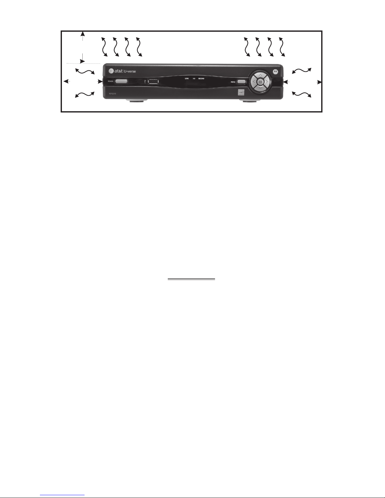
VENTILATE
At least
2 inches
2 inches
2 inches
Follow these important safety guidelines when positioning and connecting your TV
receiver:
• Do not block the slots and openings
• Do not place anything on top of the TV receiver
• Do not position the TV receiver in a confined space, such as an enclosed cabinet, that
does not provide adequate ventilation.
• Do not position the TV receiver near any external heat source that could raise the
temperature around the unit. Do not place the terminal on top of another heat
producing electronic device.
• Allow for adequate ventilation around the TV receiver to maintain normal operating
temperature. Do not place it in a sealed enclosure without providing for adequate
airflow.
• Do not plug the AC power cord into a switched power outlet.
• A coaxial cable screen shield needs to be connected to the earth at the building
entrance per ANSI/NFPA 70, the National Electrical Code (NEC), in particular Section
820.93, Grounding of Outer Conductive Shield of a Coaxial Cable.
IMPORTANT
Care and Handling of IPTV Receiver Units Equipped with a Hard Drive
A receiver containing an internal hard drive requires careful handling to avoid damaging the
drive. Be sure to follow these guidelines.
• If the receiver contains a hard drive (such as the VIP2250), it must be positioned so
that it remains horizontal and rests on its rubber feet. Do not attempt to mount or
position it in a vertical position.
• To allow the disk drive to spin down properly, wait at least 10 seconds after
disconnecting power before moving the receiver.
• Always transport the receiver in its original factory carton, or in an equally well-padded
container.
• Whether installed or being transported, do not expose the receiver to temperature
extremes. Do not exceed the range 41° F (5° C) to 122° F (50° C).
iv VIP2200 Series High-Definition U-verse Receiver Installation Manual
This manual includes the manufacturer’s recommended safeguards and all the information
needed to connect your receiver to both your in-home IP network and your entertainment
system. The safety and installation information was developed and provided primarily by
the receiver manufacturer, Motorola Mobility, Inc.

Contents
VIP2200 Series High-Definition U-verse Receiver Installation Manual v
Introduction ..............................................1
Overview ................................................2
Front Panel ...............................................2
VIP2200 and VIP2250 Rear Panel ..............................3
Connecting Your TV Receiver .................................4
Connection Options ........................................4
Connecting Your TV Receiver .................................5
Common Cabling Examples ..................................5
Connecting to an HDTV – Video Only ...........................6
Connecting to an HDTV – Audio Only...........................7
Connecting to a Home Theater Receiver ........................8
Connecting to a Stereo TV ...................................9
Connecting to a Stereo TV and Stereo VCR .....................10
Connecting to a Home Theater Receiver, TV, and VCR .............11
Troubleshooting ..........................................12

vi VIP2200 Series High-Definition U-verse Receiver Installation Manual

Introduction
Congratulations on receiving an ENERGY STAR® qualified Motorola® VIP2200 Series High
Definition U-verse TV Receiver.
The VIP2200 Series provides these extraordinary home entertainment features:
• High Definition TV (HDTV), which provides up to twice the color resolution and up to
six times the sharpness of standard TV when connected to an HD-capable TV
• On the VIP2250, a digital video recorder (DVR), which can record Standard Definition
and High Definition programs
• A direct digital connection to consumer audio and video devices through multiple
interfaces
• Video on Demand (VoD)
• Commercial free, CD quality music
This installation manual introduces the basic features, outlines important safeguards, and
provides options for integrating your TV receiver into your entertainment system. Take a
few moments to read through this manual. Its configuration diagrams and troubleshooting
section will help you make the most of your home entertainment experience.
Included in the carton:
• VIP2200 High-Definition (HD) and Standard-Definition (SD) receiver
OR
• VIP2250 High-Definition and Standard-Definition receiver with Digital Video Recorder
(DVR)
• Remote Control with batteries
• Power adapter and power cord
For more information about your U-verse TV service, refer to the other documentation from
your service provider.
In this manual, “VIP2200” refers to all VIP2200 Series TV receivers.
Dimensions:
VIP2200 and VIP2250 -- 10.0” W. x 8.0” D., x 2.2” H.
Unit Weight:
VIP2200 –– 2.91 lbs.
VIP2250 –– 4.37 lbs.
Top Assembly Weight (incl. carton and all inserts):
VIP2200 –– 4.98 lbs.
VIP2250 –– 6.39 lbs.
VIP2200 Series High-Definition U-verse Receiver Installation Manual 1

Overview
Front Panel
All VIP2200 Series models have identical front panel controls and lights. The illustration
below and the table following it describe the front-panel features.
Key Item Function
1 POWER Turns the U-verse TV receiver on or off
If held for ten (10) seconds or longer, restarts the TV receiver
Lights green when the TV receiver is on
2 USB USB 2.0 connector
3 LINK Lights green when receiving a video stream
4 HD Lights blue when receiving video resolution of 720p or 1080i
5 RECORD Lights red when a recording is in progress
6 MENU Displays the menu
7 Up/Down
arrow keys
Left/Right
arrow keys
OK
center key
Changes the channel (channel up/channel down)
Use to navigate through on-screen program guide and menu
Use to select programs or menu options
12
3
4
5
6
7
2 VIP2200 Series High-Definition U-verse Receiver Installation Manual
 Loading...