

Page 1
Quick start guide
TR1909
Trimline® telephone
with caller ID/call waiting
Page 2
1
Getting started
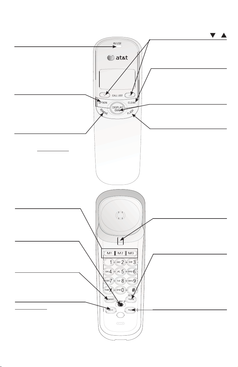
Handset layout
MEMORY
Press to access phone
numbers stored in the
memory.
Listening volume
Adjust the handset listening
volume to LO, MED, or HI.
PAUSE/REDIAL
When the handset is lifted, press
to redial the last number dialed.
When storing a number in the
memory or directory, press to
insert a 3-second pause in the
dialing sequence.
PROG
Press to store a phone number in
the memory.
M1, M2, M3
Press to dial a one-touch
number from the memory.
MUTE
Press and hold MUTE to silence
the microphone to prevent the
other party from hearing you,
but you will still be able to hear
the other party. Release MUTE
to return to the original twoway conversation.
Switch hook
When held, the telephone is in
idle mode.
When released, the telephone is
ready to make a call.
OPTION
Press to display the setting
options.
While in the option menu, press
to save the selection and move
to the next feature.
FLASH
When there is a call waiting signal,
press FLASH to put the current
call on hold and connect to the
new call. Press FLASH again to
return to the original call. Also,
press FLASH to activate other
telephone company subscriber
services such as three-way calling.
IN USE
Flashes quickly when there is an
incoming call.
Flashes slowly when the
telephone line cord is not
plugged into a wall jack or
another telephone at the same
line is in use.
CALL LIST /
When the telephone is in idle
mode, press to display caller ID
information.
REMOVE
While viewing the call log,
press to delete entry currently
displayed, press and hold to
remove all entries.
CLEAR
Press to exit dialing, to exit storing
a number in memory, to exit the
call log, or to return to the idle
screen anytime without saving the
changes.
DISPLAY DIAL
Press to dial the number currently
displayed.
Page 3
Getting started
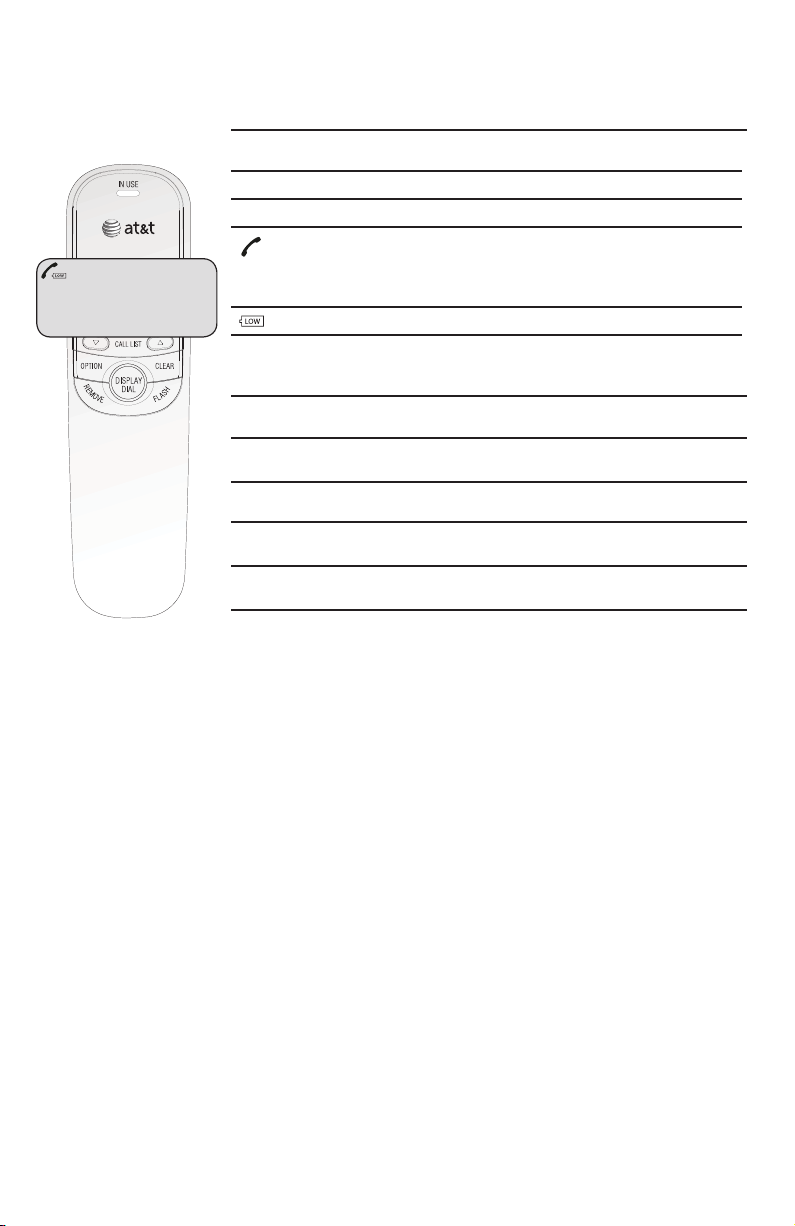
Screen display messages
CALL# Call number in the call log.
NEW New (unreviewed) call.
REP Repeat call from the same number.
The telephone line cord is not plugged into a wall jack.
The telephone or another telephone on the same line
is in use.
•
•
The battery power is low.
Screen icons
Screen display messages
REMOVE ALL? Remove all call log entries.
END OF LIST
You have reached the end of the call log
entries.
Pro Program a one-touch or two-touch memor y.
LIFT RECEIVER
A caller ID entry is ready to be dialed by
lifting the handset.
TOTAL XX NEW XX
The total and new (unreviewed) calls in the
call log.
CALL#
NEW
REP
0110 : 03AM 12/01
800-222-3111
TOTAL 12 NEW 01
2
Page 4

Getting started
Battery installation
Before using the telephone, you should install four good AA alkaline batteries
(not included) to provide memory backup and enable the use of some features.
The four AA batteries are required for caller ID features and the IN USE light to
work. If good batteries are not installed, the display only works when you lift
the handset.
If you unplug the telephone from the wall jack, or you lose telephone service
for over 10 minutes, and good batteries are not installed, the following
information is lost: call list, numbers stored in one- and two-touch memory,
redial list, and all settings in the feature menu. It is recommended that you
initially install new batteries and change the batteries soon after the low
battery icon appears.
Press on the tab to open the cover of the battery compartment.
1.
Install four new AA batteries (not included) in the battery compartment
2.
according to the label + and - engraved in the compartment.
Close the battery compartment cover. Make sure it clicks into place.
3.
Step 1
Press this
tab to
open.
NOTES:
Do not mix old and new batteries and do not mix alkaline and standard
•
(carbon-zinc) batteries.
When the batteries are installed, the screen will show 12:00 and the clock
•
will begin to run. It will reset to the correct time when the first caller ID
data is received.
Always disconnect all telephone lines from the wall outlets before replacing
•
batteries.
Install new batteries every six months to maintain the call log and
•
telephone memory.
Step 2
32
Step 3
Page 5

Getting started
4
Telephone installation
If you subscribe to high-speed Internet service (digital subscriber line - DSL)
through your telephone lines, you must install a DSL filter between the
telephone line cord and the telephone wall jack. The filter prevents noise and
caller ID problems caused by DSL interference. Please contact your DSL service
provider for more information about DSL filters. Install the telephone as shown
below.
Plug one end of the coiled
handset cord into the handset
jack on the left side of the
telephone base. Plug the other
end into the handset.
One end of the telephone line
cord has been plugged into the
telephone jack on the bottom
of the telephone base. Double
check that it is plugged in firmly.
Thread the cord through the
channel and out of the mounting
area as shown.
Plug the other end of the
telephone line cord into a
telephone wall jack.
Put the handset on the
telephone base.
1.
2.
3.
4.
5.
DSL filter
(not included)
Page 6

Getting started
Installation options
Wall installation
To install the telephone base in the wall mount position, make sure that you
first unplug all cords connected to the telephone base.
Lift the handset and place it aside. On the telephone base, pull out the
handset tab and rotate it 180 degrees. Replace the handset tab back to the
grooves until it clicks into position.
1.
Your telephone base is ready for tabletop use. If you want to mount your
telephone on a wall, use the provided wall mount bracket to connect with
a standard dual-stud telephone wall mounting plate. If you do not have this
mounting plate, you can purchase one from many hardware or consumer
electronic retailers. You might need a professional to install the mounting
plate.
3. Rotate the bracket to the wall
installation position, push the
bracket upwards as shown below
until it clicks into place.
5
2. Remove the bracket from the
base, hold the telephone base
with both hands, slide the
bracket upwards as the arrows
indicate.
Page 7

Getting started
6
4. Route the telephone line cord through
the slot as shown below and plug the
other end of the telephone line cord
into a telephone wall jack. To mount
the telephone on the wall, position
the mounting holes A and B over
the telephone outlet mounting studs.
Slide the bracket down firmly so the
telephone is held securely on the
telephone outlet mounting studs.
5. Place the handset back on the
telephone base.
Installation options
Tabletop installation
To return the bracket from the wall installation to tabletop use, follow the
instructions below.
2.
Lift the handset and place it aside. On the telephone base, pull out the
handset tab and rotate it 180 degrees. Replace the handset tab back to the
grooves until it clicks into position.
1. Remove the telephone base from the wall mounting plate. Unplug the
telephone line cord from the telephone wall jack and remove the cord from
the slots under the telephone base.
DSL filter
(not included)
A
B
Page 8

7
Getting started
Installation options
3. Remove the bracket from the base,
hold the telephone base firmly,
slide the bracket downwards as the
arrows indicate.
4. Rotate the bracket to the tabletop
installation position, push the
bracket down as shown below
until it clicks into place.
5. Route the telephone line cord through
the slot as shown below. Plug the
other end of the telephone line cord
into the telephone wall jack.
6. Place the handset back on
the telephone base.
Page 9

www.telephones.att.com
© 2009 Advanced American Telephones. All rights reserved.
AT&T and the AT&T logo are trademarks of AT&T Intellectual Property II, L.P. d/b/a
AT&T Intellectual Property licensed to Advanced American Telephones, San Antonio, TX 78219.
Trimline® is a registered trademark of Advanced American Telephones.
Printed in China. Issue 4 AT&T 3/09
 Loading...