

Page 1
DEFINITY Communications System
and System 75 and System 85
Terminals and Adjuncts
Reference Manual
AT&T 555-015-201
Issue 7, November 1994
Page 2

aaaaaaaaaaaaaaaaaaaaaaaaaaaaaaaaaaaaaaaaaaaaaaaaaaaaaaaaaaaaaaaaaaaaaaaaaaaaaaaaaaaaaaa
1994 AT&T
All Rights Reserved
Printed in USA
Notice
While reasonable effort was made to ensure that the information in this document was complete and accurate at the time of printing, AT&T cannot assume responsibility for any errors.
Changes and/or corrections to the information contained in this document may be incorporated into future issues.
ORDERING INFORMATION
Call: AT&T GBCS Publications Fulfillment Center
1 800 457-1235
Outside U.S.: 1 317 361-5353
Write: AT&T GBCS Publications Fulfillment Center
P.O. Box 4100
Crawfordsville, IN 47933
Order: Document No. AT&T 555-015-201
Issue 7, November 1994
Published by
AT&T GBCS Documentation Development Group
AT&T Bell Laboratories
Middletown, NJ 07748-0076
Page 3
aaaaaaaaaaaaaaaaaaaaaaaaaaaaaaaaaaaaaaaaaaaaaaaaaaaaaaaaaaaaaaaaaaaaaaaaaaa
Contents
INTRODUCTION ……………………………………………………………………………………… 1-1
Purpose ………………………………………………………………………………………………… 1-1
Organization …………………………………………………………………………………………… 1-3
GENERAL INFORMATION ………………………………………………………………………… 2-1
Voice Terminals ……………………………………………………………………………………… 2-1
Facilities Common to All Voice Terminals…………………………………………………………… 2-4
Adjuncts ………………………………………………………………………………………………… 2-11
EXPOSED PORT PROTECTION ………………………………………………………………… 2-21
Requirements ………………………………………………………………………………………… 2-21
AVAILABILITY ………………………………………………………………………………………… 2-25
ADJUNCT POWER …………………………………………………………………………………… 2-31
Information on the Older Power Supplies …………………………………………………………… 2-33
The MSP-1 Power Supply …………………………………………………………………………… 2-35
ADMINISTRATION …………………………………………………………………………………… 2-39
Aliasing ………………………………………………………………………………………………… 2-39
Button and Feature Caveats ………………………………………………………………………… 2-49
VOICE TERMINAL FEATURES ………………………………………………………………… 3-1
7101A Voice Terminal ……………………………………………………………………………… 3-17
Applications …………………………………………………………………………………………… 3-17
Physical Description…………………………………………………………………………………… 3-17
Distance Limitations…………………………………………………………………………………… 3-19
Power Requirements …………………………………………………………………………………3-19
Power Failure Operation ……………………………………………………………………………… 3-19
FCC Registration ……………………………………………………………………………………… 3-19
Hearing Aid Compatible ……………………………………………………………………………… 3-20
i
Page 4

aaaaaaaaaaaaaaaaaaaaaaaaaaaaaaaaaaaaaaaaaaaaaaaaaaaaaaaaaaaaaaaaaaaaaaaaaaa
7101A Equipment Price Element Code (PECs) …………………………………………………… 3-21
Adjuncts ………………………………………………………………………………………………… 3-21
Additional Documents ………………………………………………………………………………… 3-21
7102A and 7102 Plus Voice Terminals ……………………………………………………… 3-25
Applications …………………………………………………………………………………………… 3-25
Physical Description…………………………………………………………………………………… 3-25
Distance Limitations…………………………………………………………………………………… 3-28
Power Requirements …………………………………………………………………………………3-28
Power Failure Operation ……………………………………………………………………………… 3-28
FCC Registration ……………………………………………………………………………………… 3-29
Hearing Aid Compatible ……………………………………………………………………………… 3-29
7102 Equipment Price Element Code (PECs) ……………………………………………………… 3-29
Adjuncts ………………………………………………………………………………………………… 3-29
Additional Documents ………………………………………………………………………………… 3-29
7103A Fixed Feature Voice Terminal ………………………………………………………… 3-33
Applications …………………………………………………………………………………………… 3-33
Physical Description…………………………………………………………………………………… 3-33
Distance Limitations…………………………………………………………………………………… 3-35
Power Requirements …………………………………………………………………………………3-35
Power Failure Operation ……………………………………………………………………………… 3-35
FCC Registration ……………………………………………………………………………………… 3-36
Hearing Aid Compatible ……………………………………………………………………………… 3-36
7103A (Fixed Feature) Equipment Price Element Code (PECs) ………………………………… 3-37
Adjuncts ………………………………………………………………………………………………… 3-37
Additional Documents ………………………………………………………………………………… 3-37
7103A Programmable Voice Terminal ……………………………………………………… 3-41
Applications …………………………………………………………………………………………… 3-41
Physical Description…………………………………………………………………………………… 3-41
Distance Limitations…………………………………………………………………………………… 3-43
Power Requirements …………………………………………………………………………………3-43
ii
Page 5

aaaaaaaaaaaaaaaaaaaaaaaaaaaaaaaaaaaaaaaaaaaaaaaaaaaaaaaaaaaaaaaaaaaaaaaaaaa
Power Failure Operation ……………………………………………………………………………… 3-44
FCC Registration ……………………………………………………………………………………… 3-44
Hearing Aid Compatible ……………………………………………………………………………… 3-45
7103A (Programmable) Equipment Price Element Code (PECs)………………………………… 3-45
Adjuncts ………………………………………………………………………………………………… 3-45
Additional Documents ………………………………………………………………………………… 3-45
7104A Voice Terminal ……………………………………………………………………………… 3-49
Applications …………………………………………………………………………………………… 3-49
Physical Description…………………………………………………………………………………… 3-49
Distance Limitations…………………………………………………………………………………… 3-52
Power Requirements …………………………………………………………………………………3-52
Power Failure Operation ……………………………………………………………………………… 3-52
FCC Registration ……………………………………………………………………………………… 3-52
Hearing Aid Compatible ……………………………………………………………………………… 3-52
7104 Equipment Price Element Code (PECs) ……………………………………………………… 3-53
Adjuncts ………………………………………………………………………………………………… 3-53
Additional Documents ………………………………………………………………………………… 3-53
7203H Voice Terminal ……………………………………………………………………………… 3-57
Applications …………………………………………………………………………………………… 3-57
Physical Description…………………………………………………………………………………… 3-57
Distance Limitations…………………………………………………………………………………… 3-59
Power Requirements …………………………………………………………………………………3-59
Power Failure Operation ……………………………………………………………………………… 3-59
FCC Registration ……………………………………………………………………………………… 3-60
Hearing Aid Compatible ……………………………………………………………………………… 3-60
7203H Equipment Price Element Code (PECs) …………………………………………………… 3-61
Adjuncts ………………………………………………………………………………………………… 3-61
Additional Documents ………………………………………………………………………………… 3-61
7205H Voice Terminal ……………………………………………………………………………… 3-65
Applications …………………………………………………………………………………………… 3-65
iii
Page 6

aaaaaaaaaaaaaaaaaaaaaaaaaaaaaaaaaaaaaaaaaaaaaaaaaaaaaaaaaaaaaaaaaaaaaaaaaaa
Physical Description…………………………………………………………………………………… 3-65
Distance Limitations…………………………………………………………………………………… 3-67
Power Requirements …………………………………………………………………………………3-67
Power Failure Operation ……………………………………………………………………………… 3-68
FCC Registration ……………………………………………………………………………………… 3-68
Hearing Aid Compatible ……………………………………………………………………………… 3-68
7205H Equipment Price Element Code (PECs) …………………………………………………… 3-68
Adjuncts ………………………………………………………………………………………………… 3-68
Additional Documents ………………………………………………………………………………… 3-69
7303S Voice Terminal ……………………………………………………………………………… 3-73
Applications …………………………………………………………………………………………… 3-73
Physical Description…………………………………………………………………………………… 3-73
Distance Limitations…………………………………………………………………………………… 3-75
Power Requirements …………………………………………………………………………………3-76
Power Failure Operation ……………………………………………………………………………… 3-76
FCC Registration ……………………………………………………………………………………… 3-76
Hearing Aid Compatible ……………………………………………………………………………… 3-76
7303S Equipment Price Element Code (PECs) …………………………………………………… 3-76
Adjuncts ………………………………………………………………………………………………… 3-77
Additional Documents ………………………………………………………………………………… 3-77
7305S Voice Terminal ……………………………………………………………………………… 3-81
Applications …………………………………………………………………………………………… 3-81
Physical Description…………………………………………………………………………………… 3-81
Distance Limitations…………………………………………………………………………………… 3-83
Power Requirements …………………………………………………………………………………3-84
Power Failure Operation ……………………………………………………………………………… 3-84
FCC Registration ……………………………………………………………………………………… 3-84
Hearing Aid Compatible ……………………………………………………………………………… 3-85
7305S Equipment Price Element Code (PECs) …………………………………………………… 3-85
Adjuncts ………………………………………………………………………………………………… 3-85
iv
Page 7

aaaaaaaaaaaaaaaaaaaaaaaaaaaaaaaaaaaaaaaaaaaaaaaaaaaaaaaaaaaaaaaaaaaaaaaaaaa
Additional Documents ………………………………………………………………………………… 3-86
7401D and 7401 Plus Voice Terminals ……………………………………………………… 3-91
Applications …………………………………………………………………………………………… 3-91
Special Operational Characteristics ………………………………………………………………… 3-91
Physical Features……………………………………………………………………………………… 3-92
Distance Limitations…………………………………………………………………………………… 3-94
Power Requirements …………………………………………………………………………………3-95
Switch Administration ………………………………………………………………………………… 3-96
Power Failure Operation ……………………………………………………………………………… 3-100
FCC Registration ……………………………………………………………………………………… 3-100
UL and CSA Approval ………………………………………………………………………………… 3-100
Hearing Aid Compatible ……………………………………………………………………………… 3-100
7401D Equipment PECs & COMCODES …………………………………………………………… 3-100
7401 Plus Equipment with PECs and COMCODES ……………………………………………… 3-101
Adjuncts ………………………………………………………………………………………………… 3-103
Additional Documents ………………………………………………………………………………… 3-104
7402 Plus Voice Terminal ………………………………………………………………………… 3-107
Applications …………………………………………………………………………………………… 3-107
Physical Features……………………………………………………………………………………… 3-107
Distance Limitations…………………………………………………………………………………… 3-111
Power Requirements …………………………………………………………………………………3-111
Switch Administration ………………………………………………………………………………… 3-112
Power Failure Operation ……………………………………………………………………………… 3-115
FCC Registration ……………………………………………………………………………………… 3-115
UL and CSA Approval ………………………………………………………………………………… 3-115
Hearing Aid Compatible ……………………………………………………………………………… 3-115
7402 Plus Equipment PECs and COMCODES …………………………………………………… 3-115
Adjuncts ………………………………………………………………………………………………… 3-116
Additional Documents ………………………………………………………………………………… 3-117
v
Page 8

aaaaaaaaaaaaaaaaaaaaaaaaaaaaaaaaaaaaaaaaaaaaaaaaaaaaaaaaaaaaaaaaaaaaaaaaaaa
7403D Voice Terminal ……………………………………………………………………………… 3-121
Applications …………………………………………………………………………………………… 3-121
Physical Description…………………………………………………………………………………… 3-121
Distance Limitations…………………………………………………………………………………… 3-123
Power Requirements …………………………………………………………………………………3-123
Power Failure Operation ……………………………………………………………………………… 3-124
FCC Registration ……………………………………………………………………………………… 3-124
Hearing Aid Compatible ……………………………………………………………………………… 3-125
7403D Equipment Price Element Code (PECs) …………………………………………………… 3-125
Adjuncts ………………………………………………………………………………………………… 3-125
Additional Documents ………………………………………………………………………………… 3-125
7404D Voice Terminal ……………………………………………………………………………… 3-129
Applications …………………………………………………………………………………………… 3-129
Physical Description…………………………………………………………………………………… 3-129
Distance Limitations…………………………………………………………………………………… 3-131
Power Requirements …………………………………………………………………………………3-132
Power Failure Operation ……………………………………………………………………………… 3-132
FCC Registration ……………………………………………………………………………………… 3-132
Hearing Aid Compatible ……………………………………………………………………………… 3-132
7404D Equipment Price Element Code (PECs) …………………………………………………… 3-132
Adjuncts ………………………………………………………………………………………………… 3-133
Additional Documents ………………………………………………………………………………… 3-133
7405D Voice Terminal ……………………………………………………………………………… 3-137
Applications …………………………………………………………………………………………… 3-137
Physical Description…………………………………………………………………………………… 3-137
Distance Limitations…………………………………………………………………………………… 3-139
Power Requirements …………………………………………………………………………………3-140
Power Failure Operation ……………………………………………………………………………… 3-140
FCC Registration ……………………………………………………………………………………… 3-140
Hearing Aid Compatible ……………………………………………………………………………… 3-140
vi
Page 9

aaaaaaaaaaaaaaaaaaaaaaaaaaaaaaaaaaaaaaaaaaaaaaaaaaaaaaaaaaaaaaaaaaaaaaaaaaa
7405D Equipment Price Element Code (PECs) …………………………………………………… 3-141
Adjuncts ………………………………………………………………………………………………… 3-141
Additional Documents ………………………………………………………………………………… 3-142
7406D, 7406BIS, and 7406 Plus Voice Terminals ……………………………………… 3-147
Applications …………………………………………………………………………………………… 3-148
Physical Features……………………………………………………………………………………… 3-148
Distance Limitations…………………………………………………………………………………… 3-155
Power Requirements …………………………………………………………………………………3-155
Switch Administration ………………………………………………………………………………… 3-156
Power Failure Operation ……………………………………………………………………………… 3-162
FCC Registration ……………………………………………………………………………………… 3-162
UL and CSA Approval ………………………………………………………………………………… 3-162
Hearing Aid Compatibility …………………………………………………………………………… 3-162
7406D/7406BIS Equipment PECs & COMCODES………………………………………………… 3-162
7406 Plus Equipment PECs and COMCODES …………………………………………………… 3-165
Adjuncts ………………………………………………………………………………………………… 3-166
Additional Documents ………………………………………………………………………………… 3-166
7407D, Enhanced 7407D, and 7407 Plus Voice Terminals…………………………… 3-173
Applications …………………………………………………………………………………………… 3-174
Special Operational Characteristics ………………………………………………………………… 3-174
Physical Features……………………………………………………………………………………… 3-177
Distance Limitations…………………………………………………………………………………… 3-184
Power Requirements …………………………………………………………………………………3-184
Switch Administration ………………………………………………………………………………… 3-185
Power Failure Operation ……………………………………………………………………………… 3-192
FCC Registration ……………………………………………………………………………………… 3-192
UL and CSA Approval ………………………………………………………………………………… 3-192
Hearing Aid Compatible ……………………………………………………………………………… 3-192
7407D/Enhanced 7407D Equipment PECs & COMCODES ……………………………………… 3-192
7407 Plus Equipment PECs and COMCODES …………………………………………………… 3-193
vii
Page 10

aaaaaaaaaaaaaaaaaaaaaaaaaaaaaaaaaaaaaaaaaaaaaaaaaaaaaaaaaaaaaaaaaaaaaaaaaaa
Adjuncts ………………………………………………………………………………………………… 3-194
Additional Documents ………………………………………………………………………………… 3-195
7410D and 7410 Plus Voice Terminals ……………………………………………………… 3-199
Applications …………………………………………………………………………………………… 3-199
Physical Features……………………………………………………………………………………… 3-199
Distance Limitations…………………………………………………………………………………… 3-202
Power Requirements …………………………………………………………………………………3-203
Switch Administration ………………………………………………………………………………… 3-204
Power Failure Operation ……………………………………………………………………………… 3-209
FCC Registration ……………………………………………………………………………………… 3-209
UL and CSA Approval ………………………………………………………………………………… 3-209
Hearing Aid Compatible ……………………………………………………………………………… 3-209
7410D Equipment with PECs and COMCODES …………………………………………………… 3-209
7410 Plus Equipment PECs and COMCODES …………………………………………………… 3-210
Adjuncts ………………………………………………………………………………………………… 3-211
Additional Documents ………………………………………………………………………………… 3-212
7434D Voice Terminal ……………………………………………………………………………… 3-215
Applications …………………………………………………………………………………………… 3-215
Physical Description…………………………………………………………………………………… 3-215
Distance Limitations…………………………………………………………………………………… 3-218
Power Requirements …………………………………………………………………………………3-219
Power Failure Operation ……………………………………………………………………………… 3-219
FCC Registration ……………………………………………………………………………………… 3-219
Hearing Aid Compatible ……………………………………………………………………………… 3-219
7434 Equipment Price Element Codes (PECs) …………………………………………………… 3-219
Adjuncts ………………………………………………………………………………………………… 3-220
Additional Documents ………………………………………………………………………………… 3-220
7444 Voice Terminal ………………………………………………………………………………… 3-223
Applications …………………………………………………………………………………………… 3-223
Physical Description…………………………………………………………………………………… 3-223
viii
Page 11

aaaaaaaaaaaaaaaaaaaaaaaaaaaaaaaaaaaaaaaaaaaaaaaaaaaaaaaaaaaaaaaaaaaaaaaaaaa
Distance Limitations…………………………………………………………………………………… 3-227
Power Requirements …………………………………………………………………………………3-228
Switch Administration ………………………………………………………………………………… 3-229
Power Failure Operation ……………………………………………………………………………… 3-233
FCC Registration ……………………………………………………………………………………… 3-233
UL and CSA Approval ………………………………………………………………………………… 3-233
Hearing Aid Compatible ……………………………………………………………………………… 3-233
7444 Equipment PECs and COMCODES ………………………………………………………… 3-233
Adjuncts ………………………………………………………………………………………………… 3-234
Additional Documents ………………………………………………………………………………… 3-235
8403 Voice Terminal ………………………………………………………………………………… 3-239
Applications …………………………………………………………………………………………… 3-239
Physical Features……………………………………………………………………………………… 3-239
Wiring Information……………………………………………………………………………………… 3-243
Distance Limitations…………………………………………………………………………………… 3-245
Power Requirements …………………………………………………………………………………3-246
Switch Administration ………………………………………………………………………………… 3-246
Power Failure Operation ……………………………………………………………………………… 3-250
FCC Registration ……………………………………………………………………………………… 3-250
UL and CSA Approval ………………………………………………………………………………… 3-250
Hearing Aid Compatible ……………………………………………………………………………… 3-250
8403 Equipment PECs & COMCODES …………………………………………………………… 3-250
Adjuncts ………………………………………………………………………………………………… 3-251
Additional Documents ………………………………………………………………………………… 3-252
8410 Voice Terminal ………………………………………………………………………………… 3-255
Applications …………………………………………………………………………………………… 3-255
Physical Features……………………………………………………………………………………… 3-255
Wiring Information……………………………………………………………………………………… 3-263
Distance Limitations…………………………………………………………………………………… 3-265
Power Requirements …………………………………………………………………………………3-265
ix
Page 12

aaaaaaaaaaaaaaaaaaaaaaaaaaaaaaaaaaaaaaaaaaaaaaaaaaaaaaaaaaaaaaaaaaaaaaaaaaa
Switch Administration ………………………………………………………………………………… 3-266
Power Failure Operation ……………………………………………………………………………… 3-270
FCC Registration ……………………………………………………………………………………… 3-270
UL and CSA Approval ………………………………………………………………………………… 3-270
Hearing Aid Compatible ……………………………………………………………………………… 3-270
8410 Equipment PECs & COMCODES …………………………………………………………… 3-270
Adjuncts ………………………………………………………………………………………………… 3-272
Additional Documents ………………………………………………………………………………… 3-272
8434 and 8434DX Voice Terminal ……………………………………………………………… 3-277
Applications …………………………………………………………………………………………… 3-278
Physical Description…………………………………………………………………………………… 3-279
Wiring Information……………………………………………………………………………………… 3-286
Distance Limitations…………………………………………………………………………………… 3-287
Power Requirements …………………………………………………………………………………3-288
Switch Administration ………………………………………………………………………………… 3-289
Power Failure Operation ……………………………………………………………………………… 3-293
FCC Registration ……………………………………………………………………………………… 3-293
UL and CSA Approval ………………………………………………………………………………… 3-293
Hearing Aid Compatible ……………………………………………………………………………… 3-293
8434 and 8434DX Equipment PECs and COMCODES…………………………………………… 3-293
Adjuncts ………………………………………………………………………………………………… 3-295
Additional Documents ………………………………………………………………………………… 3-295
CALLMASTER and CALLMASTER II and III Voice Terminals ………………… 3-301
Applications …………………………………………………………………………………………… 3-302
Special Operational Characteristics ………………………………………………………………… 3-302
Physical Description…………………………………………………………………………………… 3-303
Distance Limitations…………………………………………………………………………………… 3-307
Power Requirements …………………………………………………………………………………3-307
Switch Administration ………………………………………………………………………………… 3-307
Power Failure Operation ……………………………………………………………………………… 3-312
x
Page 13

aaaaaaaaaaaaaaaaaaaaaaaaaaaaaaaaaaaaaaaaaaaaaaaaaaaaaaaaaaaaaaaaaaaaaaaaaaa
FCC Registration ……………………………………………………………………………………… 3-312
CALLMASTER Equipment Price Element Code (PECs) ………………………………………… 3-312
Adjuncts ………………………………………………………………………………………………… 3-313
Additional Documents ………………………………………………………………………………… 3-313
500 Series Telephone ……………………………………………………………………………… 3-317
Applications …………………………………………………………………………………………… 3-317
Physical Description…………………………………………………………………………………… 3-317
Distance Limitations…………………………………………………………………………………… 3-319
Power Requirements …………………………………………………………………………………3-319
Power Failure Operation ……………………………………………………………………………… 3-320
FCC Registration ……………………………………………………………………………………… 3-320
500 Series Equipment Price Element Code (PECs) ……………………………………………… 3-320
Adjuncts ………………………………………………………………………………………………… 3-320
Additional Documents ………………………………………………………………………………… 3-320
2500 Series Telephones …………………………………………………………………………… 3-323
Applications …………………………………………………………………………………………… 3-323
Physical Description…………………………………………………………………………………… 3-323
Distance Limitations…………………………………………………………………………………… 3-325
Power Requirements …………………………………………………………………………………3-325
Power Failure Operation ……………………………………………………………………………… 3-325
FCC Registration ……………………………………………………………………………………… 3-325
Price Element Code (PECs) ………………………………………………………………………… 3-326
Adjuncts ………………………………………………………………………………………………… 3-326
2500 DMGC Telephone……………………………………………………………………………… 3-329
Applications …………………………………………………………………………………………… 3-329
Physical Description…………………………………………………………………………………… 3-329
Distance Limitations…………………………………………………………………………………… 3-331
Power Requirements …………………………………………………………………………………3-331
Power Failure Operation ……………………………………………………………………………… 3-331
FCC Registration ……………………………………………………………………………………… 3-331
xi
Page 14

aaaaaaaaaaaaaaaaaaaaaaaaaaaaaaaaaaaaaaaaaaaaaaaaaaaaaaaaaaaaaaaaaaaaaaaaaaa
2500 DMGC Equipment Price Element Code (PECs) …………………………………………… 3-332
Adjuncts ………………………………………………………………………………………………… 3-332
Additional Documents ………………………………………………………………………………… 3-332
2500 YMGK Telephone……………………………………………………………………………… 3-335
Applications …………………………………………………………………………………………… 3-335
Physical Description…………………………………………………………………………………… 3-335
Distance Limitations…………………………………………………………………………………… 3-337
Power Requirements …………………………………………………………………………………3-337
Power Failure Operation ……………………………………………………………………………… 3-337
FCC Registration ……………………………………………………………………………………… 3-337
2500 YMGK Equipment Price Element Code (PECs)……………………………………………… 3-338
Adjuncts ………………………………………………………………………………………………… 3-338
Additional Documents ………………………………………………………………………………… 3-338
2500 MMGL and 2500 YMGL Telephones…………………………………………………… 3-341
Applications …………………………………………………………………………………………… 3-341
Physical Description…………………………………………………………………………………… 3-341
Distance Limitations…………………………………………………………………………………… 3-344
Power Requirements …………………………………………………………………………………3-344
Switch Administration ………………………………………………………………………………… 3-344
Power Failure Operation ……………………………………………………………………………… 3-344
FCC Registration ……………………………………………………………………………………… 3-345
UL and CSA Approval ………………………………………………………………………………… 3-345
Hearing Aid Compatible ……………………………………………………………………………… 3-345
2500 MMGL and 2500 YMGL Equipment Price Element Codes (PECs) ……………………… 3-345
8101 Telephone ……………………………………………………………………………………… 3-349
Applications …………………………………………………………………………………………… 3-349
Physical Description…………………………………………………………………………………… 3-349
Other Physical Features ……………………………………………………………………………… 3-350
Distance Limitations…………………………………………………………………………………… 3-352
Power Requirements …………………………………………………………………………………3-352
xii
Page 15

aaaaaaaaaaaaaaaaaaaaaaaaaaaaaaaaaaaaaaaaaaaaaaaaaaaaaaaaaaaaaaaaaaaaaaaaaaa
Switch Administration ………………………………………………………………………………… 3-352
Power Failure Operation ……………………………………………………………………………… 3-353
Ringer Equivalency Numbers …………………………………………………………………………3-353
FCC Registration ……………………………………………………………………………………… 3-353
Hearing Aid Compatible ……………………………………………………………………………… 3-353
8101 Telephone PECs and COMCODES…………………………………………………………… 3-353
Adjuncts ………………………………………………………………………………………………… 3-354
Additional Documents ………………………………………………………………………………… 3-354
8102 and 8102M Telephones …………………………………………………………………… 3-357
Applications …………………………………………………………………………………………… 3-357
Physical Description…………………………………………………………………………………… 3-357
Other Physical Features ……………………………………………………………………………… 3-359
Distance Limitations…………………………………………………………………………………… 3-360
Power Requirements …………………………………………………………………………………3-360
Switch Administration ………………………………………………………………………………… 3-361
Administration of Hidden Features…………………………………………………………………… 3-362
Power Failure Operation ……………………………………………………………………………… 3-362
Ringer Equivalency Numbers …………………………………………………………………………3-362
FCC Registration ……………………………………………………………………………………… 3-362
Hearing Aid Compatible ……………………………………………………………………………… 3-363
8102 and 8102M Telephones PECs and COMCODES …………………………………………… 3-363
Adjuncts ………………………………………………………………………………………………… 3-364
Additional Documents ………………………………………………………………………………… 3-365
8110 and 8110M Telephones …………………………………………………………………… 3-369
Applications …………………………………………………………………………………………… 3-369
Physical Description…………………………………………………………………………………… 3-369
Distance Limitations…………………………………………………………………………………… 3-373
Power Requirements …………………………………………………………………………………3-374
Switch Administration ………………………………………………………………………………… 3-375
Administration of Hidden Features…………………………………………………………………… 3-375
xiii
Page 16

aaaaaaaaaaaaaaaaaaaaaaaaaaaaaaaaaaaaaaaaaaaaaaaaaaaaaaaaaaaaaaaaaaaaaaaaaaa
Power Failure Operation ……………………………………………………………………………… 3-375
Ringer Equivalency Numbers …………………………………………………………………………3-375
FCC Registration ……………………………………………………………………………………… 3-376
Hearing Aid Compatible ……………………………………………………………………………… 3-376
8110 and 8110M Telephones Equipment PECs and COMCODES ……………………………… 3-376
Adjuncts ………………………………………………………………………………………………… 3-378
Additional Documents ………………………………………………………………………………… 3-378
ISDN 7505 Modular Terminal …………………………………………………………………… 3-381
Applications …………………………………………………………………………………………… 3-381
Physical Description…………………………………………………………………………………… 3-381
Distance Limitations…………………………………………………………………………………… 3-384
Power Requirements …………………………………………………………………………………3-384
Terminating Resistor ………………………………………………………………………………… 3-384
Power Failure Operation ……………………………………………………………………………… 3-384
FCC Registration ……………………………………………………………………………………… 3-384
Hearing Aid Compatible ……………………………………………………………………………… 3-385
7505 Equipment Price Element Code (PECs) ……………………………………………………… 3-385
Adjuncts ………………………………………………………………………………………………… 3-386
Additional Documents ………………………………………………………………………………… 3-386
ISDN 7506 Display Terminal……………………………………………………………………… 3-389
Applications …………………………………………………………………………………………… 3-389
Physical Description…………………………………………………………………………………… 3-389
Distance Limitations…………………………………………………………………………………… 3-393
Power Requirements …………………………………………………………………………………3-393
Terminating Resistor ………………………………………………………………………………… 3-393
Power Failure Operation ……………………………………………………………………………… 3-393
FCC Registration ……………………………………………………………………………………… 3-393
Hearing Aid Compatible ……………………………………………………………………………… 3-393
7506 Equipment Price Element Code (PECs) ……………………………………………………… 3-394
Adjuncts ………………………………………………………………………………………………… 3-394
xiv
Page 17

aaaaaaaaaaaaaaaaaaaaaaaaaaaaaaaaaaaaaaaaaaaaaaaaaaaaaaaaaaaaaaaaaaaaaaaaaaa
Additional Documents ………………………………………………………………………………… 3-394
ISDN 7507 Display Terminal……………………………………………………………………… 3-397
Applications …………………………………………………………………………………………… 3-397
Physical Description…………………………………………………………………………………… 3-397
Distance Limitations…………………………………………………………………………………… 3-400
Power Requirements …………………………………………………………………………………3-400
Terminating Resistor ………………………………………………………………………………… 3-401
Power Failure Operation ……………………………………………………………………………… 3-401
FCC Registration ……………………………………………………………………………………… 3-401
Hearing Aid Compatible ……………………………………………………………………………… 3-401
7507 Equipment Price Element Code (PECs) ……………………………………………………… 3-402
Adjuncts ………………………………………………………………………………………………… 3-402
Additional Documents ………………………………………………………………………………… 3-402
ISDN 8503T Voice Terminal ……………………………………………………………………… 3-405
Applications …………………………………………………………………………………………… 3-405
Physical Description…………………………………………………………………………………… 3-405
Other Physical Features ……………………………………………………………………………… 3-408
Distance Limitations…………………………………………………………………………………… 3-410
Power Requirements …………………………………………………………………………………3-410
Switch Administration ………………………………………………………………………………… 3-411
Power Failure Operation ……………………………………………………………………………… 3-411
FCC Registration ……………………………………………………………………………………… 3-411
Hearing Aid Compatible ……………………………………………………………………………… 3-411
8503T Equipment PECs and COMCODES ………………………………………………………… 3-412
Adjuncts ………………………………………………………………………………………………… 3-412
Additional Documents ………………………………………………………………………………… 3-413
ISDN 8510T Voice/Data Terminal ……………………………………………………………… 3-417
Applications …………………………………………………………………………………………… 3-417
Physical Description…………………………………………………………………………………… 3-417
Data Features ………………………………………………………………………………………… 3-424
xv
Page 18

aaaaaaaaaaaaaaaaaaaaaaaaaaaaaaaaaaaaaaaaaaaaaaaaaaaaaaaaaaaaaaaaaaaaaaaaaaa
Distance Limitations…………………………………………………………………………………… 3-424
Power Requirements …………………………………………………………………………………3-425
Switch Administration ………………………………………………………………………………… 3-427
Button Numbering………………………………………………………………………………………3-427
The Service Profiler ID (SPID) ……………………………………………………………………… 3-427
Hidden/Craft Features ………………………………………………………………………………… 3-428
Power Failure Operation ……………………………………………………………………………… 3-428
FCC Registration ……………………………………………………………………………………… 3-428
Hearing Aid Compatible ……………………………………………………………………………… 3-428
8510T Equipment PECs and COMCODES ………………………………………………………… 3-429
Adjuncts ………………………………………………………………………………………………… 3-430
Additional Documents ………………………………………………………………………………… 3-430
ISDN 8520T Voice/Data Terminal ……………………………………………………………… 3-433
Applications …………………………………………………………………………………………… 3-433
Physical Description…………………………………………………………………………………… 3-433
Data Features ………………………………………………………………………………………… 3-438
Distance Limitations…………………………………………………………………………………… 3-439
Power Requirements …………………………………………………………………………………3-439
Switch Administration ………………………………………………………………………………… 3-440
Button Numbering………………………………………………………………………………………3-440
The Service Profiler ID (SPID) ……………………………………………………………………… 3-440
Hidden/Craft Features ………………………………………………………………………………… 3-441
Power Failure Operation ……………………………………………………………………………… 3-441
FCC Registration ……………………………………………………………………………………… 3-441
Hearing Aid Compatible ……………………………………………………………………………… 3-441
8520T Equipment PECs and COMCODES ………………………………………………………… 3-441
Adjuncts ………………………………………………………………………………………………… 3-442
Additional Documents ………………………………………………………………………………… 3-443
ISDN 8528T Voice Terminal ……………………………………………………………………… 3-447
Applications …………………………………………………………………………………………… 3-447
xvi
Page 19

aaaaaaaaaaaaaaaaaaaaaaaaaaaaaaaaaaaaaaaaaaaaaaaaaaaaaaaaaaaaaaaaaaaaaaaaaaa
Physical Description…………………………………………………………………………………… 3-447
Distance Limitations…………………………………………………………………………………… 3-453
Power Requirements …………………………………………………………………………………3-453
Switch Administration ………………………………………………………………………………… 3-453
Button Numbering………………………………………………………………………………………3-453
The Service Profiler ID (SPID) ……………………………………………………………………… 3-454
Power Failure Operation ……………………………………………………………………………… 3-454
FCC Registration ……………………………………………………………………………………… 3-454
Hearing Aid Compatible ……………………………………………………………………………… 3-454
8528T Equipment PECs and COMCODES ………………………………………………………… 3-454
Adjuncts ………………………………………………………………………………………………… 3-455
Additional Documents ………………………………………………………………………………… 3-456
MDC 9000 Cordless Telephone ………………………………………………………………… 3-461
Applications …………………………………………………………………………………………… 3-461
Physical Features……………………………………………………………………………………… 3-461
Out-of-Range Indication ……………………………………………………………………………… 3-465
Distance and Installation Limitations (for the Charging Base) …………………………………… 3-465
Switch Administration ………………………………………………………………………………… 3-467
FCC Registration ……………………………………………………………………………………… 3-468
Hearing Aid Compatibility …………………………………………………………………………… 3-468
MDC 9000 Equipment PECs & COMCODES ……………………………………………………… 3-469
Additional Documents ………………………………………………………………………………… 3-470
MDW 9000 Wireless Telephone ………………………………………………………………… 3-475
Applications …………………………………………………………………………………………… 3-475
Physical Features……………………………………………………………………………………… 3-475
Out-of-Range Indication ……………………………………………………………………………… 3-480
Distance and Installation Limitations ………………………………………………………………… 3-481
Switch Administration ………………………………………………………………………………… 3-481
FCC Registration ……………………………………………………………………………………… 3-483
Hearing Aid Compatibility …………………………………………………………………………… 3-483
xvii
Page 20

aaaaaaaaaaaaaaaaaaaaaaaaaaaaaaaaaaaaaaaaaaaaaaaaaaaaaaaaaaaaaaaaaaaaaaaaaaa
UL and CSA Approval ………………………………………………………………………………… 3-483
MDW 9000 Equipment PECs & COMCODES ……………………………………………………… 3-484
Additional Documents ………………………………………………………………………………… 3-485
Other Voice Terminals……………………………………………………………………………… 3-487
Voice Terminals Reusable from Other Systems …………………………………………………… 3-487
Models 7302H, 7303H, 7305H01B, and 7305H02B ……………………………………………… 3-487
Multi-Button Electronic Telephone (MET) Sets …………………………………………………… 3-488
ADJUNCTS ……………………………………………………………………………………………… 4-1
Call Coverage Modules …………………………………………………………………………… 4-5
Applications …………………………………………………………………………………………… 4-5
Physical Description…………………………………………………………………………………… 4-5
Power …………………………………………………………………………………………………… 4-6
Call Coverage Module PEC Codes ………………………………………………………………… 4-6
Considerations …………………………………………………………………………………………4-6
Digital Display Module………………………………………………………………………………4-9
Applications …………………………………………………………………………………………… 4-9
Physical Description…………………………………………………………………………………… 4-9
Power …………………………………………………………………………………………………… 4-11
Digital Display Module PEC Codes ………………………………………………………………… 4-11
Considerations …………………………………………………………………………………………4-11
Function Key Modules………………………………………………………………………………4-15
Applications …………………………………………………………………………………………… 4-15
Physical Description…………………………………………………………………………………… 4-15
Power …………………………………………………………………………………………………… 4-15
Considerations …………………………………………………………………………………………4-16
Digital Terminal Data Module PEC Codes ………………………………………………………… 4-16
801A Expansion Module…………………………………………………………………………… 4-19
Applications …………………………………………………………………………………………… 4-19
xviii
Page 21

aaaaaaaaaaaaaaaaaaaaaaaaaaaaaaaaaaaaaaaaaaaaaaaaaaaaaaaaaaaaaaaaaaaaaaaaaaa
Physical Description…………………………………………………………………………………… 4-19
Power …………………………………………………………………………………………………… 4-20
Administering the Expansion Module ……………………………………………………………… 4-20
801A Expansion Module PEC Codes ……………………………………………………………… 4-21
Additional Documents ………………………………………………………………………………… 4-21
Headset Adapters ……………………………………………………………………………………4-25
Applications …………………………………………………………………………………………… 4-25
Physical Description…………………………………………………………………………………… 4-25
Power …………………………………………………………………………………………………… 4-26
Considerations …………………………………………………………………………………………4-26
Headset PEC Codes ………………………………………………………………………………… 4-27
Message Waiting Indicator ……………………………………………………………………… 4-31
Applications …………………………………………………………………………………………… 4-31
Physical Description…………………………………………………………………………………… 4-31
Power …………………………………………………………………………………………………… 4-31
Message Waiting Indicator PEC Codes …………………………………………………………… 4-32
4A, S101A, and S102A Speakerphones……………………………………………………… 4-35
Applications …………………………………………………………………………………………… 4-35
Physical Description…………………………………………………………………………………… 4-35
Power …………………………………………………………………………………………………… 4-36
Considerations …………………………………………………………………………………………4-36
Speakerphone PEC Codes…………………………………………………………………………… 4-37
S201A and S202A Speakerphones …………………………………………………………… 4-41
Applications …………………………………………………………………………………………… 4-41
Physical Description…………………………………………………………………………………… 4-41
Power …………………………………………………………………………………………………… 4-42
Considerations …………………………………………………………………………………………4-42
S201A and S202A Speakerphone PEC Codes …………………………………………………… 4-42
xix
Page 22

aaaaaaaaaaaaaaaaaaaaaaaaaaaaaaaaaaaaaaaaaaaaaaaaaaaaaaaaaaaaaaaaaaaaaaaaaaa
S203A Speakerphone ……………………………………………………………………………… 4-45
Applications …………………………………………………………………………………………… 4-45
Physical Description…………………………………………………………………………………… 4-45
Power …………………………………………………………………………………………………… 4-46
Bridging ………………………………………………………………………………………………… 4-47
FCC Registration ……………………………………………………………………………………… 4-47
S203A Price Element Codes (PECs) ……………………………………………………………… 4-47
Loudspeaker …………………………………………………………………………………………… 4-51
Applications …………………………………………………………………………………………… 4-51
Physical Description…………………………………………………………………………………… 4-51
Power …………………………………………………………………………………………………… 4-51
Messaging Cartridge………………………………………………………………………………… 4-55
Applications …………………………………………………………………………………………… 4-55
Considerations …………………………………………………………………………………………4-55
Messaging Cartridge Price Element Codes (PECs) ……………………………………………… 4-55
Automatic Dialer ……………………………………………………………………………………… 4-59
Applications …………………………………………………………………………………………… 4-59
Physical Description…………………………………………………………………………………… 4-59
Power …………………………………………………………………………………………………… 4-60
Automatic Dialer PEC codes ………………………………………………………………………… 4-60
DATA MODULES ……………………………………………………………………………………… 5-1
7400A Data Module ………………………………………………………………………………… 5-5
Applications …………………………………………………………………………………………… 5-5
Physical Description…………………………………………………………………………………… 5-5
Features………………………………………………………………………………………………… 5-7
Power …………………………………………………………………………………………………… 5-7
Considerations …………………………………………………………………………………………5-8
FCC Registration ……………………………………………………………………………………… 5-8
xx
Page 23

aaaaaaaaaaaaaaaaaaaaaaaaaaaaaaaaaaaaaaaaaaaaaaaaaaaaaaaaaaaaaaaaaaaaaaaaaaa
7400A Data Module Price Element Codes (PEC) ………………………………………………… 5-8
Additional Documents ………………………………………………………………………………… 5-8
7400B and 7400B Plus Data Module ………………………………………………………… 5-11
Applications …………………………………………………………………………………………… 5-11
Physical Description…………………………………………………………………………………… 5-12
Features………………………………………………………………………………………………… 5-13
Power …………………………………………………………………………………………………… 5-14
Setting Options ………………………………………………………………………………………… 5-14
Notes for Use with PC Packages …………………………………………………………………… 5-15
FCC Registration ……………………………………………………………………………………… 5-16
7400B Data Module PEC Codes …………………………………………………………………… 5-16
Additional Documents ………………………………………………………………………………… 5-16
8400B Plus Data Module…………………………………………………………………………… 5-19
Applications …………………………………………………………………………………………… 5-19
Physical Description…………………………………………………………………………………… 5-21
Features………………………………………………………………………………………………… 5-23
Power …………………………………………………………………………………………………… 5-24
Setting Options ………………………………………………………………………………………… 5-24
Notes for Use with PC Packages …………………………………………………………………… 5-25
FCC Registration ……………………………………………………………………………………… 5-25
8400B Plus Data Module PEC Codes ………………………………………………………………5-26
Additional Documents ………………………………………………………………………………… 5-26
7500B Data Module ………………………………………………………………………………… 5-29
Applications …………………………………………………………………………………………… 5-29
Physical Description…………………………………………………………………………………… 5-29
Features………………………………………………………………………………………………… 5-30
Distance Limitations…………………………………………………………………………………… 5-32
Power Requirements …………………………………………………………………………………5-32
Terminating Resistor ………………………………………………………………………………… 5-32
FCC Registration ……………………………………………………………………………………… 5-32
xxi
Page 24

aaaaaaaaaaaaaaaaaaaaaaaaaaaaaaaaaaaaaaaaaaaaaaaaaaaaaaaaaaaaaaaaaaaaaaaaaaa
Additional Documents ………………………………………………………………………………… 5-32
ISDN Asynchronous Data Module (ADM)…………………………………………………… 5-33
Physical Description…………………………………………………………………………………… 5-33
Features………………………………………………………………………………………………… 5-33
Power Requirements …………………………………………………………………………………5-33
Price Element Codes (PECs) ………………………………………………………………………… 5-34
Additional Documents ………………………………………………………………………………… 5-34
Digital Terminal Data Module (DTDM) ……………………………………………………… 5-37
Physical Description…………………………………………………………………………………… 5-37
Features………………………………………………………………………………………………… 5-39
Power …………………………………………………………………………………………………… 5-39
FCC Registration ……………………………………………………………………………………… 5-39
DTDM Equipment PEC Codes ………………………………………………………………………5-39
Additional Documents ………………………………………………………………………………… 5-40
Z702AL1 Data Service Unit (DSU)……………………………………………………………… 5-43
Applications …………………………………………………………………………………………… 5-43
Features………………………………………………………………………………………………… 5-43
Physical Description…………………………………………………………………………………… 5-44
Power …………………………………………………………………………………………………… 5-44
Z702AL1 DSU PEC Codes …………………………………………………………………………… 5-45
Additional Documents ………………………………………………………………………………… 5-45
703A Data Service Unit (DSU) …………………………………………………………………… 5-49
Applications …………………………………………………………………………………………… 5-49
Features………………………………………………………………………………………………… 5-49
Physical Appearance ………………………………………………………………………………… 5-50
Power …………………………………………………………………………………………………… 5-51
703 DSU Price Element Codes (PECs) …………………………………………………………… 5-51
Addtional Documents ………………………………………………………………………………… 5-51
xxii
Page 25

aaaaaaaaaaaaaaaaaaaaaaaaaaaaaaaaaaaaaaaaaaaaaaaaaaaaaaaaaaaaaaaaaaaaaaaaaaa
DEFINITY High Speed Link ……………………………………………………………………… 5-55
Physical Description…………………………………………………………………………………… 5-55
Features………………………………………………………………………………………………… 5-57
Applications …………………………………………………………………………………………… 5-57
Power …………………………………………………………………………………………………… 5-60
Considerations …………………………………………………………………………………………5-60
FCC Registration ……………………………………………………………………………………… 5-61
Hight Speed Link Price Element Codes (PEC) …………………………………………………… 5-61
Additional Documents ………………………………………………………………………………… 5-61
Processor Data Module (PDM) ………………………………………………………………… 5-65
Features………………………………………………………………………………………………… 5-65
Physical Description ………………………………………………………………………………… 5-65
Power …………………………………………………………………………………………………… 5-66
PDM Equipment Price Element Code (PEC) ……………………………………………………… 5-66
Additional Documents ………………………………………………………………………………… 5-66
Trunk Data Module (TDM) …………………………………………………………………………5-69
Features………………………………………………………………………………………………… 5-69
Physical Description…………………………………………………………………………………… 5-69
Power …………………………………………………………………………………………………… 5-70
TDM Equipment Price Element Codes (PEC) ……………………………………………………… 5-70
Additional Documents ………………………………………………………………………………… 5-70
Modular Trunk Data Module (MTDM) ………………………………………………………… 5-73
Features………………………………………………………………………………………………… 5-73
Physical Description…………………………………………………………………………………… 5-73
Power …………………………………………………………………………………………………… 5-74
MTDM Equipment Price Element Codes (PECs) ………………………………………………… 5-75
Additional Documents ………………………………………………………………………………… 5-75
3270 Data Module …………………………………………………………………………………… 5-79
The 3270A and 3270T………………………………………………………………………………… 5-81
xxiii
Page 26

aaaaaaaaaaaaaaaaaaaaaaaaaaaaaaaaaaaaaaaaaaaaaaaaaaaaaaaaaaaaaaaaaaaaaaaaaaa
The 3270C………………………………………………………………………………………………5-82
3270 Equipment Price Element Codes (PECs) …………………………………………………… 5-83
Additional Documents ………………………………………………………………………………… 5-83
Asynchronous Data Unit (ADU) ………………………………………………………………… 5-87
Features………………………………………………………………………………………………… 5-87
Physical Description…………………………………………………………………………………… 5-87
Power …………………………………………………………………………………………………… 5-88
Z3A Data Module Price Element Codes (PECs) …………………………………………………… 5-88
Additional Documents ………………………………………………………………………………… 5-89
DCIU Interface Units ………………………………………………………………………………… 5-91
105A Isolating Data Interface (IDI)…………………………………………………………………… 5-91
48250 Local Distribution Service Unit ……………………………………………………………… 5-91
2500-Series DSU ……………………………………………………………………………………… 5-91
2500-Series Data Service Unit (DSU) ………………………………………………………… 5-93
Physical Description…………………………………………………………………………………… 5-93
Features………………………………………………………………………………………………… 5-93
Power …………………………………………………………………………………………………… 5-94
Distance limitations ……………………………………………………………………………………5-94
2500-Series DSU Price Element Codes (PECs) …………………………………………………… 5-94
Additional Documents ………………………………………………………………………………… 5-94
PC PLATFORMS (PC/PBX AND PC/ISDN) AND APPLICATION SOFTWARE … 6-1
PC Platforms (PC/PBX and PC/ISDN)………………………………………………………… 6-3
Overview ……………………………………………………………………………………………… 6-3
Platforms ……………………………………………………………………………………………… 6-3
PC/PBX and PC/PBX MicroChannel Platforms …………………………………………………… 6-3
PC/ISDN Platform………………………………………………………………………………………6-5
Additional Documents ………………………………………………………………………………… 6-6
xxiv
Page 27

aaaaaaaaaaaaaaaaaaaaaaaaaaaaaaaaaaaaaaaaaaaaaaaaaaaaaaaaaaaaaaaaaaaaaaaaaaa
PC/PBX Connection ………………………………………………………………………………… 6-7
Applications …………………………………………………………………………………………… 6-7
Capabilities …………………………………………………………………………………………… 6-7
PC/PBX Price Element Codes (PECs) ……………………………………………………………… 6-8
Additional Documents ………………………………………………………………………………… 6-8
E78 Plus/ISDN Software …………………………………………………………………………… 6-9
Applications …………………………………………………………………………………………… 6-9
Physical Description…………………………………………………………………………………… 6-9
Capabilities …………………………………………………………………………………………… 6-9
E78 Price Element Codes (PECs) …………………………………………………………………… 6-10
Additional Documents ………………………………………………………………………………… 6-10
Blank Templates for Model Design …………………………………………………………… 7-1
Index ………………………………………………………………………………………………………I-1
xxv
Page 28

aaaaaaaaaaaaaaaaaaaaaaaaaaaaaaaaaaaaaaaaaaaaaaaaaaaaaaaaaaaaaaaaaaaaaaaaaaa
Figures
Figure 1-1. Interface Between System Switch and Typical Terminals/Adjuncts ……………… 1-2
Figure 2-1. Call Appearance/Feature Buttons……………………………………………………… 2-6
Figure 2-2. Button Lights …………………………………………………………………………… 2-7
Figure 2-3. Data Link Components ………………………………………………………………… 2-14
Figure 2-4. Local and Satellite Power Sources for Voice Terminals Adjuncts ………………… 2-33
Figure 2-5. Local Powering Arrangement for: ISDN-T VTs; the DCP 7444 and 8434 VTs (for
their VF Displays); and Adjuncts Connected to All Telephones Except the 8102… 2-37
Figure 2-6. Local Powering Arrangement for Adjuncts Connected to the 8102 Analog
Telephone………………………………………………………………………………… 2-38
Figure 3-1. The 7101A Voice Terminal……………………………………………………………… 3-15
Figure 3-2. The 7102A and 7102 Plus Voice Terminal …………………………………………… 3-23
Figure 3-3. The 7103A Fixed Feature Voice Terminal …………………………………………… 3-31
Figure 3-4. The 7103A Programmable Voice Terminal…………………………………………… 3-39
Figure 3-5. The 7203H Voice Terminal …………………………………………………………… 3-55
Figure 3-6. 7205H Voice Terminal ………………………………………………………………… 3-63
Figure 3-7. The 7303S Voice Terminal……………………………………………………………… 3-71
Figure 3-8. The 7305S Voice Terminal……………………………………………………………… 3-79
Figure 3-9. The 7401 Plus (7401D02A) Voice Terminal ………………………………………… 3-88
Figure 3-10. Button Numbering for Administering the 7401D and 7401 Plus Voice
Terminals Connected to a System 75 or a DEFINITY G1 or G3 Switch ………… 3-98
Figure 3-11. Button Numbering for Administering the 7401D and 7401 Plus Voice
Terminals Connected to a System 85 or a DEFINITY G2 Switch ………………… 3-99
Figure 3-12. The 7402 Plus Voice Terminal ………………………………………………………… 3-105
Figure 3-13. Button Numbering for Administering the 7402 Plus Voice Terminal
Connected to a System 75 or a DEFINITY G1 or G3 Switch ……………………… 3-113
Figure 3-14. Button Numbering for Administering the 7402 Plus Voice Terminal
Connected to a System 85 or a DEFINITY G2 Switch ……………………………… 3-114
Figure 3-15. The 7403D Voice Terminal …………………………………………………………… 3-119
Figure 3-16. The 7404D Voice Terminal …………………………………………………………… 3-127
Figure 3-17. The 7405D Voice Terminal …………………………………………………………… 3-135
Figure 3-18. The 7406D (7406D01A or 7406D03A) Voice Terminal with Display ……………… 3-144
Figure 3-19. The 7406BIS (7406D05A) Voice Terminal with Display …………………………… 3-145
xxvi
Page 29

aaaaaaaaaaaaaaaaaaaaaaaaaaaaaaaaaaaaaaaaaaaaaaaaaaaaaaaaaaaaaaaaaaaaaaaaaaa
Figure 3-20. The 7406 Plus (7406D07A) Voice Terminal with Display …………………………… 3-146
Figure 3-21. Button Numbering for Administering the 7406D and 7406BIS Voice
Terminals Connected to a System 75 or a DEFINITY G1 or G3 Switch ………… 3-158
Figure 3-22. Button Numbering for Administering the 7406D and 7406BIS Voice
Terminals Connected to a System 85 or a DEFINITY G2 Switch ………………… 3-159
Figure 3-23. Button Numbering for Administering the 7406 Plus Voice Terminal
Connected to a System 75 or a DEFINITY G1 or G3 Switch ……………………… 3-160
Figure 3-24. Button Numbering for Administering the 7406 Plus Voice Terminal
Connected to a System 85 or a DEFINITY G2 Switch ……………………………… 3-160
Figure 3-25. The 7407D (7407D01B) Voice Terminal ……………………………………………… 3-169
Figure 3-26. The Enhanced 7407D (7407D02C) Voice Terminal ………………………………… 3-170
Figure 3-27. The 7407 Plus (7407D02D) Voice Terminal ………………………………………… 3-171
Figure 3-28. Button Numbering for Administering the 7407D (7407D01B) Voice
Terminal Connected to a System 75 or a DEFINITY G1 or G3 Switch …………… 3-186
Figure 3-29. Button Numbering for Administering the 7407D (7407D01B) Voice
Terminal Connected to a System 85 or a DEFINITY G2 Switch …………………… 3-187
Figure 3-30. Button Numbering for Administering the Enhanced 7407D (7407D02C)
Voice Terminal Connected to a System 75 or a DEFINITY G1 or G3 Switch …… 3-188
Figure 3-31. Button Numbering for Administering the Enhanced 7407D (7407D02C)
Voice Terminal Connected to a System 85 or a DEFINITY G2 Switch …………… 3-189
Figure 3-32. Button Numbering for Administering the 7407 Plus Voice Terminal
Connected to a System 75 or a DEFINITY G1 or G3 Switch ……………………… 3-190
Figure 3-33. Button Numbering for Administering the 7407 Plus Voice Terminal
Connected to a System 85 or a DEFINITY G2 Switch ……………………………… 3-191
Figure 3-34. The 7410D (7410D01A) Voice Terminal ……………………………………………… 3-197
Figure 3-35. The 7410 Plus (7410D02A) Voice Terminal ………………………………………… 3-198
Figure 3-36. Button Numbering for Administering the 7410D Voice Terminal
Connected to a System 75 or a DEFINITY G1 or G3 Switch ……………………… 3-205
Figure 3-37. Button Numbering for Administering the 7410D Voice Terminal
Connected to a System 85 or a DEFINITY G2 Switch ……………………………… 3-206
Figure 3-38. Button Numbering for Administering the 7410 Plus Voice Terminal
Connected to a System 75 or a DEFINITY G1 or G3 Switch ……………………… 3-207
Figure 3-39. Button Numbering for Administering the 7410 Plus Voice Terminal
Connected to a System 85 or a DEFINITY G2 Switch ……………………………… 3-208
Figure 3-40. The 7434D Voice Terminal …………………………………………………………… 3-213
Figure 3-41. The 7444 Voice Terminal ……………………………………………………………… 3-221
Figure 3-42. Button Numbering for Administering the 7444 Voice Terminal
Connected to a System 75 or a DEFINITY G1 or G3 Switch ……………………… 3-231
xxvii
Page 30

aaaaaaaaaaaaaaaaaaaaaaaaaaaaaaaaaaaaaaaaaaaaaaaaaaaaaaaaaaaaaaaaaaaaaaaaaaa
Figure 3-43. Button Numbering for Administering the 7444 Voice Terminal
Connected to a System 85 or a DEFINITY G2 Switch ……………………………… 3-232
Figure 3-44. The 8403 Voice Terminal ……………………………………………………………… 3-237
Figure 3-45. Button Numbering for Administering the 8403 Voice Terminal
Connected to a System 75 or a DEFINITY G1 or G3 Switch ……………………… 3-248
Figure 3-46. Button Numbering for Administering the 8403 Voice Terminal
Connected to a System 85 or a DEFINITY G2 Switch ……………………………… 3-249
Figure 3-47. 8410D Voice Terminal (With Display) ………………………………………………… 3-253
Figure 3-48. Button Numbering for Administering the 8410 Voice Terminal
Connected to a System 75 or a DEFINITY G1 or G3 Switch ……………………… 3-268
Figure 3-49. Button Numbering for Administering the 8410 Voice Terminal
Connected to a System 85 or a DEFINITY G2 Switch ……………………………… 3-269
Figure 3-50. 8434 Voice Terminal …………………………………………………………………… 3-274
Figure 3-51. 8434DX Voice Terminal ………………………………………………………………… 3-275
Figure 3-52. Button Numbering for Administering the 8434 and 8434DX Voice
Terminal Connected to a System 75 or a DEFINITY G1 or G3 Switch …………… 3-291
Figure 3-53. Button Numbering for Administering the 8434 and 8434DX Voice
Terminal Connected to a System 85 or a DEFINITY G2 Switch …………………… 3-292
Figure 3-54. The 602 CALLMASTER Voice Terminal with Optional Handset …………………… 3-298
Figure 3-2. The CALLMASTER II and CALLMASTER III Voice Terminal ……………………… 3-299
Figure 3-3. Button Numbering for Administering the 602 CALLMASTER Voice Terminal
Connected to a System 75 or a DEFINITY G1 or G3 Switch ……………………… 3-308
Figure 3-4. Button Numbering for Administering the 602 CALLMASTER Voice Terminal
Connected to a System 85 or a DEFINITY G2 Switch ……………………………… 3-309
Figure 3-5. Button Numbering for Administering the CALLMASTER II or CALLMASTER III
Voice Terminal Connected to a System 75 or a DEFINITY G1 or G3 Switch …… 3-310
Figure 3-6. Button Numbering for Administering the CALLMASTER II or CALLMASTER III
Voice Terminal Connected to a System 85 or a DEFINITY G2 Switch …………… 3-311
Figure 3-7. The 500 Series Telephone……………………………………………………………… 3-315
Figure 3-8. The 2500 DMGC Telephone …………………………………………………………… 3-327
Figure 3-9. The 2500 YMGK Telephone …………………………………………………………… 3-333
Figure 3-10. The 2500 MMGL Telephone …………………………………………………………… 3-339
Figure 3-11. The 2500 YMGL Telephone …………………………………………………………… 3-340
Figure 3-12. The 8101 Telephone …………………………………………………………………… 3-347
Figure 3-13. The 8102 and 8102M Telephone (The 8102M is shown here)……………………… 3-355
Figure 3-14. The 8110 and 8110M Telephones (The 8110M is shown here) …………………… 3-367
xxviii
Page 31

aaaaaaaaaaaaaaaaaaaaaaaaaaaaaaaaaaaaaaaaaaaaaaaaaaaaaaaaaaaaaaaaaaaaaaaaaaa
Figure 3-15. The 7505 Asynchronous Data Modular Terminal …………………………………… 3-379
Figure 3-16. The 7506 Asynchronous Data Modular Display Terminal…………………………… 3-387
Figure 3-17. The 7507 Asynchronous Data Modular Display Terminal…………………………… 3-395
Figure 3-18. The Desk-mounted ISDN 8503T Voice Terminal …………………………………… 3-403
Figure 3-19. The ISDN 8510T Voice/Data Terminal………………………………………………… 3-415
Figure 3-20. The ISDN 8520T Voice/Data Terminal………………………………………………… 3-431
Figure 3-21. The ISDN 8528T Voice Terminal ……………………………………………………… 3-445
Figure 3-22. MDC 9000 Telephone, Top View of Handset, including Enlarged Display Area … 3-458
Figure 3-23. MDC 9000 Telephone, Top View of Charging Base ………………………………… 3-459
Figure 3-24. Button Numbering for a MDC 9000 Connected to System 75 or DEFINITY
Generic 1 or 3 …………………………………………………………………………… 3-467
Figure 3-25. Button Numbering for a MDC 9000 Connected to System 85 or DEFINITY
Generic 2 ………………………………………………………………………………… 3-468
Figure 3-26. MDW 9000 Telephone including Enlarged Display Area …………………………… 3-472
Figure 3-27. MDW 9000 Telephone, Top View of Charging Cradle ……………………………… 3-472
Figure 3-28. MDW 9000 Telephone, Radio Module………………………………………………… 3-474
Figure 3-29. Button Numbering for an MDW 9000 Connected to a System 75 or DEFINITY
Generic 1 or 3 …………………………………………………………………………… 3-482
Figure 3-30. Button Numbering for an MDW 9000 Connected to a System 85 or DEFINITY
Generic 2 ………………………………………………………………………………… 3-482
Figure 4-1. The C201A Call Coverage Module mounted on a 7434D Voice Terminal………… 4-3
Figure 4-2. The D401A Digital Display Module mounted on a 7434D Voice Terminal………… 4-8
Figure 4-3. The F201 or F401A Function Key Module mounted on a 7405D Voice Terminal… 4-13
Figure 4-4. The 801A Expansion Module…………………………………………………………… 4-18
Figure 4-2. Button Numbering for Administering the 801A Expansion Module ………………… 4-20
Figure 4-3. The 500A Headset Adapter …………………………………………………………… 4-23
Figure 4-4. The Z34A Message Waiting Indicator ………………………………………………… 4-29
Figure 4-5. The S101A and S102A Speakerphones ……………………………………………… 4-34
Figure 4-6. The S201A and S202A Speakerphones ……………………………………………… 4-39
Figure 4-7. The S203 Speakerphone ……………………………………………………………… 4-44
Figure 4-8. The 107-Type Loudspeaker …………………………………………………………… 4-49
Figure 4-9. The Messaging Cartridge ……………………………………………………………… 4-53
Figure 4-10. The 2870A1 Automatic Dialer ………………………………………………………… 4-57
Figure 5-1. The 7400A Data Module ………………………………………………………………5-3
xxix
Page 32

aaaaaaaaaaaaaaaaaaaaaaaaaaaaaaaaaaaaaaaaaaaaaaaaaaaaaaaaaaaaaaaaaaaaaaaaaaa
Figure 5-2. The 7400B Plus Data Module ………………………………………………………… 5-10
Figure 5-2. Block Diagram of the 7400B Interface ………………………………………………… 5-12
Figure 5-3. The 8400B Plus Data Module ………………………………………………………… 5-18
Figure 5-2. Typical Installation of the U.S. Configuration, including Telephone and
Separate Power Supply ………………………………………………………………… 5-19
Figure 5-3. Typical Installation of the International Configuration, including Telephone
and Separate Power Supply …………………………………………………………… 5-20
Figure 5-4. Typical Installation of the U.S. and International Configuration, including
Telephone and Closet Power Supply ………………………………………………… 5-21
Figure 5-5. The 7500B Data Module ………………………………………………………………5-28
Figure 5-6. Digital Terminal Data Module mounted on a 7405D Voice Terminal ……………… 5-36
Figure 5-2. Block Diagram of DTDM Interfaces …………………………………………………… 5-37
Figure 5-3. The Optional Z702AL1 Data Service Unit shown with 7407D01B Voice Terminal 5-42
Figure 5-2. Block Diagram of Z702AL1 Data Service Unit Interfaces …………………………… 5-43
Figure 5-3. The 703A Data Service Unit …………………………………………………………… 5-47
Figure 5-2. Block Diagram of 703A Data Service Unit …………………………………………… 5-49
Figure 5-3. The DEFINITY High Speed Link ……………………………………………………… 5-53
Figure 5-2. Switched Network Application …………………………………………………………5-58
Figure 5-3. Permanent (Private Line) Applications………………………………………………… 5-60
Figure 5-4. The Processor Data Module (stand-alone model) …………………………………… 5-63
Figure 5-5. The Trunk Data Module (stand-alone model)………………………………………… 5-68
Figure 5-6. The MTDM, the Stand-alone model …………………………………………………… 5-72
Figure 5-7. The 3270A or 3270T Data Module …………………………………………………… 5-77
Figure 5-2. 3270C Data Module …………………………………………………………………… 5-80
Figure 5-3. The Z3A Asynchronous Data Unit …………………………………………………… 5-85
xxx
Page 33

aaaaaaaaaaaaaaaaaaaaaaaaaaaaaaaaaaaaaaaaaaaaaaaaaaaaaaaaaaaaaaaaaaaaaaaaaaa
Tables
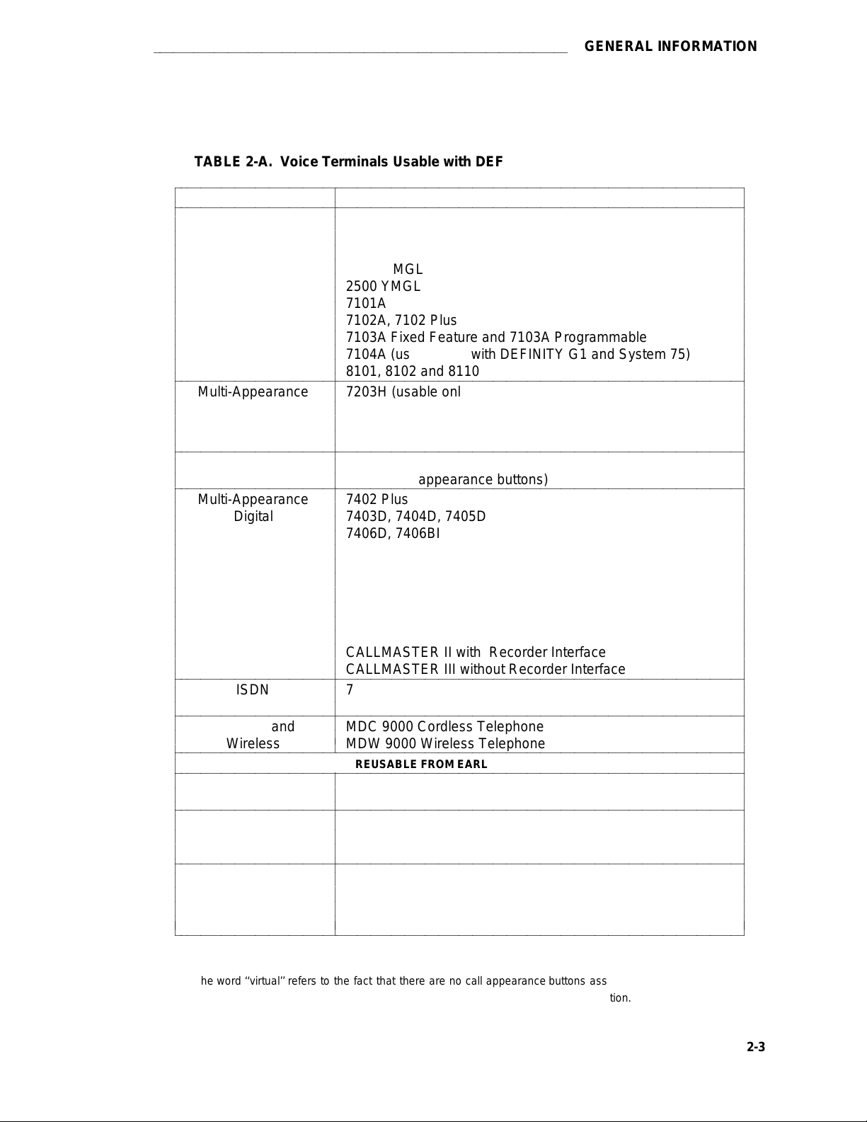
Table 2-A. Voice Terminals Usable with DEFINITY, System 75, and System 85 …………… 2-3
Table 2-B. Adjunct/Voice Terminal Compatibility ………………………………………………… 2-12
Table 2-C. Recommended Protectors……………………………………………………………… 2-22
Table 2-D. IROB Protection ………………………………………………………………………… 2-23
Table 2-E. Availability………………………………………………………………………………… 2-26
Table 2-F. DEFINITY G1 and System 75 Voice Terminal Administration ……………………… 2-40
Table 2-G. DEFINITY G1 and System 75 Terminal and Module Administration ……………… 2-44
Table 2-H. DEFINITY G2 and System 85 Voice Terminal Administration ……………………… 2-45
Table 2-I. DEFINITY G2 and System 85 Terminal and Module Administration ……………… 2-48
Table 3-A. Single-Line (and 7401) Voice Terminal Features …………………………………… 3-2
Table 3-B. Multi-Appearance Hybrid Voice Terminal Features ………………………………… 3-5
Table 3-C. Multi-Appearance Digital Voice Terminal Features ………………………………… 3-7
Table 3-D. Multi-Appearance ISDN Voice Terminal Features …………………………………… 3-13
Table 3-E. Default Softkey Features on the 8410 ………………………………………………… 3-259
Table 3-F. Alternate Softkey Features on the 8410 ……………………………………………… 3-260
Table 3-G. Default Softkey Features on the 8434 and 8434DX ………………………………… 3-283
Table 3-H. Alternate Softkey Features on the 8434 and 8434DX ……………………………… 3-284
xxxi
Page 34

Page 35
aaaaaaaaaaaaaaaaaaaaaaaaaaaaaaaaaaaaaaaaaaaaaaaaaaaaaaaaaaaaaaaaaaaaaaa
INTRODUCTION
INTRODUCTION
Purpose
Voice terminals and adjuncts are voice and data devices that are connected to the system switch
in a business communications system. This manual provides concise physical and functional
descriptions of the voice terminals/telephones, adjuncts, and data modules that can be used with
DEFINITY Generic 1, Generic 2, Generic 3, System 75, and System 85. The book is intended
as an aid for both AT&T and customer personnel in selecting appropriate components for these
systems and for the training of personnel and management of the system.
This issue replaces all previous issues of this document. The reason for reissue is to add more
information on the items included in previous issues of this document and to include the following
new items:
d
8101 Telephone
d
8403 (8403D01A) Voice Terminal
d
8410B (8410D02A) Voice Terminal (without a display)
d
8410D (8410D01A) Voice Terminal with display
d
8434 (8434D01A) Voice Terminal
d
CALLMASTER III Voice Terminal
d
MDC Cordless Telephone
d
MDW Wireless Telephone
In Issue 3, four new sections were added. The EXPOSED PORT PROTECTION section
discusses the different protection required for lightning protection. The AVAILABILITY section
lists the availability of the products covered in this manual. The ADJUNCT POWER section
discusses the different types of adjunct power supplies available. The ADMINISTRATION section discusses how to administer some of the newer terminals when the software of the version
switch being used does not contain the proper administration procedures for the new terminal.
The equipment covered in this manual includes the following specific groups:
d
Telephones/Voice Terminals
d
Adjuncts used with the voice terminals to enhance voice operations
d
Data Modules (adjuncts that support data operations)
d
PC Platforms (PC/PBX) and Application Software
Attendant consoles, applications processors (APs), printers, and data terminals used with APs
are not described in this manual.
Figure 1 shows a typical arrangement of terminals and adjuncts connected to the system switch.
1-1
Page 36

INTRODUCTION
aaaaaaaaaaaaaaaaaaaaaaaaaaaaaaaaaaaaaaaaaaaaaaaaaaaaaaaaaaa
FIGURE 1-1. Interface Between System Switch and Typical Terminals/Adjuncts
1-2
Page 37

aaaaaaaaaaaaaaaaaaaaaaaaaaaaaaaaaaaaaaaaaaaaaaaaaaaaaaaaaaaaaaaaaaaaaaa
INTRODUCTION
Organization
The remainder of this manual is divided into nine main sections; tabs are provided for convenient
access to each section. All equipment descriptions are supported by illustrations.
d
GENERAL INFORMATION—Gives background data that applies to the entire range of
equipment covered in this manual.
d
EXPOSED PORT PROTECTION—Contains information on the protection required by
exposed ports. This section also lists some of the AT&T protection devices and gives
parameters that non-AT&T devices must meet.
d
AVAILABILITY—Lists the ordering status of the equipment covered in this manual.
d
ADJUNCT POWER—Lists the different terminals and adjuncts that require adjunct
power supplies and the recommended adjunct power supply. Information has also been
added about the MSP-1 power supply.
d
ADMINISTRATION—When some of the newer terminals are used with some older ver-
sions of the switches, the administration of the switch does not allow for the use of the
new terminals. These new terminals must be administered using the administration pro-
cedures of a similar older terminal. This is called aliasing. This section contains the
aliasing information and the appropriate caveats.
d
VOICE TERMINALS—Provides detailed coverage of the main groups of voice terminals,
divided into eleven tabbed subsections. This section contains detailed information on
each voice terminal that can be ordered as a component of DEFINITY Generic 1, Gen-
eric 2, or Generic 3, or possibly all three. It also contains brief descriptions of voice ter-
minals that were previously installed in earlier business communications systems. Check
each description to see if these voice terminals are compatible with DEFINITY G1, G2, or
G3, System 75, and System 85.
1-3
Page 38

INTRODUCTION
The nine tabbed subsections and the voice terminals described in each subsection are
listed as follows:
7100 SERIES CALLMASTER
Model 7101A 602 CALLMASTER
Model 7102A CALLMASTER II
Model 7102 Plus CALLMASTER III
Model 7103A Fixed Feature
Model 7103A Programmable 500/2500 SERIES
Model 7104A Model 500 Series
7200 SERIES Model 2500 DMGC
Model 7203H Model 2500 YMGK
Model 7205H Model 2500 MMGL
7300 SERIES
Model 7303S 8100 SERIES
Model 7305S Model 8101
7400 SERIES Model 8110
Model 7401D
Model 7401 Plus ISDN VOICE TERMINALS
Model 7402 Plus Model 7505 ISDN
Model 7403D Model 7506 ISDN
Model 7404D Model 7507 ISDN
Model 7405D Model 8503T ISDN
Model 7406D Model 8510T ISDN
Model 7406BIS Model 8520T ISDN
Model 7406 Plus
Model 7407D CORDLESS AND WIRELESS TELEPHONES
Model Enhanced 7407D MDC 9000 Cordless Telephone
Model 7407 Plus MDW 9000 Wireless Telephone
Model 7410D
Model 7410 Plus OTHER
Model 7434D Voice terminals reusable
Model 7444 from other systems:
8400 SERIES 7305H01B, and 7305H02B
Model 8403 Multi-Button Electronic
Model 8410 Telephone (MET) Sets
Model 8434
aaaaaaaaaaaaaaaaaaaaaaaaaaaaaaaaaaaaaaaaaaaaaaaaaaaaaaaaaaa
Model 2500 Series
Model 2500 YMGL
Model 8102
Models 7203H, 7303H,
1-4
Page 39

aaaaaaaaaaaaaaaaaaaaaaaaaaaaaaaaaaaaaaaaaaaaaaaaaaaaaaaaaaaaaaaaaaaaaaa
d
ADJUNCTS—Contains information on the devices that can be used with voice terminals
to supplement services and features. This section contains information on the controls,
buttons, lights, and functions of DEFINITY G1, G2, G3, System 75, and System 85 voice
terminals and telephone adjuncts. Adjuncts that are identical in appearance and func-
tion, but have different codes, are covered under the same heading. Adjuncts that are
basically data modules are covered in the Data Modules section in this manual.
The adjuncts covered in this section are:
−Call Coverage Modules −Speakerphones
−Digital Display Module −Loudspeaker
−Function Key Module −Messaging Cartridge
−Headset Adapters −Automatic Dialer
−Message Waiting Indicator
d
DATA MODULES—Contains information on the devices that provide data communica-
tions interface. This section contains information on the data modules and other related
data equipment used with DEFINITY G1, G2, G3, System 75, and System 85. These
devices provide data interface functions which include modems, protocol converters, and
data units.
INTRODUCTION
The data modules covered in this section are:
−7400A Data Module −Modular Trunk Data
−7400B and 7400B Plus Module (MTDM)
Data Module −3270 Data Module
−7500B Data Module −Asynchronous Data Unit (ADU)
−ISDN Asynchronous Data −Multiple Asynchronous Data
Module (ADM) Unit (MADU)
−Digital Terminal Data −DCIU Interface Units
Module (DTDM) −2500-SERIES Data Service Unit
−Z702AL1 Data Service Unit −Modems (Data Sets)
−703A Data Service Unit −Local Distribution Service
−DEFINITY High Speed Link (HSL) Unit (LDSU)
−Processor Data Module (PDM) −Isolating Data Interface (DI)
−Trunk Data Module (TDM) −Protocol Converters
−Modular Processor Data
Module (MPDM)
d
PC Platforms (PC/PBX and PC/ISDN) and Application Software—Contains information on the different PC/PBX Platforms, the PC/PBX Connection, and E78 Plus/ISDN.
d
Blank Templates for Model Design—Includes blank templates of voice terminal
faceplates on which the Software Associate can designate the numbers, feature codes,
or features to be administered on each voice terminal button.
1-5
Page 40

INTRODUCTION
aaaaaaaaaaaaaaaaaaaaaaaaaaaaaaaaaaaaaaaaaaaaaaaaaaaaaaaaaaa
Page 41

aaaaaaaaaaaaaaaaaaaaaaaaaaaaaaaaaaaaaaaaaaaaaaaaaaaaaaaaaaaaa
GENERAL INFORMATION
GENERAL INFORMATION
This section provides general information on all of the equipment described in this manual. Information is provided on voice terminals, adjuncts, data modules, and data terminals. Detailed
information on these types of equipment can be found behind the tab for each particular type of
equipment.
Voice Terminals
The advanced, multi-appearance voice terminals combine the capabilities of both a telephone
and a terminal and have a variety of controlling and monitoring functions. While providing basic
telephone service (placing and answering calls), voice terminals can also be used to activate the
advanced features of the system.
This part explains higher level topics that apply to voice terminals as a group and contains
descriptions of facilities and characteristics that are common to all or most terminals. Table A
presents a summary of all voice terminals used with DEFINITY G1, G2, G3, System 75, and System 85.
The complete line of voice terminals are two basic types,
appearance voice terminals.
they access features and the way they receive calls.
The operational differences between these types are in the way
single-line voice terminals
and
multi-
Single-Line Voice Terminals
The term ‘‘single-line’’ means that only one incoming call can be ringing at an idle terminal. Once
an incoming call has been answered, however, a single-line voice terminal can handle both the
active call and another call on hold or waiting. When a single-line terminal user is busy on a call,
an incoming call does not ring but alerts the user via a ‘‘call waiting tone’’ (in the handset or
speakerphone) that a call is waiting to be answered. While a single-line terminal is occupied with
two calls, any other calls placed to the terminal get a busy tone.
All single-line voice terminals are analog in operation; that is, transmission of all signals between
the terminal and its port, at the system digital switch, is in analog form over a tip and ring pair of
wires. The port circuit provides analog/digital signal conversion. Power for these terminals is
supplied from the switch on the single voice pair. Single-line terminals have many applications
but are more limited in their access to system features than multi-appearance terminals.
2-1
Page 42

GENERAL INFORMATION
aaaaaaaaaaaaaaaaaaaaaaaaaaaaaaaaaaaaaaaaaaaaaaaaaaa
Multi-Appearance Voice Terminals
A multi-appearance voice terminal gives its user much more flexibility in handling calls than a
single-line voice terminal. A multi-appearance voice terminal, represented by a unique primary
extension number, has multiple call appearances (buttons with lights) where incoming calls to the
number can be answered and outgoing calls can be originated. Incoming calls can ring simultaneously at all appearances except for those translated as originate-only. As long as at least
one appearance is idle, callers will not receive busy tone. When all call appearances, except call
appearances translated as originate-only, are busy, callers will hear busy tone unless the incoming call is a priority call or the Restrict Last Appearance feature is deactivated. The terminal user
must decide the order to answer multiple incoming calls.
The two sub-types of multi-appearance voice terminals are digital and hybrid. Digital terminals
generate and receive voice and control signals in digital form. Connection between terminals and
the system switch is over 2-pair digital links; no conversion is necessary at the digital line port.
Hybrid terminals, as the name implies, combine analog and digital. They are connected to the
system switch by three pairs of links; on MET-like hybrid sets, one pair is for analog voice, and
the other two pairs are for digital control signals, and on ATL-like hybrid sets, one pair is for digital control signals, and the other two pairs are for analog voice. DC power for all multiappearance terminals (except for the 7404D and 7407D01B, which are AC powered) is conducted from the switch over the digital pairs.
Digital multi-appearance voice terminals have several important advantages over hybrids:
d
Digital voice terminals can support and control data terminals.
d
The Digital Communications Protocol (DCP) or ISDN-BRI interface between a digital
voice terminal and the system switch supports simultaneous voice and data calls over
the terminal’s standard mounting cord.
d
Digital terminals have a wider selection of adjuncts.
d
Call information displays are available with some digital voice terminals.
2-2
Page 43
aaaaaaaaaaaaaaaaaaaaaaaaaaaaaaaaaaaaaaaaaaaaaaaaaaaaaaaaaaaaa
GENERAL INFORMATION
TABLE 2-A. Voice Terminals Usable with DEFINITY, System 75, and System 85
bbbbbbbbbbbbbbbbbbbbbbbbbbbbbbbbbbbbbbbbbbbbbbbbbbbbbbbbbbbbbbbbbbbbbbbbbbbbbbbbbbbb
c
bbbbbbbbbbbbbbbbbbbbbbbbbbbbbbbbbbbbbbbbbbbbbbbbbbbbbbbbbbbbbbbbbbbbbbbbbbbbbbbbbbbb
c
c
c
TYPE MODEL
Single-Line 2500 Series
Analog 2500 DMGC
c
c
c
c
c
c
c
c
c
bbbbbbbbbbbbbbbbbbbbbbbbbbbbbbbbbbbbbbbbbbbbbbbbbbbbbbbbbbbbbbbbbbbbbbbbbbbbbbbbbbbb
c
Multi-Appearance 7203H (usable only with DEFINITY G2 and System 85)
c
c
Hybrid 7205H (usable only with DEFINITY G2 and System 85)
c
c
bbbbbbbbbbbbbbbbbbbbbbbbbbbbbbbbbbbbbbbbbbbbbbbbbbbbbbbbbbbbbbbbbbbbbbbbbbbbbbbbbbbb
c
Single-Appearance 7401D and 7401 Plus (have two virtual* appearances, but no
c
c
bbbbbbbbbbbbbbbbbbbbbbbbbbbbbbbbbbbbbbbbbbbbbbbbbbbbbbbbbbbbbbbbbbbbbbbbbbbbbbbbbbbb
c
c
c
Digital call appearance buttons)
Multi-Appearance 7402 Plus
Digital 7403D, 7404D, 7405D
c
c
c
c
c
c
c
c
c
c
bbbbbbbbbbbbbbbbbbbbbbbbbbbbbbbbbbbbbbbbbbbbbbbbbbbbbbbbbbbbbbbbbbbbbbbbbbbbbbbbbbbb
c
c
bbbbbbbbbbbbbbbbbbbbbbbbbbbbbbbbbbbbbbbbbbbbbbbbbbbbbbbbbbbbbbbbbbbbbbbbbbbbbbbbbbbb
c
c
c
bbbbbbbbbbbbbbbbbbbbbbbbbbbbbbbbbbbbbbbbbbbbbbbbbbbbbbbbbbbbbbbbbbbbbbbbbbbbbbbbbbbb
c
bbbbbbbbbbbbbbbbbbbbbbbbbbbbbbbbbbbbbbbbbbbbbbbbbbbbbbbbbbbbbbbbbbbbbbbbbbbbbbbbbbbb
c
c
c
bbbbbbbbbbbbbbbbbbbbbbbbbbbbbbbbbbbbbbbbbbbbbbbbbbbbbbbbbbbbbbbbbbbbbbbbbbbbbbbbbbbb
c
c
c
c
bbbbbbbbbbbbbbbbbbbbbbbbbbbbbbbbbbbbbbbbbbbbbbbbbbbbbbbbbbbbbbbbbbbbbbbbbbbbbbbbbbbb
c
Multi-Button Electronic 10 Button with or without Built-In Speakerphone
c
Telephone (MET) Sets 20 Button
c
ISDN 7505, 7506, 7507 (usable only with DEFINITY)
Terminals 8503T, 8510T, 8520T (usable only with DEFINITY G2 and G3)
Cordless and MDC 9000 Cordless Telephone
Wireless
Single-Line 500 (can also be ordered new)
Analog 2500 Series (can also be ordered new)
Multi-Appearance 7305H
Hybrid 7305H01B
(MERLIN) 7305H02B
c
c
bbbbbbbbbbbbbbbbbbbbbbbbbbbbbbbbbbbbbbbbbbbbbbbbbbbbbbbbbbbbbbbbbbbbbbbbbbbbbbbbbbbbc
c
c
c
c
2500 YMGK
c
c
2500 MMGL
c
2500 YMGL
c
7101A
c
7102A, 7102 Plus
c
7103A Fixed Feature and 7103A Programmable
c
c
7104A (usable only with DEFINITY G1 and System 75)
c
8101, 8102 and 8110
c
c
c
c
7303S
c
7305S
c
c
c
c
c
c
7406D, 7406BIS, 7406 Plus
c
7407D, Enhanced 7407D, 7407 Plus
c
c
7410D, 7410 Plus
c
7434D
c
7444
c
8403, 8410 (with or without display), 8434
c
602A, 602D CALLMASTER
c
CALLMASTER II with Recorder Interface
c
c
CALLMASTER III without Recorder Interface
c
c
c
c
c
MDW 9000 Wireless Telephone
c
REUSABLE FROM EARLIER SYSTEMS
c
c
c
c
c
c
c
c
c
30 Button
c
c
7203M (12 button)
c
c
c
c
c
c
c
c
c
c
c
c
c
c
c
c
c
c
c
c
c
c
c
c
c
c
c
c
c
c
c
c
c
c
c
c
c
c
c
c
c
c
c
c
c
c
c
c
c
c
c
c
c
c
* The word ‘‘virtual’’ refers to the fact that there are no call appearance buttons associated with either appearance.
Refer to the description of the 7401D and 7401 Plus Voice Terminal for more information.
2-3
Page 44

GENERAL INFORMATION
aaaaaaaaaaaaaaaaaaaaaaaaaaaaaaaaaaaaaaaaaaaaaaaaaaa
Facilities Common to All Voice Terminals
Every DEFINITY G1, G2, G3, System 75, and System 85 voice terminal has the following equipment:
d
A pushbutton pad for touch-tone dialing (except for the Model 500, which has a rotary
dial)
d
A handset with a coiled modular cord
d
A 7-foot modular mounting cord (except for the Model 2554 wall set).
Buttons
All multi-appearance voice terminals and most single-line terminals have buttons for handling
calls and activating various functions that enhance basic calling.
Fixed Feature Buttons
Buttons that are factory labeled and require no administration are referred to as fixed feature buttons. The following buttons, in several combinations, are found on most voice terminals. They
are dedicated to standard calling functions and are located adjacent to or above the pushbutton
dial pad for calling convenience.
Note: Fixed feature buttons that are limited to a small number of terminals are explained in
the detailed descriptions of those terminals.
d
Recall Button (on older sets)—provides a timed flash that is more accurate than a
manual switchhook flash and prevents accidental dropping of calls. The following list of
uses for this button is only valid for single-line terminals:
Put an active call on hold and obtain recall dial tone for making another call.
Disconnect from a second call and return to a call on hold, when pressed twice.
Place an active call on hold and answer a waiting call using Dial Access Code,
then toggle between the two calls (using the Recall button and Dial Access
Code).
Place an active call on hold; receive recall dial tone, and dial the Feature Access
Code to answer a waiting call. Toggle between the two calls by performing the
same action.
Add a party, previously put on hold, to a conference with a third party.
2-4
Drop the party previously added.
d
Disconnect Button (on older sets)—allows the terminal user, after completing one call, to
permanently disconnect from the call and get dial tone for placing a new call without
going on- and off-hook. On System 85 and DEFINITY G2, depending on the administration, this button can be used to reconnect to the call on hold on multiple appearance
voice terminals.
Page 45

aaaaaaaaaaaaaaaaaaaaaaaaaaaaaaaaaaaaaaaaaaaaaaaaaaaaaaaaaaaaa
d
Hold Button—is used to temporarily disconnect from one call, without dropping it, so that
another call can be answered or originated. The user can return to the call on hold.
d
Drop Button—is used to permanently disconnect the last party added to a conference
call. On System 85 and DEFINITY G2, this button also gives dial tone on the same call
appearance if dialing or on a 2-party call.
Note: On some voice terminals, this button is also used to perform a test of the
voice terminal‘s lights, ringer, and display (if the terminal has one).
d
Conference Button—enables the terminal user to set up a conference call by adding new
calls to an existing 2-party connection. The user can add as many as five calls to a
conference. (On System 85 and DEFINITY G2 the user can only build a 3-party conference call using this button; 6-party conference calls can be built by the attendant.)
Note: On some voice terminals, this button is also used to select a personalized
ring from 8 available ringing patterns.
GENERAL INFORMATION
d
Transfer Button—enables the terminal user to shift an active call to another voice termi nal.
d
Select Ring Button (on older sets)—enables the terminal user to select a personalized
ringing pattern.
d
Speaker Button—turns on either a listen-only speaker or a 2-way speakerphone which
allows the user to speak and listen to the far-end party.
Note: On some voice terminals, this button also allows the user to initiate an
acoustic test of the surrounding environment (the Reset Speakerphone
feature) through a series of tones. When the tones stop, the speakerphone
has finished adjusting itself for optimal performance.
d
Mute Button—turns off the microphone of the built-in speakerphone or the handset so
the other person on the call cannot hear you.
Administrable Buttons
Buttons that are not fixed feature buttons are administered (or assigned) by the System Manager
or the terminal user for many functions. Buttons that may be administered include call
appearance/feature buttons and feature-only buttons.
Every multi-appearance voice terminal has a minimum of three buttons while others have as
many as 34 buttons that can be administered as call appearances, that is, positions for answering incoming calls and originating outgoing calls (see Figure 1). In DEFINITY G1 and System
75, software defaults the first three of these buttons for appearances of the terminal’s primary (or
home) extension number; the System Manager has the option of administering Button #3 differently. In DEFINITY G2 and System 85, no buttons are defaulted for the primary extension
number; the System Manager
must
administer all the required positions. Buttons not used for
the primary extension number can be assigned as appearances of other extensions or for activating optional features.
2-5
Page 46

GENERAL INFORMATION
Example shows button field of 7410 Plus voiceterminal. Other terminals may have differentarrangements, but Buttons 1, 2, and 3 arealways present.1.NOTE:
aaaaaaaaaaaaaaaaaaaaaaaaaaaaaaaaaaaaaaaaaaaaaaaaaaa
FIGURE 2-1. Call Appearance/Feature Buttons
Associated with each call appearance/feature button is a pair of lights that provide information on
the availability and status of the appearance. These lights are described in the next part of this
manual (titled ‘‘Lights’’).
Any button that can be administered and is not used for a call appearance can be assigned to an
optional feature. Included in this category are buttons with two lights (call appearance/feature
buttons) and buttons with one or no lights, intended specifically for features. Some features
require light feedback to inform the terminal user when the feature is active; others are simple,
one-time operations for which light feedback would be meaningless. Good feature administration
matches features to appropriate buttons whenever possible.
2-6
Page 47

aaaaaaaaaaaaaaaaaaaaaaaaaaaaaaaaaaaaaaaaaaaaaaaaaaaaaaaaaaaaa
GENERAL INFORMATION
Lights
Indicator lights provide silent visual reminders to the voice terminal user regarding lines, features,
and messages taken at other locations. The lights on DEFINITY G1, G2, G3, and System 75 and
85 voice terminals are light-emitting diodes (LEDs) or neon lights.
On all multi-appearance voice terminals, each call appearance/feature button has two indicator
lights: a red light and a green status light. When a call appearance/feature button is used for a
feature, only the status light is operational; the red light remains off at all times. Feature-only buttons have either a single green status light or no light at all. The various arrangements of red and
green lights are shown in Figure 2.
GREEN STATUSLIGHTREDLIGHTRED LIGHTGREENSTATUSLIGHTTWO STYLES OF LIGHTARRANGEMENT FORCALL APPEARANCE/FEATUREBUTTONSTWO STYLES OF LIGHTARRANGEMENT FORFEATURE-ONLYBUTTONSGREENSTATUSLIGHTGREENSTATUSLIGHT
FIGURE 2-2. Button Lights
2-7
Page 48
GENERAL INFORMATION
aaaaaaaaaaaaaaaaaaaaaaaaaaaaaaaaaaaaaaaaaaaaaaaaaaa
Red Light
The red light normally has two states: lighted steadily or dark (off).* One red light is always on at
a multi-appearance voice terminal when the handset is on hook. It identifies the call appearance
the user will be automatically connected to if the handset is lifted. When the handset is lifted, the
red light identifies the call appearance that is active.
The red light is off when the handset is lifted but not connected to a call appearance; for example,
when one call has been put on hold but another call appearance button has not been pressed.
When certain features such as Preselection, Idle Line Originating preference, or No Line Originating Preference are administered, the red light is also off while on hook.
Green Status Light
The green status light can indicate any one of the following six conditions:
d
Off—the call appearance is idle or the assigned feature is not activated.
d
Lighted steadily—the call appearance is busy or the assigned feature is active.
d
Flashing (slow on-off for equal periods, one cycle per second)—an unanswered incoming
call on that call appearance.
d
Fluttering (fast on-off for equal periods, 10 cycles per second)—a call placed on hold on
that call appearance by the voice terminal user.
d
Broken Fluttering (fast on-off modulated at the slow rate)—feature denial to the calling
voice terminal or an unknown or invalid action.
d
Winking (long on-short off at about three cycles per second)—a call placed on hold from
another voice terminal or an action pending.
Message Light
The Message light, when on, indicates that a message is waiting for the voice terminal’s user (for
example, Leave Word Calling or voice mail messages). When the user retrieves the message,
the light is automatically turned off.
aaaaaaaaaaaaaaaaaaa
* On the ISDN-BRI 7505, 7506, and 7507 sets, the red light flashes when the set is using phantom power.
2-8
Page 49

aaaaaaaaaaaaaaaaaaaaaaaaaaaaaaaaaaaaaaaaaaaaaaaaaaaaaaaaaaaaa
GENERAL INFORMATION
Tones
The tones that a voice terminal user hears can be divided into two categories:
d
Ringing Tones—those that are generated in the base of the voice terminal and can be
heard in the surrounding area; they indicate incoming calls.
d
Handset Tones—those that are transmitted through the handset and heard only by the
user or through the speakerphone when it is turned on.
External Ringing Tones
Ringing tones are the only tones heard
outside the voice terminal
when it is receiving a call. This
signal cycles in 1-, 2-, or 3-ring patterns. On System 75 and DEFINITY G1 and G3, only one
cycle of ringing is heard if the multi-appearance voice terminal is busy with another call. On System 85 and DEFINITY G2, the cycling repeats (except on the ISDN 7500-series sets).
d
One ring—a call from another voice terminal in the system
d
Two rings—a call from the attendant or outside caller
d
Three rings—priority calls, for example, Automatic Callback, Priority Calling, or Ringback
from a queued call
d
One short unmodulated tone—an intercom call
d
Ring-Ping (half ring)—a call redirected away from the voice terminal because Send All
Calls or Call Forwarding is active; also called coverage tone.
d
On System 85 and DEFINITY G2, any of these external tones, plus a repeated unmodulated tone, may be administered to indicate an intercom call.
Handset Tones
The following tones are heard through the handset:
d
Answer Tone—a high-pitched continuous tone indicating that a data endpoint has
answered.
d
Busy Tone—a low-pitched tone repeated 60 times a minute; indicates that the number
dialed is in use.
d
Call Waiting Tone (Single-Line Voice Terminals)—one, two, or three beeps (short
bursts of high-pitched tone), not repeated; indicates to the user at a busy single-line terminal that an incoming call is waiting to be answered. The number of beeps indicates the
source of the waiting call:
One beep—a call from another voice terminal in the system
Two fast beeps—a call from the attendant or an outside caller
Three fast beeps—a priority call
2-9
Page 50

GENERAL INFORMATION
d
Confirmation Tone—(three short bursts of tone) indicates that a feature activation or
cancellation has been accepted, or that an outgoing call from a single-line voice terminal
has been placed in a ringback queue.
d
Coverage Tone—(one long burst of tone) indicates to the calling party that a call to an
extension number will be answered at another extension number by a covering user.
d
Dial Tone—(a continuous steady tone) indicates that dialing or feature activation can
begin.
d
Intercept Tone—(an alternating high and low tone) indicates either a dialing error or a
denial of the service requested.
d
Recall Dial Tone—(three short bursts of dial tone followed by steady dial tone) indicates
that the feature requested has been accepted and dialing can start.
d
Recorded Telephone Dictation Ready Tone—(a high-pitched continuous tone) indicates that a dictation machine has been connected to the voice terminal.
d
Reorder Tone—(a fast-busy tone repeated 120 times a minute) indicates that all outgoing trunks are busy or feature resource is not available. Try again.
aaaaaaaaaaaaaaaaaaaaaaaaaaaaaaaaaaaaaaaaaaaaaaaaaaa
d
Ringback Tone—(a low-pitched tone repeated 15 times a minute) indicates to the calling
party that the number dialed has been reached successfully and is ringing.
d
Ringback Tone, Call Waiting—(a ringback tone with a short lower-pitched signal at the
end) indicates to the calling party that the extension called is busy, but that the called
party has been given the call waiting signal.
d
Time-Out Tone—[an alternating high and low tone (same as intercept tone)] indicates a
failure to dial within a preset interval (usually 10 seconds) after lifting the handset or after
dialing the previous digit.
d
Warning Tone (Bridging)—(a low-pitched tone heard by all parties in a Busy Verification
attempt that bridges on to an active call) initially applied in a 2-second (System 75 and
G1) or 4-second (System 85 and G2) burst, then in half-second bursts every 15 seconds.
Desk/Wall Mounting Arrangements
All the voice terminals covered in this manual, except the Model 2554, are intended for freestanding desktop use. However, wall-mounting is feasible for many terminals and appropriate
kits are available. The detailed description of each voice terminal contains wall-mounting information and limitations.
2-10
Page 51

aaaaaaaaaaaaaaaaaaaaaaaaaaaaaaaaaaaaaaaaaaaaaaaaaaaaaaaaaaaaa
GENERAL INFORMATION
Adjuncts
Adjuncts are optional devices that extend the existing capabilities of voice terminals or provide
new services. Some adjuncts are physically attached to their voice terminals, and others are
free-standing, connected by way of mounting cords. The adjuncts have styling and colors that
are compatible with the associated voice terminals.
Table B provides a cross-reference between adjuncts and the voice terminals with which they are
used. The following limitations apply to the use of multiple adjuncts:
d
A speakerphone and a headset adapter cannot be connected to the same voice terminal
simultaneously because they plug into the same jack on the terminal.
d
A C401A Call Coverage Module and a D401A Digital Display Module cannot be mounted
on the same 7405D or 7434D Voice Terminal simultaneously because they attach to the
same part of the terminal.
None of the adjuncts have facilities for wall mounting, and wall-mounting kits are not available.
However, the modules (call coverage, function key, and digital display) are attached to their voice
terminals, which can then be mounted on a wall. Free-standing adjuncts (speakerphones and
headset adapters) associated with wall-mounted terminals can be placed on a nearby shelf or
table.
2-11
Page 52
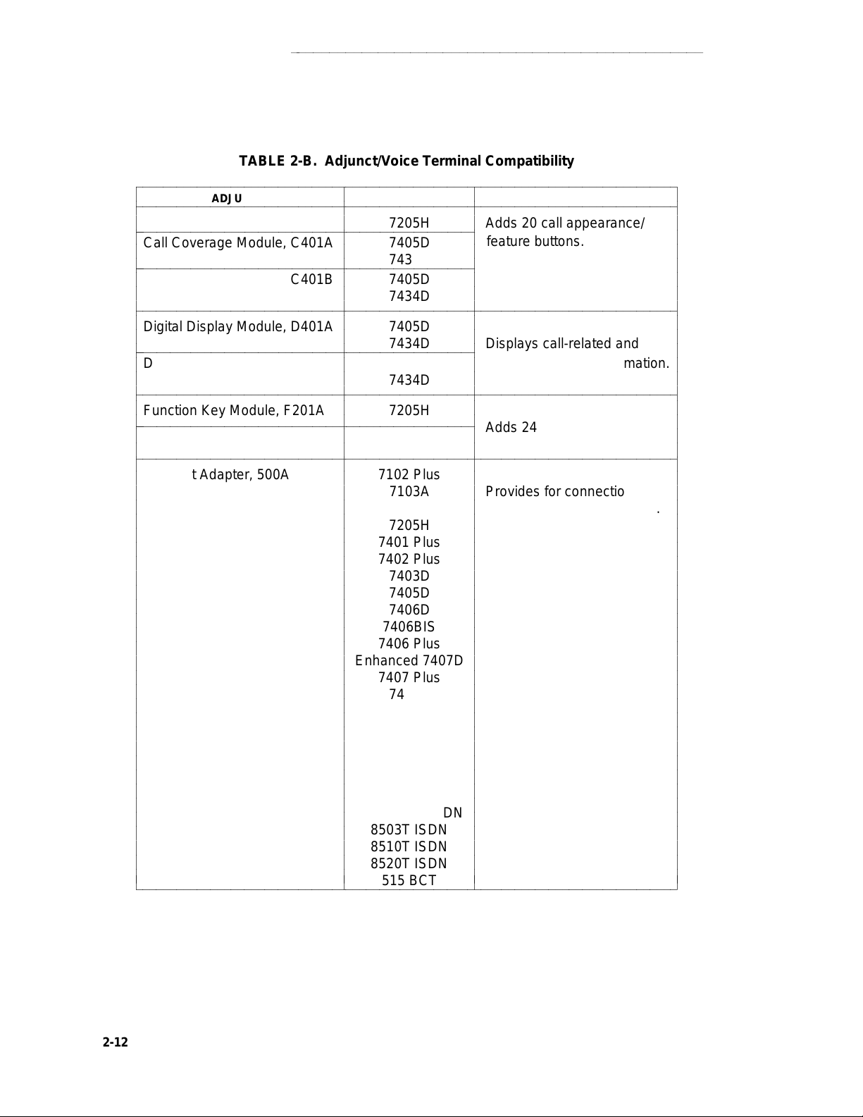
GENERAL INFORMATION
aaaaaaaaaaaaaaaaaaaaaaaaaaaaaaaaaaaaaaaaaaaaaaaaaaa
TABLE 2-B. Adjunct/Voice Terminal Compatibility
bbbbbbbbbbbbbbbbbbbbbbbbbbbbbbbbbbbbbbbbbbbbbbbbbbbbbbbbbbbbbbbbbbbbbbbbbbbbbbbb
c
bbbbbbbbbbbbbbbbbbbbbbbbbbbbbbbbbbbbbbbbbbbbbbbbbbbbbbbbbbbbbbbbbbbbbbbbbbbbbbbb
c
Call Coverage Module, C201A 7205H Adds 20 call appearance/
c
bbbbbbbbbbbbbbbbbbbbbbbbbbbbbbbbbbbbbbbbbbbbbbbbbbb
c
Call Coverage Module, C401A 7405D
c
bbbbbbbbbbbbbbbbbbbbbbbbbbbbbbbbbbbbbbbbbbbbbbbbbbb
c
Call Coverage Module, C401B 7405D
c
c
bbbbbbbbbbbbbbbbbbbbbbbbbbbbbbbbbbbbbbbbbbbbbbbbbbbbbbbbbbbbbbbbbbbbbbbbbbbbbbbb
c
c
Digital Display Module, D401A 7405D
c
bbbbbbbbbbbbbbbbbbbbbbbbbbbbbbbbbbbbbbbbbbbbbbbbbbb
c
Digital Display Module, D401B 7405D personal service information.
c
c
bbbbbbbbbbbbbbbbbbbbbbbbbbbbbbbbbbbbbbbbbbbbbbbbbbbbbbbbbbbbbbbbbbbbbbbbbbbbbbbb
c
c
Function Key Module, F201A 7205H
bbbbbbbbbbbbbbbbbbbbbbbbbbbbbbbbbbbbbbbbbbbbbbbbbbb
c
c
Function Key Module, F401A 7405D
c
bbbbbbbbbbbbbbbbbbbbbbbbbbbbbbbbbbbbbbbbbbbbbbbbbbbbbbbbbbbbbbbbbbbbbbbbbbbbbbbb
c
Headset Adapter, 500A 7102 Plus
c
ADJUNCT TERMINALS FUNCTION
c
c
c
c
c
c
c
c
c
c
c
c
c
c
c
c
c
c
c
c
c
c
c
c
c
c
c
c
bbbbbbbbbbbbbbbbbbbbbbbbbbbbbbbbbbbbbbbbbbbbbbbbbbbbbbbbbbbbbbbbbbbbbbbbbbbbbbbbc
c
c
c
c
c
c
7434D
c
c
7434D
c
c
c
c
7434D Displays call-related and
c
c
7434D
c
c
c
c
c
c
c
c
c
c
c
c
c
c
c
c
c
c
c
c
c
c
c
c
c
c
c
c
c
c
c
c
c
c
c
c
7103A Provides for connection and
7203H control of standard headset.
7205H
7401 Plus
7402 Plus
7403D
7405D
7406D
7406BIS
7406 Plus
Enhanced 7407D
7407 Plus
7410D
7410 Plus
7434D
7444
8403, 8410, 8434
CALLMASTER
8102
7505,06,07 ISDN
8503T ISDN
8510T ISDN
8520T ISDN
515 BCT
c
c
c
c
feature buttons.
c
c
c
c
c
c
c
c
c
c
c
c
c
Adds 24 feature buttons.
c
c
c
c
c
c
c
c
c
c
c
c
c
c
c
c
c
c
c
c
c
c
c
c
c
c
c
c
c
c
c
c
c
c
c
c
c
c
c
c
c
c
c
c
c
c
c
c
c
c
c
c
c
c
c
c
c
c
c
c
c
c
c
c
c
c
c
c
c
c
c
c
c
c
c
c
c
c
c
c
c
c
c
2-12
Page 53

aaaaaaaaaaaaaaaaaaaaaaaaaaaaaaaaaaaaaaaaaaaaaaaaaaaaaaaaaaaaa
GENERAL INFORMATION
TABLE 2-B
(continued).
Adjunct/Voice Terminal Compatibility
bbbbbbbbbbbbbbbbbbbbbbbbbbbbbbbbbbbbbbbbbbbbbbbbbbbbbbbbbbbbbbbbbbbbbbbbbbbbbbb
c
bbbbbbbbbbbbbbbbbbbbbbbbbbbbbbbbbbbbbbbbbbbbbbbbbbbbbbbbbbbbbbbbbbbbbbbbbbbbbbb
c
Headset Adapter, 502A 7303S Provides for connection and
c
c
bbbbbbbbbbbbbbbbbbbbbbbbbbbbbbbbbbbbbbbbbbbbbbbbbbbbbbbbbbbbbbbbbbbbbbbbbbbbbbb
c
c
Message Waiting Indicator, Z34A 2500 Indicates that a message
c
c
bbbbbbbbbbbbbbbbbbbbbbbbbbbbbbbbbbbbbbbbbbbbbbbbbbbbbbbbbbbbbbbbbbbbbbbbbbbbbbb
c
Messaging Cartridge 7404D Provides display of
c
ADJUNCT TERMINALS FUNCTION
c
c
c
bbbbbbbbbbbbbbbbbbbbbbbbbbbbbbbbbbbbbbbbbbbbbbbbbbbbbbbbbbbbbbbbbbbbbbbbbbbbbbb
c
PC/PBX Plug-in Cartridge 7404D Provides interface with PCs.
c
bbbbbbbbbbbbbbbbbbbbbbbbbbbbbbbbbbbbbbbbbbbbbbbbbbbbbbbbbbbbbbbbbbbbbbbbbbbbbbb
c
c
Speakerphone, S101A Same as Provides hands-free calling.
c
Speakerphone, S201A 500A
c
c
c
bbbbbbbbbbbbbbbbbbbbbbbbbbbbbbbbbbbbbbbbbbbbbbbbbbbbbbbbbbbbbbbbbbbbbbbbbbbbbbb
c
Speakerphone, S102A Same as Provides hands-free calling.
c
Speakerphone, S202A 502A Provides improved voice quality
c
c
c
bbbbbbbbbbbbbbbbbbbbbbbbbbbbbbbbbbbbbbbbbbbbbbbbbbbbbbbbbbbbbbbbbbbbbbbbbbbbbbb
c
c
Speakerphone, 4A 2500 Provides hands-free calling.
c
c
Speakerphone, 203A Analog or Provides hands-free answering.
c
c
c
Loudspeaker, 107 2500 when not used as standalone.
c
c
c
bbbbbbbbbbbbbbbbbbbbbbbbbbbbbbbbbbbbbbbbbbbbbbbbbbbbbbbbbbbbbbbbbbbbbbbbbbbbbbb
c
Automatic Dialer, 2870A1 MET Provides the capability to
c
c
c
bbbbbbbbbbbbbbbbbbbbbbbbbbbbbbbbbbbbbbbbbbbbbbbbbbbbbbbbbbbbbbbbbbbbbbbbbbbbbbbc
c
c
c
c
7305S control of standard headset.
c
c
c
c
c
c
c
c
c
c
c
c
c
c
c
Headset
c
Adapter
c
c
c
c
c
Headset by adapting to room acoustics.
c
Adapter
c
c
c
c
c
standalone Provides hands-free calling
c
c
c
c
c
c
c
c
c
c
c
c
c
c
c
c
c
has been left for the terminal.
c
c
c
call-related and personal
c
service information on
c
c
data terminal screen.
c
c
c
c
c
c
c
c
c
c
c
c
c
c
c
c
c
c
c
c
c
Provides amplification for
c
the received voice signal.
c
c
c
to record and automatically
c
c
dial 31 numbers.
c
c
c
c
c
c
c
c
c
c
c
c
c
c
c
c
c
c
c
c
c
c
c
c
c
c
c
c
c
c
c
c
c
c
c
c
c
c
c
c
c
c
Several power supplies and connection schemes are available for providing auxiliary adjunct
power when it is required. Refer to the ADJUNCT POWER section of this manual for more information on these power sources.
2-13
Page 54

GENERAL INFORMATION
aaaaaaaaaaaaaaaaaaaaaaaaaaaaaaaaaaaaaaaaaaaaaaaaaaa
Data Modules
Data modules provide an interface between the system’s digital switch and Data Terminal Equipment (DTE) or Data Communications Equipment (DCE). DTE is defined as a data source or a
data link or a combination of both; typical examples are data terminals and host computers. DCE
is equipment that provides the functions for establishing, maintaining, and terminating a data call;
a modem is an example of DCE.
An interface device between the switch and DTE or DCE is necessary because the set of data
transmission rules and formats—the data protocol—at the switch is different from the protocol at
the DTE or DCE. The digital ports of the switch present a Digital Communications Protocol
(DCP) or ISDN-BRI interface to all devices connected to them. DCP supports simultaneous
voice and data communications by multiplexing the two sets of signals into one digital stream.
Digital voice terminals and some data terminals can be connected directly to the switch. But, if a
data endpoint has a different protocol (EIA RS-232C or RS-232D is the most common) than the
switch, a data module must be inserted to provide compatibility. The data module provides the
two-way data signal conversion and processing required between different protocols. Figure 3
shows a simplified diagram of the components of a typical data link.
DEFINITY G1, G2, G3SYSTEM 75ORSYSTEM 85DIGITALSWITCHV.35RS-449V .35RS-449RS-232C/DRS-232C/D
FIGURE 2-3. Data Link Components
The connection between a data module and a data endpoint must always have a DCE or DTE
interface. If the endpoint is a DCE, the data module must present a DTE interface to it. If the
endpoint is a DTE, then the data module must present a DCE interface. In general, modules are
classified as DCE- or DTE-type according to the kind of data endpoint to which they are connected.
Data modules are available to match a wide variety of data needs:
d
Asynchronous operation at data rates from 0.3-19.2 kbps and even, odd, mark/space,
zero/one or no parity options
d
Synchronous operation at data rates of 0.3, 1.2, 2.4, 4.8, 9.6, 19.2, 56, and 64 kbps
2-14
d
Half- or full-duplex operation and internal or external timing options at the appropriate
data rates
Page 55

aaaaaaaaaaaaaaaaaaaaaaaaaaaaaaaaaaaaaaaaaaaaaaaaaaaaaaaaaaaaa
GENERAL INFORMATION
The following data equipment is available with DEFINITY G1, G2, G3, System 75, and System
85:
d
7400A Data Module—In DTE mode, works with asynchronous DCE in the modem pool
at data rates of 0.3-19.2 kbps, full-duplex. Supports both Hayes-compatible and
D-lead modems. In DCE mode, the 7400A has Hayes, Keyboard Dial or Answer-Only
interface. Also works with asynchronous DTE where rack mounting is needed. Takes
the place of MTDM or MPDM in asynchronous applications.
d
7400B and 7400B Plus Data Modules—Works with asynchronous DTE at data rates of
0.3-19.2 kbps, full-duplex. Can be used with most 7400-series DCP voice terminals for
simultaneous voice/data or standalone. Emulates a Hayes-compatible modem, therefore, can be used with standard PC communications packages. Takes the place of previous DCP asynchronous data stands.
d
Modular Processor Data Module (MPDM)—Works with synchronous DTE at data rates
of 0.3-64 kbps. Also works at full- or half-duplex with internal or external timing at the
appropriate data rates. Supports V.35, RS-232, and RS-449 interfaces and RS-366
Automatic Calling Unit interface at the previously mentioned rates. Video codes are an
example of 56 or 64 kbps endpoints where calls are set up via the RS-366 interface. The
MPDM also supports asynchronous applications, but the 7400B Plus supersedes it for
applications requiring Hayes emulation and the 7400A supersedes it for remaining asynchronous applications.
d
Modular Trunk Data Module (MTDM)—Works with a synchronous DCE in modem pool
applications at data rates of 0.3-19.2 kbps. Also works at full- or half-duplex with internal
or external timing at the appropriate synchronous data rates. The 7400A supersedes it
for asynchronous applications.
d
7500B Data Module—Works with asynchronous or synchronous DCE or DTE on BRI
switch interface (DEFINITY G2 or 5ESS switch only). Supports RS-232 and V.35 interfaces and RS-366 Automatic Calling Unit interface (for the RS-232 interface only).
d
ISDN Asynchronous Data Module (ADM)—Works with asynchronous DTE as a data
stand for 7500-series BRI phones (DEFINITY G2 and 5ESS switch only). Supports
Hayes command set for compatibility with PC communications packages.
d
Definity High Speed Link—Works with synchronous V.35 DTE at data rates of 56 kbps
half or full duplex or 64 Kbps full duplex. Supports Permanent (private line type) calls
and switched calls. Switched calls can be set up using either the RS-366 or RS-232
(Hayes ATD command) interface; via DTR or Hotline dialing; or manually using the front
panel call control feature. Replaces the ACCUNET MPDM for video, LAN, CC/FEP
and other high speed applications.
d
Asynchronous Data Unit (ADU)—Works with asynchronous DTE at data rates of 0.3-
19.2 kbps. Used where the user has an analog voice phone and needs basic capabilities
for asynchronous terminals as opposed to PCs. Connects to SN 238 (System 85 and
DEFINITY G2 traditional modules) or TN726 (System 75 and DEFINITY G1 and G2
universal modules).
d
Multiple Asynchronous Data Unit (MADU)—Works with asynchronous DTE at data
rates of 0.3-19.2 kbps in host applications. The MADU is rack-mounted and supports
busy-out. It connects to the same switch ports as the ADU.
2-15
Page 56

GENERAL INFORMATION
d
2500-Series Data Service Unit (DSU), Isolating Data Interface (IDI), and Local Distribution Service Unit (LDSU)—DCIU interface units for DEFINITY G2 and System 85.
d
PC Platform Products:
aaaaaaaaaaaaaaaaaaaaaaaaaaaaaaaaaaaaaaaaaaaaaaaaaaa
PC/PBX Platform—PC expansion cards and software for XT/AT bus and
MicroChannel
TM
bus PCs in the DCP environment. Supports common, open data interface with PC/ISDN platform. Supported software includes PC/PBX Connection (for
advanced phone management, access to synchronous and asynchronous hosts, and
high-speed PC-to-PC communication) and E78 Plus. Works with any 7400-series
phone.
PC/ISDN Platform—PC expansion card and software for XT/AT bus PCs in the BRI
environment (DEFINITY G2 and 5ESS). Supports common, open data application interface with PC/PBX Platform. Supported software includes E78 Plus and high-speed
PC-to-PC file transfer applications.
E78 Plus/ISDN—Software written to the open data applications interface which provides
full 3270 terminal emulation and fast file transfer in IBM environments.
3270 Data Module—The 3270C Data module connects to an IBM 3274 or 3174 Clus-
ter Controller and converts DCP data from the PC platform products to the IBM Coax A
format to access IBM mainframes for 3270 terminal emulation and fast file transfer.
The above PC platform products allow PC users to:
Dial calls from the PC and use customized phone features from the keyboard,
including a personalized phone directory, log of calls received and made, notetaking on calls, and phone message retrieval.
Connect to a variety of asynchronous hosts and to IBM mainframes, allowing file
transfer to and from the mainframe using standard IBM file transfer protocols and
the standard DCA IRMA board user interface.
2-16
Transfer files from PC to PC at rates up to 1.2 kbps over a 64 kbps facility using
a PC package from Hilgraeve, Inc.
Switch back and forth from the above capabilities to DOS programs at the touch
of a key, when the PC/PBX application is run in the background.
Page 57

aaaaaaaaaaaaaaaaaaaaaaaaaaaaaaaaaaaaaaaaaaaaaaaaaaaaaaaaaaaaa
GENERAL INFORMATION
Data Terminals
A data terminal is a workstation at which data is entered and retrieved; it communicates through
lines, trunks, switches, and data modules with data endpoints such as computers and other data
terminals. Some data terminals contain built-in voice capabilities similar to digital voice terminals.
For detailed information on buttons, lights, and tones, refer to the general information about voice
terminals at beginning of this section.
The following data terminals are available with System 75, System 85, and DEFINITY G1 and
G2:
d
AT&T Personal Terminal 510A (no longer manufactured)(DA)
d
AT&T Personal Terminal 510D (no longer manufactured)(DA)
d
Model 513 Business Communications Terminal (BCT) (no longer manufactured)(DA)
d
Model 515 BCT (no longer manufactured)(DA)
d
Model 610 BCT
d
Model 615 MT
The 513 BCT, 610 BCT, and 615 MT, in addition to being optional units of peripheral equipment,
are used in DEFINITY G1 and System 75 as System Access Terminals (SATs). The SAT is
dedicated to system administration and maintenance and is located in or nearby the equipment
room with the DEFINITY G1 or System 75. This manual does not cover the 513, 610, or 615 as
an SAT but only as peripheral data terminals used for sending and receiving data calls.
Technical Specifications
Technical specifications are provided for the call progress tones, external ringing tones, and indicator light signals that are used with DEFINITY G1, G2, G3, System 75, and System 85.
2-17
Page 58
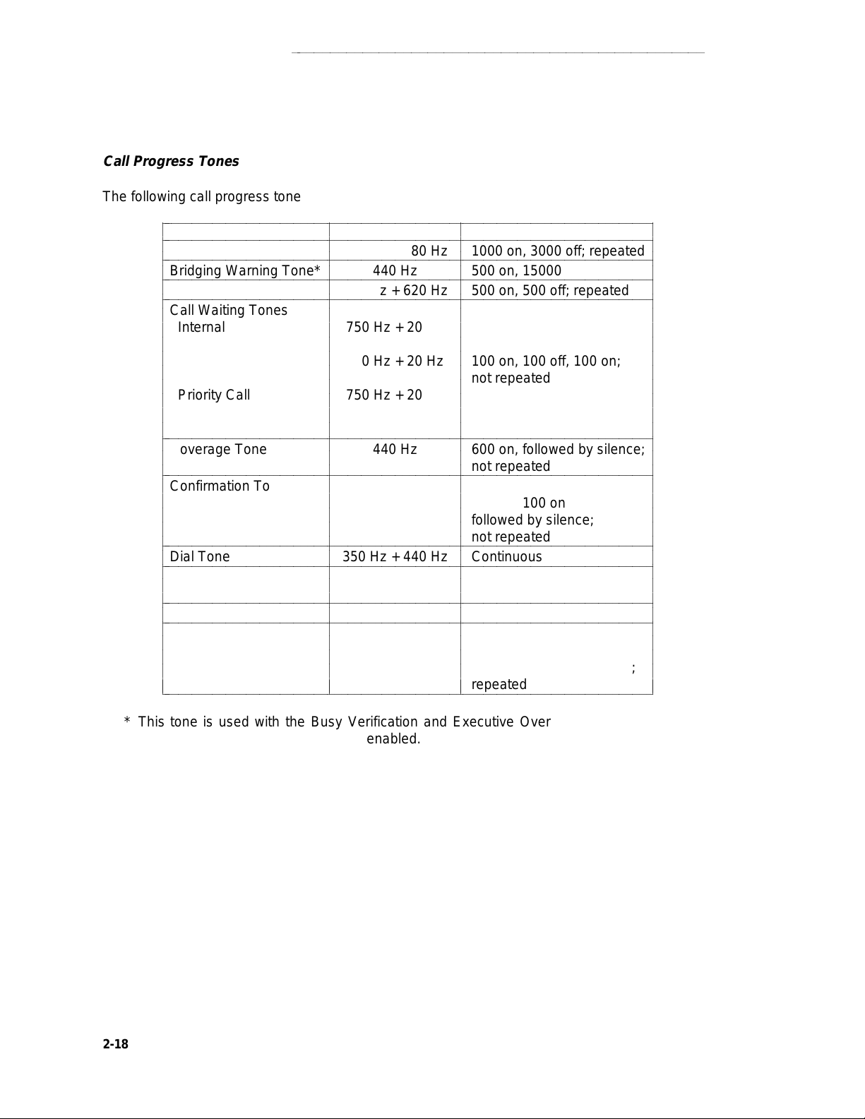
GENERAL INFORMATION
aaaaaaaaaaaaaaaaaaaaaaaaaaaaaaaaaaaaaaaaaaaaaaaaaaa
Call Progress Tones
The following call progress tones are generated by the system:
bbbbbbbbbbbbbbbbbbbbbbbbbbbbbbbbbbbbbbbbbbbbbbbbbbbbbbbbbbbbbbbbbbbbbbbbb
c
bbbbbbbbbbbbbbbbbbbbbbbbbbbbbbbbbbbbbbbbbbbbbbbbbbbbbbbbbbbbbbbbbbbbbbbbb
c
Ringback Tone 440 Hz + 480 Hz 1000 on, 3000 off; repeated
bbbbbbbbbbbbbbbbbbbbbbbbbbbbbbbbbbbbbbbbbbbbbbbbbbbbbbbbbbbbbbbbbbbbbbbbb
c
Bridging Warning Tone* 440 Hz 500 on, 15000 off; repeated
bbbbbbbbbbbbbbbbbbbbbbbbbbbbbbbbbbbbbbbbbbbbbbbbbbbbbbbbbbbbbbbbbbbbbbbbb
c
c
Busy Tone 480 Hz + 620 Hz 500 on, 500 off; repeated
bbbbbbbbbbbbbbbbbbbbbbbbbbbbbbbbbbbbbbbbbbbbbbbbbbbbbbbbbbbbbbbbbbbbbbbbb
c
Call Waiting Tones
c
Internal 750 Hz + 20 Hz 100 on; not repeated
c
External or Handled
c
c
by Attendant 750 Hz + 20 Hz 100 on, 100 off, 100 on;
c
c
Priority Call 750 Hz + 20 Hz 100 on, 100 off, 100 on,
c
c
c
bbbbbbbbbbbbbbbbbbbbbbbbbbbbbbbbbbbbbbbbbbbbbbbbbbbbbbbbbbbbbbbbbbbbbbbbb
c
Coverage Tone 440 Hz 600 on, followed by silence;
c
bbbbbbbbbbbbbbbbbbbbbbbbbbbbbbbbbbbbbbbbbbbbbbbbbbbbbbbbbbbbbbbbbbbbbbbbb
c
Confirmation Tone 350 Hz + 440 Hz 100 on, 100 off, 100 on,
c
c
c
c
bbbbbbbbbbbbbbbbbbbbbbbbbbbbbbbbbbbbbbbbbbbbbbbbbbbbbbbbbbbbbbbbbbbbbbbbb
c
Dial Tone 350 Hz + 440 Hz Continuous
c
bbbbbbbbbbbbbbbbbbbbbbbbbbbbbbbbbbbbbbbbbbbbbbbbbbbbbbbbbbbbbbbbbbbbbbbbb
c
Intercept Tone 480 Hz & 620 Hz 250 on (480 Hz),
c
bbbbbbbbbbbbbbbbbbbbbbbbbbbbbbbbbbbbbbbbbbbbbbbbbbbbbbbbbbbbbbbbbbbbbbbbb
c
Reorder Tone 480 Hz + 620 Hz 250 on, 250 off; repeated
c
bbbbbbbbbbbbbbbbbbbbbbbbbbbbbbbbbbbbbbbbbbbbbbbbbbbbbbbbbbbbbbbbbbbbbbbbb
c
Call Waiting
c
Ringback Tone 440 Hz + 480 Hz; 1000 on (440 Hz + 480 Hz),
c
c
c
bbbbbbbbbbbbbbbbbbbbbbbbbbbbbbbbbbbbbbbbbbbbbbbbbbbbbbbbbbbbbbbbbbbbbbbbbc
TONE FREQUENCY PATTERN (In ms)
c
c
c
c
c
c
c
c
c
c
c
c
c
c
c
c
c
c
c
c
c
c
c
c
c
c
c
c
c
c
c
c
c
c
440 Hz 200 on (440 Hz), 2800 off;
c
c
c
c
c
c
c
c
c
c
c
not repeated
c
c
100 off, 100 on;
c
not repeated
c
c
c
not repeated
c
c
c
100 off, 100 on
c
followed by silence;
c
not repeated
c
c
c
c
250 on (620 Hz); repeated
c
c
c
c
c
c
repeated
c
c
c
c
c
c
c
c
c
c
c
c
c
c
c
c
c
c
c
c
c
c
c
c
c
c
c
c
c
c
c
c
c
c
c
c
* This tone is used with the Busy Verification and Executive Override features and Service
Observing when the warning tone is enabled.
2-18
Page 59
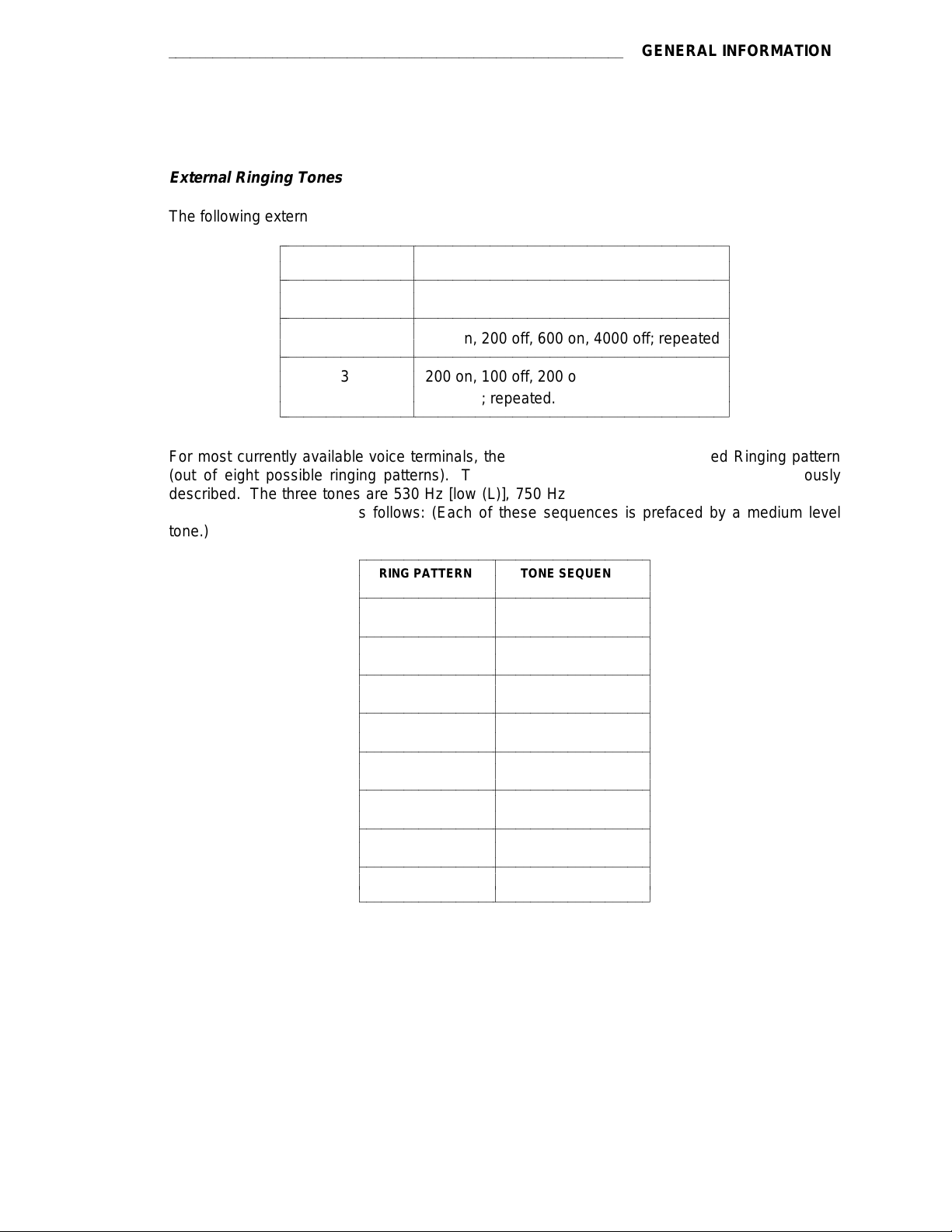
aaaaaaaaaaaaaaaaaaaaaaaaaaaaaaaaaaaaaaaaaaaaaaaaaaaaaaaaaaaaa
GENERAL INFORMATION
External Ringing Tones
The following external ringing tone patterns are generated by the system:
bbbbbbbbbbbbbbbbbbbbbbbbbbbbbbbbbbbbbbbbbbbbbbbbbbbbbbbbbbbbb
c
RINGING TONE PATTERN (In ms)
c
bbbbbbbbbbbbbbbbbbbbbbbbbbbbbbbbbbbbbbbbbbbbbbbbbbbbbbbbbbbbb
c
c
bbbbbbbbbbbbbbbbbbbbbbbbbbbbbbbbbbbbbbbbbbbbbbbbbbbbbbbbbbbbb
c
c
c
bbbbbbbbbbbbbbbbbbbbbbbbbbbbbbbbbbbbbbbbbbbbbbbbbbbbbbbbbbbbb
1 1200 on, 4000 off; repeated
2 400 on, 200 off, 600 on, 4000 off; repeated
c
c
3 200 on, 100 off, 200 on, 100 off, 600 on,
c
bbbbbbbbbbbbbbbbbbbbbbbbbbbbbbbbbbbbbbbbbbbbbbbbbbbbbbbbbbbbbc
c
c
c
c
c
c
c
c
c
c
4000 off; repeated.
c
c
c
c
c
c
c
c
c
c
c
c
For most currently available voice terminals, the user can select a Personalized Ringing pattern
(out of eight possible ringing patterns). The tone patterns are the same as those previously
described. The three tones are 530 Hz [low (L)], 750 Hz [medium (M)], and 1060 Hz [high (H)].
The tone sequences are as follows: (Each of these sequences is prefaced by a medium level
tone.)
bbbbbbbbbbbbbbbbbbbbbbbbbbbbbbbbbbbbbbb
c
RING PATTERN TONE SEQUENCE
c
bbbbbbbbbbbbbbbbbbbbbbbbbbbbbbbbbbbbbbb
c
c
bbbbbbbbbbbbbbbbbbbbbbbbbbbbbbbbbbbbbbb
c
c
c
bbbbbbbbbbbbbbbbbbbbbbbbbbbbbbbbbbbbbbb
c
c
bbbbbbbbbbbbbbbbbbbbbbbbbbbbbbbbbbbbbbb
c
c
c
bbbbbbbbbbbbbbbbbbbbbbbbbbbbbbbbbbbbbbb
c
c
bbbbbbbbbbbbbbbbbbbbbbbbbbbbbbbbbbbbbbb
c
c
c
bbbbbbbbbbbbbbbbbbbbbbbbbbbbbbbbbbbbbbb
1 MMM
2 HHH
3 LLL
4 LHH
5 HHL
6 HLL
c
c
bbbbbbbbbbbbbbbbbbbbbbbbbbbbbbbbbbbbbbb
c
c
bbbbbbbbbbbbbbbbbbbbbbbbbbbbbbbbbbbbbbbc
7 HLH
8 LHL
c
c
c
c
c
c
c
c
c
c
c
c
c
c
c
c
c
c
c
c
c
c
c
c
c
c
c
c
c
c
c
c
c
c
c
c
c
c
c
c
c
c
c
c
2-19
Page 60

GENERAL INFORMATION
aaaaaaaaaaaaaaaaaaaaaaaaaaaaaaaaaaaaaaaaaaaaaaaaaaa
Indicator Lights Signals
The following light signals are generated by the system for the attendant console and multiappearance voice terminals.
bbbbbbbbbbbbbbbbbbbbbbbbbbbbbbbbbbbbbbbbbbbbbbb
c
LAMP SIGNAL PATTERN (In ms)
bbbbbbbbbbbbbbbbbbbbbbbbbbbbbbbbbbbbbbbbbbbbbbb
c
c
Dark (Off) Off
c
bbbbbbbbbbbbbbbbbbbbbbbbbbbbbbbbbbbbbbbbbbbbbbb
c
c
Lighted (On) On
bbbbbbbbbbbbbbbbbbbbbbbbbbbbbbbbbbbbbbbbbbbbbbb
c
c
Flashing 500 on, 500 off; repeated
c
bbbbbbbbbbbbbbbbbbbbbbbbbbbbbbbbbbbbbbbbbbbbbbb
c
c
Fluttering 50 on, 50 off; repeated
bbbbbbbbbbbbbbbbbbbbbbbbbbbbbbbbbbbbbbbbbbbbbbb
c
c
Broken Flutter 5 cycles of 50 on, 50 off,
c
c
bbbbbbbbbbbbbbbbbbbbbbbbbbbbbbbbbbbbbbbbbbbbbbb
c
c
Wink 350 on, 50 off; repeated
c
bbbbbbbbbbbbbbbbbbbbbbbbbbbbbbbbbbbbbbbbbbbbbbbc
c
c
c
c
c
c
c
c
c
c
c
c
c
c
followed by 500 off; repeated
c
c
c
c
c
c
c
c
c
c
c
c
c
c
c
c
c
c
c
c
c
c
c
c
2-20
Page 61

aaaaaaaaaaaaaaaaaaaaaaaaaaaaaaaaaaaaaaaaaaaaaaaaaaaaaaaa
EXPOSED PORT PROTECTION
EXPOSED PORT PROTECTION
Requirements
All port packs and terminals require unique protection and grounding arrangements as defined in
the checklists (
555-200-120 and
555-103-120). These arrangements provide an adequate barrier to the potentially damaging voltages and currents inherent in lightning and power surges present in exposed applications.
Moreover, the National Electrical Code requires that an approved protector be provided on all
exposed circuits.
Exposed Ports And Terminals Defined
Ports and terminals that utilize facilities that are subject to disturbances from lightning, ground
potential rises (GPR), or possible contact or induction from electrical power sources or circuits in
excess of 300 volts (RMS) to ground are classified as exposed. Any ports or terminals served by
such exposed facilities are classified as exposed and require protection at both the port and terminal ends. The checklists contain flowcharts that are beneficial in determining exposure status
and tables to determine the type of protector required.
AT&T System 75 Electrical Protection, Grounding, and Exposure Checklist
AT&T System 85 Electrical Protection, Grounding, and Exposure Checklist
,
,
Out-of-Building Campus Stations
An out-of-building campus station is a telephone or voice terminal that is not physically located in
the same building as the equipment room, but is located on the same property. Both analog telephones and digital voice terminals can be used as out-of-building stations
Carbon block, or equivalent, protection is required at both building entrances for analog out-ofbuilding stations. Sneak current protection is also required. Protection can be provided by a
4-type protector or a 3-type protector plus a separate sneak current protector. The 4-type protector is equipped with a heat coil for sneak current protection. The 4-type primary protector is the
preferred device.
Protection is required at both entrances for digital out-of-building voice terminals. There are two
different types of protectors that can be used to protect digital voice terminals and digital line circuit packs in an out-of-building environment: the 4C3S-75 Enhanced Protector and the ITW Linx
Enhanced Protector.
Note: The 4C3S-75 Enhanced Protector may only be used on Vintage 14 or newer TN754
Circuit Packs. The 4C3S-75 can be used on all vintages of the TN754B Circuit
Pack. The ITW Linx Enhanced Protector may be used on all Vintages of the TN754
and TN754B Circuit Packs.
The 4C3S-75 Enhanced Protector is equipped with a heat coil for sneak current protection and
the ITW Linx Enhanced Protector is equipped with replaceable fuses for sneak current protection.
The maximum range for out-of-building voice terminals is 3,400 feet when using 24 AWG wire
2-21
Page 62
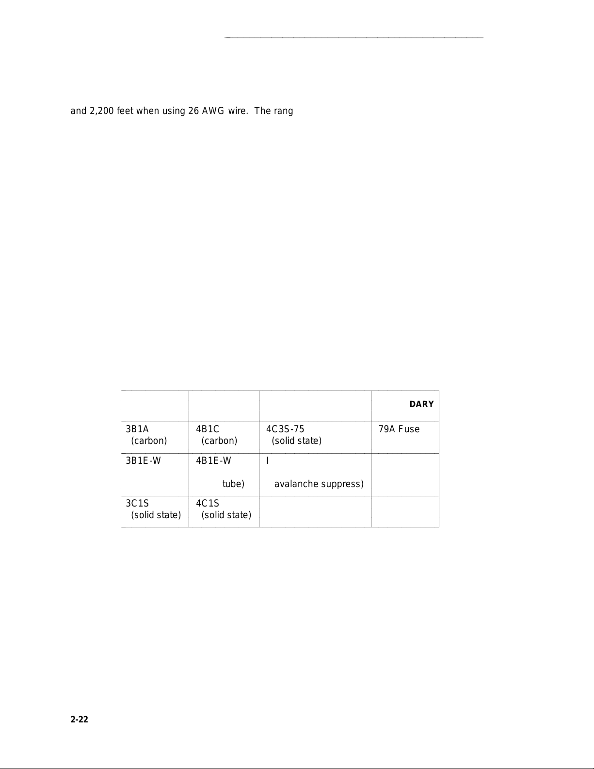
EXPOSED PORT PROTECTION
aaaaaaaaaaaaaaaaaaaaaaaaaaaaaaaaaaaaaaaaaaaaaaa
and 2,200 feet when using 26 AWG wire. The range can be extended to 5,000 feet (24 AWG) or
4,000 feet (24 AWG) with the use of a Data Link Protector (DLP). The DLP is an isolating
transformer used to remove phantom power on the switch side and reintroduce it on the terminal
side. When a DLP is used, the voice terminal must be locally powered by an external power supply or through the AC power cord provided with some of the 7400 series voice terminals. The
DLP is installed on the equipment side of the protection in both buildings. In high lightning areas,
the DLP may also be installed to provide the maximum degree of protection and reliability.
Table A shows the recommended protectors for the DEFINITY G1, G2, G3, System 75, and System 85. Table B shows the in-range, out-of-building (IROB) protection for DEFINITY line circuits
and terminals.
Caution: The following circuit pack and terminal arrangements are not allowed to be
installed in an exposed environment:
1. 7300 Series connected to the TN762B or ANN17 Circuit Pack
2. MET terminals connected to the TN735 Circuit Pack
3. Analog terminals connected to the TN746 Circuit Pack
TABLE 2-C. Recommended Protectors
bbbbbbbbbbbbbbbbbbbbbbbbbbbbbbbbbbbbbbbbbbbbbbbbbbbbbbbbbbbbbbbbbbbbb
c
PRIMARY
c
c
bbbbbbbbbbbbbbbbbbbbbbbbbbbbbbbbbbbbbbbbbbbbbbbbbbbbbbbbbbbbbbbbbbbbb
c
3B1A 4B1C 4C3S-75 79A Fuse
c
(carbon) (carbon) (solid state)
c
bbbbbbbbbbbbbbbbbbbbbbbbbbbbbbbbbbbbbbbbbbbbbbbbbbbbbbbbbbbbbbbbbbbbb
c
3B1E-W 4B1E-W ITW Linx SCP-1
c
(wide-gap (wide-gap (gas tube
c
gas tube) gas tube) avalanche suppress)
c
bbbbbbbbbbbbbbbbbbbbbbbbbbbbbbbbbbbbbbbbbbbbbbbbbbbbbbbbbbbbbbbbbbbbb
c
3C1S 4C1S
c
c
(solid state) (solid state)
bbbbbbbbbbbbbbbbbbbbbbbbbbbbbbbbbbbbbbbbbbbbbbbbbbbbbbbbbbbbbbbbbbbbbc
c
PRIMARY ENHANCED
c
(w/Heat Coil) PRIMARY
c
c
c
c
c
c
c
c
c
c
c
c
c
c
c
c
c
c
c
c
c
c
c
c
c
c
c
SECONDARY
c
c
c
c
c
c
c
c
c
c
c
c
c
c
c
c
c
c
c
c
c
c
c
c
c
c
c
2-22
Page 63
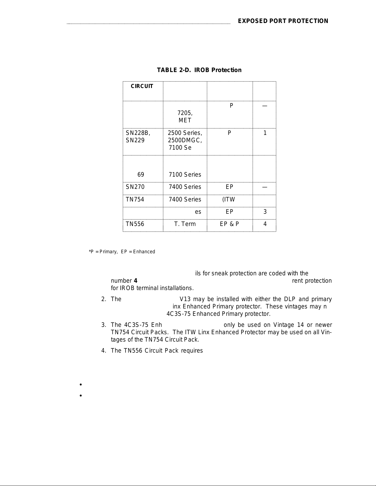
aaaaaaaaaaaaaaaaaaaaaaaaaaaaaaaaaaaaaaaaaaaaaaaaaaaaaaaa
TABLE 2-D. IROB Protection
bbbbbbbbbbbbbbbbbbbbbbbbbbbbbbbbbbbbbbbbbbbbbbbbbbbb
c
CIRCUIT REQUIRED SEE
c
PACKS
c
bbbbbbbbbbbbbbbbbbbbbbbbbbbbbbbbbbbbbbbbbbbbbbbbbbbb
c
SN224 7203, EP —
c
c
c
bbbbbbbbbbbbbbbbbbbbbbbbbbbbbbbbbbbbbbbbbbbbbbbbbbbb
c
SN228B, 2500 Series, P 1
c
SN229 2500DMGC,
c
c
bbbbbbbbbbbbbbbbbbbbbbbbbbbbbbbbbbbbbbbbbbbbbbbbbbbb
c
c
TN742, 500 Series, P 1
c
TN746B, 2500 Series,
c
TN769 7100 Series
c
bbbbbbbbbbbbbbbbbbbbbbbbbbbbbbbbbbbbbbbbbbbbbbbbbbbb
c
SN270 7400 Series EP —
c
bbbbbbbbbbbbbbbbbbbbbbbbbbbbbbbbbbbbbbbbbbbbbbbbbbbb
c
TN754 7400 Series (ITW) 2
c
bbbbbbbbbbbbbbbbbbbbbbbbbbbbbbbbbbbbbbbbbbbbbbbbbbbb
c
TN754, V14 7400 Series EP 3
c
bbbbbbbbbbbbbbbbbbbbbbbbbbbbbbbbbbbbbbbbbbbbbbbbbbbb
c
TN556 T. Term EP & P 4
c
bbbbbbbbbbbbbbbbbbbbbbbbbbbbbbbbbbbbbbbbbbbbbbbbbbbbc
c
TERMINAL
c
c
c
c
7205,
c
MET
c
c
c
c
c
7100 Series
c
c
c
c
c
c
c
c
c
c
c
c
c
c
c
c
PROTECTOR* NOTE
c
c
c
c
c
c
c
c
c
c
c
c
c
c
c
c
c
c
c
c
c
c
c
EXPOSED PORT PROTECTION
c
c
c
c
c
c
c
c
c
c
c
c
c
c
c
c
c
c
c
c
c
c
c
c
c
c
c
c
c
c
c
c
c
c
c
c
c
c
c
c
c
c
c
c
c
c
c
c
c
c
*P = Primary, EP = Enhanced Primary
Notes:
1. Primary protection with heat coils for sneak protection are coded with the
number 4 as the first numeric. DEFINITY ports require sneak current protection
for IROB terminal installations.
2. The TN754, V1 through V13 may be installed with either the DLP and primary
protector or the ITW Linx Enhanced Primary protector. These vintages may not
be installed with the 4C3S-75 Enhanced Primary protector.
3. The 4C3S-75 Enhanced Protector may only be used on Vintage 14 or newer
TN754 Circuit Packs. The ITW Linx Enhanced Protector may be used on all Vintages of the TN754 Circuit Pack.
4. The TN556 Circuit Pack requires Enhanced Primary protection at the port and
Primary (3- or 4-type) protection at the terminal.
For more information on exposed port protection, refer to:
d
DEFINITY Communications System Generic 1 and Generic 3 Wiring
d
DEFINITY Communications System Generic 2 and System 85 Wiring
, 555-204-111
, 555-104-630
2-23
Page 64

AVAILABILITY
aaaaaaaaaaaaaaaaaaaaaaaaaaaaaaaaaaaaaaaaaaaaaaaaaaaaaaaaaaaa
2-24
Page 65

aaaaaaaaaaaaaaaaaaaaaaaaaaaaaaaaaaaaaaaaaaaaaaaaaaaaaaaaaaaaaaaaaaaaaaaa
AVAILABILITY
AVAILABILITY
This section provides the availability of the products described in this manual. The availability of
these products is constantly changing as new products and different versions of existing products
are introduced. The status of some of the products in this list may have changed since this
manual was issued. Check the Sales Manual for the final determination of the equipment status.
The following convention is used in Table A:
d
DA—Discontinued Availability
d
GA—General Availability
d
LA—Limited Availability
2-25
Page 66
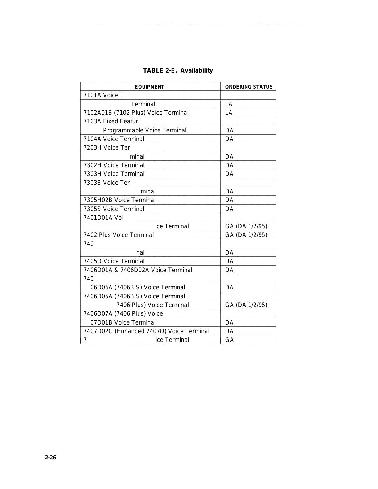
AVAILABILITY
bbbbbbbbbbbbbbbbbbbbbbbbbbbbbbbbbbbbbbbbbbbbbbbbbbbbbbbbbbbbbbbbbb
c
bbbbbbbbbbbbbbbbbbbbbbbbbbbbbbbbbbbbbbbbbbbbbbbbbbbbbbbbbbbbbbbbbb
c
bbbbbbbbbbbbbbbbbbbbbbbbbbbbbbbbbbbbbbbbbbbbbbbbbbbbbbbbbbbbbbbbbb
c
c
bbbbbbbbbbbbbbbbbbbbbbbbbbbbbbbbbbbbbbbbbbbbbbbbbbbbbbbbbbbbbbbbbb
c
bbbbbbbbbbbbbbbbbbbbbbbbbbbbbbbbbbbbbbbbbbbbbbbbbbbbbbbbbbbbbbbbbb
c
c
bbbbbbbbbbbbbbbbbbbbbbbbbbbbbbbbbbbbbbbbbbbbbbbbbbbbbbbbbbbbbbbbbb
c
bbbbbbbbbbbbbbbbbbbbbbbbbbbbbbbbbbbbbbbbbbbbbbbbbbbbbbbbbbbbbbbbbb
c
bbbbbbbbbbbbbbbbbbbbbbbbbbbbbbbbbbbbbbbbbbbbbbbbbbbbbbbbbbbbbbbbbb
c
c
bbbbbbbbbbbbbbbbbbbbbbbbbbbbbbbbbbbbbbbbbbbbbbbbbbbbbbbbbbbbbbbbbb
c
bbbbbbbbbbbbbbbbbbbbbbbbbbbbbbbbbbbbbbbbbbbbbbbbbbbbbbbbbbbbbbbbbb
c
c
bbbbbbbbbbbbbbbbbbbbbbbbbbbbbbbbbbbbbbbbbbbbbbbbbbbbbbbbbbbbbbbbbb
c
bbbbbbbbbbbbbbbbbbbbbbbbbbbbbbbbbbbbbbbbbbbbbbbbbbbbbbbbbbbbbbbbbb
c
bbbbbbbbbbbbbbbbbbbbbbbbbbbbbbbbbbbbbbbbbbbbbbbbbbbbbbbbbbbbbbbbbb
c
c
bbbbbbbbbbbbbbbbbbbbbbbbbbbbbbbbbbbbbbbbbbbbbbbbbbbbbbbbbbbbbbbbbb
c
bbbbbbbbbbbbbbbbbbbbbbbbbbbbbbbbbbbbbbbbbbbbbbbbbbbbbbbbbbbbbbbbbb
c
c
bbbbbbbbbbbbbbbbbbbbbbbbbbbbbbbbbbbbbbbbbbbbbbbbbbbbbbbbbbbbbbbbbb
c
bbbbbbbbbbbbbbbbbbbbbbbbbbbbbbbbbbbbbbbbbbbbbbbbbbbbbbbbbbbbbbbbbb
c
bbbbbbbbbbbbbbbbbbbbbbbbbbbbbbbbbbbbbbbbbbbbbbbbbbbbbbbbbbbbbbbbbb
c
c
bbbbbbbbbbbbbbbbbbbbbbbbbbbbbbbbbbbbbbbbbbbbbbbbbbbbbbbbbbbbbbbbbb
c
bbbbbbbbbbbbbbbbbbbbbbbbbbbbbbbbbbbbbbbbbbbbbbbbbbbbbbbbbbbbbbbbbb
c
c
bbbbbbbbbbbbbbbbbbbbbbbbbbbbbbbbbbbbbbbbbbbbbbbbbbbbbbbbbbbbbbbbbb
c
bbbbbbbbbbbbbbbbbbbbbbbbbbbbbbbbbbbbbbbbbbbbbbbbbbbbbbbbbbbbbbbbbb
c
bbbbbbbbbbbbbbbbbbbbbbbbbbbbbbbbbbbbbbbbbbbbbbbbbbbbbbbbbbbbbbbbbb
c
c
bbbbbbbbbbbbbbbbbbbbbbbbbbbbbbbbbbbbbbbbbbbbbbbbbbbbbbbbbbbbbbbbbb
c
bbbbbbbbbbbbbbbbbbbbbbbbbbbbbbbbbbbbbbbbbbbbbbbbbbbbbbbbbbbbbbbbbb
c
c
bbbbbbbbbbbbbbbbbbbbbbbbbbbbbbbbbbbbbbbbbbbbbbbbbbbbbbbbbbbbbbbbbb
c
bbbbbbbbbbbbbbbbbbbbbbbbbbbbbbbbbbbbbbbbbbbbbbbbbbbbbbbbbbbbbbbbbb
c
bbbbbbbbbbbbbbbbbbbbbbbbbbbbbbbbbbbbbbbbbbbbbbbbbbbbbbbbbbbbbbbbbb
c
c
bbbbbbbbbbbbbbbbbbbbbbbbbbbbbbbbbbbbbbbbbbbbbbbbbbbbbbbbbbbbbbbbbb
c
bbbbbbbbbbbbbbbbbbbbbbbbbbbbbbbbbbbbbbbbbbbbbbbbbbbbbbbbbbbbbbbbbb
c
c
bbbbbbbbbbbbbbbbbbbbbbbbbbbbbbbbbbbbbbbbbbbbbbbbbbbbbbbbbbbbbbbbbbc
aaaaaaaaaaaaaaaaaaaaaaaaaaaaaaaaaaaaaaaaaaaaaaaaaaaaaaaaaaaa
TABLE 2-E. Availability
EQUIPMENT ORDERING STATUS
7101A Voice Terminal DA
7102A01A Voice Terminal LA
7102A01B (7102 Plus) Voice Terminal LA
7103A Fixed Feature Voice Terminal DA
7103A Programmable Voice Terminal DA
7104A Voice Terminal DA
7203H Voice Terminal DA
7205H Voice Terminal DA
7302H Voice Terminal DA
7303H Voice Terminal DA
7303S Voice Terminal DA
7305H01B Voice Terminal DA
7305H02B Voice Terminal DA
7305S Voice Terminal DA
7401D01A Voice Terminal DA
7401D02A (7401 Plus) Voice Terminal GA (DA 1/2/95)
7402 Plus Voice Terminal GA (DA 1/2/95)
7403D Voice Terminal DA
7404D Voice Terminal DA
7405D Voice Terminal DA
7406D01A & 7406D02A Voice Terminal DA
7406D03A & 7406D04A Voice Terminal DA
7406D06A (7406BIS) Voice Terminal DA
7406D05A (7406BIS) Voice Terminal w/display DA
7406D08A (7406 Plus) Voice Terminal GA (DA 1/2/95)
7406D07A (7406 Plus) Voice Terminal w/display GA
7407D01B Voice Terminal DA
7407D02C (Enhanced 7407D) Voice Terminal DA
7407D02D (7407 Plus) Voice Terminal GA
c
c
c
c
c
c
c
c
c
c
c
c
c
c
c
c
c
c
c
c
c
c
c
c
c
c
c
c
c
c
c
c
c
c
c
c
c
c
c
c
c
c
c
c
c
c
c
c
c
c
c
c
c
c
c
c
c
c
c
c
c
c
c
c
c
c
c
c
c
c
c
c
c
c
c
c
c
c
c
c
c
c
c
c
c
c
2-26
Page 67
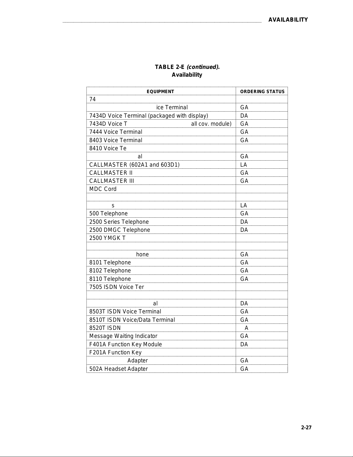
aaaaaaaaaaaaaaaaaaaaaaaaaaaaaaaaaaaaaaaaaaaaaaaaaaaaaaaaaaaaaaaaaaaaaaaa
AVAILABILITY
TABLE 2-E
(continued).
Availability
bbbbbbbbbbbbbbbbbbbbbbbbbbbbbbbbbbbbbbbbbbbbbbbbbbbbbbbbbbbbbbbbbbbbbbbbb
c
bbbbbbbbbbbbbbbbbbbbbbbbbbbbbbbbbbbbbbbbbbbbbbbbbbbbbbbbbbbbbbbbbbbbbbbbb
c
7410D01A Voice Terminal DA
bbbbbbbbbbbbbbbbbbbbbbbbbbbbbbbbbbbbbbbbbbbbbbbbbbbbbbbbbbbbbbbbbbbbbbbbb
c
7410D02A (7410 Plus) Voice Terminal GA
c
bbbbbbbbbbbbbbbbbbbbbbbbbbbbbbbbbbbbbbbbbbbbbbbbbbbbbbbbbbbbbbbbbbbbbbbbb
c
7434D Voice Terminal (packaged with display) DA
bbbbbbbbbbbbbbbbbbbbbbbbbbbbbbbbbbbbbbbbbbbbbbbbbbbbbbbbbbbbbbbbbbbbbbbbb
c
7434D Voice Terminal (packaged with call cov. module) GA
c
bbbbbbbbbbbbbbbbbbbbbbbbbbbbbbbbbbbbbbbbbbbbbbbbbbbbbbbbbbbbbbbbbbbbbbbbb
c
7444 Voice Terminal GA
bbbbbbbbbbbbbbbbbbbbbbbbbbbbbbbbbbbbbbbbbbbbbbbbbbbbbbbbbbbbbbbbbbbbbbbbb
c
8403 Voice Terminal GA
bbbbbbbbbbbbbbbbbbbbbbbbbbbbbbbbbbbbbbbbbbbbbbbbbbbbbbbbbbbbbbbbbbbbbbbbb
c
c
8410 Voice Terminal GA
bbbbbbbbbbbbbbbbbbbbbbbbbbbbbbbbbbbbbbbbbbbbbbbbbbbbbbbbbbbbbbbbbbbbbbbbb
c
8434 Voice Terminal GA
bbbbbbbbbbbbbbbbbbbbbbbbbbbbbbbbbbbbbbbbbbbbbbbbbbbbbbbbbbbbbbbbbbbbbbbbb
c
CALLMASTER (602A1 and 603D1) LA
c
bbbbbbbbbbbbbbbbbbbbbbbbbbbbbbbbbbbbbbbbbbbbbbbbbbbbbbbbbbbbbbbbbbbbbbbbb
c
CALLMASTER II GA
bbbbbbbbbbbbbbbbbbbbbbbbbbbbbbbbbbbbbbbbbbbbbbbbbbbbbbbbbbbbbbbbbbbbbbbbb
c
CALLMASTER III GA
bbbbbbbbbbbbbbbbbbbbbbbbbbbbbbbbbbbbbbbbbbbbbbbbbbbbbbbbbbbbbbbbbbbbbbbbb
c
c
MDC Cordless 9000 GA
bbbbbbbbbbbbbbbbbbbbbbbbbbbbbbbbbbbbbbbbbbbbbbbbbbbbbbbbbbbbbbbbbbbbbbbbb
c
MDW Wireless 9000 GA
bbbbbbbbbbbbbbbbbbbbbbbbbbbbbbbbbbbbbbbbbbbbbbbbbbbbbbbbbbbbbbbbbbbbbbbbb
c
MET Sets LA
c
bbbbbbbbbbbbbbbbbbbbbbbbbbbbbbbbbbbbbbbbbbbbbbbbbbbbbbbbbbbbbbbbbbbbbbbbb
c
500 Telephone GA
bbbbbbbbbbbbbbbbbbbbbbbbbbbbbbbbbbbbbbbbbbbbbbbbbbbbbbbbbbbbbbbbbbbbbbbbb
c
2500 Series Telephone DA
bbbbbbbbbbbbbbbbbbbbbbbbbbbbbbbbbbbbbbbbbbbbbbbbbbbbbbbbbbbbbbbbbbbbbbbbb
c
c
2500 DMGC Telephone DA
bbbbbbbbbbbbbbbbbbbbbbbbbbbbbbbbbbbbbbbbbbbbbbbbbbbbbbbbbbbbbbbbbbbbbbbbb
c
2500 YMGK Telephone GA
bbbbbbbbbbbbbbbbbbbbbbbbbbbbbbbbbbbbbbbbbbbbbbbbbbbbbbbbbbbbbbbbbbbbbbbbb
c
2500 MMGL Telephone GA
c
bbbbbbbbbbbbbbbbbbbbbbbbbbbbbbbbbbbbbbbbbbbbbbbbbbbbbbbbbbbbbbbbbbbbbbbbb
c
2500 YMGL Telephone GA
bbbbbbbbbbbbbbbbbbbbbbbbbbbbbbbbbbbbbbbbbbbbbbbbbbbbbbbbbbbbbbbbbbbbbbbbb
c
8101 Telephone GA
bbbbbbbbbbbbbbbbbbbbbbbbbbbbbbbbbbbbbbbbbbbbbbbbbbbbbbbbbbbbbbbbbbbbbbbbb
c
c
8102 Telephone GA
bbbbbbbbbbbbbbbbbbbbbbbbbbbbbbbbbbbbbbbbbbbbbbbbbbbbbbbbbbbbbbbbbbbbbbbbb
c
8110 Telephone GA
bbbbbbbbbbbbbbbbbbbbbbbbbbbbbbbbbbbbbbbbbbbbbbbbbbbbbbbbbbbbbbbbbbbbbbbbb
c
7505 ISDN Voice Terminal DA
c
bbbbbbbbbbbbbbbbbbbbbbbbbbbbbbbbbbbbbbbbbbbbbbbbbbbbbbbbbbbbbbbbbbbbbbbbb
c
7506 ISDN Voice Terminal DA
bbbbbbbbbbbbbbbbbbbbbbbbbbbbbbbbbbbbbbbbbbbbbbbbbbbbbbbbbbbbbbbbbbbbbbbbb
c
7507 ISDN Voice Terminal DA
bbbbbbbbbbbbbbbbbbbbbbbbbbbbbbbbbbbbbbbbbbbbbbbbbbbbbbbbbbbbbbbbbbbbbbbbb
c
c
8503T ISDN Voice Terminal GA
bbbbbbbbbbbbbbbbbbbbbbbbbbbbbbbbbbbbbbbbbbbbbbbbbbbbbbbbbbbbbbbbbbbbbbbbb
c
8510T ISDN Voice/Data Terminal GA
bbbbbbbbbbbbbbbbbbbbbbbbbbbbbbbbbbbbbbbbbbbbbbbbbbbbbbbbbbbbbbbbbbbbbbbbb
c
8520T ISDN Voice/Data Terminal GA
c
bbbbbbbbbbbbbbbbbbbbbbbbbbbbbbbbbbbbbbbbbbbbbbbbbbbbbbbbbbbbbbbbbbbbbbbbb
c
Message Waiting Indicator GA
bbbbbbbbbbbbbbbbbbbbbbbbbbbbbbbbbbbbbbbbbbbbbbbbbbbbbbbbbbbbbbbbbbbbbbbbb
c
F401A Function Key Module DA
bbbbbbbbbbbbbbbbbbbbbbbbbbbbbbbbbbbbbbbbbbbbbbbbbbbbbbbbbbbbbbbbbbbbbbbbb
c
c
F201A Function Key Module DA
bbbbbbbbbbbbbbbbbbbbbbbbbbbbbbbbbbbbbbbbbbbbbbbbbbbbbbbbbbbbbbbbbbbbbbbbb
c
500A Headset Adapter GA
bbbbbbbbbbbbbbbbbbbbbbbbbbbbbbbbbbbbbbbbbbbbbbbbbbbbbbbbbbbbbbbbbbbbbbbbb
c
502A Headset Adapter GA
c
bbbbbbbbbbbbbbbbbbbbbbbbbbbbbbbbbbbbbbbbbbbbbbbbbbbbbbbbbbbbbbbbbbbbbbbbbc
EQUIPMENT ORDERING STATUS
c
c
c
c
c
c
c
c
c
c
c
c
c
c
c
c
c
c
c
c
c
c
c
c
c
c
c
c
c
c
c
c
c
c
c
c
c
c
c
c
c
c
c
c
c
c
c
c
c
c
c
c
c
c
c
c
c
c
c
c
c
c
c
c
c
c
c
c
c
c
c
c
c
c
c
c
c
c
c
c
c
c
c
c
c
c
c
c
c
c
c
c
c
c
c
c
c
c
c
c
2-27
Page 68

AVAILABILITY
aaaaaaaaaaaaaaaaaaaaaaaaaaaaaaaaaaaaaaaaaaaaaaaaaaaaaaaaaaaa
TABLE 2-E
(continued).
Availability
bbbbbbbbbbbbbbbbbbbbbbbbbbbbbbbbbbbbbbbbbbbbbbbbbbbbbbbb
c
bbbbbbbbbbbbbbbbbbbbbbbbbbbbbbbbbbbbbbbbbbbbbbbbbbbbbbbb
c
D401A Digital Display Module GA
bbbbbbbbbbbbbbbbbbbbbbbbbbbbbbbbbbbbbbbbbbbbbbbbbbbbbbbb
c
D401B Digital Display Module GA
c
bbbbbbbbbbbbbbbbbbbbbbbbbbbbbbbbbbbbbbbbbbbbbbbbbbbbbbbb
c
C401A Call Coverage Module DA
bbbbbbbbbbbbbbbbbbbbbbbbbbbbbbbbbbbbbbbbbbbbbbbbbbbbbbbb
c
C401B Call Coverage Module GA
c
bbbbbbbbbbbbbbbbbbbbbbbbbbbbbbbbbbbbbbbbbbbbbbbbbbbbbbbb
c
C201A Call Coverage Module DA
bbbbbbbbbbbbbbbbbbbbbbbbbbbbbbbbbbbbbbbbbbbbbbbbbbbbbbbb
c
4A Speakerphone DA
bbbbbbbbbbbbbbbbbbbbbbbbbbbbbbbbbbbbbbbbbbbbbbbbbbbbbbbb
c
c
S101A Speakerphone DA
bbbbbbbbbbbbbbbbbbbbbbbbbbbbbbbbbbbbbbbbbbbbbbbbbbbbbbbb
c
S102A Speakerphone DA
bbbbbbbbbbbbbbbbbbbbbbbbbbbbbbbbbbbbbbbbbbbbbbbbbbbbbbbb
c
S201A Speakerphone GA
c
bbbbbbbbbbbbbbbbbbbbbbbbbbbbbbbbbbbbbbbbbbbbbbbbbbbbbbbb
c
S202A Speakerphone GA
bbbbbbbbbbbbbbbbbbbbbbbbbbbbbbbbbbbbbbbbbbbbbbbbbbbbbbbb
c
S203A Speakerphone GA
bbbbbbbbbbbbbbbbbbbbbbbbbbbbbbbbbbbbbbbbbbbbbbbbbbbbbbbb
c
c
Message Cartridge DA
bbbbbbbbbbbbbbbbbbbbbbbbbbbbbbbbbbbbbbbbbbbbbbbbbbbbbbbb
c
2870A1 Automatic Dialer GA
bbbbbbbbbbbbbbbbbbbbbbbbbbbbbbbbbbbbbbbbbbbbbbbbbbbbbbbb
c
107 Loudspeaker DA
c
bbbbbbbbbbbbbbbbbbbbbbbbbbbbbbbbbbbbbbbbbbbbbbbbbbbbbbbb
c
7500B Data Module LA
bbbbbbbbbbbbbbbbbbbbbbbbbbbbbbbbbbbbbbbbbbbbbbbbbbbbbbbb
c
2500 Data Service Unit GA
bbbbbbbbbbbbbbbbbbbbbbbbbbbbbbbbbbbbbbbbbbbbbbbbbbbbbbbb
c
c
105A Isolating Data Interface GA
bbbbbbbbbbbbbbbbbbbbbbbbbbbbbbbbbbbbbbbbbbbbbbbbbbbbbbbb
c
48250 Local Distribution Service Unit GA
bbbbbbbbbbbbbbbbbbbbbbbbbbbbbbbbbbbbbbbbbbbbbbbbbbbbbbbb
c
Multiple Asynchronous Data Unit GA
c
bbbbbbbbbbbbbbbbbbbbbbbbbbbbbbbbbbbbbbbbbbbbbbbbbbbbbbbb
c
Asynchronous Data Module GA
bbbbbbbbbbbbbbbbbbbbbbbbbbbbbbbbbbbbbbbbbbbbbbbbbbbbbbbb
c
3270A Data Module DA
bbbbbbbbbbbbbbbbbbbbbbbbbbbbbbbbbbbbbbbbbbbbbbbbbbbbbbbb
c
c
3270C Data Module GA
bbbbbbbbbbbbbbbbbbbbbbbbbbbbbbbbbbbbbbbbbbbbbbbbbbbbbbbb
c
3270T Data Module DA
bbbbbbbbbbbbbbbbbbbbbbbbbbbbbbbbbbbbbbbbbbbbbbbbbbbbbbbb
c
Trunk Data Module DA
c
bbbbbbbbbbbbbbbbbbbbbbbbbbbbbbbbbbbbbbbbbbbbbbbbbbbbbbbb
c
Processor Data Module DA
bbbbbbbbbbbbbbbbbbbbbbbbbbbbbbbbbbbbbbbbbbbbbbbbbbbbbbbb
c
Modular Trunk Data Module GA
bbbbbbbbbbbbbbbbbbbbbbbbbbbbbbbbbbbbbbbbbbbbbbbbbbbbbbbb
c
c
Modular Processor Data Module GA
bbbbbbbbbbbbbbbbbbbbbbbbbbbbbbbbbbbbbbbbbbbbbbbbbbbbbbbb
c
703A Data Service Unit DA
bbbbbbbbbbbbbbbbbbbbbbbbbbbbbbbbbbbbbbbbbbbbbbbbbbbbbbbb
c
Z702AL1 Data Service Unit DA
c
bbbbbbbbbbbbbbbbbbbbbbbbbbbbbbbbbbbbbbbbbbbbbbbbbbbbbbbbc
EQUIPMENT ORDERING STATUS
c
c
c
c
c
c
c
c
c
c
c
c
c
c
c
c
c
c
c
c
c
c
c
c
c
c
c
c
c
c
c
c
c
c
c
c
c
c
c
c
c
c
c
c
c
c
c
c
c
c
c
c
c
c
c
c
c
c
c
c
c
c
c
c
c
c
c
c
c
c
c
c
c
c
c
c
c
c
c
c
c
c
c
c
c
c
2-28
Page 69

aaaaaaaaaaaaaaaaaaaaaaaaaaaaaaaaaaaaaaaaaaaaaaaaaaaaaaaaaaaaaaaaaaaaaaaa
AVAILABILITY
TABLE 2-E
(continued).
Availability
bbbbbbbbbbbbbbbbbbbbbbbbbbbbbbbbbbbbbbbbbbbbbbbbb
c
bbbbbbbbbbbbbbbbbbbbbbbbbbbbbbbbbbbbbbbbbbbbbbbbb
c
DEFINITY High Speed Link GA
bbbbbbbbbbbbbbbbbbbbbbbbbbbbbbbbbbbbbbbbbbbbbbbbb
c
Digital Terminal Data Module DA
c
bbbbbbbbbbbbbbbbbbbbbbbbbbbbbbbbbbbbbbbbbbbbbbbbb
c
7400A Data Module GA
bbbbbbbbbbbbbbbbbbbbbbbbbbbbbbbbbbbbbbbbbbbbbbbbb
c
7400B Data Module DA
c
bbbbbbbbbbbbbbbbbbbbbbbbbbbbbbbbbbbbbbbbbbbbbbbbb
c
7400B Plus Data Module GA
bbbbbbbbbbbbbbbbbbbbbbbbbbbbbbbbbbbbbbbbbbbbbbbbb
c
PC/PBX Platform GA
bbbbbbbbbbbbbbbbbbbbbbbbbbbbbbbbbbbbbbbbbbbbbbbbb
c
c
PC/ISDN Platform GA
bbbbbbbbbbbbbbbbbbbbbbbbbbbbbbbbbbbbbbbbbbbbbbbbb
c
PC/PBX Connection DA
bbbbbbbbbbbbbbbbbbbbbbbbbbbbbbbbbbbbbbbbbbbbbbbbb
c
E78 Plus/ISDN DA
c
bbbbbbbbbbbbbbbbbbbbbbbbbbbbbbbbbbbbbbbbbbbbbbbbb
c
PC/ISDN Interface Software
c
Developer’s Guide
bbbbbbbbbbbbbbbbbbbbbbbbbbbbbbbbbbbbbbbbbbbbbbbbbc
EQUIPMENT ORDERING STATUS
c
c
c
c
c
c
c
c
c
c
c
c
c
c
c
GA
c
c
c
c
c
c
c
c
c
c
c
c
c
c
c
c
c
c
c
2-29
Page 70

ADJUNCT POWER
aaaaaaaaaaaaaaaaaaaaaaaaaaaaaaaaaaaaaaaaaaaaaaaaaaaaaaaaa
2-30
Page 71

aaaaaaaaaaaaaaaaaaaaaaaaaaaaaaaaaaaaaaaaaaaaaaaaaaaaaaaaaaaaaaaaaaaa
ADJUNCT POWER
ADJUNCT POWER
Power for several of the adjuncts must be provided locally at the voice terminal or from a satellite
closet through the terminal wiring. The following power supplies are currently recommended:
d
The MSP-1 (WP92464L1) Power Supply—replaces the KS-22911 L1/2, 329A, and 353A
DC power supplies and the 2012D AC transformer. The MSP-1 can be used to supply
local power to ISDN-T 65xx, 75xx, and 85xx series voice terminals connected to an
AT&T DEFINITY Communications System and to the DCP 7444 and 8434 voice terminals which need auxiliary power for their vacuum fluorescent displays. The MSP-1 can
also supply auxiliary power to adjunct equipment such as the S201A and CS201A speakerphones or a 500A Headset Adapter attached to any currently manufactured analog,
DCP, or ISDN-T voice terminal equipped with an Adjunct jack. For more information on
the MSP-1 power supply, see the short section with connection diagrams later in this
section.
d
The ISDN 1145B1 Bulk Power Unit, 1146B Power Distribution Unit, and the 2.5/5.0 A.H.
back-up batteries provide an uninterruptible power source for ISDN telephones and terminals, NT1s, terminal adjuncts, and other customer premises equipment. During AC
power interruptions, batteries are automatically switched on to provide continuous power
to the load.
The distribution of power to the terminal equipment is provided by the 1146B distribution
unit. The 1146B provides 32 standard 110 connections to the load with overcurrent protection and alarm lights. The 1145B1/1146B power arrangement is compact (measuring
only 6.5 inches deep), lightweight, plastic enclosed, and designed for easy wall- or rackmounting.
During normal operation, the power supply/charger provides DC power to the load via the
distribution unit while maintaining the battery in a fully charged condition. The power system continuously monitors systems conditions with the status displayed on the front
panel of the power supply and distribution unit.
The following power supplies and transformers are NO LONGER recommended. They have
been replaced by the MSP-1 power supply and the 1145B1 bulk power unit described above.
d
2012D AC transformer— can be used locally or in a satellite closet to power a single 18
volt headset adapter or speakerphone.
d
KS-22911, L2 DC power supply—can be used locally or in a satellite closet to power a
headset adapter or speakerphone plus one additional adjunct. This unit has a 48 volt
power output of 10 watts.
d
KS-21239, L4, L5 AC transformer—can be used locally or in a satellite closet to power a
single 24 volt speakerphone-dialer.
d
PS3081096 AC transformer—can be used locally or in a satellite closet to power the
24 V S201A or S203A speakerphones.
d
329A DC power supply—can be used locally or in a satellite closet and is capable of supplying power to any number of adjuncts that may be added to a digital voice terminal.
This unit has a power output of 25 watts.
2-31
Page 72

ADJUNCT POWER
d
346A modular bulk DC power supply—can be used in a satellite closet only and is capable of supplying power to any number of adjuncts that may be added to a digital voice
terminal. This unit provides switch-selectable options for four outputs at 10 watts or two
outputs at 20 watts.
d
85B1-49 power unit—can be used locally or in a satellite closet to power the 4A speakerphone.
d
95B1 power unit—can be used locally or in a satellite closet to power a 2870A1
automatic dialer.
d
353 DC Power Supply—can be used locally only. It is designed to supply power to
ISDN-BRI stations and their adjuncts. It has a power output of 12 watts.
d
945 Bulk DC Power Supply—can be used in a satellite closet only. It is designed to
power ISDN-BRI stations and their adjuncts. It can optionally be equipped with a battery
to provide terminal operation for a limited time in case of an AC power failure. Up to 26
ISDN-BRI terminals can be supported by the 945 power supply.
aaaaaaaaaaaaaaaaaaaaaaaaaaaaaaaaaaaaaaaaaaaaaaaaaaaaaaaaa
2-32
Page 73

aaaaaaaaaaaaaaaaaaaaaaaaaaaaaaaaaaaaaaaaaaaaaaaaaaaaaaaaaaaaaaaaaaaa
ADJUNCT POWER
Information on the Older Power Supplies
The following diagram shows the connections with the older power supplies.
Note: The MSP-1 replaces the KS-22911 L1/2, 329A, and 353A DC power supplies and
the 2012D AC transformer.
FIGURE 2-4. Local and Satellite Power Sources for Voice Terminals Adjuncts
2-33
Page 74

ADJUNCT POWER
aaaaaaaaaaaaaaaaaaaaaaaaaaaaaaaaaaaaaaaaaaaaaaaaaaaaaaaaa
One of these power supplies must be used for each voice terminal equipped with one or more
adjuncts. Each of these power supplies (except the 95B1) has a maximum cable distance of
250 feet (76 m) between the power supply and the adjunct(s). The maximum cable distance for
the 95B1 is 150 feet (45m). Voice terminal adjuncts and modules are not operational during
interruptions of commercial AC power unless their power supplies are also powered through
standby power of other essential AC power service.
The 329A and 346A power supplies clustered in a satellite closet are normally mounted on AC
power strips. Power to these strips is provided from a dedicated 120 volt AC, 60-Hz, 20-ampere
circuit breaker and feeder either directly or through a 543A telephone power unit. The 543A unit
provides an inductive filter to limit inrush current on the feeder. It comes equipped with an AC
power cord which plugs into the dedicated feeder and provides four receptacles for AC power
strips.
The 945 bulk power system is usually rack mounted and is intended to be located in an equipment room or satellite closet. It is optionally made up of the following components:
d
945-1 bulk power supply unit
d
945-2 battery reserve unit
d
945-3 system enclosure, equipped with one or two 945-1 and/or a 945-2
d
945-4 single enclosure for 945-1 unit
Several power supplies and connection schemes are available for providing auxiliary adjunct
power when it is required. Regardless of its source, auxiliary power is introduced into a pair of
spare leads in the individual voice terminal’s line, at some wiring interface. The auxiliary power is
fed into the terminal on the mounting line cord. From the terminal, power is distributed to the
adjunct(s). An auxiliary power source is usually mounted in a satellite closet or adjacent to the
voice terminal’s wall jack.
2-34
Page 75

aaaaaaaaaaaaaaaaaaaaaaaaaaaaaaaaaaaaaaaaaaaaaaaaaaaaaaaaaaaaaaaaaaaa
ADJUNCT POWER
The MSP-1 Power Supply
The MSP-1 (WP92464L1) Power Supply can be used to supply local power to ISDN-T 65xx,
75xx, and 85xx series voice terminals connected to an AT&T DEFINITY Communications System
and to the DCP 7444 and 8434 voice terminals which need auxiliary power for their vacuum
fluorescent displays. The MSP-1 can also supply auxiliary power to adjunct equipment such as
the S201A and CS201A speakerphones or a 500A Headset Adapter attached to any currently
manufactured analog, DCP, or ISDN-T voice terminal equipped with an Adjunct jack.
CAUTION: The MSP-1 Power Supply can be used
only
with telecommunications equipment,
indoors, in a controlled environment.
NOTES:
One power supply will support one telephone with or without an adjunct.
The maximum loop range between the telephone and the power supply is
250 feet.
This power supply replaces the KS-22911-L1/2, 329A, and
353A DC Power Supplies and the 2012D AC Transformer.
The MSP-1 power supply has a single output of -48 volt DC, 0.4 amperes, and can operate from
either a 120 VAC 60 Hz power source (105 to 129 VAC) or a 220/230/240 50 Hz power source
(198 to 264 VAC). Input voltage selection is automatic; that is, the power supply adjusts itself for
the type of input voltage. The output capacity is 19.2 watts.
Contents of the MSP-1 Package (and Comcodes)
The MSP-1 package includes the following items: (Comcodes are provided for additional orders)
d
One MSP-1 power supply (Comcode: 406743419)
d
One 6-foot, 7-inch input power cord (Comcode: 403271117)
d
One 7-foot D8W cord (Comcode: 103786786)
d
Double-sided adhesive fastener strips for mounting the power supply on a flat vertical
surface (Comcode: 406824789)
d
These printed instructions.
2-35
Page 76

ADJUNCT POWER
aaaaaaaaaaaaaaaaaaaaaaaaaaaaaaaaaaaaaaaaaaaaaaaaaaaaaaaaa
Connecting the Power Supply
The power output is provided through 3 modular jacks on the power supply. These jacks are
labeled, from left to right,
PHONE OTHER LINE
-7 +8 -2 +5
The - and + numbers under ‘‘PHONE’’ and ‘‘OTHER’’ refer to the pins on which power is present
and the polarity of that power.
The PHONE and LINE jacks are 8-pin female non-keyed 657-type jacks that can accept D4, D6,
and D8 modular plug cables. The OTHER jack is a 6-pin female non-keyed 657-type jack.
The following local powering arrangements, shown in Figures 1 and 2, can be used with the
MSP-1 power supply.
d
Figure 1 shows the local powering arrangement for: ISDN voice terminals; the DCP 7444
and 8434 voice terminals’ VF displays; and adjuncts connected to all telephones except
the 8102.
d
Figure 2 shows the local powering arrangement for adjuncts connected to the 8102 telephone.
Note: The type of cord(s) needed to make these connections are designated in each draw-
ing.
2-36
Page 77
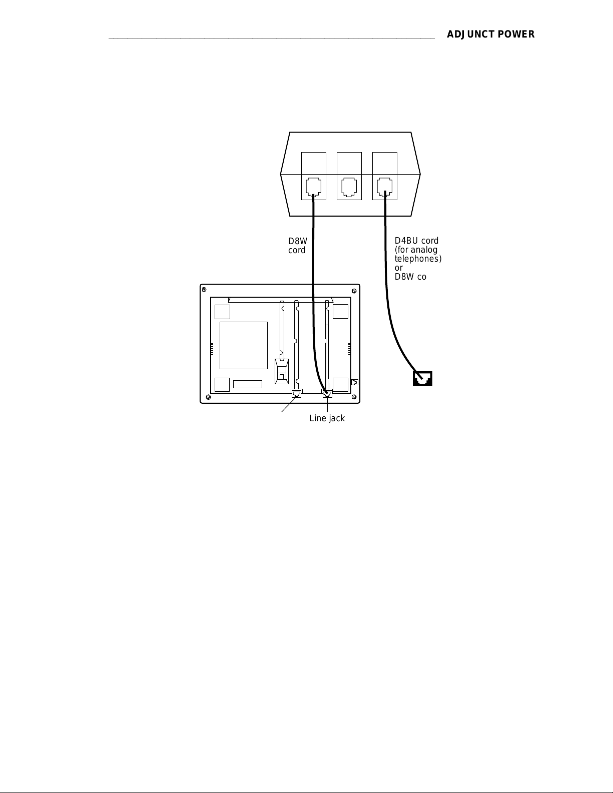
aaaaaaaaaaaaaaaaaaaaaaaaaaaaaaaaaaaaaaaaaaaaaaaaaaaaaaaaaaaaaaaaaaaa
ADJUNCT POWER
MSP-1
Power Supply
D8W
cord
Adjunct jack
Bottom view of
voice terminal/telephone
(7444 shown here)
PHONE
-7 +8
Line jack
OTHER LINE
-2 +5
D4BU cord
(for analog
telephones)
or
D8W cord
(for DCP and
ISDN-T voice
terminals)
Wall jack
FIGURE 2-5. Local Powering Arrangement for: ISDN-T VTs; the DCP 7444 and 8434 VTs
(for their VF Displays); and Adjuncts Connected to All Telephones Except the 8102
2-37
Page 78

ADJUNCT POWER
aaaaaaaaaaaaaaaaaaaaaaaaaaaaaaaaaaaaaaaaaaaaaaaaaaaaaaaaa
PHONE
-7 +8
OTHER LINE
D4BU
cord
-2 +5
MSP-1
Power Supply
Adjunct jack
(on the rear
of telephone)
Power jack
Line jack
D4BU cord
or
2–wire cord
Wall Jack
Bottom view of
the 8102 telephone
FIGURE 2-6. Local Powering Arrangement for Adjuncts Connected to the 8102 Analog Telephone
2-38
Page 79

aaaaaaaaaaaaaaaaaaaaaaaaaaaaaaaaaaaaaaaaaaaaaaaaaaaaaaaaaaaaaaaaaaaaa
ADMINISTRATION
ADMINISTRATION
This section contains some of the information necessary to administer the different voice terminals on DEFINITY G1, G2, G3, System 75, or System 85. It also provides the caveats required
when administering some of the newer voice terminals to the older systems. Other administration information for DEFINITY G1 and G3 or System 75 is provided in the DEFINITY G1 and G3
and System 75 Implementation and Administration manuals. The administration information for
DEFINITY G2 and System 85 is provided in the System 85 and DEFINITY G2 Translation Service Manual.
Important: The sections of this manual which describe the newer voice terminals provide
detailed information on administering that voice terminal. In most cases,
diagrams of the button numbering schemes are also provided. For example, if
you want to administer a 7407 Plus voice terminal, see the section on the 7407
Voice Terminals under the tab labeled 7400 Series..
Aliasing
When some of the newer voice terminals are used with some older versions of the switches, the
administration procedures of the switch does not allow for the use of the new terminals. These
new terminals must be administered using the administration procedures of a similar older terminal. This is called ‘‘aliasing’’ a set.
When aliasing is used to administer a voice terminal, often the ‘‘old’’ screen used in administering
buttons and features displays more buttons than can actually be assigned to the new terminal.
These differences are provided in this section also.
The following tables list the aliases used in administering the terminals. If the terminal you are
administering is not listed in the tables, then it is administered as itself in all versions of the
switch.
2-39
Page 80

ADMINISTRATION
TABLE 2-F. DEFINITY G1 and System 75 Voice Terminal Administration
bbbbbbbbbbbbbbbbbbbbbbbbbbbbbbbbbbbbbbbbbbbbbbbbbbbbbbbbbbbbbbbbbbbbbbb
c
c
c
VOICE
c
TERMINAL
bbbbbbbbbbbbbbbbbbbbbbbbbbbbbbbbbbbbbbbbbbbbbbbbbbbbbbbbbbbbbbbbbbbbbbb
c
bbbbbbbbbbbbbbbbbbbbbbbbbbbbbbbbbbbbbbbbbbbbbbbbbbbbbbbbbbbbbbbbbbbbbbb
c
8101/8102/8110 2500
bbbbbbbbbbbbbbbbbbbbbbbbbbbbbbbbbbbbbbbbbbbbbbbbbbbbbbbbbbbbbbbbbbbbbbb
c
c
7102A 7101A
bbbbbbbbbbbbbbbbbbbbbbbbbbbbbbbbbbbbbbbbbbbbbbbbbbbbbbbbbbbbbbbbbbbbbbb
c
c
7104A
c
bbbbbbbbbbbbbbbbbbbbbbbbbbbbbbbbbbbbbbbbbbbbbbbbbbbbbbbbbbbbbbbbbbbbbbb
c
c
7203H X
bbbbbbbbbbbbbbbbbbbbbbbbbbbbbbbbbbbbbbbbbbbbbbbbbbbbbbbbbbbbbbbbbbbbbbb
c
7205H X
c
bbbbbbbbbbbbbbbbbbbbbbbbbbbbbbbbbbbbbbbbbbbbbbbbbbbbbbbbbbbbbbbbbbbbbbb
c
"MERLIN"’**
c
c
SMALL
bbbbbbbbbbbbbbbbbbbbbbbbbbbbbbbbbbbbbbbbbbbbbbbbbbbbbbbbbbbbbbbbbbbbbbb
c
"MERLIN"
c
c
MEDIUM
bbbbbbbbbbbbbbbbbbbbbbbbbbbbbbbbbbbbbbbbbbbbbbbbbbbbbbbbbbbbbbbbbbbbbbb
c
"MERLIN"
c
c
LARGE
bbbbbbbbbbbbbbbbbbbbbbbbbbbbbbbbbbbbbbbbbbbbbbbbbbbbbbbbbbbbbbbbbbbbbbb
c
c
7401D 7403D S
bbbbbbbbbbbbbbbbbbbbbbbbbbbbbbbbbbbbbbbbbbbbbbbbbbbbbbbbbbbbbbbbbbbbbbb
c
7401 Plus 7403D
c
bbbbbbbbbbbbbbbbbbbbbbbbbbbbbbbbbbbbbbbbbbbbbbbbbbbbbbbbbbbbbbbbbbbbbbb
c
7402 Plus 7403D
c
bbbbbbbbbbbbbbbbbbbbbbbbbbbbbbbbbbbbbbbbbbbbbbbbbbbbbbbbbbbbbbbbbbbbbbb
c
c
7406
c
bbbbbbbbbbbbbbbbbbbbbbbbbbbbbbbbbbbbbbbbbbbbbbbbbbbbbbbbbbbbbbbbbbbbbbb
c
7406BIS 7405D S
c
bbbbbbbbbbbbbbbbbbbbbbbbbbbbbbbbbbbbbbbbbbbbbbbbbbbbbbbbbbbbbbbbbbbbbbb
c
c
7406 Plus 7405D
c
bbbbbbbbbbbbbbbbbbbbbbbbbbbbbbbbbbbbbbbbbbbbbbbbbbbbbbbbbbbbbbbbbbbbbbb
c
c
7407D
c
bbbbbbbbbbbbbbbbbbbbbbbbbbbbbbbbbbbbbbbbbbbbbbbbbbbbbbbbbbbbbbbbbbbbbbb
c
c
Enhanced 7407D
c
bbbbbbbbbbbbbbbbbbbbbbbbbbbbbbbbbbbbbbbbbbbbbbbbbbbbbbbbbbbbbbbbbbbbbbb
c
c
7407 Plus
c
bbbbbbbbbbbbbbbbbbbbbbbbbbbbbbbbbbbbbbbbbbbbbbbbbbbbbbbbbbbbbbbbbbbbbbb
c
c
7410 7403D
bbbbbbbbbbbbbbbbbbbbbbbbbbbbbbbbbbbbbbbbbbbbbbbbbbbbbbbbbbbbbbbbbbbbbbb
c
7410 Plus 7403D
c
bbbbbbbbbbbbbbbbbbbbbbbbbbbbbbbbbbbbbbbbbbbbbbbbbbbbbbbbbbbbbbbbbbbbbbb
c
7434 7405D
c
bbbbbbbbbbbbbbbbbbbbbbbbbbbbbbbbbbbbbbbbbbbbbbbbbbbbbbbbbbbbbbbbbbbbbbbc
aaaaaaaaaaaaaaaaaaaaaaaaaaaaaaaaaaaaaaaaaaaaaaaaaaaaaaaaa
c
c
bbbbbbbbbbbbbbbbbbbbbbbbbbbbbbbbbbbbbbbbbbbbbbbbbbb
c
c
c
c
S75 R1V1
c
c
c
c
c
c
c
c
c
c
c
c
7101A
c
c
c
c
or 2500*
c
c
c
c
c
c
c
c
c
c
c
c
c
c
c
c
c
c
c
c
c
c
c
c
c
c
c
c
c
c
c
c
c
c
c
c
c
c
c
c
7405D
c
c
DD
c
c
c
c
c
c
c
c
c
c
c
c
c
c
7405D
c
c
DD
c
c
c
c
7405D
c
c
c
c
DD
c
c
7405D
c
c
c
c
DD
c
c
c
c
c
c
c
c
c
c
c
c
c
c
c
c
S75 R1V2
c
c
c
c
c
c
c
c
c
c
c
c
c
c
c
c
c
c
c
c
c
c
SYSTEM
c
c
S75 R1V3
c
7303S
7305S
7305S
c
c
or 7406BIS
S
S
7406D
S
7407D
7407D
c
c
G1 and G3
c
c
c
c
c
7410D
c
c
7401D
7410D
c
c
c
c
c
c
c
c
c
c
c
c
c
c
c
c
c
c
c
c
c
c
c
c
c
c
c
c
c
c
c
c
c
c
c
c
c
c
c
c
c
c
c
c
c
c
c
c
c
c
c
c
c
c
2-40
S = Administered as Self
Page 81

aaaaaaaaaaaaaaaaaaaaaaaaaaaaaaaaaaaaaaaaaaaaaaaaaaaaaaaaaaaaaaaaaaaaa
ADMINISTRATION
TABLE 2-F
(continued).
DEFINITY G1 and System 75 Voice Terminal Administration
X = Not Allowed
DD = Digital Display Module
* If equipped with a message waiting adjunct, administer as a 7101A; otherwise, administer as 2500.
** MERLIN Communications System
2-41
Page 82

ADMINISTRATION
aaaaaaaaaaaaaaaaaaaaaaaaaaaaaaaaaaaaaaaaaaaaaaaaaaaaaaaaa
TABLE 2-F
(continued).
DEFINITY G1 and System 75 Voice Terminal Administration
bbbbbbbbbbbbbbbbbbbbbbbbbbbbbbbbbbbbbbbbbbbbbbbbbbbbbbbbbbbbbbbbb
c
c
VOICE
c
TERMINAL
bbbbbbbbbbbbbbbbbbbbbbbbbbbbbbbbbbbbbbbbbbbbbbbbbbbbbbbbbbbbbbbbb
c
bbbbbbbbbbbbbbbbbbbbbbbbbbbbbbbbbbbbbbbbbbbbbbbbbbbbbbbbbbbbbbbbb
c
7444
c
bbbbbbbbbbbbbbbbbbbbbbbbbbbbbbbbbbbbbbbbbbbbbbbbbbbbbbbbbbbbbbbbb
c
8403 7405**
bbbbbbbbbbbbbbbbbbbbbbbbbbbbbbbbbbbbbbbbbbbbbbbbbbbbbbbbbbbbbbbbb
c
c
8410B 7403
bbbbbbbbbbbbbbbbbbbbbbbbbbbbbbbbbbbbbbbbbbbbbbbbbbbbbbbbbbbbbbbbb
c
8410D 7405+D***
bbbbbbbbbbbbbbbbbbbbbbbbbbbbbbbbbbbbbbbbbbbbbbbbbbbbbbbbbbbbbbbbbc
DD = Digital Display Module
*CAVEATS for administration of the 7444 voice terminal:
If the 7444 voice terminal is administered as a 7405D or a 7407D, the following caveats apply:
d
Only 10 call appearance buttons can be administered with two lights, a red and a green light.
d
If the voice terminal is administered as a 7407D, the S1 switch on the back of the 7444 voice terminal must be in the OFF position.
When the 7444 voice terminal is administered as a 7405D or a 7434 voice terminal, the following caveats
apply:
c
c
bbbbbbbbbbbbbbbbbbbbbbbbbbbbbbbbbbbbbbbbbbbbbbbbbbb
c
c
c
c
S75 R1V1 S75 R1V2
c
c
c
c
7405D 7405D 7434D
c
c
DD
c
c
c
c
c
c
c
c
c
c
c
c
c
c
c
c
SYSTEM
c
S75 R1V3 G1 and G3
c
c
or 7407D*
c
c
c
c
c
or 7407D*
c
c
7410***
c
c
c
c
c
c
c
c
c
c
c
c
d
The S1 switch on the back of the 7444 voice terminal must be in the ON position.
d
Only one line of the display will show switch-related information.
When a 7444 is administered as a 7434, DEFINITY G1 allows a maximum of 10 appearances of the primary line while DEFINITY G2 allows a maximum of 12 appearances. Each switch handles appearances of
other lines (that is, lines used in Bridging, Call Pickup, etc.) in a different manner. Information about
administering these appearances can be found in switch documentation and help screens.
** If the 8403 is connected to a DEFINITY G3V3 (and later), the 8403 can be administered as itself.
*** If the 8410B is connected to a DEFINITY G3i or G3r, it can be administered as a 7410 Plus. If the
8410B or 8410D is connected to a DEFINITY G3V3 (or later), the set can be administered as itself.
2-42
Page 83

aaaaaaaaaaaaaaaaaaaaaaaaaaaaaaaaaaaaaaaaaaaaaaaaaaaaaaaaaaaaaaaaaaaaa
ADMINISTRATION
TABLE 2-F
(continued).
DEFINITY G1 and System 75 Voice Terminal Administration
bbbbbbbbbbbbbbbbbbbbbbbbbbbbbbbbbbbbbbbbbbbbbbbbbbbbbbbbbbbbbbbbbbbbbbbbbbb
c
c
c
bbbbbbbbbbbbbbbbbbbbbbbbbbbbbbbbbbbbbbbbbbbbbbbbbbbbbbbbbbbbbbbbbbbbbbbbbbb
c
bbbbbbbbbbbbbbbbbbbbbbbbbbbbbbbbbbbbbbbbbbbbbbbbbbbbbbbbbbbbbbbbbbbbbbbbbbb
c
8434 (for
c
extra features)*
bbbbbbbbbbbbbbbbbbbbbbbbbbbbbbbbbbbbbbbbbbbbbbbbbbbbbbbbbbbbbbbbbbbbbbbbbbb
c
8434 (for
c
additional coverage)*
c
bbbbbbbbbbbbbbbbbbbbbbbbbbbbbbbbbbbbbbbbbbbbbbbbbbbbbbbbbbbbbbbbbbbbbbbbbbb
c
602 CALLMASTER XX S
bbbbbbbbbbbbbbbbbbbbbbbbbbbbbbbbbbbbbbbbbbbbbbbbbbbbbbbbbbbbbbbbbbbbbbbbbbb
c
CALLMASTER II & III X
bbbbbbbbbbbbbbbbbbbbbbbbbbbbbbbbbbbbbbbbbbbbbbbbbbbbbbbbbbbbbbbbbbbbbbbbbbb
c
c
7505 ISDN XS
bbbbbbbbbbbbbbbbbbbbbbbbbbbbbbbbbbbbbbbbbbbbbbbbbbbbbbbbbbbbbbbbbbbbbbbbbbb
c
7506 ISDN XS
bbbbbbbbbbbbbbbbbbbbbbbbbbbbbbbbbbbbbbbbbbbbbbbbbbbbbbbbbbbbbbbbbbbbbbbbbbb
c
7507 ISDN XS
c
bbbbbbbbbbbbbbbbbbbbbbbbbbbbbbbbbbbbbbbbbbbbbbbbbbbbbbbbbbbbbbbbbbbbbbbbbbb
c
8503T XS
bbbbbbbbbbbbbbbbbbbbbbbbbbbbbbbbbbbbbbbbbbbbbbbbbbbbbbbbbbbbbbbbbbbbbbbbbbb
c
8510T X S**
c
bbbbbbbbbbbbbbbbbbbbbbbbbbbbbbbbbbbbbbbbbbbbbbbbbbbbbbbbbbbbbbbbbbbbbbbbbbb
c
8520T X
bbbbbbbbbbbbbbbbbbbbbbbbbbbbbbbbbbbbbbbbbbbbbbbbbbbbbbbbbbbbbbbbbbbbbbbbbbb
c
MDC 9000 7303S Hybrid***
bbbbbbbbbbbbbbbbbbbbbbbbbbbbbbbbbbbbbbbbbbbbbbbbbbbbbbbbbbbbbbbbbbbbbbbbbbb
c
c
MDW 9000 7303S Hybrid***
bbbbbbbbbbbbbbbbbbbbbbbbbbbbbbbbbbbbbbbbbbbbbbbbbbbbbbbbbbbbbbbbbbbbbbbbbbbc
VOICE
TERMINAL
c
c
bbbbbbbbbbbbbbbbbbbbbbbbbbbbbbbbbbbbbbbbbbbbbbbbbbb
c
c
c
c
S75 R1V1
c
c
c
c
c
c
c
c
c
c
c
c
c
c
c
c
c
c
c
c
c
c
c
c
c
c
c
c
c
c
c
c
c
c
c
c
c
c
c
c
c
c
c
S75 R1V2
c
c
c
c
c
SYSTEM
7405+D+F
X
X
c
S75 R1V3
c
c
c
c
602 CALLMASTER
c
c
G1 and G3
c
c
c
7434+D
c
c
c
c
c
c
c
c
c
c
S
c
c
c
c
c
c
c
c
c
c
c
c
c
c
c
c
c
c
c
c
c
c
c
c
c
S = Administered as Self
X = Not Allowed
+D = with Display Module
+F = with Feature Key Module
* CAVEATS for administration of the 8434 voice terminal:
The 8434 may be aliased as a 7405+D+F to support all system features. However, in this case, while all the call
appearance/feature buttons AND the softkey features will be functional, there can be a maximum of only 10 call
appearances. On the 7405, the Display Module is a 1-line display, and thus the 1-line display option should be
selected.
On some systems, the 8434 can be aliased as a 7434+D or a 7444 to support coverage. In this case, there can be
up to 34 call appearances (including bridged call appearances), but the 15 softkey features will NOT be functional
because the Feature Key Module is not allowed with the 7434 or 7444. On the 7434, the Display Module is a 1-line
display, and thus the 1-line display option should be selected. If the set is administered as a 7444, it can be
optioned for a 2-line display.
An 8434 connected to a DEFINITY G3V2 can be administered as a 7444; an 8434 connected to a DEFINITY G3V3
(or later) can be administered as itself.
**An 8510T voice terminal connected to a DEFINITY G1 or G3 can be administered as itself, but an 8510 data
terminal must be administered as a 7507.
***A MDC 9000 Cordless Telephone or a MDW 9000 Wireless Telephone connected to a DEFINITY G3V3
(or later) can be administered as itself.
2-43
Page 84

ADMINISTRATION
aaaaaaaaaaaaaaaaaaaaaaaaaaaaaaaaaaaaaaaaaaaaaaaaaaaaaaaaa
TABLE 2-G. DEFINITY G1 and System 75 Terminal and Module Administration
bbbbbbbbbbbbbbbbbbbbbbbbbbbbbbbbbbbbbbbbbbbbbbbbbbbbbbbbbbbbbbbbbbbbbbbbbbbbbbbb
c
c
c
bbbbbbbbbbbbbbbbbbbbbbbbbbbbbbbbbbbbbbbbbbbbbbbbbbbbbbbbbbbbbbbbbbbbbbbbbbbbbbbb
c
bbbbbbbbbbbbbbbbbbbbbbbbbbbbbbbbbbbbbbbbbbbbbbbbbbbbbbbbbbbbbbbbbbbbbbbbbbbbbbbb
c
PC/PBX PLATFORM
c
bbbbbbbbbbbbbbbbbbbbbbbbbbbbbbbbbbbbbbbbbbbbbbbbbbbbbbbbbbbbbbbbbbbbbbbbbbbbbbbb
c
MPDM S
c
bbbbbbbbbbbbbbbbbbbbbbbbbbbbbbbbbbbbbbbbbbbbbbbbbbbbbbbbbbbbbbbbbbbbbbbbbbbbbbbb
c
MTDM S
bbbbbbbbbbbbbbbbbbbbbbbbbbbbbbbbbbbbbbbbbbbbbbbbbbbbbbbbbbbbbbbbbbbbbbbbbbbbbbbb
c
7400A DM PDM or TDM (modem pool only) S
c
bbbbbbbbbbbbbbbbbbbbbbbbbbbbbbbbbbbbbbbbbbbbbbbbbbbbbbbbbbbbbbbbbbbbbbbbbbbbbbbb
c
7400B & 7400B Plus DM PDM (data only) or DM (voice and data)
bbbbbbbbbbbbbbbbbbbbbbbbbbbbbbbbbbbbbbbbbbbbbbbbbbbbbbbbbbbbbbbbbbbbbbbbbbbbbbbb
c
c
High Speed Link PDM
bbbbbbbbbbbbbbbbbbbbbbbbbbbbbbbbbbbbbbbbbbbbbbbbbbbbbbbbbbbbbbbbbbbbbbbbbbbbbbbb
c
3270A DCP PDM
c
bbbbbbbbbbbbbbbbbbbbbbbbbbbbbbbbbbbbbbbbbbbbbbbbbbbbbbbbbbbbbbbbbbbbbbbbbbbbbbbb
c
3270C DCP PDM
bbbbbbbbbbbbbbbbbbbbbbbbbbbbbbbbbbbbbbbbbbbbbbbbbbbbbbbbbbbbbbbbbbbbbbbbbbbbbbbb
c
3270T DCP PDM
c
bbbbbbbbbbbbbbbbbbbbbbbbbbbbbbbbbbbbbbbbbbbbbbbbbbbbbbbbbbbbbbbbbbbbbbbbbbbbbbbb
c
PC/ISDN PLATFORM XXXX
bbbbbbbbbbbbbbbbbbbbbbbbbbbbbbbbbbbbbbbbbbbbbbbbbbbbbbbbbbbbbbbbbbbbbbbbbbbbbbbbc
PCs AND
DIGITAL MODULES
c
c
bbbbbbbbbbbbbbbbbbbbbbbbbbbbbbbbbbbbbbbbbbbbbbbbbbbbb
c
c
c
c
S75 R1V1 S75 R1V2
c
c
c
c
7405D
c
c
DD & DMcc
c
c
c
c
c
c
c
c
c
c
c
c
c
c
c
c
c
c
c
c
c
c
c
c
c
c
c
c
c
c
c
c
c
c
c
c
SYSTEM
c
S75 R1V3
c
c
c
c
PC
c
c
c
c
c
c
c
c
G1 and G3
S
c
c
c
c
c
c
c
c
c
c
c
c
c
c
c
c
c
c
c
c
c
S = Administered as Self
X = Not Allowed
PC = Personal Computer
DD = Digital Display Module
DM = Data Module
TDM = Trunk Data Module
PDM = Processor Data Module
2-44
Page 85

aaaaaaaaaaaaaaaaaaaaaaaaaaaaaaaaaaaaaaaaaaaaaaaaaaaaaaaaaaaaaaaaaaaaa
TABLE 2-H. DEFINITY G2 and System 85 Voice Terminal Administration
bbbbbbbbbbbbbbbbbbbbbbbbbbbbbbbbbbbbbbbbbbbbbbbbbbbbbbbbbbbbbbbbbbbbbbbbbbbb
c
c
VOICE
c
TERMINAL
bbbbbbbbbbbbbbbbbbbbbbbbbbbbbbbbbbbbbbbbbbbbbbbbbbbbbbbbbbbbbbbbbbbbbbbbbbbb
c
bbbbbbbbbbbbbbbbbbbbbbbbbbbbbbbbbbbbbbbbbbbbbbbbbbbbbbbbbbbbbbbbbbbbbbbbbbbb
c
500 A
bbbbbbbbbbbbbbbbbbbbbbbbbbbbbbbbbbbbbbbbbbbbbbbbbbbbbbbbbbbbbbbbbbbbbbbbbbbb
c
2500 A
bbbbbbbbbbbbbbbbbbbbbbbbbbbbbbbbbbbbbbbbbbbbbbbbbbbbbbbbbbbbbbbbbbbbbbbbbbbb
c
2500 YMGK A
c
bbbbbbbbbbbbbbbbbbbbbbbbbbbbbbbbbbbbbbbbbbbbbbbbbbbbbbbbbbbbbbbbbbbbbbbbbbbb
c
7101A A
bbbbbbbbbbbbbbbbbbbbbbbbbbbbbbbbbbbbbbbbbbbbbbbbbbbbbbbbbbbbbbbbbbbbbbbbbbbb
c
7102A A
c
bbbbbbbbbbbbbbbbbbbbbbbbbbbbbbbbbbbbbbbbbbbbbbbbbbbbbbbbbbbbbbbbbbbbbbbbbbbb
c
7102 Plus A
bbbbbbbbbbbbbbbbbbbbbbbbbbbbbbbbbbbbbbbbbbbbbbbbbbbbbbbbbbbbbbbbbbbbbbbbbbbb
c
7103A A
bbbbbbbbbbbbbbbbbbbbbbbbbbbbbbbbbbbbbbbbbbbbbbbbbbbbbbbbbbbbbbbbbbbbbbbbbbbb
c
c
7104A A
bbbbbbbbbbbbbbbbbbbbbbbbbbbbbbbbbbbbbbbbbbbbbbbbbbbbbbbbbbbbbbbbbbbbbbbbbbbb
c
10 MET 7203H
bbbbbbbbbbbbbbbbbbbbbbbbbbbbbbbbbbbbbbbbbbbbbbbbbbbbbbbbbbbbbbbbbbbbbbbbbbbb
c
20 MET 7205H
c
bbbbbbbbbbbbbbbbbbbbbbbbbbbbbbbbbbbbbbbbbbbbbbbbbbbbbbbbbbbbbbbbbbbbbbbbbbbb
c
30 MET 7205H
bbbbbbbbbbbbbbbbbbbbbbbbbbbbbbbbbbbbbbbbbbbbbbbbbbbbbbbbbbbbbbbbbbbbbbbbbbbb
c
"MERLIN"
c
SMALL
c
bbbbbbbbbbbbbbbbbbbbbbbbbbbbbbbbbbbbbbbbbbbbbbbbbbbbbbbbbbbbbbbbbbbbbbbbbbbb
c
"MERLIN"
c
MEDIUM
bbbbbbbbbbbbbbbbbbbbbbbbbbbbbbbbbbbbbbbbbbbbbbbbbbbbbbbbbbbbbbbbbbbbbbbbbbbb
c
"MERLIN"
c
c
LARGE
bbbbbbbbbbbbbbbbbbbbbbbbbbbbbbbbbbbbbbbbbbbbbbbbbbbbbbbbbbbbbbbbbbbbbbbbbbbb
c
7401D 7403D S
bbbbbbbbbbbbbbbbbbbbbbbbbbbbbbbbbbbbbbbbbbbbbbbbbbbbbbbbbbbbbbbbbbbbbbbbbbbb
c
7401 Plus 7403D 7401D
c
bbbbbbbbbbbbbbbbbbbbbbbbbbbbbbbbbbbbbbbbbbbbbbbbbbbbbbbbbbbbbbbbbbbbbbbbbbbb
c
7402 Plus 7403D
bbbbbbbbbbbbbbbbbbbbbbbbbbbbbbbbbbbbbbbbbbbbbbbbbbbbbbbbbbbbbbbbbbbbbbbbbbbb
c
7404 7403D DM
bbbbbbbbbbbbbbbbbbbbbbbbbbbbbbbbbbbbbbbbbbbbbbbbbbbbbbbbbbbbbbbbbbbbbbbbbbbb
c
c
7406D 7405D DD S
bbbbbbbbbbbbbbbbbbbbbbbbbbbbbbbbbbbbbbbbbbbbbbbbbbbbbbbbbbbbbbbbbbbbbbbbbbbb
c
7406BIS 7405D DD S
bbbbbbbbbbbbbbbbbbbbbbbbbbbbbbbbbbbbbbbbbbbbbbbbbbbbbbbbbbbbbbbbbbbbbbbbbbbb
c
c
7406 Plus 7405D DD
c
bbbbbbbbbbbbbbbbbbbbbbbbbbbbbbbbbbbbbbbbbbbbbbbbbbbbbbbbbbbbbbbbbbbbbbbbbbbb
c
c
7407D
bbbbbbbbbbbbbbbbbbbbbbbbbbbbbbbbbbbbbbbbbbbbbbbbbbbbbbbbbbbbbbbbbbbbbbbbbbbb
c
c
Enhanced 7407D
c
bbbbbbbbbbbbbbbbbbbbbbbbbbbbbbbbbbbbbbbbbbbbbbbbbbbbbbbbbbbbbbbbbbbbbbbbbbbb
c
c
7407 Plus
c
bbbbbbbbbbbbbbbbbbbbbbbbbbbbbbbbbbbbbbbbbbbbbbbbbbbbbbbbbbbbbbbbbbbbbbbbbbbbc
c
c
bbbbbbbbbbbbbbbbbbbbbbbbbbbbbbbbbbbbbbbbbbbbbbbbbbbbbbbbb
c
c
c
c
S85 R2V1
c
c
c
c
c
c
c
c
c
c
c
c
c
c
c
c
c
c
c
c
c
c
c
c
c
c
c
c
c
c
c
c
c
c
c
c
c
c
c
c
c
c
c
c
c
c
c
c
c
c
c
c
c
c
c
c
c
c
c
c
c
c
c
c
c
c
c
c
c
c
c
c
7405
c
c
DD
c
c
c
c
7405D
c
c
DD
c
c
7405D
c
c
DD
c
c
c
c
c
S85 R2V2
c
c
c
c
c
c
c
c
c
c
c
c
SYSTEM
c
S85 R2V3
c
c
X
7303S
7305S
S
S
7407D
7407D
c
S85 R2V4
c
c
c
c
c
c
c
c
c
c
c
c
c
ADMINISTRATION
c
c
c
c
G2
c
c
c
c
c
c
c
c
c
c
c
c
c
c
c
c
c
c
c
c
c
c
c
c
c
c
c
c
c
7410D
c
c
c
c
c
c
7406D
or 7406BIS
c
c
c
c
c
c
c
c
c
c
c
X = Not Allowed
A = Administered as Analog On-premises or Off-premises
S = Administered as Self
DD = Digital Display Module
DM = Data Module (DTDM or ADS)
2-45
Page 86

ADMINISTRATION
aaaaaaaaaaaaaaaaaaaaaaaaaaaaaaaaaaaaaaaaaaaaaaaaaaaaaaaaa
TABLE 2-H
(continued).
DEFINITY G2 and System 85 Voice Terminal Administration
bbbbbbbbbbbbbbbbbbbbbbbbbbbbbbbbbbbbbbbbbbbbbbbbbbbbbbbbbbbbbbbbbbbbbbbbbbbbb
c
c
VOICE
c
TERMINAL
bbbbbbbbbbbbbbbbbbbbbbbbbbbbbbbbbbbbbbbbbbbbbbbbbbbbbbbbbbbbbbbbbbbbbbbbbbbbb
c
bbbbbbbbbbbbbbbbbbbbbbbbbbbbbbbbbbbbbbbbbbbbbbbbbbbbbbbbbbbbbbbbbbbbbbbbbbbbb
c
7410D 7403D S
bbbbbbbbbbbbbbbbbbbbbbbbbbbbbbbbbbbbbbbbbbbbbbbbbbbbbbbbbbbbbbbbbbbbbbbbbbbbb
c
7410 Plus 7403D 7410D
bbbbbbbbbbbbbbbbbbbbbbbbbbbbbbbbbbbbbbbbbbbbbbbbbbbbbbbbbbbbbbbbbbbbbbbbbbbbb
c
7434D 7405D S
c
bbbbbbbbbbbbbbbbbbbbbbbbbbbbbbbbbbbbbbbbbbbbbbbbbbbbbbbbbbbbbbbbbbbbbbbbbbbbb
c
7444 7405D DD
c
bbbbbbbbbbbbbbbbbbbbbbbbbbbbbbbbbbbbbbbbbbbbbbbbbbbbbbbbbbbbbbbbbbbbbbbbbbbbb
c
8403 7405
c
bbbbbbbbbbbbbbbbbbbbbbbbbbbbbbbbbbbbbbbbbbbbbbbbbbbbbbbbbbbbbbbbbbbbbbbbbbbbb
c
8410B 7403
bbbbbbbbbbbbbbbbbbbbbbbbbbbbbbbbbbbbbbbbbbbbbbbbbbbbbbbbbbbbbbbbbbbbbbbbbbbbb
c
8410D 7405+D
c
bbbbbbbbbbbbbbbbbbbbbbbbbbbbbbbbbbbbbbbbbbbbbbbbbbbbbbbbbbbbbbbbbbbbbbbbbbbbbc
S = Administered as Self
DD = Digital Display Module
*CAVEATS for administration of the 7444 voice terminal:
If the 7444 voice terminal is administered as a 7405D or a 7407D, the following caveats apply:
d
c
c
bbbbbbbbbbbbbbbbbbbbbbbbbbbbbbbbbbbbbbbbbbbbbbbbbbbbbbbbbbbbbbb
c
c
c
c
S85 R2V1
c
c
c
c
c
c
c
c
c
c
c
c
c
c
c
c
c
c
c
c
c
c
c
c
c
c
Only 10 call appearance buttons can be administered with two lights, a red and a green light.
c
S85 R2V2
c
c
c
c
c
SYSTEM
c
S85 R2V3
c
c
c
S85 R2V4 G2
c
c
c
c
c
c
c
c
c
7405D DD 7434D
or 7407D*
c
c
or 7407D*
c
c
7410D
c
c
c
c
c
c
c
c
c
c
c
c
c
c
c
c
c
d
If the voice terminal is administered as a 7407D, the S1 switch on the back of the 7444 voice terminal
must be in the OFF position.
When the 7444 voice terminal is administered as a 7405D or a 7434 voice terminal, the following caveats apply:
d
The S1 switch on the back of the 7444 voice terminal must be in the ON position.
d
Only one line of the display will show switch-related information.
When a 7444 is administered as a 7434, DEFINITY G1 allows a maximum of 10 appearances of the primary line
while DEFINITY G2 allows a maximum of 12 appearances. Each switch handles appearances of other lines (that
is, lines used in Bridging, Call Pickup, etc.) in a different manner. Information about administering these appearances can be found in switch documentation and help screens.
2-46
Page 87

aaaaaaaaaaaaaaaaaaaaaaaaaaaaaaaaaaaaaaaaaaaaaaaaaaaaaaaaaaaaaaaaaaaaa
ADMINISTRATION
TABLE 2-H
(continued).
DEFINITY G2 and System 85 Voice Terminal Administration
bbbbbbbbbbbbbbbbbbbbbbbbbbbbbbbbbbbbbbbbbbbbbbbbbbbbbbbbbbbbbbbbbbbbbbbbbbbbbbbbbbbbb
c
c
c
bbbbbbbbbbbbbbbbbbbbbbbbbbbbbbbbbbbbbbbbbbbbbbbbbbbbbbbbbbbbbbbbbbbbbbbbbbbbbbbbbbbbb
c
bbbbbbbbbbbbbbbbbbbbbbbbbbbbbbbbbbbbbbbbbbbbbbbbbbbbbbbbbbbbbbbbbbbbbbbbbbbbbbbbbbbbb
c
8434 (for
c
extra features)*
bbbbbbbbbbbbbbbbbbbbbbbbbbbbbbbbbbbbbbbbbbbbbbbbbbbbbbbbbbbbbbbbbbbbbbbbbbbbbbbbbbbbb
c
8434 (for
c
additional coverage)*
c
bbbbbbbbbbbbbbbbbbbbbbbbbbbbbbbbbbbbbbbbbbbbbbbbbbbbbbbbbbbbbbbbbbbbbbbbbbbbbbbbbbbbb
c
602 CALLMASTER XS
bbbbbbbbbbbbbbbbbbbbbbbbbbbbbbbbbbbbbbbbbbbbbbbbbbbbbbbbbbbbbbbbbbbbbbbbbbbbbbbbbbbbb
c
CALLMASTER II & III X
bbbbbbbbbbbbbbbbbbbbbbbbbbbbbbbbbbbbbbbbbbbbbbbbbbbbbbbbbbbbbbbbbbbbbbbbbbbbbbbbbbbbb
c
c
7505 ISDN XS
bbbbbbbbbbbbbbbbbbbbbbbbbbbbbbbbbbbbbbbbbbbbbbbbbbbbbbbbbbbbbbbbbbbbbbbbbbbbbbbbbbbbb
c
7506 ISDN XS
bbbbbbbbbbbbbbbbbbbbbbbbbbbbbbbbbbbbbbbbbbbbbbbbbbbbbbbbbbbbbbbbbbbbbbbbbbbbbbbbbbbbb
c
7507 ISDN XS
c
bbbbbbbbbbbbbbbbbbbbbbbbbbbbbbbbbbbbbbbbbbbbbbbbbbbbbbbbbbbbbbbbbbbbbbbbbbbbbbbbbbbbb
c
8503T X 7505
bbbbbbbbbbbbbbbbbbbbbbbbbbbbbbbbbbbbbbbbbbbbbbbbbbbbbbbbbbbbbbbbbbbbbbbbbbbbbbbbbbbbb
c
8510T X 7507
c
bbbbbbbbbbbbbbbbbbbbbbbbbbbbbbbbbbbbbbbbbbbbbbbbbbbbbbbbbbbbbbbbbbbbbbbbbbbbbbbbbbbbb
c
8520T X
bbbbbbbbbbbbbbbbbbbbbbbbbbbbbbbbbbbbbbbbbbbbbbbbbbbbbbbbbbbbbbbbbbbbbbbbbbbbbbbbbbbbb
c
MDC 9000 7303S Hybrid
bbbbbbbbbbbbbbbbbbbbbbbbbbbbbbbbbbbbbbbbbbbbbbbbbbbbbbbbbbbbbbbbbbbbbbbbbbbbbbbbbbbbb
c
c
MDW 9000 7303S Hybrid
bbbbbbbbbbbbbbbbbbbbbbbbbbbbbbbbbbbbbbbbbbbbbbbbbbbbbbbbbbbbbbbbbbbbbbbbbbbbbbbbbbbbbc
VOICE
TERMINAL
c
c
bbbbbbbbbbbbbbbbbbbbbbbbbbbbbbbbbbbbbbbbbbbbbbbbbbbbbbbbbbbbb
c
c
c
c
S85 R2V1
c
c
c
c
c
c
c
c
c
c
c
c
c
c
c
c
c
c
c
c
c
c
c
c
c
c
c
c
c
c
c
c
c
c
c
c
c
c
c
c
c
c
c
S85 R2V2
c
c
c
c
c
SYSTEM
c
S85 R2V3
c
c
7405+D+F
X
602 CALLMASTER
c
S85 R2V4
c
c
c
G2
c
c
c
7434+D
c
c
c
c
c
c
c
c
c
c
7507
c
c
c
c
c
c
c
c
c
c
c
c
c
c
c
c
c
c
c
c
c
c
c
c
c
X = Not Allowed
A = Administered as Analog On-premises or Off-premises
S = Administered as Self
* CAVEATS for administration of the 8434 voice terminal:
The 8434 may be aliased as a 7405+D+F to support all system features. However, in this case, while all the call
appearance/feature buttons AND the softkey features will be functional, there can be a maximum of only 10 call
appearances. On the 7405, the Display Module is a 1-line display, and thus the 1-line display option should be
selected.
On some systems, the 8434 can be aliased as a 7434+D or a 7444 to support coverage. In this case, there can be
up to 34 call appearances (including bridged call appearances), but the 15 softkey features will NOT be functional
because the Feature Key Module is not allowed with the 7434 or 7444. On the 7434, the Display Module is a 1-line
display, and thus the 1-line display option should be selected. If the set is administered as a 7444, it can be optioned
for a 2-line display.
2-47
Page 88

ADMINISTRATION
aaaaaaaaaaaaaaaaaaaaaaaaaaaaaaaaaaaaaaaaaaaaaaaaaaaaaaaaa
TABLE 2-I. DEFINITY G2 and System 85 Terminal and Module Administration
bbbbbbbbbbbbbbbbbbbbbbbbbbbbbbbbbbbbbbbbbbbbbbbbbbbbbbbbbbbbbbbbbbbbbbbbbbbbbbbbbbbb
c
c
DISPLAY TERMINALS
c
c
DIGITAL MODULES
c
bbbbbbbbbbbbbbbbbbbbbbbbbbbbbbbbbbbbbbbbbbbbbbbbbbbbbbbbbbbbbbbbbbbbbbbbbbbbbbbbbbbb
bbbbbbbbbbbbbbbbbbbbbbbbbbbbbbbbbbbbbbbbbbbbbbbbbbbbbbbbbbbbbbbbbbbbbbbbbbbbbbbbbbbb
c
PC/PBX PLATFORM
c
bbbbbbbbbbbbbbbbbbbbbbbbbbbbbbbbbbbbbbbbbbbbbbbbbbbbbbbbbbbbbbbbbbbbbbbbbbbbbbbbbbbb
c
BCT 513 X
c
bbbbbbbbbbbbbbbbbbbbbbbbbbbbbbbbbbbbbbbbbbbbbbbbbbbbbbbbbbbbbbbbbbbbbbbbbbbbbbbbbbbb
c
MPDM PDM
bbbbbbbbbbbbbbbbbbbbbbbbbbbbbbbbbbbbbbbbbbbbbbbbbbbbbbbbbbbbbbbbbbbbbbbbbbbbbbbbbbbb
c
c
MTDM TDM
bbbbbbbbbbbbbbbbbbbbbbbbbbbbbbbbbbbbbbbbbbbbbbbbbbbbbbbbbbbbbbbbbbbbbbbbbbbbbbbbbbbb
c
7400A DM PDM or TDM (modem pool only) S
c
bbbbbbbbbbbbbbbbbbbbbbbbbbbbbbbbbbbbbbbbbbbbbbbbbbbbbbbbbbbbbbbbbbbbbbbbbbbbbbbbbbbb
c
7400B & 7400B Plus DM PDM (data only) or DM (voice and data) S
bbbbbbbbbbbbbbbbbbbbbbbbbbbbbbbbbbbbbbbbbbbbbbbbbbbbbbbbbbbbbbbbbbbbbbbbbbbbbbbbbbbb
c
7500B DM X
c
bbbbbbbbbbbbbbbbbbbbbbbbbbbbbbbbbbbbbbbbbbbbbbbbbbbbbbbbbbbbbbbbbbbbbbbbbbbbbbbbbbbb
c
High Speed Link PDM
bbbbbbbbbbbbbbbbbbbbbbbbbbbbbbbbbbbbbbbbbbbbbbbbbbbbbbbbbbbbbbbbbbbbbbbbbbbbbbbbbbbb
c
3270A DCP PDM
c
bbbbbbbbbbbbbbbbbbbbbbbbbbbbbbbbbbbbbbbbbbbbbbbbbbbbbbbbbbbbbbbbbbbbbbbbbbbbbbbbbbbb
c
3270C DCP PDM
bbbbbbbbbbbbbbbbbbbbbbbbbbbbbbbbbbbbbbbbbbbbbbbbbbbbbbbbbbbbbbbbbbbbbbbbbbbbbbbbbbbb
c
c
3270T DCP PDM
bbbbbbbbbbbbbbbbbbbbbbbbbbbbbbbbbbbbbbbbbbbbbbbbbbbbbbbbbbbbbbbbbbbbbbbbbbbbbbbbbbbb
c
PC/ISDN PLATFORM X GTA
c
bbbbbbbbbbbbbbbbbbbbbbbbbbbbbbbbbbbbbbbbbbbbbbbbbbbbbbbbbbbbbbbbbbbbbbbbbbbbbbbbbbbbc
AND
c
c
bbbbbbbbbbbbbbbbbbbbbbbbbbbbbbbbbbbbbbbbbbbbbbbbbbbbbbbbbb
c
c
c
c
c
c
S85 R2V1 S85 R2V2cc
c
c
c
c
7405D
c
c
DD & DM
c
c
c
c
c
c
c
c
c
c
c
c
c
c
c
c
c
c
c
c
c
c
c
c
c
c
c
c
c
c
c
c
c
c
c
c
c
c
c
c
c
c
c
c
c
SYSTEM
c
c
S85 R2V3 S85 R2V4cc
PT 510D
c
c
EIA PORT
c
c
c
c
c
c
c
PC
c
G2
c
c
c
c
c
c
c
c
c
c
c
c
c
c
c
c
c
c
c
c
c
c
S
c
c
c
c
c
c
c
c
c
c
c
c
S = Administered as Self
X = Not Allowed
PC = Personal Computer
DD = Digital Data Module
DM = Data Module
PDM = Processor Data Module
TDM = Trunk Data Module
GTA = Generalized Terminal Administration (see System 85 and DEFINITY G2
Button and Feature Caveats section)
2-48
Page 89
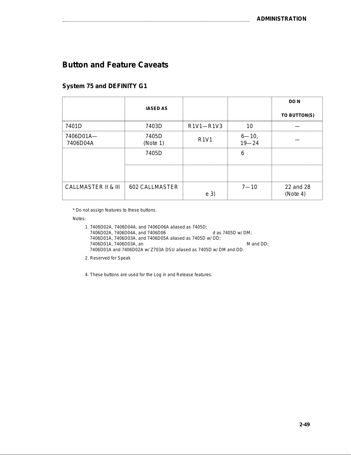
aaaaaaaaaaaaaaaaaaaaaaaaaaaaaaaaaaaaaaaaaaaaaaaaaaaaaaaaaaaaaaaaaaaaa
ADMINISTRATION
Button and Feature Caveats
System 75 and DEFINITY G1
bbbbbbbbbbbbbbbbbbbbbbbbbbbbbbbbbbbbbbbbbbbbbbbbbbbbbbbbbbbbbbbbbbbbbbbbbbbbbbbbbbbbbbbbbbbbbbb
c
c
c
c
bbbbbbbbbbbbbbbbbbbbbbbbbbbbbbbbbbbbbbbbbbbbbbbbbbbbbbbbbbbbbbbbbbbbbbbbbbbbbbbbbbbbbbbbbbbbbbb
bbbbbbbbbbbbbbbbbbbbbbbbbbbbbbbbbbbbbbbbbbbbbbbbbbbbbbbbbbbbbbbbbbbbbbbbbbbbbbbbbbbbbbbbbbbbbbb
c
bbbbbbbbbbbbbbbbbbbbbbbbbbbbbbbbbbbbbbbbbbbbbbbbbbbbbbbbbbbbbbbbbbbbbbbbbbbbbbbbbbbbbbbbbbbbbbb
c
c
c
bbbbbbbbbbbbbbbbbbbbbbbbbbbbbbbbbbbbbbbbbbbbbbbbbbbbbbbbbbbbbbbbbbbbbbbbbbbbbbbbbbbbbbbbbbbbbbb
c
c
c
c
c
c
bbbbbbbbbbbbbbbbbbbbbbbbbbbbbbbbbbbbbbbbbbbbbbbbbbbbbbbbbbbbbbbbbbbbbbbbbbbbbbbbbbbbbbbbbbbbbbb
c
c
c
bbbbbbbbbbbbbbbbbbbbbbbbbbbbbbbbbbbbbbbbbbbbbbbbbbbbbbbbbbbbbbbbbbbbbbbbbbbbbbbbbbbbbbbbbbbbbbbc
TERMINAL ALIASED AS
7401D 7403D R1V1—R1V3 10 —
7406D01A— 7405D 6—10,
7406D04A (Note 1)
7405D 6—10, 2, 3
7406D05A, (Note 1)
7406D06A R1V2—R1V3, 2, 3
CALLMASTER II & III 602 CALLMASTER 7—10
c
c
c
c
c
c
c
c
c
c
c
bbbbbbbbbbbbbbbbbbbbbbbbbbbbbbbbbbbbbbbbbbbbbbbbbbbbbbbbbbbbbbbbbbbbbbbb
c
c
c
Self
c
c
c
c
c
c
c
c
c
c
c
c
c
c
c
c
c
c
c
c
c
c
SWITCH
RELEASE
R1V1
R1V1
G1
R1V3
(Note 3)
c
BUTTONS THAT
c
DO NOT EXIST*
c
c
c
c
c
c
19—24
c
c
c
19—24 (Note 2)
c
c
c
—
c
c
c
c
c
c
ASSIGN FEATURES
c
c
c
c
c
c
c
c
c
c
c
c
c
c
c
c
DO NOT
TO BUTTON(S)
—
(Note 2)
22 and 28
(Note 4)
c
c
c
c
c
c
c
c
c
c
c
c
c
c
c
c
c
c
* Do not assign features to these buttons.
Notes:
1. 7406D02A, 7406D04A, and 7406D06A aliased as 7405D;
7406D02A, 7406D04A, and 7406D06A w/ 7400B Plus aliased as 7405D w/ DM;
7406D01A, 7406D03A, and 7406D05A aliased as 7405D w/ DD;
7406D01A, 7406D03A, and 7406D05A w/ 7400B Plus aliased as 7405D w/ DM and DD;
7406D01A and 7406D02A w/ Z703A DSU aliased as 7405D w/ DM and DD.
2. Reserved for Speaker and Mute.
3. Not supported in earlier releases.
4. These buttons are used for the Log in and Release features.
2-49
Page 90
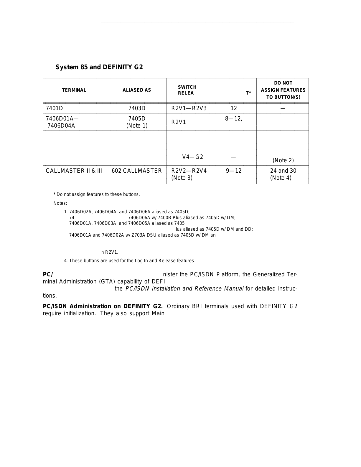
ADMINISTRATION
aaaaaaaaaaaaaaaaaaaaaaaaaaaaaaaaaaaaaaaaaaaaaaaaaaaaaaaaa
System 85 and DEFINITY G2
bbbbbbbbbbbbbbbbbbbbbbbbbbbbbbbbbbbbbbbbbbbbbbbbbbbbbbbbbbbbbbbbbbbbbbbbbbbbbbbbbbbbbbbbbbbbbb
c
c
c
c
bbbbbbbbbbbbbbbbbbbbbbbbbbbbbbbbbbbbbbbbbbbbbbbbbbbbbbbbbbbbbbbbbbbbbbbbbbbbbbbbbbbbbbbbbbbbbb
bbbbbbbbbbbbbbbbbbbbbbbbbbbbbbbbbbbbbbbbbbbbbbbbbbbbbbbbbbbbbbbbbbbbbbbbbbbbbbbbbbbbbbbbbbbbbb
c
bbbbbbbbbbbbbbbbbbbbbbbbbbbbbbbbbbbbbbbbbbbbbbbbbbbbbbbbbbbbbbbbbbbbbbbbbbbbbbbbbbbbbbbbbbbbbb
c
c
c
bbbbbbbbbbbbbbbbbbbbbbbbbbbbbbbbbbbbbbbbbbbbbbbbbbbbbbbbbbbbbbbbbbbbbbbbbbbbbbbbbbbbbbbbbbbbbb
c
c
c
c
c
c
bbbbbbbbbbbbbbbbbbbbbbbbbbbbbbbbbbbbbbbbbbbbbbbbbbbbbbbbbbbbbbbbbbbbbbbbbbbbbbbbbbbbbbbbbbbbbb
c
c
c
bbbbbbbbbbbbbbbbbbbbbbbbbbbbbbbbbbbbbbbbbbbbbbbbbbbbbbbbbbbbbbbbbbbbbbbbbbbbbbbbbbbbbbbbbbbbbbc
TERMINAL ALIASED AS
7401D 7403D R2V1—R2V3 12 —
7406D01A— 7405D 8—12,
7406D04A (Note 1)
7405D 8—12, 14, 15
7406D05A, (Note 1)
7406D06A 14, 15
CALLMASTER II & III 602 CALLMASTER 9—12
c
c
c
c
c
c
c
c
c
c
c
bbbbbbbbbbbbbbbbbbbbbbbbbbbbbbbbbbbbbbbbbbbbbbbbbbbbbbbbbbbbbbbbbbbbbbbb
c
c
c
Self R2V4—G2 —
c
c
c
c
c
SWITCH
c
RELEASE
c
c
c
c
c
R2V1—R2V3
c
c
c
R2V1—R2V3
c
c
c
c
c
c
R2V2—R2V4
c
(Note 3)
c
c
BUTTONS THAT
c
DO NOT EXIST*
c
c
c
c
c
c
31—36
c
c
c
31—36 (Note 2)
c
c
c
c
c
c
c
c
c
ASSIGN FEATURES
c
c
c
c
c
c
c
c
c
c
c
c
c
c
c
c
DO NOT
TO BUTTON(S)
—
(Note 2)
24 and 30
(Note 4)
c
c
c
c
c
c
c
c
c
c
c
c
c
c
c
c
c
c
* Do not assign features to these buttons.
Notes:
1. 7406D02A, 7406D04A, and 7406D06A aliased as 7405D;
7406D02A, 7406D04A, and 7406D06A w/ 7400B Plus aliased as 7405D w/ DM;
7406D01A, 7406D03A, and 7406D05A aliased as 7405D w/ DD;
7406D01A, 7406D03A, and 7406D05A w/ 7400B Plus aliased as 7405D w/ DM and DD;
7406D01A and 7406D02A w/ Z703A DSU aliased as 7405D w/ DM and DD.
2. Reserved for Speaker and Mute.
3. Not supported in R2V1.
4. These buttons are used for the Log In and Release features.
PC/ISDN Platform (DEFINITY G2). To administer the PC/ISDN Platform, the Generalized Terminal Administration (GTA) capability of DEFINITY G2 must be used. Below is an overview of
how to administer it. See the
PC/ISDN Installation and Reference Manual
for detailed instruc-
tions.
PC/ISDN Administration on DEFINITY G2. Ordinary BRI terminals used with DEFINITY G2
require initialization. They also support Maintenance Information Messages (MIMs). Because
PC/ISDN supports neither MIMs nor terminal initialization, the system administrator must have
created a
have an associated display, the display type must be changed to 6 for
terminal type
for each type of terminal being used with PC/ISDN. If the terminal is to
personal computer
. Each
terminal thus created is simply a copy of the terminal type for the terminal at hand with the
ISDN-MIM feature set to
None
and the display type set to 6. For example, if the terminal to be
administered is an AT&T model 7507, the system administrator might copy the 7507 terminal
(type 57) to a new terminal type (e.g., type 157) and modify it to exclude support of the ISDNMIM feature.
2-50
Page 91
aaaaaaaaaaaaaaaaaaaaaaaaaaaaaaaaaaaaaaaaaaaaaaaaaaaaaaaaa
VOICE TERMINAL FEATURES
VOICE TERMINAL FEATURES
The DEFINITY G1, G2, G3, System 75 and 85 voice terminals provide a wide range of features.
The following tables provide information on the major features of a particular type of telephone or
voice terminal.
d
Table A shows the features that are available with single-line voice terminals and the
7401D and 7401 Plus voice terminals.
d
Table B shows the features that are available with multi-appearance hybrid voice terminals.
d
Table C shows the features that are available with multiple-appearance digital voice terminals.
d
Table D shows the features available with the ISDN voice terminals.
3-1
Page 92

VOICE TERMINAL FEATURES
TABLE 3-A. Single-Line (and 7401) Voice Terminal Features
bbbbbbbbbbbbbbbbbbbbbbbbbbbbbbbbbbbbbbbbbbbbbbbbbbbbbbbbbbbbbbbbbbbbbbb
c
c
c
c
PHYSICAL FEATURES 500 2554 DMGC YMGK MMGL YMGL 7101A
bbbbbbbbbbbbbbbbbbbbbbbbbbbbbbbbbbbbbbbbbbbbbbbbbbbbbbbbbbbbbbbbbbbbbbb
c
c
Analog √√√√√√√
bbbbbbbbbbbbbbbbbbbbbbbbbbbbbbbbbbbbbbbbbbbbbbbbbbbbbbbbbbbbbbbbbbbbbbb
c
c
Digital
bbbbbbbbbbbbbbbbbbbbbbbbbbbbbbbbbbbbbbbbbbbbbbbbbbbbbbbbbbbbbbbbbbbbbbb
c
Touch-Tone Dial √√√√√√
c
bbbbbbbbbbbbbbbbbbbbbbbbbbbbbbbbbbbbbbbbbbbbbbbbbbbbbbbbbbbbbbbbbbbbbbb
c
Rotary Dial √
c
bbbbbbbbbbbbbbbbbbbbbbbbbbbbbbbbbbbbbbbbbbbbbbbbbbbbbbbbbbbbbbbbbbbbbbb
c
Message Light √√ √√
bbbbbbbbbbbbbbbbbbbbbbbbbbbbbbbbbbbbbbbbbbbbbbbbbbbbbbbbbbbbbbbbbbbbbbb
c
c
Dial Access to Features √√√√√√√
bbbbbbbbbbbbbbbbbbbbbbbbbbbbbbbbbbbbbbbbbbbbbbbbbbbbbbbbbbbbbbbbbbbbbbb
c
c
Built-in Digital Display
bbbbbbbbbbbbbbbbbbbbbbbbbbbbbbbbbbbbbbbbbbbbbbbbbbbbbbbbbbbbbbbbbbbbbbb
c
Feature-only Buttons
c
bbbbbbbbbbbbbbbbbbbbbbbbbbbbbbbbbbbbbbbbbbbbbbbbbbbbbbbbbbbbbbbbbbbbbbb
c
Recall Button √√ √
c
bbbbbbbbbbbbbbbbbbbbbbbbbbbbbbbbbbbbbbbbbbbbbbbbbbbbbbbbbbbbbbbbbbbbbbb
c
Mute Button √
bbbbbbbbbbbbbbbbbbbbbbbbbbbbbbbbbbbbbbbbbbbbbbbbbbbbbbbbbbbbbbbbbbbbbbb
c
c
Flash Button √
bbbbbbbbbbbbbbbbbbbbbbbbbbbbbbbbbbbbbbbbbbbbbbbbbbbbbbbbbbbbbbbbbbbbbbb
c
Redial Button √
c
bbbbbbbbbbbbbbbbbbbbbbbbbbbbbbbbbbbbbbbbbbbbbbbbbbbbbbbbbbbbbbbbbbbbbbb
c
Hold Button √
c
bbbbbbbbbbbbbbbbbbbbbbbbbbbbbbbbbbbbbbbbbbbbbbbbbbbbbbbbbbbbbbbbbbbbbbb
c
Disconnect Button √
bbbbbbbbbbbbbbbbbbbbbbbbbbbbbbbbbbbbbbbbbbbbbbbbbbbbbbbbbbbbbbbbbbbbbbb
c
c
Built-in ‘‘Listen-Only’’ Speaker
bbbbbbbbbbbbbbbbbbbbbbbbbbbbbbbbbbbbbbbbbbbbbbbbbbbbbbbbbbbbbbbbbbbbbbb
c
c
Personalized Ringing
bbbbbbbbbbbbbbbbbbbbbbbbbbbbbbbbbbbbbbbbbbbbbbbbbbbbbbbbbbbbbbbbbbbbbbb
c
User Programming Button
c
bbbbbbbbbbbbbbbbbbbbbbbbbbbbbbbbbbbbbbbbbbbbbbbbbbbbbbbbbbbbbbbbbbbbbbb
c
Tone Ringing √√√√√
c
bbbbbbbbbbbbbbbbbbbbbbbbbbbbbbbbbbbbbbbbbbbbbbbbbbbbbbbbbbbbbbbbbbbbbbb
c
Feature/Call Activity Light
bbbbbbbbbbbbbbbbbbbbbbbbbbbbbbbbbbbbbbbbbbbbbbbbbbbbbbbbbbbbbbbbbbbbbbb
c
c
Optional Enhancements
c
c
Message Waiting Adjunct √
bbbbbbbbbbbbbbbbbbbbbbbbbbbbbbbbbbbbbbbbbbbbbbbbbbbbbbbbbbbbbbbbbbbbbbb
c
Headset Adapter
c
bbbbbbbbbbbbbbbbbbbbbbbbbbbbbbbbbbbbbbbbbbbbbbbbbbbbbbbbbbbbbbbbbbbbbbb
c
External Speakerphone
c
bbbbbbbbbbbbbbbbbbbbbbbbbbbbbbbbbbbbbbbbbbbbbbbbbbbbbbbbbbbbbbbbbbbbbbbc
aaaaaaaaaaaaaaaaaaaaaaaaaaaaaaaaaaaaaaaaaaaaaaaa
c
bbbbbbbbbbbbbbbbbbbbbbbbbbbbbbbbbbbbbbbbb
c
c
c
2500/ 2500 2500 2500 2500
c
c
c
c
c
c
c
c
c
c
c
c
c
c
c
c
c
c
c
c
c
c
c
c
c
c
c
c
c
c
c
c
c
c
c
c
c
c
c
c
c
c
c
c
c
c
c
c
c
c
c
c
c
c
c
c
c
c
c
c
c
c
c
c
c
c
c
c
c
c
c
c
c
c
c
c
c
c
c
c
c
c
c
c
c
c
c
c
VOICE TERMINALS
c
c
c
c
c
c
c
c
c
c
c
c
c
c
c
c
c
c
c
c
c
c
c
c
c
c
c
c
c
c
c
c
c
c
c
c
c
c
c
c
c
c
c
c
c
c
c
c
c
c
c
c
c
c
c
c
c
c
c
c
c
c
c
c
c
c
c
c
c
c
c
c
c
c
c
c
c
c
c
c
c
c
c
c
c
c
c
c
c
c
c
c
c
c
c
c
c
c
c
c
c
c
c
c
c
c
c
c
c
c
c
c
c
c
c
c
c
c
c
c
c
c
c
c
c
c
c
c
c
c
c
c
c
c
c
c
c
c
c
c
c
c
c
c
c
c
c
c
c
c
c
c
c
c
c
c
c
c
c
c
c
c
c
c
c
c
c
c
c
c
c
c
c
c
c
c
c
c
c
c
c
c
c
c
c
c
c
c
c
c
c
c
c
c
c
c
c
c
c
c
c
c
c
c
c
c
c
c
c
c
c
c
c
c
c
c
c
c
c
c
c
c
c
c
c
c
c
c
c
c
c
c
c
c
c
c
c
c
c
c
c
c
c
c
c
c
c
c
c
c
c
c
c
c
c
c
c
c
c
c
c
c
c
c
c
c
c
c
c
c
c
c
3-2
Page 93
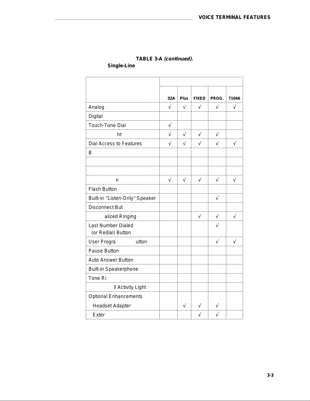
aaaaaaaaaaaaaaaaaaaaaaaaaaaaaaaaaaaaaaaaaaaaaaaaaaaaaaaaa
VOICE TERMINAL FEATURES
TABLE 3-A
(continued).
Single-Line (and 7401) Voice Terminal Features
bbbbbbbbbbbbbbbbbbbbbbbbbbbbbbbbbbbbbbbbbbbbbbbbbbbbbbbbbbbbbbbbb
c
c
c
c
PHYSICAL FEATURES 7102A Plus FIXED PROG. 7104A
bbbbbbbbbbbbbbbbbbbbbbbbbbbbbbbbbbbbbbbbbbbbbbbbbbbbbbbbbbbbbbbbb
c
c
Analog √√√ √ √
bbbbbbbbbbbbbbbbbbbbbbbbbbbbbbbbbbbbbbbbbbbbbbbbbbbbbbbbbbbbbbbbb
c
c
Digital
bbbbbbbbbbbbbbbbbbbbbbbbbbbbbbbbbbbbbbbbbbbbbbbbbbbbbbbbbbbbbbbbb
c
Touch-Tone Dial √√√ √ √
c
bbbbbbbbbbbbbbbbbbbbbbbbbbbbbbbbbbbbbbbbbbbbbbbbbbbbbbbbbbbbbbbbb
c
Message Light √√√ √
c
bbbbbbbbbbbbbbbbbbbbbbbbbbbbbbbbbbbbbbbbbbbbbbbbbbbbbbbbbbbbbbbbb
c
Dial Access to Features √√√ √ √
bbbbbbbbbbbbbbbbbbbbbbbbbbbbbbbbbbbbbbbbbbbbbbbbbbbbbbbbbbbbbbbbb
c
c
Built-in Digital Display √
bbbbbbbbbbbbbbbbbbbbbbbbbbbbbbbbbbbbbbbbbbbbbbbbbbbbbbbbbbbbbbbbb
c
c
Feature-only Buttons 8 10 16
bbbbbbbbbbbbbbbbbbbbbbbbbbbbbbbbbbbbbbbbbbbbbbbbbbbbbbbbbbbbbbbbb
c
Hold Button
c
bbbbbbbbbbbbbbbbbbbbbbbbbbbbbbbbbbbbbbbbbbbbbbbbbbbbbbbbbbbbbbbbb
c
Recall Button √√√ √ √
c
bbbbbbbbbbbbbbbbbbbbbbbbbbbbbbbbbbbbbbbbbbbbbbbbbbbbbbbbbbbbbbbbb
c
Flash Button
bbbbbbbbbbbbbbbbbbbbbbbbbbbbbbbbbbbbbbbbbbbbbbbbbbbbbbbbbbbbbbbbb
c
c
Built-in ‘‘Listen-Only’’ Speaker √
bbbbbbbbbbbbbbbbbbbbbbbbbbbbbbbbbbbbbbbbbbbbbbbbbbbbbbbbbbbbbbbbb
c
Disconnect Button √√
c
bbbbbbbbbbbbbbbbbbbbbbbbbbbbbbbbbbbbbbbbbbbbbbbbbbbbbbbbbbbbbbbbb
c
Personalized Ringing √√√
c
bbbbbbbbbbbbbbbbbbbbbbbbbbbbbbbbbbbbbbbbbbbbbbbbbbbbbbbbbbbbbbbbb
c
Last Number Dialed √
c
(or Redial) Button
c
bbbbbbbbbbbbbbbbbbbbbbbbbbbbbbbbbbbbbbbbbbbbbbbbbbbbbbbbbbbbbbbbb
c
User Programming Button √√
c
bbbbbbbbbbbbbbbbbbbbbbbbbbbbbbbbbbbbbbbbbbbbbbbbbbbbbbbbbbbbbbbbb
c
Pause Button
bbbbbbbbbbbbbbbbbbbbbbbbbbbbbbbbbbbbbbbbbbbbbbbbbbbbbbbbbbbbbbbbb
c
c
Auto Answer Button
bbbbbbbbbbbbbbbbbbbbbbbbbbbbbbbbbbbbbbbbbbbbbbbbbbbbbbbbbbbbbbbbb
c
c
Built-in Speakerphone
bbbbbbbbbbbbbbbbbbbbbbbbbbbbbbbbbbbbbbbbbbbbbbbbbbbbbbbbbbbbbbbbb
c
Tone Ringing √√√ √ √
c
bbbbbbbbbbbbbbbbbbbbbbbbbbbbbbbbbbbbbbbbbbbbbbbbbbbbbbbbbbbbbbbbb
c
Feature/Call Activity Light
c
bbbbbbbbbbbbbbbbbbbbbbbbbbbbbbbbbbbbbbbbbbbbbbbbbbbbbbbbbbbbbbbbb
c
Optional Enhancements
c
c
Headset Adapter √√ √
bbbbbbbbbbbbbbbbbbbbbbbbbbbbbbbbbbbbbbbbbbbbbbbbbbbbbbbbbbbbbbbbb
c
c
External Speakerphone √√ √
bbbbbbbbbbbbbbbbbbbbbbbbbbbbbbbbbbbbbbbbbbbbbbbbbbbbbbbbbbbbbbbbbc
c
bbbbbbbbbbbbbbbbbbbbbbbbbbbbbbbbbbb
c
c
7102 7103A 7103A
c
c
c
c
c
c
c
c
c
c
c
c
c
c
c
c
c
c
c
c
c
c
c
c
c
c
c
c
c
c
c
c
c
c
c
c
c
c
c
c
c
c
c
c
c
VOICE TERMINALS
c
c
c
c
c
c
c
c
c
c
c
c
c
c
c
c
c
c
c
c
c
c
c
c
c
c
c
c
c
c
c
c
c
c
c
c
c
c
c
c
c
c
c
c
c
c
c
c
c
c
c
c
c
c
c
c
c
c
c
c
c
c
c
c
c
c
c
c
c
c
c
c
c
c
c
c
c
c
c
c
c
c
c
c
c
c
c
c
c
c
c
c
c
c
c
c
c
c
c
c
c
c
c
c
c
c
c
c
c
c
c
c
c
c
c
c
c
c
c
c
c
c
c
c
c
c
c
c
c
c
c
c
c
c
c
c
c
c
c
c
c
c
c
c
c
c
c
c
c
c
c
c
c
c
c
c
c
c
c
c
c
c
c
c
c
c
c
c
c
c
c
c
c
c
c
c
c
c
c
c
c
c
c
c
c
c
c
c
c
c
c
c
c
c
c
c
c
c
c
c
c
c
c
c
c
c
c
c
c
c
c
c
c
c
c
c
c
c
c
c
c
c
c
c
c
c
c
c
c
c
c
c
3-3
Page 94
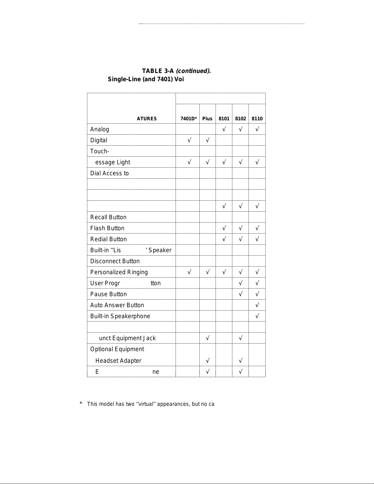
VOICE TERMINAL FEATURES
aaaaaaaaaaaaaaaaaaaaaaaaaaaaaaaaaaaaaaaaaaaaaaaa
TABLE 3-A
(continued).
Single-Line (and 7401) Voice Terminal Features
bbbbbbbbbbbbbbbbbbbbbbbbbbbbbbbbbbbbbbbbbbbbbbbbbbbbbbbbbbbbb
c
c
c
c
PHYSICAL FEATURES 7401D* Plus 8101 8102 8110
bbbbbbbbbbbbbbbbbbbbbbbbbbbbbbbbbbbbbbbbbbbbbbbbbbbbbbbbbbbbb
c
c
Analog √√√
bbbbbbbbbbbbbbbbbbbbbbbbbbbbbbbbbbbbbbbbbbbbbbbbbbbbbbbbbbbbb
c
c
Digital √√
bbbbbbbbbbbbbbbbbbbbbbbbbbbbbbbbbbbbbbbbbbbbbbbbbbbbbbbbbbbbb
c
Touch-Tone Dial √√√√√
c
bbbbbbbbbbbbbbbbbbbbbbbbbbbbbbbbbbbbbbbbbbbbbbbbbbbbbbbbbbbbb
c
Message Light √√√√√
c
bbbbbbbbbbbbbbbbbbbbbbbbbbbbbbbbbbbbbbbbbbbbbbbbbbbbbbbbbbbbb
c
Dial Access to Features √√√√√
bbbbbbbbbbbbbbbbbbbbbbbbbbbbbbbbbbbbbbbbbbbbbbbbbbbbbbbbbbbbb
c
c
Built-in Digital Display
bbbbbbbbbbbbbbbbbbbbbbbbbbbbbbbbbbbbbbbbbbbbbbbbbbbbbbbbbbbbb
c
c
Feature-only Buttons
bbbbbbbbbbbbbbbbbbbbbbbbbbbbbbbbbbbbbbbbbbbbbbbbbbbbbbbbbbbbb
c
Hold Button √√√
c
bbbbbbbbbbbbbbbbbbbbbbbbbbbbbbbbbbbbbbbbbbbbbbbbbbbbbbbbbbbbb
c
Recall Button
c
bbbbbbbbbbbbbbbbbbbbbbbbbbbbbbbbbbbbbbbbbbbbbbbbbbbbbbbbbbbbb
c
Flash Button √√√
bbbbbbbbbbbbbbbbbbbbbbbbbbbbbbbbbbbbbbbbbbbbbbbbbbbbbbbbbbbbb
c
c
Redial Button √√√
bbbbbbbbbbbbbbbbbbbbbbbbbbbbbbbbbbbbbbbbbbbbbbbbbbbbbbbbbbbbb
c
Built-in ‘‘Listen-Only’’ Speaker
c
bbbbbbbbbbbbbbbbbbbbbbbbbbbbbbbbbbbbbbbbbbbbbbbbbbbbbbbbbbbbb
c
Disconnect Button
c
bbbbbbbbbbbbbbbbbbbbbbbbbbbbbbbbbbbbbbbbbbbbbbbbbbbbbbbbbbbbb
c
Personalized Ringing √√√√√
bbbbbbbbbbbbbbbbbbbbbbbbbbbbbbbbbbbbbbbbbbbbbbbbbbbbbbbbbbbbb
c
c
User Programming Button √√
bbbbbbbbbbbbbbbbbbbbbbbbbbbbbbbbbbbbbbbbbbbbbbbbbbbbbbbbbbbbb
c
c
Pause Button √√
bbbbbbbbbbbbbbbbbbbbbbbbbbbbbbbbbbbbbbbbbbbbbbbbbbbbbbbbbbbbb
c
Auto Answer Button √
c
bbbbbbbbbbbbbbbbbbbbbbbbbbbbbbbbbbbbbbbbbbbbbbbbbbbbbbbbbbbbb
c
Built-in Speakerphone √
c
bbbbbbbbbbbbbbbbbbbbbbbbbbbbbbbbbbbbbbbbbbbbbbbbbbbbbbbbbbbbb
c
Tone Ringing √√√√√
bbbbbbbbbbbbbbbbbbbbbbbbbbbbbbbbbbbbbbbbbbbbbbbbbbbbbbbbbbbbb
c
c
Adjunct Equipment Jack √√
bbbbbbbbbbbbbbbbbbbbbbbbbbbbbbbbbbbbbbbbbbbbbbbbbbbbbbbbbbbbb
c
c
Optional Equipment
c
Headset Adapter √√
c
bbbbbbbbbbbbbbbbbbbbbbbbbbbbbbbbbbbbbbbbbbbbbbbbbbbbbbbbbbbbb
c
External Speakerphone √√
c
bbbbbbbbbbbbbbbbbbbbbbbbbbbbbbbbbbbbbbbbbbbbbbbbbbbbbbbbbbbbbc
c
bbbbbbbbbbbbbbbbbbbbbbbbbbbbbbb
c
c
c
c
c
c
c
c
c
c
c
c
c
c
c
c
c
c
c
c
c
c
c
c
c
c
c
c
c
c
c
c
c
c
c
c
c
c
c
c
c
c
c
c
c
c
VOICE TERMINALS
c
c
c
7401
c
c
c
c
c
c
c
c
c
c
c
c
c
c
c
c
c
c
c
c
c
c
c
c
c
c
c
c
c
c
c
c
c
c
c
c
c
c
c
c
c
c
c
c
c
c
c
c
c
c
c
c
c
c
c
c
c
c
c
c
c
c
c
c
c
c
c
c
c
c
c
c
c
c
c
c
c
c
c
c
c
c
c
c
c
c
c
c
c
c
c
c
c
c
c
c
c
c
c
c
c
c
c
c
c
c
c
c
c
c
c
c
c
c
c
c
c
c
c
c
c
c
c
c
c
c
c
c
c
c
c
c
c
c
c
c
c
c
c
c
c
c
c
c
c
c
c
c
c
c
c
c
c
c
c
c
c
c
c
c
c
c
c
c
c
c
c
c
c
c
c
c
c
c
c
c
c
c
c
c
c
c
c
c
c
c
c
c
c
c
c
c
c
c
c
c
c
c
c
c
c
c
c
c
c
c
c
c
c
c
c
c
c
c
c
c
c
c
c
c
c
c
c
c
3-4
* This model has two ‘‘virtual’’ appearances, but no call appearance buttons.
Page 95
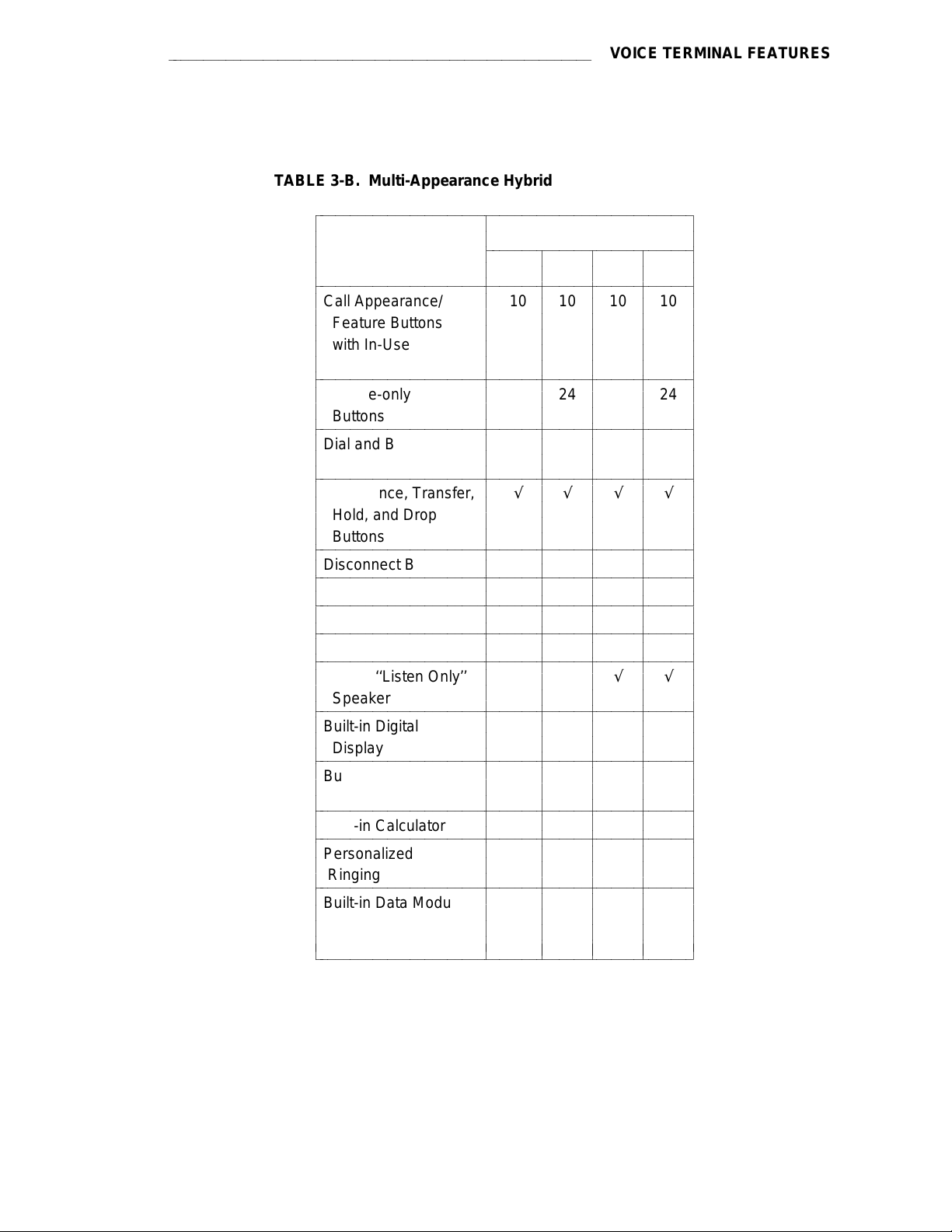
aaaaaaaaaaaaaaaaaaaaaaaaaaaaaaaaaaaaaaaaaaaaaaaaaaaaaaaaa
TABLE 3-B. Multi-Appearance Hybrid Voice Terminal Features
bbbbbbbbbbbbbbbbbbbbbbbbbbbbbbbbbbbbbbbbbbbbbbbbbbb
c
c
c
c
bbbbbbbbbbbbbbbbbbbbbbbbbbbbbbbbbbbbbbbbbbbbbbbbbbb
c
c
c
c
c
c
bbbbbbbbbbbbbbbbbbbbbbbbbbbbbbbbbbbbbbbbbbbbbbbbbbb
c
c
c
bbbbbbbbbbbbbbbbbbbbbbbbbbbbbbbbbbbbbbbbbbbbbbbbbbb
c
c
c
bbbbbbbbbbbbbbbbbbbbbbbbbbbbbbbbbbbbbbbbbbbbbbbbbbb
c
c
c
c
c
bbbbbbbbbbbbbbbbbbbbbbbbbbbbbbbbbbbbbbbbbbbbbbbbbbb
c
c
bbbbbbbbbbbbbbbbbbbbbbbbbbbbbbbbbbbbbbbbbbbbbbbbbbb
c
bbbbbbbbbbbbbbbbbbbbbbbbbbbbbbbbbbbbbbbbbbbbbbbbbbb
c
c
bbbbbbbbbbbbbbbbbbbbbbbbbbbbbbbbbbbbbbbbbbbbbbbbbbb
c
c
bbbbbbbbbbbbbbbbbbbbbbbbbbbbbbbbbbbbbbbbbbbbbbbbbbb
c
c
c
bbbbbbbbbbbbbbbbbbbbbbbbbbbbbbbbbbbbbbbbbbbbbbbbbbb
c
c
c
bbbbbbbbbbbbbbbbbbbbbbbbbbbbbbbbbbbbbbbbbbbbbbbbbbb
c
c
c
bbbbbbbbbbbbbbbbbbbbbbbbbbbbbbbbbbbbbbbbbbbbbbbbbbb
c
c
bbbbbbbbbbbbbbbbbbbbbbbbbbbbbbbbbbbbbbbbbbbbbbbbbbb
c
c
c
bbbbbbbbbbbbbbbbbbbbbbbbbbbbbbbbbbbbbbbbbbbbbbbbbbb
c
c
c
c
c
bbbbbbbbbbbbbbbbbbbbbbbbbbbbbbbbbbbbbbbbbbbbbbbbbbbc
PHYSICAL
FEATURES 7203H 7205H 7303S 7305S
Call Appearance/ 10 10 10 10
Feature Buttons
with In-Use and
Status Lights
Feature-only 24 24
Buttons
Dial and Buttons √√√√
Access to Features
Conference, Transfer, √√√√
Hold, and Drop
Buttons
Disconnect Button √√
Recall Button √√√√
Self-Test Switch √√
Message Light √√√√
Built-in ‘‘Listen Only’’ √√
Speaker
Built-in Digital
Display
Built-in
Speakerphone
Built-in Calculator
Personalized
Ringing
Built-in Data Module
and Data Call in
Progress Light
c
c
bbbbbbbbbbbbbbbbbbbbbbbbbbbb
c
c
c
c
c
c
c
c
c
c
c
c
c
c
c
c
c
c
c
c
c
c
c
c
c
c
c
c
c
c
c
c
c
c
c
c
c
c
c
c
c
c
c
c
c
c
VOICE TERMINALS
c
c
c
c
c
c
c
c
c
c
c
c
c
c
c
c
c
c
c
c
c
c
c
c
c
c
c
c
c
c
c
c
c
c
c
c
c
c
c
c
c
c
c
c
c
c
VOICE TERMINAL FEATURES
c
c
c
c
c
c
c
c
c
c
c
c
c
c
c
c
c
c
c
c
c
c
c
c
c
c
c
c
c
c
c
c
c
c
c
c
c
c
c
c
c
c
c
c
c
c
c
c
c
c
c
c
c
c
c
c
c
c
c
c
c
c
c
c
c
c
c
c
c
c
c
c
c
c
c
c
c
c
c
c
c
c
c
c
c
c
c
c
c
c
c
c
c
c
c
c
c
c
c
c
c
c
c
c
c
c
c
c
c
c
c
c
c
c
c
c
c
c
c
c
c
c
c
c
c
c
c
c
c
c
c
c
c
c
c
c
c
c
c
c
3-5
Page 96

VOICE TERMINAL FEATURES
aaaaaaaaaaaaaaaaaaaaaaaaaaaaaaaaaaaaaaaaaaaaaaaa
TABLE 3-B
(continued).
Multi-Appearance Hybrid Voice Terminal Features
bbbbbbbbbbbbbbbbbbbbbbbbbbbbbbbbbbbbbbbbbbbbbbbbbbbbbb
c
c
c
c
bbbbbbbbbbbbbbbbbbbbbbbbbbbbbbbbbbbbbbbbbbbbbbbbbbbbbb
c
AC Powered
c
bbbbbbbbbbbbbbbbbbbbbbbbbbbbbbbbbbbbbbbbbbbbbbbbbbbbbb
c
DC Powered √√√√
c
bbbbbbbbbbbbbbbbbbbbbbbbbbbbbbbbbbbbbbbbbbbbbbbbbbbbbb
c
Optional Enhancements
c
c
Headset Adapter √√√√
bbbbbbbbbbbbbbbbbbbbbbbbbbbbbbbbbbbbbbbbbbbbbbbbbbbbbb
c
c
External Speakerphone √√√√
bbbbbbbbbbbbbbbbbbbbbbbbbbbbbbbbbbbbbbbbbbbbbbbbbbbbbb
c
Digital Terminal
c
c
Data Module
bbbbbbbbbbbbbbbbbbbbbbbbbbbbbbbbbbbbbbbbbbbbbbbbbbbbbb
c
c
Data Module Base
bbbbbbbbbbbbbbbbbbbbbbbbbbbbbbbbbbbbbbbbbbbbbbbbbbbbbb
c
Call Coverage Module √
c
bbbbbbbbbbbbbbbbbbbbbbbbbbbbbbbbbbbbbbbbbbbbbbbbbbbbbb
c
Function Key Module √
c
bbbbbbbbbbbbbbbbbbbbbbbbbbbbbbbbbbbbbbbbbbbbbbbbbbbbbb
c
Digital Display Module
bbbbbbbbbbbbbbbbbbbbbbbbbbbbbbbbbbbbbbbbbbbbbbbbbbbbbb
c
c
Messaging Cartridge
bbbbbbbbbbbbbbbbbbbbbbbbbbbbbbbbbbbbbbbbbbbbbbbbbbbbbbc
PHYSICAL
FEATURES 7203H 7205H 7303S 7305S
c
c
bbbbbbbbbbbbbbbbbbbbbbbbbbbb
c
c
c
c
c
c
c
c
c
c
c
c
c
c
c
c
c
c
c
c
c
c
c
c
VOICE TERMINALS
c
c
c
c
c
c
c
c
c
c
c
c
c
c
c
c
c
c
c
c
c
c
c
c
c
c
c
c
c
c
c
c
c
c
c
c
c
c
c
c
c
c
c
c
c
c
c
c
c
c
c
c
c
c
c
c
c
c
c
c
c
c
c
c
c
c
c
c
c
c
c
c
c
c
c
c
c
c
c
c
c
c
c
c
c
c
c
c
c
c
c
c
c
c
c
c
c
c
3-6
Page 97

aaaaaaaaaaaaaaaaaaaaaaaaaaaaaaaaaaaaaaaaaaaaaaaaaaaaaaaaa
TABLE 3-C. Multi-Appearance Digital Voice Terminal Features
bbbbbbbbbbbbbbbbbbbbbbbbbbbbbbbbbbbbbbbbbbbbbbbbbbbbbbbbbbbbbbbbbbbbbbbbbbbb
c
c
c
c
bbbbbbbbbbbbbbbbbbbbbbbbbbbbbbbbbbbbbbbbbbbbbbbbbbbbbbbbbbbbbbbbbbbbbbbbbbbb
c
c
c
bbbbbbbbbbbbbbbbbbbbbbbbbbbbbbbbbbbbbbbbbbbbbbbbbbbbbbbbbbbbbbbbbbbbbbbbbbbb
c
c
c
bbbbbbbbbbbbbbbbbbbbbbbbbbbbbbbbbbbbbbbbbbbbbbbbbbbbbbbbbbbbbbbbbbbbbbbbbbbb
c
c
c
c
bbbbbbbbbbbbbbbbbbbbbbbbbbbbbbbbbbbbbbbbbbbbbbbbbbbbbbbbbbbbbbbbbbbbbbbbbbbb
c
c
c
bbbbbbbbbbbbbbbbbbbbbbbbbbbbbbbbbbbbbbbbbbbbbbbbbbbbbbbbbbbbbbbbbbbbbbbbbbbb
c
c
c
c
bbbbbbbbbbbbbbbbbbbbbbbbbbbbbbbbbbbbbbbbbbbbbbbbbbbbbbbbbbbbbbbbbbbbbbbbbbbb
c
c
bbbbbbbbbbbbbbbbbbbbbbbbbbbbbbbbbbbbbbbbbbbbbbbbbbbbbbbbbbbbbbbbbbbbbbbbbbbb
c
c
bbbbbbbbbbbbbbbbbbbbbbbbbbbbbbbbbbbbbbbbbbbbbbbbbbbbbbbbbbbbbbbbbbbbbbbbbbbb
c
c
bbbbbbbbbbbbbbbbbbbbbbbbbbbbbbbbbbbbbbbbbbbbbbbbbbbbbbbbbbbbbbbbbbbbbbbbbbbb
c
c
c
bbbbbbbbbbbbbbbbbbbbbbbbbbbbbbbbbbbbbbbbbbbbbbbbbbbbbbbbbbbbbbbbbbbbbbbbbbbb
c
c
c
bbbbbbbbbbbbbbbbbbbbbbbbbbbbbbbbbbbbbbbbbbbbbbbbbbbbbbbbbbbbbbbbbbbbbbbbbbbb
c
c
bbbbbbbbbbbbbbbbbbbbbbbbbbbbbbbbbbbbbbbbbbbbbbbbbbbbbbbbbbbbbbbbbbbbbbbbbbbb
c
c
c
bbbbbbbbbbbbbbbbbbbbbbbbbbbbbbbbbbbbbbbbbbbbbbbbbbbbbbbbbbbbbbbbbbbbbbbbbbbb
c
c
c
bbbbbbbbbbbbbbbbbbbbbbbbbbbbbbbbbbbbbbbbbbbbbbbbbbbbbbbbbbbbbbbbbbbbbbbbbbbb
c
c
c
c
c
bbbbbbbbbbbbbbbbbbbbbbbbbbbbbbbbbbbbbbbbbbbbbbbbbbbbbbbbbbbbbbbbbbbbbbbbbbbbc
PHYSICAL
FEATURES 7402 Plus 7403D 7404D 7405D 7406D 7406BIS 7406 Plus
Call Appearance/ 6 10 6 10 5 5 5
Feature Buttons
Feature-Only 24 3 1
Buttons
Shiftable 8 8 9
Feature Buttons
Dial and Buttons √√√√√√√
Access to Features
Conference, Transfer, √√√√√√√
Hold, and Drop
Buttons
Disconnect Button √√
Self-Test Capability √√√√ √ √
Message Light √√√√√√√
Built-in √ √√√
Speakerphone (Note 1) (Note 1)
Reset Speakerphone √
Capability
Mute Button √√
Built-in Digital √√√
Display (Note 2) (Note 2) (Note 2)
Personalized √ √√√
Ringing
Built-in Data Module √
and Data Call in
Progress Light
c
c
bbbbbbbbbbbbbbbbbbbbbbbbbbbbbbbbbbbbbbbbbbbbbbbbbbbbbb
c
c
c
c
c
c
c
c
c
c
c
c
c
c
c
c
c
c
c
c
c
c
c
c
c
c
c
c
c
c
c
c
c
c
c
c
c
c
c
c
c
c
c
c
c
c
c
c
c
c
c
c
c
c
c
c
c
c
c
c
c
c
c
c
c
c
c
c
c
c
c
c
c
c
c
c
c
c
c
c
c
c
c
c
c
c
c
c
c
VOICE TERMINALS
c
c
c
c
c
c
c
c
c
c
c
c
c
c
c
c
c
c
c
c
c
c
c
c
c
c
c
c
c
c
c
c
c
c
c
c
c
c
c
c
c
c
c
c
c
c
c
c
c
c
c
c
c
c
c
c
c
c
c
c
c
c
c
c
c
c
c
c
c
c
c
c
c
c
c
c
c
c
c
c
c
c
c
c
c
c
c
c
VOICE TERMINAL FEATURES
c
c
c
c
c
c
c
c
c
c
c
c
c
c
c
c
c
c
c
c
c
c
c
c
c
c
c
c
c
c
c
c
c
c
c
c
c
c
c
c
c
c
c
c
c
c
c
c
c
c
c
c
c
c
c
c
c
c
c
c
c
c
c
c
c
c
c
c
c
c
c
c
c
c
c
c
c
c
c
c
c
c
c
c
c
c
c
c
c
c
c
c
c
c
c
c
c
c
c
c
c
c
c
c
c
c
c
c
c
c
c
c
c
c
c
c
c
c
c
c
c
c
c
c
c
c
c
c
c
c
c
c
c
c
c
c
c
c
c
c
c
c
c
c
c
c
c
c
c
c
c
c
c
c
c
c
c
c
c
c
c
c
c
c
c
c
c
c
c
c
c
c
c
c
c
c
c
c
c
Note 1. The 7402 Plus and 7406D01A —7406D04A voice terminals have a ‘‘listen-only’’
speaker.
Note 2. The following 7406 sets have built-in displays: 7406D01A, 7406D03A, 7406D05A,
and 7406D07A.
3-7
Page 98

VOICE TERMINAL FEATURES
aaaaaaaaaaaaaaaaaaaaaaaaaaaaaaaaaaaaaaaaaaaaaaaa
TABLE 3-C
(continued).
Multi-Appearance Digital Voice Terminal Features
bbbbbbbbbbbbbbbbbbbbbbbbbbbbbbbbbbbbbbbbbbbbbbbbbbbbbbbbbbbbbbbbbbbbbbbbbbbb
c
c
c
c
bbbbbbbbbbbbbbbbbbbbbbbbbbbbbbbbbbbbbbbbbbbbbbbbbbbbbbbbbbbbbbbbbbbbbbbbbbbb
c
AC Powered √
c
bbbbbbbbbbbbbbbbbbbbbbbbbbbbbbbbbbbbbbbbbbbbbbbbbbbbbbbbbbbbbbbbbbbbbbbbbbbb
c
DC Powered √√ √√√ √
c
c
(supplied by PBX)
bbbbbbbbbbbbbbbbbbbbbbbbbbbbbbbbbbbbbbbbbbbbbbbbbbbbbbbbbbbbbbbbbbbbbbbbbbbb
c
Optional Enhancements
c
c
Headset Adapter √√ √√√ √
c
bbbbbbbbbbbbbbbbbbbbbbbbbbbbbbbbbbbbbbbbbbbbbbbbbbbbbbbbbbbbbbbbbbbbbbbbbbbb
c
External Speakerphone √√ √√√ √
bbbbbbbbbbbbbbbbbbbbbbbbbbbbbbbbbbbbbbbbbbbbbbbbbbbbbbbbbbbbbbbbbbbbbbbbbbbb
c
c
Digital Terminal √√
c
Data Module
c
bbbbbbbbbbbbbbbbbbbbbbbbbbbbbbbbbbbbbbbbbbbbbbbbbbbbbbbbbbbbbbbbbbbbbbbbbbbb
c
Data Module Base √
bbbbbbbbbbbbbbbbbbbbbbbbbbbbbbbbbbbbbbbbbbbbbbbbbbbbbbbbbbbbbbbbbbbbbbbbbbbb
c
c
Call Coverage Module √
bbbbbbbbbbbbbbbbbbbbbbbbbbbbbbbbbbbbbbbbbbbbbbbbbbbbbbbbbbbbbbbbbbbbbbbbbbbb
c
c
Function Key Module √
bbbbbbbbbbbbbbbbbbbbbbbbbbbbbbbbbbbbbbbbbbbbbbbbbbbbbbbbbbbbbbbbbbbbbbbbbbbb
c
Digital Display Module √
c
bbbbbbbbbbbbbbbbbbbbbbbbbbbbbbbbbbbbbbbbbbbbbbbbbbbbbbbbbbbbbbbbbbbbbbbbbbbb
c
Messaging Cartridge √
c
bbbbbbbbbbbbbbbbbbbbbbbbbbbbbbbbbbbbbbbbbbbbbbbbbbbbbbbbbbbbbbbbbbbbbbbbbbbb
c
7400B+ Data Module √ √√√√ √ √
bbbbbbbbbbbbbbbbbbbbbbbbbbbbbbbbbbbbbbbbbbbbbbbbbbbbbbbbbbbbbbbbbbbbbbbbbbbbc
PHYSICAL
FEATURES 7402 Plus 7403D 7404D 7405D 7406D 7406BIS 7406 Plus
c
c
bbbbbbbbbbbbbbbbbbbbbbbbbbbbbbbbbbbbbbbbbbbbbbbbbb
c
c
c
c
c
c
c
c
c
c
c
c
c
c
c
c
c
c
c
c
c
c
c
c
c
c
c
c
c
c
c
c
c
c
c
c
c
c
c
c
c
c
c
c
c
c
c
c
c
c
c
c
c
c
VOICE TERMINALS
c
c
c
c
c
c
c
c
c
c
c
c
c
c
c
c
c
c
c
c
c
c
c
c
c
c
c
c
c
c
c
c
c
c
c
c
c
c
c
c
c
c
c
c
c
c
c
c
c
c
c
c
c
c
c
c
c
c
c
c
c
c
c
c
c
c
c
c
c
c
c
c
c
c
c
c
c
c
c
c
c
c
c
c
c
c
c
c
c
c
c
c
c
c
c
c
c
c
c
c
c
c
c
c
c
c
c
c
c
c
c
c
c
c
c
c
c
c
c
c
c
c
c
c
c
c
c
c
c
c
c
c
c
c
c
c
c
c
c
c
c
c
c
c
c
c
c
c
c
c
c
c
c
c
c
c
c
c
c
c
c
c
c
c
3-8
Page 99

aaaaaaaaaaaaaaaaaaaaaaaaaaaaaaaaaaaaaaaaaaaaaaaaaaaaaaaaa
VOICE TERMINAL FEATURES
TABLE 3-C
(continued).
Multi-Appearance Digital Voice Terminal Features
bbbbbbbbbbbbbbbbbbbbbbbbbbbbbbbbbbbbbbbbbbbbbbbbbbbbbbbbbbbbbbbbbbbbbbbbb
c
c
c
c
bbbbbbbbbbbbbbbbbbbbbbbbbbbbbbbbbbbbbbbbbbbbbbbbbbbbbbbbbbbbbbbbbbbbbbbbb
c
c
c
bbbbbbbbbbbbbbbbbbbbbbbbbbbbbbbbbbbbbbbbbbbbbbbbbbbbbbbbbbbbbbbbbbbbbbbbb
c
c
c
bbbbbbbbbbbbbbbbbbbbbbbbbbbbbbbbbbbbbbbbbbbbbbbbbbbbbbbbbbbbbbbbbbbbbbbbb
c
c
c
c
bbbbbbbbbbbbbbbbbbbbbbbbbbbbbbbbbbbbbbbbbbbbbbbbbbbbbbbbbbbbbbbbbbbbbbbbb
c
c
c
bbbbbbbbbbbbbbbbbbbbbbbbbbbbbbbbbbbbbbbbbbbbbbbbbbbbbbbbbbbbbbbbbbbbbbbbb
c
c
c
bbbbbbbbbbbbbbbbbbbbbbbbbbbbbbbbbbbbbbbbbbbbbbbbbbbbbbbbbbbbbbbbbbbbbbbbb
c
c
c
c
bbbbbbbbbbbbbbbbbbbbbbbbbbbbbbbbbbbbbbbbbbbbbbbbbbbbbbbbbbbbbbbbbbbbbbbbb
c
c
bbbbbbbbbbbbbbbbbbbbbbbbbbbbbbbbbbbbbbbbbbbbbbbbbbbbbbbbbbbbbbbbbbbbbbbbb
c
c
bbbbbbbbbbbbbbbbbbbbbbbbbbbbbbbbbbbbbbbbbbbbbbbbbbbbbbbbbbbbbbbbbbbbbbbbb
c
c
c
bbbbbbbbbbbbbbbbbbbbbbbbbbbbbbbbbbbbbbbbbbbbbbbbbbbbbbbbbbbbbbbbbbbbbbbbb
c
c
c
bbbbbbbbbbbbbbbbbbbbbbbbbbbbbbbbbbbbbbbbbbbbbbbbbbbbbbbbbbbbbbbbbbbbbbbbb
c
c
bbbbbbbbbbbbbbbbbbbbbbbbbbbbbbbbbbbbbbbbbbbbbbbbbbbbbbbbbbbbbbbbbbbbbbbbb
c
c
c
bbbbbbbbbbbbbbbbbbbbbbbbbbbbbbbbbbbbbbbbbbbbbbbbbbbbbbbbbbbbbbbbbbbbbbbbb
c
c
c
bbbbbbbbbbbbbbbbbbbbbbbbbbbbbbbbbbbbbbbbbbbbbbbbbbbbbbbbbbbbbbbbbbbbbbbbbc
PHYSICAL
FEATURES 7407 Enhd 7407 7407 Plus 7410 7410 Plus 7434D 7444
Call Appearance/ 10 10 10 10 10 34 34
Feature Buttons
Feature-only 11 24 24
Buttons
Dual-Function 11
Feature Buttons
Display Control 7 7 7
Buttons
Dial and Buttons √ √ √√√ √√
Access to Features
Conference, Transfer, √ √ √√√ √√
Hold, and Drop
Buttons
Self-Test Capability √ √ √√√ √√
Message Light √ √ √√√ √√
Built-in √√ √ √ √
Speakerphone (Note 3)
Reset Speakerphone √√
Capability
Mute Button √√ √
Built-in Digital √√ √ √
Display
Personalized √ √ √√√ √√
Ringing
c
c
bbbbbbbbbbbbbbbbbbbbbbbbbbbbbbbbbbbbbbbbbbbbbbbbbb
c
c
c
c
c
c
c
c
c
c
c
c
c
c
c
c
c
c
c
c
c
c
c
c
c
c
c
c
c
c
c
c
c
c
c
c
c
c
c
c
c
c
c
c
c
c
c
c
c
c
c
c
c
c
c
c
c
c
c
c
c
c
c
c
c
c
c
c
c
c
c
c
c
c
c
c
c
c
c
c
c
c
VOICE TERMINALS
c
c
c
c
c
c
c
c
c
c
c
c
c
c
c
c
c
c
c
c
c
c
c
c
c
c
c
c
c
c
c
c
c
c
c
c
c
c
c
c
c
c
c
c
c
c
c
c
c
c
c
c
c
c
c
c
c
c
c
c
c
c
c
c
c
c
c
c
c
c
c
c
c
c
c
c
c
c
c
c
c
c
c
c
c
c
c
c
c
c
c
c
c
c
c
c
c
c
c
c
c
c
c
c
c
c
c
c
c
c
c
c
c
c
c
c
c
c
c
c
c
c
c
c
c
c
c
c
c
c
c
c
c
c
c
c
c
c
c
c
c
c
c
c
c
c
c
c
c
c
c
c
c
c
c
c
c
c
c
c
c
c
c
c
c
c
c
c
c
c
c
c
c
c
c
c
c
c
c
c
c
c
c
c
c
c
c
c
c
c
c
c
c
c
c
c
c
c
c
c
c
c
c
c
c
c
c
c
c
c
c
c
c
c
c
c
c
c
c
c
c
c
c
c
c
c
c
c
c
c
c
c
c
c
c
c
c
c
c
c
c
c
c
c
c
c
c
c
Note 3. The 7410D02A voice terminal has a ‘‘listen-only’’ speaker.
3-9
Page 100
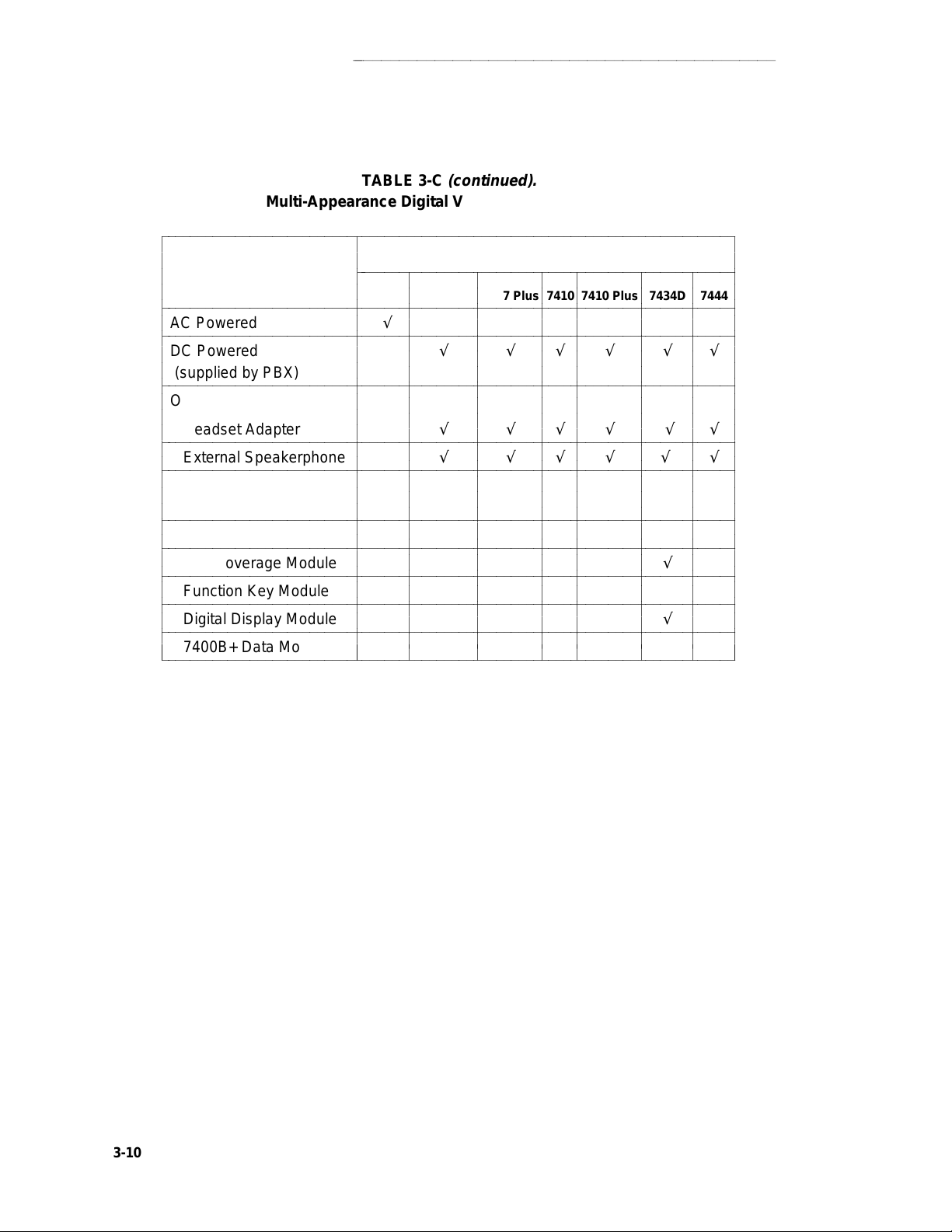
VOICE TERMINAL FEATURES
aaaaaaaaaaaaaaaaaaaaaaaaaaaaaaaaaaaaaaaaaaaaaaaa
TABLE 3-C
(continued).
Multi-Appearance Digital Voice Terminal Features
bbbbbbbbbbbbbbbbbbbbbbbbbbbbbbbbbbbbbbbbbbbbbbbbbbbbbbbbbbbbbbbbbbbbbbbbbbbbb
c
c
c
c
bbbbbbbbbbbbbbbbbbbbbbbbbbbbbbbbbbbbbbbbbbbbbbbbbbbbbbbbbbbbbbbbbbbbbbbbbbbbb
c
AC Powered √
c
bbbbbbbbbbbbbbbbbbbbbbbbbbbbbbbbbbbbbbbbbbbbbbbbbbbbbbbbbbbbbbbbbbbbbbbbbbbbb
c
DC Powered √√√√√√
c
c
(supplied by PBX)
bbbbbbbbbbbbbbbbbbbbbbbbbbbbbbbbbbbbbbbbbbbbbbbbbbbbbbbbbbbbbbbbbbbbbbbbbbbbb
c
Optional Enhancements
c
c
Headset Adapter √√√√√√
c
bbbbbbbbbbbbbbbbbbbbbbbbbbbbbbbbbbbbbbbbbbbbbbbbbbbbbbbbbbbbbbbbbbbbbbbbbbbbb
c
External Speakerphone √√√√√√
bbbbbbbbbbbbbbbbbbbbbbbbbbbbbbbbbbbbbbbbbbbbbbbbbbbbbbbbbbbbbbbbbbbbbbbbbbbbb
c
c
Digital Terminal
c
Data Module
c
bbbbbbbbbbbbbbbbbbbbbbbbbbbbbbbbbbbbbbbbbbbbbbbbbbbbbbbbbbbbbbbbbbbbbbbbbbbbb
c
Data Module Base √
bbbbbbbbbbbbbbbbbbbbbbbbbbbbbbbbbbbbbbbbbbbbbbbbbbbbbbbbbbbbbbbbbbbbbbbbbbbbb
c
c
Call Coverage Module √
bbbbbbbbbbbbbbbbbbbbbbbbbbbbbbbbbbbbbbbbbbbbbbbbbbbbbbbbbbbbbbbbbbbbbbbbbbbbb
c
c
Function Key Module
bbbbbbbbbbbbbbbbbbbbbbbbbbbbbbbbbbbbbbbbbbbbbbbbbbbbbbbbbbbbbbbbbbbbbbbbbbbbb
c
Digital Display Module √
c
bbbbbbbbbbbbbbbbbbbbbbbbbbbbbbbbbbbbbbbbbbbbbbbbbbbbbbbbbbbbbbbbbbbbbbbbbbbbb
c
7400B+ Data Module √√ √√√√√
c
bbbbbbbbbbbbbbbbbbbbbbbbbbbbbbbbbbbbbbbbbbbbbbbbbbbbbbbbbbbbbbbbbbbbbbbbbbbbbc
PHYSICAL
FEATURES 7407D Enhd 7407 7407 Plus 7410 7410 Plus 7434D 7444
c
c
bbbbbbbbbbbbbbbbbbbbbbbbbbbbbbbbbbbbbbbbbbbbbbbbbbb
c
c
c
c
c
c
c
c
c
c
c
c
c
c
c
c
c
c
c
c
c
c
c
c
c
c
c
c
c
c
c
c
c
c
c
c
c
c
c
c
c
c
c
c
c
c
c
c
c
c
c
VOICE TERMINALS
c
c
c
c
c
c
c
c
c
c
c
c
c
c
c
c
c
c
c
c
c
c
c
c
c
c
c
c
c
c
c
c
c
c
c
c
c
c
c
c
c
c
c
c
c
c
c
c
c
c
c
c
c
c
c
c
c
c
c
c
c
c
c
c
c
c
c
c
c
c
c
c
c
c
c
c
c
c
c
c
c
c
c
c
c
c
c
c
c
c
c
c
c
c
c
c
c
c
c
c
c
c
c
c
c
c
c
c
c
c
c
c
c
c
c
c
c
c
c
c
c
c
c
c
c
c
c
c
c
c
c
c
c
c
c
c
c
c
c
c
c
c
c
c
c
c
c
c
c
c
c
c
c
3-10
 Loading...