

Page 1

AT&T
AT&T System 75
and System 75 XE
Wiring
Page 2

AT&T
AT&T System 75
and System 75 XE
Wiring
555-200-111
Issue 2, August 1989
Page 3

TO ORDER COPIES OF THIS MANUAL
Call:
AT&T Customer Information Center on 800-432-6600
In Canada Call 800-255-1242
Write:
AT&T Customer Information Center
2855 North Franklin Road
P.O. Box 19901
Indianapolis, Indiana 46219-1385
TO COMMENT ON THIS MANUAL
Call: The AT&T Document Development Organization
Hot Line:
800-334-0404
In North Carolina Call 919-727-3167
While reasonable efforts were made to ensure that the information
in this document was complete and accurate at the time of printing,
AT&T can assume no responsibility for errors. Changes or
corrections to the information in this document may be incorporated
into future reissues.
Published by
The AT&T Documentation
Management Organization
Copyright© 1989 AT&T
All Rights Reserved
Printed in U.S.A.
Page 4

TABLE OF CONTENTS
Page
CHAPTER 1. INTRODUCTION
General
Organization
Use of Guide
Equipment
System Wiring
Cross-Connect Hardware Selection
Wiring Hardware Changes
Planning
Job Aids
Voice Terminals
Site or Satellite Closets
Cabling Facilities
CHAPTER 2. HARDWARE
(66/110-Type)
1-1
1-1
1-4
1-5
1-5
1-5
1-9
1-10
1-11
1-11
1-11
1-13
1-13
2-1
General
110-Type Hardware Description
110-Type Wiring Blocks
Index Strips and Connecting Blocks
110A-Type Hardware
110P-Type Hardware
188-Type Backboards
Cords
Jumpers
Tools
F Clip Terminal Insulator
Designation Strips
66-Type Hardware Description
66M1-50 Connecting Block
Connectorized 66-Type Connecting Blocks
Multiple-Mounted 66-Type Connecting Blocks
183-Type Backboards
187B1 Backboard
Power Adapter Cords
Jumpers
Tools
2-1
2-3
2-3
2-4
2-7
2-11
2-18
2-18
2-21
2-21
2-22
2-22
2-23
2-23
2-24
2-25
2-26
2-28
2-28
2-29
2-30
i
Page 5

TABLE OF CONTENTS (Contd)
Page
Bridging Clips
Associated Hardware
Cable Slack Managers
Network Interfaces
Sneak Fuse Panels
Emergency Transfer Units
Trunk Concentrator Cables
16-Port Analog Line Circuit Pack Adapter Cable (For 110-Type
Hardware Only)
4-Port Met Line Circuit Pack Concentrator Cable
Adjunct Power Units
CHAPTER 3. EQUIPMENT ROOM
DESIGN
General
Hardware Equipment Room Appplications
Trunk/Auxiliary Field
Distribution Field
2-30
2-31
2-31
2-34
2-34
2-37
2-39
2-45
2-46
2-47
3-1
3-1
3-1
3-1
3-4
Typical System Equipment Room Floor Plans
General
Typical Floor Plans
Wall Space Requirements
Equipment Requirements
Equipment Room Hardware And Cabling Installation
Hardware Installation
Installing Cable Slack Managers
Labeling the Cross-Connect Field
Installing Sneak Fuse Panels
Cable Installation
Station Wiring Design
General
Station Circuit Distribution From Equipment Room
Layout
3-13
3-13
3-13
3-20
3-21
3-25
3-25
3-32
3-32
3-63
3-64
3-90
3-90
3-98
3-107
ii
Page 6

TABLE OF CONTENTS (Contd)
Page
CHAPTER 4. STATION WIRING
Installation of Station Wiring And Associated Hardware
Installing Station Cables
Installing 110-Type Hardware at Satellite Locations
Installing 66-Type Hardware at Satellite Locations
Installing 4-Pair Station Cables
Installing Information Outlets
Adjunct Powering
Adjunct Powering From the Equipment Room and Satellite
Locations
Adjunct Powering From Site Locations
Adjunct Powering From Information Outlets
Patch Cord/Jumper Installation And Administration
Equipment Room Cross-Connect Field
Satellite Locations
Miscellaneous Wiring Installation
Installing System Access Terminal (SAT)
Installing Attendant Console
Installing Selector Console
Installing lNADS lnterface
Installing DS1 Tie Trunks
Installing Customer-Provided Alarm—System 75 XE Only
Installing Off-Premises Station Wiring
Installing Out-of-Building Station Wiring
Installing Emergency Transfer Units and Associated
Telephones
Installing External Ringing
Installing Queue Warning Indicator
4-1
4-1
4-1
4-4
4-9
4-10
4-10
4-12
4-12
4-14
4-16
4-18
4-20
4-23
4-24
4-24
4-25
4-30
4-31
4-33
4-36
4-36
4-37
4-45
4-67
4-68
CHAPTER 5. AUXILIARY
EQUIPMENT INSTALLATION
Auxiliary Equipment Description
Installing Loudspeaker Paging and Music-on-Hold
Installing Loudspeaker Paging Access—278A Paging Adapter
Installing Loudspeaker Paging Access—89A Control Unit
Installing PagePac® Paging System
Installing Music-on-Hold Access
Installing Loudspeaker Paging With Background Music
Installing Recorded Announcement Equipment
iii
5-1
5-1
5-3
5-5
5-8
5-11
5-16
5-20
5-22
Page 7

TABLE OF CONTENTS (Contd)
Page
Digital Announcer
Installing Audichron Wake-Up Announcement System—R1V3
Only
Installing Dial Dictation Equipment
Installing 3270 Data Modules
Installing Processor Data Modules (PDMs)
Installing AP Interface—System 75 Only
Installing AUDIX Interface—R1V3 Only
Installing CMS Interface—R1V3 Only
Installing DCS—R1V2 and R1V3
Installing PMS Interface—R1V3 Only
Installing Customer-Provided Terminal Using ADUs
Installing SMDR lnterface
Installing lSN lnterface
Installing STARLAN NETWORK Interface
Installing Premises Lightwave System (PLS) Interface
Installing Processor Interface/EIA Port
CHAPTER 6. GLOSSARY
5-26
5-28
5-32
5-33
5-36
5-39
5-42
5-42
5-43
5-44
5-45
5-45
5-49
5-52
5-53
5-55
6-1
CHAPTER 7. INDEX
7-1
iv
Page 8

CHAPTER 1. INTRODUCTION
GeneraI
Organization
Use of Guide
Equipment
System Wiring
Cross-Connect Hardware Selection
Wiring Hardware Changes
Planning
Job Aids
Voice Terminals
Site or Satellite Closets
Cabling Facilities
1-1
1-4
1-5
1-5
1-5
1-9
1-10
1-11
1-11
1-11
1-13
1-13
-i-
Page 9

Figures
Figure 1-1. Documentation Block Diagram
Figure 1-2.
Figure 1-3.
Figure 1-4. Block Diagram of System 75 or 75 XE Installation
Figure 1-5.
Figure 1-6.
System Uniform Wiring Plan
Sample Uniform Wiring Installation
Sample Floor Plan With Voice Terminal Locations
Marked
Riser Cable Placement
1-3
1-7
1-8
1-10
1-12
1-14
-ii-
Page 10

CHAPTER 1. INTRODUCTION
CHAPTER 1. INTRODUCTION
General
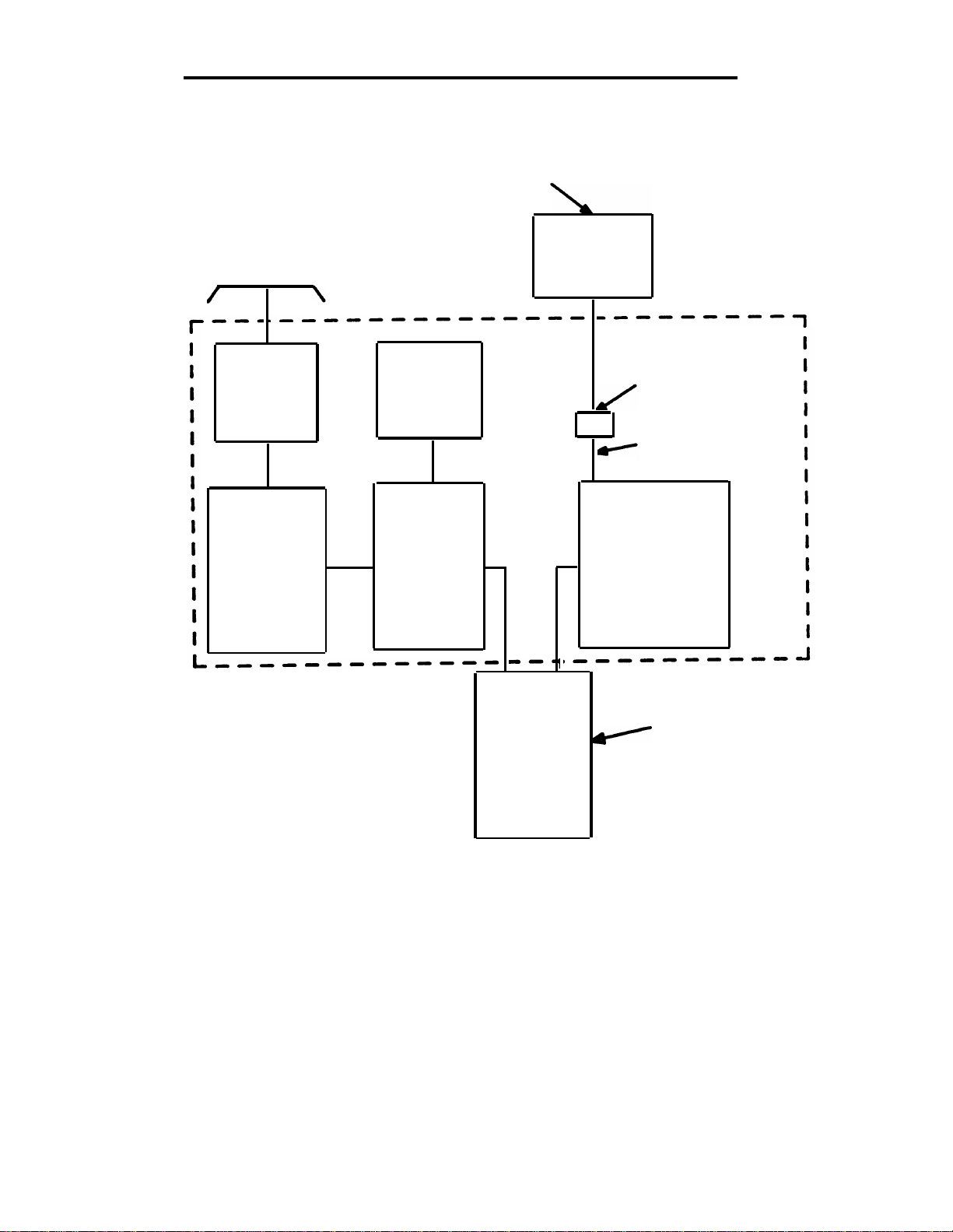
This guide is one of the three documents (Figure 1-1) required to install
a System 75 or 75 XE switch. This guide describes the hardware, job
planning, equipment ordering, and installation information from:
The telephone company network interface up to and including the
●
25-pair cables that connect directly to the switch
The main equipment room cross-connect field and the associated
●
cabling from this cross-connect field to the switch cabinet and/or
8-pin modular wall jacks (information outlets).
All information in this guide is compatible with both System 75 or 75 XE,
except when a statement is made that a topic is strictly for a specific
switch.
The other documents required for the installation of the System 75 or 75
XE are as follows:
AT&T System 75—Installation and Test (555-200-104):
Contains the information required to install and test a System 75
switch and attendant console. For continuity purposes, the
attendant console wiring is covered in this guide.
AT&T System 75— XE Installation and Test (555-201-104):
Contains the information required to install and test a System 75
XE switch and attendant console. For continuity purposes, the
attendant console wiring is covered in this guide.
DEFINITY™ Communications System and System 75, and
System 85—Terminals and Adjuncts, Installation and Tests
(555-015-104)
Contains the information required to install and test
telephones/voice terminals and their associated adjuncts.
1-1
Page 11

CHAPTER 1. INTRODUCTION
This issue replaces all previous issues of this document. The reason for
reissue is:
●
Remove information pertaining to Z100-type hardware.
●
Combine information for 66- and 110-type hardware.
●
Add processor/EIA interface connections.
●
Add digital out-of-building voice terminal connections.
●
Add connections for System Access Terminal (SAT).
1-2
Page 12
MANUAL
555-015-104
General
CENTRAL
OFFICE
TRUNKS
NETWORK
INTERFACE
SNEAK FUSE
PANEL
AUXILIARY
EQUIPMENT
TRUNK/
AUXILIARY
FIELD
TERMINALS
AND
ADJUNCTS
WIRING GUIDE
(555-200-111)
INFORMATION
OUTLET
STATION
WIRING
MAIN
CROSS-CONNECT
FIELD
MANUAL
SWITCH
CABINET
AND
CONSOLE
(555-200-104
OR
555-201-104)
Figure 1-1. Documentation Block Diagram
1-3
Page 13

CHAPTER 1. INTRODUCTION
Organization
This guide is organized into seven chapters:
●
CHAPTER 1—INTRODUCTION
Presents an overview of the system Uniform Wiring Plan,
general guidelines on hardware selection, and organization
of the guide.
●
CHAPTER 2—HARDWARE (66- and 110-Type)
Describes the 66- and 110-type connecting blocks and
associated hardware, job planning, equipment ordering
codes, and how to install the hardware.
●
CHAPTER 3—EQUIPMENT ROOM DESIGN
Describes hardware application in the equipment room,
labeling procedures, and grounding techniques.
●
CHAPTER 4—STATION WIRING
Describes station and miscellaneous wiring, adjunct
powering, and administration and installation of patch cords
and jumper wires.
●
CHAPTER 5—AUXILIARY EQUIPMENT
Provides connection information for the various types of
auxiliary equipment that can be used with the switch.
●
CHAPTER 6—GLOSSARY
Contains a brief description of some of the terms used in this
guide.
1-4
●
CHAPTER 7—INDEX
Contains a permuted index.
Page 14

Organization
Use of Guide
This guide provides information for planning, designing, and installing a
cost-effective wiring installation that allows moves, changes, and
additions to be made quickly and easily. To make the best use of this
guide, take the time to read it thoroughly and become familiar with its
contents and organization. For quick access to information needed to
answer most questions, refer to the table of contents and locate the
specific item in question.
To answer questions requiring more information than this guide
contains, consult the documents listed previously in this introduction
section. If you need additional help, contact the Premises Services
Consultant (PSC).
For further technical assistance, the recommended channel for AT&T
System Technicians is as follows:
1.
Contact your Field Assistance and Support Team (FAST).
If a satisfactory answer is not obtained from the FAST center,
2.
contact your supervisor.
Your supervisor should contact the regional staff, if necessary.
3.
Equipment
Most of the items specified in this guide are available through the local
AT&T Marketing Branch Office (MBO). However, some common use
hardware items may have to be obtained from other sources.
System Wiring
System wiring plays a significant role in customers’ information systems.
Technological innovations enable both voice and data transmission to
be provided through the system wiring. Also, the system wiring has
been simplified by reducing the number of cable pairs required by voice
terminals equipped with enhanced feature options.
This guide provides planning, ordering, and installation guidelines for a
system Uniform Wiring Plan (Figures 1-2 and 1-3) using 110-type or
66-type hardware.
1-5
Page 15

CHAPTER 1. INTRODUCTION
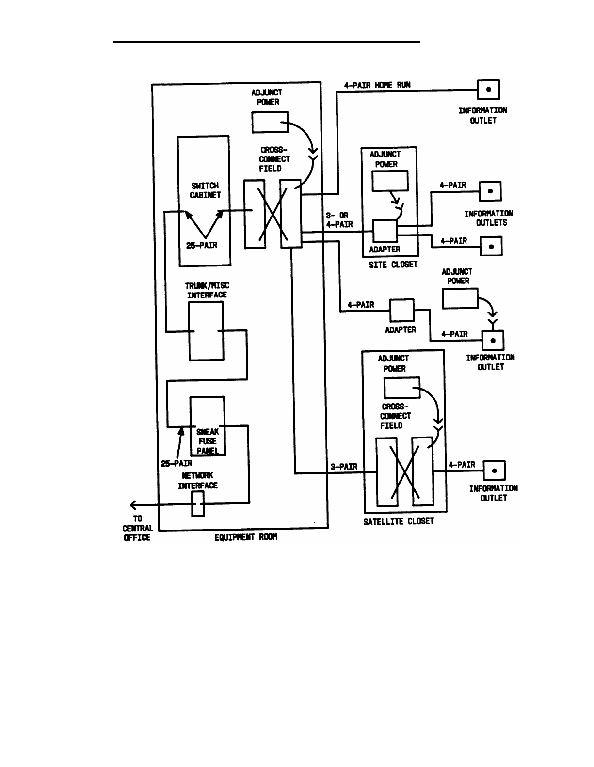
The system switch ports for data and voice terminals require three pairs
of wire per circuit. Voice terminal adjuncts require an additional pair for
remote powering. To provide maximum flexibility for voice terminal
changes, rearrangements, and powering, all data and voice terminal
information outlets are wired with 4-pair cable. With proper
administration, this will allow any voice terminal to be located at any
information outlet.
1-6
Page 16
System Wiring
Figure 1-2. System Uniform Wiring Plan
1-7
Page 17

CHAPTER 1. INTRODUCTION
1-8
Figure 1-3. Sample Uniform Wiring Installation
Page 18

Cross-Connect Hardware Selection
Cross-Connect Hardware Selection
For new wiring installations, the following cross-connect hardware is
available for use in the system. Each item lists certain considerations
that should help to select the appropriate hardware.
1. 110P Hardware
●
Patch cord design allows customer to administer
cross-connections
●
Requires some technical skill to administer cross-connections
2. 110A Hardware
●
Design does not permit customer participation in
cross-connect administration—requires technically skilled
personnel to administer cross-connections
●
Hardware is less expensive than the patch cord systems, but
installation and administrative costs are greater
3. 66-type Hardware
●
Design does not permit customer participation in
cross-connect administration—requires technically skilled
personnel to administer cross-connections
●
Hardware is less expensive than the patch cord systems, but
installation and administrative costs are greater
Obviously, the customer’s interest and preference for administering
cross-connections (because of likely lower total annual costs, as well as
the capability to administer the cross-connections at the most convenient
time) should be given primary consideration in recommending
cross-connect hardware.
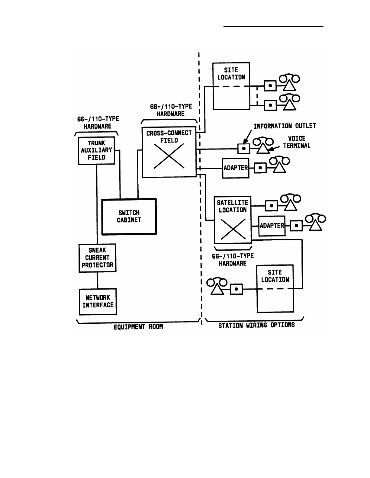
Figure 1-4 shows a block diagram of the equipment required to install a
System 75 or 75 XE switch. The sites shown in Figure 1-4 are physical
locations (closets) for pass-through connections where adjunct power
may be applied. The satellite is a physical location (closet) where
cross-connect administration can take place and adjunct power may be
applied.
1-9
Page 19

CHAPTER 1. INTRODUCTION
Figure 1-4. Block Diagram of System 75 or 75 XE Installation
Wiring Hardware Changes
All jobs engineered by PSCs based on customer requirements and
preferences should not be redesigned by the Field Services
Organization (FSO) without approval by the PSC/MBO. If changes are
required, a change order must be issued to ensure correct billing.
1-10
Page 20

Planning
Planning
The following information will help you design a uniform wiring plan with
growth potential. The plan is simple, flexible, easy to administer, and
reasonable in cost.
Job Aids
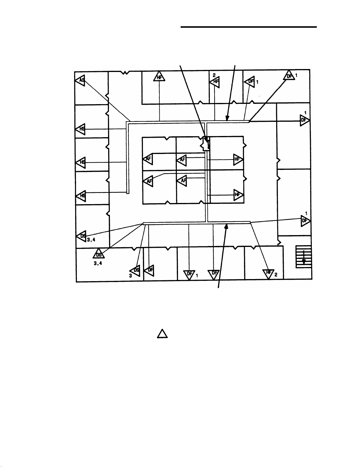
Blueprints (floor plans) are important when planning, designing, and
installing station wiring. The floor plans (Figure 1-5) provide a complete
view of all conduit and other cabling facilities in the building. These
facilities should be considered when planning site or satellite locations
and cabling.
Voice Terminals
The number of information outlets to be installed per voice terminal
location is determined by customer requirements. It may be
advantageous to install any additional information outlets required for
future growth or voice terminal rearrangements during the initial
installation.
To begin designing the station wiring, show the following information on
the floor plan(s):
●
Location of each information outlet and associated voice terminal
type if known (analog, hybrid, or digital)
●
Any associated voice terminal adjuncts or modules and the
required powering arrangements.
1-11
Page 21
CHAPTER 1. INTRODUCTION
SITE OR SATELLITE
LOCATION
CABLE DUCT*
CABLE DUCT*
* AN OPTION TO THE CABLE DUCT SHOWN IS TO RUN CABLES
(PLENUM-APPROVED, IF APPROPRIATE OR REQUIRED)
ABOVE A DROP/FALSE CEILING.
- INFORMATION OUTLET LOCATION
SPEAKERPHONE
ANALOG VOICE TERMINAL
A -
HYBRID VOICE TERMINAL
H -
DIGITAL VOICE TERMINAL
D S -
SURFACE MOUNTED INFORMATION OUTLET
F -
FLUSH MOUNTED INFORMATION OUTLET
1 2 -
AMPLIFIED HEADSET
3 -
CALL COVERAGE MODULE
4 -
FUNCTION KEY MODULE
5 -
DISPLAY MODULE
Figure 1-5. Sample Floor Plan With Voice Terminal Locations
Marked
1-12
Page 22

Planning
Site or Satellite Closets
When determining the location of site or satellite closets, use the
following information as a guide. Show the locations on the floor plan.
Keep the number of locations to a minimum.
a.
Centrally locate the site or satellite closets among the information
b.
outlets to minimize station wiring distances.
Site or satellite closets must be easily accessible and contain
c.
enough ac power receptacles to serve the equipment that will be
located there. Voice terminals equipped with adjuncts that require
power can be remotely powered from:
●
a site or satellite location
●
from the main equipment room
●
information outlets.
The distance between the power supply and the voice terminal
d.
cannot exceed 250 feet of 24-gauge wire.
Locks should be provided for the site or satellite closet doors to
e.
prevent tampering with the equipment.
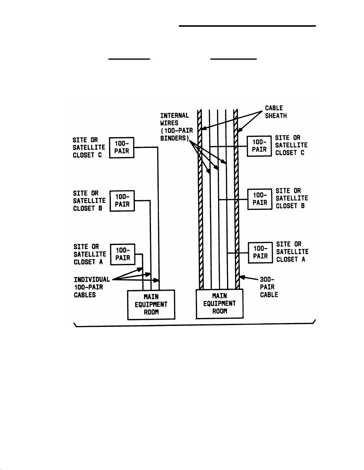
Cabling Facilities
The method of riser cable distribution between the main equipment
room and site or satellite closets is usually determined by the type of
cabling facilities (riser closets, conduit size, cabling shafts, etc.) in the
building (Figure 1-6).
The preferred arrangement is to have individual cables supply each
a.
site or satellite closet.
A second method is to have one or two large cables supply all the
b.
site or satellite closets. This requires that smaller cables be installed
between the main riser cable and the site or satellite closet. These
smaller cables are then spliced into the main cable.
Determine the type of cabling required and mark the type and routing on
the floor plan. Also, show any additional cabling facilities required for
riser and terminal cabling.
1-13
Page 23
CHAPTER 1. INTRODUCTION
PREFERRED
INDIVIDUAL 100-PAIR
RISER CABLES
ACCEPTABLE
MAIN RISER CABLE WITH
SMALLER CABLES SPLICED TO IT
CAUTION:
1-14
TWO POSSIBLE WAYS TO PLACE RISER CABLE
THE UNIFORM WIRING PLAN SHOULD NOT CONTAIN ANY BRIDGE
TAPS (AN UNUSED CABLE PAIR CONNECTED TO A WORKING CABLE
OR THE CONTINUATION OF A WORKING PAIR PAST THE POINT
AT WHICH A TERMINAL HAS BEEN CONNECTED).
Figure 1-6. Riser Cable Placement
Page 24

CHAPTER 2. HARDWARE
(66/110-Type)
General
110-Type Hardware Description
110-Type Wiring Blocks
Index Strips and Connecting Blocks
110A-Type Hardware
110P-Type Hardware
188-Type Backboards
Cords
110-Type Patch Cords
F-61789 Power Adapter Cords
Test Cords
Jumpers
Tools
F Clip Terminal Insulator
Designation Strips
66-Type Hardware Description
66M1-50 Connecting Block
Connectorized 66-Type Connecting Blocks
Multiple-Mounted 66-Type Connecting Blocks
183-Type Backboards
187B1 Backboard
Power Adapter Cords
Jumpers
Tools
Bridging Clips
2-1
2-3
2-3
2-4
2-7
2-11
2-18
2-18
2-18
2-20
2-21
2-21
2-21
2-22
2-22
2-23
2-23
2-24
2-25
2-26
2-28
2-28
2-29
2-30
2-30
Associated Hardware
Cable Slack Managers
General
Z113A Housing
Z114A Housing
Network Interfaces
RJ21X Network Interface
RJ2GX Network Interface
1.544 Mbps Digital Service Interface
Sneak Fuse Panels
2-31
2-31
2-31
2-33
2-33
2-34
2-34
2-34
2-34
2-34
-i-
Page 25

575-4 Sneak Current Fuse Panel
Emergency Transfer Units
General
Z1A Emergency Transfer Unit
574-5 Power Transfer Unit
Trunk Concentrator Cables
WP-90929, List 1, Cable Assembly (For 110-type Hardware
Only)
WP-90929, List 2, Cable Assembly (For 66-type Hardware
Only)
WP-90929, List 3, Cable Assembly (For 110-type Hardware
Only)
WP-90929, List 4, Cable Assembly (For 66-type Hardware
Only)
16-Port Analog Line Circuit Pack Adapter Cable (For 110-Type
Hardware Only)
4-Port Met Line Circuit Pack Concentrator Cable
2-34
2-37
2-37
2-37
2-37
2-39
2-39
2-42
2-43
2-45
2-45
2-46
Adjunct Power Units
General
Individual Power Supplies
Bulk Power Supply
2-47
2-47
2-47
2-49
-ii-
Page 26

Figures
Figure 2-1.
Figure 2-2.
Figure 2-3.
Figure 2-4.
Figure 2-5.
Figure 2-6.
Figure 2-7.
Figure 2-8.
Figure 2-9.
Figure 2-10.
Figure 2-11.
Figure 2-12.
Figure 2-13.
Figure 2-14.
Figure 2-15.
Figure 2-16.
Figure 2-17.
Figure 2-18.
Figure 2-19.
Figure 2-20.
Figure 2-21.
Figure 2-22.
Figure 2-23.
Figure 2-24.
Figure 2-25.
Figure 2-26.
Block Diagram of System 75 or 75 XE Installation
110-Type Wiring Block
110-Type Index Strip With Connecting Blocks
110A-Type 100-Pair Terminal Block
110A-Type 300-Pair Terminal Block
110P-Type Terminal Block—300-Pair
Connectorized
110P-Type Terminal Block—900-Pair
Connectorized (Top)
110P-Type Terminal Block—900-Pair
Connectorized (Bottom)
3-Pair Patch Cord Used With 110-Type Hardware
F-61789 Power Adapter Cord
Designation Strip
66M1-50 Connecting Block
157B Connecting Block
183A-Type Backboard
187B1 Backboard
Power Adapter Cord
Cable Slack Managers
Model 575-4 Sneak Fuse Panel
Model 574-5 Power Transfer Unit
Trunk Concentrator Cables (WP-90929, L1 & L3)
(For 110-type Hardware Only)
Trunk Concentrator Cables (WP-90929, L2 & L4)
(For 66-type Hardware Only)
16-Port Analog Line Circuit Pack Adapter Cable
(853B Adapter)
Individual Power Supplies
AC Power Strip
346 Modular Bulk Power Supply
346A1 Power Panel Circuit Breaker Locations
2-2
2-3
2-4
2-8
2-9
2-12
2-13
2-14
2-19
2-20
2-23
2-24
2-25
2-27
2-28
2-29
2-32
2-36
2-38
2-40
2-43
2-46
2-47
2-49
2-50
2-51
-iii-
Page 27

Tables
Table 2-A. 25-Pair Cable Termination on a 110-Type Wiring
Block/66-Type Connecting Block
Table 2-B.
Table 2-C. WP-90929, List 3 and List 4, Cable Assembly
Table 2-D.
Table 2-E.
WP-90929, List 1 and List 2, Cable Assembly
Wiring
Wiring
Individual Power Supply Adjunct and Distance
Limitations
346A Power Unit Adjunct and Distance Limitations
2-5
2-41
2-44
2-48
2-52
-iv-
Page 28

CHAPTER 2. HARDWARE (66/110-Type)
CHAPTER 2. HARDWARE (66/110-Type)
General
Figure 2-1 shows the equipment required to install a System 75 or 75 XE
switch. This chapter describes the hardware (66- and 110-Type) used in
the installation process. Ordering information is provided for the required
hardware.
The sites shown in Figure 2-1 are physical locations (closets) for
pass-through connections where adjunct power can be applied. The
satellite location is a place (closet) where cross-connect administration
can be carried out, and adjunct power can be applied.
2-1
Page 29
CHAPTER 2. HARDWARE (66/110-Type)
Figure 2-1. Block Diagram of System 75 or 75 XE Installation
2-2
Page 30
110-Type Hardware Description
110-Type Hardware Description
The 110-type hardware consists of connectorized or field-terminated
terminal blocks in 100-, 300-, and 900-pair sizes. The 110-type terminal
blocks consist of the following parts:
●
110-type wiring blocks
Index strips
●
●
3-, 4-, and 5-pair connecting blocks.
110-Type Wiring Blocks
The 110-type wiring block (Figure 2-2) is a plastic wiring block equipped
with permanently attached index strips.
WIRING BLOCK
TERM
NO. 1
DESIGNATION
INDEX
STRIP
Figure 2-2. 110-Type Wiring Block
INSERT
TERM
NO. 50
2-3
Page 31

CHAPTER 2. HARDWARE (66/110-Type)
Index Strips and Connecting Blocks
The index strips (Figure 2-3) are slotted rows that provide space to
terminate 25-pair cables. The wires are placed in the slots in the index
strip. The standard termination for a 25-pair cable is shown in Table 2-A.
CABLE IS TERMINATED
IN 25-PAIR
INDEX STRIP
110-TYPE WIRING
BLOCK (TOP VIEW)
4-PAIR
CONNECTING
BLOCK
3-PAIR
CONNECTING
BLOCKS
TERMINATION
POINTS FOR
CROSS-CONNECTIONS
(JUMPERS OR
PATCH CORDS)
Figure 2-3. 110-Type Index Strip With Connecting Blocks
The connecting blocks (Figure 2-3) are equipped with clips that slice the
insulation of the wires when the connecting block is pushed onto the
index strip. The top of the connecting blocks are used for
cross-connections. When a wire is punched onto the top of the
connecting block, it makes a connection, through the connecting block,
to the wire in the index strip.
The connecting blocks come in 3-, 4-, and 5-pair blocks. When 3- or
4-pair connecting blocks are used, the last connecting block on each
index strip must be one pair larger to complete the 25-pairs. The
ordering codes determine the type of connecting blocks received with a
terminal block. The 110-type wiring blocks allow for individual 3- and
4-pair connecting blocks to be disconnected for testing without
disturbing adjacent circuits.
2-4
Page 32

110-Type Hardware Description
Table 2-A. 25-Pair Cable Termination on a 110-Type Wiring
Block/66-Type Connecting Block
Connector
Pin
Numbers
26
1
27
2
28
3
29
4
30
5
31
6
32
7
33
8
34
9
35
10
25-Pair Cable
Pair
1
2
3
4
5
6
7
8
9
10
Color
W-BL
BL-W
W-O
O-W
W-G
G-W
W-BR
BR-W
W-S
S-W
R-BL
BL-R
R-O
O-R
R-G
G-R
R-BR
BR-R
R-S
S-R
110-Type
66-Type
Wiring/Conn
Block
Terminals
1
2
3
4
5
6
7
8
9
10
11
12
13
14
15
16
17
18
19
20
2-5
Page 33

CHAPTER 2. HARDWARE (66/110-Type)
Table 2-A. 25-Pair Cable Termination on a 110-Type Wiring
Block/66-Type Connecting Block (Contd)
Connector
Pin
Numbers
36
11
37
12
38
13
39
14
40
15
41
16
42
17
43
18
44
19
45
20
25-Pair Cable
Pair
11
12
13
14
15
16
17
18
19
20
Color
BK-BL
BL-BK
BK-O
O-BK
BK-G
G-BK
BK-BR
BR-BK
BK-S
S-BK
Y-BL
BL-Y
Y-O
O-Y
Y-G
G-Y
Y-BR
BR-Y
Y-S
S-Y
110-Type
66-Type
Wiring/Conn
Block
Terminals
21
22
23
24
25
26
27
28
29
30
31
32
33
34
35
36
37
38
39
40
2-6
Page 34

110-Type Hardware Description
Table 2-A. 25-Pair Cable Termination on a 110-Type Wiring
Block/66-Type Connecting Block (Contd)
Connector
Pin
Numbers
46
21
47
22
48
23
49
24
50
25
25-Pair Cable
Pair
21
22
23
24
25
Color
V-BL
BL-V
V-O
O-V
V-G
G-V
V-BR
BR-V
V-S
S-V
110-Type
66-Type
Wiring/Conn
Block
Terminals
41
42
43
44
45
46
47
48
49
50
The 110-type hardware consists of 110A- and 110P-type hardware. The
110P-type hardware uses patch cords to make cross-connections. This
allows the customer to make cross-connections. The 110A-type
hardware uses individual jumper wires for cross-connections. For this
reason, the 110A-type hardware is not intended for customer usage
because it requires technically skilled personnel to make
cross-connections. The 110A- and 110P-type hardware should not be
mixed together in the same room.
110A-Type Hardware
The 110A-type hardware consists of a 100- or 300-pair wiring block and
the associated connecting blocks. The 100-pair wiring blocks (Figure
2-4) are arranged for field termination. The 300-pair wiring blocks
(Figure 2-5) come in both field-terminated and connectorized (with
6-foot cable stubs) types.
2-7
Page 35

CHAPTER 2. HARDWARE (66/110-Type)
Figure 2-4. 110A-Type 100-Pair Terminal Block
2-8
Page 36

110-Type Hardware Description
Figure 2-5. 110A-Type 300-Pair Terminal Block
2-9
Page 37

CHAPTER 2. HARDWARE (66/110-Type)
The 110A-type hardware can be used for the trunk/auxiliary field and all
distribution fields (port, auxiliary, and station). The following 110A-type
hardware is available.
110AE1-75FT terminal block—A kit of parts for field termination
●
of cables on a 100-pair wiring block (110AW1-100). It provides
space to terminate 8 three-pair and 12 four-pair circuits.
110AB1-100FT terminal block—A kit of parts for field termination
●
of cables on a 100-pair wiring block (110AW1-100). It provides
space to terminate 24 four-pair circuits.
●
110AC1-100FT terminal block—A kit of parts for field termination
of cables on a 100-pair wiring block (110AW1-100). It provides
space to terminate 32 three-pair circuits.
●
110AB1-300FT terminal block—A kit of parts for field termination
of cables on a 300-pair wiring block (110AW1-300). It provides
space to terminate 72 four-pair circuits.
●
110AC1-300FT terminal block—A kit of parts for field termination
of cables on a 300-pair wiring block (110AW1-300). It provides
space to terminate 96 three-pair circuits.
110AC1-300STF/6 terminal block—A factory-assembled 300-pair
●
connectorized terminal block that provides space to terminate 96
three-pair circuits. Twelve, 25-pair (6-foot long), cables equipped
with female connectors exit from the top of the block. The 25-pair
cables are factory-terminated on the wiring block in continuous
numerical order.
●
110AC1-300STM/6 terminal block—A factory-assembled 300-pair
connectorized terminal block that provides space to terminate 96
three-pair circuits. Twelve, 25-pair (6-foot long), cables equipped
with male connectors exit from the top of the block. The 25-pair
cables are factory-terminated on the wiring block in continuous
numerical order.
The 110AW1-100 or 110AW1-300 wiring blocks can be ordered
separately. Also, the 3- or 4-pair connecting blocks (110C-3 or 110C-4,
respectively) must be ordered separately.
2-10
Page 38

110-Type Hardware Description
110A-TYPE HARDWARE ORDERING INFORMATION
Description
110AE1-75FT Terminal Block
110AB1-100FT Terminal Block
110AC1-100FT Terminal Block
110AB1-300FT Terminal Block
110AC1-300FT Terminal Block
110AC1-300STF/6 Terminal Block
110AC1-300STM/6 Terminal Block
110AW1-100 Wiring Block
110AW1-300 Wiring Block
110C-3 3-Pair Connecting Block
110C-4 4-Pair Connecting Block
Comcode
104 049 093
103 823 845
103 826 780
104 049 051
104 049 069
104 049 077
104 049 085
103 804 894
103 804 902
103 801 239
103 801 247
110P-Type Hardware
The 110P-type hardware consists of 100-pair wiring blocks, separated
by horizontal patch cord troughs, mounted on a panel. The P-type
comes in both 300- and 900- pair configurations which can either be
connectorized or field terminated. The 110P-type terminal blocks are
made up of alternate rows of 110-type wiring blocks and horizontal
jumper troughs arranged in a vertical column with the troughs located
above the wiring blocks. At the bottom of the terminal block is a partially
closed duct. The field-terminated hardware must be assembled (troughs
and wiring blocks must be fastened to the back panel); the connectorized
terminals come fully assembled and ready for mounting. A 300-pair
connectorized terminal block is shown in Figure 2-6.
There are two types of 900-pair connectorized terminal blocks: one has
a connector field at the top; the other is connectorized with a 40-inch
length of cable terminated with a female 25-pair cable at the bottom
(Figures 2-7 and 2-8).
2-11
Page 39

CHAPTER 2. HARDWARE (66/110-Type)
25-PAIR
INDEX STRIPS
25-PAIR
CONNECTOR
NUMBER 12
110-TYPE 100-PAIR
WIRING BLOCK
HORIZONTAL WIRE TROUGH
25-PAIR
CONNECTOR
NUMBER 1
LABELS
INDEX STRIPS 1-4
INDEX STRIPS 5-8
INDEX STRIPS 9-12
Figure 2-6. 110P-Type Terminal Block—300-Pair Connectorized
2-12
Page 40

110-Type Hardware Description
25-PAIR
CONNECTOR
NUMBER 12
25-PAIR
CONNECTOR
NUMBER 1
25-PAIR
INDEX STRIPS
110-TYPE 100-PAIR
WIRING BLOCK
HORIZONTAL WIRE TROUGH
LABELS
25-PAIR
CONNECTOR
NUMBER 36
25-PAIR
CONNECTOR
NUMBER 25
INDEX
STRIPS
1-4
INDEX
STRIPS
5-8
INDEX
STRIPS
9-12
INDEX
STRIPS
13-16
INDEX
STRIPS
17-20
INDEX
STRIPS
21-24
INDEX
STRIPS
25-28
INDEX
STRIPS
29-32
INDEX
STRIPS
33-36
Figure 2-7. 110P-Type Terminal Block—900-Pair Connectorized
(Top)
2-13
Page 41

CHAPTER 2. HARDWARE (66/110-Type)
25-PAIR
INDEX STRIPS
LABELS
110-TYPE 100-PAIR
WIRING BLOCK
HORIZONTAL WIRE TROUGH
INDEX
STRIPS
1-4
INDEX
STRIPS
5-8
INDEX
STRIPS
9-12
INDEX
STRIPS
13-16
INDEX
STRIPS
17-20
36 CONNECTORS
INDEX
STRIPS
21-24
INDEX
STRIPS
25-28
INDEX
STRIPS
29-32
INDEX
STRIPS
33-36
Figure 2-8. 110P-Type Terminal Block—900-Pair Connectorized
(Bottom)
2-14
Page 42

110-Type Hardware Description
The 110P-type hardware can be used for the trunk/auxiliary field and all
distribution fields (port, auxiliary, and station). The following 110P-type
hardware is available.
●
110PB1-300CT terminal block—A factory-assembled 300-pair
connectorized terminal block that provides space to terminate 72
four-pair circuits. Twelve, 25-pair, female, miniature ribbon
connectors are mounted at the top of the terminal block. The
connectors are factory-terminated on the wiring block in
continuous numerical order.
●
110PC1-300CT terminal block—A factory-assembled 300-pair
connectorized terminal block that provides space to terminate 96
three-pair circuits. Twelve, 25-pair, female, miniature ribbon
connectors are mounted at the top of the terminal block. The
connectors are factory-terminated on the wiring block in
continuous numerical order.
●
110PB1-300FT terminal block—A kit of parts for field termination
of cables on a 300-pair wiring block. It provides space to terminate
72 four-pair circuits.
●
110PC1-300FT terminal block—A kit of parts for field termination
of cables on a 300-pair wiring block. It provides space to terminate
96 three-pair circuits.
●
110PE1-300CT terminal block—A factory-assembled, 300-pair,
connectorized, terminal block that provides space to terminate 32
three-pair and 48 four-pair circuits. Twelve, 25-pair, female,
miniature ribbon connectors are mounted at the top of the
terminal block. The connectors are terminated on the wiring
blocks in continuous numerical order.
●
110PE1-300CT/FT terminal block—A partially factory-assembled
300-pair terminal block that provides space to terminate 32
three-pair and 48 four-pair circuits. Four, 25-pair, female,
miniature, ribbon connectors are mounted at the top of the
terminal block. The connectors are terminated on the 3-pair wiring
block in continuous numerical order. The 4-pair wiring blocks are
available as a kit of parts to allow field termination of the 4-pair
circuits.
2-15
Page 43

CHAPTER 2. HARDWARE (66/110-Type)
●
110PE1-300FT terminal block—A kit of parts for field termination
of cables on a 300-pair terminal block. It provides space to
terminate 32 three-pair and 48 four-pair circuits.
●
110PB1-900CB terminal block—A factory-assembled, 900-pair,
connectorized, terminal block that provides space to terminate
216 4-pair circuits. Thirty-six, 25-pair cables (40-inches long),
equipped with female miniature ribbon connectors, are mounted
at the bottom of the terminal block. The cables are
factory-terminated on the wiring blocks in continuous numerical
order.
●
110PC1-900CB terminal block—A factory-assembled 900-pair
connectorized terminal block that provides space to terminate
288 three-pair circuits. Thirty-six, 25-pair cables (40-inches long),
equipped with female miniature ribbon connectors, are mounted
at the bottom of the terminal block. The cables are
factory-terminated on the wiring blocks in continuous numerical
order.
●
110PB1-900CT terminal block—A factory-assembled 900-pair
connectorized terminal block that provides space to terminate
216 four-pair circuits. Thirty-six, 25-pair, female, miniature ribbon
connectors are mounted at the top of the terminal block. The
connectors are factory-terminated on the wiring blocks in
continuous numerical order.
●
The 110PC1-900CT terminal block—a factory-assembled 900-pair
connectorized terminal block that provides space to terminate
288 three-pair circuits. Thirty-six, 25-pair, female, miniature ribbon
connectors are mounted at the top of the terminal block. The
connectors are factory-terminated on the wiring blocks in
continuous numerical order.
●
110PB1-900FT terminal block—A kit of parts for field termination
of cables on a 900-pair terminal block. It provides space to
terminate 216 four-pair circuits.
●
110PC1-900FT terminal block—A kit of parts for field termination
of cables on a 900-pair terminal block. It provides space to
terminate 288 three-pair circuits.
2-16
Page 44

110-Type Hardware Description
●
110PE1-900CT/FT terminal block—A partially factory-assembled
900-pair terminal block that provides termination space for 96
three-pair and 144 four-pair circuits. Twelve, 25-pair, female,
miniature, ribbon connectors are mounted at the top of the
terminal block. The connectors are terminated on the 3-pair wiring
blocks in a continuous numerical order. The 4-pair wiring blocks
are available as a kit of parts to allow field termination of the 4-pair
circuits.
●
110PE1-900FT terminal block—A kit of parts for field termination
of cables on a 900-pair terminal block. It provides space to
terminate 96 three-pair and 144 four-pair circuits.
110P-TYPE HARDWARE ORDERING INFORMATION
Description
110PB1-300CT Terminal Block
110PC1-300CT Terminal Block
110PB1-300FT Terminal Block
110PC1-300FT Terminal Block
110PE1-300CT Terminal Block
110PE1-300CT/FT Terminal Block
110PE1-300FT Terminal Block
110PB1-900CB Terminal Block
110PC1-900CB Terminal Block
110PB1-900CT Terminal Block
110PC1-900CT Terminal Block
Comcode
103 823 886
103 804 852
103 804 829
103 804 860
104 017 066
104 173 166
103 823 902
104 173 158
104 166 590
103 804 837
103 048 878
110PB1-900FT Terminal Block
110PC1-900FT Terminal Block
110PE1-900CT/FT Terminal Block
110PE1-900FT Terminal Block
103 804 845
103 804 886
104 173 174
103 823 910
2-17
Page 45

CHAPTER 2. HARDWARE (66/110-Type)
188-Type Backboards
The 188-type backboards are wire troughs that channel the patch cords
or cross-connecting wire between the wiring blocks. The backboards
consist of a metal frame equipped with retaining rings. They are
available in four types:
The 188B1 backboard is a horizontal wire trough that is used with
●
110A-type terminal blocks.
●
The 188C2 backboard is a vertical wire trough that is used with
900-pair 110P-type terminal blocks.
●
The 188D2 backboard is a vertical wire trough that is used with
300-pair 110P-type terminal blocks.
●
The 188E2 backboard is a horizontal wire trough that is used
between the trunk/auxiliary field and the distribution field for
either 300- or 900-pair 110P-type terminal blocks.
188-TYPE BACKBOARD ORDERING INFORMATION
Description Comcode
188B1 Backboard
188C2 Backboard
188D2 Backboard
188E2 Backboard
102 689 569
104 031 794
104 032 404
104 031 802
Cords
110-Type Patch Cords
The 1-pair and 3-pair patch cords (Figure 2-9) are used to cross-connect
terminals to switch ports at the cross-connect field. The patch cords are
available in several lengths. The patch cords are equipped with a plastic
plug on each end. The plastic plugs are compatible with the 110-type
connecting blocks used on the wiring blocks. The patch cords are keyed
so that they cannot be inserted upside down or on a split pair.
2-18
Page 46

110-Type Hardware Description
PLUGS
Figure 2-9. 3-Pair Patch Cord Used With 110-Type Hardware
110-TYPE PATCH CORD ORDERING INFORMATION
Cord
Description Length
(1 per package) (10 per package)
F-61679-2
F-61679-3
F-61679-4
F-61679-5
F-61679-6
F-61679-7
F-61679-8
F-61679-9
F-61679-19
110P6A2B
110P6A3B
110P6A4B
110P6A5B
110P6A6B
110P6A7B
110P6A8B
110P6A9B
110P6A19B
1-Pair
1-Pair
1-Pair
1-Pair
1-Pair
1-Pair
1-Pair
1-Pair
1-Pair
3-Pair
3-Pair
3-Pair
3-Pair
3-Pair
3-Pair
2 ft
3 ft
4 ft
5 ft
6 ft
7 ft
8 ft
9 ft
19 ft
2 ft
3 ft
4 ft
5 ft
6 ft Not Available
7 ft
3-Pair 8 ft Not Available
3-Pair 9 ft
3-Pair 19 ft
Comcode
103 991 873
103 991 881
103 991 899
103 991 907
103 991 915
103 991 923
103 991 931
103 991 949
103 991 956
Not Available
Not Available
Not Available
Not Available
Not Available
Not Available
Not Available
Comcode
Not Available
Not Available
Not Available
104 073 606
Not Available
Not Available
Not Available
104 073 614
104 073 622
103 882 965
103 882 957
103 882 940
103 882 973
103 882 932
103 882 924
103 882 916
103 882 908
103 882 890
2-19
Page 47

CHAPTER 2. HARDWARE (66/110-Type)
F-61789 Power Adapter Cords
The F-61789 power adapter cord (Figure 2-10) is used at the equipment
room or satellite closet cross-connect field to connect an adjunct power
supply to a 4-pair connecting block that is mounted on a 110-type wiring
block. The power adapter cord is a 1-pair cable equipped with a
6-conductor modular plug on one end, and a 1-pair, 110-type patch cord
plug on the other end. The modular plug connects to an adjunct power
supply, and the patch cord plug connects to a connecting block
mounted on a 110-type wiring block.
1-PAIR
PLUG
Figure 2-10. F-61789 Power Adapter Cord
POWER ADAPTER CORD ORDERING INFORMATION
Cord
Length
F-61789-5 5 ft
F-61789-9 9 ft
F-61789-19
19 ft
MODULAR
PLUG
Comcode
Comcode
(1 per package) (10 per package)
103 907 184
103 907 192
103 907 200
103 891 800
103 891 792
103 891 784
2-20
Page 48

110-Type Hardware Description
Test Cords
The D test cord provides test access to one pair of wires without
removing any jumpers.
D TEST CORD ORDERING INFORMATION
Cord
Length
D Test Cord 4 ft
D Test Cord 8 ft
Comcode
402 023 949
402 023 956
Jumpers
Solid wire jumpers can be used to make cross-connections instead of
the 1- and 3-pair patch cords. The jumpers are terminated on the
connecting blocks with an impact tool.
JUMPER WIRE ORDERING INFORMATION
Jumper Wire
Description
Comcode
(Order by Footage)
DT 24M-Y/BL/R/G
DT 24P-W/BRN
DT 24P-Y/BL
DT 24P-Y/G
DT 24P-Y/O
DT 24P-Y/R
2-Pair
1-Pair
1-Pair
1-Pair
1-Pair
1-Pair
103 252 557
102 484 045
102 379 195
103 252 565
103 252 573
103 252 581
Tools
The following tools are required terminate the wires/jumpers on
field-terminated wiring blocks:
The D impact tool (AT-8762) is a single-wire termination tool
●
The 788J1 impact tool will terminate five pairs of wire at a time
●
The 788K1 conductor retention tool is used to secure cable pairs
●
in the wiring blocks when connecting blocks are being removed
from the wiring blocks.
2-21
Page 49

CHAPTER 2. HARDWARE (66/110-Type)
110-TYPE TOOLS ORDERING INFORMATION
Description Comcode
D Impact Tool
788J1 Impact Tool
402 024 723
102 648 839
788K1 Conductor Retention Tool 102 655 495
F Clip Terminal Insulator
The F clip terminal insulator (AT-8660F) is used to identify special
circuits. Each insulator identifies one pair and may be located in
adjacent pair positions without interference.
F CLIP TERMINAL INSULATOR ORDERING INFORMATION
Description
F Clip Terminal Insulator
Comcode
401 149 802
Designation Strips
Designation strips (Figure 2-11) are made of clear plastic and snap into
alternate rows of the 110-type wiring block. Each designation strip can
identify 50-pairs of wire. The designation strips accept the standard
110-labels that are ordered separately. The designation strips are
furnished with the 110-type terminal blocks, but they can also be
ordered separately.
DESIGNATION STRIP ORDERING INFORMATION
Description
188&T1-50 Designation Strip
Qty. Per Code
6
Comcode
103 895 504
2-22
Page 50

CLEAR PLASTIC
DESIGNATION
STRIP
66-Type Hardware Description
Figure 2-11. Designation Strip
66-Type Hardware Description
The 66-type hardware consists of non-connectorized or connectorized
connecting blocks. The connecting blocks can be mounted individually
or in multiple arrangements. All 66-type hardware uses the same basic
connecting block, a 66M1-50.
66M1-50 Connecting Block
The 66M1-50 (Figure 2-12) connecting block is a plastic connecting
block containing quick connect terminals sized to terminate 20 to 24
gauge wire. It has 50 rows of terminals with four terminals in each row.
The first two and last two terminals of each row are connected together
and each row is split between the second and third terminals (Figure
2-12). These terminals provide space to terminate one 25-pair cable and
the associated jumpers. The terminals slice the insulation of the wires
when the wires are punched onto the terminals. The standard
termination for a 25-pair cable on a 66M1-50 connecting block is shown
in Table 2-A. The 66M1-50 connecting block can be mounted directly on
2-23
Page 51

CHAPTER 2. HARDWARE (66/110-Type)
the wall or on a backboard. These connecting blocks are used in the
equipment room for the distribution field.
Figure 2-12. 66M1-50 Connecting Block
Connectorized 66-Type Connecting Blocks
The connectorized version of the 66-type connecting block is the 157B
(Figure 2-13) connecting block. It consists of a 66M1-50 connecting
block prewired to a 50-pin connector mounted on each side of the
2-24
Page 52

66-Type Hardware Description
connecting block. Each 157B connecting block can terminate two
25-pair cables. It can be mounted directly on the wall or on a backboard.
These connecting blocks are used in the equipment room for the
trunk/auxiliary and distribution fields.
Figure 2-13. 157B Connecting Block
Multiple-Mounted 66-Type Connecting Blocks
Connectorized 66-type connecting blocks are available in two multiple
mounting arrangements. The 166-type backboard consists of eight
157B connecting blocks factory-mounted on a purple backboard. This
multiple arrangement provides space to terminate sixteen 25-pair
cables. The 166-type backboard is used in the equipment room for the
trunk/auxiliary field and distribution field.
2-25
Page 53

CHAPTER 2. HARDWARE (66/110-Type)
The 154A-type backboard consists of four 157B connecting blocks
factory-mounted on a blue backboard. This multiple arrangement
provides space to terminate eight 25-pair cables. The 154A-type
mounting is used in the equipment room in the distribution field.
66-TYPE CONNECTING BLOCKS ORDERING INFORMATION
Description Comcode
66M1-50 Connecting Block
157B Connecting Block
166-Type Backboard
154A-Type Backboard
101 238 178
403 613 003
403 612 922
403 612 997
183-Type Backboards
The 183-type backboard (Figure 2-14) provides mounting space for
66M1-50 connecting blocks. It is available in the four colors (blue,
green, purple, and yellow) that are used to identify the functional areas
in the cross-connect field. The 183A-type backboard mounts four
66M1-50 connecting blocks. The 183B-type backboard mounts eight
66M1-50 connecting blocks. The 183C-type backboard mounts two
66M1-50 connecting blocks. White backboards that are used for
connections between the main distribution field and satellite closets can
be obtained from outside vendors.
2-26
Page 54

66-Type Hardware Description
Figure 2-14. 183A-Type Backboard
183-TYPE BACKBOARD ORDERING INFORMATION
Code
Color
183A1 Blue
Mounts
(4) 66M1-50 101 412 963
Comcode
Conn Blocks
183A2 Green
(4) 66M1-50 101 412 971
Conn Blocks
183A4 Purple
(4) 66M1-50 101 937 902
Conn Blocks
183A5 Yellow
(4) 66M1-50 101 986 446
Conn Blocks
183B1 Blue
(8) 66M1-50 101 412 989
Conn Blocks
183B2 Green
(8) 66M1-50 101 564 631
Conn Blocks
183B4 Purple
(8) 66M1-50 101 937 928
Conn Blocks
183B5 Yellow
(8) 66M1-50 101 986 453
Conn Blocks
183C1 Blue
(2) 66M1-50 103 222 790
Conn Blocks
2-27
Page 55

CHAPTER 2. HARDWARE (66/110-Type)
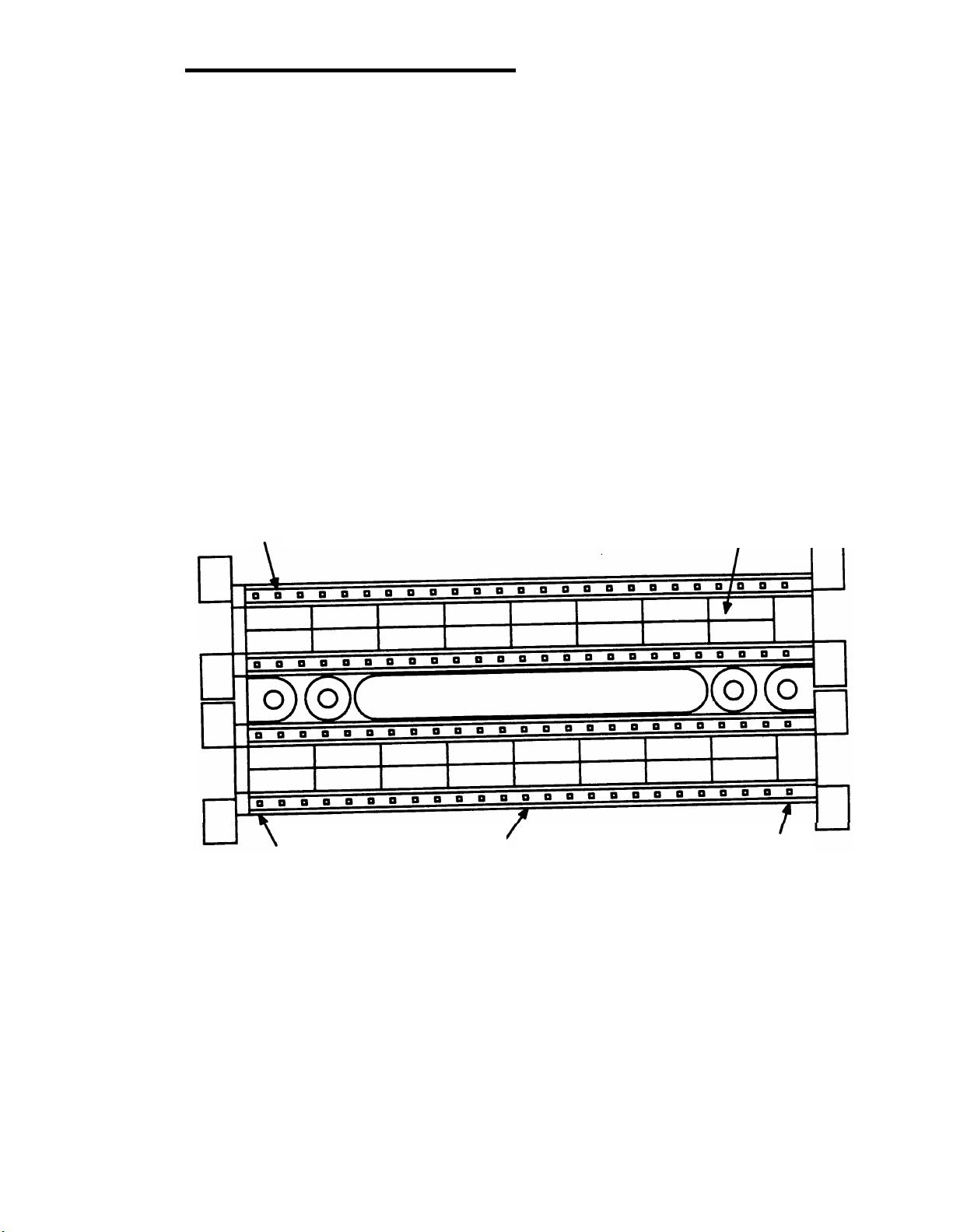
187B1 Backboard
The 187B1 backboard (Figure 2-15) provides 16 pegs that are used to
dress the cross-connecting wire between connecting blocks. The
187B1 backboards can be used with any arrangement of 66-type
connecting blocks.
Figure 2-15. 187B1 Backboard
187B1 BACKBOARD ORDERING INFORMATION
Description
187B1 Backboard
Comcode
101 937 944
Power Adapter Cords
The power adapter cord (Figure 2-16) connects an adjunct power
supply to a 4-pair station circuit terminated on a 66-type connecting
block. The cord consists of a 2-pair cable equipped with a 6-conductor
modular plug. The plug end connects to the power supply and the other
end terminates on the 66-type connecting block.
2-28
Page 56

66-Type Hardware Description
MODULAR
PLUG
Figure 2-16. Power Adapter Cord
POWER ADAPTER CORD ORDERING INFORMATION
Length
10 ft
25 ft
Comcode
103 935 623
103 895 660
Jumpers
Solid wire jumpers are used for cross-connections between terminals
on the connecting blocks. The jumpers are punched down on the
connecting blocks with a termination tool.
JUMPER WIRE ORDERING INFORMATION
Jumper Wire
DT 24M-Y/BL/R/G
DT 24P-W/BRN
DT 24P-Y/BL
DT 24P-Y/G
DT 24P-Y/O
DT 24P-Y/R
Description
2-Pair
1-Pair
1-Pair
1-Pair
1-Pair
1-Pair
Comcode
(Order by Footage)
103 252 557
102 484 045
102 379 195
103 252 565
103 252 573
103 252 581
2-29
Page 57

CHAPTER 2. HARDWARE (66/110-Type)
Tools
The following tools are used to terminate or remove the wire on the
connecting blocks:
●
The 714B tool is a nonimpact single-wire termination tool
The D impact tool (AT-8762) is a single-wire impact termination
●
tool
●
The 724A tool is used to remove wires from the connecting
blocks.
66-TYPE TOOLS ORDERING INFORMATION
Description
714B Tool
Blade AT-8762
D Impact Tool
724A Tool
Comcode
100 755 511
402 024 681
402 024 723
100 755 636
Bridging Clips
Bridging clips are spring clips that connect two adjacent terminals in the
same terminal row on a connecting block. Bridging clips provide the
fastest, most reliable way to make cross-connections. No special tools
are required to install or remove the clips.
BRIDGING CLIPS ORDERING INFORMATION
Description
BCSS-2 Bridging Clip 403 596 035
Comcode
2-30
Page 58

Associated Hardware
Associated Hardware
Cable Slack Managers
General
The cable slack managers (Figure 2-17) are raised floor units that are
used for cable distribution and cable slack storage between the switch
cabinets and the cross-connect field. They can also accommodate a
limited amount of slack in station cables. Power cables from the switch
cabinets are also run through/from the cable slack managers.
Note: Cable slack managers are not required when the switch
cabinet is installed on a raised computer floor. The station cables
and the cables from the switch cabinets are routed under the
computer flooring to the cross-connect field.
The cable slack managers have tabs and interlocks that allow adjacent
cable slack managers to interlock together. Retainers mounted on
columns inside the cable slack managers keep the cables from
protruding above the top of the base. The cable slack managers are
coded as housings and two types are available.
2-31
Page 59

CHAPTER 2. HARDWARE (66/110-Type)
Z814A
COVER
Z814A
COVER
Z815A
COVER
Z8A1 BASE
Z6A RETAINER
Z113A HOUSING
Z814A
COVER
Z8A1 BASE
2-32
Z114A HOUSING
Figure 2-17. Cable Slack Managers
Page 60

Associated Hardware
Z113A Housing
The Z113A housing is used between the wall and equipment cabinets
(switch, AP, auxiliary, etc.). It consists of:
●
(1) Z8A1 base
●
(2) Z814A covers
(25) Z6A retainers.
●
Z114A Housing
The Z114A housing is designed to be used adjacent to the Z113A
housing if no equipment cabinet exists at the position or if the cabinet(s)
is positioned against the wall with the cross-connect field beside the
cabinet(s). It consists of:
●
(1) Z8A1 base
●
(1) Z814A cover
(1) Z815A cover
●
(25) Z6A retainers.
●
CABLE SLACK MANAGER ORDERING INFORMATION
Z113A Housing
Z114A Housing
Z8A1 Base
Z814A Cover
Z815A Cover
Z6A Retainer
Description
Comcode
103 961 322
103 961 330
103 965 133
103 965 141
103 965 158
103 965 166
2-33
Page 61

CHAPTER 2. HARDWARE (66/110-Type)
Network Interfaces
RJ21X Network Interface
The RJ21X network interface is the connection point between the local
telephone company lines (1-pair trunks) and the switch. The interface is
supplied and installed by the local telephone company. See Table 3-G
for network interface pin assignments on CO and DID trunk circuit
packs.
RJ2GX Network Interface
The RJ2GX network interface is the connection point between the local
telephone company tie-trunks and the switch three-pair tie-trunks. The
interface is supplied and installed by the local telephone company. See
Table 3-G for network interface pin assignments on tie trunk circuit
packs.
1.544 Mbps Digital Service Interface
The 1.544 Mbps (megabits per second) digital service interface is the
connection point between the local telephone company T1 carrier lines
and the switch DS1 trunks. The interface is supplied and installed by the
local telephone company.
Sneak Fuse Panels
575-4 Sneak Current Fuse Panel
Sneak current protection is required between the RJ21X or RJ2GX
network interface and the switch for both trunk and off-premises circuit
packs. See Installing Off-Premises Voice Terminal Wiring in Chapter 4.
The Model 575-4 sneak current fuse panel (Figure 2-18), or equivalent,
is recommended for sneak current protection. The panel is
connectorized with incoming and outgoing connectors and equipped
with 25 two-pair fuse modules. Connector cables (B25A) connect the
network interface to the sneak fuse panel. Also, 157B connecting
blocks equipped with SCP-1 protectors can be used for sneak current
protection.
2-34
Page 62

Associated Hardware
Note: Sneak current protectors with a rating of 350 ma at 600V
must be UL rated for domestic installation and CSA certified for
Canadian installation.
SNEAK FUSE PANEL ORDERING INFORMATION
Description
157B Connecting Block
Comcode
403 613 003
SCP-1 Protector* 403 617 632
575-4 Sneak Current Fuse Panel 402 989 016
*The SCP-1 protectors must be ordered separately and installed on the 157B
connecting block. Twenty-four protectors are required per block.
2-35
Page 63

CHAPTER 2. HARDWARE (66/110-Type)
25-PAIR
MALE
CONNECTOR
IN
FUSE
MODULE
25-PAIR
FEMALE
CONNECTOR
OUT
2-36
Figure 2-18. Model 575-4 Sneak Fuse Panel
Page 64

Associated Hardware
Emergency Transfer Units
General
The emergency transfer units used with the 66-type/110-type hardware
are the Z1A emergency transfer unit and the 574-5 power transfer unit.
The units mount on the plywood backboard to the left of the
trunk/auxiliary field.
Z1A Emergency Transfer Unit
The Z1A emergency transfer unit provides emergency transfer
connections for six telephones. If the central office (CO) trunks require
ground start, a ground start key must be installed on each emergency
transfer telephone.
574-5 Power Transfer Unit
The 574-5 power transfer unit (Figure 2-19) provides power transfer
connections for five telephones. This unit provides automatic ground
start.
2-37
Page 65

CHAPTER 2. HARDWARE (66/110-Type)
MFG. BY PORTA SYSTEMS
2-38
TRUNK LINE
MODEL 574-5
PAT PENDING
EXT
Figure 2-19. Model 574-5 Power Transfer Unit
Page 66

Associated Hardware
Trunk Concentrator Cables
Trunk concentrator cables are used for the following purposes:
To match 1-pair local telephone company trunks to 3-pair switch
●
circuits at the cross-connect field.
To match 1-pair local telephone company trunks provided for
●
off-premises lines to 3-pair switch circuits at the cross-connect
field.
●
To split eight 3-pair analog tie trunks into two groups of four
3-pair tie trunks.
The trunk concentrator cables are 25 feet long. They are coded as cable
assemblies and described in the following sections.
Note: The WP-90929, List 1 and List 3 cable assemblies are used
with 110-type hardware, while List 2 and 4 cable assemblies are
used with 66-type hardware.
WP-90929, List 1, Cable Assembly (For 110-type Hardware Only)
The WP-90929, List 1, cable assembly (Figure 2-20 and Table 2-B)
provides a way to connect local telephone company trunks to the
switch. It can also be used to connect off-premises analog trunks
between the port field and trunk field at the equipment room
cross-connect field. All the ribbon connectors on the cable assembly
are male-type connectors. Each cable assembly can match twenty-four
1-pair trunk circuits with twenty-four 3-pair trunk circuits.
2-39
Page 67

CHAPTER 2. HARDWARE (66/110-Type)
CONNECTS
TO 110
TERMINAL
BLOCK
CONNECTOR
CONNECTS
TO 110
TERMINAL
BLOCK
CONNECTOR
CONNECTS
TO SWITCH
CABINET
CONNECTOR "O"
LIST 1 CABLE
CONNECTS
TO SWITCH
CABINET
CONNECTOR "O"
LIST 3 CABLE
LEGEND:
25-PAIR MALE CONNECTOR
M =
F =
25-PAIR FEMALE CONNECTOR
Figure 2-20. Trunk Concentrator Cables (WP-90929, L1 & L3) (For
110-type Hardware Only)
2-40
Page 68

Associated Hardware
Table 2-B. WP-90929, List 1 and List 2, Cable Assembly Wiring
Conn. 0
Pin
No.
26
27
28
29
30
31
32
33
34
35
36
37
38
39
40
41
42
43
44
45
46
47
48
49
50 V-S
Cable
No. 1
Cable
No. 2
Cable
No. 3
W-BL - -
W-BR
R-O
R-S
BK-G
-
- -
- -
- -
Y-BL - -
Y-BR
V-O
-
-
-
- -
- -
W-BL
W-BR
R-O
- R-S
-
-
-
-
- -
- -
BK-G
Y-BL Y-BR
V-O
W-BL
W-BR
- -
- -
- -
- -
- -
BK-G
Y-BL
Y-BR
- -
- -
-
-
-
-
-
-
-
-
R-O
R-S
V-O
Conn. 0
Pin
Numbers
1
2
3
Cable
No. 1
BL-W
BR-W
O-R
Cable
No. 2
4 S-R - 5
6
7
8
9
10
11
12
13
14
15
16
17
18
19
20
21
22
23
24
25
G-BK
BL-Y - BR-Y
O-V
-
-
BL-W
BR-W
-
-
-
-
-
-
- -
- -
- -
- -
- -
- -
- -
- -
S-V
- -
- -
- -
-
- -
- -
O-R
S-R
G-BK
BL-Y
BR-Y
O-V
-
Cable
No. 3
-
-
-
-
-
-
-
-
-
BL-W
BR-W
O-R
S-R
G-BK
BL-Y
BR-Y
O-V
-
2-41
Page 69

CHAPTER 2. HARDWARE (66/110-Type)
WP-90929, List 2, Cable Assembly (For 66-type Hardware Only)
The WP-90929, List 2, cable assembly (Figure 2-21 and Table 2-B)
provides a way to connect local telephone company trunks to the
switch. It can also be used to connect off-premises analog trunks
between the port field and trunk field at the equipment room
cross-connect field. The 3-fingered end of the cable assembly is
equipped with male-type ribbon connectors. The other end of the cable
assembly is equipped with a female-type ribbon connector. Each cable
assembly can match twenty-four 1-pair trunk circuits with twenty-four
3-pair trunk circuits.
2-42
Page 70

Associated Hardware
CONNECTS
TO 66-TYPE
CONNECTING
BLOCK
CONNECTS
TO 66-TYPE
CONNECTING
BLOCK
CONNECTS
TO SWITCH
CABINET
CONNECTOR "O"
LIST 2 CABLE
CONNECTS
TO SWITCH
CABINET
CONNECTOR "O"
LIST 4 CABLE
LEGEND:
M = 25-PAIR MALE CONNECTOR
F = 25-PAIR FEMALE CONNECTOR
Figure 2-21. Trunk Concentrator Cables (WP-90929, L2 & L4) (For
66-type Hardware Only)
WP-90929, List 3, Cable Assembly (For 110-type Hardware Only)
The WP-90929, List 3, cable assembly (Figure 2-20 and Table 2-C)
provides a way to connect tie-trunk circuits to the switch. All ribbon
connectors on the cable assembly are male-type connectors. Each
cable assembly can match eight 3-pair tie-trunk circuits with two groups
of four 3-pair tie-trunk circuits.
2-43
Page 71

CHAPTER 2. HARDWARE (66/110-Type)
Table 2-C. WP-90929, List 3 and List 4, Cable Assembly Wiring
Conn. 0
Pin Cable Cable
No.
26
27
28
29
30
31
32
33
34
35
36
37
38
39
40
41
42
43
44
45
46
47
48
49
50
No. 1
W-BL -
W-O
W-G
W-BR
W-S
R-BL
R-O
R-G
R-BR
R-S
BK-BL -
BK-O
-
-
-
-
-
-
-
-
-
-
-
-
V-S
No. 2
-
-
-
-
-
-
-
-
-
-
W-BL
W-O
W-G
W-BR
W-S
R-BL
R-O
R-G
R-BR
R-S
BK-BL
BK-O
Conn. 0
Pin
Numbers
1
2
3
4
5
6
7
8
9
10
11
12
13
14
15
16
17
18
19
20
21
22
23
24
25
Cable
No. 1
Cable
No. 2
BL-W
O-W
G-W
BR-W
S-W
BL-R
O-R
G-R
BR-R
S-R
BL-BK -
O-BK
-
-
-
-
-
-
-
-
-
-
-
-
BL-W
O-W
G-W
BR-W
S-W
BL-R
O-R
G-R
BR-R
S-R
BL-BK
O-BK
S-V
-
-
-
-
-
-
-
-
-
-
-
-
2-44
Page 72

Associated Hardware
WP-90929, List 4, Cable Assembly (For 66-type Hardware Only)
The WP-90929, List 4, cable assembly (Figure 2-21 and Table 2-C)
provides a way to connect tie-trunk circuits to the switch. The 2-fingered
end of the cable assembly is equipped with male-type ribbon connectors.
The other end of the cable assembly is equipped with a female-type
ribbon connector. Each cable assembly can match eight 3-pair tie-trunk
circuits with two groups of four 3-pair tie-trunk circuits.
TRUNK CONCENTRATOR CABLE ORDERING INFORMATION
Description
Comcode
WP-90929, List 1, Cable Assembly 405 064 999
WP-90929, List 2, Cable Assembly 405 065 012
WP-90929, List 3, Cable Assembly 405 075 482
WP-90929, List 4, Cable Assembly 405 075 540
16-Port Analog Line Circuit Pack Adapter Cable (For 110-Type Hardware Only)
The 16-port analog line circuit pack (TN746) contains sixteen 1-pair
circuits that appear on a 25-pair connector at the switch. The 16-port
analog line adapter cable (Figure 2-21) separates the 1-pair circuits
(from the switch) into 3-pair circuits that appear on two 25-pair
connectors at the other end of the cable.
2-45
Page 73

CHAPTER 2. HARDWARE (66/110-Type)
CONNECTS
TO 16-PORT
ANALOG
LINE
CIRCUIT
PACK
LEGEND:
M = 25-PAIR MALE CONNECTOR
F = 25-PAIR FEMALE CONNECTOR
NOTE: AN A25D CABLE MUST BE USED BETWEEN
THE ADAPTER CABLE AND THE 110-TYPE
TERMINAL BLOCK.
CONNECTS
TO CROSSCONNECT
FIELD
(NOTE)
Figure 2-22. 16-Port Analog Line Circuit Pack Adapter Cable (853B
Adapter)
The adapter cable is 8 feet long and can be ordered with the TN746
circuit pack. The adapter cable is coded as a 853B adapter and can be
ordered as follows.
16-PORT ANALOG LINE
ADAPTER CABLE ORDERING INFORMATION
Description Comcode
853B Adapter
104 305 834
4-Port Met Line Circuit Pack Concentrator Cable
The MET line circuit pack (TN735) contains four 3-pair circuits that
appear on a 25-pair connector at the switch. The WP-90929, List 3 and
List 4 cable assemblies shown in Figures 2-19 and 2-20, respectively
combine the MET line circuits appearing on two 25-pair connectors (at
the switch) into one 25-pair connector at the opposite end of the cable.
2-46
Page 74

Adjunct Power Units
Adjunct Power Units
General
There are two types of power supplies used for adjunct powering,
individual and bulk. The power supplies are specified by the Field
Services Organization (FSO) for firm quote price lists. For all other
quotes, the power supplies are specified by the PSC.
Individual Power Supplies
Individual power supplies (Figure 2-23) can be used for powering from
the equipment room, site or satellite locations, or information outlets.
An individual power supply can power only one voice terminal. Table
2-D contains the individual power supply limitations for distance, wire
gauge, and adjuncts.
2012D TRANSFORMER
329A
(NOTE 1)
NOTES:
1.
2.
THE 329A AND THE KS-22911, L1
ARE SIMILAR IN APPEARANCE.
THE 2012D TRANSFORMER AND 248B
TRANSFORMER MUST BE ORDERED
SEPARATELY AND FIELD ASSEMBLED
AS SHOWN.
WITH 248B ADAPTER
(NOTE 2)
Figure 2-23. Individual Power Supplies
2-47
Page 75

CHAPTER 2. HARDWARE (66/110-Type)
Table 2-D. Individual Power Supply Adjunct and Distance
Limitations
Power Unit
2012D with
248B Adapter
(18-volt ac)
KS-22911, L1
(48-volt dc)
Adjunct Limits
One speakerphone
or headset only
One digital module plus
speakerphone or headset
One digital module plus
Wire
Gauge
24
24
24
Distance
speakerphone or headset
329A*
(–48 volt dc)
Two digital modules plus
speakerphone or headset
Three digital modules plus
24
24
speakerphone or headset
* The 329A should not be used to power attendant consoles.
INDIVIDUAL POWER SUPPLY ORDERING INFORMATION
Description Comcode
2012D Transformer
248B Adapter
KS-22911, L1 Power Unit
329A Power Unit
102 600 517
102 802 103
403 242 639
103 873 998
Feet
150
300
500
350
250
When more than one individual power supply is at the equipment room
or at a site or satellite location, an ac power strip (Figure 2-24) must be
installed to accommodate the various sizes of power supplies.
Note:
A 543A power unit (Comcode 104 034 541) may be required
for inrush protection for a 20 amp 120-volt ac line serving multiple
329A power units. Contact your PSC for details. Most multiple
powering requirements should be served by the 346 modular bulk
power supply.
2-48
Page 76

AC POWER STRIP (NOTE)
NOTE: THIS AC POWER STRIP MUST BE
LOCALLY PROVIDED.
Adjunct Power Units
OUTLET
SPACING
3.5 TO 4 INCHES
Figure 2-24. AC Power Strip
Bulk Power Supply
The 346 modular bulk power supply consists of a 346A1 power panel
and up to three 346A power units (Figure 2-25). The panel has three
2-ampere circuit breakers, one for each 346A power unit (Figure 2-26).
Power panels may be used with one, two, or three power units
connected.
2-49
Page 77

CHAPTER 2. HARDWARE (66/110-Type)
POWER
JACKS
SLIDE
SWITCH
346A1 POWER
PANEL
WIRE
TROUGH
346A
POWER
UNIT
Figure 2-25. 346 Modular Bulk Power Supply
AC LINE
CORD
2-50
Page 78

LEFT SIDE
Adjunct Power Units
346A1 POWER PANEL
CIRCUIT BREAKER "L" FOR
LEFT–MOUNTED 346A POWER
UNIT
CIRCUIT BREAKER "C" FOR
CENTER–MOUNTED 346A
POWER UNIT
CIRCUIT BREAKER "R" FOR
RIGHT–MOUNTED 346A
POWER UNIT
Figure 2-26. 346A1 Power Panel Circuit Breaker Locations
A 5-foot line cord provides ac power to the 346A1 power panel. Service
to the ac receptacle must be provided by a dedicated (nonswitched)
20-ampere circuit. A maximum of four power panels can be connected
to a 20-ampere circuit.
Note: Electrical codes of Chicago and Cook County, Illinois
require the use of a metallic 346B1 power panel equipped with a
fused ac power cord (POP-6/217 by JDS Product).
Each 346A power unit contains four power jacks. A slide switch is
located between the top and bottom jacks. When the slide switch is in
the down position, 10 watts of power is available at both jacks. When
the slide switch is in the up position, 20 watts of power is available at the
jack above the switch. The jack below the switch has no power.
Note: If two consoles are connected to a power supply, and an
addition is made that requires a 20 watt source, remove the
second console and move the power supply switch to the 20 watt
position. Connect the second console to another power supply.
Table 2-E lists adjunct powering limitations for each 346A power unit.
2-51
Page 79

CHAPTER 2. HARDWARE (66/110-Type)
Table 2-E. 346A Power Unit Adjunct and Distance Limitations
Slide Switch Adjuncts Powered Wire Distance
Position (Maximum per Unit)
Gauge
Feet
Down (10 w)
Up (20 w)
Any four voice terminals
24
equipped with one
speakerphone or one headset
Any four digital voice
terminals equipped with
one digital module and a
speakerphone or headset each
Any two digital voice terminals
equipped with up to three digital
modules and a speakerphone or
headset each
BULK POWER SUPPLY ORDERING INFORMATION
Description
346A Power Unit
346A1 Power Panel
Comcode
104 174 768
104 174 750
260
2-52
Page 80

CHAPTER 3. EQUIPMENT ROOM
DESIGN
General
Hardware Equipment Room Applications
Trunk/Auxiliary Field
Trunk/Auxiliary Field (110-Type Hardware Only)
Distribution Field
Distribution Field (110-Type Hardware Only)
Distribution Field (66-Type Hardware Only)
Typical System Equipment Room Floor Plans
General
Typical Floor Plans
Typical Cross-Connect Field Using 110-Type Hardware
Typical Cross-Connect Field Using 66-Type Hardware
Wall Space Requirements
Wall Space Requirements for 66-Type Hardware
Equipment Requirements
Cable Slack Manager Requirements
110-Type Hardware and Patch Cord Requirements
66-Type Hardware Requirements
Equipment Room Hardware And Cabling
Installation
Hardware Installation
Installing the Cross-Connect Field
Wall Mounting 110A-Type Terminal Blocks
Wall Mounting 110P-Type Terminal Blocks
Frame Mounting 110P-Type Terminal Blocks
Wall Mounting 66-Type Connecting Blocks
Installing Cable Slack Managers
Labeling the Cross-Connect Field
Labeling 110-Type Terminal Blocks
Labeling 66-Type Connecting Blocks
Installing Sneak Fuse Panels
Cable Installation
Labels
Routing Cable Guidelines
Installing Control Carrier Outputs Cable
3-1
3-1
3-1
3-2
3-4
3-5
3-11
3-13
3-13
3-13
3-16
3-20
3-20
3-21
3-21
3-21
3-22
3-24
3-25
3-25
3-25
3-25
3-25
3-28
3-30
3-32
3-32
3-32
3-58
3-63
3-64
3-64
3-66
3-75
-i-
Page 81

Connecting Control Carrier Outputs Cable
Installing Trunk Cables Between Network Interface, Sneak
Fuse Panel, and Switch Cabinet
Connecting Trunk Pairs to the Switch Cabinet Using
Concentrator Cables
Connecting Trunk Pairs to the Switch Cabinet Using Jumper
Wires To Establish 3-Pair Modularity
Installing Coupled Bonding Conductor (CBC) Grounding
Installing Connector Cables Between Switch Cabinet and the
Cross-Connect Field
Installing Connector Cables Between Auxiliary Cabinet and
Cross-Connect Field
3-77
3-77
3-81
3-83
3-86
3-89
3-89
Station Wiring Design
General
Information Outlets
Station Cables
Closets
Station Circuit Distribution From Equipment Room
4-Pair Station Circuits
3-Pair to 4-Pair Station Circuit Distribution
Layout
Locating Information Outlets
Locating Satellites and Sites
Sizing 4-Pair Station Cables
Sizing 25-Pair and Multiple 25-Pair Station Cables
3-90
3-90
3-91
3-91
3-94
3-98
3-98
3-101
3-107
3-107
3-107
3-107
3-108
-ii-
Page 82

Figures
Figure 3-1.
Figure 3-2.
Figure 3-3.
Figure 3-4.
Figure 3-5.
Figure 3-6.
Figure 3-7.
Figure 3-8.
Figure 3-9.
Figure 3-10.
Figure 3-11.
Figure 3-12.
Figure 3-13.
Figure 3-14.
Figure 3-15.
Figure 3-16.
Figure 3-17.
Figure 3-18.
Figure 3-19.
300-Pair Trunk/Auxiliary Field Arrangements
900-Pair Trunk/Auxiliary Field Arrangements
Distribution Field Arrangement of 110-Type
Hardware—Four 300-Pair Terminal Blocks
Distribution Field Arrangement of 110-Type
Hardware—Eight 300-Pair Terminal Blocks
Distribution Field Arrangement of 110-Type
Hardware—Four 900-Pair Terminal Blocks
Distribution Field Arrangement of 110-Type
Hardware—Eight 900-Pair Terminal Blocks
Typical Cross-Connect Field Arrangement Using
66-Type Hardware
Typical 2-Carrier Cabinet System 75 or 2-Cabinet
System 75 XE Floor Plan
Typical 5-Carrier Cabinet System 75 or 3- or
4-Cabinet System 75 XE Floor Plan
Typical Cross-Connect Field
Installation—110A-Type Terminal Blocks
(Approximately 576 4-Pair or 768 3-Pair Station
Capacity Illustrated)
Typical Cross-Connect Field Installation—300-Pair
110P-Type Terminal Blocks (Approximately 288
4-Pair or 384 3-Pair Station Capacity Illustrated)
Typical Cross-Connect Field Installation—900-Pair
110P-Type Terminal Blocks (Approximately 432
4-Pair or 576 3-Pair Station Capacity Illustrated)
Typical Cross-Connect Field Installation using
66-Type Connecting Blocks
Mounting 300-Pair 110P-Type Terminal Blocks
(Approximately 288 4-Pair or 384 3-Pair Station
Capacity Illustrated)
Mounting 900-Pair 110P-Type Terminal Blocks
(Approximately 432 4-Pair or 576 3-Pair Station
Capacity Illustrated)
1110A2 and 1110C1 Apparatus Mountings
Cross-Connect Field Installation, 66-Type
Connecting Blocks
System Label Graphic Symbols and Designation
Nomenclature
Clear Plastic Designation Strip
3-2
3-3
3-5
3-6
3-7
3-8
3-12
3-14
3-15
3-17
3-18
3-19
3-20
3-26
3-27
3-29
3-31
3-33
3-34
-iii-
Page 83

Figure 3-20.
Figure 3-21.
Figure 3-22.
Figure 3-23.
Figure 3-24.
Figure 3-25.
Figure 3-26.
Figure 3-27.
Figure 3-28.
Figure 3-29.
Figure 3-30.
Figure 3-31.
Figure 3-32.
Figure 3-33.
Figure 3-34.
Figure 3-35.
Figure 3-36.
Figure 3-37.
Figure 3-38.
Figure 3-39.
Figure 3-40.
Figure 3-41.
Figure 3-42.
Figure 3-43.
Figure 3-44.
CO Trunk Labels for 110-Type Terminal Blocks
Auxiliary Port and Circuit Appearance Labels for
110-Type Terminal Blocks
Auxiliary Circuit and Control Carrier Outputs
(AUXILIARY) Labels for 110-Type Terminal
Blocks—System 75
Auxiliary Circuit and Control Carrier Outputs
(AUXILIARY) Labels for 110-Type Terminal
Blocks—System 75 XE
Z1A Emergency Transfer Unit and Control Carrier
Outputs (AUXILIARY) Label for 110-Type Terminal
Blocks—System 75
Z1A Emergency Transfer Unit and Control Carrier
Outputs (AUXILIARY) Label for 110-Type Terminal
Blocks—System 75 XE
574-5 Power Transfer Unit and Control Carrier
Outputs (AUXILIARY) Labels for 110-Type Terminal
Block—System 75
574-5 Power Transfer Unit and Control Carrier
Outputs (AUXILIARY) Labels for 110-Type Terminal
Block—System 75 XE
Z1A Emergency Transfer Unit Label
574-5 Power Transfer Unit Label
Blank Auxiliary Labels
3-Pair White Station Wiring (Equipment Room)
Labels
3-Pair Blue Station Wiring (Equipment Room)
Labels
4-Pair Blue Station Wiring (Equipment Room)
Labels
4-Pair Blue Station Wiring (Satellite Closet) Labels
Port Labels
Example of Port Label for MET Line Circuit Pack
Example of Port Label for 16-Port Analog Line
Circuit Pack
Switch Trunk Port Circuit Labels
Switch Tie Trunk Port Circuit Labels
Dual-Purpose Emergency Transfer Station Labels
Labeling 66-Type Connecting Blocks
Equipment Room Cabling Labels
Installing Self-Stick Label on 25-Pair Cable
Connector
Cable Routing From Switch Cabinet to
Cross-Connect Field (Using Top Terminal Blocks)
3-35
3-36
3-37
3-38
3-39
3-40
3-41
3-42
3-43
3-43
3-44
3-46
3-48
3-50
3-51
3-53
3-54
3-54
3-55
3-56
3-57
3-59
3-64
3-65
3-66
-iv-
Page 84

CHAPTER 3. EQUIPMENT ROOM DESIGN
CHAPTER 3. EQUIPMENT ROOM DESIGN
General
The System 75—System Description (555-200-200) or System 75
XE—System Description (555-201-200) provides equipment room
specifications for temperature, humidity, air purity, lighting levels, and
grounding. They also provide information on the floor and wall space
required for the switch and the associated peripheral equipment that is
to be installed in the equipment room. For completeness, some of the
information contained in these documents is repeated in this guide.
Hardware Equipment Room Applications
In the equipment room, the 66-type/110-type hardware is used for the
cross-connect field which consists of a trunk/auxiliary field and a
distribution field (port, auxiliary, and station).
Trunk/Auxiliary Field
The trunk/auxiliary field contains three distinct cross-connect areas:
●
The green field terminates the network interface leads (from the
CO) and provides the terminals to cross-connect the CO leads to
the purple or yellow fields as required. A single row of the 66-type
connecting block/110-type terminal block can terminate
twenty-four 1-pair, eight 3-pair, or twelve 2-pair trunks.
●
The purple field terminates the trunk circuits from the switch with
WP-90929, List 1 or 3 (110-type terminal block) or WP-90929, List
2 or 4 (66-type connecting block) concentrator cables. Also,
25-pair cables can be used to terminate trunk circuits from the
switch with each trunk circuit pack connecting to one 25-pair row
of the 66-type connecting bIock/110-type terminal block. Each
66-type connecting block/110-type terminal block row can
terminate twenty-four 1-pair, eight 3-pair, or twelve 2-pair trunks.
●
The yellow field provides cross-connection terminals for all
miscellaneous leads from the switch, such as alarm monitors,
emergency transfer relay power, attendant console power, and
3-1
Page 85

CHAPTER 3. EQUIPMENT ROOM DESIGN
Initialization and Administration System (INADS) trunk. This field
is also used for emergency transfer wiring, applications processor
(AP) alarms, paging equipment, music sources, etc.
Trunk/Auxiliary Field (110-Type Hardware Only)
Figure 3-1 shows two typical 300-pair terminal block configurations of
110-type hardware arranged for use in the trunk/auxiliary field. One
300-pair terminal block will terminate 96 three-pair circuits and two
300-pair terminal blocks will terminate 192 three-pair circuits.
188D2
BACKBOARD
GREEN
FILL
PURPLE
FILL
YELLOW
FILL
CAPACITY = 96 3-PAIR CIRCUITS
Figure 3-1. 300-Pair Trunk/Auxiliary Field Arrangements
GREEN
FILL
YELLOW
FILL
CAPACITY = 192 3-PAIR CIRCUITS
PURPLE
FILL
YELLOW
FILL
The 110-type terminal blocks that can be used in the trunk/auxiliary field
are the:
●
110AC1-300STM/6 which has six stub cables that exit from the
top of the terminal block. Each cable stub is 6-feet long and
equipped with a 50-pin male connector.
3-2
Page 86

Hardware Equipment Room Applications
●
110AC1-300STF/6 which has six stub cables that exit from the
top of the terminal block. Each cable stub is 6-feet long and
equipped with a 50-pin female connector.
●
110PC1-300CT which has six stub cables that exit from the top of
the terminal block. Each cable stub is 6-feet long and equipped
with a 50-pin female connector.
Figure 3-2 shows two typical 900-pair terminal block configurations of
110-type hardware arranged for use in the trunk/auxiliary field. One
900-pair terminal block will terminate 288 three-pair circuits and two
900-pair terminal blocks will terminate 576 three-pair circuits.
188C2
BACKBOARD
GREEN
FILL
PURPLE
FILL
YELLOW
FILL
CAPACITY = 288 3-PAIR CIRCUITS
Figure 3-2. 900-Pair Trunk/Auxiliary Field Arrangements
GREEN
FILL
YELLOW
FILL
CAPACITY = 576 3-PAIR CIRCUITS
PURPLE
FILL
YELLOW
FILL
The 900-pair 110P-type terminal block recommended for the
trunk/auxiliary field is the:
●
110PC1-900CB which is equipped with 36 female 50-pin
connectors. The connectors are mounted at the bottom of the
terminal block. This allows for easy cable routing to the floor
and/or the cable slack manager as required.
3-3
Page 87

CHAPTER 3. EQUIPMENT ROOM DESIGN
●
110PC1-900CT which is equipped with 36 female 50-pin
connectors. The connectors are mounted at the top of the
terminal block. This can be used if cable routing from the top is
desirable.
Distribution Field
The distribution field contains four distinct cross-connect areas:
●
The purple field (port field) terminates 25-pair cables from the
switch. Each line circuit pack connects to one 66-type connecting
block or to one 25-pair row of the 110-type terminal block. One
25-pair cable is required for each line circuit pack.
Note: This is the case except for the 16 port analog line
circuit pack and the MET line circuit pack. The 16-port
analog line circuit pack requires an adapter cable to connect
from one connector on the switch to two 25-pair connectors
on a 66-type connecting block/110-type terminal block. Two
MET line circuit packs require a concentrator cable to
connect from two connectors on the switch to one 25-pair
connector on a 66-type connecting block/110-type terminal
block.
3-4
●
The yellow field (auxiliary field) terminates all 25-pair cables from
the auxiliary cabinet and the AP. The yellow field is located in the
lower right-hand corner of the distribution field.
●
The white field (station field) terminates the station wiring. The
white field indicates 3-pair station circuits (eight circuits per
25-pair cable) that are routed through a satellite closet.
●
The blue field (station field) also terminates station wiring. The
blue field indicates 3- and/or 4-pair station circuits (eight or six
circuits, respectively, per 25-pair cable). The fourth pair, of the
4-pair station circuit provides adjunct power from the
cross-connect field on an as-needed basis to terminals within 250
feet (wire length) of the cross-connect field.
Page 88

Hardware Equipment Room Applications
Distribution Field (110-Type Hardware Only)
Figure 3-3 shows a typical 300-pair terminal block configuration of
110-type hardware arranged for use in the distribution field. One
300-pair terminal block will terminate 192 three-pair port circuits (purple
field), and either 192 three-pair station circuits (white or blue field) or
144 four-pair station circuits (blue field).
188D2
BACKBOARD
FILL
BLUE OR WHITE
CAPACITY WHITE FIELD = 192 3-PAIR CIRCUITS
CAPACITY BLUE FIELD = 144 4-PAIR CIRCUITS
CAPACITY PURPLE FIELD = 192 3-PAIR CIRCUITS
PURPLE
OR 192 3-PAIR CIRCUITS
Figure 3-3. Distribution Field Arrangement of 110-Type
Hardware—Four 300-Pair Terminal Blocks
Figure 3-4 shows a typical 300-pair terminal block configuration of
110-type hardware arranged for use in the distribution field. This
configuration will terminate 384 three-pair port circuits (purple field),
3-5
Page 89

CHAPTER 3. EQUIPMENT ROOM DESIGN
and either 384 three-pair station circuits (white or blue field) or 288
four-pair station circuits (blue field).
FILL
BLUE OR WHITE
CAPACITY PURPLE FIELD =
188D2
BACKBOARD
CAPACITY WHITE FIELD =
CAPACITY BLUE FILED =
BACKBOARD
PURPLE
384 3-PAIR CIRCUITS
288 4-PAIR CIRCUITS OR
384 3-PAIR CIRCUITS
384 3-PAIR CIRCUITS
188D2
BLUE OR WHITE
Figure 3-4. Distribution Field Arrangement of 110-Type
Hardware—Eight 300-Pair Terminal Blocks
Figure 3-5 shows a typical 900-pair terminal block configuration of
110-type hardware arranged for use in the distribution field. This
configuration will terminate 576 three-pair port circuits (purple field),
and either 576 three-pair station circuits (white or blue field) or 432
four-pair station circuits (blue field).
3-6
Page 90

FILL
Hardware Equipment Room Applications
188C2
BACKBOARD
BLUE OR WHITE
CAPACITY WHITE FIELD =
CAPACITY BLUE FIELD =
CAPACITY PURPLE FIELD =
576 3-PAIR CIRCUITS
432 4-PAIR CIRCUITS OR
576 3-PAIR CIRCUITS
576 3-PAIR CIRCUITS
PURPLE
Figure 3-5. Distribution Field Arrangement of 110-Type
Hardware—Four 900-Pair Terminal Blocks
Figure 3-6 shows a typical 900-pair terminal block configuration of
110-type hardware arranged for use in the distribution field. This
configuration will terminate 1152 three-pair port circuits (purple field),
and either 1152 three-pair station circuits (white or blue field) or 864
four-pair station circuits (blue field).
3-7
Page 91

CHAPTER 3. EQUIPMENT ROOM DESIGN
FILL
BLUE OR WHITE
188C2
BACKBOARD
CAPACITY WHITE FIELD =
CAPACITY BLUE FIELD =
PURPLE
1152 3-PAIR CIRCUITS
864 4-PAIR CIRCUITS OR
1152 3-PAIR CIRCUITS
188C2
BACKBOARD
BLUE OR WHITE
CAPACITY PURPLE FIELD =
1152 3-PAIR CIRCUITS
Figure 3-6. Distribution Field Arrangement of 110-Type
Hardware—Eight 900-Pair Terminal Blocks
The following 110-type terminal blocks (Table 3-A) can be used in the
distribution field.
The 110AC1-300STM/6 is a factory assembled 300-pair terminal
a.
block. It is equipped with twelve, 6-foot long, 25-pair cable stubs.
Each cable stub exits from the top of the block, and is equipped with
a 50-pin male miniature ribbon connector.
The 110AC1-300STF/6 is a factory assembled 300-pair terminal
b.
block. It is equipped with twelve, 6-foot long, 25-pair cable stubs.
Each cable stub exits from the top of the block, and is equipped with
a 50-pin female miniature ribbon connector.
3-8
Page 92

Hardware Equipment Room Applications
The 110AB1-100FT is a 100-pair terminal block (110AW1-100) for
c.
use when the wiring is to be field terminated. It provides termination
space for twenty-four 4-pair circuits.
The 110AB1-300FT is a 300-pair terminal block (110AW1-100) for
d.
use when the wiring is to be field terminated. It provides termination
space for seventy-two 4-pair circuits.
e.
The 110AC1-100FT is a 100-pair terminal block (110AW1-100) for
use when the wiring is to be field terminated. It provides termination
space for thirty-two 3-pair circuits.
f.
The 110AC1-300FT is a 300-pair terminal block (110AW1-100) for
use when the wiring is to be field terminated. It provides termination
space for ninety-six 3-pair circuits.
Table 3-A. Distribution Field—110A-Type Terminal Blocks
3-Pair Port Field
(Purple)
110AC1-300STM/6
110AC1-300STF/6
4-Pair Station Field
(Blue)
110AB1-100FT
110AB1-300FT 110AC1-300FT
3-Pair Station Field
(Blue or White)
110AC1-100FT
110AC1-300STM/6
110AC1-300STF/6
The following 300-pair 110-type terminal blocks (Table 3-B) can be used
in the distribution field.
The 110PC1-300CT is a factory assembled 300-pair terminal block.
a.
It is equipped with twelve female 50-pin miniature ribbon connectors
that are mounted at the top of the block. The terminal block provides
termination space for ninety-six 3-pair circuits.
b.
The 110PB1-300CT is a factory assembled 300-pair terminal block.
It is equipped with twelve female 50-pin miniature ribbon connectors
that are mounted at the top of the block. The terminal block provides
termination space for seventy-two 4-pair circuits.
c.
The 110PB1-300FT is a 300-pair terminal block (110DW1-100) for
use when the wiring is to be field terminated. It provides termination
space for seventy-two 4-pair circuits.
3-9
Page 93

CHAPTER 3. EQUIPMENT ROOM DESIGN
d.
The 110PC1-300FT is a 300-pair terminal block (110DW1-100) for
use when the wiring is to be field terminated. It provides termination
space for ninety-six 3-pair circuits.
Table 3-B. Distribution Field—300-Pair 110P-Type Terminal Blocks
3-Pair Port Field
(Purple)
4-Pair Station Field
(Blue)
3-Pair Station Field
(Blue or White)
110PC1-300CT 110PB1-300CT 110PC1-300CT
110PB1-300FT 110PC1-300FT
The following 900-pair 110-type terminal blocks (Table 3-C) can be
used in the distribution field.
The 110PC1-900CT is a factory assembled 900-pair terminal block.
a.
It is equipped with thirty-six female 50-pin miniature ribbon
connectors that are mounted at the top of the block. The terminal
block provides termination space for 576 3-pair circuits.
The 110PC1-900CB is a factory assembled 900-pair terminal block.
b.
It is equipped with thirty-six female 50-pin miniature ribbon
connectors that are mounted at the bottom of the block. The
terminal block provides termination space for 576 3-pair circuits.
The 110PB1-900CT is a factory assembled 900-pair terminal block.
c.
It is equipped with thirty-six female 50-pin miniature ribbon
connectors that are mounted at the top of the block. The terminal
block provides termination space for 432 4-pair circuits.
The 110PB1-900CB is a factory assembled 900-pair terminal block.
d.
It is equipped with thirty-six female 50-pin miniature ribbon
connectors that are mounted at the bottom of the block. The
terminal block provides termination space for 432 4-pair circuits.
The 110PB1-900FT is a 900-pair terminal block for use when the
e.
wiring is to be field terminated. It provides termination space for 432
4-pair circuits.
The 110PC1-900FT is a 900-pair terminal block for use when the
f.
wiring is to be field terminated. It provides termination space for 576
3-pair circuits.
3-10
Page 94

Hardware Equipment Room Applications
Table 3-C. Distribution Field—900-Pair 110P-Type Terminal Blocks
3-Pair Port Field
(Purple)
110PC1-900CB
110PC1-900CT
4-Pair Station Field 3-Pair Station Field
(Blue) (Blue or White)
110PB1-900CB
110PC1-900CB
110PB1-900CT 110PC1-900CT
110PB1-900FT
110PC1-900FT
Distribution Field (66-Type Hardware Only)
Figure 3-7 shows a typical cross-connect field using 66-type hardware.
It is possible that only a few 66-type connecting blocks will be required
in the trunk/auxiliary field for the green and yellow fields. For this
reason, if 157B connecting blocks mounted on a purple 183-type or
166-type backboard is used as the trunk/auxiliary field, then some of
the extra connecting blocks in the purple field can be used as the green
and yellow fields to save ordering extra backboards and connecting
blocks. When this is done, the green and yellow fields should be clearly
identified to avoid confusion. When white backboards are required for
cross-connections with a satellite closet, they must be ordered from an
outside vendor. If a blue backboard is used for these cross-connections,
then the part of the blue field that is functionally used as the white field,
should be clearly identified.
3-11
Page 95

CHAPTER 3. EQUIPMENT ROOM DESIGN
TRUNK/AUXILIARY
FIELD
187B1
BACKBOARDS
STATION
DISTRIBUTION
FIELD
PORT
DISTRIBUTION
FIELD
Figure 3-7. Typical Cross-Connect Field Arrangement Using 66-
Type Hardware
The 66-type connecting blocks can be mounted directly onto the wall
without using colored backboards. If this is the case, all of the
cross-connect field functional colors should be identified on the wall.
3-12
Page 96

Typical System Equipment Room Floor Plans
Typical System Equipment Room Floor Plans
General
The equipment room floor plan must be provided by the FSO for firm
quote price lists. For all other quotes, the equipment room floor plans
must be provided by the PSC. Factors that influence the design are:
●
Size and layout of the equipment room
●
Number of equipment cabinets
●
Location of AC receptacles
●
Size of the switch.
Typical Floor Plans
Figure 3-8 is a typical floor plan for a 2-carrier System 75 or a 2-cabinet
System 75 XE. Figure 3-9 is a typical floor plan for a 5-carrier System 75
or a 3- or 4-cabinet System 75 XE. The maximum capacity for a 2-carrier
cabinet is 200 stations and the maximum capacity for a 5-carrier cabinet
is 800 stations.
3-13
Page 97

CHAPTER 3. EQUIPMENT ROOM DESIGN
TRUNK/AUXILIARY
FIELD
TABLE
PRINTER
(OPTIONAL)
CHAIR
WALL
SYSTEM
ACCESS
TERMINAL
(SAT)
NOTE 1
CROSS-CONNECT FIELD
CABLE SLACK
MANAGER
(OPTIONAL)
NOTE 3
SYSTEM
CABINET
(FRONT)
32 INCHES
NOTE 2
NOTES:
1.
THE AC POWER RECEPTACLE MUST NOT BE UNDER SWITCH CONTROL AND MUST NOT BE SHARED WITH OTHER
EQUIPMENT. THE AC POWER RECEPTACLE SHOULD BE LOCATED OUTSIDE THE CROSS-CONNECT FIELD AREA.
ALSO, ANY CONDUIT SERVING THE OUTLET CANNOT RUN THROUGH OR BELOW THE AREA WHERE THE
CONNECTOR MODULES ARE TO BE MOUNTED.
ALLOW AT LEAST 36 INCHES OF SPACE IN FRONT AND 6 INCHES ON THE RIGHTOF THE CABINET
2.
TO PERMIT THE DOOR TO SWING OPEN.
3.
CABINET IS LOCATED ALONGSIDE THE CROSS-CONNECT FIELD WHEN CABLE SLACK MANAGER IS NOT
USED.
Figure 3-8. Typical 2-Carrier Cabinet System 75 or 2-Cabinet
System 75 XE Floor Plan
3-14
Page 98

Typical System Equipment Room Floor Plans
3-15
Page 99

CHAPTER 3. EQUIPMENT ROOM DESIGN
Typical Cross-Connect Field Using 110-Type Hardware
The cross-connect field is located directly behind the switch cabinet.
Figure 3-10 shows a typical cross-connect field installation using
110A-type terminal blocks. Figure 3-11 shows a typical cross-connect
field installation using 300-pair 110P-type terminal blocks, and Figure
3-12 shows a typical cross-connect field using 900-pair 110P-type
terminal blocks.
3-16
Page 100

Typical System Equipment Room Floor Plans
D RING
STATION
CABLES
STATION
CABLES
STATION
TRUNK/
AUXILIARY
FIELD
DISTRIBUTION
PORT
FIELD
STATION
DISTRIBUTION
FIELD
CABLES
STATION
CABLES
Z114A
CABLE SLACK
MANAGER
SWITCH
CABINET
Z113A CABLE
SLACK MANAGER
25-PAIR CABLE
TO SWITCH
CABINET
Figure 3-10. Typical Cross-Connect Field lnstaIlation—110A-Type
Terminal Blocks (Approximately 576 4-Pair or 768 3Pair Station Capacity Illustrated)
3-17
 Loading...