

Page 1

AT&T
PagePac® Plus System
Zone Expansion Unit
Installation and Use
Contents
General Information - 2
Before You Start - 3
Installation Steps - 4
Connecting Speakers - 6
Power Up System - 9
Troubleshooting - 10
Controls and Indicators,
Terminals and Connectors - 10
Specifications - 11
Page 2

Copyright © 1994 Harris Dracon
All Rights Reserved
Written/Printed in U.S.A.
AT&T463-248-203
0II722590-002
Issue 3, Oct. 1994
Notice
Every effort was made to ensure that the information in this
guide was complete and accurate at the time of printing.
However, information is subject to change.
Trademarks
PAGEPAC, PAGEPAC PLUS and AMPLICENTER are
trademarks of Harris Corporation. Centrex is a registered
trademark of AT&T.
Ordering and Reference Information
The order number for this book is 463-248-202. To order copies
of this book, call:
1-800-432-6600 in the U.S. and
1-800-255-1242 in Canada.
For related product information, refer to the PagePac Plus
System Installation and Configuration Guide, and the
AmpliCenter Installation and Use Guide.
Important Safety Information
Always follow these basic safety precautions when installing and
using the system:
1. Read and understand all instructions.
2. Follow all warnings and instructions marked on the product.
3. DO NOT block or cover the ventilation slots and openings.
They prevent the product from overheating. DO NOT place the
product in a separate enclosure or cabinet, unless proper
ventilation is provided.
4. Never spill liquid on the product or drop objects into the
ventilation slots and openings. Doing so may result in serious
damage to the components.
5. Repair or service must be performed by a factory authorized
repair facility or AT&T technician.
6. The product is provided with a UL-CSA approved, 3-wire
ground type plug. This is a safety feature. DO NOT defeat the
safety purpose of the grounding type plug. DO NOT staple or
otherwise attach the AC power supply cord to building surfaces.
7. DO NOT use the product near water or in a wet or damp
place (such as a wet basement).
8. DO NOT use extension cords. The product must be installed
within 6 feet of a grounded outlet receptacle.
9. DO NOT install telephone wiring during a lightning storm.
10. DO NOT install telephone jacks in a wet location unless the
jack is specifically designed for wet locations.
11. Never touch uninsulated wires or terminals, unless the line
has been disconnected at the paging or controller interface.
12. Use caution when installing or modifying paging or control
lines.
Support Telephone Numbers
AT&T provides a toll-free customer Helpline 24 hours a day.
In the U.S., call the AT&T NTSC Group at 1-800-552-3293 or
the AT&T Helpline at 1-800-628-2888 if you need assistance
when installing, programming, or using your system. For service
or technical assistance in Canada, call one of the following
Technical Assistance Centers:
Eastern Canada and Ottawa:
Ontario:
Central and Western Canada:
Domestic and International Approvals
UL813, C.S.A.- 22.2 No. 225-M90
1-800-363-1882
1-800-387-4268
1-800-663-9817
2
Page 3
Before You Start
Before installing your system, read and understand the safety instructions
that follow. Be sure you have all the necessary parts, tools, and test
equipment, listed below.
1
Read Important Product and Safety Information on
Page 2.
2
■
■
■
■
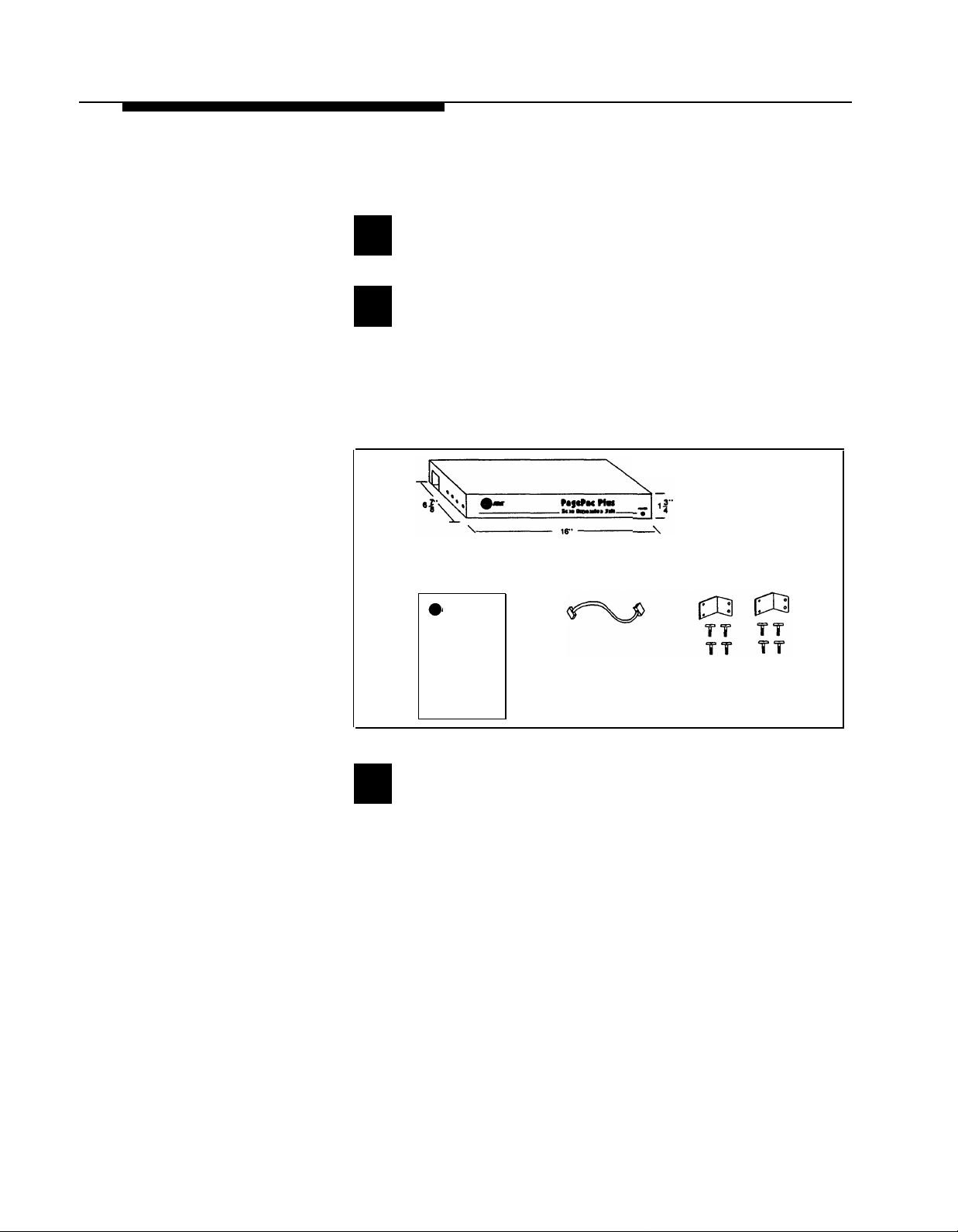
Check Shipping Container Contents
Zone Expansion Unit
Mounting hardware (screws and brackets)
Cable, 8-pin Molex
This Installation and Use guide
INSTALLATION GUIDE
AT&T
PagePac Plus
Zone Expansion Unit
Installation and Use
8-PIN MOLEX CABLE
ZONE EXPANSION UNIT
MOUNTING BRACKETS
Figure 1. Zone Expansion Unit Components
3
Have Required Tools
The following tools are required for the installation of the system
hardware and cabling.
■
Phillips screwdriver (small and large)
■
Standard blade screwdriver (small and large)
■
Wire strippers (24 AWG - 12 AWG)
■
Telephone test set (optional, for troubleshooting)
■
Tone out circuit tester (optional, for troubleshooting)
Portable 70V speaker (use cabling pulled for ceiling speakers)
■
(optional, for troubleshooting)
■
Volt-Ohm Meter (optional, for troubleshooting)
■
4 wood screws, if mounting on wall
3
Page 4
Installation Steps
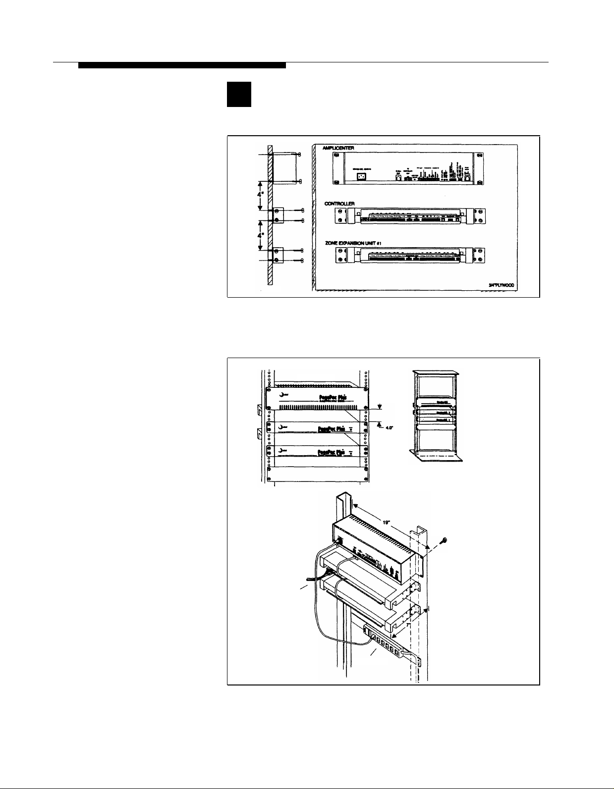
NOTE: When installing the
Zone Expansion Unit, leave at
least four inches space above
and below for proper ventilation.
Install the paging equipment in
a ventilated room where there
is easy access to speaker
cabling (preferably in the
telephone equipment room).
1
Mount the Zone Expansion Unit(s) (Z.E.U.) to either a
wall, cabinet or a rack (below the Controller).
SIDE VIEW
Figure 2. Wall Mounted Hardware
FRONT DETAIL
REAR DETAIL
ZONE
WIRING
POWER STRIP
Figure 3. Rack Mounted Hardware
TYPICAL
COMBINATION
PAN HEAD
PILOT POINT
# 12 - 24 (TYPICAL)
4
Page 5

2
Connect 8-pin Molex from Controller to first Zone
Expansion Unit, and next Z.E.U.’s, if used.
NOTE: Up to 3 Zone
Expansion Units can be used,
providing up to 56 paging
and/or control zones.
CONTROLLER
POWER, CONTROL, 70V AUDIO
ZONE EXPANSION UNIT #1
POWER, CONTROL, 70V AUDIO
TO NEXT ZONE EXPANSION UNIT(S)
Figure 4. 8-pin Molex Connector from Controller to Zone Expansion Unit(s)
3
Set DIP switches on each Zone Expansion Unit(s).
ON 1ST ZONE EXPANSION UNIT SET DIP SWITCH TO:
ON
ENABLES
ZONES 9-24
ON 2ND ZONE EXPANSION UNIT SET DIP SWITCH TO:
ON 3RD ZONE EXPANSION UNIT SET DIP SWITCH TO:
Figure 5. Setting Zone Expansion Unit DIP Switches
ENABLES
ON
ON
ZONES 25-40
ENABLES
ZONES 41-56
5
Page 6

4
Set the Zone Option switches on the Controller and
Zone Expansion Unit(s).
NOTE: For each zone used, no
matter what its function, this
switch needs to be set to one
of three settings for proper
zone operation.
The Controller has eight
switches for zones 1-8. Each
subsequent Zone Expansion
Unit has switches for zones
9-24, 25-40, and 41-56.
Refer to the Zone Map and
Zone Configuration Tables
filled out during facility paging
system design. You can find
these in the PagePac System
Installation and Configuration
Guide.
Figure 6. Setting Zone Option Switches on Controller and Zone Expansion Units
Connecting Speakers
SPEAKER SETTING
CONTACT
CLOSURE OUTPUT
CONTACT
CLOSURE INPUT
70V AUDIO OUTPUT
SHIELDED FOR
TALKBACK
SIGNAL-IN SETTING
CONTACT
CLOSURE OUTPUT
CONTACT
CLOSURE INOUT
70V AUDIO OUTPUT
ZONE 2
MOMENTARY
CONTACT CLOSURE
CONTACT CLOSURE SETTING
ZONE OPTION SWITCHES
CONTACT
CLOSURE OUTPUT
CONTACT
CLOSURE INPUT
70V AUDIO OUTPUT
ZONE 2
ZONE EXPANSION UNIT
MOMENTARY OFF
MOMENTARY ON
RELAY POWER
CONTROLLER
NOTE: Adjust all speakers per
volume and power
requirements as noted on floor
plan, during or after installation.
Figures 8 and 9, on the
following pages, show wiring
methods using local and zone
connector blocks, and contact
closure zone applications.
6
5
Locate and mount all speakers in accordance with the
floor plan drawing for this installation.
6
Connect each speaker to the appropriate Home Run
or Speaker-to-speaker wiring scheme as shown on the
floor plan.
70 VOLT
AUDIO
OUTPUT
Figure 7. Speaker Wiring Methods
SPEAKER-TO-SPEAKER METHOD
HOME RUN METHOD
Page 7

OR ZONE EXPANSION UNIT’S ZONE CONNECTORS
DO NOT
OVERTIGHTEN
SCREW OVER
WIRE
SHIELD TO
SPEAKERS OR
ZONE CLOSURES
24 TO 22 AWG
WIRE TO
CONNECTOR
TYPICAL CONNECTIONS FOR CONTROLLER
CONTACT
CLOSURE OUTPUT
CONTACT
CLOSURE INPUT
70v OUTPUT
LABEL
ZONE 5
ZONE 6
ZONE 1
SHIELDED
SCREW LUG
TERMINAL BLOCK
A LARGER GAUGE WIRE
MAY BE REQUIRED FOR
HIGH POWER OR VERY
LONG CABLE RUNS (500’ PLUS)
66 OR 110 TYPE
CONNECTOR
BLOCK
ZONE SWITCH
CLOSURE
ZONE SWITCH
CLOSURE INPUT
SHIELD
SPEAKER
ZONES
LIMITED
NUMBER OF
SPEAKERS
PER ZONE
SCREW LUG
TERMINAL BLOCK
AT&T 66E OR 110
Figure 8. Zone Wiring Using Connector Blocks
LABEL ALL ZONE
BLOCKS FOR EASE
OF INSTALLATION
MULTIPLE SPEAKERS
SINGLE ZONE
(TYPICAL)
7
Page 8

ZONE 2
ZONE 1
TYPICAL ZONE CONNECTIONS FOR
ZONE EXPANSION UNIT
INPUT-CONTACT
CLOSURE
CONTACT
CLOSURE OUTPUT
CONTACT
CLOSURE INPUT
70V OUTPUT
TERMINAL
CONNECTIONS USE
22 TO 24 AWG
DOOR
ENTRANCE
POWER
LOCK
MECHANISM
OUTPUT-CONTACT
CLOSURE (MOMENTARY)
DOORBELL
USE TERMINAL BLOCKS AS
ILLUSTRATED IN FIGURE 8
LABEL ALL TERMINAL BLOCKS
BY ZONE # AND APPLICATION.
SHIELDED
CABLE
70V ZONE
OUTPUT
AUDIO WITH
TALKBACK
CONTACT
CLOSURE
INPUT FROM
PUSHBUTTON
INPUT-CONTACT
CLOSURE
DOOR SPEAKER PHONE
Figure 9. Contact Closure Zone Wiring to Zone Expansion Units and Controller
8
FIRE ALARM
SYSTEM
SECURITY
ALERT
Page 9

7
Measure the resistance of each home run wiring with an ohmmeter.
Any pair indicating a value of less than 15 ohms must be rechecked
for possible shorted wiring or speakers. Correct any problems and
retest.
Test speaker wiring for short circuits
NOTE: DO NOT over tighten
zone connector screws.
CAUTION: A 70V audio output
setting going to other than
speakers may damage other
equipment
The zone connectors on the Controller and Zone Expansion Units can
accommodate up to two 22 AWG wires or four 24 AWG wires per zone
output. Check zone option switch setting with Zone Map and Zone
Configuration Tables as you connect each zone.
Powering Up System
With all zones wired and connected to the Controller and Zone
Expansion Unit(s), initial testing can begin. Once initial testing is done,
you can begin to program the Controller with the features for each zone.
NOTE: If during power up, the
system does not respond as
described, refer to the
Troubleshooting section of this
guide, and/or the PagePac
Plus System Installation and
Configuration Guide for
detailed troubleshooting.
8
9
Make zone connections to Controller and Zone
Expansion Units. (See Figures 6 thru 8.)
Plug the power cord into the A.C. input connector on
the AmpliCenter. The following should happen.
The green Power LED on the AmpliCenter will turn on
1.
and stay on.
2.
The green Page Access LED on the AmpliCenter also
turns on, but will go out after a few seconds.
On the Controller, verify that the green Phone System
3.
Enabled LED if off.
4.
On the Controller, verify that the yellow Attendant
Access Enabled LED is off.
5.
The green Power LED on the Zone Expansion Unit(s)
will turn on and stay on.
10
A quick reference card for telephone programming, along with detailed
programming instructions, can be found in the PagePac Plus System
Installation and Configuration Guide, programming section on page 29.
Begin programming the Controller
9
Page 10

Troubleshooting
Some common problms encountered when the paging system is not
operating are described below. Check each item in the order listed.
No AC power to AmpliCenter or Controller (They supply power to1.
the Zone Expansion Units)
Host telephone system failure
2.
Host system page port failure
3.
A hardwire disconnect between host system and the Controller
4.
AmpliCenter, Controller, or Zone Expansion Unit zone switches or
5.
DIP switch settings tampered with
If the problem has not been resolved by checking the preceding items,
refer to the Troubleshooting tables in the PagePac Plus Installation and
Configuration Guide.
Controls and Indicators, Terminals and Connectors
Figure 10 shows the controls and indicators, terminals and connectors on
the rear panel of the Zone Expansion Units. Table 1 identifies them by
function.
Figure 10. Zone Expansion Unit Back Panel.
Table 1. Controls and Indicators, Terminals and Connectors
1.
2.
3.
4.
5.
Zone option 3-position slide switch: 70V audio out, contact closure input, contact closure output
Zone connector for expansion zones: plus, minus, and ground screw terminals
8-pin Molex connector from controller: power, control, and audio or previous Zone Expansion Unit
8-pin Molex connector to additional Zone Expansion Unit: power, control, and audio
DIP switch to be set when one, two, or three Zone Expansion Unit(s) are used.
ZONE EXPANSION UNIT
10
Page 11

Controller Specifications
Table 2 describes the technical specifications of the Zone Expansion Unit.
Table 2. Zone Expansion Unit Specifications
Each Zone Expansion Unit connects up to 16 zones of audio output (including talkback),
Capacities
Dimensions and
Weight
Electrical
Relay Contacts
Temperature
Range:
Humidity Range:
Altitude:
Environmental
Interconnect
Cable
■
contact closure outputs or inputs.
Height: 1.75 inches (4.4 cm).
■
■ Width: 16 inches (40.64 cm) without brackets, 19 inches (48.3 cm) with brackets attached.
■
Depth: 6.875 inches (17.5 cm).
■
Weight: 3 pounds (6.6 kg).
■
Control Contact Closure: Contacts are rated at 120VAC/50VDC at 1 amp.
■
Audio Zone: Contacts are rated at 2 amps.
■ 0 to +40 deg. C. (32 to 104 deg. F.) operational.
■
–40 to +66 deg. C. (–40 to +150 deg. F.) storage and shipment.
■
5% to 95% (non-condensing) storage/shipment and operation.
■
Sea level to 10,000 ft. operational (1048 to 648 millibars) 40,000 ft. max. shipment.
■ Locate in an area free of excess moisture, corrosive gases, dust, and chemicals.
■
8-position, 5 amp contact rating, locking, keyed, 22 AWG wire, housing material 94V–2,
providing 70.0 Vrms (4), common ground, +17 VDC, Serial Data and Clock Data.
11
Page 12

© 1994 AT&T
All rights reserved
Printed in U.S.A.
CIC#463-248-203
0II722590-002
Issue 3, October 1994
 Loading...