

Page 1

AT&T
AT&T System 25
Installation and
Maintenance Manual
555-540-103
B
November 1995
Page 2

©1989 AT&T
All Rights Reserved
Printed in USA
TO ORDER COPIES OF THIS DOCUMENT REFER TO DOCUMENT NUMBER
555-540-103
Contact: Your AT&T sales representative, or
Call: 800-432-6600, Monday through Friday between 7:30 am
and 6:00 pm EST, or
In Canada call: 800-255-1242
Write: AT&T Customer Information
2855 North Franklin Road
P.O. Box 19901
Indianapolis, Indiana 42619
Every effort was made to ensure that
complete and accurate at the time of
subject to change. This document will
changes.
Center
the information in this document was
printing.
However, this information is
be reissued periodically to incorporate
Installation and Maintenance Manual
Prepared by System 25
Document Development Group and the
AT&T Documentation
Management Organization
Page 3

DANGER
Do not open the fan assembly or remove rear cabinet cover before
unplugging the cabinet from the electrical outlet. Wait at least five
minutes after unplugging the power cord before removing the rear
cover or power supply. The AT&T System 25 cabinets are not user
serviceable. Some voltages inside the cabinets are hazardous.
This equipment is to be serviced only by qualified technicians.
CUSTOMER WARNING
The Installation and Maintenance Manual is designed for use by
qualified service technicians only. Technician qualification includes
completion of an AT&T hands-on instructor-led course covering
installation and maintenance for this product. The use of these
documents by anyone else might void the warranty. Hazardous
electrical voltages are present inside this product.
SERVICE TECHNICIAN WARNING
1. Never install telephone wiring during a lightning storm.
2. Never install telephone jacks in wet locations unless the
is specifically designed for wet locations.
3. Never touch uninsulated telephone wires or terminals un
jack
less the
telephone line has been disconnected at the network interface.
4. Use caution when installing or modifying telephone lines.
a
Page 4
THE FOLLOWING SYMBOLS AND PICTOGRAPHS
APPEAR ON THE EQUIPMENT
SYMBOL
The exclamation point
within an equilateral
triangle is intended
to alert the user to
the presence of
important operating
and maintenance
(servicing) instructions
ELECTRICAL SHOCK
Warns of the danger
of electrical shock
from hazardous voltages
present within the
control unit
Warns of the risk of
fire if the air filter
is not in place
b
Page 5

FCC NOTIFICATION AND REPAIR INFORMATION
AT&T SYSTEM 25
This telephone equipment is registered with the Federal Communications
Commission (FCC) in accordance with Part 68 of its Rules. In compliance with
the Rules, be advised of the following:
MEANS OF CONNECTION
Connection of this telephone equipment to
the nationwide telecommunications
network shall be through a standard network interface USOC RJ21X jack.
Connection to private line network channels requires USOC RJ2GX jack for tie
lines or USOC RJ21X jack for off-premises station lines. Connection to T1
facilities requires USOC RJ48X or RJ48C jack. These can be ordered from your
telephone company.
NOTIFICATION TO THE TELEPHONE COMPANY
If the system is to be connected to off-premises stations (OPSs), you must notify
the telephone company of the OPS class of service, OL13C, and the service
order code, 9. OF. For R3 systems, the Analog service order code is 9.0Y, the
Digital service order code is 6.0Y.
Upon the request of the telephone company, inform them of the following:
— The Public Switched Network “lines” and the Private “lines” to which
you will connect the telephone equipment.
— For private line connections, provide the facility interface code, TL31M
for tie lines. You must also specify the service order code, 9.0F or 9.0Y
for R3 systems.
Customer instructions will advise the customer to provide the telephone
company with the registration number (either -MF or -KF, depending on
the application of the system) and the ringer equivalency number (REN)
from the label on the equipment. In addition, customer will be advised
c
Page 6

that certification in writing may be required when an existing
multifunction system is being reconfigured as a Key system, if the
customer desires the lower rate.
— For Digital connections with D4 Framing Format provide the Facility
interface code 041DU9-B, for digital connections with Extended Framing
Format, provide the Facility interface code 04DU9-C. You must also
specify the service order code, 6.0Y.
— The quantities and USOC numbers of the jacks required.
— For each jack, provide the sequence in which lines are to be connected;
the type lines and the facility interface code and the ringer equivalence
number by position, when applicable.
This telephone equipment should not be used on coin telephone lines.
Connection to party line service is subject to state tariffs.
REPAIR INSTRUCTIONS
If you experience trouble with this telephone equipment, contact the AT&T
Business Customer Service Center on 1-800-242-2121. The telephone company
may ask that you disconnect this equipment from the network until the problem
has been corrected or until you are sure that this equipment is not
malfunctioning.
System 25 troubles that must be escalated to a higher level of maintenance
should be referred to the National Service Assistance Center on 1-800-628-2888.
RIGHTS OF THE TELEPHONE COMPANY
If your telephone equipment causes harm to the telephone network, the
telephone company may discontinue your service temporarily. If possible, they
will notify you in advance. But if advance notice isn’t practical, you will be notified
as soon as possible. You will be informed of your right to file a complaint with the
FCC.
d
Page 7

Your telephone company may make changes in its facilities, equipment,
operations, or procedures that could affect the proper functioning of your
equipment. If they do, you will be notified in advance to give you an opportunity
to maintain uninterrupted telephone service.
HEARING AID COMPATIBILITY
The voice terminals described in this manual are compatible with inductively
coupled hearing aids as prescribed by the FCC.
FCC INFORMATION
FCC REGISTRATlON lNFORMATlON
Registration Number
AS593M-71565-MF-E
Ringer Equivalence
0.5A
Network Interface
RJ21X, RJ2GX or RJ48X
PRIVATE LINE SERVICE
Service Order Code
● Analog
9.0F
● Analog (R3)
9.0Y
●
Digital (R3)
I
6.0Y
Facility Interface Code
●
Tie Lines
TL31 M
● Off-Premises Stations
OL13C
● Digital D4 Framing
04DU9-B
●
Digital ESF
04DU9-C
November 1995
Page 8

FCC WARNING STATEMENT
Federal Communicatlons Commission (FCC) Rules require that you be notified of
the following:
This equipment generates, uses, and can radiate radio frequency energy and, if
not installed and used in accordance with the instruction manual, may cause
interference to radio communications.
It has been tested and found to comply with the limits for a Class A computing
device pursuant to Subpart J of Part 15 of FCC Rules, which are designed to
provide reasonable protection against such interference when operated in a
commercial environment.
Operation of this equipment in a residential area is likely to cause interference
in which case the user at his or her own expense will be required to take
whatever measures may be required to correct the interference.
SECURITY OF YOUR SYSTEM-PREVENTING TOLL FRAUD
As a customer of a new telephone system, you should be aware that there exists
an increasing problem of telephone toll fraud. Telephone toll fraud can occur in
many forms, despite the numerous efforts of telephone companies and telephone
equipment manufacturers to control it. Some individuals use electronic devices
to prevent or falsify records of these calls. Others charge calls to someone else’s
number by illegally using lost or stolen calling cards, billing incorrect parties,
clipping on to someone else’s line, and breaking into someone else’s telephone
equipment physically or electronically. In certain instances, unauthorized
individuals make connections to the telephone network through the use of remote
access features.
The Remote Access feature of your system, if you chose to utilize it, permits offpremises callers to access the system from a remote telephone by using an 800
number or a 7- or 10- digit telephone number. The system returns an
acknowledgement signaling the user to key in his or her authorization code,
which is selected and administered by the system manager. After the
authorization code is accepted, the system returns dial tone to the user. If you do
not program specific egress restrictions, the user will be able to place any call
Page 9

normally dialed from a telephone associated with the system. Such an offpremises network call is originated at, and will be billed from, the system location.
The Remote Access feature, as designed, helps the customer, through proper
administration, to minimize the ability of unauthorized persons to gain access to
the network. Most commonly, phone numbers and codes are compromised
when overheard in a public location, through theft of a wallet or purse containing
access information, or through carelessness (writing codes on a piece of paper
and improperly discarding it). Additionally, hackers may use a computer to “dial”
an access code and then publish the information to other hackers. Enormous
charges can be run up quickly. It is the customer’s responsibility to take the
appropriate steps to properly implement the features, evaluate and administer the
various restriction levels, protect access codes, and distribute access codes only
to individuals who have been fully advised of the sensitive nature of the access
information.
Common carriers are required by law to collect their tariffed charges. While
these charges are fraudulent charges made by persons with criminal intent,
applicable tariffs state that the customer of record is responsible for payment of
all long-distance or other network charges. AT&T cannot be responsible for such
charges and will not make any allowance or give any credit for charges that result
from unauthorized access.
To minimize the risk of unauthorized access to your communications system:
● Use a nonpublished Remote Access number.
● Assign authorization codes randomly to users on a “need-to-have”
basis, keeping a log of ALL authorized users and assigning one code
per person.
● Use random sequence authorization codes, which are less likely to be
broken.
● Deactivate all unassigned codes promptly.
● Ensure that Remote Access users are aware of their responsibility to
keep the telephone numbers and any authorization codes secure.
● When possible, restrict the off-network capability of off-premises callers,
via use of Call Restrictions and Disallowed List capabilities.
Page 10

● When possible, block out-of-hours calling.
● Frequently monitor system call detail reports for quicker detection of any
unauthorized or abnormal calling patterns.
● Limit Remote Call Forward to persons on a “need-to-know” basis.
Page 11

Contents
INTRODUCTION
FCC PRECAUTIONS
INSTALLATION
TOOLS AND TEST EQUIPMENT
CROSS-CONNECT EQUIPMENT DESCRIPTION
Trunk Access Equipment
700A-110-BI -25 or 700A-66-B1-25 Cut-Down Jack
108 Emergency Transfer Unit (ETU)
Station Interconnect Panel (SIP)
617A Panel
Adapters
Fanning Strip
Cables
Splitter Cables
Octopus Cables
853B Adapter Cable
DS1 Connector Cables
Cable Labels
Symbols Used in Figures
PREINSTALLATION REQUIREMENTS
Table and Backboard
Network Interface
AC Power
Grounding
Lightning Protection
Secondary Protection
Building Wiring
INSTALL SYSTEM CABINETS
Position Cabinet(s)
Check Cabinet Contents
Required Circuit Pack Positions
Label Connectors on Back Cover
Install 4A Retainer Clips
Connect Cabinet
1-1
1-2
2-1
2-2
2-3
2-4
2-4
2-4
2-6
2-6
2-8
2-10
2-11
2-11
2-12
2-12
2-12
2-13
2-15
2-16
2-16
2-16
2-18
2-18
2-19
2-21
2-22
2-23
2-23
2-23
2-28
2-28
2-29
2-30
Page 12

TDM Bus Connections.
Ground Wire Connections.
POWER UP AND INITIALIZE SYSTEM
Connect Power
Connect Administration Equipment
Cold Start the System
Check Performance of Cabinet Components
Report Problems
Initialize System
INSTALL CROSS-CONNECT EQUIPMENT
Install TAE, 617A Panels, and Fanning Strips
Mount 858A orZ210A2 Adapters
INSTALL MODULAR BULK POWER SUPPLY
(Optional)
INSTALL EQUIPMENT ROOM TRUNK CABLING
Connect Network Interfaces to TAE Blocks
Connect Cabinets to TAE Blocks
Connect Ground Start, Loop Start, and DID Trunks
Connect Tie Trunks
Install DS1
Connect S25 to Another On Premises PBX
Off Premises Metallic (Cable) Connections
Off Premises Non Metallic Connections
Install Customer Service Unit (CSU)
Line Compensation/Equalization
Connect Coupled Bonding Conductor (CBC)
INSTALL EQUIPMENT ROOM STATION CABLING
Connect Building Wiring to SIP
Modular Plug Termination
4-Pair Cable Terminations
Connect Cabinets to SIP
Prepare Carrier Loading Labels
Modify Octopus Cables if Required
Make SIP Connection for CPU/Memory
Make SIP Connections to Cabinet for 7300H Series
Terminals
Make SIP Connections to Cabinet for MET Sets
Make SIP Connections to Cabinet for Single-Line Sets
2-30
2-33
2-33
2-33
2-34
2-35
2-39
2-42
2-43
2-43
2-44
2-47
2-49
2-49
2-49
2-51
2-51
2-52
2-53
2-53
2-56
2-56
2-57
2-58
2-58
2-60
2-62
2-62
2-64
2-66
2-67
2-69
2-71
2-73
2-74
2-74
-ii-
Page 13

Make SIP Connections for Data Terminals and
Computers
Make SIP Connections to Cabinet for ATL Cordless
Telephones
Perform SIP Housekeeping
INSTALL
EMERGENCY TRANSFER UNITS (ETUs)
Make Emergency Transfer Connections
Install Ground-Start Key
INSTALL ATTENDANT
CONSOLE
INSTALL TERMINALS
Label Terminals
Stand-Alone Voice Terminals
Stand-Alone Remotely Powered Voice Terminals
Single-Line and 7300H Series Voice Terminals With
Associated ADUs
ATL Cordless Telephone
Off-Premises Stations (TN742)
Out-of-Building Voice Terminals (TN742)
Out-of-Building Voice Terminals (ZTN79)
Off-Premises—
DS1 lnterface
Stand-Alone Data Terminals
ADU Connections
MADU Connections
INSTALL CUSTOMER’S
SAT
Nonswitched Connection of Equipment Plugged Into
System AC Outlet
Nonswitched Connection of Equipment
On-Premises Digital Switched Connection
Off-Premises Nonswitched Connection
Off-Premises Switched Connection
INSTALL CUSTOMER’S DTU
INSTALL STATION MESSAGE DIGITAL RECORDING
(SMDR) EQUIPMENT
INSTALL STARLAN NETWORK INTERFACE
Shared System 25 Voice/STARLAN NETWORK Data
Connections
Single-Line Voice Terminals
2-75
2-76
2-76
2-77
2-80
2-82
2-83
2-87
2-88
2-90
2-91
2-92
2-94
2-95
2-95
2-96
2-96
2-98
2-98
2-101
2-102
2-102
2-104
2-106
2-109
2-109
2-111
2-111
2-112
2-113
2-113
-III-
Page 14

7300H Series Voice Terminals
INSTALL MUSIC-ON-HOLD INTERFACE
FCC-Registered Music Source Interface
Non-FCC Registered Music Source Interface
INSTALL EXTERNAL ALERTS
INSTALL RECORDED DELAY ANNOUNCEMENT
2-115
2-117
2-117
2-119
2-120
2-121
2-121
2-121
2-122
2-124
2-128
INSTALL DICTATlON SYSTEM INTERFACE
INSTALL PAGING SYSTEM INTERFACE
Direct Connection to TN763 Auxiliary Trunk CP
Connection to TN763 Auxiliary Trunk CP (278A
Adapter Required)
Connection to ZTN76 or ZTN77 CP
SYSTEM TESTS
TEST OUTGOING TRUNKS
TEST DS1 INTERFACE.
TEST INCOMING DID TRUNKS
TEST INCOMING TIE TRUNKS
TEST 7300H SERIES VOICE TERMINALS
TEST SINGLE-LINE VOICE TERMINALS
TEST ATL CORDLESS TELEPHONE
TEST DIAL ACCESS CODES
TEST SYSTEM FEATURES
ARS and SMDR Tests
DGC Test
System Speed Dialing Test
PDC Login Test
Call Coverage Test
TEST ATTENDANT CONSOLE
TEST SELECTOR CONSOLE
3-1
3-1
3-1
3-2
3-2
3-3
3-5
3-6
3-6
3-6
3-6
3-7
3-7
3-8
3-8
3-9
3-9
TEST DATA TERMINAL DIALING FEATURE
3-10
-iv-
Page 15

MAKE POOLED MODEM TEST CALL
. . . .
TEST TRANSFER TO DATA . . . . ... . . .
TEST
EXTERNAL ALERT (NIGHT SERVICE)
TEST
TEST
TEST
TEST
TEST
3-11
3-11
3-12
DICTATION SYSTEM ACCESS
3-13
PAGING INTERFACE
MUSIC-ON HOLD
EMERGENCY TRANSFER
TOUCH-TONE RECEIVERS
3-13
3-14
3-15
3-16
MAINTENANCE
4-1
EQUIPMENT NEEDED
Precautions
GENERAL INFORMATION
System Errors and Alarms
Emergency Transfer
Circuit Pack LEDs
Attendant Console LED
Power Supply
Switches and Test Points
System Administration
Remote Initialization Maintenance (RIM) Service
4-4
4-4
4-4
4-4
4-6
4-6
4-6
4-6
4-6
MAINTENANCE STRATEGY
Total System Failures
Port Problems
Common Control Problems
Staion, Trunk Problems
Antomatic Maintenance Tests
Maintenance Failure
4-9
4-11
4-11
4-12
4-13
4-13
4-13
USING THE DIGITAL TAPE UNIT
Setting Up the DTU
Saving Translations
Verifying Translations
Restoring Translations
4-14
4-14
4-15
4-16
4-18
-v-
Page 16

ROUTINE MAINTENANCE
Reseating and Replacing Circuit Packs
Removing and Restoring Power
Restarting the System
ERROR LOG
Accessing the Error Log From the SAT
ERROR MESSAGES
Clearing System-Detected Troubles
Complete System Failure
Common Control Trouble
Circuit Pack Trouble
Frontplane Ribbon Connector Trouble (Release 1
Only)
Power Supply Trouble
Power Supply Protection
Power Supply Replacement
Fan Assembly Trouble
Overheating Trouble
Backplane and Cabinet Trouble
Emergency Transfer Unit Trouble
CLEARING USER-DETECTED TROUBLES
Administration Equipment Troubles
Time-Keeping Troubles
Voice Terminal and Wiring Troubles
Voice Transmission Troubles
7300H Series Terminal Troubles
Virtual Facilities Troubles
Trunk Troubles
Outgoing Trunk Problems
Incoming Trunk Problems
Error Log Interpretation: Loop-Start Trunks
Error Log Interpretation: Ground-Start Trunks
DID Trunks Troubles
Switched
Loop Attendant Console Troubles
Special Port Circuit Options for Stations and Trunks
Data Line Troubles
Multiple Troubles or Trouble That Cannot Be
Diagnosed
4-20
4-20
4-22
4-23
4-27
4-30
4-32
4-61
4-61
4-61
4-63
4-64
4-64
4-69
4-70
4-71
4-72
4-72
4-80
4-81
4-81
4-82
4-82
4-83
4-84
4-85
4-89
4-89
4-90
4-90
4-91
4-92
4-93
4-99
4-100
4-102
-vi-
Page 17

REFERENCES
ABBREVIATIONS AND ACRONYMS
5-1
6-1
A-1
APPENDIX A: System Wiring
Connector Pin Assignments
System 25 Building Wiring
APPENDIX B: Parts Listing
Tables
A-1
A-1
B-1
APPENDIX C: System Additions or Changes
Evaluate Cabinet Unit Power Load
Add Circuit Pack
Add Cabling
Set Option Switches on TN760B CP
Replace Circuit Pack
Add Cabinet
Add Termina
Add Trunk
Add Trunk—DSl
Interface
Replace Voice-Only Terminal With Voice/Data
Terminal
Add Pooled Modem Circuit Pack
Add
Auxiliary Equipment
APPENDIX D: System Upgrades
APPENDIX E: Administration Codes and Data
Default Dial Code Assignments
C-1
C-1
C-2
C-3
C-5
C-7
C-8
C-10
C-11
C-11
C-12
C-13
C-13
D-1
E-1
E-1
-vii-
Page 18

APPENDIX F: Administration Error Messages
GLOSSARY
INDEX
F-1
G-1
I-1
-viii-
Page 19

Figures
Figure 2-1.
Figure 2-2.
Figure 2-3.
Figure 2-4.
Figure 2-5.
Figure 2-6.
Figure 2-6a.
Figure 2-7.
Figure 2-8.
Figure 2-9.
Figure 2-10.
Figure 2-11.
Figure 2-12.
Figure 2-13.
Figure 2-14.
Figure 2-15.
Figure 2-16.
Figure 2-17.
Figure 2-18.
Figure 2-19.
Figure 2-20.
Figure 2-21.
Figure 2-22.
Figure 2-23.
Figure 2-24.
Figure 2-25.
Figure 2-26.
Figure 2-27.
Figure 2-28.
Figure 2-29.
Figure 2-30.
Figure 2-31.
Figure 2-32.
Figure 2-33.
Figure 2-34.
Figure 2-35.
Figure 2-36.
10 BEAU
617A Panel
SIP Adapters
50A Fanning Strip
Splitter Cables
Octopus Cable
853B Adapter Cable
Cable Labels
Typical System 25 Floor Plan
AC Power Distribution—Multiple Cabinet System
Three-Cabinet System, Front View With Covers
Removed
Position of Shorting Plugs on CPU/Memory Circuit
Pack . . . . . . . . . . . . . . . .
4A Retainer Clip Installation
TDM Bus Terminations (Rear View of 3-Cabinet
System)
Temporary SAT and DTU Connections
Typical System 25 Port Circuit Pack
SIP and TAE Backboard Layout
Alternate SIP and TAE Backboard Layout
Mounting Adapters
Direct Connection (Side by Side)
Direction Connection (Side by Side)
DS1 Connections—1311 to 4310 Feet
DS1 mnnections4311 Feet or More
DS1 Connections–Off Premise Cabling
DS1 Connections-Non Metallic Connections
CSU Connections
Voice and Data Station Records Form (Example
Entered)
Modular Plug Terminations Connected to the SIP
Cut Down Terminations Connected to the SIP
Carrier Loading Label
Standard and Modified Octopus Cables
Mounting Octopus Cable on Fanning Strip
10B Emergency Transfer Unit
Emergency Transfer Unit Connections
Ground Start Key Installation
Attendant Console With DXS Console
Remotely Powered DXS Console Connection
2-5
2-7
2-9
2-10
2-11
2-12
2-12
2-14
2-17
2-21
2-26
2-27
2-29
2-32
2-34
2-42
2-45
2-46
2-48
2-54
2-54
2-55
2-55
2-56
2-57
2-58
2-61
2-63
2-65
2-68
2-70
2-72
2-78
2-79
2-82
2-84
2-86
November 1995
-ix-
Page 20

Figure 2-37.
Figure 2-38.
Figure 2-39.
Figure 2-40.
Figure 2-41.
Figure 2-42.
Figure 2-43.
Figure 2-44.
Figure 2-45.
Figure 2-46.
Figure 2-47.
Figure 2-48.
Figure 2-49.
Figure 2-50.
Figure 2-51.
Figure 2-52.
Figure 2-53.
Figure 2-53a.
Figure 2-54.
Figure 2-55.
Figure 2-55a.
Figure 2-56.
Figure 2-57.
Figure 2-58.
Figure 2-59.
Figure 4-1.
Figure 4-2.
Figure 4-3.
Figure 4-4.
Figure 4-5.
Figure 4-6.
Figure 4-7.
Stand-Alone Voice Terminal Connections 2-90
Stand-Alone Remotely Powered Voice Terminal
Connections
2-91
Single-Line Terminal/ADU Connections 2-93
7300H Series Terminal/ADU Connections 2-94
DS1 to D4 Connections for Off-Premises Stations 2-97
Local Powering of an ADU
2-99
Remote Powering of an ADU (Optional) 2-100
MADU to Host Computer or Terminals Connections 2-101
Nonswitched Connection of Peripheral Equipment
Plugged Into System AC Outlet
2-103
Greater Than 50 Feet and/or Not Sharing Same
AC Outlet
2-105
On-Premises Peripheral Equipment With Switched
Connection to CPU/Memory 2-108
Off-Premises Peripheral Equipment With Direct
Connection to CPU/Memory
2-110
ZTN84 STARLAN Interface CP Connection 2-112
Single-Line Analog Terminal/STARLAN
NETWORK Workstation Connections
2-114
7300H Series Terminal/STARLAN NETWORK
Workstation Connections
2-116
Music Source, FCC Registered
2-118
Music Source, Non-FCC Registered
2-119
Music-on-Hold
2-119a
External Alerts
2-120
Paging System Connection to TN763 Circuit Pack 2-123
Loudspeaker Paging with Background
Music
2-124a
Paging System Connection to TN763 Circuit Pack
(278A Adapter Required)
2-126
278A Adapter Plug Positions for Connecting TN763
Circuit Pack to Paging System
2-127
PagePac 20 System Connection to ZTN76 or
ZTN77 Circuit Pack
2-129
Paging System Connection to ZTN76 or ZTN77 2-131
Response to System 25 Trouble Report
4-10
Clearing Power Supply Troubles (Sheet 1 of 4-47
Clearing CO Trunk Troubles
4-49
Clearing 4-Wire Tie Trunk Troubles (Sheet 1 of 4) 4-50
Clearing STARLAN Interface Troubles
4-54
Clearing Tie Trunk Troubles (Sheet 1 of 5) 4-55
Clearing Paging Equipment Troubles 4-60
-x-
November 1995
Page 21

Figure 4-8.
Figure 4-9.
Figure 4-10.
Figure 4-11.
Figure 4-11.a.
Figure 4-12.
Figure 4-13.
Figure C-1.
Figure C-2.
Figure C-3.
Table 2-A.
Table 2-B.
Table 2-C.
Table 2-D.
Table 2-E.
Table 2-F.
Table 4-A.
Table 4-B.
Table 4-C.
Table 4-D.
Table 4-E.
Table 4-F.
Table A-A.
Table A-B.
Table A-A.
Table A-B.
Table C-A.
Table C-B.
Table E-A.
Table E-B.
AC Power Schematic
4-68
System Cabinet Backplane Wiring Side (Sheet 1
of 2)
4-73
TDM Signal Destinations on Cabinet Backplane 4-75
Power Designations on Cabinet Backplane 4-76
853 Adapter
4-79a
Clearing Virtual Facilities Troubles (Sheet 1 of 3) 4-86
Clearing Switched Loop Attendant Console
Troubles (Sheet 1 of 5)
4-94
Typical System 25 Port Circuit Pack
C-4
Tie Trunk (TN760B) Circuit Pack Option Switches C-5
DS1 Network Interface Connections
C-12
Tables
Tools and Test Equipment Required for
Installation
2-2
Circuit Packs, Their Functions, and Protectors 2-24
Displayed SAT Messages During Cold or Warm
Restart
2-37
Circuit Pack LED Status Indications
2-40
Circuit Pack Versus Terminal Type 2-66
Feature Button Abbreviations and Lables 2-88
Displayed SAT Messages During Cold or Warm
Start 4-25
Power Supply Test Points
4-65
Circuit Pack Voltages—Symptoms
4-66
25-Pair Connector to Backplane Designations 4-78
Station/Trunk/Special Port Circuit Pack Options 4-99
Applicable Actions for Circuit Pack Options 4-
100
25-Pair Connector Pin Assignments
A-2
Building Wiring
A-4
25-Pair Connector Pin Assignments
A-2
Building Wiring
A-4
Unit Loads C-2
TN760B Option Switch Settings and
Administration
C-6
Default Dial Codes
E-1
PORT/PD. Administration, Voice Terminals
(Menu=1/2)
E-2
November 1995
-xi-
Page 22

Table E-C.
Table E-D.
Table E-E.
Table E-F.
Table E-G.
. .
Table E-H.
Table E-1.
Table E-J.
Table E-K.
Table E-L.
Table E-M.
Table E-N.
Table E-0.
Table E-P.
Table E-Q.
Table E-R.
Table E-S.
Table E-T.
Table E-U.
Table E-V.
Table E-W.
Table E-X.
Table E-Y.
Table E-Z.
Table E-AA.
Table E-AB.
Table E-AC.
Table E-AD.
Table E-AE.
Table E-AF.
Table E-AG.
Table E-AH.
Voice Terminal Type Codes
Feature Button Translation (Menu=1/2)
Multiline Voice Terminal Button Defaults
Switched Loop Attendant Console Button
Defaults (Type 310)
Switched Loop Attendant Console Button
Defaults (Type 311)
Direct Trunk Attendant Console Button Defaults
(Cold-Start Defaults)
Direct Trunk Attendant Console Defaults
(Administration-lnstalled Defaults)
MET Set Button Defaults
PORT/PDC Administration, Data Terminals
(Menu=1/2)
Data Port Type Codes
Port Administration, Trunks (Menu=1)
Trunk Type Codes
Trunk Class-of-Service (for all trunks except DID)
Port Administration, Auxiliary Equipment
(Menu=1)
Special Feature Port Type Codes
Port Options
Applicable Options
PDC Administration (Menu=2)
High Density Circuit (Menu=3)
System Administration (Menu=4)
Standard Call Type Defaults
Message-Center-Like Call-Type Defaults (effect
of Action 90)
Floating PDC Administration (Menu=5)
Direct Group Calling (DGC) Administration
(Menu= 6)
Toll Calls Allowed (TCA) List Administration
(Menu= 7)
DGC Announcement Administration
Searches: Action Items (Menu=8)
Board Type—Wildcard Representation
Port/Board Type—Specific Representation
Save/Restore and System Restarts (Menu=9)
RS232 Port Administration (Menu=10)
Automatic Route Selection Administration
(Menu=11)
E-13
E-14
E-17
E-18
E-19
E-20
E-21
E-22
E-23
E-25
E-26
E-28
E-29
E-30
E-32
E-33
E-34
E-35
E-35
E-36
E-42
E-43
E-43
E-44
E-44
E-45
E-46
E-50
E-51
E-54
E-55
E-56
-xii-
November 1995
Page 23

INTRODUCTION
INTRODUCTION
This manual provides procedures and information for installing, and testing the
AT&T System 25 Release 3 and associated equipment. The maintenance
information contained in Section 4 pertains to the AT&T System 25 Release 1,
Versions 1 and 2 (RI VI and R1V2), Release 2, Version 1 (R2V1 ), as well as to
AT&T System 25 Release 3, Version 1,2 and 3 (R3V1, R3V2 and R3V3).
Installation and maintenance procedures for the AT&T System 25 Call
Management System and Integrated Solution are provided in a separate set of
documents for each system.
This manual is intended for use by an installation and/or maintenance technician
dispatched to a System 25 site for an installation or in response to an alarm or a
user trouble report. This technician must have completed the Tier 1 training
course (T-335). Each installed System 25 has a customer-designated System
Administrator.
The technician should work closely with this System
Administrator. The System 25 Administration (555-540-500) and Implementation
(555-540-650) Manuals describe the administrator’s functions.
In the S25 documentation, the terms “voice terminal”, “voice stations”, and
“telephone” are used to describe the same piece of hardware. The S25
documentation also uses the terms ‘Personal Dial Code (PD.)”, and ‘extension
number’ interchangeably.
The remainder of this manual is divided into Sections 2 through 6 and six
appendices:
●
Section 2. Installation-Describes the installation of the cabinet(s)
wiring, and other components. Certain preinstallation requirements
must be met; therefore, read “PREINSTALLATION REQUIREMENTS”
before installing any part of System 25.
●
Section 3. System Test—Describes all the tests necessary to verify
that the system is operating correctly.
●
Section 4. Maintenance — Provides information necessary for
monitoring, testing, and maintaining all releases of AT&T System 25.
November 1995
1-1
Page 24

INTRODUCTION
●
●
●
●
●
●
●
●
Section 5 References-Lists and
describes other related
documentation
Section 6 Abbreviations and Acronyms-Lists and describes
abbreviations and acronyms frequently encountered in System 25
documentation
Appendix A. System Wiring Table–Lists pinouts and wiring used
with System 25
Appendix B. Parts Listing—Lists all related parts of System 25
Appendix C. System Additions and Changes-Describes how to
make additions to an existing system
Appendix D. System Upgrade–Describes how to upgrade an R1V1
R1V2 or R2V1 release of System 25 to an R3 release
Appendix E. System Codes and Data Entries–Lists all default codes
and data entries for administering the system
Appendix F. Administration Tables–Lists all error messages that
can occur when the system is being administered
FCC PRECAUTIONS
Electromagnetic fields radiating from the system cabinets may generate noise in
other communications equipment The technician must be sure that all cabinet
panels and covers are securely in place after performing maintenance
Caution:
Electrostatic discharge can destroy or severely damage
integrated circuits or CPs.
The maintenance technician MUST ALWAYS WEAR A WRIST GROUNDING
STRAP when handling CPs The cord must be attached to the grounding block at
the back of the cabinet or to a front-cover retainer screw Damage to integrated
circuits caused by electrostatic discharge may not be immediately apparent
Caution: The wrist grounding strap must not be clipped to any
cabinet location other than the grounding block.
1-2
November 1995
Page 25

INSTALLATION
INSTALLATION
Installation of a System 25 requires the completion of a number of basic
steps, similar to those required to install any customer switching system.
Assuming that the building (station) wiring is already in place, the
recommended sequence of steps for installation of the system is as follows:
1.
Preinstallation Requirements
2. Install System Cabinets
3. Power Up and Initialize System
4.
Install Cross-Connect Equipment (See Note below.)
5. Install Modular Bulk Power Supply (Optional)
6. Connect Cabinets to
7. Connect Cabinets to
8. Install
9. Install
10.
Install
Trunk Access Equipment
Station Interconnect Panel (SIP)
Customer’s Peripheral Equipment
Terminals
Auxiliary Equipment
11.
Test System
Note:
Step 4 can be done before Steps 2 and 3 if the crossconnect equipment is delivered before the cabinets.
2-1
Page 26

INSTALLATION
TOOLS
AND
TEST EQUIPMENT
Table 2-A lists tools and test equipment required for installing a System 25.
Table 2-A.
Tools and Test Equipment Required for Installation
Tasks Tools Required
Recommended Type
Install
Push Drill
Cross-Connect Screwdriver
8-inch Flat Blade
Field
Carpenter’s Level
30-inch
Rule 30-inch
Chalk Line
11 O-type Punch-down Tool
AT-8762 D-Impact Tool
Adapter
BR866 JC (403608235)
Unpack
Tin Snips
Cabinet
Utility Knife
Adjustable Wrench 6- or 8-inch
Install
Rule
30-inch
Cabinets
Adjustable Wrench
6- or 8-inch
or Add Screwdriver
8-inch Flat Blade
Carriers
Allen Wrench 1/8-inch
Add Voice
Terminals Diagonal Pliers
or Install Screwdriver 8-inch Flat Blade
Auxiliary 11 O-type Punch-down Tool
AT-8762 D-impact Tool
Equipment
Add
Screwdriver 8-inch Flat Blade
Circuit Packs (CPs)
Initialize
System Administration TerminalRS-232C
System
Digital Tape Unit (not RS-232C)
—
Test System*
Test Set Dracon TS21
☛
Used in Section 3 of this manual
2-2
Page 27

INSTALLATION
CROSS-CONNECT EQUIPMENT DESCRIPTION
This section provides a brief description of some of
connect/interconnect equipment. More details on the
can be found in the Reference Manual (555-540-200).
the following:
●
Trunk Access Equipment
700A Jacks
Emergency Transfer Unit
● Station Interconnect Panel
— 617A Panel
Adapters
Fanning Strip
● Cables
— Splitter Cables
— Octopus Cables
— Cable Labels.
the System 25 cross-
System 25 equipment
This section describes
2-3
Page 28

INSTALLATION
Trunk Access Equipment
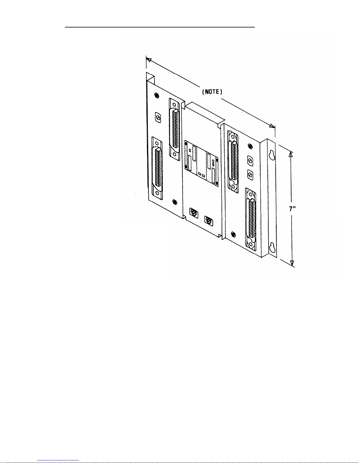
The trunk access equipment (TAE) consists of 700A-I 10-61-25 or 700A-66B1 -25 (157BF) cut-down jacks, or equivalent, and up to four 10B Emergency
Transfer Units (ETUs). The 10B ETU is shown in Figure 2-1.
700A- 110-M-25 or 700A-66-B1-25 (157BF) Cut-Down Jack
Trunk circuits that appear on the network interfaces are grouped by trunk
type (Direct Inward Dialing [DID], Central Office [CO], or Tie) and punched
down on the 700A jack. One 700A jack is required for each RJ21 X or RJ2GX
network interface. The 700A-1 10-B1-25 jack has a 110-type cut-down field,
and the 700A-66-B1-25 (157BF) has a 66-type cut-down field. It is important
to note that most secondary wiring protectors (sneak current fuses) are
compatible only with the 66-type jack.
10B Emergency Transfer Unit (ETU)
During a power failure or system outage, each 10B ETU provides contact
closures for bypassing the switch and connecting up to five predesignated
FCC registered single-line voice terminals to telephone company trunks.
Connectorized cables (25-pair) connect the ETU to the 700A jacks, the
system cabinets, and the Station Interconnect Panel. A modular plug-ended
cord (part of octopus cable) connects control power (–48 V dc) from the
system cabinet.
Screw terminals that connect to relay contacts which may be used for an
external alerting device are also provided. The relay contacts close when a
failure occurs. (Any alerting device and associated power unit with a dc
current requirement less than or equal to 0.5 ampere may be used.) The ETU
also controls a DID make-busy contact that connects to the last pair on the
700A jack. For a more detailed drawing of the 10B ETU, see Install
Emergency Transfer Units (ETUs) in this part.
2-4
Page 29
INSTALLATION
NOTE: 9“ WIDE, MOUNTING
CENTERS ARE 8-1/2”
APART, FLANGES
OVERLAPPED
Figure 2-1.
10B ETU
2-5
Page 30

INSTALLATION
Station Interconnect Panel (SIP)
The SIP is the station cross-connect field and consists of the following
equipment:
● 617A Panels
● Adapters
● 50A Fanning Strips.
617A Panel
The 617A Panel is a metal plate with keyslot holes on each side for mounting
on a backboard. (See Figure 2-2.) Each 617A Panel can hold eight 2210A2
or 858A Adapters, each of which can accommodate six connections to the
port circuits in the cabinets.
As many as five 617A Panels may be required
for a maximum size system.
The adapters snap into prepunched holes on
the 617A Panels. (Reattached spacer buttons keep adapters from touching
the metal panels.)
The cable rings located at the top of the 617A Panel route the building wiring
cables to the adapters.
Purse lock clips hold the building wiring cables in
place. The white posts at the bottom of the 617A Panel guide the wiring from
the 50A Fanning Strip to each column of adapters.
Preprinted boxes and numbers on the panel identify modular jacks for
record-keeping purposes.
Letters are marked in the boxes at the top of each
column by the installer.
The letter (A through J) and the corresponding
preprinted row number (1 through 24) identify the port jacks. For example,
Al identifies the modular jack located in column A row 1.
2-6
Page 31

INSTALLATION
MOUNTING CENTERS
WHEN FLANGES ARE
OVERLAPPED
Figure 2-2. 617A Panel
2-7
Page 32

INSTALLATION
Adapters
The adapters shown in Figure 2-3 are used at the SIP.
Z210A2 or 858A Adapters
These adapters connect the building wiring (station runs) to the station port
circuit packs (CPs) located in the system cabinets (through octopus cables).
As many as 40 of these adapters may be required for a maximum size
system, Any combination of the adapters can be used, depending upon the
type of building wiring.
The port side of the adapters consists of six 8-pin
modular jacks. The station side of the adapters is equipped as follows:
● Z210A2—Six 8-pin modular
modular plug-ended D-inside
must be installed at the top
connections for the System
Tape Unit (DTU), etc.
jacks used for terminating 4-pair
wire (DIW). One of these adapters
of column A on the SIP to provide
administration Terminal (SAT), Digital
● 858A—Six 11 O-type 8-pin wiring blocks used for terminating 4-pair
DIW.
WP90851, L1 Y-Adapter
This adapter separates voice and data pairs that are run over
cable for connection through octopus cables to the System
the same 4-pair
25 port circuits.
This adapter plugs into the port side of either of the two adapters described
above. It has a DATA and a VOICE modular jack. The DATA jack connects
to a TN726 Data Line port circuit pack. The VOICE jack connects to a port
circuit on a Tip Ring Line, Analog Line, or ATL Line circuit pack.
2-8
Page 33

INSTALLATION
Z21OA1
ADAPTER
Y-ADAPTER
WP90851,L1
858A
ADAPTER
Figure 2-3.
SIP Adapters
2-9
Page 34

INSTALLATION
Fanning Strip
The 50A Fanning Strip (Figure 2-4) is a metal panel with positions to hold 16
octopus (switch) cables. The bundled portion of the octopus cable is
anchored at the fanning strip. The eight octopus cable cords hang free. One
fanning strip is required for 1-cabinet systems. Two fanning strips are
required for 2- or 3-cabinet systems.
NOTE : 9“ WIDE, 8-1/2”
WHEN FLANGES ARE
OVERLAPPED
MOUNTING CENTERS
Figure 2-4.
50A Fanning Strip
2-10
Page 35

INSTALLATION
Cables
Splitter Cables
The splitter cables (Figure 2-5) connect trunk circuits from the 700A jacks to the
system cabinets or 10B ETU (3:1 only).
3:1 Splitter Cable (WP90929, L1)
This cable connects the twenty-four 1-pair trunk circuits on a 700A jack to three
8-port trunk circuit packs (loop start, ground start, or DID). The connection may
be either director through a
are male.
2:1 Splitter Cable (WP90929, L3)
10B ETU. Al 25-pair ribbon connectors on the cable
This cable connects eight 3-pair tie trunk circuits
trunk circuit packs. All 25-pair connectors on the
on a 700A jack to two 4-port tie
cable are male.
.
3:1 SPLITTER CABLE
WP90929,L1
2:1 SPLITTER CABLE
WP90929,L3
Figure 2-5.
Splitter Cables
Page 36

INSTALLATION
Octopus Cables
Octopus cables (Figure 2-6) connect the station port and CPU/Memory circuit
packs to the SIP adapters. Each cable consists of a 25-pair male connector that
connects to the switch cabinet and eight modular plugs that connect to the SIP
adapters. These cables are provided with all system cabinets.
Figure 2-6.
Octopus Cable
8536 Adapter Cable
The 853B Adapter Cable (104305834) connects two octopus cables to a 16-port
TN746B Analog Line circuit pack. As shown on Figure 2-6a, each cable consists
of one 25-pair male connector (Connector O) and two 25-pair female connectors
(Connectors 1 and 2). The cable length is eight feet.
CONNECTOR 1
CONNECTOR O
CONNECTOR 2
Figure 2-6a. 853B Adapter Cable
DS1
Connector Cables
The following Connector cables are available to connect the DS1 Interface circuit
packs to DS1 digital facilities:
●
H600 307, G2—50-foot long shielded cable equipped with a 50-pin male
connector on one end and unterminated at the other end. The cable
may be cut to length. Shipped loose are a KS23007, L1 15-pin male
2-12
Page 37

INSTALLATION
connector and a KS23146,L3 50-pin male connector.
To connect a DS1 interface circuit pack to a 551-type
Unit (CSU), field terminate the 15-pin plug.
To connect DS1 tie trunks on co-located System 25s,
50-pin male connector (see Figure 2-1 9).
Customer Service
field terminate the
● C6E connector cable (comcode 104307 434)—1 00-foot long shielded
cable equipped with a 50-pin male connector on one end and a 50-pin
female connector on the other end. This cable is used as an
“extension” cable between the DS1 Interface circuit pack and the other
connector cables.
Cable Labels
A set of preprinted labels for identifying the system cabinet cables and ETU
cables are provided (Figure 2-7). The system cable labels are prenumbered to
identify the cabinet (1, 2, 3) and circuit pack slot (1-12, - see NOTE) and are also
color-coded as follows:
Note: Because of the combined CP/Memory board in R2V1 and R3,
ten slots are available in Cabinet 1.
I
Cabinet No.
Color
I
1
Blue
2
Orange
3
Green
The call processor octopus cable labels and ETU cable labels are white. The
use of these labels is discussed in this manual.
2-13
Page 38

INSTALLATION
AT&T
CAR 1
CABLE
LABELS
CAB1 SLOT1
CAB1 SLOT1
CAB1 SLOT2
CAB1 SLOT2
CABl SLOT3
CAB1 SLOT3
CAB1 SLOT4
CAB1 SLOT4
CAB1 SLOT5
CAB1 SLOT5
CAB1 SLOT6
CAB1 SLOT6
CAB1 SLOT7
CAB1 SLOT7
CAB1 SLOT8
CAB1
SLOT8
CABl SLOT9
CAB1
SLOT9
CAB1 SLOT10 CAB1 SLOT10
CAB1 SLOT11 CAB1 SLOT11
CAB1 SLOT12
CAB1 SLOT12
CAB1 SLOT
CAB1 SLOT
CAB1 SLOT
CAB1
SLOT
CAB1 SLOT
CAB1 SLOT
CAB 1
BLUE
CAB 2
- ORANGE
CAB 3 - GREEN
CALL
AT&T
PROCESSOR
OCTOPUS
CABLE
LABELS
SYSTEM
SYSTEM
ADMIN ADMIN
TERM TERM
SMDR SMDR
DIGITAL DIGITAL
TAPE TAPE
UNIT UNIT
REMOTE
REMOTE
MAINT MAINT
ETU1
ETU1
SWITCH(CPU)
SWITCH(CPU)
ETU2
ETU2
SWITCH(CPU)
SWITCH(CPU)
n
WHITE
AT&T
ETU
CABLE LABELS
ETU 1 SIP
ETU 1 SIP
ETU 2 SIP ETU 2 SIP
ETU 3 SIP ETU 3 SIP
ETU 4 SIP
ETU 4 SIP
ETU SIP
ETU SIP
SWITCH(TRUNK) SWITCH(TRUNK)
SWITCH(TRUNK) SWITCH(TRUNK)
SWITCH(TRUNK) SWITCH(TRUNK)
SWITCH(TRUNK) SWITCH(TRUNK)
SWITCH(LINE) SWITCH(LINE)
SWITCH(LINE) SWITCH(LINE)
SWITCH(LINE)
SWITCH(LINE)
SWITCH(LINE)
SWITCH(LINE)
SWITCH SWITCH
SWITCH
SWITCH
ETU 1 CO
ETU 1 CO
ETU 2 CO
ETU 2 CO
ETU 3 CO
ETU 3 CO
ETU 4 CO
ETU 4 CO
ETU CO ETU CO
ETU
CO
ETU CO
Figure 2-7.
Cable Labels
2-14
Page 39

INSTALLATION
Symbols Used in Figures
Modular jacks are shown by the triangle symbol. The 25-pair connectors are
indicated by shaded blocks.
Generally, only one leg of an octopus cable is
shown. Unterminated wiring requiring cut down or other termination does not
show symbolic designations.
The 103A Connecting Block is a typical
modular wall jack that provides cut-down connections for building (station)
wiring and a modular jack for connection to terminal equipment.
2-15
Page 40

INSTALLATION
PREINSTALLATION REQUIREMENTS
The AT&T System 25 Reference Manual (555-540-200) provides a complete
listing of System 25 equipment location requirements. Before installation
begins, check the items described in this section.
Caution: System 25 cross connect hardware must be located in a
restricted access area only.
Table and Backboard
Verify that an equipment table and cross-connect backboard are installed.
(See Figure 2-8 for a sample layout.) The cross-connect backboard is a 48-
inch by 96-inch by 3/4-inch plywood panel, mounted horizontally 30-inches
above the floor and within 5 feet of the location chosen for the cabinets.
If wall space in the equipment room is limited, an alternate layout may be
provided. If more than four 617A Panels are required, this alternate layout
will require more than one 48-inch by 96-inch plywood panel. See Install
Equipment Room Station Cabling for details.
Network Interface
The RJ21X network interface (CO lines) installed by the telephone company
must be located within 25 feet of the system cabinets. In addition to the
RJ21X network interface, an RJ2GX interface is required for tie
lines. For T1
interfaces, RJ48X network interfaces must be provided.
If System 25 is
replacing another system and no additional lines are required, the network
interfaces used with the previous system should already be in place.
The network interfaces should also include a coupled bonding conductor
extended from the building service entrance.
2-16
Page 41

NOTES :
1.
2.
3.
4.
5.
115V AC, 60 Hz, 15 AMP OUTLETS
(HUBBELL 5262 OR EQUIVALENT)
MUST BE LOCATED WITHIN 4 FEET
OF SYSTEM CABINETS.
MULTIPLE CABINET SYSTEMS REQUIRE
TWO QUAD OUTLETS, SINGLE CABINET
SYSTEMS REQUIRE ONE QUAD OUTLET.
ALLOW AT LEAST 24 INCHES OF SPACE
IN FRONT OF CABINETS. TABLE MUST
BE ABLE TO SUPPORT 250 POUNDS.
BACKBOARD IS 3/4 INCHES THICK BY
48 INCHES WIDE BY 96 INCHES LONG
(FOR MAXIMUM SYSTEM).
SYSTEM 25 CABINETS AND BACKBOARD
MUST BE LOCATED IN A RESTRICTED
ACCESS AREA.
RESTRICTED
ACCESS AREA
(NOTE 5)
Figure 2-8.
Typical System 25 Floor Plan
2-17
Page 42

INSTALLATION
AC Power
All cabinets and any locally-connected System 25 peripheral equipment
(System Administration Terminal [SAT], Station Message Detail Recording
[SMDR] device, Digital Tape Unit [DTU]), and Customer Service Unit (CSU)
used for DS1 connections must be plugged into the common ac power outlet.
This outlet must have an associated ground block connected to an approved
building ground, using #6 AWG copper wire. (This ground block is the
system’s single-point ground.)
A 1-cabinet system requires one quad ac outlet. A 2- or 3-cabinet system
requires a second quad outlet and two separately fused 15-ampere circuits.
Additional ac outlets may be needed for auxiliary equipment. All ac outlets
must have the safety ground (green wire) cross-connected to the single-point
ground block on the first quad outlet. (See Figure 2-9.)
Local options may require that surge protectors be used for all peripheral
equipment used with the System 25, including the Customer Service Unit
(CSU).
Grounding
For proper grounding instructions, refer to the AT&T System 25 Electrical
Protection and Exposure Check List (555-500-1 20).
Warning:
Verify that the building ground has been provided by
one of the methods listed below, that ac power uses
approved building ground for its primary ground, and
that all voltage limiting devices are grounded to building
approved ground. Improper ground can result in
equipment failures and service outages from lightning
induced surges on the power lines.
An approved building ground for System 25 may be one of the following,
listed in decreasing order of preference:
1.
Building steel.
2. Acceptable water pipe—
a metal underground water pipe at least 1/2
inch in diameter, in direct contact with the earth for at least 10 feet.
The pipe must be electrically continuous (or made electrically
continuous by bonding around insulated joints, plastic pipe, or plastic
water meters) to the point where the protector ground is connected.
A metallic underground water pipe must be supplemented by the
2-18
Page 43

INSTALLATION
3.
4.
metal frame of the building, a concrete encased ground, or a ground
ring. If these grounds are not available, the water pipe ground can
be supplemented by one of the following types of grounds.
● Metal underground gas piping system—an electrically
continuous metal underground gas piping system that is
uninterrupted with insulating sections or joints and without
an outer nonconductive coating.
● Other local metal underground systems or structures—local
underground structures such as tanks and piping systems.
● Rod and pipe electrodes—
a 5/8-inch (solid rod) or 3/4-inch
(conduit or pipe) electrode driven to a minimum depth of 8
feet.
●
Plate electrode—expose a minimum of 2 square feet of
metallic surface to the exterior soil.
Concrete encased ground
—defined to be an electrode, consisting of
at least 20 feet of one or more steel reinforcing rods at least 1/2 inch
in diameter, or 20 feet of bare copper conductor not smaller than #4
AWG encased in 2 inches of concrete. This electrode must be
located within and near the bottom of a concrete foundation or
footing that is in direct contact with the earth.
Ground ring consisting of at least 20 feet of bare copper conductor
not smaller than
must be in direct
below the earth’s
Lightning Protection
#2 AWG encircling the building. The ground ring
contact with the earth and buried at least 2.5 feet
surface.
System 25’s lightning protection plan involves five distinct but interdependent
items required at every installation:
●
Primary protection in the form of voltage limiters (typically carbon
blocks or gas tubes) on all pairs that leave the building, whether
aerial or buried. These devices bypass surges to approved building
ground and limit potential differences between T/R pairs and building
ground to less than 1500 volts.
2-19
Page 44

INSTALLATION
● A single-point ground (SPG) system in which the green wire ground
(system ground) and the telephone company ground are connected
to approved building ground.
● The coupled bonding conductor must be connected between the
telephone company ground at the building entrance and System 25’s
SPG.
● Surge protection on the ac power to System 25.
For greater than 99 percent of all lightning strikes, the protection outlined
above will do the job.
However, there are a few locations where the
described protection may not be sufficient.
External secondary protection,
located at the trunk access area of the System 25 cross-connect field, can be
employed.
Several commercial units are available.
If 66-type block terminations are
used, a very convenient device is the LP5-230-220 Fused Lightning Protector.
This unit plugs into the 66-block (in place of the shorting bars) and includes
the sneak current fuse. One unit is required per protected pair. A ground
bar is provided with the lightning protection units or can be ordered
separately (Comcode 901-007-120). All lightning protectors located in the
System 25 cross-connect area must be grounded to System 25’s SPG via a
#6AWG copper wire.
In addition, an AC Surge Suppressor (Tll Model 428) may be required. Local
practice should be followed.
The unit plugs directly into one of the quad
outlets and provides a dual outlet to protected equipment. Sufficient units
should be provided to protect all at-powered equipment. Each cabinet in the
system requires a protected outlet, and in addition, a protected outlet is
required for each auxiliary unit, such as the SAT, a tape unit, or a printer.
When a Surge Suppressor is used, all peripheral equipment directly
connected to System 25 must be connected to alternating current via the
Surge Suppressor.
2-20
Page 45

INSTALLATION
Secondary Protection
External secondary protection,
located at the trunk access area of the
System 25 cross-connect field, is required for all trunks and off-premises
lines. Refer to Table 2-B for approved trunk protectors.
FROM AC
LOAD CENTER
(TWO SEPARATELY
FUSED 15 AMP
CIRCUITS)
SINGLE
POINT
GROUND
H
GROUND
I
LOAD
CENTER
II
(GREEN)
(#14 AWG)
I
/
TO CABINET NO. 1
GROUND BAR MOUNTED ‘ GROUND BLOCK (MAX.
ON 4“ BOX (SQUARE D
LENGTH =
20 FT.)
PK9GTA OR APPROVED
EQUIVALENT)
4“ BOX (RACO 230
OR EQUIVALENT)
HUBBELL RECPTS.
( 5262 15 AMP
OR EQUIVALENT)
4“ COVER (RACO 807
OR EQUIVALENT)
APPROVED
BUILDING GROUND
(#6 AWG, COPPER)
Figure 2-9.
AC Power Distribution—Multiple Cabinet System
2-21
Page 46

INSTALLATION
Building Wiring
Building (station) wiring (must be 24 AWG or heavier) from voice and data
terminals to the equipment location should already be in place. System 25
wiring requires that 4-pair circuits be distributed from the equipment location
to each station’s wall jack. The SIP hardware (Figures 2-2 through 2-6),
designed specifically for this purpose, is furnished with each system. Except
in extraordinary circumstances, this cross-connect hardware must be used.
In unusual circumstances where the 617A Panels are not used and some
other cross-connect equipment that does not provide a modular jack interface
to the port circuits is used, separate 4-pair circuits must be run for the voice
and data terminal at the workstation.
All examples and instructions in this
The station wiring terminations in
manual assume
the equipment
that a SIP is used.
area should have been
labeled to indicate the room location and jack number of the other end of the
line. When SIP connections are made, the connection information should be
entered on the Voice and Data Station Records Form (see Install Equipment
Room Station Cabling in this part for details).
2-22
Page 47

INSTALLATION
INSTALL SYSTEM CABINETS
Before beginning the cabinet installation, position the cabinet table within 2
feet of the ac power receptacle. Make sure that the cabinets are easily
accessible from both the front and the back.
Position Cabinet(s)
Caution: A fully-equipped cabinet weighs 80 pounds.
1.
2.
3.
4.
Check
Unscrew and remove the upper rear panel of each
unscrew the lower part with the 12 connectors.
cabinet. Do not
Near the center of the backplane, note an address plug in one of the
positions marked 1, 2, or 3 on the black address strip. (Position 4 is
not used.) This indicates the cabinet number for software purposes.
The position of the plug (1, 2, or 3) should agree with the position of
the cabinet (Cabinet 1 on the bottom, etc.).
Use the CAB 1, CAB 2, and CAB 3 labels from the cable label sheets
(Figure 2-7) to label each cabinet.
Position the cabinet label in the
box adjacent to connector 12 on the lower back panel. (The number
may have already been stamped by the factory.)
Stack the cabinets on top of one another on the stand. If there is
more than one cabinet, stack Cabinet 1 on the bottom arid Cabinet 3
on the top. Cabinet 1 contains the CPU/Memory (ZTN129 or
ZTN130 [R3]), and Service (ZTN85 or ZTN131 [R3]) circuit packs
(Figure 2-1 O). Do not replace the upper back panels yet.
Cabinet Contents
Check to make sure that the cabinets have been delivered with the correct
circuit packs (CPs). Table 2-B lists available CPs, their functions, and their
protectors.
If the system has TN760B Tie Trunk CPs, you may also have to
set the option switches on the CPs. See “Set TN760B Option Switches” in
Appendix C for details.
November 1995
2-23
Page 48

INSTALLATION
Table 2-B. Circuit Packs, Their Functions, and Protectors
Approved Secondary
Circuit Pack
Function
Wiring Protector
N/A
ZTN78
Supports single-line voice terminals.
(Must not be used on out-of-building
circuits, )
SCP-1 or 79A
TN742
Supports off-premises, out-ofbuilding, and bridged single-line
voice terminals.
lTW/LlNX343* I ROB
ZTN79
Supports the 7300H Series voice
terminals used with a MERLIN®
system. (Requires local (set) power
for distances beyond 1000 feet.)
ITWILINX343* lROB TN735
Supports MET sets.
N/A
TN726
Supports data terminals and
computers.
N/A
TN758
Contains pooled modems.
SCP-1 , SCP-2, SCP-3, ZTN76
Supports ground start trunks.
or LP5-230-220
SCP-1 , SCP-2, SCP-3,
ZTN77
Supports bop start trunks.
or LP5-230-220
SCP-1 or 79A
TN753
Supports direct inward dialing trunks.
(DID)
SCP 1 or 79A
TN760B
Supports tie trunks.
N/A
TN763
Supports auxiliary equipment.
N/A
ZTN130 (R3)
Call processing/memory.
N/A TN748B Tone Detector.
SCP-1 or 79A
TN767
Provides DS1 Interface.
N/A
ZTN131 (R3)
Provides system clocks, tone
generators, detectors, and DS1
synchronization.
SCP-1 or 79A
TN747E3
Supports ground start or loop start
trunks.
lTW/LlNX343* I ROB
TN762B
Supports hybrid voice terminals.
Must be vintage 4 or later.
*Note: lROB unit ITW341 has been replaced. Use model lTW/LlNX343 only.
2-24
November 1995
Page 49

INSTALLATION
Two fans are located on the left-hand front side of each cabinet. The
cabinet’s power supply is located behind the fans; to the right of the power
supply are up to 12 CPs in individual slots.
Each CP is identified by a label
on the front. See Figure 2-10.
1.
Remove the front cover of each cabinet.
2. Note any obviously bent or otherwise damaged circuit packs.
3. Check the CPs against the customer order. In case of irregularities
or damage, follow established notification procedures.
Danger: The System 25 cabinet contents are not user
serviceable. Some voltages inside the cabinets
are hazardous.
This equipment is to be
serviced only by qualified technicians.
The CPU/Memory (ZTN129 or ZTN130 [R3]) circuit pack has two shorting
plugs that are used for factory tests (see Figure 2-1 1). They should have
been removed at the factory.
If these shorting plugs have been accidentally
left in by the factory, the system may cold start when it should warm start.
Check the CPU/Memory CP; if the plugs are present, remove them. The
shorting plugs are located on the component side of the circuit pack.
2-25
Page 50

INSTALLATION
Figure 2-10.
Three-Cabinet System, Front View With Covers Removed
2-26
Page 51

INSTALLATION
Figure 2-11.
Position of Shorting Plugs on CPU/Memory Circuit Pack
2-27
Page 52

INSTALLATION
Required Circuit Pack Positions
The required CP positions for Cabinet 1 are:
SLOT CP
1
ZTN129 or ZTN130 (R3)
I
2
I
ZTN85 or ZTN131 (R3)
Also, all DID Trunk circuit packs should be installed in Cabinet 1.
There are no other restrictions on CP position in a single-cabinet or
multicabinet system; however, you should refer to the power supply unit load
requirements for the maximum unit loads for each CP type within a single
cabinet.
Caution:
Be careful not to exceed unit load restrictions on each
cabinet.
Label Connectors on Back Cover
Each cabinet has twelve 25-pair receptacles across the bottom of the rear
panel.
These connectors link the CPs inside the cabinet to the Station
Interconnect Panel (SIP) and Trunk Access Equipment (TAE). The connectors
are numbered from 1 to 12 and correspond to the CP slots.
Using a felt-tipped pen, write the CP code for each slot in the box above the
connector number on the lower rear cover.
2-28
Page 53

INSTALLATION
Install 4A Retainer Clips
The 4A retainer clips must be installed on each of the 12 receptacles on the
lower rear panel of the cabinets.
To install a clip, position it and insert the
legs in the cabinet as shown in Figure 2-12.
Figure 2-12.
4A Retainer Clip Installation
2-29
Page 54

INSTALLATION
Connect Cabinets
The Time Division Multiplex (TDM) bus extender cable and the intercabinet
#6 AWG ground wire must be connected between cabinets. The TDM bus
terminates on each side of the cabinet, and the intercabinet #6 AWG ground
wire connects to the ground block at the rear of each cabinet.
Note:
Make certain that the address plug is installed in the rear pin
field of each cabinet (see Figure 2-13).
TDM Bus Connections
One end of the TDM bus is terminated by resistors mounted on the ZTN129
or ZTN130 (R3) CP. This CP is always in slot 1 of Cabinet 1. The other end of
the TDM bus is terminated by a Bus Terminator that plugs into the upper pin
field of the topmost carrier (which may, of course, be the only cabinet). These
connections are shown in Figure 2-13.
Whenever a cabinet is added, the Bus Terminator must be moved to the end
of the bus on the new top cabinet.
This can be either slot 1 or slot 12,
depending on the number of cabinets and how the TDM bus extender cable
is run.
When removing a Bus Terminator and TDM bus extender cable,
to bend the backplane pins.
1.
Verify that the Bus Terminator is in the proper position:
● Slot 12 of Cabinet 1 for 1-cabinet systems
● Slot 1 of Cabinet 2 for 2-cabinet systems
● Slot 12 of Cabinet 3 for 3-cabinet systems.
take care not
2. See Note. For 2- and 3-cabinet systems, install extender cable
between slot 12 of Cabinet 1 and slot 12 of Cabinet 2. For 3-cabinet
systems, install another extender cable between slot 1 of Cabinet 2
and slot 1 of Cabinet 3.
Note:
When properly installed, the light blue stripe on the
extender cable is at the bottom of the cable and the
lettering on the cable (SER=1, for example, is right
2-30
Page 55

INSTALLATION
side up).
3.
Install the upper rear panels.
Route the extender cable between
the slots formed by the upper and lower rear panels.
2-31
Page 56

INSTALLATION
TDM
BUS
TERM
CARD
ADDR
PLUG
TDM B
EXTEN
CABLE
ADD
PLU
PLUG
Figure
~CABINET 3
ON/OFF
.SWITCH
AC POWER
# 6 AWG
BUILDING
GROUND
WIRE
CABINET 2
AC POWER
. #6 AWG
2-13.
TDM Bus Terminations (Rear View of 3-Cabinet System)
2-32
Page 57

INSTALLATION
Ground Wire Connections
The cabinets are connected to the single-point ground with #6 AWG copper
wires.
(Building ground requirements are described in Preinstallation
Requirements in this section.)
Warning:
The cabinet power switches must be set to off.
1.
In 2- or 3-cabinet systems, connect a #6 AWG wire between the
ground blocks of Cabinets 1 and 2 and Cabinets 1 and 3.
2. Connect a #6 AWG wire between the ground block of Cabinet 1 and
the single-point ground. (See Figures 2-9 and 2-1 3.)
POWER UP AND INITIALIZE SYSTEM
Separate power cords for each cabinet must be plugged into the designated
quad outlets.
Peripheral equipment (SAT, SMDR [Station Message Detail
Recording], or CAS [Call Accounting System], DTU and CSU [Customer
Service Unit]) collocated with the switch cabinet(s) must also be plugged into
these ac outlets.
Connect Power
1.
2.
3.
4.
Make sure the rear panel is in place on each cabinet.
Connect the receptacle end of a 3-wire power cord to the plug at the
rear of each cabinet.
Connect the power cord’s plug end to the quad ac outlet for each
cabinet.
Recheck the electrical and ground connections.
Danger: Once power is applied, do not put your hands or
any tools into the cabinet.
2-33
Page 58

INSTALLATION
5.
Starting with Cabinet 2 or 3, turn on the power switch on each
cabinet [Cabinet 1 must be last).
IMPORTANT: If power to Cabinet 1 is not turned
cold start initialization may not occur properly.
6.
Check to be sure that the cabinet fans are rotating.
Connect Administration Equipment
on last, the
Connect the SAT and DTU to their respective modular jacks on an 858A
Adapter at the SIP.
If the SIP has not yet been installed, connect an octopus cable to Cabinet 1,
slot 1. Make temporary connections as shown in Figure 2-14 to the SAT and
Note:
The direct octopus cable connections are only temporary.
All permanent
connections to peripheral and station
LEGEND :
ZTN129 -
cl -
355A ADAPTER -
355AF ADAPTER -
NOTE :
CPU/MEMORY CP
OCTOPUS CABLE ( WP90780 )
RS-232 PLUG TO MODULAR JACK
RS-232 RECEPTACLE TO MODULAR JACK
LEG 1 CONNECTS TO SAT; LEG 3 CONNECTS TO DTU.
Figure 2-14.
Temporary SAT and DTU Connections
2-34
Page 59

INSTALLATION
Cold Start the System
To ensure that the system recognizes the current position of the CPs, you
must cold start the system before beginning initialization. A cold start causes
the system to check all slots for valid CP types and assign default
translations to ail ports (except auxiliary trunk ports).
A limited cold start is available. The limited cold start does not assign default
translations to ports.
The limited cold start is useful if the customer’s dial
plan is significantly different from the System 25 default plan. You do not
have to delete the default codes before you enter the true dial plan. See the
Administration Manual (555-540-500) for a listing of default translations
provided in Release 3 systems.
The time required for a cold start depends on the number of CPs in the
system, but is usually several minutes.
A limited cold start takes about 30
seconds.
Follow these steps to manually start the system from the SAT:
1.
2.
3.
4.
5.
6.
Connect the SAT to the CPU/Memory CP administration port, (leg 1
of the octopus cable).
If the SAT has a selectable baud rate, set it to 1200 baud.
Be sure transmission parity is set to none, with the parity bit set to
space (0).
Turn the terminal on and press the carriage return key once or twice.
On most terminals, this key is <RETURN> or <ENTER>.
After communication with the system is established, a prompt is
displayed:
Enter Password ->
Enter SYSTEM25 and press <RETURN>. The main menu will now
be displayed along with the prompt:
Make one selection from menu ->
Enter 9 (for the SAVE/RESTORE selection) and press <RETURN>.
2-35
Page 60

INSTALLATION
7. The system will respond with:
Action=
8. Enter 20 for a cold start. The system will respond with:
Save/Restore: Action=20 Data=
9. Enter D. The system will complete the word Data followed by the =
sign.
10.
Enter 1 for a cold start or 2 for a limited cold start. The system will
respond with:
Save/Restore: Action=20 Data=1 (or
You are about to initiate a cold start
.
c to continue, any other key to abort
11. Enter c to initiate the cold start.
Data=2)
Typing errors can be erased by pressing the backspace key. Each time you
press the backspace key, one character is erased.
2-36
Page 61

INSTALLATION
Cold and warm starts both display the same type of information on the SAT. This
consists of a listing of the version of the firmware loaded in the CPU/Memory
CP, followed by a configuration listing of all CPs recognized by the system. The
CPU/Memory CP is not in the configuration listing; however, it is located in slot 1
of Cabinet 1.
Table 2-C provides a listing of SAT messages
cool or warm start. The displayed message is
and port translations.
that may be displayed during a
a result of CP occupancy, type,
Table 2-C. Displayed SAT Messages During Cold or Warm Restart
Circuit Pack (CP)
Port Translated
Displayed
in Slot
Message
No Yes
Missing
†
Yes
No
CP Type Listed #
Yes
Yes
CP Type Listed
Yes
Yes (doesn’t match
CP Type Listed*
physical CP)
Yes (Unsupported
Yes or No
Illegal
CP Type)
† Warm restart only.
# Mark indicating that the CP is unused.
* Mark indicating that the CP is mismatched.
November 1995
2-37
Page 62

INSTALLATION
The SAT message for a cold or warm start appears after the system has
performed all self-tests and reading of its configuration. Typical cold start SAT
message is as follows. The example is for a 2-cabinet system.
Typical Release 3 Version 3 Cold Start Message
RESTART
TS ROM pair
1:version 3.5 *
FC ROM pair
1:version 3.13
●
FC ROM pair
2:version 3.13’
FC ROM pair
3:version 3.13 *
COLD START
Default Password in Effect
SLOT
1
2
3
4
5
6
7
8
9
10
11
12
CABINET 1
CABINET 2 CABINET 3
ZTN85 06
TN75304
ZTN79 03
TN760B 05
ZTN79 03
TN760B 05
ZTN79 03
TN760B 05
ZTN79 03
TN760B 05
ZTN78 02
ZTN78 02
ZTN78 02
TN74703
TN74703
TN748 06
* This is important information that should be noted in trouble reports.
Message: Type <RETURN> for prompt.
Enter <RETURN>. The system will respond with the administration prompt:
SYSTEM 25 ADMINISTRATION
(CPU/Memory release information)
AT&T Copyright 1988
Enter password -->
2-38
November 1995
Page 63

INSTALLATION
Check Performance of Cabinet Components
Each CP has three colored LEDs on the front panel that indicate whether it is
functioning properly or not.
When a cold start is performed, the system
undergoes a series of self-tests and loads default translations.
Upon initial power application, each CP tests itself. The red LED on the CP
lights to indicate that the test is in progress. Once the CP passes its initial
tests, the red LED goes off. Then, after the main processor recognizes the
CP and can communicate with it, the green LED lights. When all green LEDs
are lighted, the testing and loading process is complete. This process takes
about 3 minutes.
1.
Make sure that both fans in each cabinet are on and operating.
2. Make sure that the green LED on the power unit behind the fan
assembly is lighted.
3. Check the CP LEDs. Table 2-D lists the LED status of each type of
CP.
2-39
Page 64

INSTALLATION
Table 2-D.
Circuit Pack LED Status Indications
Circuit Pack Type
LEDs if Normal
LEDs if Failed
Service Circuit (ZTN85 Steady Green and
Steady Red or
or ZTN131 [R3])
Flashing or Amber Off
Steady Amber
CPU/Memory (ZTN129 Flashing Green Steady Green
or ZTN130 [R3])
or Off
All Other Steady Green Steady Red
(Amber Also lighted
(see Note below)
when CP in use)
Note:
The red and green LEDs can both be lighted at the same
time. In normal operation, a lighted red LED indicates that
an alarm has been recorded for that CP. If the green LED is
also lighted, the main processor can communicate with the
CP. A lighted amber LED indicates that a resource on the
CP is being used.
A lighted red LED and a dark green LED
indicates that the CP diagnosed itself to be so bad that it has
removed itself from the system.
2-40
Page 65

INSTALLATION
If all the CPs are operating properly, only the green LED on the CPU/Memory CP
and the amber LED on the Service Circuit should be flashing. If any other CP
has a no-lighted LED, the CP may need to be reseated. All port CPs green LED
remains dark until at least one port on the CP has been translated.
Except for the CPU/Memory CP and Service Circuit CPs, power can be left on
while a CP is reseated. To reseat a CP, do the following:
1.
2.
3.
4.
5.
6.
7.
See CAUTION. Make sure your hands are clean and dry. Put on a wrist
grounding strap, and clip it to the grounding block at the rear of the
cabinet.
Caution: Static electricity can damage a CP.
With your thumb, pull up on the latch pin of the removal lever. (See
Figure 2-15.)
When the latch pin is up, pull the removal lever down until it stops, at an
angle of about 30 degrees to the floor.
Tugging hard, pull the CP out a few inches. Leave it out for at least 30
seconds, and then push it back firmly into its slot. When it is almost back
in place, you’ll feel resistance. The removal lever will start to return to its
vertical position.
Push the lever all the way to vertical until it catches on the latch pin.
After the power-up, repeat this process for each CP with dark LEDs
(except for ZTN129 orZTN130 [R3] and TN763s).
Recheck the LEDs on all CPs. (If a CP’s LEDs are not lighted, the CPs
are considered “unadministered” by the CPU. ) A lighted red LED on any
CP indicated that it is faulty.
November 1995
2-41
Page 66

INSTALLATION
Figure 2-15.
Typical System 25 Port Circuit Pack
Report Problems
Follow local procedures to report faulty or damaged equipment.
2-42
November 1995
Page 67

INSTALLATION
Initialize System
Instructions
for initializing the system
(based on the completed
implementation
forms) are provided in the Administration Manual
(555-540-500).
Note:
Before trunks using DS1 Signaling are administered, all link
level parameters such as signaling and framing and all link
level alarms must be cleared. If this is not possible, PBXs at
each end will not work.
If this condition exists, clear a
maintenance busy condition that exists at each end.
INSTALL CROSS-CONNECT EQUIPMENT
Before starting, familiarize yourself with the following equipment described in
CROSS-CONNECT EQUIPMENT DESCRIPTION:
● Trunk Access Equipment (TAE)
● Station
700 A-110-B1 -25 or 700A-66-B1-25 Wiring Jacks
10B Emergency Transfer Units
Interconnect Panel (SIP)
617A Panels
858A or Z210A2 Adapters
50A Fanning Strips.
Figure 2-16 shows a typical SIP and TAE backboard layout. Figure 2-17
shows an alternate layout that can be used when horizontal wall space is
limited. These layouts can be reversed when the switch cabinet(s) must be
installed to the right of the backboard.
2-43
Page 68

INSTALLATION
Install TAE, 617A Panels, and Fanning Strips
To install this equipment, proceed as follows:
1.
2.
3.
4.
5.
6.
7.
8.
9.
10.
11.
For each RJ21X, RJ2GX, and RJ48X
700A Jack 1/2-inch from the edge of
switch cabinet(s).
Mount the first 617A Panel.
network interface, install one
the backboard closest to the
Position and mount the first 50A Fanning Strip next to the 617A
Panel. The edges should overlap so that the same screws will go
through the overlapping key slots in the 50A Fanning Strip and the
617A Panel. The bottoms of the fanning strip and panel are flush.
If required, mount a second 50A Fanning Strip above the first.
Mount the first 10B Emergency Transfer Unit (ETU) in the position
shown in Figure 2-16 or Figure 2-17. Overlap the edges of the ETU
and the panel so that the same screws will go through the
overlapped key slots.
Mount the remaining 617A Panels. Overlap the panels to conserve
space and to reduce the number of screws required; however, do
not mount more than three panels on either side of the 50A Fanning
Strip.
If required, install the second ETU above the first.
If additional ETUs are required, install them close to the 700A Jacks
(Figure 2-1 6). If the alternate SIP arrangement (Figure
install additional ETUs above the second ETU.
Using a felt-tipped pen, letter the adapter columns (A
the 617A Panels, starting with the left side. For
arrangement, start with the left side on the lower row.
Using a #12 AWG ground wire, connect the ground
2-17) is used,
through J) on
the alternate
points on the
ETUs (screw terminal on the upper left side) and link them to the
single-point ground.
Install D rings as required below the 700A Jacks and 617A Panels.
2-44
Page 69

INSTALLATION
FIRST
108 ETU
PLYWOOD
BACKBOARD
1/2"
ADD'L 700A
BLOCK
ADD'L
ETU
ADD'L 700A
BLOCK
ADD'L 700A
BLOCK
ADD'L
617A
PANEL
ADD'L
617A
PANEL
ADD'L
617A
PANEL
ADD'L
617A
PANEL
ADD'L 700A
BLOCK
ADD'L
ETU
700A
BLOCK
ADD'L
ETU
700A
BLOCK
TO SWITCH
CABINET
D-RINGS AS REQ'D
FIRST
617A
PANEL
FIRST 50A
FANNING
STRIP
FLOOR
FREE HANGING OCTOPUS
CABLE WITH 65" FREE LENGTH
Figure 2-16.
SIP and TAE Backboard Layout
2-45
Page 70

INSTALLATION
NOTE: GREATER
THAN 48" FOR
5-PANEL
ARRANGEMENT
FIRST
108
ETU
Figure 2-17. Alternate SIP and TAE Backboard Layout
2-46
Page 71

INSTALLATION
Mount 858A or 2210A2 Adapters
To install these adapters, proceed as follows:
1. Using a wide blade screwdriver, pry off the upper adapter mounting
clip on the 617A Panel (Figure 2-18).
2.
Fit the mounting clip on the top of the adapter.
3. Fit the adapter in the slot of the lower mounting clip.
4.
Press the upper mounting clip back into the panel.
2-47
Page 72

INSTALLATION
UPPER ADAPTER
MOUNTING
CLIP
Figure 2-18.
Mounting Adapters
Page 73

INSTALLATION
INSTALL MODULAR BULK POWER SUPPLY
(Optimal)
The 346 Modular Bulk Power Supply (MBPS) is a cost-effective and flexible
alternative to the KS-2291 1 power supply. The 346 MBPS can be used
where the wall-mounted (outlet) KS-2291 1 power supply cannot be used or
where multiple KS-2291 1 power supplies are required.
The 346 MBPS consists of the 346A Power Unit and 346A1 Power Panel. Up
to three 346A Power Units can be mounted in a power panel. Each 346A
Power Unit is capable of powering four terminals with adjuncts (“1 O w“
position), for a total of 12 terminals.
Terminals powered by the 346A Power
Unit can be located up to 1000 feet from the unit.
The 346 MBPS should be installed near the SIP. Service to the ac outlet
powering the 346 MBPS must be a dedicated (nonswitched) 20-ampere line.
A maximum of four power panels can be connected to the 20-ampere line.
The AC Surge Suppressor (T11 Model 428) should be used with the 346A1
Power Panel.
INSTALL EQUIPMENT ROOM TRUNK CABLING
As mentioned earlier, all outside lines must be connected to the system
through connectorized network interfaces. These interfaces are connected to
wall-mounted trunk access equipment (TAE), and from there to the cabinets.
Connect Network Interfaces to TAE Blocks
The trunks and off-premises stations from the network interface must be cut
down on the TAE’s connecting blocks so that the trunks are grouped by type
(loop start, ground start, DID, and tie) at the connecting block. Each
connecting block can handle up to three groups of eight trunks or two groups
of four tie trunks.
Each group can contain only one type of trunk. For loop start, ground start,
and DID trunks, the first group of eight trunks goes to leg 1 of the splitter
cable; the second group of eight trunks goes to leg 2; and the third group of
eight trunks goes to leg 3. For tie trunks, the first group of four trunks goes
to leg 1 of the splitter cable; and the second group of four trunks goes to leg
2.
2-49
Page 74

INSTALLATION
Tie trunks must be segregated on a separate block because a different
splitter cable is used. Also, off-premises stations must be segregated one
700A Jack.
The first five trunks in each group of eight (loop start or ground start trunks
only) can be connected through an ETU to five power failure transfer stations.
However, all eight trunks are connected to, and pass through, the ETU.
The ETU also supports a DID make-busy function to the central office’s extra
pair (if required). Relay contacts for the DID make-busy function appear on
the 25th pair on the TAE block. The relay contacts are normally open. When
power fails, the contacts close, making all DID trunks appear busy to the
central office. This prevents the central office from taking the DID trunks out
of service.
A maximum of four ETUs are supported.
For a system with more than one
ETU, apportion the emergency transfer trunks so that they are in the first
subgroup of five in each subgroup of eight trunks on a connecting block.
1.
Connect an A25D 25-pair single-ended cable to each network
interface receptacle.
2. Cut down the other end of each cable on the top terminal row of a
700A Jack in groups of eight trunks (four for tie trunks), as described
above (see Note). Cut down the DID make-busy pair (if provided) to
terminals 49 and 50 on the block.
Note:
Facilities used for off-premises stations, must be
segregated on one 700A Jack.
3.
Install secondary wiring protectors (sneak current fuses) between the
bottom terminal rows on the 700A Jacks for each trunk cut down on
the top row. (Approved protectors are listed in Table 2-B, along with
their respective CPs.)
2-50
Page 75

INSTALLATION
Connect Cabinets to TAE Blocks
The connections between the cabinets and the TAE blocks are made using
connectorized splitter cables. Make sure that each trunk group on each
connecting block is connected to the correct type of CP and protected with
its approved secondary protector
(as shown in Table
2-B).
Central office trunks associated with emergency transfer and off-premises
stations (OPSs) are not connected directly to the cabinets.
If you are
installing trunks that are to be used for OPS, see Off-Premises
Stations
in this
part.
Also, to complete the procedure for installing trunks used for
emergency transfer, you must go to
Install Emergency Transfer Units (ETUS)
in this part.
Connect Ground Start, Loop Start, and DID Trunks
A 3:1 connectorized splitter cable, WP90929, L1, is required to connect the
700A Jack to the cabinet for these trunks.
1.
2.
3.
4.
5.
6.
Install secondary protectors (see Table 2-B).
Using the cable label sheets provided (Figure 2-7), label the back of
the hood of each of the connectors (1, 2, and 3) on the three legs of
the splitter cable (see Note). Use an appropriate cabinet and slot
number label (CAB 1 SLOT9, for example).
Note: If one or more of the legs contain trunks that are to
be used for emergency transfer, do not label these
legs. Set the legs aside and go to
Install Emergency
Transfer Units (HUS)
in this part to complete the
installation of these trunks.
On connector O, install labels that correspond to those used on each
of the three splitter cable legs.
Position the labels so that they will
be clearly visible after the cable is plugged in.
Plug connector O into the 700A Jack.
Except for legs containing trunks to be used for emergency transfer,
connect connectors 1, 2, and 3 to the cabinet.
Connect only to
ZTN76 Ground Start, ZTN77 Loop Start, or TN753 DID CPs.
Repeat procedure as required.
2-51
Page 76

INSTALLATION
Connect Tie Trunks
A 2:1 connectorized splitter cable, WP90929, L3, is required to connect the
700A Jack to the cabinet for tie trunks.
1.
2.
3.
4.
5.
6.
Install secondary protectors (see Table 2-B).
Using the cable label sheets provided (Figure 2-7), label the back of
the hood of each of the connectors (1 and 2) on the two legs of the
splitter cable.
Use an appropriate cabinet and slot number label
(CAB 1 SLOT8, for example).
On connector O, install labels that correspond to those used on each
of the two splitter cable legs. Position the labels so that they will be
clearly visible after the cable is plugged in.
Plug connector 0 into the 700A Jack.
Plug connectors 1
Tie Trunk CP.
Repeat procedure
and 2 into the
as required.
cabinet. Connect only to a TN760B
2-52
Page 77

INSTALLATION
Install
DS1
DS1 signaling allows a digital connection between the System 25 and other
PBXs, Central Offices, Toll Offices, off premise stations, and data end points
such as host computers. The TN767 emulates ground start, Ioopstart, tie and
DID Trunks in addition to off premises stations. The ZTN131 circuit pack
provides the required digital synchronization.
The TN748 circuit pack will provide
the Touch Tone registers.
The term synchronization refers to an arrangement where by digital facilities
operate from a common clock.
This allows the receiving facilities to keep the
digital signals in step or synchronized.
Synchronization can be provided by the
system 25 any other PBX it is connected to, or by the CO being used by the
network, Synchronization must be properly engineered before installation is
begun. Each node must be aware of the synchronization plan so that it may be
properly administered.
The TN767 circuit pack generates a signal that is shaped in a manner that when
it reaches the cable it conforms to power specifications. The level of the signal
must be adjusted according to the cable distance. If the DS1 Interface
terminates at the cross connect field or at a CSU, the total cabling distance must
be used. If the DS1 Interface terminates on another PBX (direct connection), a
phantom point midway between the two PBXs should be used as the reference
point. The line equalization/compensation for S25 is set via administration
procedures from the SAT.
Connect S25 to Another On Premises PBX
When the S25 and the other PBX are in the same building, the cabling is broken
down into three different distance ranges. The first connection is for distances of
1310 feet or less. The second distance range is 1311 to 4310 feet which
requires the use of a Customer Service Unit (CSU) equipped with an Office
Repeater. The third distance range is greater than 4311 feet. It uses a CSU and
T1 line repeaters as required.
Direct Connection—Less Than 1310 Feet
Figures 2-19 and 2-20 show two different direct connections. Figure 2-19 is
normally used for connecting a S25 to another PBX that is virtually side by side.
Figure 2-20 is used for direct connections that involve more distance. Figure
2-20 shows two S25s but a DEFINITY G1 or G2, System 75, or System 85 can
be connected directly to the S25. Consult the System 85 installation manual
(555-103-104) or the DEFINITY G1 Wiring Guide (555-204-111) or the System
75 Wiring Guide (555-200-111) for the connection information for those PBXs.
2-53
Page 78

INSTALLATION
Figure 2-19.
Direct Connection (Side by Side)
NOTE: FOR DISTANCES OVER 50 FEET (15.2 M)
USE C6E CONNECTOR CABLE(S) BETWEEN
H600 307,G2 CONNECTOR CABLE AND DS1
TRUNK CIRCUIT PACK.
Figure 2-20.
Direction Connection (Side by Side)
Connections Between 1311 and 4310 Feet
For distances between 1311 and 4310 feet, CSUs equipped with Office repeaters
must be used to regenerate the DS1 signal. See “Install CSU” section of this
manual for the installation instructions for the CSU. Figure 2-21 shows a
functional diagram of this connection.
If the connection is being made between
the S25 and a DEFINITY G1 or G2, System 75, or System 85, refer to the
System 85 Installation Manual (555-1 03-104) or the DEFINITY G1 Wiring Guide
(555-201-1 11) or the System 75 Wiring Guide (555-200-111) for the connecting
information.
2-54
Page 79

Figure 2-21. DS1 Connections—1311 to 4310 Feet
DS1 Connections—4311 Feet or More
For distances of more than 4311 feet, T1 line repeaters are required in
addition to the CSUs. See the “Install CSU” section of this manual for
installing the CSU.
Figure 2-22 shows
a functional diagram of this
connection. If the connection is being made between the S25 and a DEFINITY
G1 or G2, System 75, or System 85, refer to the System 85 Installation
Manual (555-1 03-1 04) or the DEFINITY G1 Wiring Guide (555-204-111) or the
System 75 Wiring Guide (555-200-111) for the connecting information.
CSU
(NOTE)
PROTECTION
CIRCUIT
655 FEET
MAXIMUM
DS1 LINE
WITH
REPEATERS
DSX-1*
CSU
DS1
(NOTE)
PROTECTION
CIRCUIT
655 FEET
MAXIMUM
NOTE : USE OF THE OFFICE REPEATER IS OPTIONAL DEPENDING
UPON THE DISTANCE TO THE FIRST T 1 REPEATER
*DSX-1 REFERS TO A PHYSICAL CROSS-CONNECT FOR DS1
SIGNALS
Figure 2-22. DS1 connections—4311 Feet or More
2-55
Page 80

INSTALLATION
Off Premises Metallic (Cable) Connections
The connection between the System 25 and another DS1 interface is in most
cases a T1 line with repeaters. The proper lightning protection must be
provided (as shown in Table 2-B). Figure 2-23 shows a diagram of the off
premise cabling.
See the “install CSU” section of this manual for the
installation instructions for the CSU.
*DSX-1 REFERS TO A PHYSICAL CROSS-CONNECT FOR DS1 SIGNALS
Figure 2-23.
DS1 Connections—Off Premise Cabling
Off Premises Non Metallic Connections
Many alternatives to DS1 metallic transmission facilities exist. Some of these
systems include Iightguide (fiber optics), microwave, infrared, and radio
waves. Other type transmission facilities can be used as long as they are
technically compatible and connected via the DS1 cross connect point.
Figure 2-24 shows a block diagram of non metallic cabling transmission
systems.
2-56
Page 81

INSTALLATION
MICROWAVE
INTERFACE
MICROWAVE
INTERFACE
LIGHT-GUIDE
INTERFACE
LIGHT-GUIDE
INTERFACE
INFRARED
INTERFACE
INFRARED
INTERFACE
655 FEET
MAXIMUM
ANY DS1
INTERFACE
655 FEET
MAXIMUMANY DS1
INTERFACE
Install
*DSX-1 REFERS
Figure 2-24.
DS1
Customer Service
TO A PHYSICAL CROSS-CONNECT FOR DS1 SIGNALS
Connections—Non Metallic Connections
Unit (CSU)
The CSU may either be rack mounted or mounted as a standalone unit. It
can be equipped with several different plug in units, the Signal Monitor Unit,
T1 Office Repeater, and a Fault Location Filter.
Install the Plug In Units
Refer to the documentation provided with the CSU for the information for
setting the options and installing the plug in units.
Mount the CSU
The CSU may either be rackmounted or mounted as a standalone unit. If the
CSU is to be rack mounted, insert the unit and attach it to the cabinet
uprights using four screws.
If the unit is a standalone unit, place it in the
designated location.
The CSU should be mounted as close to the network
interface as possible.
2-57
Page 82

INSTALLATION
Connect the CSU
The CSU can be powered by the line or from a locally provided -48 V dc
power supply. Figure 2-25 shows the connections for connecting the CSU.
The 48 V and GRD leads are optional according to how the CSU is powered.
H600 307 ,02
CONNECTOR
CABLE (NOTE)
NOTE : FOR DISTANCES OVER 50 FEET ( 15.2 M)
USE C6E CONNECTOR CABLE(S) BETWEEN
H600 307,02 CONNECTOR CABLE AND DS1
TRUNK CIRCUIT PACK .
TO LOCALLY
PROVIDED -48V
POWER SUPPLY
Figure 2-25. CSU Connections
Line Compensation/Equalization
Determine the cable distance of the line, either to the line termination or
“phantom” midpoint of a direct connection.
Refer to the System 25
Administration Manual (555-540-650) for instructions on setting the line
equalization.
Connect Coupled Bonding Conductor (CBC)
Each network interface (RJ48X) is associated with a service entrance
(protector block) ground. A CBC should be connected to this ground. If the
local telephone company has not run a CBC up to the network interface, you
should run it yourself. Use #12, #14, or #16 AWG wire. Start the CBC at
the protector block ground, and run it as close as possible to the facilities
cable. If possible, tie wrap the CBC to the facilities cable. Do not use spare
pairs in the telephone company cable for this purpose.
2-58
Page 83

INSTALLATION
Consideration should be given to installing secondary protection on each
out-of-building facility connected to the TAE if any of the following conditions
exist:
● The service entrance (protector block) ground is not properly
installed (bonded to building ground, for example).
● The local telephone company does not permit access to the
protector block.
●
High-voltage surge protection is not provided.
Install the CBC as follows:
1.
Connect one end of the CBC to the ground point at the network
interface.
2. Wrap the CBC loosely around the cable from the network interface
to the TAE and then around a splitter cable to the cabinet. If
possible, tie wrap the CBC to the cables.
3. Connect the end of the CBC to the ground block on Cabinet 1. See
Figure 2-13.
2-59
Page 84

INSTALLATION
INSTALL EQUIPMENT ROOM STATION CABLING
System 25 is connected to the building (station) wiring in two stages. First,
the building wiring is connected to the Station Interconnect Panel (SIP).
Then, the octopus cables from the back of the cabinets are connected to the
SIP.
Accurate documentation during installation is essential to the performance
and maintenance of System 25 and will make initialization and administration
much easier to perform.
The Voice and Data Station Records Form (Figure
2-26) traces the connection from the workstation where the voice or data
terminal is located to the SIP. Obtain this form from the Implementation
forms that the TC or TCSS has prepared for system initialization. When you
install the station wiring, enter the jack number and SIP number for each
terminal to identify each end of the cable run. Number and label the station
jacks per local practice.
As the octopus cables
each station should be
are connected to the SIP, the port assignment for
added to the Voice and Data Station Records Form.
Port assignments are identified by cabinet number (1, 2, or 3), circuit pack
slot number (1 through 12), and port number (1 through 8). For example
1-10-06 or 11006 identifies port number 6 in the circuit pack located in slot
number 10 of Cabinet 1. The port number is the same as the octopus cable
leg number.
2-60
Page 85

INSTALLATION
.
2-61
Page 86

INSTALLATION
Connect Building Wiring to SIP
The type of building wiring termination determines what types of adapters are
used. Two types are supported: 4-pair cable (cut down) and modular jack.
Any combination of adapters may be mounted on a 617A Panel. Cluster the
connection on the SIP by voice terminal type: single-line, 7300H Series*,
Multibutton Electronic Telephone (MET), and voice/data.
Modular Plug Termination
Each 4-pair modular plug supports one station (Figure 2-27). It connects to a
modular jack in a Z210A2 Adapter.
1.
2.
3.
4.
5.
6.
7.
Run the 4-pair cable through the rings at the top of the 617A Panels.
Connect the plug to any Z210A2 Adapter.
Feed the cable into the two purse lock clips at the adapter.
Using a felt-tipped pen, record the building wiring destination on the
adapter’s grey modular jack.
Repeat the process until all of the 4-pair building cables are
connected to the SIP. Some spare adapters should be left on the SIP
to accommodate growth.
Twist the purse lock clips closed.
Document the connections you have made on the Voice and Data
Station Records Form (Figure 2-26).
●
These terminals are also used in a MERLIN communications system.
2-62
Page 87

INSTALLATION
Z21OA1
ADAPTER
(MODULAR TO
MODULAR)
PURSE
LOCK CLIP
/
( TYPICAL)
Figure 2-27.
Modular Plug Terminations Connected to the SIP
2-63
Page 88

INSTALLATION
4-Pair Cable Terminations
Each 4-pair cable supports one station (Figure 2-28). It connects to a wiring
block on a 858A Adapter.
1.
2.
3.
4.
5.
6.
Run the 4-pair cable through the rings at the top of the 617A Panels.
Cut down the leads starting with Pin 1 of the wiring block located
beside the modular jack (Figure 2-28).
Wiring Block
DIW Cable
Pin No.
Color Code
1
W-BL
2
BL-W
3
W-O
4
O-W
5
W-G
6
G-W
7
W-BR
8
BR-W
Using a felt-tipped pen, record the building wiring destination on the
wiring block caps.
Repeat the process until all of the 4-pair building cables are
connected to the SIP. Some spare adapters should be left on the
SIP to accommodate growth.
Feed the six cables for each adapter into the two purse lock clips at
the adapter. Twist the clips closed.
Document the connections you have made on the Voice and Data
Station Records Form (Figure 2-26).
2-64
Page 89

INSTALLATION
ZZ1OA1
ADAPTER
(MODULAR TO
MODULAR)
PURSE
LOCK CLIP
(TYPICAL)
Figure 2-28.
Cut Down Terminations Connected to the SIP
2-65
Page 90

INSTALLATION
Connect Cabinets to SIP
Table 2-E shows the type of terminals that can be connected to each CP type
and the maximum allowable cabling distances to the system cabinets. Refer to
the Voice and Data Station Records Form for the terminal types assigned to each
workstation.
Caution:
Connecting a terminal to the wrong type of CP can
damage the pack.
Table 2-E.
Circuit Pack Versus Terminal Type
Circuit Pack Terminal Type
Distance (in feet) From Cabinets
Using 24 AWG Wire
ZTN79
7300H Series and ATL 2,000 (See Note 1 )
TN762 Cordless Telephone
TN735
MET (4 Ports)
1,000 (in-Building Only)
ZTN78
Single-Line 2,000 (in-Building Only,
Non-Bridged)
TN742
Single-Line
24,000 (or Class COPS)
TN746B
(Out-of-Building,
extended, or
off-premises)
(Note 2)
TN726
Data Terminals and
2,000 (in-BuiIding Only,
Computers
(Note 3)
TN767
I
Single-Line Off
655 (Note 4)
Premises
Note 1:
/Vote 2:
Note 3:
Note 4:
Local (set) power is required for distances beyond
1,000 feet.
Only five sets can be bridged, and only two can be
off-hook at the same time.
This distance is for 19.2 Kbps data rate. At lower
speeds, the distance is greater. Also, this distance
can be limited by the terminal type. See the
Reference Manual(555-540-200) for details.
DS1 signaling for off-premises station. The
distance from the cabinet to the CSU is 655 feet.
2-66
Page 91

NSTALLATION
Prepare Carrier Loading Labels
As you connect the port CPs in each cabinet to the SIP, list the connections
on the Carrier Loading label. This label is mounted on the inside of the front
cover of the cabinet. (See Figure 2-29.) Keep track of –48 volt power usage
so that the power supply is not overloaded.
1.
2.
3.
4.
Enter, the CP type under the appropriate slot number.
For each port, enter the terminal type and the unit load, referring to
the Unit Load by Station Set Type label attached near the Carrier
Loading label. (This information is also contained in Appendix C of
this manual.) No port can have a unit load greater than 2.
When you have made entries for all- the ports of a CP, calculate the
total unit load for that CP and enter the calculation in the
appropriately marked square.
When you have made and documented all the connections for a
cabinet, check the total unit load to make sure that it does not
exceed the maximum of 80. (See Appendix C for more information
on evaluating unit load.)
2-67
Page 92

INSTALLATION
2-68
Page 93

INSTALLATION
Modify Octopus Cables if Required
If flag--type cable ties are shipped loose, they must be installed on the early
production octopus cables. The flag-type cable tie location depends on the
type of SIP arrangement (Figures 2-16 and 2-17). Also, if the alternate SIP
arrangement is used, later production octopus cables must be modified.
1.
Check the octopus cables, if they have flag-type cable ties, go to
Step 3. Otherwise, go to step 2.
2. Install flag-type cable tie so that the eight free ends of the octopus
cable are 65 inches long for the standard SIP arrangement or 77
inches long for the alternate SIP arrangement.
3. If the alternate SIP arrangement (Figure 2-17) is used, clip off the last
flag-type cable tie so that the eight free ends of the octopus cable
are 77 inches long (Figure 2-30).
2-69
Page 94

INSTALLATION
TO SWITCH
TO SWITCH
DISTRIBUTION RING
FLATTEN OCTOPUS CABLE
BEFORE FEEDING
INTO THE
50A FANNING STRIP
ION THE FLAG
MOD PLUG ENDS TO
FAN OUT TO
(D-RINGS) AS REQ’D
ADAPTERS ON SIP
TIE WRAP IN FRONT
OF THE WIRE FORM
SIP
FLAG TIE WRAP
WITH OCTOPUS CABLE
IDENTIFICATION LABEL
Figure 2-30.
Standard and Modified Octopus Cables
2-70
Page 95

INSTALLATION
Make SIP Connection for CPU/Memory
In all cases, the CPU/Memory is connected to the SIP via an octopus cable.
Since there are four ports on the CPU/Memory (port 1 for the SAT, port 2 for
SMDR, port 3 for the DTU, and port 4 [reserved]), plugs 1 through 3 on the
octopus cable are used to connect the peripheral equipment. (Plugs 7 and 8
connect to the ETU; plugs 4, 5, and 6 are not used.) Plugs 1, 2, 3, 7, and 8
plug into a designated adapter on the SIP.
1.
2.
.
3.
4.
5.
6.
7.
Before installing the octopus cable for the CPU/Memory CP, label
the 25-pair connector and flag-type tie wrap with a CAB 1 SLOT1
label from the cable label sheets (Figure 2-7). Position the label on
the back of the hood of the 25-pair connector.
Label the octopus cable legs, close to the modular plugs, as follows:
Leg
Label
1
SYSTEM ADMIN. TERM
2
SMDR
3
DIGITAL TAPE UNIT
7
ETU 1 SWITCH (CPU)
8
ETU 2 SWITCH (CPU)
Connect the cable to Cabinet 1, slot 1, and run the cable horizontally
through the D-rings to the 50A Fanning Strip.
Mount the cable in the fanning strip (Figure 2-31).
Insert the octopus modular plugs into the Z210A2 Adapter jacks on
the SIP per the Voice and Data Station Records Form (Figure 2-26).
If an ETU is provided, connect modular plug 7 to
on the ETU.
If a second ETU is provided, connect modular
(cpu) jack on second ETU.
SWITCH (cpu) jack
plug 8 to SWITCH
2-71
Page 96

INSTALLATION
FLAG-TYPE
CABLE TIES
STANDARD CABLE
I
MODIFIED CABLE FOR
(FLAG TIE
ALTERNATE SIP ARRANGEMENT
AT 65” REMOVED)
Figure 2-31.
Mounting Octopus Cable on Fanning Strip
2-72
Page 97

INSTALLATION
Make SIP Connections to Cabinet for 7300H Series Terminals
1.
2.
3.
4.
5.
6.
7.
8.
9.
Select the cable label sheet (Figure 2-7) that identifies the cabinet
(blue for #1, orange for #2, and green for #3).
On an octopus cable, attach an appropriate label (CAB1 SLOT8, for
example) on the last flag-type cable tie and on the back of the hood
of the 25-pair connector.
Connect the 25-pair connector end of the octopus cable to an
appropriate receptacle (ZTN79) on the switch cabinet.
Run the octopus cable horizontally through the D-rings and mount it
on the 50A Fanning Strip as shown in Figure 2-31.
Repeat the previous steps for each ZTN79 receptacle, so that all
octopus cables linking 7300H Series terminals to the cabinet are
labeled and run to the 50A Fanning Strip.
Check the Voice and Data Station Records Form to see which SIP
adapter jacks are connected to 7300H Series terminals.
Connect port 1 of the first ZTN79 to the primary attendant console.
Connect port 2 of the same CP to the primary attendant’s Direct
Extension Selector (DXS) console (if present).
Connect the remaining plugs on the octopus cable to other 7300H
Series terminal SIP jacks. Connect other ZTN79 CPs to other 7300H
Series terminal adapters. Distribute the 34-button Deluxe and BIS
terminals equally among all ZTN79 circuit packs.
Fill in the port ID of each station on the Voice and Data Station
Records Form (Figure 2-26).
November 1995
2-73
Page 98

INSTALLATION
Make
SIP
Connections to Cabinet for MET Sets
Follow the same procedure as for 7300H Series terminals to connect MET set
SIP appearances to the appropriate CPs as outlined below:
●
●
●
●
●
Note:
Connect the 25-pair connector to a TN735 CP
Attach a cable label to the octopus cable 25-pair connector and flag-
type tie wrap
Run the cable 10 the 50A Fanning Strip
Plug cable ends into the appropriate SIP adapters
Complete the Voice and Data Station Records Form.
Each TN735 CP supports only four MET sets. Therefore, only the first
four modular plugs on each octopus cable should be connected to the
SIP adapters.
Make SIP Connections to Cabinet for Single-Line Sets
Follow the same procedure as for 7300H Series terminals to conned single-line
voice terminal SIP appearances to the appropriate CPs as outlined below:
●
Connect the 25-pair connector of the octopus cable to a ZTN78 CP
●
Attach a cable label to the octopus cable 25-pair connector and flagtype
tie wrap
●
Run the cable to the 50A Fanning Strip
●
Plug the cable ends into the appropriate
Voice and Data Station Records Form.
For extended, off-premises, and out of-building
adapters, and complete the
stations, follow the same
procedure as above, except connect the octopus cable to a TN742/TN746 CP.
For Connection to a TN746 CP, follow the procedure outlined below.
●
Attach the connector marked “0’ of the 853B adapter to a TN746 CP
("0")
2-74
November 1995
Page 99

INSTALLATION
●
Attach cable labels to the two octopus cable 25-pair connectors and
flag-type tie wrap.
●
Attach octopus cables to the 853B adapter
●
Run the cables to the 50A Fanning Strip.
●
Plug the cable ends into the appropriate adapters, and complete the
Voice and Data Station Records Form.
November 1995
2-74a
Page 100

INSTALLATION
Make SIP Connections for Data Terminals and Computers
Any RS-232C compatible data terminal, personal computer host computer, or
a STAR LAN NETWORK workstation can be connected in one of four ways:
●
If the terminal has a modem, it should be connected to a ZTN78 CP
in the same way as a single-line voice terminal.
● The terminal’s RS-232C port may be connected to an Asynchronous
Data Unit (ADU) and then to the SIP over standard building wiring.
Use an octopus cable to connect the SIP appearance to a TN726
CP.
● The terminal may be linked to a voice terminal at the workstation via
an ADU and connected to the SIP using the same cable run as the
associated voice terminal. (See Note below.)
●
A STARLAN NETWORK workstation equipped with a Network
Access Unit (NAU) may be linked to a voice terminal and connected
to the SIP using the same cable run as the associated voice
terminal.
This arrangement is described under Install STARLAN
NETWORK Interface. (see Note.)
Note:
MET sets cannot share the cable run with an ADU. Use
separate 4-pair cable runs for the MET set and ADU. The
7300H Series voice terminals that share a cable run with an
ADU require local power.
The installation procedure for the last two types of connections listed is as
follows:
1.
Determine the type of connection required for each data terminal and
computer from the Voice and Data Station Records Form (Figure 2-
26).
2. At the SIP, identify all wiring for voice/data connections. Remove the
octopus cable plug (if already inserted for a voice terminal). Insert a
WP90851, L1 Y adapter into each of the adapter jacks. Re-insert the
(voice circuit) octopus cable plug into the voice side of the Y adapter.
3. For STARLAN NETWORK workstations, connect the data side of the
Y adapters to IN jacks on a STARLAN NETWORK Network
Extension Unit (NEU). For all other terminals, connect TN726 CP
ports to the data side of the Y adapters (or to standard SIP adapter
jacks for data-only connections) with an appropriately labeled
octopus cable.
2-75
 Loading...