

AT&T MERLIN PIus Attendant, MERLIN PIus Installer's Manual

AT&T
518-600-042
®
MERLIN
COMMUNICATIONS SYSTEM
MERLIN Attendant
Installer’s Guide
PIus

© 1990 AT&T
All Rights Reserved
Printed in USA
NOTICE
The information in this document is subject to change without notice. AT&T
assumes no responsibility for any errors that may appear in this document.
MERLIN is a registered trademark of AT&T.
To order copies of this document, call the AT&T Customer Information Center,
1-800-432-6600 and include the document number 518-600-042 with your order.
Issue 1
June, 1990

MERLIN is a registered trademark of AT&T.
Copyright © 1990 by AT&T
All Rights Reserved
Printed in the United States of America
518-600-042
Issue 1
May, 1990
NOTICE
The information in this document is subject to change without notice. AT&T assumes no
responsibility for any errors that may appear in this document.

Contents
Section 1: Installation Requirements
Overview
Equipment and Location Requirements
Administration Procedures
Connecting the MERLIN Attendant
SectIon 2: Initial Programming
Programming Features
Section 3: Testing and Troubleshooting
Testing
Troubleshooting
Index
1-1
1-6
1-8
1-9
2-1
3-1
3-2

List of Figures
Figure
1-1
1-2
1-3
1-4
2-1
2-2
Front view of the MERLIN Attendant
Back view of the MERLIN Attendant.
Setup Switch Positions for Installing Unit.
Connecting two MERLIN Attendants.
Blind Transfer process.
Immediate and Backup Call Handling.
Page
1-2
1-3
1-9
1-12
2-11
2-13

List of Tables
Table
1-1
1-2
1-3
1-4
1-5
1-6
1-7
2-1
2-2
3-1
Page
Meaning of Power and Battery Lights
Meaning of Setup Switch Settings
Intercom Numbers for MERLIN Attendant
Calls Per Hour Table
Incoming Lines Table
Installing BTMI-2s on Station Intercom Numbers 1-10
Switch Settings When Operating Unit
Announcement Time Allocations
Call Processing Options
Out-of-Service Codes
1-3
1-4
1-5
1-6
1-7
1-11
2-6
2-16
3-3

FCC Notification Information
INTERFERENCE
INFORMATION
Federal Communications Commission (FCC) Rules
require that you be notified of the following:
•
This equipment generates, uses, and can radiate radio
frequency energy and, if not installed and used in
accordance with the instructions in this manual, may
cause interference to radio communications.
• This equipment has been tested and found to comply
with the limits for a Class A computing device
pursuant to Subpart J of Part 15 of FCC rules, which
are designed to provide reasonable protection against
such interference when operated in a commercial
environment.
• Operating this equipment in a residential area is likely
to cause interference with radio communications, in
which case the user, at his or her own expense, will be
required to do whatever is necessary to correct the
interference.
• The MERLIN Attendant is designed to be connected
to the MERLIN Plus system control unit using a
Basic Telephone and Modem Interface 2. The
MERLIN Attendant is not intended to be connected
directly to the network.
• The MERLIN Attendant is a separately registered
device.
FCC registration number: GRM3U8-19187-CIE
>

Section 1: Installation Requirements

Overview
The MERLIN®Attendant answers incoming calls on
designated lines with a prerecorded message and directs
callers to the appropriate extension in the MERLIN Plus
Communications System Release 1 or 2. This equipment
can:
•
reduce the workload of the receptionist
•
insure incoming calls are are answered during peak calling
periods
•
answer incoming calls after business hours and on
holidays and weekends
CAUTION: The MERLIN Attendant operates onIy with
the MERLIN Plus Release 1 or Release 2 system and a
Basic Telephone and Modem Interface (2301-BTI)
connected to a MERLIN Plus system station module.
KEY FEATURES
Some of the key features of the MERLIN Attendant are:
•
Security Code
An authorized caller code that must be entered before
changing any programmable features to protect
recorded announcements and other programming from
being changed by unauthorized personnel.
•
Remote Programmability
Features, including recorded announcements, can be
programmed from a Touch-Tone phone either on-site
or from a remote location.
•
Day/Night/Hold Announcements
Specific greetings can be played to callers in response
to the time of day or the status of the call.
Overview 1-1
• System Clock/Weekly Calendar
An internal clock and calendar can track business
hours and days of operation to allow the appropriate
announcement to be played to callers.
• Battery Backup
Routing plans and programming changes can be saved
up to eight weeks following a power outage, provided
the battery is fully charged. Recorded announcements
can be saved up to three hours under the same
conditions.
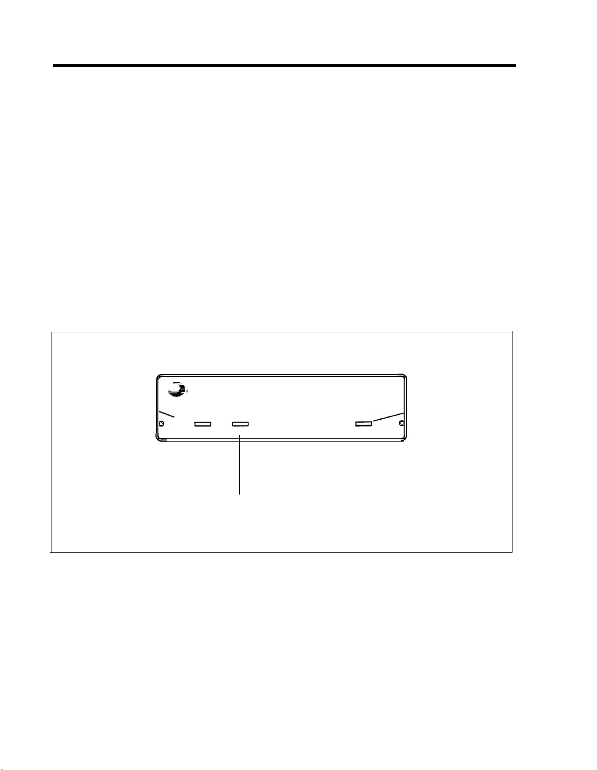
FRONT PANEL
There are three lights on the front panel as shown in
Figure 1-1. The lights indicate the following:
Lights when ac
AT&T
power is on
power
Blinking light indicates Steady light indicates
a problem. See
“Troubleshooting”
Light off when battery
is not fully charged
battery
MERLIN® Attendant
battery is fully charged
(when power light is on)
FIGURE 1-1 Front view of the MERLIN Attendant.
talking
Lights when
MERLIN
Attendant
answers and
monitors calls
1-2 Overview
• power
MERLIN Attendant is connected to a power source
when this light is on.
• battery
Table 1-1 describes the meaning of the different light
combinations when ac power is connected:
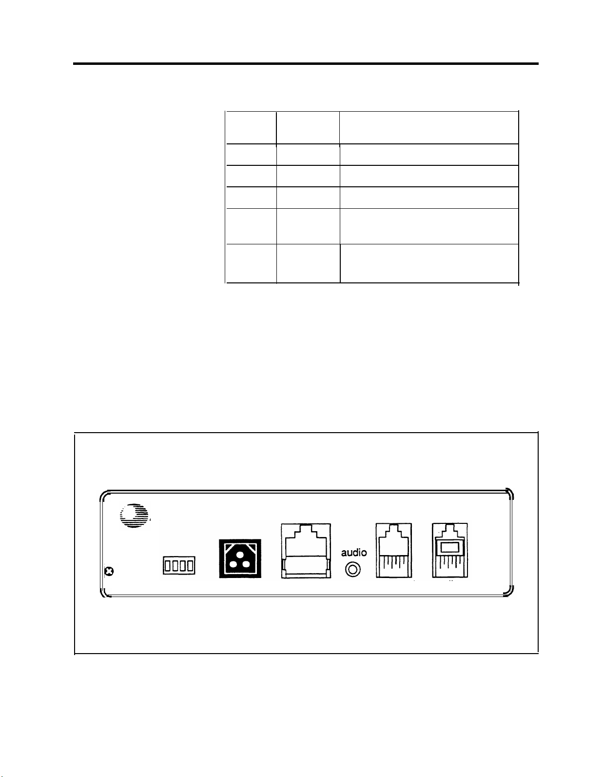
TABLE 1-1 Meaning of Power and Battery Lights
BACK PANEL
Power
Light
On
On
Off
Off
Battery
Light
Off
On
On
Off
Description
Battery charging
Battery fully charged
Unit operating on battery power
Unit not operating;
refer to “Troubleshooting”
On
Blinking
Out of Service code;
refer to “Troubleshooting”
• talking
This light is on whenever the MERLIN Attendant
answers and monitors a call.
The connectors and four setup switches on the back panel
are shown in Figure 1-2.
AT&T
off
•
on
reset setup
FIGURE 1-2 Back view of the MERLIN Attendant.
10VAC
serial i/o
out
reserved
to line
Overview 1-3

•
reset
This recessed button resets the MERLIN Attendant.
See “Troubleshooting” for details.
•
setup switches
There are four setup switches. Switches 1,2, and 3
control the MERLIN Attendant response to a power
outage as shown in Table 1-2; switch 4 is not used.
TABLE 1-2 Meaning of Setup Switch Settings
Switch
1
2
3
4
On (Down)
Recorded
announcements are
retained during a
power outage
Routes and other
programming
parameters are
retained during a
power outage
The MERLIN
Attendant continues to
answer calls during a
power outage
Not Used
Off (up)
Recorded
announcements are
erased during a power
outage
Routes and other
programming
parameters are reset to
defaults during a
power outage
The MERLIN
Attendant does not
answer calls during a
power outage
Not Used
1-4 Overview
CAUTION:
Attendant, be sure that switches 1 and 2 are
After connecting ac power to the MERLIN
on
(down).
With this setting, recorded announcements are saved up
to three hours during a power outage (if the battery is
fully charged) and routing plans and programming
parameters are retained up to eight weeks.

10 VAC
This is the power connector.
•
serial i/o
This is the connection for the printer to perform
diagnostic tests.
•
audio out
Not used
•
reserved
Not used
•
to line
This connects the MERLIN Attendant with the Basic
Telephone and Modem Interface 2 (BTMI-2) that
connects to a station module on the MERLIN Plus
system control unit. Install the MERLIN Attendant on
station intercom numbers as shown in Table 1-3.
TABLE 1-3 Intercom Numbers for MERLIN Attendant
MERLIN
Attendant
1st 11
2nd 12
3rd 13
Intercom
Number
Overview 1-5

Equipment and Location Requirements
The following equipment is supplied with the MERLIN
Attendant:
•
Power cord with transformer
• 8-foot, 6-wire modular phone cord
• Mounting plate
• User’s Guide
•
Basic Telephone and Modem Interface 2 (BTMI-2)
The BTMI-2 must be connected to a station module
housed in the MERLIN Plus system control unit (Release
1 or 2). Up to three MERLIN Attendant units (connected
to three BTMI-2s) can be connected to the module. The
units must be connected, in order, to stations 11, 12,
and 13.
NUMBER OF MERLIN Attendants REQUIRED
If a customer is using the MERLIN Attendant only for
backup call handling or after hours, only one MERLIN.
Attendant is required unless call traffic is heavy, as shown
in Table 1-4. When call traffic is heavy, the number of
MERLIN Attendants required at a site depends on the
number of calls the customer receives during peak hours.
Refer to Table 1-4 to determine how many
MERLIN Attendants are required.
TABLE 1-4 Calls Per Hour Table
If the customer does not know the number of calls the
Calls
Per Hour
15
15-30
more than 30
Number of
Units Needed
1
2
3
business gets during peak hours, you can estimate how
many MERLIN Attendants are required by asking the
1-6 Equipment and Location Requirements

customer how many incoming lines the business has. Then
refer to Table 1-5 to determine the number of MERLIN
Attendants required.
TABLE 1-5 Incoming Lines Table
LOCATION
Number
of Lines
Number of
Units Needed
3 or fewer 1
4-6 2
6-8 3
The number of units needed can also be affected by the
type of calls a customer receives. If there is significant
overflow of unanswered calls to the receptionist an
additional MERLIN Attendant may be needed.
The location for the MERLIN Attendant must meet the
following criteria:
•
Within 5 feet of a properly grounded ac power source
that is not controlled by a switch
NOTE:
If possible, the MERLIN Attendant should
share the same power source with the
MERLIN Plus system control unit. This is
recommended when the MERLIN Plus
system control unit is connected to an
Uninterruptible Power Supply (UPS).
•
Not more than 10 feet away from the MERLIN Plus
system control unit
•
A sufficient distance away from a heating or cooling
source to prevent exposure to temperatures beyond
0
32
F to 104
0
F (00 C to 40 0 C)
Equipment and Location Requirements 1-7

Administration Procedures
Before installing a MERLIN Attendant, you must install
and administer a Basic Telephone and Modem Interface 2
(BTMI-2) for each unit you are connecting. Perform all the
appropriate administration procedures from a multiline
MERLIN system telephone that is connected to the
MERLIN Plus system control unit.
IMMEDIATE CALL HANDLING
BACKUP CALL HANDLING
Use the following procedure to administer the
MERLIN Attendant for immediate call handling in the
MERLIN Plus system:
1
Program all common lines for “delayed ring” at the
receptionist’s voice terminal (station 10) and
administer a Privacy button.
Program all common lines for “no ring” at all other
2
stations.
3
Use the receptionist’s voice terminal to program any
personal lines for “no ring” at the MERLIN Attendant.
Use the following procedure to administer the
MERLIN Attendant for backup call handling in the
MERLIN Plus system:
1 Program a Privacy button for all stations with ringing
lines.
2 Program all common lines for “no ring” at all other
stations.
3 Program Day and/or Night Answer Delay as required
on the MERLIN Attendant for a minimum of five ring
cycles.
1-8 Administration Procedures
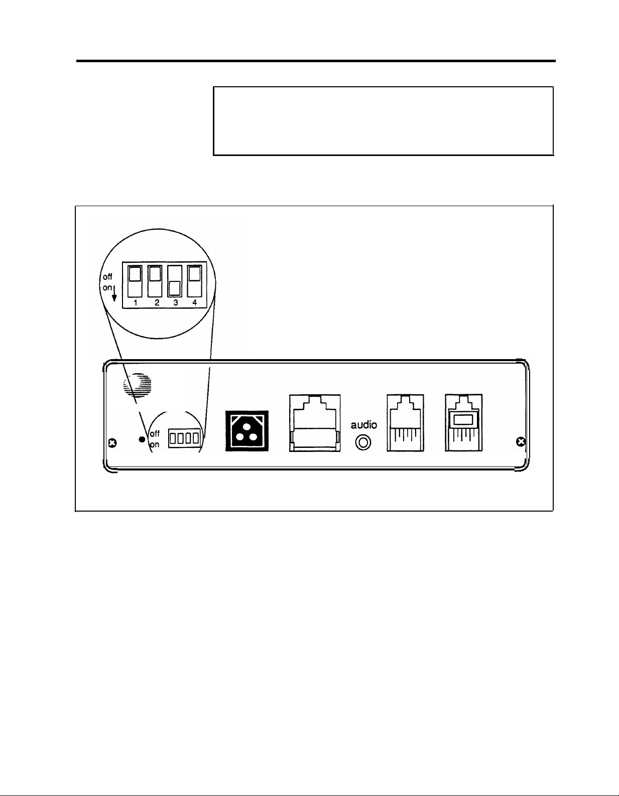
Connecting the MERLIN Attendant
CAUTION: Before initial installation of the MERLIN
Attendant, set switches 1 and 2 on the back panel to
off (up).
Follow the steps below to install the MERLIN Attendant:
AT&T
out
reset setup
10VAC
serial i/o
FIGURE 1-3 Setup Switch Positions for Installing Unit.
1 For each MERLIN Attendant port:
a Install a Basic Telephone and Modem Interface 2
(BTMI-2) on the MERLIN Plus system control
unit. Install BTMI-2s on station intercom numbers
as shown in Table 1-6.
reserved to line
Connecting the MERLIN Attendant 1-9
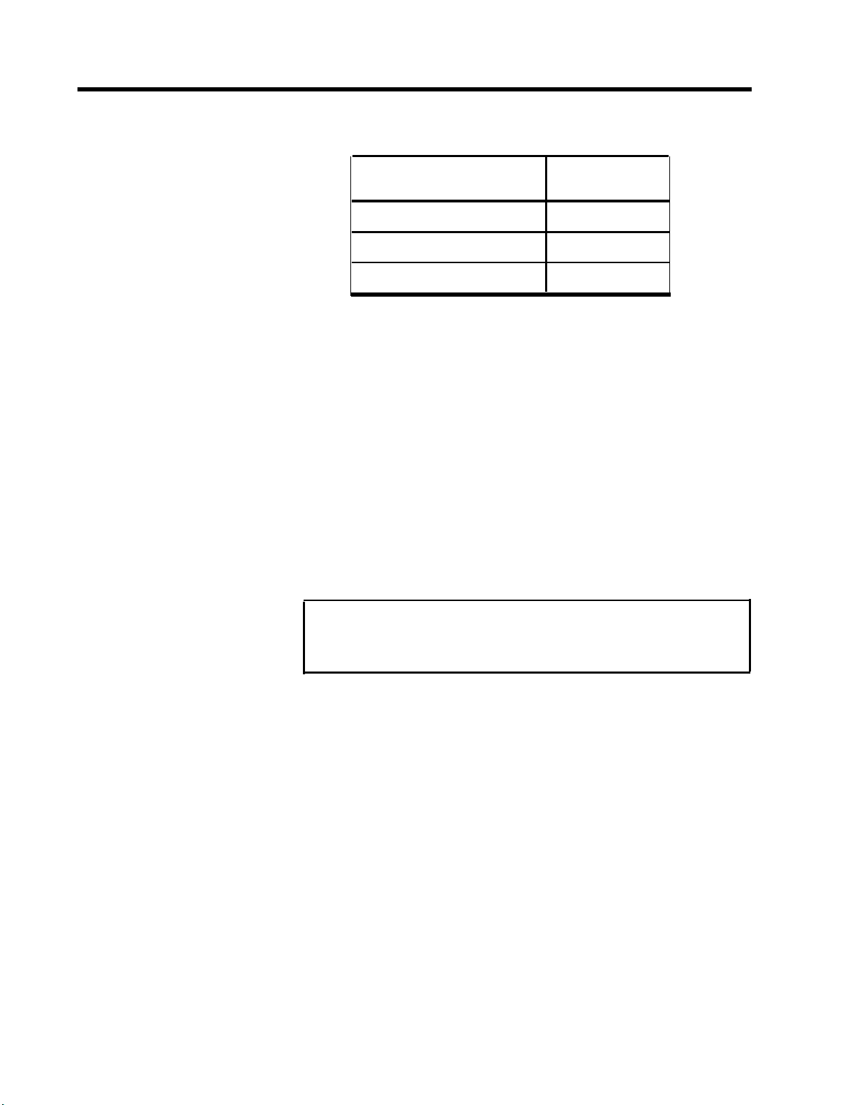
TABLE 1-6 Installing BTMl-2s on StatIon Intercom Numbers
Number of
MERLIN Attendants
1
2
3
Intercom
Number
11
11 and 12
11, 12, and 13
b Switch the BTMI-2 to “data” mode.
2
Place the MERLIN Attendant on a table or desktop, or
mount it using the mounting bracket:
a Using a #10 or smaller screw (wood, sheet metal,
concrete), attach the wall mounting bracket to a
vertical wall surface so that the hook end of the
bracket is down.
b Locate the keyhole opening on the underside of the
MERLIN Attendant with the hook on the bracket.
Slide the unit over the hook and down to secure.
CAUTION: Do not stack multiple MERLIN
Attendants; this will damage the units.
3
Make sure setup switches 1 and 2 are off, then plug one
end of the modular phone cord into the jack on the
back of the MERLIN Attendant labeled “to line.”
(See Figure 1-3.)
4
Plug the other end of the modular phone cord into the
BTMI-2. (See Figure 1-4.)
Plug one end of the power cord into the 10 VAC power
5
connector on the MERLIN Attendant.
1-10 Connecting the MERLIN Attendant
 Loading...