

Page 1

555-640-110
Issue 1
March, 1996
4ABLEOF
#ONTENTS
MERLIN LEGEND ®
Communications System
Releases 3.1 and 4.0
Feature Reference
Graphics © AT&T 1988
Page 2

Features
shows where information can be found about features and
Index of
lists features according to tasks typically performed with
This book is designed to provide both summary and detailed information about
every feature in the MERLIN LEGEND Communications System. For each
feature, the following types of information are provided, as applicable:
■
At a Glance. Summary information about the feature, including, for
example, users affected, telephones supported, programming code(s),
and factory settings.
■
Description. A detailed description of the functions and typical uses of
the feature.
■
Considerations and Constraints. An explanation of exceptions and
unusual conditions pertaining to the feature.
■
Mode Differences. An explanation of variations in the use of the feature
in the different modes supported by the communications system.
■
Telephone Differences. An explanation of variations in the use of the
feature with different telephones.
■
Feature Interactions. A list of issues and considerations to be aware of
when using a feature in conjunction with another feature.
For easy reference, features are covered in alphabetical order. The “Index of
Feature Names”
other system components that may have been renamed or reorganized in this
release of the communications system and related products. The “
Features by Activity”
the system. Use these, or the index at the back of the book, when you’re not
sure which entry you should consult.
Feature Reference
1
Page 3

Feature Reference
Index of Feature Names
Feature Name See
A
Alarm Alarm
Alarm Clock Alarm Clock
Allowed Lists Allowed/Disallowed Lists, Night Service
Area Code Tables Automatic Route Selection
Attendant Barge-In Barge-In
Attendant DSS Direct Station Selector-MLX
Attendant Message Waiting Messaging
Attendant console—display Display
Attendant console—Switched Loop Queued Call Console
AUDIX Voice Power
Authorization Codes Authorization Codes
Auto Answer—All Auto Answer All
Auto Answer—Intercom Auto Answer Intercom
Auto Dial Auto Dial
Auto intercom Auto Answer Intercom
Auto Login/Logout (calling group) Group Calling
Automated Attendant Service Integrated Administration
Automatic Answer (data management) Auto Answer All
Automatic Callback Callback, Remote Access
Automatic Completion Transfer
Automatic Extended Call Completion Queued Call Console
Automatic Hold or Release Queued Call Console, Hold
Automatic Line Selection Automatic Line Selection and Ringing/Idle
Automatic Maintenance Busy Automatic Maintenance Busy
Automatic Route Selection (ARS) Automatic Route Selection
Autoqueuing Remote Access
Integrated Administration
Line Preference
B
Barge-In Barge-In
Basic Rate Interface Basic Rate Interface
‡ See
2 Index of Feature Names
Data and Video Reference
for further information.
‡
Page 4

Feature Reference
Feature Name See
C
Call by Call Services Table Primary Rate Interface (PRI) and T1
‡
Call completion Transfer (One-Touch)
Queued Call Console (Extended)
Call Answer Service Integrated Administration
Call Coverage Coverage
Call Forward(ing)/Following Forward and Follow Me
Call Park Park
Call Pickup Pickup
Call Pickup—directed Pickup
Call Pickup—group Pickup
Call Records Station Messaging Detail Recording (SMDR)
Call Restrictions Calling Restrictions
Call Waiting Call Waiting
Callback Callback
Callback Queuing Callback
Calling Group Group Calling, Integrated Administration
Calls-In-Queue Alarm Group Calling, Queued Call Console (QCC)
Camp-On Camp-On
Cancel Delivered Message Messaging
Centralized Telephone Programming Programming
†
Centrex Centrex Operation
Class of Restriction Remote Access
Common Administration Integrated Administration
Conference Conference
Consultation Transfer Transfer
Coverage Delay Interval Coverage
Coverage Group Coverage, Integrated Administration
Coverage Inhibit Coverage
Coverage On/Off Coverage
Coverage Coverage
† See
‡ See
System Programming
Data and Video Reference
for further information.
for further information.
Index of Feature Names 3
Page 5

Feature Reference
Feature Name See
D
Default Local and Toll tables Automatic Route Selection
Delay Announcement Group Calling
Delay Ring Ringing Options
Delete Message Messaging
Deliver Message Messaging
Dial by name (display feature) Directories
Dial Plan System Renumbering
Dial Plan Routing Table Primary Rate Interface (PRI) and T1
Dial Tone Inside Dial Tone
Dialed number Display
Digital Data Ports
Digital Data Calls Digital Data Calls
‡
‡
Digits in Extension System Renumbering
Direct Dept. Calling (Hunting, Hunt Groups) Group Calling
Direct Facility Termination (DFT) Personal Lines
Direct Group Calling (DGC) Group Calling
Direct Inward System Access (DISA) Remote Access
Direct-line console Direct-Line Console
Direct Pool Termination (DPT) Pools
Direct station selector Direct Station Selector:MLX
Directory built into PBX Directories
Directory of System Speed Dial numbers Speed Dial
Directory of extension numbers Directories
Behind Switch Operation Recall/Timed Flash, Centrex Operation
Barrier code Remote Access
Bridging of station lines on multiline set Personal Lines, System Access/Intercom
Buttons
Disallowed Lists Allowed/Disallowed Lists
Display Display
Display of name associated with station Labeling
Display prompting Display
Distinctive Ringing Ringing Options
Do Not Disturb Do Not Disturb
Drop Conference
‡
‡ See
Data and Video Reference
4 Index of Feature Names
for further information.
Page 6

Feature Reference
Feature Name See
E
Executive Barge-in Barge-In
Extended call completion Queued Call Console
Extended Station Status Extension Status
Extension Auto Dial Auto Dial
Extension Directory Directories, Integrated Administration
Extension Pickup Pickup
Extension programming Programming
Extension Status Extension Status, Group Calling
†
F
Facility alpha/number for incoming calls Labeling
Facility Restriction Level (FRL) Automatic Route Selection
Fax Attendant Integrated Administration
Fax Extension Fax Extension
Fax message waiting Messaging
Feature feedback Display
Flexible Numbering System Renumbering
Follow me Forward and Follow Me
Forced Account Code Entry Account Code Entry/Forced Account Code
Entry
Forward Forward and Follow Me
G
General Pickup Pickup
Group Assignment Night Service
Group Call Pickup Pickup
Group Calling Group Calling, Extension Status
Group Coverage Coverage
Group Paging (Speakerphone) Paging
Group Pickup Pickup
† See
System Programming
for further information.
Index of Feature Names 5
Page 7

Feature Reference
Feature Name See
H
Hands-Free Answer on Intercom (HFAI) Auto Answer Intercom
Hands-Free Unit Auto Answer Intercom
Handset Mute Headset Options
Headset Auto Answer Headset Options
Headset Disconnect Headset Options
Headset/Handset Mute Headset Options
Headset Hang Up Headset Options
Headset Operation Headset Options
Headset Options Headset Options
Headset Status Headset Options, Queued Call Console
Hold Hold
Hold Reminder station Display
Hold Return Queued Call Console
Hotel mode Extension Status
Hunt Groups Group Calling
Hunt type Group Calling
I
ICOM buttons System Access/Intercom Buttons
Identification of stations being covered
on covering party’s display Display
Idle Line Preference Automatic Line Selection and Ringing/Idle
Line Preference
Immediate ring Ringing Options
Incoming Call Line Identification (ICLID) Caller ID
Individual Coverage Coverage
Individual Paging Paging
Individual Pickup Pickup
Information Service Integrated Administration
Integrated Administration Integrated Administration
Inside Auto Dial Auto Dial
Inside Dial Tone Inside Dial Tone
Inspect Inspect
Inspect screen Display
Intercom (ICOM) Buttons System Access/Intercom Buttons
Intercom dialing System Access/Intercom Buttons
ISDN/BRI Interface Basic Rate Interface (BRI)
ISDN/PRI Interface Primary Rate Interface (PRI) and T1
‡ See
Data and Video Reference
for further information.
‡
‡
6 Index of Feature Names
Page 8

Feature Reference
MLX
Feature Name See
L
Labeling Labeling
Last Number Dial Last Number Dial
Last Number Redial Last Number Dial
Leave Message Messaging
Leave Word Calling Messaging
Line Pickup Pickup
Line Request Line Request
Line/trunk pool button access Pools
Line/trunk queuing Callback
Loudspeaker Paging Paging
M
Maintenance Alarm Alarm
Maintenance Busy Automatic Maintenance Busy
Manual signaling Signal/Notify
Menu-based feature activation Display
Menu-based station programming Programming
MERLIN Attendant™ AT&T Attendant
MERLIN II System Display Console Direct-Line Console, Direct Station
Selector—
Message (fax) Messaging
Message Center operation Queued Call Console
Message Drop Service Integrated Administration
Message indicator Messaging
Message Status (operator) Messaging
Message Waiting Receiver Group Calling
Messaging Messaging
Microphone Disable Microphone Disable
Missed Reminder Reminder Service
Modem pooling
Multi-Function Module Multi-Function Module
Music On Hold Music On Hold
Mute Microphone Disable
Mute, Headset/Handset Headset Options
§
‡ See
Data and Video Reference
for further information.
Index of Feature Names 7
Page 9

Feature Reference
Feature Name See
N
N11 table Automatic Route Selection
Name/number of internal caller Display
Next Message Messaging
Night Service Night Service
No Ring option Ringing Options
Notify Signal/Notify
Numbering Plan System Renumbering
O
On- or off-hook queuing Callback
One-Touch Hold Transfer
One-Touch Transfer Transfer
Operator Automatic Hold Hold
Operator Hold Timer Hold
Originate Only System Access/Intercom Buttons
Outside Auto Dial Auto Dial
Outward Restriction Calling Restrictions, Night Service
P
Page All Paging
Paging Paging
Park Park
Patterns Automatic Route Selection
Personal Directory Directories
Personal Speed Dial Speed Dial
Personalized Ring Ringing Options
Pickup, Call Waiting Call Waiting
Pool Dial-Out Code Restriction Calling Restrictions
Pool routing Automatic Route Selection
Pools Pools
Position Busy Backup Queued Call Console
Posted Messages Messaging
PRI Primary Rate Interface (PRI) and T1
Primary Coverage Coverage
‡ See
§ See
Data and Video Reference
MERLIN LEGEND Communications System Modem Pooling
for further information.
applications note.
‡
8 Index of Feature Names
Page 10

Feature Reference
Feature Name See
Primary Rate Interface (PRI) Primary Rate Interface (PRI) and T1
Prime line Centrex Operation
Principal user Personal Lines, System Access/Intercom
Buttons
Printer Station Message Detail Recording (SMDR)
Priority call ringing Ringing Options
Privacy Privacy
Programming Programming, Integrated Administration
‡
Q
Queue Priority Queued Call Console
Queued Call Console Queued Call Console
R
Recall Recall/Timed Flash
Reminder Service Reminder Service
Remote Access Remote Access
Remote Administration
Remote Call Forwarding Forward and Follow Me
Remote programming
Restrictions Calling Restrictions
Retrieve Message Messaging
Return Call Messaging
Return Ring Interval Queued Call Console
Ring Buttons System Access/Intercom Buttons
Ring Timing options Ringing Options
Ringback (Transfer Audible) Transfer
Ringing/Idle Line Preference Automatic Line Selection and Ringing/Idle
Ringing options Ringing Options
Rotary signaling Touch-Tone or Rotary Signaling
Routes per pattern Automatic Route Selection
Routing by Dial Plan Primary Rate Interface (PRI) and T1
†
†
Line Preference
S
SA buttons System Access/Intercom Buttons
Saved Number Dial Saved Number Dial
Scroll Messaging
† See
‡ See
System Programming
Data and Video Reference
for further information.
for further information.
Index of Feature Names 9
Page 11

Feature Reference
Feature Name See
Second Dial Tone Timer Second Dial Tone Timer
Secondary Coverage Coverage
Selective Callback Callback
Send All Calls Do Not Disturb
Send/Remove Message Messaging
Send Ring Ringing Options
Set Up Space System Renumbering
Shared System Access System Access/Intercom Buttons
Signaling Signal/Notify
Six-digit screening Automatic Route Selection
SMDR Station Message Detail Recording (SMDR)
Speakerphone Paging Paging
Special Numbers Pattern Automatic Route Selection
Special Services Selection Table Primary Rate Interface
Speed Dial Auto Dial, Directories, Speed Dial
SPM Programming
Station Conference—External Parties Conference
Station Conference—Total Parties Conference
Station DSS auto dial Direct Station Selector
Station lines System Access/Intercom Buttons
Station Message Detail Recording Station Message Detail Recording (SMDR)
Station programming Programming
Station-to-Station Messaging Messaging, Signal/Notify
Switched 56 Primary Rate Interface (PRI) and T1
Switchhook (Flash) Recall/Timed Flash
Supplemental Alert Adapter Multi-Function Module
Switched Loop Console Queued Call Console
System Access buttons System Access/Intercom Buttons
System Directory Directories
System Numbering System Renumbering
System Programming Programming
System Programming and Maintenance Programming
System Speed Dial Speed Dial
†
‡
†
†
T
T1 Interface (DS1) Primary Rate Interface (PRI) and T1
Three-Digit Numbering System Renumbering
Time-day-date (display) Display
Timed flash Recall/Timed Flash
† See
‡ See
10 Index of Feature Names
System Programming
Data and Video Reference
for further information.
for further information.
‡
Page 12

Feature Reference
Feature Name See
Time of day routing
Timer
Tip/Ring devices
Toll Restriction Calling Restrictions
Toll Type Toll Type
Touch-tone receivers (TTRs) Touch-Tone or Rotary Signaling
Touch-tone signaling Touch-Tone or Rotary Signaling
Transfer Transfer
Transfer Audible Transfer
Transfer Return Identification Display
Transfer Return interval Transfer
Trunk Pools Pools
Trunk-to-Trunk transfer Transfer
TTRs Touch-Tone or Rotary Signaling
Two-Digit numbering System Renumbering
Automatic Route Selection
Timer
U
UDC/DDC Group Calling
Unrestricted Restriction Calling Restrictions
V
Video Conferencing
VMI (voice messaging interface) Ports Group Calling
Voice announce Paging
Voice announce disable Voice Announce to Busy
Voice announce inside calls Paging, System Access/Intercom buttons
Voice announce on busy stations Voice Announce to Busy
Voice Announce Transfer Transfer
Voice buttons System Access/Intercom Buttons
Voice mail message waiting Messaging
Voice mail systems Integrated Administration
Voice messaging systems Integrated Administration
Index of Feature Names
11
Page 13

and
Feature Reference
Index to Features by Activity
The index in this section lists system features according to the activities that
people typically perform. (You can also use the index at the back of the book to
find the features that support particular activities, but this list supplies more
detail.) Operator features are not covered exhaustively here, because they are
described in detail in the entries: “Direct-Line Console,” “Direct Station
Selector:MLX,”
to the following categories:
■
Basic Calling and Answering
Answering calls
Conferencing and joining calls
Dialing
Paging
Putting a call on hold
Using the system from an outside phone
■
Covering Calls or Having Calls Covered
“Queued Call Console.” This index lists features according
When you are covering calls
When someone is covering your calls
■
Timekeeping
■
Calling Privileges and Restrictions
To prevent people from making calls
To allow calls
Other calling privileges
■
Messaging
■
System Manager Features
■
Special Operator and Calling Supervisor Features
Look for the activity in the first column. In the second column, find out who can
perform the activity described. The third column cites the name of the feature
that you should look up in order to get more information.
Index to Features by Activity
13
Page 14

Feature Reference
Basic Calling and Answering For Feature Name
Answering calls
And seeing who is calling you from another extension Display phones Display
And seeing who is calling you from outside MLX display
phones
And identifying the type of call according to the ring All Ringing Options
At another extension All Pickup
At a line not on your phone All Pickup
At a line you share with others All System Access/Intercom
For another person or group of people. See
“Covering calls or having calls covered”
If you are a calling supervisor for people answering
calls
If you are an operator DLC and QCC
If you are part of a group All Group Calling
Waiting for you, after you hear call-waiting tone All Call Waiting
That come to your extension while you’re at another
extension
And then disconnect it, without using the handset or
Speaker button
Using a Hands-Free Unit, without lifting the handset Analog multiline
Using a headset MLX Headset Auto Answer
Using a modem, fax machine, or headset Analog multiline Auto Answer All
All Coverage
DLC and QCC
operators only
operators only
All Forward and Follow Me
All Recall/Timed Flash
w/out speaker
Display
Caller ID
Primary Rate Interface (PRI)
Buttons
Personal Lines
Centrex Operation
Personal Lines
System Access/Intercom
Buttons
Forward and Follow Me
Queued Call Console
Direct-Line Console
Group Calling
Direct-Line Console
Queued Call Console
Direct Station Selector: MLX
Group Calling
Extension Status
Direct-Line Console
Queued Call Console
Direct Station Selector: MLX
Extension Status
Auto Answer Intercom
14 Index to Features by Activity
Page 15

Feature Reference
Conferencing and joining calls
Conferencing inside and outside parties where the
inside parties do not share a line
Joining calls of inside parties who share a line All System Access/Intercom
Preventing others from joining your calls All except QCC Privacy
Joining a caller and the extension he or she wants to
reach
All Conference
Buttons
Personal Lines
Centrex Operation
All except
operators
Transfer
Dialing
An inside call All System Access/Intercom
Buttons
Centrex Operation
An outside call All System Access/Intercom
Buttons
Pools
Personal Lines
Centrex Operation
An inside or outside number with one touch All except
single-line and
QCC
An inside or outside number with one touch Operators with
MLX phones or
System Display
Consoles only
A call from anther extension, using your own calling
privileges
An inside call to anyone in a group of people All Group Calling
An Account Code, for billing to a project or client,
during or before a call
By entering a 3-digit code for a party that people in
your company call often
By entering a 2-digit code for a party you call often
(phones with 10 or fewer buttons)
By selecting a name from the display All Directories
A person who has left a message on your display,
with one touch
Outside of normal office hours All Night Service
A number you dialed before All except QCC Last Number Dial
A busy extension to reach it when it’s available All except QCC Callback
All Authorization Codes
All Account Code Entry/Forced
All Speed Dial
All Speed Dial
Display phones
only
Auto Dial
Direct Station Selector: MLX
Account Code Entry
Messaging
Saved Number Dial
Camp-On
Index to Features by Activity 15
Page 16

Feature Reference
A busy line to have your call placed when the line
is available
When you want to interrupt a call at a busy extension
or one with Do Not Disturb on
Using a special long-distance service such as
Megacom WATS
A voice mail box All Direct Voice Mail
Change the Extension Directory to accommodate
new or changed extensions.
Change the System Directory to accommodate
business needs.
All except QCC
(and single-line
and cordless or
wireless, for
Line Request)
Operators only Barge-In
System
managers
(to set up)
System
managers only
System
managers only
Callback
Line Request
Primary Rate Interface (PRI)
Pools
Automatic Route Selection
Labeling
Labeling
Paging
One person at your company who has a
speakerphone and is not a QCC operator or at a
single-line phone
Several people at your company who have
speakerphones and are not QCC operators or at
single-line phones
All the people at your company who have
speakerphones and are not QCC operators or at
single-line phones
Over your company’s loudspeaker system All Paging
Prevent voice-announced calls from coming in over
your speakerphone, or allow them
All System Access/Intercom
Buttons
All Paging
Pickup
All Paging
Pickup
Pickup
Analog multiline
and MLX
Voice Announce to Busy
Putting a call on hold
At your own extension, so that you can pick it up All except
single-line
At your own extension, so that you can pick it up Single-line Recall/Timed Flash
At your own extension, so that you or someone who
shares a line can pick it up
At your own extension, so that you or someone who
shares a line can pick it up
At your own extension, to put an outside call on hold
automatically in order to transfer to another
extension with a shared line or button
All Hold
All Hold
All Transfer
Hold
System Access/Intercom
Buttons
Personal Lines
Centrex Operation
System Access/Intercom
Buttons
Personal Lines
Centrex Operation
16 Index to Features by Activity
Page 17

Feature Reference
At your own extension, so that anyone can pick it up
after you page them
At one of several reserved extensions, so that anyone
can pick it up after you page them
Automatically DLC operators
All except QCC Park
Operators only Park
Hold
only
Direct-Line Console
Using the system from an outside phone
To gain access to the system as if you were on an
inside extension
To receive calls that come to your system
extension
N/A Remote Access
N/A Forward and Follow Me
Covering Calls or Having Your Calls Covered
When you are covering calls
As an operator DLC and QCC
operators only
As a calling supervisor for people covering calls DLC and QCC
operators only
As a member of a group All Group Calling
And you want to adjust the ringing at the button
where calls come in
All except
single-line
Direct-Line Console
Queued Call Console
Direct Station Selector
Direct-Line Console
Queued Call Console
Direct Station Selector
Group Calling
Extension Status
Coverage
Coverage
Ringing Options
When your calls are being covered
By someone who shares a line All System Access/Intercom
Buttons
Occasionally All Forward and Follow Me
By voice mail All Coverage
Regularly All Coverage
And you want to adjust or remove the ringing at the
button(s) where covered calls arrive
All except
single-line
Coverage
Ringing Options
Timekeeping
To set others’ phones to ring at a certain time as a
reminder
To set your own phone to ring at a certain time as a
reminder
To set the alarm clock on your telephone Display
DLC operators
only
All Reminder Service
telephones
only
Reminder Service
Alarm Clock and Timer
Index to Features by Activity 17
Page 18

Feature Reference
To set the time at your telephone Display
telephones
only
To set the timer for calls or other activities Display
telephones
only
To set the systemwide time System
manager only
Calling Privileges and Restrictions
To prevent people from making calls
To your extension All except
operator
To your extension when your phone is too busy to
take any more calls or you must be away
from your phone
To outside numbers System
To toll numbers System
To certain numbers or area codes System
Outside of normal business hours System
On certain outside lines in a Hybrid/PBX system System
To allow calls
To certain numbers or area codes System
Outside of normal business hours System
QCC only Queued Call Console
manager only
manager only
manager only
manager only
manager only
manager only
manager only
Alarm Clock and Timer
Alarm Clock and Timer
See
System Programming.
Privacy
Do Not Disturb
Calling Restrictions
Toll Type
Calling Restrictions
Automatic Route Selection
Pools
Toll Type
Allowed/
Disallowed Lists
Night Service
Automatic Route Selection
Pools
Toll Type
Allowed/
Disallowed Lists
Speed Dial (System
Speed Dial)
Night Service
18 Index to Features by Activity
Page 19

Feature Reference
Other calling privileges
To use your own calling privileges at others’
extensions
To enter your password for off-hours calls All Night Service
All Authorization Codes
Customizing Your Phone
Give your phone its own distinctive ring.
Change the way your phone rings when you're
already on a call.
Delay or remove the ring from an outside, SA,
or ICOM line button.
Change the volume levels for ringing,
conversations on the handset, and
conversations on the speakerphone.
Change the language used (English, French, or
Spanish) at your extension; this also changes the
clock, which is 12-hour for English and 24-hour for
French or Spanish.
All
All
All except
single-line
MLX only Volume
MLX display
phones only
Ringing Options
Ringing Options
Ringing Options
Language
Messaging
Leaving Messages
Turn an extension’s Message light on or off to
indicate that you have a message for the party.
Call and let a co-worker with a display phone know
that you have called.
Let a co-worker with a display phone know that you
wish to speak with him or her, without calling.
Let a co-worker with a multiline phone know that you
wish to speak with him or her, without calling.
Post a specific message (such as, OUT TO LUNCH)
for co-workers who have display phones.
Cancel a message left for a co-worker who has a
display phone.
Operators only Messaging (Send/Remove
Message)
All Messaging (Leave Message)
All except QCC Messaging (Leave Message)
Signaling/Notify
All except QCC Signaling/Notify
All except
single-line
All Messaging (Leave Message)
Messaging (Posted Messages)
Receiving Messages
Read messages. Display phones
only
Turn off Message light. All Messaging
Delete messages. Display phones
only
Return a call from a co-worker who has left
a message.
Display phones
only
Messaging
Messaging
Messaging
Controlling Messaging
Change the posted messages that users can
choose from.
System
manager only
Labeling
Index to Features by Activity 19
Page 20

Feature Reference
Change the extension information that appears on
display telephones that have messages.
Set up voice messaging system to take calls. System
Set up extensions to receive messages from a fax
machine that has a delivery for them.
Set up calling groups to receive messages from
co-workers.
System Manager Features
(for System Manager or Programmer Only)
Customizing the system
Set up account codes so that calls can be billed or
tracked to a specific client or project.
Set up which line is selected when a user lifts the
handset or presses the Speaker button.
Change extension numbers for extensions, adjuncts,
trunks, telephones, ranges of extensions on a DSS,
Automatic Route Selection, calling groups, Idle Line
Access, Listed Directory Number, paging groups,
park zones, Pools, or Remote Access.
Change the overall system numbering plan; for
example, change to 2-, 3-, or a variable number
of digits for extension numbers.
Modify the line buttons (SA or ICOM) available on a
user’s telephone: change, add, or delete.
Adjust the ringing at an extension, including one
with a single-line phone or MFM.
Set up special phones to be used for incoming and
outgoing calls during a commercial power failure.
Adjust the system dial tone to accommodate a voice
messaging system or modem.
Control what a caller hears while waiting for the
system (during transfer, while on hold, or
during other operations where the caller must wait).
Set up an adapter connected to an MLX extension to
support a fax machine, modem, or other device.
Change the language (English, French, or Spanish)
used in System Programming and Maintenance
(SPM) software.
Change the language (English, French, or Spanish)
used in Station Message Detail Recording (SMDR)
and programming reports.
Set up Transfer for one-touch transfer or
automatic hold.
System
manager only
manager only
System
manager only
System
manager only
N/A Account Code Entry/Forced
All telephones Automatic Line Selection and
All System Renumbering
All System Renumbering
All except
single-line
For
single-line/MFM
N/A Power Failure Transfer
N/A Inside Dial Tone
N/A Music On Hold
N/A
System
manager or
programmer
N/A Labeling
All Transfer
Labeling
Group Calling
Messaging
Messaging
Account Code Entry
Ringing/Idle Line Preference
System Access/Intercom
Buttons
Ringing Options
Coverage
Multi-Function Module
Labeling
20 Index to Features by Activity
Page 21

Feature Reference
Directories
Change the Extension Directory to accommodate
new or changed extensions.
Change a user’s Personal Directory listings. MLX display
Change the names listed with System Directory
entries to accommodate business needs.
N/A Labeling
Labeling
phones only
N/A Labeling
Getting reports
Get a report on incoming and outgoing calls,
including account codes, if programmed.
Get a report on the way the system is programmed. N/A Station Message Detail
N/A Station Message Detail
Recording (SMDR)
Recording (SMDR)
Lines and trunks
Take an outside line out of service when there is a
problem with it.
In Hybrid/PBX mode, assign lines that can be
answered without operator involvement.
In Behind Switch mode, allow Conference, Transfer,
and Drop buttons to access host features.
N/A Automatic Maintenance Busy
All telephones Personal Lines
N/A Recall/Timed Flash
Messages
Change the language used (English, French, or
Spanish) systemwide or at an extension; this also
changes the clock, which is 12-hour for English and
24-hour for French or Spanish.
Change the posted messages that users can
choose from.
Change the extension information that appears on
display telephones with inside calls and messages.
MLX display
phones only
N/A Labeling
N/A Labeling
Language
Operators
Allow a QCC operator to join callers and extensions
more rapidly.
Find out about the Alarm button on operator
consoles or set up a special light or bell to
signal a system problem.
Set up a group of fax machines to take calls. N/A Group Calling
Set up voice messaging system to take calls. N/A Group Calling
Prevent DLC operators from accidentally
disconnecting callers.
Find out what to do when callers on hold are being
disconnected.
N/A Queued Call Console
Operator
consoles
N/A Hold
N/A Hold
Alarm
Direct-Line Consoles
Index to Features by Activity 21
Page 22

Feature Reference
Make your system more secure from toll fraud. N/A Calling Restrictions
Remote Access
Forward and Follow Me
Automatic Route Selection
Group Calling
Troubleshooting
Correct problems that users are having with the
switchhook, Recall, or Flash button.
N/A Recall/Timed Flash
Special Operator and Supervisor Features
Join a caller and the extension he or she wants to
reach.
Find out about the Alarm button that signals a
system problem.
Find out about the Alarm button that signals too
many calls waiting in line for your attention
or your group’s attention.
Activate Night Service for system use outside of
normal business hours.
Set up the way calls are distributed to calling group
members.
Monitor others’ calls. N/A Direct-Line Console
Set up a device to answer calls when a group is
unavailable to take them.
Log a calling group member in or out. Operator
Log a delay announcement device for a group
in or out.
Allow DLC operators to place calls on hold
automatically.
Turn an extension’s Message light on or off to
indicate that you have a message for the party.
Operator
consoles
Operator
consoles
Operator
consoles
Operator
consoles
System
manager only
System
manager only
consoles
Operator
consoles
System
manager only
Operators only Messaging (Send/Remove
Direct-Line Console
Queued Call Console
Alarm
Group Calling
Auto Dial
Night Service
Group Calling
Queued Call Console
Direct Station Selector
Extension Status
Group Calling
Group Calling
Group Calling
Extension Status
Group Calling
Hold
Direct-Line Consoles
Message)
Understanding and Customizing Your
Telephone
Learn about the display on your telephone. Display
telephones
Set contrast on your telephone. Display
telephones
except BIS-22D
Display
Display
22 Index to Features by Activity
Page 23

Feature Reference
Use the line buttons on your telephone. All System Access/Intercom
Buttons
Personal Lines
Pools
Centrex Operation
Program buttons. Multiline
telephones
Change the ringing sound on your telephone. All Personalized Ringing
Change the number of times calls ring. All Ringing Options
Use the display to screen incoming calls. MLX display
phones only
See what features are programmed on telephone
buttons.
For noisy environments: turn off the microphone
at an MLX telephone (except a QCC) so that
a user can hear voice announcements but must
lift the handset to respond.
MLX display
phones only
System
manager only
Programming
Inspect
Inspect
Microphone Disable
Index to Features by Activity 23
Page 24
Feature Reference
Abbreviated Ring
See “Ringing Options.”
Account Code Entry/Forced Account Code Entry
At a Glance
Users Affected Telephone users, operators
Reports Affected Extension Directory
Extension Information
SMDR
Mode All
Telephones All touch-tone telephones
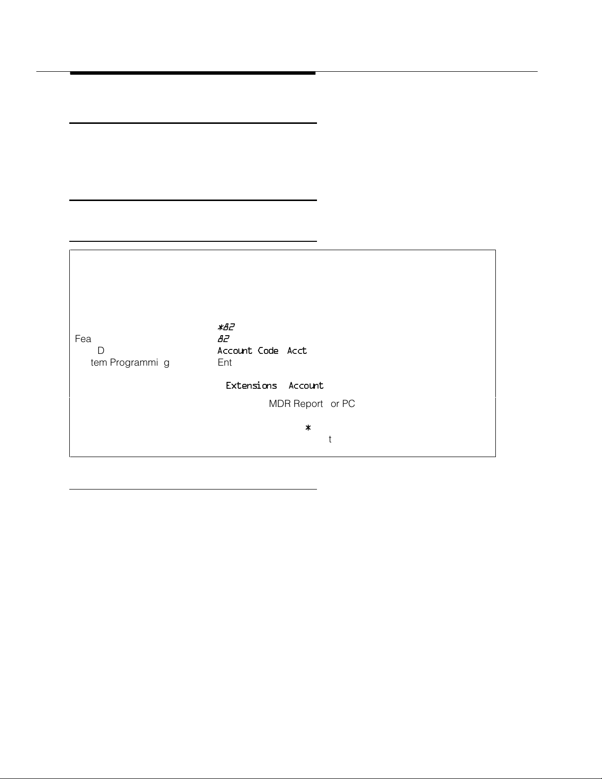
Programming Code
Feature Code
MLX Display Label
System Programming Enter extensions required to use account codes before
*82
82
Account Code [Acct
making an outside call:
•
Extensions→Account
]
Hardware Printer for SMDR Reports or PC and printer equipped with
AT&T CAS software needed for Account Code Reports
Maximums 16 characters (0–9, *)
Factory Settings Forced Account Code not assigned to any extensions
Description
Use Account Code Entry to enter account codes (developed by accounting or
administrative personnel) for outside calls, both incoming and outgoing. These
codes appear on Station Message Detailed Recording (SMDR) reports, along
with other call information, and are used for billing or cost accounting to identify
outgoing calls with a project, client, or department. You can enter an account
code before or during a call or not at all. You can also change, correct, or
cancel an account code while the call is in progress.
Forced Account Code Entry is similar, but affects only outgoing calls and
requires a caller to enter an account code before placing an outside call. You
can change or correct an account code while a call is in progress, but you
cannot cancel it.
24 Abbreviated Ring
Page 25

Feature Reference
To enter, change, or correct an account code during a call, activate the feature
and enter the account code. Only the person who enters the account code
hears the tones generated by dialing the account code number. To cancel an
account code (when permitted), activate the feature and exit without entering a
code.
With Forced Account Code Entry, if you try to make an outside call without
entering an account code, the following occurs:
■
If you select an outside line on an SA button (by dialing a dial-out code)
or on an ICOM button (by dialing the Idle Line Access code) without
entering an account code, the call is blocked. Depending on the type of
telephone used, this may be indicated by the programmed Account
Code Entry button flashing, the SA button going to the off/idle state, or an
intercept tone.
■
If you try to make an outside call on a personal line or Pool button without
entering an account code, there is no dial tone.
Considerations and Constraints
If SMDR is set to record outgoing calls only, you cannot enter an account code
for incoming calls.
The system does not validate account codes; it only checks for the number of
characters entered (maximum of 16) and for completion (dialing
#
or pressing a
programmed Account Code Entry button).
Account codes can be no more than 16 characters in length, and only the digits
0–9 and the character
*
can be used.
With Forced Account Code Entry, you can enter account codes for incoming
calls and for incoming calls added to a conference call by using the Account
Code Entry feature. You do not have to enter account codes in these situations.
(Outgoing calls added to a conference must have an account code.)
You cannot change an account code entered from another extension.
An incoming caller cannot hear tones as account codes are entered during a
call.
An Account Code Entry button only activates and completes the account code
entry. It does not automatically enter an account code. A separate outside Auto
Dial button can be programmed with an account code number.
Account Code Entry/Forced Account Code Entry
25
Page 26

Feature Reference
Prior to Release 2.1, users at extensions programmed with Forced Account
Code Entry need to enter an account code to use Loudspeaker Paging. In
Release 2.1 and later, users at extensions programmed with Forced Account
Code Entry do not need to enter an account code to use Loudspeaker Paging.
Mode Differences
Behind Switch Mode
In Behind Switch mode, single-line telephones must be programmed through
Idle Line Preference to select an SA or ICOM button when the user lifts the
handset to make an outgoing call.
Telephone Differences
Queued Call Consoles
To make an outgoing call from a QCC, activate Account Code Entry by
selecting the feature from the Home screen or by pressing the Feature button
and selecting the Account Code Entry feature from the display. After the
account code is dialed, complete the entry by dialing
line, SA, or Pool button on which to make the call.
#
. Then select a personal
Normally, you cannot enter account codes when you answer a Group Coverage
call at a Group Cover button programmed on a multiline telephone. However,
when the QCC queue is programmed as the receiver for a coverage group,
Cover buttons are not required and the QCC system operator can enter account
codes. Those account codes appear on the SMDR printout. In this case, the
Account Code Entry feature must be activated from the display and cannot be
activated by dialing the feature code.
Other Multiline Telephones
An MLX telephone user can program account codes either individually, on
outside Auto Dial buttons, or as an entry in the Personal Directory (MLX-20L
telephones). Enter an account code by pressing the Feature button and
selecting
On all other multiline telephones, activate Account Code Entry by pressing a
programmed Account Code Entry button or by pressing the Feature button and
dialing
programmed Account Code Entry button or dialing
telephones, the feature can also be activated and completed by pressing the
Feature button and selecting the feature from the display. Once the entry is
complete, select a personal line, SA, or Pool button, lift the handset, and make
the call.
Account Code
82
. After dialing the account code, complete the entry by pressing a
from the display.
#
. On MLX display
26 Account Code Entry/Forced Account Code Entry
Page 27

Feature Reference
NOTE:
Account codes cannot be entered with System Speed Dial or Personal Speed
Dial, because pressing
entry.
If Account Code Entry is assigned to a button, the LED flashes when you lift the
handset and attempt an outside call. On MLX display telephones, the feature
name appears on the display. Enter the account code, press the programmed
Account Code Entry button (the green LED goes from flashing to on), select the
outside line, and proceed with the call.
Single-Line Telephones
Single-line telephones in Behind Switch mode by default cannot use Account
Code Entry or Forced Account Code Entry. If this feature is to be used, the
single-line telephone must be programmed through Idle Line Preference to
select an SA or ICOM button so that the user hears internal dial tone when the
handset is lifted for an outgoing call.
Single-line telephones must have touch-tone dialing to use the Account Code
Entry feature.
#
to activate speed dial completes the account code
When a single-line telephone user hears internal dial tone, the user can activate
the feature by dialing
#82
.
Single-line telephone users cannot enter account codes by using System Speed
Dial or Personal Speed Dial because these features are activated by dialing
Pressing
#
completes the entry of an account code and cannot also be used to
#
.
activate the Speed Dial features.
Feature Interactions
Authorization Code If an account code is not entered, the ACCOUNT field of the SMDR
printout contains the authorization code used to obtain restriction
privileges. If an account code is entered at any time during a call, the
account code is stored in the SMDR record.
Auto Dial Frequently used account code numbers can be programmed onto
Automatic Line
Selection
Automatic Route
Selection
outside
A single-line telephone user can only enter account codes if Automatic
Line Selection is programmed to select an SA or ICOM button when the
user lifts the handset.
When ARS is used on the system, enter an account code before or after
dialing the telephone number. If Forced Account Code Entry is
assigned, enter the code before dialing the ARS dial-out code.
Auto Dial buttons.
Account Code Entry/Forced Account Code Entry
27
Page 28

Feature Reference
Basic Rate Interface Enter an account code at an extension assigned to a BRI line before the
call is made or during the call.
If the SMDR feature is not enabled to record incoming calls, the system
does not accept Account Code Entry information for incoming calls.
Callback Enter an account code before activating Callback. Otherwise, the
account code cannot be entered until after the call connects. Account
codes cannot be entered while the call is queued.
Conference Enter a separate account code for each outside call added to a
conference. An account code does not carry over to other calls made at
the same time.
Coverage When answering calls on a Primary Cover, Secondary Cover, or Group
Cover button, a receiver cannot enter an account code. The account
code must be entered from the sender’s telephone. (If the receiver tries
to enter an account code, no error tone sounds, but the account code
does not appear on the SMDR printout.) Because Cover buttons are not
required when the Queued Call Console (QCC) queue is programmed
as a receiver for a coverage group, a QCC system operator can enter
account codes and they will appear on the SMDR printout.
Digital Data Calls Since desktop video systems do not support a # as the first digit of a
call, Account Code Entry cannot be entered for calls made by a
desktop video system.
Display When the Account Code Entry feature is activated, the
ACCT:
message
on the display prompts the user to enter the account code. The account
code digits are shown next to the prompt as they are dialed.
Forward and
Follow Me
Extensions assigned Forced Account Code Entry can forward calls only
to extensions and not to outside numbers. The user hears a fast busy
signal if he or she tries to forward a call to an outside number.
Remote Access Account codes cannot be entered on calls made using Remote Access.
SMDR The account code is printed in the ACCOUNT field of the SMDR record.
If SMDR is programmed for outgoing calls only, an account code
cannot be entered for an incoming call.
Speed Dial Personal Speed Dial or System Speed Dial cannot be used to dial
account codes because the
#
used to access the speed dialing signals
an exit from the Account Code Entry feature.
Transfer When a call is transferred, the destination extension cannot change an
account code entered at the originating extension.
28 Account Code Entry/Forced Account Code Entry
Page 29
Feature Reference
Administration
See “Integrated Administration” and “Programming.”
Alarm
At a Glance
Users Affected Operators
Reports Affected Extension Information
Mode All
Telephones System operator consoles only (QCC or DLC)
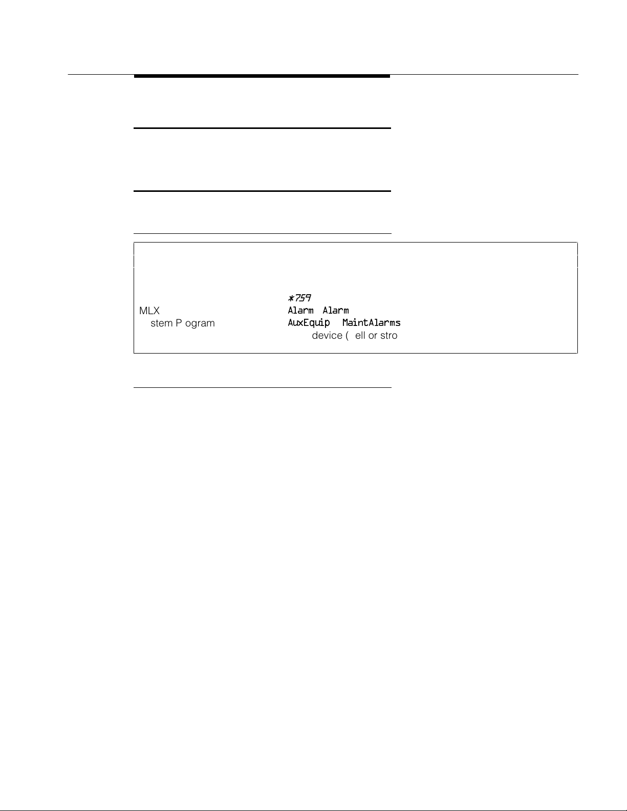
Programming Code
MLX Display Label
System Programming
Hardware Alert device (bell or strobe) for Maintenance Alert
*759
Alarm [Alarm
AuxEquip→MaintAlarms
]
Description
Alarms provide either a visible or audible indication when the system detects a
problem that needs immediate attention.
■
Alarm Button. A programmed button on Direct-Line Consoles (DLCs)
and a factory-set button on Queued Call Consoles (QCCs). It alerts the
operator to problems detected by the system software. The red LED next
to the Alarm button on the operator console turns on when the system
detects a problem (such as a problem with one of the trunks or some
other system error) that requires immediate attention. It remains on until
the problem is corrected.
■
Maintenance Alert. An alert device such as a bell or strobe light
connected to the line or trunk designated as a maintenance alarm jack.
The device rings or lights when the system detects a problem that
requires immediate attention.
■
The red LED on the processor module turns on when the system detects
a problem that requires immediate attention. It remains lit until the
problem is corrected.
■
The red LED on certain modules turns on when the system detects a
module-related problem, for example, a loss-of-service alarm on the
100D module.
Administration
29
Page 30

Feature Reference
Considerations and Constraints
As soon as the system detects a problem, the red LED next to the Alarm button
turns on and/or the maintenance alert sounds or flashes.
All system operator consoles with an Alarm button receive the indication.
Telephone Differences
Alarm buttons can be programmed only on system operator consoles.
Direct-Line Consoles
An Alarm button is factory-assigned on an analog DLC but not on an MLX DLC.
An operator at an MLX DLC can use the Inspect feature to display the number
of alarms; an analog DLC operator cannot use Inspect.
On a system with fewer than 29 lines, an Alarm button is factory-assigned to
analog DLCs with 34 or more buttons.
On a system with more than 29 lines, Alarm is replaced with line 30. The Alarm
button is not a fixed feature and can be assigned to any available button on an
analog or MLX DLC.
Queued Call Consoles
Alarm buttons can be programmed only on system operator consoles.
An Alarm button is a fixed feature on a QCC.
A QCC operator can use the Inspect feature to display the number of alarms.
Feature Interactions
Automatic
Maintenance Busy
Inspect Inspect can be used on an MLX DLC or a QCC to display the number of
Personal Lines A line or trunk jack used for a maintenance alarm cannot be assigned
Pools A trunk jack used for a maintenance alarm cannot be assigned to a
The red LED turns on next to the Alarm button on system operator
consoles, and the designated maintenance alert device sounds or
flashes when more than 50 percent of the trunks in the trunk pool are in
a maintenance-busy state.
alarms. Inspect cannot be used on an analog DLC.
as a personal line.
trunk pool (Hybrid/PBX mode only).
30 Alarm
Page 31

Feature Reference
Alarm Clock
At a Glance
Users Affected Users, Operators
Reports Affected None
Mode All
Telephones MLX display and analog multiline telephones
MLX Display Label
Description
If you have a display phone, you can use your phone as an alarm clock and set
it to beep at a particular time to remind you of an appointment, meeting, or other
important event. Until canceled, the alarm sounds every day at the set time.
Each MLX telephone and analog multiline display telephone has a timer to time
calls, meetings, breaks, or other events. When activated, the timer appears at
the top of the display, next to the date, and starts counting. It counts to 59
minutes and 59 seconds, then resets to zero and continues counting.
AlarmClk [Alarm
]
To Set the Alarm
To set the alarm on an MLX display telephone, follow the procedure below:
1. Press the Menu button.
2. Select
3. For English-language operation, dial a 4-digit time from 0100 to 1259 and
4. Select
5. Press the Home button. A bell appears on the Home screen.
Alarm Clock [AlClk
More button. The display shows the alarm status (On/Off) and the time
set.
select
a.m./p.m
French- or Spanish-language operation, dial a 4-digit time from 0000 to
2359. If you make an error, select
On
. to switch the display from A.M. to P.M. or back again. For
.
]. If this feature is not displayed, press the
Reset
and redial.
Alarm Clock
31
Page 32

Feature Reference
To set the alarm on an analog multiline telephone, follow the procedure below:
1. Press the Set button.
2. Press the Fwd button.
3. Press Set.
4. Press Fwd or Rev until the setting you want appears on the display.
5. Press Set.
6. Press Fwd or Rev until the setting you want appears on the display.
7. Press the Exit button. A bell appears on the display next to the date.
To Cancel the Alarm
To cancel the alarm on an MLX display telephone, follow the procedure below:
1. Press the Menu button.
2. Select
More button.
3. Select
4. Press the Home button. The bell disappears from the Home screen.
To cancel the alarm on an analog multiline telephone, follow the procedure
below:
ALARM Off
ALARM On
Hour
and
am/pm
Minutes
Alarm Clock [AlClk
Off
.
begins to flash
begins to flash.
begins to flash.
begin to flash.
.
]. If this feature is not displayed, press the
1. Press the Set button.
2. Press the Fwd button.
ALARM On
ALARM Off
begins to flash.
begins to flash.
3. Press the Exit button. The bell disappears from the display.
32 Alarm Clock
Page 33

Feature Reference
Allowed/Disallowed Lists
At a Glance
Users Affected
Reports Affected
Telephone users, operators
Access to Allowed Lists
Access to Disallowed Lists
Allowed Lists
Disallowed Lists
Remote Access (DISA) Information
Mode
Telephones
All
All
System Programming Establish, change, or remove Allowed/Disallowed Lists:
•
Tables→AllowList/Disallow
Assign or remove Allowed/Disallowed Lists for individual
telephones:
•
Tables→AllowTo/DisallowTo
Assign or remove Allowed/Disallowed Lists for non-tie trunks
used for Remote Access:
•
LinesTrunks→RemoteAccss→Non-TIE Lines
Allow List/DisallowLst
→
Assign or remove Allowed/Disallowed Lists for tie trunks used
for Remote Access:
•
LinesTrunks→RemoteAccss→TIE Lines
Allow List/DisallowLst
→
Assign or remove Allowed/Disallowed Lists for each remote
access barrier code:
•
LineTrunks→RemoteAccss→Barrier Code
Allow List/DisallowLst
Maximums
Allowed Lists 6 digits for each number (+ leading 1, if required)
10 numbers for each list (Release 3.1 and later systems may
also have Asterisk (*) or star preceding a leading star
codes)
8 lists for each system
8 lists for each telephone
Disallowed Lists 11 digits for each number (+ wildcard)
10 numbers for each list (Release 3.1 and later systems may
also have Asterisk (*) or star preceding a leading star
codes)
8 lists for each system
8 lists for each telephone
Allowed/Disallowed Lists 33
→
Page 34

Feature Reference
At a Glance - Continued
Factory Settings
Second Dial Tone Timer 0 ms (range: 0-5000 ms, increments of 200, entries rounded
down if not increments of 200.)
Default Disallowed List Disallowed List 7
Entries 0, 10, 11, 1809, 1700, 1900, 976, 1
Assigned to all VMI ports
ppp
976, * (p=any digit)
Description
Used in conjunction with calling restrictions (outward and toll), an Allowed List is
a list of numbers that the caller is allowed to dial, despite restrictions. For
example, an Allowed List assigned to an outward-restricted extension can allow
calls to specific local numbers, such as emergency (911) or toll numbers. For
toll-restricted extensions, an assigned Allowed List can allow calls to specific
area codes and/or exchanges needed for daily tasks.
A Disallowed List is a list of local or toll numbers that the telephone user is not
allowed to dial, even if the extension is otherwise unrestricted. Disallowed Lists
can be used as an alternative to or in conjunction with calling restrictions.
Both Allowed Lists and Disallowed Lists are assigned to individual extensions.
Allowed and Disallowed Lists can also be used in conjunction with Remote
Access to restrict calls made through the system from remote locations. In this
case, Allowed and Disallowed Lists can be assigned to either specific remote
access barrier codes or (if barrier codes are not used) to specific types of
trunks (all tie/DID and all non-tie/non-DID trunks).
When an Allowed List is assigned to a barrier code or remote access trunks, the
remote access user using that code can dial specific numbers included in the
list. When a Disallowed List is assigned to a barrier code, the remote access
user using that code cannot reach the specific numbers included in the list.
If barrier codes are not used for remote access, then Allowed and Disallowed
Lists for remote access users can be assigned to all tie/DID trunks and all
non-tie/non-DID trunks.
A Night Service Allowed List can be programmed with up to 10 numbers that
anyone can dial without having to enter a Night Service password. For
additional information, see “Night Service.”
34 Allowed/Disallowed Lists
Page 35

Feature Reference
Star Codes and Allowed/Disallowed Lists
In some instances, after dialing a
three digit number) the central office provides a second dial tone as a prompt
for the dialer to enter more digits. In most cases this second dial tone is
immediate. However, in cases when the second dial tone is delayed, calls can
be misrouted or dishonest users might be able to circumvent communications
system dialing restrictions.
In Release 3.1 and later, the system administrator can enter the star digit (*) in
Allowed List and Disallowed List entries. The communications system can be
programmed with a delay period (Second Dial Tone Timer) during which no
dialing is allowed (in order to let the central office dial tone return). If dialing is
attempted, the call is treated as though it had violated calling restrictions and is
not completed.
The star codes that are recognized by the system are as follows:
■
2-digit codes: *(00-19,40-99)
■
3-digit codes: *(200-399)
star code
(a star digit followed by a two or
Restrictions are reset after leading star codes. This means that any star codes
that are not included in an Allowed or Disallowed List are not considered. The
digits that follow the star code are then compared again to the lists. If a caller
dials *67280, Allowed/Disallowed Lists acts as if 280 were dialed. Star codes do
not need to be placed into an Allowed or Disallowed List in this case to restrict
calls to specific exchanges or Area Codes.
The programmed delay is also activated when the rotary telephone equivalent of
star codes is dialed (for example, 1170). Multiple leading star codes (such as
*67*70) are also handled by the system, since the dialed number is checked
against Allowed and Disallowed Lists after each star code is detected.
Following are examples of how to set table entries to achieve specific results:
■
Disallow calls preceded by *67, but allow all other calls: Enter *67 as a
Disallowed List entry.
■
Disallow calls preceded by all star codes, but allow all other calls: Enter *
as a Disallowed List entry.
■
Disallow calls preceded by *67, or by *69 but allow all other calls: Enter
*67 as a Disallowed List entry and enter *69 as a separate entry.
■
Disallow calls preceded by *67, calls to 900 numbers and 411 but allow
all other calls: Enter *67, 900, and 411 as separate Disallowed List
entries.
Allowed/Disallowed Lists
35
Page 36

Feature Reference
Following are examples of specific results that cannot be achieved through
programming MERLIN LEGEND:
■
Disallow *67 when dialing a specific exchange.
■
Disallow *67 only when it is followed by *69.
Default Disallowed List
In Release 3.1 and later, a default Disallowed List (list 7) is defined which
includes the following entries:
(
p
=any digit). This list is automatically assigned to any port programmed as a
VMI port.
!
Security Alert:
The system manager should assign this list to any extension that
does not need access to the numbers in the list.
The system manager should assign this list to any extension that does not need
access to the numbers in the list.
0, 10, 11, 1809, 1700, 1900, 976, 1
ppp
976, *
,
Disallowed Lists and VMI ports
In Release 3.1 and later, ports assigned as Generic VMI or Integrated VMI are
assigned the default Disallowed List.
If the system manager wants to allow access to the voice messaging system
Outcalling feature, any entries in the default Disallowed List apply to Outcalling
calls.
!
Security Alert:
Any changes to the default Disallowed List entries and other
restrictions must be considered carefully in order to minimize the
potential for toll fraud.
If the system manager changes a port to a non-VMI port, the default Disallowed
List is not removed from the port. If the default Disallowed List should be
removed, the system manager must remove it from the port thorough system
programming.
Considerations and Constraints
A Disallowed List takes precedence over an Allowed List. If a telephone number
is on both an Allowed List and a Disallowed List assigned to an individual
extension, the caller cannot complete a call to that number.
36 Allowed/Disallowed Lists
Page 37

Feature Reference
If a zero (0) is programmed as the first digit of an Allowed List entry, any toll
restriction assigned to an extension is removed for calls placed through a toll
operator.
Individual Allowed and Disallowed Lists are numbered 0 through 7. Within each
list, there are 10 entries numbered 0 through 9.
The Pause character (entered by pressing the Hold button) can be used as a
wild card character in Disallowed Lists, for example, to indicate that calls to a
given exchange are restricted in every area code. (The Pause character is
shown on the planning form as
Allowed List entries. The Pause character does not act as a wild card for the
character.
When used in conjunction with Remote Access, Allowed and Disallowed Lists
are assigned to specific barrier codes or to types of trunks: all tie/DID trunks, or
all non-tie/DID trunks. Allowed and Disallowed Lists cannot be assigned to
trunks on an individual basis.
When used with Automatic Route Selection (ARS), Allowed and Disallowed Lists
are not applied until the caller dials the ARS code and a pool is selected.
p.) Wild card characters are not permitted in
*
Because restrictions imposed by a Disallowed List apply to the extension used
to initiate a call to an outside number, a user with a restricted extension can
circumvent restrictions by asking an operator with an unrestricted console to
connect an outside call.
Feature Interactions
Auto Dial A user with a restricted extension cannot dial a restricted number
(outside or toll) by using an Auto Dial button, unless the number is on
the Allowed List for that extension. A user cannot dial an outside
number by using an Auto Dial button if the number is on a Disallowed
List.
Automatic Route
Selection
Calling Restrictions When used with calling restrictions, Allowed Lists can permit the dialing
Automatic Route Selection (ARS) checks Allowed and Disallowed Lists
before choosing the route for a call. This prevents users with restricted
extensions from dialing numbers that are not on an Allowed List. ARS
also prevents a user from dialing numbers on a Disallowed List.
of specific numbers, such as emergency numbers, from an outward- or
toll-restricted extension.
Allowed/Disallowed Lists
37
Page 38

Feature Reference
Conference A user with a restricted extension cannot add a participant (outside or
toll) to a conference call unless the participant’s number is on the
Allowed List for that extension.
A user cannot add an outside number to a conference call if the number
is on a Disallowed List.
Directories A user with a restricted extension cannot use the System Directory to
dial a restricted number unless the System Speed Dial number is
marked or the number is on the Allowed List for that extension.
Forward and
Follow Me
Night Service A Night Service Emergency Allowed List can be programmed with up to
Personal Lines A user with a restricted extension cannot dial a restricted number
Remote Access Both Allowed and Disallowed Lists are assigned as items of the class of
Speed Dial When a marked System Speed Dial number (the dialed number is
A user with a restricted extension cannot forward calls to a restricted
(outside or toll) number unless the number is on the Allowed List for that
extension. If the number is on the Disallowed List for that extension, the
call cannot be forwarded. When activating Forward, a user with a
restricted extension does not hear an error tone, but when a call is
received, the Forward is denied if the number is not on the Allowed List.
10 numbers that any user can dial without having to enter the Night
Service password. For additional information, see “Night Service.”
(outside or toll) on a personal line button unless the number is on the
Allowed List for that extension. If the number is on a Disallowed List, the
user cannot dial it.
restriction (COR) for the Remote Access feature. When barrier codes
are not used, Allowed and Disallowed Lists are assigned to trunks
systemwide. When barrier codes are used, Allowed and Disallowed
Lists are assigned to individual barrier codes.
suppressed from the display) is used to dial a number, calling
restrictions (such as toll or outward restrictions, or Allowed and
Disallowed Lists) assigned to that extension are overridden. When an
unmarked System Speed Dial or a Personal Speed Dial number is used
to dial a restricted number, the call cannot be completed unless the
number is on the Allowed List for that extension.
Toll Type When trunks with different toll types are connected (for example, basic
trunks and PRI facilities), people must dial a toll prefix (
calls on some trunks, but it is not required on other trunks. In such
instances, two Disallowed List entries are needed to restrict users from
dialing specific area codes and/or telephone numbers. For example, to
restrict users from dialing area code 505, the Disallowed List must
include both 505 and 1505.
0
or 1) for toll
38 Allowed/Disallowed Lists
Page 39

Feature Reference
home extension
in SMDR Report:
11) (0-9,*)
Authorization Code
At a Glance
Users Affected Telephone users
Reports Affected Extension Information, Authorization Code Information, SMDR
Mode All
Telephones All (touch-tone telephones except QCC)
Programming Code
Feature Code
MLX Display Label
System Programming
*80
80
Auth Code [Auth
Assign or remove Authorization Code for a telephone:
•
Extension
]
→More→
Auth Code→Enter
Assign “
•
Options→SMDR→Auth Code→Home Extension Number
Assign actual authorization code in SMDR Report:
•
Options→SMDR→Auth Code→Authorization Code
To print a report on all authorization codes on a system:
• More
Maximums
Number of Digits in
authorization code
Factory Settings
SMDR Report Home Extension Number
Authorization codes Not assigned to any extensions
11 (Range 2–
→
Print→Auth Code
Description
The Authorization Code feature allows you to pick up someone else’s telephone,
enter your authorization code, and complete a call with the restrictions that
apply to your own telephone (
outward restriction, Facility Restriction Level (FRL), Allowed Lists, Disallowed
Lists, Forced Account Code Entry (FACE), Night Service Exclusion List, and Dial
Access to Pools. All other functions on the telephone are those of the extension
you are using, not your home extension.
home extension
”
). This includes toll restrictions,
Each entry of an authorization code provides restriction privileges for a single
phone call. If you put the first call on hold and start to make an outside call, the
Authorization Code button’s green LED goes off. If you wish to make another
call, you must reactivate the Authorization Code feature in order to obtain the
restriction privileges of the home extension.
Authorization Code
39
Page 40

Feature Reference
home
or the authorization code is stored in the ACCOUNT field when no
Authorization codes can also be used for call control and call accounting
through the SMDR printout. SMDR may be programmed so that the “
extension”
account code is entered. The factory setting is for the home extension to be
stored in the ACCOUNT field.
An authorization code can range from 2 to 11 characters and must be unique
across the system. However, more than one user can use an authorization code
simultaneously. Authorization codes do not all have to be one length
systemwide.
Through system programming, the system manager can assign one
authorization code for each telephone extension. One Authorization Code
button can be programmed on any MLX or analog multiline telephone (except
QCCs). A button with a green LED is suggested.
If a user does not have a physical telephone, a phantom extension may be
programmed as a “home extension” to allow the user to use restricted
telephones and for call control and call accounting purposes.
The Authorization Code feature can be activated by modems and fax machines
as well by dialing
#80
and then entering the authorization code followed by a #.
Activation of Authorization Code
You can pick up any telephone (except a QCC) in the system and use an
authorization code. You obtain home extension calling privileges by entering
your home extension’s authorization code. Do this in one of the following ways:
■
Press a programmed Authorization Code button and then enter the
assigned authorization code.
■
Press the Feature button on an MLX display telephone and then select
Auth Code
■
Press the Feature button on an MLX telephone or analog multiline
telephone and dial
■
Press
If you activate the feature while on-hook, the features select an SA/ICOM button
and turns on the speakerphone, if present.
After you activate the feature, the green LED (if present) next to a programmed
Authorization Code button starts to flash slowly to indicate that you may enter
the code’s digits. An MLX display telephone shows
multiline display telephone shows
.
#80
while off-hook on an SA/ICOM button.
80
.
Auth:
and an analog
Auth?
.
40 Authorization Code
Page 41

Feature Reference
Entering Authorization Code
While you enter the assigned authorization code, you hear internal dial tone. If
you do not enter the code within 15 seconds, the feature is deactivated.
If a telephone with a display is used, the display shows asterisks instead of the
entered digits.
To complete entry of the authorization code, either press a programmed
Authorization Code button again, or dial a # to signify the end of the code. If the
entered authorization code matches an assigned code, you continue to hear
internal dial tone and can start dialing the telephone number.
The green LED associated with a programmed Authorization Code button
becomes steady to indicate that an authorization code has been successfully
entered. The LED remains steady as long as the Authorization Code feature
remains active.
If the authorization code is not valid, you hear an error tone (a high tone
followed by a low tone). The green LED associated with a programmed
Authorization Code button goes off to indicate that the Authorization Code
feature is not active. An MLX display telephone shows the message
Not Valid,
and an analog multiline display telephone shows the message
Auth Code
Error
.
Deactivation of Authorization Code
Each entry of an authorization code is good for only one phone call. After
completing a call, the current extension loses “home extension” privileges. It
also loses privileges for subsequent calls after putting a call on Hold, or after
initiating Recall, Headset Hang Up, or Park features. If a far-end disconnect is
not received from the central office, you must go on-hook or select another
outside line to deactivate the Authorization Code feature.
After the feature is deactivated, the green light next to the Authorization Code
button (if present) turns off.
Considerations and Constraints
An authorization code can only be entered while hearing internal dial tone.
Incoming calls are not affected by an authorization code.
There is no limit to the number of users who can use the same authorization
code simultaneously.
Authorization codes cannot contain a
An authorization code must be no fewer than 2 and no more than 11 digits long.
An authorization code must be unique across the system.
#
nor begin with a *.
Authorization Code
41
Page 42

Feature Reference
Telephone Differences
Queued Call Console
The Authorization Code feature cannot be activated on a QCC.
Analog Multiline Telephones
At an analog multiline telephone with a General Purpose Adapter connected to it
and set for Auto operation, you must lift the handset before activating
Authorization Code. Do not use the Spkrphone button.
Single-Line Telephones
On single-line telephones, entry of an authorization code is activated by dialing
#80
. The entry is completed by dialing #. Single-line telephones must have
touch-tone dialing and must be programmed through Idle Line Preference
(using centralized telephone programming) to select an SA/ICOM button when
the user picks up the handset or activates the speakerphone.
On a single-line telephone, an authorization code must be entered before
accessing an outside line.
Single-line telephone users cannot enter authorization codes by using a System
Speed Dial or Personal Speed Dial code because these features are activated
by dialing
it cannot also be used to activate the speed dial features.
#
. Pressing # completes the entry of an authorization code, therefore,
Feature Interactions
Account Code Entry If an account code is not entered, the ACCOUNT field of the SMDR
printout contains the authorization code or the “home extension” used to
obtain restriction privileges. If an account code is entered at any time
during a call, the account code is stored in the SMDR record.
If the extension used to make a call is assigned Forced Account Code
Entry, the caller is not forced to enter the account code while using the
Authorization Code feature.
If the home extension is assigned Forced Account Code Entry, the
caller must enter an account code after (or before) entering an
authorization code.
Automatic Route
Selection
Conference You must enter an authorization code before each outside call for a
An authorization code must be entered before making dialing the ARS
access code.
conference.
You may enter a different authorization code for different outside calls.
This may be useful if different restriction privileges are required for
different outside calls for the conference.
42 Authorization Code
Page 43

Feature Reference
Headsets Pressing the Headset Hang Up button deactivates the Authorization
Code feature.
Hold Initiating Hold after entering an authorization code deactivates the
Authorization Code feature for subsequent calls.
Last Number Dial For security, the authorization code is not saved by the Last Number
Dial feature.
Authorization Code does not affect Last Number Dial on the extension
you are using or on your home extension. You can retrieve the last
number dialed on the phone you are using.
Night Service An authorization code can be used when Night Service is activated.
Park Initiating Park after entering an authorization code deactivates the
Authorization Code feature. An authorization code does not need to be
entered to pick up a parked call.
Remote Access A caller cannot enter an authorization code on a remote access call.
Saved Number Dial For security, the authorization code is not saved by the Saved Number
Dial feature.
Authorization Code does not affect Saved Number Dial on the extension
you are using or your home extension. You can retrieve the saved
number on the phone you are using.
SMDR All outgoing calls over the minimum call length made using an
authorization code are recorded in the SMDR record.
If an account code is not entered, the ACCOUNT field of the SMDR
printout contains the authorization code used to obtain restriction
privileges or the home extension number, depending on how SMDR is
programmed. If an account code is entered at any time during a call,
the account code is stored in the SMDR record instead.
Speed Dial Users cannot enter authorization codes by using a System Speed Dial
or Personal Speed Dial code because these features are activated by
dialing
cannot also be used to activate the speed dial features.
System
Renumbering
Transfer If the user wants to transfer a call to an outside number, the
If extensions are renumbered, authorization codes remain with the
logical IDs where they were originally assigned. System Renumbering
also removes all phantom extensions and their authorization codes.
authorization code must be entered to obtain “home extension”
privileges at the beginning of the transfer. In this case, One-Touch
Transfer does not work.
#
. Pressing # completes the entry of an authorization code and
Authorization Code
43
Page 44

Feature Reference
Auto Answer All
At a Glance
Users Affected Telephone users, DLC operators
Reports Affected Extension Information
Mode All
Telephones Analog multiline
Programming Code
MLX Display Label
Hardware General Purpose Adapter (GPA) needed to connect
Description
Auto Answer All is used on analog multiline telephones only or analog
Direct-Line Consoles (DLCs) with a modem, answering machine, or other
answering device connected through a General Purpose Adapter (GPA) to
answer both inside and outside calls when the user is not available.
*754
AutoAns All
answering device to analog multiline telephone; 502C
headset adapter needed for headset options.
(in centralized telephone programming)
To activate Auto Answer All, slide the switch on the GPA to Auto and press the
Auto Answer All button. The green LED next to the button turns on, and
incoming calls are answered automatically.
To deactivate the feature, either slide the switch on the GPA to Basic or press
the Auto Answer All button. If the button is pressed to deactivate the feature, the
green LED next to the button turns off. In either case, the telephone returns to
normal operation.
Auto Answer All can also be used with a headset adapter to allow an analog
multiline telephone user or analog DLC operator with a headset to be connected
automatically to ringing calls. A tone heard through the headset signals an
incoming call.
A programmed button activates and deactivates Auto Answer All. Select the
lines to be answered by the device by programming Immediate Ring or Delay
Ring as the ringing option. Lines that are not to be answered should be
programmed as No Ring.
44 Auto Answer All
Page 45

Feature Reference
Telephone Differences
Queued Call Consoles
Auto Answer All cannot be used on a QCC.
Other Multiline Telephones
Auto Answer All cannot be used on MLX telephones, cordless telephones, or
wireless telephones.
Single-Line Telephones
Auto Answer All cannot be used on single-line telephones. This includes
single-line telephones with speakerphones.
Considerations and Constraints
When Auto Answer All is used, all voice announcements (including Voice
Announce to Busy) should be disabled because the device connected to the
GPA cannot answer voice-announced calls.
Auto Answer All cannot be used with a Hands-Free Unit (HFU).
Occasionally a second alert (or zip) tone may sound on incoming or intercom
calls. This is normal.
Auto Answer All should be used instead of Auto Answer Intercom to allow an
answering device to answer intercom calls. Auto Answer Intercom can cause
intercom calls to be dropped.
Feature Interactions
Auto Answer
Intercom
Auto Dial At an analog multiline telephone with a General Purpose Adapter (GPA)
Coverage Auto Answer All is used when a receiver with an analog multiline
Forward and
Follow Me
Both Auto Answer All and Auto Answer Intercom can be programmed
on the same extension, but they cannot be used at the same time. Auto
Answer Intercom should not be used with answering devices.
connected to it and set for Auto operation, you must lift the handset
before pressing an Auto Dial button. Do not use the Spkrphone button.
telephone wants Individual or Group Coverage calls answered by an
answering machine connected to the extension.
An answering device connected to an analog multiline telephone can
answer forwarded calls when Auto Answer All is activated.
Auto Answer All
45
Page 46

Feature Reference
Group Calling Members in a calling group with analog multiline telephones can use
Auto Answer All when answering machines are connected to their
extensions. When the feature is activated, all incoming calls ringing on
the calling group member’s extension—both calls for the calling group
and calls to the member’s own extension—are answered automatically
by the answering machine.
Ringing Options An analog multiline telephone user selects the lines to be answered by
programming them for Immediate or Delay Ring and selects the lines
not to be answered by programming them for No Ring. If the device is
to answer only inside calls, all personal lines (outside lines assigned to
buttons on the telephone) must be programmed for No Ring.
System
Access/Intercom
Buttons
Voice Announce Voice-announced calls received at an analog multiline telephone are
When Auto Answer All is activated, all calls received at an SA Ring,
ICOM Ring, SA Voice, or ICOM Voice button can be answered
automatically by the device connected to the GPA. If Shared SA
buttons are assigned, only the principal extension should be
programmed for Immediate Ring to prevent the call from being
answered at the principal extension and at extensions with the Shared
SA button.
not answered by a device connected through a GPA, because ringing
current is not sent to the device.
46 Auto Answer All
Page 47

Feature Reference
Auto Answer Intercom
At a Glance
Users Affected Telephone users, operators
Reports Affected Extension Information
Mode All
Telephones Analog multiline
Programming Code
MLX Display Label
Hardware Hands-Free Unit (HFU) is used to answer inside calls.
Description
MLX telephones can automatically answer calls on their speakerphones if the
Hands-Free Answer on Intercom button (HFAI) is activated. Some older models
of analog multiline telephones do not have built-in speakerphones. People with
these telephones can still answer inside calls without lifting the handset by
using Auto Answer Intercom with an optional Hands-Free Unit (HFU).
*753
AutoAnsIcom
(in centralized telephone programming)
To activate Auto Answer Intercom, press the Auto Answer Intercom button. The
green LED next to the button turns on. The HFU turns on automatically when an
inside call is received.
To deactivate the feature, press the Auto Answer Intercom button again. The
green LED turns off, and the HFU does not automatically turn on when an
intercom call is received.
Mode Differences
When Auto Answer Intercom is activated in Hybrid/PBX mode and a call is
received on an SA button, the HFU turns on, even if the button is programmed
for Delay Ring or No Ring.
Telephone Differences
Queued Call Consoles
Auto Answer Intercom cannot be used on a QCC.
Auto Answer Intercom
47
Page 48

Feature Reference
Other Multiline Telephones
Auto Answer Intercom cannot be used on MLX telephones, cordless
telephones, or wireless telephones.
Single-Line Telephones
The Auto Answer Intercom feature cannot be used on single-line telephones.
This includes single-line telephones with speakerphones.
Some single-line telephones (such as the 8110) have their own telephone based
Auto Answer feature, which can be used with a Release 4.0 or later MERLIN
LEGEND Communications System.
Considerations and Constraints
Auto Answer All should be used instead of Auto Answer Intercom to allow an
answering device to answer intercom calls. Auto Answer Intercom can cause
intercom calls to be dropped.
When Auto Answer Intercom is activated in Hybrid/PBX mode and a call is
received on an SA button, the HFU turns on, even if the button is programmed
for Delay Ring or No Ring.
Feature Interactions
Auto Answer All
Coverage
System Access/
Intercom Buttons
Both Auto Answer All and Auto Answer Intercom can be programmed
on the same telephone, but they cannot be used at the same time.
Auto Answer Intercom does not allow a receiver with an analog multiline
telephone to use an HFU to answer calls received on a Primary Cover,
Secondary Cover, or Group Cover button.
When Auto Answer Intercom is activated, the Hands-Free Unit (HFU)
answers inside calls received on an SA button. The HFU does not
answer calls on a Shared SA button.
48 Auto Answer Intercom
Page 49

Feature Reference
Auto Dial
At a Glance
Users Affected Telephone users, DLC operators
Reports Affected Extension Information
Mode All
Telephones All except QCC and single-line telephones
Programming Codes
*22
+
Inside
Outside
MLX Display Labels
Maximums 28 digits, including special characters
!
CAUTION:
Emergency numbers and other numbers should be tested during off-peak
hours, such as early morning or late evening. The user should remain on
the line and briefly explain to the dispatcher the reason for the call.
ext. no.
*21
+
number
Auto Dial, Inside [AutoD,In
Auto Dial, Outside [AutoD,Out
]
]
Description
Use Auto Dial buttons for one-touch dialing of frequently called telephone
numbers. Two types of Auto Dial buttons can be programmed:
■
Inside Auto Dial. This button automatically dials any extension or group
extension in the system such as a co-worker, calling group, fax machine,
or voice mail system. An operator can also program inside Auto Dial
buttons for park zone extension numbers.
When an inside Auto Dial button is programmed, the user can see the
status of the extension associated with the button; the green LED next to
the button is on when a person at the extension is on a call, when Do Not
Disturb is on, or when the extension is forced idle for centralized
telephone programming or system programming.
■
Outside Auto Dial. This button automatically dials frequently called
telephone numbers, as well as account codes, long distance company
access codes, bank access codes, or emergency contact numbers.
Considerations and Constraints
When an Auto Dial button is used to make a call, the green LED next to the
button does not turn on.
Only company extension numbers should be programmed on inside Auto Dial
buttons. Account codes, long-distance company access codes, and outside
telephone numbers should be programmed on outside Auto Dial buttons.
Auto Dial
49
Page 50

Feature Reference
If a user tries to program an incomplete extension number on an inside Auto
Dial button, the system provides an error tone and the button remains as
programmed.
If numbers are dialed incorrectly by outside Auto Dial, it is possible that the
digits are being dialed before a central office dial tone is received. In this case,
a Pause should be programmed as the first digit of the dialed number in Key
mode and the next digit (after the dial-out code) of the dialed number in
Hybrid/PBX mode.
To enter special characters in a telephone number programmed on an outside
Auto Dial button, use Conf for the Flash character, Drop for the Stop character,
and Hold for the Pause character. See Table 1. These special characters can
not be programmed on inside Auto Dial buttons.
If the Stop character is the last character in the number, it has no effect on how
the Auto Dial button functions.
In Release 2.1 and later, when a call is forwarded to a multiline telephone that
has an inside Auto Dial button programmed for the forwarding telephone, the
green light next to the Auto Dial button does not flash.
Table 1. Special Characters for Outside Auto Dial
Press See* Means
†
Drop
s
Stop. Halts dialing within a sequence of automatically dialed numbers. For
example, an outside Auto Dial button may be programmed with a
password, then a Stop, followed by a telephone number. To use Auto Dial
with a Stop in the sequence, press the button to dial the password, listen
for the dialing and connection, and press the button again to dial the
telephone number.
Hold
p
Pause. Inserts a 1.5-second pause in the dialing sequence. Multiple
consecutive pauses are allowed.
†
Conf
f
Flash. Sends a switchhook flash. Must be the first entry in the dialing
sequence.
##
#
End of Dialing (for extension programming only). Use at the end of a
dialing sequence to indicate that you have finished dialing or to separate
one group of dialed digits from another, such as account code and
number dialed.
#
#
End of Dialing. Use at the end of a dialing sequence to indicate that you
have finished dialing or to separate one group of dialed digits from
another.
* Display phones only.
†
Not available on MLC-5 cordless phones.
50 Auto Dial
Page 51

Feature Reference
Mode Differences
Hybrid/PBX Mode
In Hybrid/PBX mode, the system automatically turns on the speakerphone and
selects an SA button when you press an inside or outside Auto Dial button
before lifting the handset.
Key Mode
In Key mode, the system automatically turns on the speakerphone and selects
an outside line button when you press an outside Auto Dial button without lifting
the handset. When you press an inside Auto Dial button without lifting the
handset, the system automatically turns on the speakerphone and selects an
ICOM button.
Behind Switch Mode
In Behind Switch mode, the system automatically selects the prime line button
and turns on the speakerphone whenever the user presses an outside Auto Dial
button. If the Automatic Line Selection sequence has been changed to select
the ICOM button, press the prime line or outside line button before pressing an
outside Auto Dial button. Pressing an inside Auto Dial button without lifting the
handset causes the system to automatically turn on the speakerphone and
select an ICOM button. The system does not automatically select an outside
line.
Telephone Differences
Direct-Line Consoles
Inside Auto Dial can be programmed onto available buttons on a DLC. Use the
buttons to transfer a call, make an inside call, or determine availability of the
extension.
Queued Call Consoles
Use the Personal or System Directory instead of outside Auto Dial buttons,
which cannot be programmed on the Queued Call Console (QCC). The
Extension Directory or DSS buttons can be used instead of inside Auto Dial
buttons.
Auto Dial
51
Page 52

Feature Reference
Other Multiline Telephones
All multiline telephone users can program and use Auto Dial buttons. When
using an MLX-20L telephone, use Personal Directory in place of Auto Dial. On
an MLX display telephone, select the feature from the display to program it.
At an analog multiline telephone with a General Purpose Adapter (GPA)
connected to it and set for Auto operation, you must lift the handset before
pressing an Auto Dial button. Do not use the Spkrphone button.
Single-Line Telephones
Single-line telephone users cannot program Auto Dial buttons.
Feature Interactions
Account Code Entry You can program frequently used account code numbers onto outside
Auto Dial buttons.
Allowed Lists
Calling Restrictions
Automatic Route
Selection
Conference Press the Conf button to enter the Flash special character in a
Digital Data Calls A terminal adapter can make a call using an auto dial button, by dialing
Disallowed Lists You cannot dial an outside number using an Auto Dial button when the
Display When you press a programmed Auto Dial button, the digits appear on
Do Not Disturb When you activate Do Not Disturb, the green LED turns on next to all
Forced Account
Code Entry
A user with a restricted extension cannot dial a restricted number
(outward or toll) using an Auto Dial button, unless the number is on the
Allowed List for that extension.
You cannot program Automatic Route Selection (ARS) dial-out codes on
inside Auto Dial buttons. You can program an ARS dial-out code on an
outside Auto Dial button.
telephone number programmed on an outside Auto Dial button. Press
the Drop button to enter the Stop special character in a telephone
number programmed on an outside Auto Dial button.
the virtual number of the auto dial button (for example #01).
number is on a Disallowed List assigned to the extension.
the display as if you were dialing them from the dialpad, and the
number is automatically dialed. An MLX telephone user can select
Dial
from the display only during programming.
inside Auto Dial buttons programmed with the your extension.
Frequently used account code numbers can be programmed onto
outside Auto Dial buttons.
Auto
Forward and
Follow Me
52 Auto Dial
When a call is forwarded to a multiline telephone that has an Auto Dial
button programmed for the forwarding telephone, the green light next to
the Auto Dial button does not flash.
Page 53

Feature Reference
not an inside one
Group Calling The Calls-In-Queue-Alarm button for a calling group is assigned on a
multiline telephone by programming an inside Auto Dial button with the
calling group’s extension number. When a DSS is not available, the
calling group supervisor uses Auto Dial buttons programmed with each
calling group member’s extension to monitor group member availability.
Headset Options If headset operation is activated on the telephone or console, select a
line button before using Auto Dial to dial an extension or an outside
number.
Last Number Dial A number you dial by pressing a programmed outside Auto Dial button
is saved for Last Number Dial as if you dialed it with the dialpad, but
special characters do not work. An extension dialed when you press a
programmed inside Auto Dial button is not saved for Last Number Dial.
Microphone Disable When an MLX telephone user’s microphone is disabled, pressing an
Auto Dial button turns on the speakerphone so the user can hear the
number being dialed. However, the user must lift the handset to talk
once the call is answered.
Paging You can program an extension for a speakerphone paging group on an
inside Auto Dial button.
Park An operator can program park zone codes on inside Auto Dial buttons.
An inside Auto Dial button can also be programmed with a user’s or
system operator’s own extension number and can be used to park calls.
When the system is programmed for One-Touch Hold with manual
completion, you hear a busy signal when parking a call at your own
extension number and must complete the transfer by hanging up or
pressing the Transfer button.
Personal Lines Only an outside Auto Dial button—
personal line.
Pools Pool dial-out codes cannot be programmed on inside Auto Dial buttons.
A pool dial-out code can be programmed on an outside Auto Dial
button when a telephone number is also included.
Saved Number Dial A number you dial by pressing a programmed outside Auto Dial button
can be saved for Saved Number Dial by pressing the programmed
Saved Number Dial button.
Signaling You cannot program a Signal button and an Auto Dial button for the
same extension. Attempting to program both types of buttons for one
extension causes the system to erase the button that was programmed
first.
SMDR All numbers dialed on an outside call using Auto Dial are recorded on
the SMDR report.
—can be used on a
Auto Dial
53
Page 54

Feature Reference
System
Access/Intercom
Buttons
Transfer You can press inside Auto Dial buttons instead of dialing extension
When you press an inside Auto Dial button, the system automatically
selects an SA or ICOM button and turns on the speakerphone. When
you press an outside Auto Dial button, the system automatically selects
an outside line button in Key mode, a prime line button in Behind Switch
mode, or an SA button in Hybrid/PBX mode.
numbers to transfer calls. To use the One-Touch Transfer option, you
must program inside Auto Dial buttons for extensions to which you
transfer calls. When an operator transfers a call and it returns
unanswered, the green LED next to the Auto Dial button flashes to
indicate the extension from which the call is returning. Only system
operators receive this indication.
54 Auto Dial
Page 55

Feature Reference
Automatic Line Selection and Ringing/Idle Line Preference
At a Glance
Users Affected Telephone users, operators
Reports Affected Extension Information
Mode All
Telephones All
Programming Codes
Ringing/Idle Line Preference
On
Off
ALS sequence (centralized telephone programming only for single-line telephones)
Begin button sequence
End button sequence
MLX Display Label
Maximums
Buttons for each telephone
in ALS sequence
Factory Settings
Ringing/Idle Line
Preference
*343
*344
*14
**14
Line Prefer [LnPrf
AutoLineSel
8
On
(centralized telephone programming only)
]
ALS Sequence by Mode
MLX Telephones
Analog Multiline
Telephones
Single-Line Telephones
Direct-Line Consoles
Queued Call Consoles
Description
Automatic Line Selection (ALS) and Ringing/Idle Line Preference are two closely
related features. Ringing/Idle Line Preference directs the system to
automatically select a line button for making or answering a call; ALS specifies
the order in which buttons should be selected.
Hybrid/PBX Key Behind Switch
3 SA 8 personal lines 1 prime line
3 SA 8 personal lines 1 prime line
3 SA 2 ICOM 1 prime line
2 SA + 8 personal lines 1 prime line +
6 personal lines 7 personal lines
5 Call (fixed)
Automatic Line Selection and Ringing/Idle Line Preference
55
Page 56

Feature Reference
Ringing/Idle Line Preference
Ringing/Idle Line Preference is a single option that controls two aspects of a
telephone’s behavior: selection of a line when a call arrives, and selection of a
line when a user goes off hook. Turn this option on or off for each extension
through extension programming or centralized telephone programming, using
the display or programming codes. When Ringing/Idle Line Preference is on for
an extension, the system selects a line button automatically, as follows:
■
Ringing Line Preference selects a ringing outside line, SA or ICOM
button, or Cover button; that is, the red LED turns on next to the button
with the ringing call. If you lift the handset or press the Speaker button,
you are automatically connected to the ringing call.
The button must be programmed for Immediate Ring or Delay Ring. The
red LED next to a button programmed for No Ring does not turn on
unless you press that button to select that line. See “Ringing Options” for
additional information.
■
Idle Line Preference selects an available outside line, SA, or ICOM button
for an outgoing call. If you lift the handset or press the Speaker button
when no call is ringing, the red LED turns on next to an available line
button, and you are automatically connected to that line.
On is the factory-setting for Ringing/Idle Line Preference for all extensions. If
Ringing/Idle Line Preference is turned off for an extension, no line button at that
extension is ever selected automatically. The red LED is never on until you
press the line button with a ringing call (flashing green LED) or an available line
button (green LED off) to make a call.
Automatic Line Selection
When Ringing/Idle Line Preference is turned on at an extension, the system
uses the programmed ALS sequence to select an idle SA or ICOM button or
outside line button for originating a call. When you lift the handset or press the
Speaker button without selecting a line button, the red LED next to the first
button in the programmed sequence turns on and you are connected to that
line. If the first line is busy, the system selects the second button in the
sequence, and so on.
For example, if you normally make toll calls, a WATS line assigned to the
extension can be programmed as the first line in the sequence, and local lines
as the second, third, and so on. When you lift the handset or press the Speaker
button, the WATS line, if available, is selected automatically.
On a multiline telephone you can override ALS by pressing the preferred line
button before you lift the handset or press Speaker (the red LED next to the
selected button turns on).
56 Automatic Line Selection and Ringing/Idle Line Preference
Page 57

Feature Reference
Up to eight line buttons (except on single-line telephones) can be programmed
in the ALS sequence for an extension, either through centralized telephone
programming or through extension programming, using programming codes
only.
IMPORTANT:
Your current Automatic Line Selection table is deleted immediately after you
press
*14
. There is no way to cancel the operation. You must program new
selections and then press
**14
to end the operation.
Table 2 shows the factory-set ALS sequence for each kind of telephone
according to system operating mode. When Ringing/Idle Line Preference is on,
buttons are selected in the numbered order shown. For multiline telephones
(including operator consoles), the factory-set sequence begins with the lower
left button of the type indicated, moves upward in the first column of buttons,
moves to the bottom of the next column to the right (if necessary), and finally
moves upward until the maximum of eight line buttons is included in the
sequence. Where outside line buttons are included in the sequence, they are
selected in numeric order (by default, 801, 802,…), up to the maximum number
of lines shown.
Table 2. Factory-Set Automatic Line Selection Sequence
Mode
Telephone Hybrid/PBX Key Behind Switch
Multiline (MLX
or Analog)
Single-Line 3. SA O
Direct-Line
Consoles
(MLX or
Analog)
Queued Call
Console
SA R, ICOM R = SA Ring, ICOM Ring
SA V, ICOM V = SA Voice, ICOM Voice
SA 0, ICOM 0 = SA Originate Only, ICOM Originate Only
3. SA O
2. SA V
1. SA R
2. SA R
1. SA R
5. Line 3
4. Line 2
3. Line 1
2. SA V
1. SA R
5. Call 5
4. Call 4
3. Call 3
2. Call 2
1. Call 1
8. Line 6
7. Line 5
6. Line 4
3. Line 3
2. Line 2
1. Line 1
2. ICOM R
1. ICOM R
3. Line 3
2. Line 2
1. Line 1
8. Line 8
7. Line 7
6. Line 6
5. Line 5
4. Line 4
8. Line 8
7. Line 7
6. Line 6
5. Line 5
4. Line 4
1. prime line
1. prime line
3. Line 3
2. Line 2
1. prime line
8. Line 8
7. Line 7
6. Line 6
5. Line 5
4. Line 4
Automatic Line Selection and Ringing/Idle Line Preference 57
Page 58

Feature Reference
Considerations and Constraints
Outside line buttons and SA or ICOM buttons can be included in the ALS
sequence. However, inside and outside lines should not be interleaved. A
typical sequence would consist of all desired SA or ICOM buttons, followed by
all desired outside line buttons.
When personal line or Pool buttons are assigned to a single-line telephone or
other tip/ring device (such as a fax machine) connected to an 012 module, an
016 module, or a Multi-Function Module (MFM), the buttons are automatically
added to the ALS sequence.
When a user or system manager enters ALS programming, the system clears
the current ALS sequence for the extension. If the person programming the
extension exits without selecting any buttons, the extension has no ALS
sequence. The effect is as if Idle Line Preference is turned off: no line is
selected automatically when the user lifts the handset to place a call.
Mode Differences
Hybrid/PBX Mode
The factory-set ALS sequence for multiline and single-line telephones includes
only SA buttons. Users can make outside calls by dialing the main pool dial-out
code (usually
In Release 3.0 and earlier systems, the factory setting is for users to have
access. In Release 3.1 and later systems, the factory setting is for users to not
have access to pools or Automatic Route Selection. To use the main pool dialout code, the user must have access to that pool programmed by the system
manager.
Key Mode
The factory-set ALS sequence for multiline telephones (including DLCs)
includes only personal line buttons. Users can make inside calls by pressing an
available ICOM button before dialing.
The factory-set ALS sequence for single-line telephones includes only ICOM
buttons. Users can make outside calls by dialing the Idle Line Access code
(usually
70
) or Automatic Route Selection code (usually
9
).
9
).
58 Automatic Line Selection and Ringing/Idle Line Preference
Page 59

Feature Reference
Behind Switch Mode
The factory-set ALS sequence includes only the prime line. The sequence can
be changed to an ICOM line followed by the prime line or outside lines. This
allows the single-line telephone user to use system features and to select the
prime line and/or outside lines by dialing the Idle Line Access code (usually
Telephone Differences
Queued Call Consoles
The ALS sequence on a QCC starts at the lowest Call button and moves
upward, and Ringing/Idle Line Preference is on. Neither can be changed.
Other Multiline Telephones
The ALS sequence is assigned through extension programming, using
programming codes only, or through centralized telephone programming.
Single-Line Telephones
The ALS sequence for a single-line telephone can be changed only through
centralized telephone programming. It cannot be changed by the telephone
user.
9
).
The ALS sequence for single-line telephones and other tip/ring equipment
connected to an 012 module, an 016 module, an 008 OPT module, or a
Multi-Function Module is factory-set to include only SA or ICOM buttons. As
outside trunks or pools are assigned to the extension, they are automatically
added to the ALS sequence.
In Key mode, if the ALS sequence for a single-line telephone is changed to
include only outside lines, the user cannot use system features except through
pressing and releasing the Recall or Flash button. (If the telephone does not
have positive disconnect, the user can press and release the switchhook).
In Behind Switch mode, the factory setting for the ALS sequence is the prime
line. The sequence can be changed to an ICOM button followed by the prime
line or outside lines. This allows a single-line telephone user to use system
features and to select the prime line and/or outside lines by dialing the Idle Line
Access code.
Automatic Line Selection and Ringing/Idle Line Preference
59
Page 60

Feature Reference
Feature Interactions
Account Code
Entry/Forced
Account Code Entry
Coverage When Ringing/Idle Line Preference is on for an extension, the system
Headset Options When an MLX telephone or console is in headset operation,
Multi-Function
Module
Ringing Options Even when Ringing/Idle Line Preference is on, the system does not
A single-line telephone user can enter account codes only when ALS is
programmed to select an SA or ICOM button when the user lifts the
handset.
automatically selects a Primary Cover, Secondary Cover, or Group
Cover button with a ringing call. However, these buttons cannot be
programmed in an ALS sequence because they cannot be used to
make calls.
Ringing/Idle Line Preference is off automatically. Select a line manually
to make a call; if Headset Auto Answer is off, manually select a ringing
line to answer the call.
When an MFM is installed in an MLX telephone, the ALS sequence for
the MFM should be set to select SA Ring or ICOM Ring, then SA
Originate Only or ICOM Originate Only, then outside lines (or the
prime line in Behind Switch mode) assigned to the MFM. Ringing/Idle
Line Preference should be on for an MFM.
automatically select an outside line, SA, ICOM, or Cover button
programmed for No Ring. If a call is coming in on such a button, select
the button manually to answer. (The green LED flashes when the call
arrives; the red LED turns on when the button is pressed.)
System Access/
Intercom Buttons
Transfer ALS does not apply when the Transfer button is pressed.
SA (including Shared SA) or ICOM buttons can be programmed in an
ALS sequence. Different button types (personal line, Pool, ICOM, SA,
or Shared SA buttons) should not be interleaved in an ALS sequence.
60 Automatic Line Selection and Ringing/Idle Line Preference
Page 61

Feature Reference
Automatic Maintenance Busy
At a Glance
Users Affected Telephone users, operators
Reports Affected System Information
Mode Hybrid/PBX
System Programming
Description
When Automatic Maintenance Busy is enabled, a malfunctioning loop-start,
ground-start, or tie trunk is automatically put in a maintenance-busy state,
preventing outside calls from being made on that trunk. Incoming calls are
never blocked.
In general, the two reasons for putting an outside trunk in a maintenance-busy
state are as follows:
■
Faulty or delayed signaling between the system and the central office. To
avoid busying out trunks because of slow telephone company central
office responses rather than faulty trunks, four consecutive occurrences
of faulty or delayed signaling are required before the trunk is put in
maintenance-busy state.
■
Central office failure to disconnect (make the trunk available for use) after
the user hangs up. The trunk is put in maintenance-busy state after two
occurrences of a failure to disconnect.
System→MaintenBusy
When a trunk is put in maintenance-busy state, an error is recorded on the
internal error log. The log indicates which type of error occurred: faulty or
delayed signaling, or central office failure to disconnect.
Once a trunk is in maintenance-busy state, the three ways to clear the condition
and put the trunk back into service are as follows:
■
Periodic testing of the trunk by the system’s internal maintenance
software to verify proper functioning
■
Manual clearing of the error from the error log
■
Manual seizure of the trunk at the operator console or through
maintenance dial codes
Automatic Maintenance Busy
61
Page 62

Feature Reference
Considerations and Constraints
Incoming calls are received and processed normally on trunks in a
maintenance-busy state.
Direct Inward Dialing (DID) trunks (Hybrid/PBX mode only) are not affected by
Automatic Maintenance Busy, because these trunks can only receive calls and
are not pooled.
100D (DS1) modules configured as ground-start, loop-start, or tie trunks are
monitored and maintained by Automatic Maintenance Busy.
No more than 50 percent of the trunks in a trunk pool can be placed in
maintenance-busy state at one time,
disconnect a trunk (preventing its use) or when an entire trunk module is
manually taken out of service (called a
In the case of the 100D module, any failure in the DS1 link causes the module to
generate a loss-of-service alarm, and the entire module is taken out of service.
Mode Differences
except
when the central office has failed to
user-imposed
maintenance-busy state).
Hybrid/PBX Mode
To provide optimal performance, Automatic Maintenance Busy should be
enabled when a Hybrid/PBX system includes trunk pools.
Key and Behind Switch Modes
Automatic Maintenance Busy is not available in Key and Behind Switch modes.
Feature Interactions
Alarm The red LED next to the Alarm button on system operator consoles
turns on, and the designated maintenance alarm alert device sounds or
flashes when more than 50 percent of the trunks in a trunk pool are in a
maintenance-busy state.
Automatic Route
Selection
When Automatic Route Selection (ARS) is used to make an outside call,
the system does not select trunks that are in maintenance-busy state.
62 Automatic Maintenance Busy
Page 63

Feature Reference
Automatic Route Selection
At a Glance
Users Affected
Reports Affected
Mode
Telephones
System Programming
Telephone users, operators
Automatic Route Selection
Extension Directory
Extension Information
Remote Access (DISA) Information
Hybrid/PBX only
All
Specify the type of table (6-digit, area code, local exchange,
or 1 + 7) and the area codes and/or exchanges to be
included in the table:
•
Tables→ARS→ARS Input
Specify that 1 + 7 tables should be searched when a leading
1 is dialed:
•
Tables→ARS→ARS 1 + 7Dial
Specify time of day when calls are routed by using
Subpattern A or B routing information:
•
Tables→ARS→Sub B Start/Stop
Identify the trunk pools (up to six) on which calls are to be
routed:
•
Tables→ARS→Sub A Pools/Sub B Poo
l
Assign or remove the FRL associated with each route:
•
Tables→ARS→Sub A FRL/Sub B FRL
Specify the number of digits that need to be absorbed by the
system when it routes calls on an identified route:
•
Tables→ARS→Sub A Absorb/Sub B Absorb
Specify the digits or special characters that must be added
by the system to the number dialed by the user when calls
are routed on an identified route:
•
Tables→ARS→Sub A Digit/Sub B Digit
Specify the Facility Restriction Level (FRL) and/or digits that
must be added when people dial emergency numbers in the
Special Numbers (N11) table:
•
Tables→ARS
→More→
SpeclNumber→ARS FRL/ARS Digit
Automatic Route Selection 63
Page 64

Feature Reference
At a Glance - Continued
System Programming
continued
Specify the pool routing, FRL, and digits or special
characters that must be added by the system to the number
dialed by the user when calls are routed on the Dial 0 table:
•
Tables→ARS
Digits
→More→
Dial 0→ARS Pool/ARS FRL/ARS
Specify whether a route is to be used for voice, data, or both
on a PRI call:
•
Tables
→More→
Sub A Data/Sub B Data
Allow or restrict remote access users (without barrier codes)
from using selected trunks:
•
LinesTrunks→RemoteAccss→Non-TIE/TIE Lines→ARS
Restrct
Allow or restrict remote access users (with barrier codes)
from using selected trunks:
•
LinesTrunks→RemoteAccss→BarrierCode→ARS Restrct
Assign or restrict extensions from using selected trunks:
•
Extensions→ARS Restrct
Maximums
Programmable Routing
Tables 16 (1–16)
Entries for each table 100
Factory-set tables 4: Dial 0 (table 19), Special Numbers (N11, table 20), Default
Toll (table 17), Default Local (table 18)
Subpatterns 2 for each programmable table
Routes 6 (1–6) for each subpattern
Absorbed digits 11 (0–11) for each route
System-prefixed characters 20 (0–9,*, and Pause) for each route
Factory Settings
ARS dial-out code 9
FRL (routes assigned to
3 (0–6; 0 least restrictive, 6 most restrictive)
Default Toll table)
FRL (routes assigned to
2 (0–6; 0 least restrictive, 6 most restrictive)
Default Local table)
FRL (telephones) 3 (0–6; 0 most restrictive, 6 least restrictive)
FRL (Remote Access
0 (0–6; 0 most restrictive, 6 least restrictive)
barrier codes and
trunks)
Time to Start 00:00 (midnight, both Subpattern A and B)
System-prefixed
None
characters
Absorbed digits 0
1 + 7 dialing requirements Not within area code
Data Voice only
64 Automatic Route Selection
Page 65

Feature Reference
Description
Automatic Route Selection (ARS) is available only in Hybrid/PBX mode. ARS
allows outgoing calls to be dynamically routed over selected trunk facilities after
dialing an ARS access code (usually a
least expensive route for each call.
9
). This enables the system to select the
Programmable lists, called
tables
, indicate the desired routes (line/trunk
facilities) for specified area codes and/or exchanges. There is a different ARS
table for each type of call (local, toll, special number, etc.). The tables are
chosen according to the telephone number digits that are dialed by the user.
Each ARS table has a particular trunk pool that it routes calls to.
A table contains some or all of the following types of information:
■
Table Type. Indicates how to interpret the information in the table. Table
types are Area Code, Local Exchange, 6-Digit, 1 + 7, Dial 0, Special
Numbers (N11), Default Toll, and Default Local. Details for each table
type are discussed later in this section.
■
Digit Strings. 3-digit entries in the table, typically area codes or
exchanges. Dialed digits are compared to the stored digits. A match
should occur in only one table and cause selection of the routes
specified in that table.
■
Subpattern. An array of up to six routes. There are two subpatterns for all
tables except the Special Numbers (N11) and Dial 0 tables. The
subpattern selected depends on the time of day that the call is made,
and the start time associated with each subpattern. (The start time for
Subpattern A is specified as the stop time for Subpattern B.)
The Special Numbers (N11) Table always uses the main pool and thus
has neither subpatterns nor routes. The Dial 0 Table has no subpatterns
and only one route.
■
Routes. A structure that defines possible trunks to be used in a preferred
order, usually based on lowest cost and the telephone user’s privilege
level or Facility Restriction Level (FRL). Routes cannot be programmed
for the Special Numbers (N11) Table. A route contains the following types
of information.
Pool. A group of trunks that are to be used for this route. A pool must
be programmed before any other route information.
Facility Restriction Level (FRL). A value from 0 to 6 associated with
the route. (0 is the least restrictive and 6 is the most restrictive value
for routes.) In order to use the route, a caller (according to extension
or remote access barrier code/trunk) must have an FRL that is equal
to or greater than the FRL of a route.
Automatic Route Selection
65
Page 66

Feature Reference
ARS allows up to 16 programmable tables, each of which may contain one of
the following types of information:
■
■
■
Absorbed Digits. The number (0 to 11) of user-dialed digits that ARS
absorbs (does
not
dial out) on this route. Digits are absorbed starting
with the first user-dialed digit after any leading star codes.
System-Prefixed Digits. A string of up to 20 digits (0–9, *, and
Pause) that ARS dials out on this route
before
dialing any remaining
user-dialed digits but after dialing any user-dialed leading star codes.
Area Code Tables. These tables are lists of 3-digit area codes. Area
code tables are useful if just one type of trunk (for example, a regional
WATS trunk) is used for all calls to each area code on the list.
Local Exchange Tables. These tables list 3-digit exchanges within the
local area code. They can be used to route calls over in-state WATS
lines.
6-Digit Tables. If the cost of calls to another area code varies according
to the exchange, this table can be used to route calls on different trunk
pools, depending on both the area code and the exchange.
In the 6-digit tables, an area code is the first entry. The remaining 99
entries are exchanges within the area code. The system scans the first 6
digits of the user-dialed number (area code and exchange) to route the
call.
■
1 + 7 Tables. In some areas, callers must dial a 1 and a 7-digit number to
call certain exchanges, even though the call is within the local area code.
A 1 + 7 table contains a list of exchanges within the local area code that
require dialing a 1 but
not
an area code before the 7 digits.
In addition to the fully programmable tables, ARS has four factory-set tables:
■
Dial 0 Table. This factory-set table routes calls to numbers that start with
0. The international dialing code, 011, is treated as a special case and
can be put into a programmable table. If 011 is not specified in a
programmable table, international calls are routed through the Dial 0
Table. Programming of this table is limited to a single pool, its FRL, and
system-prefixed digits.
■
Special Number (N11) Table. This factory-set table routes calls to the
special numbers 411, 611, 811, and 911. The main pool is always used.
This table is not programmable.
66 Automatic Route Selection
Page 67

Feature Reference
■
■
The system can have up to 20 tables, 16 of which are fully programmable. The
Dial 0, Special Number (N11), Default Toll, and Default Local tables are factory
set and allow limited programming.
Each table (where appropriate) can have two subpatterns (A and B) with an
associated start time. (The start time for Subpattern A is specified as the stop
time for Subpattern B.) One or the other subpattern is selected based on the
time of day and the subpattern start time. (If both subpatterns have 00:00 start
time, Subpattern A is selected.) Each subpattern can contain up to six routes,
listed in order of preference or cost effectiveness.
Default Toll Table. This factory-set table routes toll calls to numbers that
do not match entries in any of the area code, 6-digit, or 1 + 7 digits. This
table has two subpatterns of up to six routes each, but neither absorbed
digits nor system-prefixed digits are used.
Default Local Table. This factory-set table routes local calls to numbers
that do not match entries in the local exchange tables. This table has two
subpatterns of up to six routes each, but neither absorbed digits nor
system-prefixed digits are used. In Release 3.1 and later, routes
assigned to the default local table are factory set with a Facility
Restriction Level of 2.
In addition, each route has a Facility Restriction Level (FRL) associated with it.
The FRL is used to refine the route selection process further. Each extension or
remote access barrier code or remote access is assigned an FRL from 0
through 6. Each route is also assigned an FRL from 0 through 6. For extensions,
0 is the most restrictive and 6 is the least restrictive level. For line/trunks, 6 is the
most restrictive and 0 is the least restrictive level. An extension can use a route
only if its FRL is greater than or equal to the route’s FRL.
Other digits or special characters may be required so the system can route a
call on a particular trunk pool. For example, some companies use an alternate
toll call carrier that requires dialing the telephone number with Pauses and
access codes. Each ARS route may have up to 20 characters that are
automatically prefixed when the user dials a number. The allowed characters
are the digits 0 through 9,
*
, and Pause.
ARS also provides an absorb (ignore) digit capability for each route. For
example, if the central office does not require 1 before an area code, the system
can be programmed to ignore that first digit. Up to 11 characters can be
automatically absorbed when the user dials a number. For 10-digit toll calls, the
prefix 1
must
be dialed to indicate to ARS that a toll call is about to be dialed. If
the central office does not require the prefix 1 to be dialed for toll calls, the ARS
digit absorption feature may be used to eliminate the prefix as the destination is
dialed. Initially, all 20 tables are in the list of available tables associated with the
call.
Automatic Route Selection
67
Page 68

Feature Reference
Star Codes and Automatic Route Selection
In some instances, after dialing a star code (a star digit followed by a two or
three digit number) the central office provides a second dial tone as a prompt
for the dialer to enter more digits. In most cases this second dial tone is
immediate. However, in cases when the second dial tone is delayed, calls can
be misrouted or dishonest users might be able to circumvent communications
system dialing restrictions.
In Release 3.1 and later, Automatic Route Selection processes star codes at the
beginning of a dialed number and sends the digits to the central office, before
any other digit analysis occurs. Any programmed prepended digits are added
after the star code, but before the rest of the telephone number.
Automatic Route Selection is unable to route calls that consist only of a star
code with no additional digits (such as *44 for Voice Activated Dialing) because
the user has not dialed any digits which the system can use to choose a route.
Dialing calls with star codes using ARS can cause dropped/misrouted calls
when prepended digits are used to select facilities other than regular central
office lines/trunks. It is recommended that ARS calls containing star codes not
be used in configurations where the MERLIN LEGEND Communications System
is behind another switch or is used to select non-standard facilities.
For more information on using Allowed and Disallowed Lists to restrict star
codes see the Allowed/Disallowed feature.
ARS Restrictions for VMI ports
In Release 3.1 and later, any port programmed as a VMI port is programmed
with a Facility Restriction Level (FRL) of 0.
If the system manager wants to allow access to the voice messaging system
Outcalling feature, the FRL applies to Outcalling calls.
!
Security Alert:
Any changes to the FRL and other restrictions of these ports must be
considered carefully in order to minimize the potential for toll fraud.
If the system manager changes a VMI port to an non-VMI port, the FRL is not
reassigned on the port. If the default FRL should be changed, the system
manager must change it thorough system programming.
68 Automatic Route Selection
Page 69

Feature Reference
AAAA
AAAA
AAAA
AAAA
AAAA
AAAA
AAAA
A
A
A
A
A
A
A
AA
AAAA
AAAA
AAAA
AAAA
AAAA
AAAA
AAAA
AAAA
AAAA
AAAA
AAAA
AAAA
AAAA
AAAA
A
A
A
A
A
A
A
AA
AA
AAAA
AAAA
AAAA
AAAA
AAAA
AAAA
AAAA
AAAA
A
A
A
A
A
A
A
AAA
AAAA
AAAA
AAAA
AAAA
AAAA
AAAA
AAAA
AAAA
AAAA
AAAA
AAAA
AAAA
AAAA
AAAA
AAAA
AAAA
A
A
A
A
A
A
A
AAA
AAA
AAAA
AAAA
AAAA
AAAA
AAAA
AAAA
A
A
A
A
A
A
A
AAA
6-Digit Tables
AAAA
AAAA
AAAA
AAAA
AAAA
AAAA
AAAA
AAAA
AAAA
AAAA
AAAA
AAAA
A
A
A
A
A
A
A
AAA
AAA
AAAA
AAAA
AAAA
AAAA
AAAA
AAAA
AAAA
AAAA
AAAA
AAAA
AAAA
AAAA
AAAA
AAAA
AAAA
AAAA
AAAA
AAAA
AAAA
AAAA
AAAA
AAAA
AAAA
AAAA
AAAA
AAAA
AAAA
AAAA
AAAA
AAAA
AAAA
AAAA
AAAA
AAAA
AAAA
AAAA
AAAA
AAAA
AAAA
AAAA
AAAA
AAAA
AAAA
AAAA
AAAA
AAAA
AAAA
AAAA
AAAA
AAAA
AAAA
AAAA
AAAA
AAAA
AAAA
AAAA
AAAA
AAAA
AAAA
AAAA
AAAA
AAAA
AAAA
AAAA
AAAA
AAAA
AAAA
AAAA
AAAA
AAAA
AAAA
AAAA
AA
AA
AA
AA
AA
AA
AA
AA
AAAA
AAAA
AAAA
AAAA
AAAA
AAAA
AAAA
AAAA
AAAA
AAAA
AAAA
AAAA
AAAA
AAAA
AAAA
AAAA
AAAA
AAAA
AAAA
AAAA
AAAA
AAAA
AAAA
AAAA
AAAA
AAAA
AAAA
AAAA
AAAA
AAAA
AAAA
AAAA
AAAA
AAAA
AAAA
AAAA
AAAA
AAAA
AAAA
AAAA
AAAA
AAAA
AAAA
AAAA
AAAA
AAAA
AAAA
AAAA
AAAA
AAAA
AAAA
AAAA
AAAA
AAAA
AAAA
AAAA
AAAA
AAAA
AAAA
AAAA
AAAA
AAAA
AAAA
AAAA
AAAA
AAAA
AAAA
AAAA
AAAA
AAAA
AAAA
AAAA
AAAA
AAAA
AAAA
AAAA
AAAA
AAAA
AAAA
AAAA
AAAA
AA
AA
AA
AA
AA
AA
AA
AA
AA
AAAA
AAAA
AAAA
AAAA
AAAA
AAAA
AAAA
A
A
A
A
A
A
A
AA
AAAA
AAAA
AAAA
AAAA
AAAA
AAAA
AAAA
AAAA
AAAA
AAAA
AAAA
AAAA
AAAA
AAAA
A
A
A
A
A
A
A
AA
AA
AAAA
AAAA
AAAA
AAAA
AAAA
AAAA
A
A
A
A
A
A
A
AAA
Default Toll Table
AAAA
AAAA
AAAA
AAAA
AAAA
AAAA
AAAA
AAAA
AAAA
AAAA
AAAA
AAAA
A
A
A
A
A
A
A
AAA
AAA
AAAA
AAAA
AAAA
AAAA
AAAA
AAAA
AAAA
AAAA
AAAA
AAAA
AAAA
AAAA
AAAA
AAAA
AAAA
AAAA
AAAA
AAAA
AAAA
AAAA
AAAA
AAAA
AAAA
AAAA
AAAA
AAAA
AAAA
AAAA
AAAA
AAAA
AAAA
AAAA
AAAA
AAAA
AAAA
AAAA
AAAA
AAAA
AAAA
AAAA
AAAA
AAAA
AAAA
AAAA
AAAA
AAAA
AAAA
AAAA
AAAA
AAAA
AAAA
AAAA
AAAA
AAAA
AAAA
AAAA
AAAA
AAAA
AAAA
AAAA
AAAA
AAAA
AAAA
AAAA
AAAA
AAAA
AAAA
AAAA
AAAA
AAAA
AAAA
AAAA
AA
AA
AA
AA
AA
AA
AA
AA
AAAA
AAAA
AAAA
AAAA
AAAA
AAAA
AAAA
AAAA
AAAA
AAAA
AAAA
AAAA
AAAA
AAAA
AAAA
AAAA
AAAA
AAAA
AAAA
AAAA
AAAA
AAAA
AAAA
AAAA
AAAA
AAAA
AAAA
AAAA
AAAA
AAAA
AAAA
AAAA
AAAA
AAAA
AAAA
AAAA
AAAA
AAAA
AAAA
AAAA
AAAA
AAAA
AAAA
AAAA
AAAA
AAAA
AAAA
AAAA
AAAA
AAAA
AAAA
AAAA
AAAA
AAAA
AAAA
AAAA
AAAA
AAAA
AAAA
AAAA
AAAA
AAAA
AAAA
AAAA
AAAA
AAAA
AAAA
AAAA
AAAA
AAAA
AAAA
AAAA
AAAA
AAAA
AAAA
AAAA
AAAA
AAAA
AAAA
AAAA
AAAA
AA
AA
AA
AA
AA
AA
AA
AA
AA
AAAA
AAAA
AAAA
AAAA
AAAA
AAAA
AAAA
A
A
A
A
A
A
A
AA
AAAA
AAAA
AAAA
AAAA
AAAA
AAAA
AAAA
AAAA
AAAA
AAAA
AAAA
AAAA
AAAA
AAAA
A
A
A
A
A
A
A
AA
AA
AAAA
AAAA
AAAA
AAAA
AAAA
AAAA
A
A
A
A
A
A
A
AAA
6-Digit Tables
AAAA
AAAA
AAAA
AAAA
AAAA
AAAA
AAAA
AAAA
AAAA
AAAA
AAAA
AAAA
A
A
A
A
A
A
A
AAA
AAA
AAAA
AAAA
AAAA
AAAA
AAAA
AAAA
AAAA
AAAA
AAAA
AAAA
AAAA
AAAA
AAAA
AAAA
AAAA
AAAA
AAAA
AAAA
AAAA
AAAA
AAAA
AAAA
AAAA
AAAA
AAAA
AAAA
AAAA
AAAA
AAAA
AAAA
AAAA
AAAA
AAAA
AAAA
AAAA
AAAA
AAAA
AAAA
AAAA
AAAA
AAAA
AAAA
AAAA
AAAA
AAAA
AAAA
AAAA
AAAA
AAAA
AAAA
AAAA
AAAA
AAAA
AAAA
AAAA
AAAA
AAAA
AAAA
AAAA
AAAA
AAAA
AAAA
AAAA
AAAA
AAAA
AAAA
AAAA
AAAA
AAAA
AAAA
AAAA
AAAA
AA
AA
AA
AA
AA
AA
AA
AA
AAAA
AAAA
AAAA
AAAA
AAAA
AAAA
AAAA
AAAA
AAAA
AAAA
AAAA
AAAA
AAAA
AAAA
AAAA
AAAA
AAAA
AAAA
AAAA
AAAA
AAAA
AAAA
AAAA
AAAA
AAAA
AAAA
AAAA
AAAA
AAAA
AAAA
AAAA
AAAA
AAAA
AAAA
AAAA
AAAA
AAAA
AAAA
AAAA
AAAA
AAAA
AAAA
AAAA
AAAA
AAAA
AAAA
AAAA
AAAA
AAAA
AAAA
AAAA
AAAA
AAAA
AAAA
AAAA
AAAA
AAAA
AAAA
AAAA
AAAA
AAAA
AAAA
AAAA
AAAA
AAAA
AAAA
AAAA
AAAA
AAAA
AAAA
AAAA
AAAA
AAAA
AAAA
AAAA
AAAA
AAAA
AAAA
AAAA
AAAA
AAAA
AA
AA
AA
AA
AA
AA
AA
AA
AA
AAAA
AAAA
AAAA
AAAA
AAAA
AAAA
AAAA
AAAA
AAAA
AAAA
AAAA
AAAA
AAAA
AAAA
AAAA
AAAA
A
A
A
A
A
A
A
AAA
AAA
AAAA
AAAA
AAAA
AAAA
AAAA
AAAA
AAAA
AAAA
AAAA
AAAA
AAAA
AAAA
AAAA
AAAA
AAAA
AAAA
A
A
A
A
A
A
A
AAA
AAA
AAAA
AAAA
AAAA
AAAA
AAAA
AAAA
AAAA
AAAA
AAAA
AAAA
AAAA
AAAA
A
A
A
A
A
A
A
AAA
AAA
Default Toll Table
AAAA
AAAA
AAAA
AAAA
AAAA
AAAA
AAAA
AAAA
AAAA
AAAA
AAAA
AAAA
A
A
A
A
A
A
A
AAA
AAA
How ARS Works
A user with inside dial tone on an SA button dials the ARS Access Code (usually
a
9
) and is connected to ARS. Then the user dials a call. If the telephone is
restricted or toll-restricted and the number dialed is not on the Allowed List, or if
the number dialed is on the Disallowed List, the user receives a system error
tone. Otherwise, ARS compares the number dialed with information in the
tables. All tables are available for use at first. Tables are then eliminated from
possible use on the call, one by one, until the best table is selected.
Once the table is selected, ARS chooses the appropriate subpattern and
checks restrictions, eliminating from consideration any routes with restriction
levels higher than the telephone’s. Any remaining eligible routes are scanned
from the beginning of the list. The first eligible route that is not busy is selected.
Table Selection
411, 611, 811, 911, or 10xx (Equal Access Code)
If the caller dials one of these N11 or equal access numbers, the call is routed
over the main pool, using the factory-set Special Number (N11) Table.
AAAA
AAAA
AAAA
AAAA
AAAA
AAAA
AAAA
A
AAA
AAAA
AAAA
AAAA
AAAA
AAAA
AAAA
AAAA
AAAA
AA
AAA
AAAA
AAAA
AAAA
AAAA
AAAA
AAAA
AAAA
AAAA
AAAA
AAAA
AAAA
AAAA
AAAA
AAAA
AAAA
AAAA
AAAA
AAAA
AAAA
AAAA
AAAA
AAAA
AAAA
AAAA
AAAA
AAAA
AAAA
AAAA
AAAA
AAAA
AAAA
AAAA
AAAA
AAAA
AAAA
AAAA
AAAA
AAAA
AAAA
AAAA
AAAA
AAAA
AAAA
AAAA
AAAA
AAAA
AAAA
AAAA
AAAA
AAAA
AAAA
AAAA
AAAA
AAAA
AAAA
AAAA
AAAA
AAAA
AAAA
AAAA
AAAA
AAAA
AAAA
AAAA
AAAA
AAAA
AAAA
AAAA
AAAA
AAAA
AAAA
AAAA
AAAA
AAAA
AAAA
AAAA
AAAA
AAAA
AAAA
AAAA
AAAA
AAAA
AAAA
AAAA
AAAA
AAAA
AAAA
AAAA
AAAA
AAAA
AAAA
AAAA
AAAA
AAAA
AAAA
AAAA
AAAA
AAAA
Area Code
AAAA
AAAA
AAAA
AAAA
AAAA
AAAA
AAAA
Tables
AAAA
AAAA
AAAA
AAAA
AAAA
AAAA
AAAA
AAAA
Dial 0 Table
AAAA
AAAA
AAAA
AAAA
AAAA
AAAA
AAAA
AAAA
AAAA
AAAA
AAAA
AAAA
AAAA
AAAA
AAAA
AAAA
AAAA
AAAA
AAAA
AAAA
AAAA
AAAA
AAAA
AAAA
AAAA
AAAA
AAAA
AAAA
AAAA
AAAA
AAAA
AAAA
AAAA
AAAA
AAAA
AAAA
AAAA
AAAA
AAAA
AAAA
AAAA
AAAA
AAAA
AAAA
AAAA
AAAA
AAAA
AAAA
AAAA
AAAA
AAAA
AAAA
AAAA
AAAA
AAAA
AAAA
AAAA
AAAA
AAAA
AAAA
AAAA
AAAA
AAAA
AAAA
AAAA
AAAA
AAAA
AAAA
A
AAA
AAAA
AAAA
AAAA
AAAA
AAAA
AAAA
AAAA
AAAA
AAAA
AAAA
AAAA
AAAA
AAAA
AAAA
AAAA
AAAA
AAAA
AAAA
AAAA
AAAA
AAAA
AAAA
AAAA
AAAA
AAAA
AAAA
AAAA
AAAA
AAAA
AAAA
AAAA
AAAA
AAAA
AAAA
AAAA
AAAA
AAAA
AAAA
AAAA
AAAA
AAAA
AAAA
AAAA
A
AAA
AAAA
A
AAA
AAAA
A
AAA
AAAA
A
AAA
Local Exchange
AAAA
A
AAA
AAAA
A
AAA
AAAA
A
AAA
AAAA
A
AAA
AAAA
A
AAA
AAAA
A
AAA
AAAA
A
AAA
Tables
AAAA
A
AAA
AAAA
A
AAA
AAAA
A
AAAA
A
AAAA
A
AAAA
A
AAAA
A
AAAA
A
Special No. (N11)
AAAA
A
AAAA
A
AAAA
A
AAAA
A
AAAA
A
AAAA
A
AAAA
A
Table
AAAA
A
AAAA
A
AAAA
AAAA
AAAA
AAAA
AAAA
AAAA
AAAA
AAAA
AAAA
AAAA
AAAA
AAAA
AAAA
AAAA
AAAA
AAAA
AAAA
AAAA
AAAA
AAAA
AAAA
AAAA
AAAA
AAAA
AAAA
AAAA
AAAA
AAAA
AAAA
AAAA
AAAA
AAAA
AAAA
AAAA
AAAA
AAAA
AAAA
AAAA
AAAA
AAAA
AAAA
AAAA
AAAA
AAAA
AAAA
AAAA
AAAA
AAAA
AAAA
AAAA
AAAA
AAAA
AAAA
AAAA
AAAA
AAAA
AAAA
AAAA
AAAA
AAAA
AAAA
AAAA
AAAA
AAAA
AAAA
AAAA
AAAA
AAAA
AAAA
AAAA
AA
AAA
AAAA
AAAA
AAAA
AAAA
AAAA
AAAA
AAAA
AAAA
AAAA
AAAA
AAAA
AAAA
AAAA
AAAA
AAAA
AAAA
AAAA
AAAA
AAAA
AAAA
AAAA
AAAA
AAAA
AAAA
AAAA
AAAA
AAAA
AAAA
AAAA
AAAA
AAAA
AAAA
AAAA
AAAA
AAAA
AAAA
AAAA
AAAA
AAAA
AAAA
AAAA
AAAA
AAAA
AAAA
AAAA
AAAA
AAAA
AAAA
AAAA
AAAA
AAAA
AAAA
AAAA
AAAA
AAAA
AAAA
AAAA
AAAA
AAAA
AAAA
AAAA
AAAA
AAAA
AAAA
AAAA
AAAA
AAAA
AAAA
AAAA
AAAA
AAAA
AAAA
AAAA
AAAA
AAAA
AAAA
AAAA
AAAA
AAAA
AAAA
AAAA
AAAA
AAAA
AAAA
AAAA
AAAA
AAAA
AAAA
AA
AAA
AAAA
AA
AAA
AAAA
AA
AAA
AAAA
AA
AAA
AAAA
AA
AAA
AAAA
AA
AAA
AAAA
AA
AAA
AAAA
AA
AAA
AAAA
AA
AAA
AAAA
AA
AAA
AAAA
AA
AAA
AAAA
AA
AAA
AAAA
AA
AAA
AAAA
AAA
AAAA
AAA
AAAA
AAA
AAAA
AAA
AAAA
AAA
AAAA
AAA
AAAA
AAA
AAAA
AAA
AAAA
AAA
AAAA
AAA
AAAA
AAA
AAAA
AAA
AAAA
AAA
AAAA
AAA
AAAA
AAA
AAAA
AAAA
AAAA
AAAA
AAAA
AAAA
AAAA
AAAA
AAAA
AAAA
AAAA
AAAA
AAAA
AAAA
AAAA
AAAA
AAAA
AAAA
AAAA
AAAA
AAAA
AAAA
AAAA
AAAA
AAAA
AAAA
AAAA
AAAA
AAAA
AAAA
AA
AAAA
AA
AAAA
AA
AAAA
AA
AAAA
AA
AAAA
AA
1+7 Tables
AAAA
AA
AAAA
AA
AAAA
AA
AAAA
AA
AAAA
AA
AAAA
AA
AAAA
AA
AAAA
AA
AAAA
AA
AAAA
AA
AAAA
AA
AAAA
AA
AAAA
AA
AAAA
AA
AAAA
AA
Default Local Table
AAAA
AA
AAAA
AA
AAAA
AA
AAAA
AA
AAAA
AA
AAAA
AA
AAAA
AA
AAAA
AA
AAAA
AA
First Digit Not a 1, N11, or Equal Access Code
In this case, all but the Local Exchange, Default Local, and Dial 0 Tables are
eliminated.
AAAA
AAAA
AAAA
AAAA
AAAA
AAAA
AAAA
AAAA
AAAA
AAAA
AAAA
AAAA
AAAA
AAAA
AAAA
AAAA
AAAA
AAAA
AAAA
AAAA
AAAA
AAAA
AAAA
AAAA
AAAA
AAAA
AAAA
AAAA
AAAA
AAAA
AAAA
AAAA
AAAA
AAAA
AAAA
AAAA
AAAA
AAAA
AAAA
AAAA
AAAA
AAAA
AAAA
AAAA
AAAA
AAAA
AAAA
AAAA
AAAA
AAAA
AAAA
AAAA
AAAA
AAAA
Area Code
AAAA
AAAA
AAAA
AAAA
AAAA
AAAA
AAAA
Tables
AAAA
AAAA
Dial 0 Table
AAAA
AAAA
AAAA
AAAA
AAAA
AAAA
AAAA
AAAA
AAAA
AAAA
AAAA
AAAA
AAAA
AAAA
AAAA
AAAA
AAAA
AAAA
AAAA
AAAA
AAAA
AAAA
AAAA
AAAA
AAAA
AAAA
AAAA
AAAA
A
AAAA
A
AAAA
A
AAAA
A
AAAA
A
AAAA
A
Local Exchange
AAAA
A
AAAA
A
AAAA
A
AAAA
A
AAAA
A
AAAA
A
AAAA
A
Tables
AAAA
A
AAAA
A
AAA
AAAA
AAAA
AAAA
AAAA
AAAA
AAAA
AAAA
AAAA
AAAA
AAAA
AAAA
AAAA
AAAA
AAAA
AAAA
AAAA
AAAA
AAAA
AAAA
AAAA
AAAA
AAAA
AAAA
AAAA
AAAA
AAAA
AAAA
AAAA
AAAA
AAAA
AAAA
AAAA
AAAA
AAAA
AAAA
AAAA
AAAA
AAAA
AAAA
AAAA
AAAA
AAAA
AAAA
AAAA
AAAA
AAA
AAA
AAA
AAA
Special No. (N11)
AAA
AAA
AAA
AAA
AAA
AAA
AAA
Table
AAA
AAA
AAA
AAAA
AAAA
AAAA
AAAA
AAAA
AAAA
AAAA
AAAA
AAAA
AAAA
AAAA
AAAA
AAAA
AAAA
AAAA
AAAA
AAAA
AAAA
AAAA
AAAA
AAAA
AAAA
AAAA
AAAA
AAAA
AAAA
AAAA
AAAA
AAAA
AAAA
AAAA
AAAA
AAAA
AAAA
AAAA
AAAA
AAAA
AAAA
AAAA
AAAA
AAAA
AAAA
AAAA
AAAA
AAAA
AAAA
AAAA
AAAA
AAAA
AAAA
AAAA
AAAA
AAAA
AAAA
AAAA
AAAA
AAAA
AAAA
AAAA
AAAA
Next, ARS examines the entries in the Local Exchange Tables:
■
If ARS finds only one match, it selects that Local Exchange Table.
■
If ARS finds more than one match, it selects the lowest-numbered Local
Exchange Table.
■
If ARS finds no match and the first digit is 0, it selects the Dial 0 Table.
■
If ARS finds no match and the first digit is not 0, it selects the Default
Local Table.
AAAA
AAAA
AAAA
AAAA
AAAA
AAAA
AAAA
AAAA
AAAA
AAAA
AAAA
AAAA
AAAA
AAAA
AAAA
AAA
AAAA
AAAA
AAAA
AAAA
AAAA
AAAA
AAA
AAAA
AAAA
AAAA
AAAA
AAAA
AAAA
AAAA
AAAA
AAAA
AAAA
AAAA
AAAA
AAAA
AAAA
AAAA
AAAA
AAAA
AAAA
AAAA
AAAA
AAAA
AAAA
AAAA
AAAA
AAAA
AAAA
AAAA
AAAA
AAAA
AAAA
AAAA
AAAA
AAAA
AAAA
AAAA
AAAA
AAAA
AAAA
AAAA
AAAA
AAAA
AAAA
AAAA
AAAA
AAAA
AAAA
AAAA
AAAA
AAAA
AAAA
AAAA
AAAA
AAAA
AAAA
AAAA
AAAA
AAAA
AAAA
AAAA
AAAA
AAAA
AAAA
AAAA
AAAA
AAAA
AAAA
AAAA
AAAA
AAAA
AAAA
AAAA
AAAA
AAAA
AAAA
AAAA
AAAA
AAAA
AAAA
AAAA
AAAA
AAAA
AAAA
AAAA
AAAA
AAAA
AAAA
AAAA
AAAA
AAA
AAAA
AAA
AAAA
AAA
AAAA
AAA
AAAA
AAA
AAAA
AAA
AAAA
AAA
AAAA
AAA
AAAA
AAA
AAAA
AAA
AAAA
AAA
AAAA
AAA
AAAA
AAA
AAAA
AA
AAA
AAAA
AA
AAA
AAAA
AA
AAA
AAAA
AA
AAA
AAAA
AA
AAA
AAAA
AA
AAA
AAAA
AA
AAA
AAAA
AA
AAA
AAAA
AA
AAA
AAAA
AA
AAA
AAAA
AA
AAA
AAAA
AA
AAA
AAAA
AA
AAA
AAAA
AA
AAA
AAAA
AA
AAA
AAAA
AAAA
AAAA
AAAA
AAAA
AAAA
AAAA
AAAA
AAAA
AAAA
AAAA
AAAA
AAAA
AAAA
AAAA
AAAA
AAAA
AAAA
AAAA
AAAA
AAAA
AAAA
AAAA
AAAA
AAAA
AAAA
AAAA
AAAA
AAAA
AAAA
AA
AAAA
AA
AAAA
AA
AAAA
AA
AAAA
AA
AAAA
AA
1+7 Tables
AAAA
AA
AAAA
AA
AAAA
AA
AAAA
AA
AAAA
AA
AAAA
AA
AAAA
AA
AAAA
AA
AAAA
AA
AAAA
AA
AAAA
AA
AAAA
AA
AAAA
AA
AAAA
AA
Default Local Table
AAAA
AA
AAAA
AA
AAAA
AA
AAAA
AA
AAAA
AA
AAAA
AA
AAAA
AA
AAAA
AA
AAAA
AA
AAAA
AA
Automatic Route Selection
69
Page 70

Feature Reference
AAAA
AAAA
AAAA
AAAA
AAAA
AAAA
AAAA
AAAA
AAAA
AAAA
AAAA
AAAA
AAAA
AAAA
AAAA
AAAA
AAAA
AAAA
A
A
A
A
A
A
A
AA
AA
AAAA
AAAA
AAAA
AAAA
AAAA
AAAA
AAAA
AAAA
AAAA
AAAA
AAAA
AAAA
AAAA
AAAA
AAAA
AAAA
AAAA
AAAA
A
A
A
A
A
A
A
AA
AA
1+7 Tables
AAAA
AAAA
AAAA
AAAA
AAAA
AAAA
AAAA
AAAA
AAAA
AAAA
AAAA
AAAA
A
A
A
A
A
A
A
AA
AA
AAAA
AAAA
AAAA
AAAA
AAAA
AAAA
A
A
A
A
A
A
A
AA
AAAA
AAAA
AAAA
AAAA
AAAA
AAAA
AAAA
AAAA
AAAA
AAAA
AAAA
AAAA
AAAA
AAAA
AAAA
AAAA
AAAA
AAAA
A
A
A
A
A
A
A
AA
AA
AAAA
AAAA
AAAA
AAAA
AAAA
AAAA
AAAA
AAAA
AAAA
A
A
A
A
A
A
A
AA
AAAA
AAAA
AAAA
AAAA
AAAA
AAAA
AAAA
AAAA
AAAA
AAAA
AAAA
AAAA
AAAA
AAAA
AAAA
AAAA
A
A
A
A
A
A
A
AA
AA
Default Local Table
AAAA
AAAA
AAAA
AAAA
AAAA
AAAA
AAAA
AAAA
A
A
A
A
A
A
A
AA
First Digit a 1 (Not an Equal Access Code)
In this case, ARS eliminates the Default Local, Dial 0, Special Number, and
Local Exchange Tables. ARS proceeds as described below.
Area Code
Tables
AAA
AAAA
AAAA
AAA
AAAA
AAAA
AAA
AAAA
AAAA
AAA
AAAA
AAAA
AAA
AAAA
AAAA
Dial 0 Table
AAA
AAAA
AAAA
AAA
AAAA
AAAA
AAA
AAAA
AAAA
AAA
AAAA
AAAA
AAA
AAAA
AAAA
AAA
AAAA
AAAA
AAA
AAAA
AAAA
AAA
AAAA
AAAA
AAA
AAAA
AAAA
AAA
AAAA
AAAA
■
■
■
AAAA
AAAA
AAAA
AAAA
AAAA
AAAA
AAAA
AAAA
AAAA
AAAA
AAAA
AAAA
AAAA
AAAA
AAAA
AAAA
AAAA
AAAA
AAAA
AAAA
AAAA
AAAA
AAAA
AAAA
AAAA
AAAA
AAAA
AAAA
AAAA
AAAA
AAAA
AAAA
AAAA
AAAA
AAAA
AAAA
AAAA
AAAA
A
AAAA
A
AAAA
A
AAAA
A
AAAA
A
6-Digit Tables
AAAA
A
AAAA
A
AAAA
A
AAAA
A
AAAA
A
AAAA
A
AAAA
A
AAAA
A
AAAA
A
AAAA
A
AAAA
A
AAAA
A
AAAA
A
AAAA
A
AAAA
A
Default Toll Table
AAAA
A
AAAA
A
AAAA
A
AAAA
A
AAAA
A
AAAA
A
AAAA
A
AAAA
A
AAAA
A
AAAA
A
AAA
AAA
AAA
AAA
AAA
AAA
AAA
AAA
AAA
AAA
AAA
AAA
AAA
AAA
AAA
AAAA
AAAA
AAAA
AAAA
AAAA
AAAA
AAAA
AAAA
AAAA
AAAA
AAAA
AAAA
AAAA
AAAA
AAAA
AAAA
AAAA
AAAA
AAAA
AAAA
AAAA
AAAA
AAAA
AAAA
AAAA
AAAA
AAAA
AAAA
AAAA
AAAA
AAAA
AAAA
AAAA
AAAA
AAAA
AAAA
AAAA
AAAA
AAAA
AAAA
AAAA
AAAA
AAAA
AAAA
AAAA
AAAA
AAAA
AAAA
AAAA
AAAA
AAAA
AAAA
AAAA
AAAA
AAAA
AAAA
AAAA
AAAA
AAAA
AAAA
AAAA
AAAA
AAAA
AAAA
AAAA
AAAA
AAAA
AAAA
AAAA
AAAA
AAAA
AAAA
AAAA
AAAA
AAAA
AAAA
AAAA
AAAA
AAAA
AAAA
AAAA
AAAA
AAAA
AAAA
AAAA
AAAA
AAAA
AAAA
AAAA
AAAA
AAAA
AAAA
AAAA
AAAA
AAAA
AAAA
AAAA
AAAA
AAAA
AAAA
AAAA
AAAA
AAAA
AAAA
AAAA
AAAA
AAAA
AAAA
AAAA
AAAA
AAAA
AAAA
AAAA
AAAA
AAAA
AAAA
AAAA
AAAA
AAAA
AAAA
AAAA
AAAA
AAAA
AAAA
AAAA
AAAA
AAAA
AAAA
AAAA
AAAA
AAAA
AAAA
AAAA
AAAA
AAAA
AAAA
AAAA
AAAA
AAAA
AAAA
AAAA
AAAA
AAAA
AAAA
AAAA
AAAA
AAAA
AAAA
Local Exchange
AAAA
AAAA
AAAA
AAAA
AAAA
AAAA
AAAA
AAAA
AAAA
AAAA
AAAA
AAAA
AAAA
AAAA
AAAA
AAAA
AAAA
AAAA
AAAA
AAAA
AAAA
Tables
AAAA
AAAA
AAAA
AAAA
AAAA
AAAA
AAAA
AAAA
AAAA
AAAA
AAAA
AAAA
AAAA
AAAA
AAAA
AAAA
AAAA
AAAA
AAAA
AAAA
AAAA
AAAA
AAAA
AAAA
Special No. (N11)
AAAA
AAAA
AAAA
AAAA
AAAA
AAAA
AAAA
AAAA
AAAA
AAAA
AAAA
AAAA
AAAA
AAAA
AAAA
AAAA
AAAA
AAAA
AAAA
AAAA
AAAA
AAAA
AAAA
AAAA
Table
AAAA
AAAA
AAAA
AAAA
AAAA
AAAA
AAAA
AAAA
AAAA
AAAA
AAAA
AAAA
AAAA
AAAA
AAAA
AAAA
AAAA
AAAA
AAAA
AAAA
AAAA
AAAA
AAAA
AAAA
AAAA
AAAA
AAAA
AAAA
AAAA
AAAA
AAAA
AAAA
AAAA
AAAA
A
AAAA
A
AAAA
A
AAAA
A
AAAA
A
AAAA
A
AAAA
A
AAAA
A
AAAA
A
AAAA
A
AAAA
A
AAAA
A
AAAA
A
AAAA
A
AAAA
A
AAAA
AAAA
AAAA
AAAA
AAAA
AAAA
AAAA
AAAA
AAAA
AAAA
AAAA
AAAA
AAAA
AAAA
AAAA
AAAA
AAAA
AAAA
AAAA
AAAA
AAAA
AAAA
AAAA
AAAA
AAAA
AAAA
AAAA
AAAA
AAAA
AAAA
AAAA
AAAA
AAAA
AAAA
AAAA
AAAA
AAAA
AAAA
AAAA
AAAA
AAAA
AAAA
AAAA
AAAA
AAAA
AAAA
AAAA
AAAA
AAAA
AAAA
AAAA
AAAA
AAAA
AAAA
AAAA
AAAA
AAAA
AAAA
AAAA
AAAA
AAAA
AAAA
AAAA
AAAA
AAAA
AAAA
AAAA
AAAA
AAAA
AAAA
AAAA
AAAA
AAAA
AAAA
AAAA
AAAA
AAAA
AAAA
AAAA
AAAA
AAAA
AAAA
AAAA
AAAA
AAAA
AAAA
AAAA
AAAA
If only a 1 and 7 digits have been dialed and there is one 1+7 Table that
matches, it is selected; if more than one table matches, the
lowest-numbered table is selected. If there are no 1+7 Tables that match,
the Default Toll Table is selected.
If more than 7 digits have been dialed after the 1, the 1+7 Tables are
eliminated. The next 3 digits following the 1 are compared to the 3-digit
area codes in the Area Code Tables and the first 3 digits of the 6-Digit
Tables; any unmatching tables are eliminated. If there are no matches,
the Default Toll Table is selected.
If there are matching tables, the next 3 digits are compared to the
second through ninety-ninth entry in the remaining 6-Digit Tables. If there
is only one match, that 6-Digit Table is used. If there is more than one
match the lowest 6-Digit Table is used. If there are no matches and there
are no Area Code tables left, the Default Toll Table is selected. If there
are no matches and there are Area Code Tables that have not been
eliminated, one of the Area Code Tables is chosen. If there is one table
left, it is used. If there is more than one table, the lowest one is used.
AAAA
AAAA
AAAA
AAAA
AAAA
AAAA
AAAA
AAAA
AAAA
AAAA
AAAA
AAAA
AAAA
AAAA
AAAA
AAAA
AAAA
AAAA
AAAA
AAAA
AAAA
AAAA
AAAA
AAAA
AAAA
AAAA
AAAA
AAAA
AAAA
AAAA
A
A
A
A
A
A
A
A
A
A
A
A
A
A
A
Figure 1 is a flowchart that shows how a table is selected.
70 Automatic Route Selection
Page 71

Feature Reference
START
Is the dialed
number 411, 611,
811, 911, or 10xxx
(equal access
code)?
Is the first
digit a 1?
Does the dialed
number have
1+7 or more
digits?
Compare next three
digits to all entries in
each Area Code table
and to first entry in
each 6-Digit Table.
Any matching tables?
Are there any
6-Digit
Tables?
NO
MORE
YES
YES
NO
EXACTLY
1+7
NO
Use Special
Numbers T able
Use the table.
Compare first three
digits to all entries in
Local Exchange Tables.
Any matching tables?
Use lowest matching
Local Exchange Table.
Use Default T oll Table.
Compare next three
digits to all entries in
each 1 + 7 table.
Any matching tables?
Use the table.
NO
Use Default
Toll table.
ONE
MANY
NONE
ONE
NONE
MANY
Is first
digit 0?
Use Dial 0
Table.
Use lowest
matching
1 + 7 Table.
YES
NO
Use
Default
Local T able .
YES
Compare next three
digits to 2nd through
ONE
Use the table.
Use the table.
99th entry in remaining
6-Digit T ables.
Any matching tables?
NONE
Are there any
ONE
matching
Area Code
Tables?
MANY
Use lowest
Area Code
Table.
NONE
Figure 1. ARS Table Selection
MANY
Use Default
Toll table.
Use lowest
6-Digit T able .
Automatic Route Selection
71
Page 72

Feature Reference
Route Selection within the Table
Once the table is selected, ARS checks the subpatterns within the table (if
applicable) and the restrictions on the routes.
Selected Table
START
If appropriate for
the selected table,
select Subpattern
A or B depending
on time of day.
Select first route
where:
telephone’s
•
FRL is > route’s
FRL and route
is not busy
for PRI, call
•
type matches
route type
(data, voice,
or both)
Route available?
YES
Route Call
NO
Return
fast busy
Figure 2. ARS Route Selection within a Table
Subpatterns
Depending on the time of the call, one of two subpatterns (arrays of up to six
different routes) is chosen for each table [except the Special Numbers (N11)
and Dial 0 tables]. The time of day is compared to the start and stop times of
Subpatterns A and B. (The start time for Subpattern A is the stop time for
Subpattern B.) If the time of the call is between the Subpattern B start time and
stop time, then Subpattern B is selected; otherwise Subpattern A is selected. If
both Subpatterns have 00:00 start times, Subpattern A is selected. See Figure 3
below.
72 Automatic Route Selection
Page 73

Feature Reference
AAAA
AAAA
AAAA
AAAA
AAAA
AAAA
AAAA
AAAA
AAAA
AAAA
A
A
A
A
A
A
A
AA
AA
AAAA
AAAA
AAAA
AAAA
AAAA
AAAA
AAAA
AAAA
AAAA
AAAA
A
A
A
A
A
A
A
AA
AA
AAAA
AAAA
AAAA
AAAA
AAAA
AAAA
AAAA
AAAA
AAAA
AAAA
A
A
A
A
A
A
A
AA
AA
AAAA
AAAA
AAAA
AAAA
AAAA
A
A
A
A
A
A
A
AA
AAAA
AAAA
AAAA
AAAA
AAAA
A
A
A
A
A
A
A
AA
AAAA
AAAA
AAAA
AAAA
AAAA
A
A
A
A
A
A
A
AA
AAAA
AAAA
AAAA
AAAA
AAAA
AAAA
AAAA
AAAA
AAAA
AAAA
A
A
A
A
A
A
A
AA
AA
AAAA
AAAA
AAAA
AAAA
AAAA
AAAA
AAAA
AAAA
AAAA
AAAA
A
A
A
A
A
A
A
AA
AA
AAAA
AAAA
AAAA
AAAA
AAAA
AAAA
AAAA
AAAA
AAAA
AAAA
A
A
A
A
A
A
A
AA
AA
AAAA
AAAA
AAAA
AAAA
AAAA
A
A
A
A
A
A
A
AA
AAAA
AAAA
AAAA
AAAA
AAAA
A
A
A
A
A
A
A
AA
AAAA
AAAA
AAAA
AAAA
AAAA
A
A
A
A
A
A
A
AA
AAAA
AAAA
AAAA
AAAA
AAAA
A
A
A
A
A
A
A
AA
AAAA
AAAA
AAAA
AAAA
AAAA
A
A
A
A
A
A
A
AA
AAAA
AAAA
AAAA
AAAA
AAAA
A
A
A
A
A
A
A
AA
AAAA
AAAA
AAAA
AAAA
AAAA
AAAA
AAAA
AAAA
AAAA
AAAA
A
A
A
A
A
A
A
AA
AA
AAAA
AAAA
AAAA
AAAA
AAAA
AAAA
AAAA
AAAA
AAAA
AAAA
A
A
A
A
A
A
A
AA
AA
AAAA
AAAA
AAAA
AAAA
AAAA
AAAA
AAAA
AAAA
AAAA
AAAA
A
A
A
A
A
A
A
AA
AA
Yes
Subpattern B
Dial Call
and Select Table
Is Call Time after
Subpattern B start and
before Subpattern B
Stop
No
Subpattern A
Figure 3. Subpattern Selection
Restrictions
If the extension’s Facility Restriction Level (FRL) is equal to or greater than the
FRL of any of the routes in the selected subpattern, those routes are eligible for
selection. Table 3 shows how FRLs are used to decide whether a route is
allowed.
Table 3. Facility Restriction Levels
Extension FRL Route FRL Allowed
AAA
AAA
AAA
AAA
AAA
AAA
AAA
AAA
AAA
AAA
AAA
AAA
AAA
AAA
AAA
AAA
AAA
AAA
AAA
AAA
AAA
AAA
AAA
AAA
AAA
AAA
AAA
AAA
AAA
AAA
AAA
AAA
AAA
AAA
AAA
AAA
AAA
AAA
AAA
AAA
AAA
AAA
AAA
AAA
AAA
0 0 only Yes
AAAA
AAAA
AAAA
AAAA
AAAA
A
AAA
AAAA
AAAA
AAAA
AAAA
AAAA
AAAA
AAAA
AAAA
AAAA
AAAA
A
AAA
AAAA
AAAA
AAAA
AAAA
AAAA
AAAA
AAAA
A
AAAA
AAAA
AAAA
AAAA
AAAA
AAAA
0
AAAA
AAAA
AAAA
AAAA
AAAA
AAAA
1 0 and 1 Yes
AAAA
AAAA
AAAA
AAAA
AAAA
AAAA
AAAA
AAAA
AAAA
AAAA
AAAA
AAAA
AAAA
AAAA
AAAA
AAAA
AAAA
AAAA
1
AAAA
AAAA
AAAA
AAAA
AAAA
AAAA
2 0–2 Yes
AAAA
AAAA
AAAA
AAAA
AAAA
AAAA
AAAA
AAAA
AAAA
AAAA
AAAA
AAAA
AAAA
AAAA
AAAA
2
AAAA
AAAA
AAAA
AAAA
AAAA
AAAA
3 0–3 Yes
AAAA
AAAA
AAAA
AAAA
AAAA
AAAA
AAAA
AAAA
AAAA
AAAA
AAAA
AAAA
AAAA
AAAA
AAAA
AAAA
AAAA
AAAA
3
AAAA
AAAA
AAAA
AAAA
AAAA
AAAA
4 0–4 Yes
AAAA
AAAA
AAAA
AAAA
AAAA
AAAA
AAAA
AAAA
AAAA
AAAA
AAAA
AAAA
AAAA
AAAA
AAAA
AAAA
AAAA
AAAA
4
AAAA
AAAA
AAAA
AAAA
AAAA
AAAA
5 0–5 Yes
AAAA
AAAA
AAAA
AAAA
AAAA
AAAA
AAAA
AAAA
AAAA
AAAA
AAAA
AAAA
AAAA
AAAA
AAAA
5
AAAA
AAAA
AAAA
AAAA
AAAA
AAAA
AAAA
AAAA
AAAA
AAAA
AAAA
AAAA
AAAA
AAAA
AAAA
AAAA
AAAA
AAAA
AAAA
AAAA
AAAA
AAAA
AAAA
AAAA
AAAA
AAAA
AAAA
AAAA
AAAA
AAAA
AAAA
AAAA
AAAA
AAAA
AAAA
AAAA
AAAA
AAAA
AAAA
AAAA
AAAA
AAAA
AAAA
AAAA
AAAA
AAAA
AAAA
AAAA
AAAA
AAAA
AAAA
AAAA
AAAA
AAAA
AAAA
AAAA
AAAA
AAAA
AAAA
AAAA
AAAA
AAAA
AAAA
AAAA
AAAA
AAAA
AAAA
AAAA
AAAA
AAAA
AAAA
AAAA
AAAA
AAAA
AAAA
AAAA
AAAA
AAAA
AAAA
AAAA
AAAA
AAAA
AAAA
AAAA
AAAA
AAAA
AAAA
AAAA
AAAA
AAAA
AAA
A
AAA
A
AAA
A
AAA
A
AAA
A
AAA
A
AAA
A
AAA
A
AAA
A
AAA
A
AAA
A
AAA
A
AAA
A
AAA
A
AAA
A
AAA
A
AAA
A
AAA
A
AAA
A
AAA
A
AAA
A
AAA
A
AAA
A
AAA
A
AAA
A
AAA
A
AAA
A
AAA
A
AAA
A
AAA
A
AAA
A
AAA
A
AAA
A
AAA
A
AAA
A
AAA
A
AAA
A
AAA
A
AAA
A
AAA
A
AAA
A
AAA
A
AAA
AAAA
AAAA
AAAA
AAAA
AAAA
AAAA
AAAA
AAAA
AAAA
AAAA
1 and up
AAAA
AAAA
AAAA
AAAA
AAAA
AAAA
AAAA
AAAA
AAAA
AAAA
AAAA
AAAA
AAAA
AAAA
AAAA
AAAA
AAAA
AAAA
AAAA
AAAA
AAAA
AAAA
AAAA
AAAA
2 and up
AAAA
AAAA
AAAA
AAAA
AAAA
AAAA
AAAA
AAAA
AAAA
AAAA
AAAA
AAAA
AAAA
AAAA
AAAA
AAAA
AAAA
AAAA
AAAA
AAAA
AAAA
3 and up
AAAA
AAAA
AAAA
AAAA
AAAA
AAAA
AAAA
AAAA
AAAA
AAAA
AAAA
AAAA
AAAA
AAAA
AAAA
AAAA
AAAA
AAAA
AAAA
AAAA
AAAA
AAAA
AAAA
AAAA
4 and up
AAAA
AAAA
AAAA
AAAA
AAAA
AAAA
AAAA
AAAA
AAAA
AAAA
AAAA
AAAA
AAAA
AAAA
AAAA
AAAA
AAAA
AAAA
AAAA
AAAA
AAAA
AAAA
AAAA
AAAA
5 and up
AAAA
AAAA
AAAA
AAAA
AAAA
AAAA
AAAA
AAAA
AAAA
AAAA
AAAA
AAAA
AAAA
AAAA
AAAA
AAAA
AAAA
AAAA
AAAA
AAAA
AAAA
6
AAAA
AAAA
AAAA
AAAA
AAAA
AAAA
AAAA
AAAA
AAAA
AAAA
AAAA
AAAA
AAAA
AAAA
AAAA
AAAA
AAAA
AAAA
AAAA
AAAA
AAAA
AAAA
AAAA
AAAA
AAAA
AAAA
AAAA
AAAA
AAAA
AAAA
AAAA
AAAA
AAAA
AAAA
AAAA
AAAA
AAAA
AAAA
AAAA
AAAA
AAAA
AAAA
AAAA
AAAA
AAAA
AAAA
AAAA
AAAA
AAAA
AAAA
AAAA
AAAA
AAAA
AAAA
AAAA
AAAA
AAAA
AAAA
AAAA
AAAA
AAAA
AAAA
AAAA
AAAA
AAAA
AAAA
AAAA
AAAA
AAAA
AAAA
AAAA
AAAA
AAAA
AAAA
AAAA
AAAA
AAAA
AAAA
AAAA
AAAA
AAAA
AAAA
AAAA
AAAA
AAAA
AAAA
AAAA
AAAA
AAAA
AAAA
AAAA
AAAA
AAAA
AAAA
A
A
A
A
A
A
A
A
A
A
A
A
A
A
A
A
A
A
A
A
A
A
A
A
A
A
A
A
A
A
A
A
A
A
A
A
A
A
A
A
A
A
A
A
A
6 Any Yes
AAAA
AAAA
AAAA
AAAA
AAAA
AAAA
AAAA
AAAA
AAAA
AAAA
AAAA
AAAA
AAAA
AAAA
AAAA
AAAA
AAAA
AAAA
AAAA
AAAA
AAAA
AAAA
AAAA
AAAA
AAAA
AAAA
AAAA
AAAA
AAAA
AAAA
AAAA
AAAA
AAAA
AAAA
AAAA
AAAA
AAAA
AAAA
AAAA
AAAA
AAAA
AAAA
AAAA
AAAA
AAAA
AAAA
AAAA
AAAA
AAAA
AAAA
AAAA
AAAA
AAAA
AAAA
AAAA
AAAA
AAAA
AAAA
AAAA
AAAA
AAAA
AAAA
AAAA
AAAA
AAAA
AAAA
AAAA
AAAA
AAAA
AAAA
AAAA
AAAA
AAAA
AAAA
AAAA
AAAA
AAAA
AAAA
AAAA
AAAA
AAAA
AAAA
AAAA
AAAA
AAAA
AAAA
AAAA
AAAA
AAAA
AAAA
AAAA
AAAA
AAAA
AAAA
AAAA
AAAA
AAAA
AAAA
AAAA
AAAA
AAAA
AAAA
AAAA
AAAA
AAAA
AAAA
AAAA
AAAA
AAAA
AAAA
AAAA
AAAA
AAAA
AAAA
AAAA
AAAA
AAAA
AAAA
AAAA
AAAA
AAAA
AAAA
AAAA
AAAA
AAAA
AAAA
AAAA
AAAA
AAAA
AAAA
AAAA
AAAA
AAAA
AAAA
AAAA
AAAA
AAAA
AAAA
AAAA
AAAA
No
AAAA
AAAA
AAAA
AAAA
AAAA
AAAA
AAAA
AAAA
No
AAAA
AAAA
AAAA
AAAA
AAAA
AAAA
AAAA
No
AAAA
AAAA
AAAA
AAAA
AAAA
AAAA
AAAA
AAAA
No
AAAA
AAAA
AAAA
AAAA
AAAA
AAAA
AAAA
AAAA
No
AAAA
AAAA
AAAA
AAAA
AAAA
AAAA
AAAA
No
AAAA
AAAA
AAAA
AAAA
AAAA
AAAA
AAAA
AAAA
AAAA
AAAA
AAAA
AAAA
AAAA
AAAA
AAAA
AAAA
AAAA
AAAA
AAAA
AAAA
AAAA
AAAA
AAAA
AAAA
AAAA
AAAA
AAAA
AAAA
AAAA
AAAA
AAAA
AAAA
AAAA
AAAA
AAAA
AAAA
AAAA
AAAA
AAAA
AAAA
AAAA
AAAA
AAAA
AAAA
AAAA
AAAA
AAAA
AAAA
AAAA
AAAA
AAAA
AAAA
AAAA
AAAA
AAAA
AAAA
AAAA
AAAA
AAAA
AAAA
AAAA
AAAA
AAAA
AAAA
AAAA
AAAA
AAAA
AAAA
AAAA
AAAA
AAAA
AAAA
AAAA
AAAA
AAAA
AAAA
AAAA
AAAA
AAAA
AAAA
AAAA
AAAA
AAAA
AAAA
AAAA
AAAA
AAAA
AAAA
AAAA
AAAA
AAAA
AAAA
A
A
A
A
A
A
A
A
A
A
A
A
A
A
A
A
A
A
A
A
A
A
A
A
A
A
A
A
A
A
A
A
A
A
A
A
A
A
A
A
A
A
A
A
A
For a PRI or BRI call, any route that does not match the call type (voice or data)
is eliminated from eligibility. Each route may be specified as voice, data, or
both.
Automatic Route Selection
73
Page 74

Feature Reference
NOTE:
If a voice call is queued for callback on a digital trunk pool, it can get stuck in
an infinite loop of queuing. The caller hears a continuous stutter tone and
cannot get rid of it. To avoid this situation, be certain to correctly program the
voice and/or data capabilities of pools of PRI and BRI facilities in the ARS
tables.
Any remaining eligible routes are scanned from the beginning of the list. The
first eligible route that is not busy is selected. If all eligible routes are busy, the
user hears fast busy and can use Callback to queue the call
only.
NOTE:
Emergency numbers must be on an Allowed List to be called from a
call-restricted extension.
Considerations and Constraints
ARS restrictions (FRLs) operate independently of dial-access-to-pool
restrictions, providing greater flexibility in assigning the type of usage an
extension is allowed.
for the first route
The international dialing code (011) can be included in any fully programmable
table. If this is done, calls beginning with 011 are routed according to the table
on which 011 is entered, and not according to the Dial 0 table.
The wild card character (Pause) cannot be used in system programming to
enter area codes and/or exchanges in ARS tables.
Calls made to the equal access code (10
over the main pool, regardless of whether or not they appear in other ARS
tables.
People who are restricted from using a particular ARS route hear a high-low
error tone indicating the call cannot be completed.
Even if the local telephone company does not require it, callers must dial
before any 10-digit telephone number to allow determination of whether a call is
toll or local. If the 1 is not required by the local central office, the system may be
programmed to ignore it.
xxx
) are always routed immediately
1
74 Automatic Route Selection
Page 75

Feature Reference
Some central offices still require the prefix 1 for dialing certain exchanges. If
1 + 7-Digit Dialing Requirements option is programmed as Within Area Code,
the system expects either dial timeout or a
a 1 + 7-digit or a 1 + 10-digit number has been dialed. (This may result in
delays while the user waits for timeout.) To avoid timeout delays, 1 + 7-Digit
Dialing Requirements can be programmed as Not Within Area Code, but all
exchanges requiring a system-prefixed 1 must be listed in a Local Exchange
Table, and the 1 must be specified as a character to be prefixed. In this case,
users must not dial the
Area Codes 800 and 900 are treated as entries in programmable tables. They
may be programmed as either area codes or as exchanges.
1
before dialing those exchanges.
#
(end of dialing) to indicate whether
Mode Differences
ARS is available only in Hybrid/PBX mode.
Feature Interactions
Account Code Entry When ARS is used on the system, an account code can be entered
before or after dialing the telephone number.
Allowed Lists ARS prevents people with restricted extensions from dialing numbers
that are not included on an Allowed List. Emergency numbers must be
included on an Allowed List it they are to be called from restricted
extensions.
Authorization Code An authorization code can be entered before dialing the ARS access
code. After dialing the ARS access code, you can only enter an
authorization code if a Feature button or programmed Authorization
Code button is used.
Auto Dial The ARS code can be programmed before a telephone number on an
Auto Dial button.
Automatic
Maintenance Busy
Callback When a call is made using ARS and all possible trunk routes are busy,
If ARS is used to make an outside call, the system selects another trunk
in the pool when the first trunk is in the maintenance-busy state.
the call can be queued only for the first route in the pattern. However, if
the FRL for the extension does not allow the call to be made over the
route, the call is not queued.
If a voice call is queued for callback on a digital trunk pool, it can get
stuck in an infinite loop of queuing. The caller hears a continuous stutter
tone and cannot get rid of it. To avoid this situation, be certain to
correctly program the voice and/or data capabilities of pools of PRI and
BRI facilities in the ARS tables.
Automatic Route Selection
75
Page 76

Feature Reference
Calling Restrictions The use of ARS does not allow callers to avoid calling restrictions. The
system checks for outward or toll restrictions assigned to the extension
or barrier code before it selects the best route for making the call.
ARS and dial access to pools function independently from each other. If
ARS restrictions are programmed to allow access to a pool, the user
may seize a pool that the extension is not normally allowed to use with
pool dial access restrictions.
Digital Data Calls Digital Data Calls can be made using ARS. Terminal adapters and
desktop video systems simply dial the ARS dial out code (usually 9)
followed by the telephone number to make calls using ARS. The data
calls
must
be routed through ARS pools that have only PRI, NI-1 BRI,
and/or Switched 56 T1 data lines.
Direct Station
The LED next to a DSS button for the ARS code is always off.
Selector
Directories System Directory and Personal Directory (MLX-20L telephones only)
numbers can include the ARS dial-out code.
Disallowed Lists ARS does not allow a caller to dial numbers on a Disallowed List
assigned to the extension.
Display Only the ARS dial-out code and the dialed number are displayed. Digits
added by ARS before the dialed number and digits ignored by ARS are
not displayed. The digit
9
is replaced with
OUTSIDE
when ARS selects a
line.
Forced Account
Code Entry
Forward and
Follow Me
If Forced Account Code Entry is assigned to the extension, the caller
must enter the code before dialing the ARS dial-out code.
ARS can select the facility on which to forward calls to an outside
telephone number when the ARS code is dialed before the telephone
number. The FRL for the call is that of the extension from which calls are
being forwarded.
Night Service When Night Service with Outward Restriction is programmed, enter the
password before dialing the ARS dial-out code, unless the extension is
assigned to an Exclusion List or the number is on the Night Service
Emergency Numbers List.
Recall Before Release 2.0, Recall could not be used to hold an outside line if
ARS was used to make the call. For Release 2.0 and later, Recall can
be used with calls made through ARS.
Remote Access Remote access users can make calls using ARS by dialing into the
system, entering a barrier code if required, and dialing the ARS code
while listening to the system dial tone. Facility Restriction Levels (FRLs)
can be assigned to restrict the routes that remote callers can use. When
barrier codes are not used, FRLs are assigned to all remote access
trunks. When barrier codes are used, FRLs are assigned to individual
barrier codes.
76 Automatic Route Selection
Page 77

Feature Reference
Saved Number Dial The ARS dial-out code is saved with the telephone number dialed.
SMDR SMDR reports for systems with ARS show all the digits dialed by the
user in the CALLED NUMBER field, including any absorbed (ignored)
digits, and the facility used to make the call. The reports do not include
the ARS dial-out code or any digits added by ARS.
Speed Dial Personal Speed Dial and System Speed Dial numbers can include the
ARS code.
System
Access/Intercom
Buttons
System Numbering The ARS access code can be renumbered (factory setting is 9).
Toll Type In certain areas, the local telephone company requires the prefix 1 for
The ARS FRL assigned to the telephone being used to make the call
applies to calls made on both SA and Shared SA buttons.
certain exchanges. In these cases, the exchanges can be assigned to a
1 + 7 Table; the 1 + 7 Dialing Requirements must be set to Within Area
Code so that people calling numbers in other exchanges do not have to
dial
1
.
Automatic Route Selection
77
Page 78

Feature Reference
Barge-In
At a Glance
Users Affected Telephone users, operators
Reports Affected Extension Information
Mode All
Telephones All except single-line telephones
Programming Code
QCC Display Label
Description
Barge-In allows a caller to contact a co-worker in an emergency or when the
caller has been given special instructions to interrupt. If the extension is busy,
Barge-In includes the user in the call. If Do Not Disturb is activated, Barge-In
overrides the feature and makes the telephone ring.
*58
(centralized telephone programming only)
Barge In
On multiline telephones, except QCCs, the caller interrupts a call or overrides
Do Not Disturb by calling the extension number and then pressing the
programmed Barge-In button. On a QCC, the user presses the Feature button
and selects
A tone, heard by the user and the people on the call, indicates that the user is
bridged onto a conversation in progress. Ringing indicates that Do Not Disturb
is on at the extension.
Barge In
from the display.
Considerations and Constraints
Barge-In does not override Privacy.
If Caller A is in the process of dialing and Caller B uses Barge-In to reach
Caller A, the touch tones generated by dialing cancel the Barge-In tone. As a
result, Caller A may not be aware that someone else is joining the call.
If a caller presses the Barge-In button while calling an MLX telephone, an extra
ring occurs on the MLX telephone. A Barge-In button can be programmed only
through centralized telephone programming.
78 Barge-In
Page 79

Feature Reference
Telephone Differences
Direct-Line Consoles
If the DLC operator uses Barge-In to reach someone with Coverage or
Forwarding (including Remote Call Forwarding) on, the call from the operator is
not directed to the destination (receiver’s) extension. The call is directed to the
extension on which Barge-In is used.
Queued Call Consoles
A QCC operator can use Barge-In only by selecting the feature from the display.
Barge-In can be used to join an inside call to a QCC operator only if the user
dials the
to use Barge-In after dialing a QCC system operator’s extension and waiting in
the QCC queue, the feature has no effect and the user hears an error tone. If the
error tone times out while the call is still in the QCC queue, the call is
disconnected. However, if a QCC system operator becomes available before
the error tone times out, the error tone is removed and the call is delivered to the
operator normally.
caller’s
extension instead of the QCC operator’s number. If a user tries
Single-Line Telephones
Single-line telephones cannot use Barge-In, but other telephone set users can
use Barge-In to call or monitor single-line telephones.
Feature Interactions
Basic Rate Interface Barge-In can be used for a voice call on a BRI line, but not on BRI data
calls.
Callback If Callback is used to request a busy extension or pool and the user is
waiting on the line for the queued call, Barge-In cannot interrupt.
Conference Barge-In can interrupt conference calls; all participants hear the
Barge-In tone. Barge-In does not connect the user to a conference call
if the conference already has the maximum number of participants. If
Barge-In is used to connect to a conference call that involves an
outside trunk and the person on the outside trunk hangs up, the person
using Barge-In is also dropped.
Coverage Barge-In can be used for Individual or Group Coverage calls answered
at any receiver’s extension. However, if an operator uses Barge-In to
reach an extension with Coverage, the call from the operator is not
directed to the receiver’s extension.
Digital Data Calls Data calls cannot be barged into.
Barge-In
79
Page 80

Feature Reference
Display Barge-In appears on the display as a feature choice only on QCC
operator consoles. On an MLX display telephone receiving a Barge-In
call, the message
the person joining the call remains on the display until the receiving
telephone user hangs up. If Barge-In is denied because Privacy has
been activated, no error message is displayed on the calling telephone
to indicate that the attempt was unsuccessful.
Do Not Disturb If Do Not Disturb is activated, Barge-In overrides the feature and makes
the telephone ring.
Barge In
and either the name or extension number of
Forward and
Follow Me
Group Calling Barge-In can be used for calling group members, but the member’s
Headset Options If Barge-In is used to contact a user with Headset Auto Answer, the call
Messaging If Barge-In is used to contact a user with a posted message, the caller’s
Paging Barge-In cannot be used to join speakerphone or loudspeaker paging
If an operator uses Barge-In to call an extension with Call Forwarding or
Remote Call Forwarding, the call from the operator is not directed to the
destination extension. When a forwarded call is answered at the
destination extension, Barge-In can be used to join the call only by
dialing the extension number for the destination extension (not the
number for the originating extension). Barge-In cannot be used to join a
call forwarded to an outside telephone number.
extension must be used instead of the calling group extension. If a user
tries to use Barge-In after dialing the calling group extension number
and waiting in the queue, the feature has no effect. If a person uses
Barge-In to reach another user who is waiting in a calling group queue,
the call is removed from the queue and both people and the delay
announcement, if programmed, are connected. If a person uses
Barge-In for the delay announcement extension and the device is
playing a message to a caller, the call is removed from the queue and
both people and the delay announcement are connected.
is automatically answered.
telephone does not display the posted message.
calls.
Privacy Barge-In does not override Privacy. The caller hears a busy signal.
All VMI ports always have Privacy on. Barge-In can not be used to join
calls to VMI ports.
80 Barge-In
Page 81

Feature Reference
5000 ms, increments of 500 ms)
60, increments of 1 second)
Basic Rate Interface (BRI)
At a Glance
Users Affected Telephone users, operators, digital data users
Reports Affected System Set-Up
BRI Information
Mode Key, Hybrid/PBX
Telephones All (display support on MLX sets only)
System Programming
800 NI-BRI Module Specify 800 NI-BRI modules that provide primary, secondary,
and tertiary clock synchronization and source of clock
synchronization; also activate/deactivate clock:
•
LinesTrunks
Assign telephone numbers (SPID and DN) to BRI lines:
•
LinesTrunks
DN→
Specify BRI timer settings:
•
LinesTrunks
Enter
→More→
→More→
→More→
ClockSync
BRI→SPID/DN
BRI→Timers
→SPID→
Enter
→
Maximums
BRI modules 5
Factory Settings
Systemwide
Clock Synchronization
Source
Primary Clock First port that is in service on an 800 NI-BRI module or first
Clock Active
BRI
Service Profile Identifier
(SPID) assigned to BRI line
Directory Number (DN)
assigned to BRI line 0 digits
Factory Settings
Timer and counter
thresholds for all BRI ports
in system
T200 Timer
T203 Timer
T303 Timer
T305 Timer
T308 Timer
Loop (not definable by system manager)
100D module in service in control unit
0 digits
1000 ms (range 500–
33 seconds (range 10–255 seconds, increments of 1 second)
4 seconds (range 2–10, increments of 1 second)
30 seconds (range 2–
4 seconds (range 2–10, increments of 1 second)
Basic Rate Interface (BRI) 81
Page 82

Feature Reference
Description
Basic Rate Interface (BRI), like Primary Rate Interface (PRI), is a standard
protocol for accessing Integrated Services Digital Network (ISDN) services. By
using BRI, the MERLIN LEGEND Communications System can connect with the
speed and accuracy of ISDN services. National ISDN-1 (NI-1) BRI service is
available for MERLIN LEGEND Communications Systems Release 4.0 and later
only.
BRI lines offer the capability of voice, high-speed data, local area network (LAN)
interconnection, and video transmission. BRI lines (along with PRI and T1
Switched 56) also allow you to take advantage of the 2B Data feature for
desktop video applications. This feature allows one application (such as a
desktop video system) to use two B-channels for data transfer rates up to 128
kbps. For more information, see the Digital Data Calls feature.
The following benefits are provided by NI-1 BRI service:
■
■
Speed. Data calls to outside destinations can be established on the
same B-channels used for voice calls if the service allows; Modems and
dedicated, conditioned lines/trunks are not needed. By supporting
high-speed digital data transmission, BRI provides the capability for
video conferencing and Group IV (G4) fax using existing wiring. Each
B-channel supports up to 64 kbps throughput.
Improved Toll Restriction. The ways that toll restriction can be
bypassed are limited on BRI lines/trunks. Specifically, three types of toll
fraud are eliminated with BRI service:
Since dialing is in the form of out-of-band messages that must be
generated by the system, a user cannot use a touch-tone generating
device, such as a pocket dialer, to send dialed digits directly through
the system to the trunk.
Without BRI service, toll restriction can be deceived by dialing digits
on a loop-start trunk before the far-end switch applies dial tone. These
initial digits may indicate a local call to the system’s toll restriction
checking while the subsequent digits, those actually recognized by
the far-end switch, may produce a toll call. This is not possible with
BRI service, because every dialed digit is screened by the system’s
toll restriction check.
A BRI line’s far-end disconnect signal provides a reliable indication
when a call ends, and a new call cannot be initiated until the line has
been released from the prior call on both ends. This prevents a user
waiting off-hook for the restoration of dial tone after a previous call,
from placing a second call before toll restriction is reapplied.
■
Reliable Indication of Far-End Disconnect. This prevents an incoming
call from being blocked because a trunk has not been released when a
call is ended.
82 Basic Rate Interface (BRI)
Page 83

Feature Reference
Terminology
Lines/Trunks
In this section on BRI,
sets or are put into pools.
trunks except DS1 (T1 or PRI) and BRI, internal line numbers have a one-to-one
correspondence to trunk ports. Since there are 2 transmission channels, or
bearer channels (called B-channels) for each BRI connection, two internal line
numbers are assigned for each BRI port. B-channels are present for each
Digital Subscriber Line (DSL); therefore 16 internal lines are assigned for each
module used.
A B-channel is used to carry user information, such as the voice or data content
of a call, between the system and the far-end switch.
Multiline Hunt Group
A multiline hunt group can be programmed at the central office to send calls to
a number of separate Directory Numbers (DNs) that are grouped together.
A multiline hunt group consists of a group of BRI lines with one main telephone
number (Directory Number). When this number is dialed by an outside caller, an
incoming call is attempted to one of the BRI lines in the hunt group. If the BRI
line is busy, the central office attempts to complete the call to the next available
idle line.
lines
are the representations that appear on extension
Trunks
are the facilities that link switches. For all
The type of switch used by the central office must be known in order to know the
available options of Multiline Hunt Group and to set it up correctly.
For the different switches, Multiline Hunt Group has the following capabilities:
■
5ESS. Multiline Hunt is available for voice-only and digital-data-only
applications. Multiline Hunt capability is provided under a switch feature
called “Series Completion.” Do not use the 5ESS feature named Multiline
Hunt Group. For alternate voice and digital data applications, special CO
features, for example, Call Forwarding, are also required in the line
provisioning. As a result, this configuration may not be supported by
some of the RBOCs.
■
DMS-100. Multiline Hunt is available for voice-only, digital-data-only, and
alternate voice and digital data applications.
■
EWSD. Multiline Hunt capability is provided under a switch feature called
“Series Completion.” However, it is limited to 6 DSLs in a group, and may
not be supported by some central offices. Do not use the EWSD feature
named Multiline Hunt Group. Multiline Hunt is available for voice-only and
digital-data-only applications. Alternate voice and digital data
applications are not supported.
Basic Rate Interface (BRI)
83
Page 84

Feature Reference
S
NOTE:
Multiline Hunt is not part of the IOC package S. If Multiline Hunt is needed, you
need to order the appropriate feature and inform the central office of the switch
settings in Appendix H of
Digital Subscriber Line (DSL)
A Digital Subscriber Line provides full-duplex service on a single twisted pair
wire (two-wire) at a rate sufficient to support ISDN Basic Rate Access. Digital
Subscriber Line (DSL) is used to refer to the facility from the central office that
supports BRI service.
Called Party Number (CdPN)
In general, the term
was dialed to reach a destination. However, while routing the call, the network
can change the Called Party Number to make routing easier. In either case, the
network sends the Called Party Number to the system when a call arrives at the
system. The called party number is usually displayed on the second page of the
MLX display.
Calling Party Number
The Calling Party Number (CPN) provides incoming calling party number
information that identifies the originator of a call in the call-handling displays of
MLX telephones. If the MERLIN LEGEND Communications System subscribes to
this BRI feature, each incoming call to the system over a BRI line can be
accompanied by the calling party number or by the billing number of the calling
party supplied by the network.
System Planning
Called Party Number
that you need.
(CdPN) is a telephone number that
NOTE:
If the calling party subscribes to the central office Directory Number Privacy
feature, no number is received.
Service Profile
A Service Profile (SP) defines the interface on a BRI line between the central
office and an ISDN terminal. It specifies the parameters and their values
necessary to provide services to the terminal.
ISDN Ordering Code (IOC)
The ISDN Ordering Code (IOC) is defined by Bellcore as part of the National
ISDN Package. The IOC defines a number of capabilities for the BRI
connection, which are aimed at different user applications. The MERLIN
LEGEND supports the IOC “
switched voice and data calls over both B-channels with a Calling Party Number
identifier.
” capability package. IOC “S” supports circuit
84 Basic Rate Interface (BRI)
Page 85

Feature Reference
Service Profile Identifier
A Service Profile Identifier (SPID) is a unique identifier used by the central office
to associate an ISDN terminal with a Service Profile. It is provided to the user by
the central office at subscription time. The system manager must program the
SPID for each BRI line to bring the BRI line into service (activate). If dial tone is
received, then the correct SPID has been programmed.
Directory Number
In general, a Directory Number is the telephone number that is dialed to reach a
destination. When an incoming call arrives on a BRI line, the central office
presents the Directory Number as the Called Party Number. Only one call to a
particular Directory Number is accepted at any one time. The Directory Number
is usually a subset of the Service Profile Identifier The DNs for each BRI are still
subsets of the SPIDs. Only the DN for the hunt group are unrelated to the SPIDs.
Clock Synchronization
Clock synchronization is an arrangement in which digital facilities operate from
a common clock. Whenever digital signals are transmitted over a
communications link, the receiving end must be synchronized with the
transmitting end to receive the digital signals without errors.
The system synchronizes itself by extracting the timing signal from the incoming
digital stream. If the system has one 100D module, that module provides its own
primary synchronization. If the system has at least one 800 NI-BRI module, more
than one 100D module, or a combination of 100D modules and 800 NI-BRI
modules, then one of the connections provides primary clock synchronization
for all 800 NI-BRI and 100D module ports and for the system’s time-division
multiplexing (TDM) bus. The primary clock synchronization source must be
identified during system programming. The factory setting is the first 100D
module in service or the first port in service on the first 800 NI-BRI module in the
carrier. This can be changed through system programming.
In the event of a maintenance failure of primary synchronization, backup
synchronization can be provided by secondary and tertiary clock
synchronization.
In addition, the source of synchronization is factory-set to Loop Clock Reference
Source (the clock is synchronized to the external endpoint) or with a 100D
module it can be set to Local Clock Reference Source (the clock is
free-running). However, this is not recommended for most permanent
installations and systems with Primary Rate Interface (PRI). This setting must be
made for the primary, secondary, and tertiary synchronization sources.
On a frigid start, the first 100D or BRI port in service is the default primary loop
clock source.
Basic Rate Interface (BRI)
85
Page 86

Feature Reference
in
The following lists the options for primary, secondary, and tertiary clock
synchronization sources in order of preference:
1. The clock sources on BRI ports with DSLs in service. If at all possible, all
2. The loop clock source on any 100D module.
3. The loop clock source on any 100D module in T1 mode emulating
4. The local clock source on any 100D module.
NOTE:
Ports which are not in service should never be administered as clock sources.
Clock Switching
When the primary clock source is not able to provide the system clock, the
secondary clock source is used if it exists and is capable of providing the
system clock. If the secondary clock source is incapable of providing the
system clock, the tertiary clock source is used. If none of these is capable of
providing the system clock, the communications system will select a system
clock in the following order:
three clock sources should be on the same 800 NI-BRI module.
tie-trunks.
The communications system searches 800 NI-BRI and 100D modules for a
clock source starting from the first module in the system and ending with the
last module. The clock is chosen with the following order of preference.
1. Loop clock source on an 800 NI-BRI or 100D module.
2. Local clock source on an 800 NI-BRI or 100D module.
3. Local clock source on the processor module.
Timers and Counters
This option sets the timer and counter thresholds. The factory settings for
thresholds are standard and rarely need to be changed. (See “At a Glance”
this section for factory settings and valid ranges.) When no response is received
from the network before the duration of the timer setting, the communications
system takes the appropriate corrective action. The programmable timers and
counters are as follows:
■
T200 Timer. Times the minimum time that the link layer waits for an
acknowledgment of link establishment, information, or polling supervisory
frames sent from the communications system to the network before
resending the frames.
■
T203 Timer. Maximum time that the link layer can remain inactive.
86 Basic Rate Interface (BRI)
Page 87

Feature Reference
■
■
■
Other timers and counters used by the system are not programmable.
■
■
■
■
■
■
■
■
T303 Timer. Times the delay in network response when the
communications system sends a setup message to initiate an outgoing
call.
T305 Timer. Times the delay in network response when the
communications system sends a disconnect message to clear a call.
T308 Timer. Times the delay in network response when the
communications system sends a release message to clear a call.
N200 Counter. Counts the number of times the communications system
can transmit a message on a D-channel because no link layer
acknowledgment is received from the network. The value for this counter
is 3.
N201 Counter. Counts the maximum number of layer 3 bytes the system
can send or receive in a single D-channel message. The value for this
counter is 260.
N202 Counter. Counts the maximum number of times that layer 2 should
retransmit TEI-REQUEST frames before notifying Layer 3. The value of
this counter is 3.
K Counter. Counts the number of layer 3 unacknowledged messages
sent from the communications system to the network on a D-channel. The
value for this counter is 1.
T202 Timer. Minimum time Layer 2 must wait for an acknowledgment of a
TEI-REQUEST frame before initiating retransmission. The value of this
timer is 2 seconds.
T309 Timer. Times the duration of a D-channel data link failure (a loss of
signaling for the entire BRI connection). The value of this timer is 90
seconds.
T310 Timer. Times the network delay following the receipt of a call
proceeding message on an outgoing call. The value of this timer is 60
seconds.
T313 Timer. Times the delay in network response when the
communications system sends a connect message that indicates the
completion of an incoming call. The value of this timer is 4 seconds.
!
CAUTION:
After initial installation, these timers rarely if ever should be changed.
Basic Rate Interface (BRI) 87
Page 88

Feature Reference
Display
entry, later in this book, for additional details.
Call Processing
An explanation of incoming and outgoing call processing follows.
Incoming Calls
BRI calls can be received on Personal Line or Pool buttons, or by Calling
Groups or the QCC Queue. Incoming calls appear to the user like those on
other types of lines.
Display Operation
The display provides call-related information about incoming BRI calls delivered
over the B-channel, if available. If calling party information is available and the
receiving telephone is an MLX telephone, the information is displayed on the
telephone. Called party information is usually displayed on the second screen of
the MLX display.
Hyphens are inserted between the digits on incoming calls. Examples:
555-1234 for a 7-digit display and 123-555-1234 for a 10-digit display. Any
other number of digits appears without hyphens.
A brief description of the display support provided in Release 4.0 follows. Refer
to the “
NOTE:
BRI display support for Release 4.0 applies to MLX display sets only. There is
no BRI specific display support for analog multiline sets.
”
■
Incoming BRI Calls (Non-Group Calling). When the calling party
information is available from the network, the Calling Party Number (CPN)
appears on the user’s display. Pressing the More button shows the
Called Party Number on the second screen of the display. If the Called
Party Number is more than 15 characters in length, the digits at the end
are dropped.
■
Group Calling. The MLX display of a calling group member shows the
original Called Party Number. Pressing the More button shows the
Calling Party Number on the second screen of the display.
■
Transfer Without Consultation. In Release 4.0, pressing the More
button on an MLX display telephone that is a transfer destination shows
the original Called Party Number.
Outgoing Calls
Outgoing calls on BRI lines can be made by one of three methods:
■
Personal Line. When an idle personal line that represents a BRI line is
accessed, the communications system sets up a call to establish a
connection to the central office. The status light turns green and dial tone
is provided by the central office. As digits are dialed, they are transmitted
to and processed by the central office.
88 Basic Rate Interface (BRI)
Page 89

Feature Reference
■
Pool Button. Like any other type of line/trunk, a BRI line can be
accessed by using a Pool button or by using an SA button and dialing a
pool access code.
■
Automatic Route Selection. Like any other type of line/trunk, a BRI line
can be accessed by using an SA button and dialing the Automatic Route
Selection (ARS) access code. ARS processing may modify the dialed
number through standard digit deletion and addition processing. ARS
can also take advantage of the distinction between Voice and Data calls
for routing purposes when making outbound calls over BRI lines. For
example, if data is frequently sent to a particular number in another area
of the country, ARS can route calls to that number over high-speed data
lines.
Considerations and Constraints
Because of limitations with the 391A, 391A1, and 391A2 power supplies, the
number of 800 NI-BRI modules plus 100D modules in a single carrier cannot
exceed three. If you have more than three modules, you must install the other
800 NI-BRI or 100D modules in an expansion carrier when using these power
supplies. The 391A3 power supply eliminates this restriction.
A Directory Number (DN) is considered busy when no extensions are available
to answer or cover the call. An extension may be unavailable when: no SA
button (aside from Originate Only buttons) is available; Do Not Disturb is
activated, or the extension is either being programmed, is in forced idle; the
alarm clock is being set. The caller hears a busy tone or the call receives
coverage if programmed.
When using BRI, the SMDR format should be set to ISDN format.
An SMDR record is not recorded for any call on a BRI facility that is less than the
programmed SMDR Call Length. Usually, the SMDR Call Length is programmed
to compensate for connection and ringing time of calls on non-ISDN facilities
before they are answered. For systems where the majority of lines are ISDN
lines, the call length should be programmed for one (1) second.
Feature Interactions
Account Code Entry Enter an account code at an extension assigned to a BRI line before the
call is made or during the call.
If the SMDR feature is not enabled to record incoming calls, the system
does not accept Account Code Entry information for incoming calls.
Barge-In Barge-In can be used for a voice call on a BRI line, but not on BRI data
calls.
Basic Rate Interface (BRI)
89
Page 90

Feature Reference
Call Waiting Call Waiting is provided on BRI lines at extensions so programmed. The
call-waiting tone is not blocked from BRI at an extension if turned on.
Conference Calls on BRI lines can be part of a conference call processed by the
MERLIN LEGEND system, not by the central office (CO). The MERLIN
LEGEND system determines the number of active parties on the call.
The MERLIN LEGEND Communications System supports up to five
people on a conference: two within the system, two outside the system,
and the call originator.
If a MERLIN LEGEND user is part of a conference established by an
outside party through the central office Conference feature, the MERLIN
LEGEND system may play Music On Hold (if so programmed) when the
MERLIN LEGEND user puts the call on hold.
Hold An active call on a BRI line can be placed on hold by using the MERLIN
LEGEND Hold feature. All call appearances (such as LEDs) are the
same as for other non-BRI lines.
Recall Recall is not recognized by the central office (CO) on BRI lines.
Therefore, pressing the recall button on a telephone is ignored by the
CO.
SMDR The number of a BRI line is shown in the LINE field of the SMDR report.
Call timing begins when the call is answered. Therefore, calls that are
not answered do not have an SMDR call record generated.
See Appendix F for print reports showing the actual SMDR fields.
Transfer Calls on BRI lines are available for the MERLIN LEGEND
Communications System Transfer feature. The central office based
Transfer feature is not supported by the MERLIN LEGEND
Communications System.
Video Conferencing Higher quality video calls require more than 1 B-channel. For more
information on video conferencing see the
Data and Video Reference
.
90 Basic Rate Interface (BRI)
Page 91

Feature Reference
Call Waiting
At a Glance
Users Affected Telephone users, DLC operators
Reports Affected Extension Information
Mode All
Telephones All except QCC
Programming Codes
On
Off
Feature Code
MLX Display Label
Factory Setting Off
Description
When an extension is programmed with Call Waiting, a user hears a tone when
his or her extension is busy, the user is off hook, and another call is received.
For an inside call, the user hears one beep; for an outside call, the user hears
two beeps. MLX display telephone users also see
The caller hears a special ringback to indicate that the extension is busy and
that the call-waiting tone has been sent.
*11
**11
87
(for call-waiting pickup)
CallWaiting,On [CWait,On
CallWaiting,Off [CWait,Off
]
Call Waiting
]
on the display.
A multiline telephone is considered busy when no SA or ICOM button is
available for incoming calls and, if Coverage is programmed, all coverage
points are busy.
When the called party frees an SA or ICOM button and there is a call waiting,
the caller hears dequeuing tone and the call waiting call appears on the free SA
or ICOM button of the called party.
A single-line telephone is considered busy when a call rings on the telephone or
the user lifts the handset and, if Coverage is programmed, all coverage points
are busy.
Each extension can be programmed with Call Waiting on or off. The default is
Call Waiting off.
Call Waiting
91
Page 92

Feature Reference
The user hears a call-waiting tone for the following types of calls that ring on an
SA or ICOM button:
■
■
■
■
■
The user does not hear a call-waiting tone for calls received on a personal line
unless the business subscribes to call-waiting service from the local telephone
company.
The person receiving the call-waiting tone has these options:
■
■
■
■
An inside call
A call received on a Direct Inward Dial (DID) trunk
A call from a remote access user
A call received on an automatic dial-in tie trunk
A call transferred to the extension
Ignore the new call and continue with the current call; the caller
continues to hear the special ringback.
Complete the current call, hang up, and answer the waiting call when it
rings; the caller hears normal ringback.
On a multiline telephone, put the current call on hold and answer the new
call using an ICOM Originate Only or SA Originate Only button (if one is
available) by using call waiting pickup. Call waiting pickup is activated
on an ICOM Originate Only or SA Originate Only button by pressing the
Feature button followed by
87
or by dialing
#87
.
On a single-line telephone, put the current call on hold by pressing and
releasing the switchhook or the Flash or Recall button. Dial
#87
to
answer the incoming call.
Considerations and Constraints
A user can have more than one call waiting. If there is more than one call
waiting, then a user using call waiting pickup answers the individual calls on a
first-come first-served basis.
Call Waiting is not activated if a line button of the appropriate type (such as
ICOM or SA) is available to receive a call.
An extension programmed as a fax extension can activate Call Waiting so
callers can wait until a fax machine is available. To prevent disruption of a fax
message in progress, a call-waiting tone is not sent to a fax extension.
If a person with Call Waiting on is in the process of dialing and receives a call,
the touch tones generated while dialing cancel the call-waiting tone. As a result,
the person may not be aware that a call is waiting.
92 Call Waiting
Page 93

Feature Reference
Telephone Differences
Queued Call Consoles
Call Waiting cannot be used on Queued Call Consoles (QCCs); the calls are
already queued.
Release a call to a busy extension by selecting Camp-On from the display or by
pressing the Release button. If Camp-On is used, the call does not return to the
QCC queue until the Camp-On return interval expires. If you press the Release
button, the extension being called receives the call-waiting tone (not Camp-On)
and the call returns to the QCC queue when the transfer return interval expires.
If the system is programmed for Automatic Extended Call Completion, you must
press the Start button to use Camp-On, then dial the extension manually,
activate Camp-On, and press Release. If you press a DSS button, the transfer is
automatically completed and Camp-On cannot be used.
Other Multiline Telephones
If a multiline telephone does not have an SA Originate Only or ICOM Originate
Only button assigned or available, the user cannot pick up the waiting call. To
pick up the call, the user presses an available SA Originate Only or ICOM
Originate Only button, presses the Feature button and dials
87
.
If either Transfer or Camp-On is used to transfer a call to a busy extension, the
call is placed in the call waiting queue and the caller hears the call-waiting tone
whether or not the extension has the Call Waiting feature activated.
Single-Line Telephones
If a single-line telephone user presses and releases the Recall or Flash button
(if you have a telephone without positive disconnect press and release the
switchhook) after picking up a waiting call, the call that was picked up is
disconnected and the user is reconnected to the original call. If the user hangs
up after picking up a waiting call, the picked-up call is disconnected and
Transfer is initiated for the first call; the original call goes on hold and transfer
return applies.
Feature Interactions
Basic Rate Interface Call Waiting is provided on BRI lines at extensions so programmed. The
call-waiting tone is not blocked from BRI at an extension if turned on.
Callback
When Automatic Callback is used to queue a call at an extension that
has Call Waiting, Callback overrides Call Waiting. The user with Call
Waiting does not hear the call-waiting tone, and the call is queued until
the extension becomes available.
Call Waiting
93
Page 94

Feature Reference
Callback (continued)
Camp-On
Conference
Coverage
Digital Data Calls Call waiting does not work with data calls. The call appears to queue
Display
When Selective Callback is used to queue a call at an extension that
has Call Waiting, the user with call waiting hears the call-waiting tone
and the call is queued until the extension becomes available.
A user with no available buttons to receive a transferred call hears the
call-waiting tone when a co-worker uses Camp-On to transfer a call,
even if Call Waiting is not activated.
A call-waiting tone is only heard by the person receiving the call and not
by other conference participants. If the conference originator reaches a
busy extension, hears the call-waiting special ringback, and tries to add
the call to the conference, the system returns a busy tone. To drop the
busy tone from the conference, the originator presses the Drop button
and then the line button used to call the busy extension.
A call to a sender with Call Waiting activated goes to Individual and/or
Group Coverage first. If all coverage points are busy, the sender hears
the call-waiting tone.
Changing the status of Coverage On/Off to On after hearing the
call-waiting tone does not force the waiting call to coverage receivers
but sends subsequent calls to coverage.
but does not dequeue when the extension becomes available.
When a user has a call waiting,
Call Waiting
is shown on the display.
Forward and
Follow Me
Group Calling
Hold
Paging
Personal Lines
Pickup
Reminder Service
SMDR
Call Waiting does not apply to forwarded calls because the system tries the
destination extension instead of the forwarding extension. However, if the
call is not forwarded for any reason (for example, the trunk selected is an
unreliable loop-start trunk), Call Waiting functions normally.
Calls made to a calling group are not eligible for Call Waiting because
the call rings into the calling group’s queue. However, Call Waiting can
be used for calls to individual members of the calling group.
A person with all calls on hold cannot hear the call-waiting tone.
Call Waiting cannot be used for Group Paging calls to busy extensions.
A user does not hear a call-waiting tone for calls received on a personal
line unless the business subscribes to a call-waiting service from the
local telephone company.
Pickup features cannot be used to answer a waiting call at another
extension.
Reminder calls are not eligible for Call Waiting.
SMDR does not begin measuring the duration of a call-waiting call until
the call is answered.
94 Call Waiting
Page 95

Feature Reference
System Access/
Intercom Buttons
Transfer
An extension is considered busy when all SA or ICOM buttons
(excluding SA Originate Only or ICOM Originate Only) are in use. A
multiline telephone user can dial the Call Waiting feature code to pick
up a waiting call only when an SA Originate Only, or ICOM Originate
Only button is available.
A user with no available buttons to receive a transferred call hears the
call-waiting tone when a co-worker uses Transfer to transfer a call, even
if Call Waiting is not activated.
A call received by using call waiting pickup can be transferred only if an
SA or ICOM button to transfer the call on becomes available.
Call Waiting
95
Page 96

Feature Reference
for information about busy
Callback
At a Glance
Users Affected Telephone users, DLC operators
Reports Affected Extension Information
Remote Access (DISA) Information
System (Setup) Information
Mode All
Telephones All except QCC
Programming Codes
Auto on
Auto off
Selective
Feature Codes
Selective
Cancel request
MLX Display Label
System Programming Specify the number of rings to the callback originator before
*12
**12
*55
55
*55
(single-line telephones)
Cback Auto,On [CbckA,On
Cback Auto,Off [CbckA,Off
Cback Sel [CbckS
]
]
]
the system cancels a callback request:
•
Options→Callback
Maximums
Dialed digits for each
queued call
Queued calls in the system4064
Factory Settings
Automatic Callback rings
Automatic Callback
Description
Enable or disable the use of Callback for busy trunk pools for
remote access users:
•
LinesTrunks→RemoteAccss→AutoQueuing
3 before system cancels callback request (range 1–6)
Off
Callback provides an easy way to complete calls to busy extensions and, in
Hybrid/PBX mode, to outside numbers when all trunks are busy in the pool
through which calls are made. (See “Line Request”
lines in Key and Behind Switch modes.)
96 Callback
Page 97

Feature Reference
6), the callback request is canceled.
Two types of Callback can be programmed for an extension:
■
■
With Automatic Callback, when a caller reaches a busy extension or trunk pool,
he or she hears the queuing tone (five short beeps) instead of the busy tone.
This indicates that the system is putting the call into the callback queue.
With Selective Callback, when the caller reaches a busy extension, he or she
must activate Callback while listening to the busy signal. If the caller tries to
make a call by using a pool in which all trunks are busy, he or she hears a fast
busy signal immediately after dialing the pool dial-out code. After activating
Callback, the caller receives dial tone; after all digits are dialed, the caller hears
the queuing tone and the call is added to the callback queue.
Automatic. Callback is activated automatically whenever the caller
reaches a busy extension or when all trunks in a pool are busy. This is a
status feature that is set to On or Off for each extension.
Selective. Callback is activated only when a caller chooses it by dialing
a feature code or, on multiline telephones, by pressing a programmed
Selective Callback button. On MLX display telephones, a caller can also
select the feature from the display.
Considerations and Constraints
With both types of Callback, a caller can either stay on the line until the call is
completed or hang up.
■
If the caller stays on the line, the red and green LEDs are on next to the
line button used to make the call. When the busy extension or pool is
available, the caller hears the out-of-queue tone (three short beeps) and
the call is completed automatically.
■
If the caller hangs up, the green LED flashes next to the line button,
indicating that the button is being held for the queued call. When the
busy extension or pool is available, the caller hears a priority ring (four
bursts of ring on an MLX telephone and three bursts of ring on an analog
multiline telephone or single-line telephone). If the user does not answer
the callback call within the number of rings programmed for the system
(1–
For inside and outside calls, the caller hears ringback when the extension is
available, but the system does not make the call until the caller picks up.
Callback cannot be used for personal lines assigned to buttons on a telephone.
See “Line Request” for additional information. If more than one call is waiting for
the same extension or trunk pool, the call that has been queued the longest is
connected first.
Callback
97
Page 98

Feature Reference
When a call is waiting in queue for an extension, no new calls are sent to the
extension until after the queued call is completed.
When the queue contains 64 calls (system limit), additional calls sent to the
queue result in a busy signal.
No more than 40 dialed digits can be included in a queued call.
In order to use Callback with pools consisting of loop-start trunks, the loop-start
trunks must be programmed for reliable disconnect.
Mode Differences
Hybrid/PBX Mode
Callback can be used for busy extensions and for outside calls on pools where
all trunks are busy.
Key and Behind Switch Modes
Callback can be used only for busy extensions. Line Request is used for busy
outside lines that are assigned to line buttons.
Telephone Differences
Queued Call Consoles
A QCC operator cannot use Callback.
Other Multiline Telephones
On all other multiline telephones, Selective Callback is activated by pressing a
programmed Callback button or by pressing the Feature button and dialing
On MLX display telephones, Selective Callback is also activated by pressing
the Feature button and selecting the feature from the display. If the user is on
another call when the system tries to call back, he or she hears an abbreviated
ring.
A multiline telephone user can queue more than one call to the same extension.
On a multiline telephone, cancel a callback request by pressing the SA or ICOM
button used to make the call, lifting the handset, pressing the Drop button, and
pressing the SA or ICOM button again. The red and green LEDs next to the
button go off, and the request is canceled.
55
.
98 Callback
Page 99

Feature Reference
Single-Line Telephones
A single-line telephone user can make and receive other calls while waiting for
the call to be completed. The request remains in the queue until the user who
initiated the request is available. Queued calls ring at a single-line telephone in
the order which they were queued.
A single-line telephone can queue only one call at a time. If a single-line
telephone user who has already queued one call tries to transfer a second call
to a busy pool, the transferred caller hears a fast busy tone. The system
considers the transfer complete, and the call is not returned to the single-line
telephone user who transferred the call.
Cancel a callback request by lifting the handset and dialing
to internal dial tone. The system sends a confirmation tone to indicate that the
request is canceled.
A single-line telephone user cannot use Callback if another call is on hold. A
waiting outside call rings at a single-line telephone before any calls queued for
that extension.
#*55
while listening
Feature Interactions
Account Code Entry An account code should be entered before activating Callback. If it is
not, wait until after the call is connected before entering the account
code. Account codes cannot be entered while the call is queued.
Automatic Route
Selection
Barge-In If Callback is used to request a busy extension or pool and the caller is
Calling Restrictions In Hybrid/PBX mode, a person with a restricted extension can use
When a call is made using Automatic Route Selection (ARS) and all
possible trunk routes are busy, the call can be queued for the first route
in the pattern. However, if the Facility Restriction Level (FRL) for the
extension does not allow the call to be made over the route, the call is
not queued.
waiting on the line for the queued call, Barge-In cannot be used.
Callback for a busy pool because restrictions are based on the specific
trunk being used to make the call. When a trunk in the busy pool is
available, the system checks for restrictions assigned to the extension.
If the extension is restricted, a fast busy signal indicates that the call is
not dialed.
Call Waiting When Automatic Callback is used to queue a call at an extension that
has Call Waiting, Callback overrides Call Waiting. The user with Call
Waiting does not hear the call-waiting tone, and the call is queued until
the extension becomes available.
When Selective Callback is used to queue a call at an extension that
has Call Waiting, the user with call waiting hears the call-waiting tone
and the call is queued until the extension becomes available.
Callback
99
Page 100

Feature Reference
Conference With Automatic Callback, the call is automatically queued; however, if a
person tries to add the queued call to the conference, the system
returns a busy tone. With Selective Callback, the system also returns a
busy tone. To drop the busy tone from the conference, the originator
presses the Drop button and then the line button used to call the busy
extension.
Coverage The sender and all coverage receivers must be busy before a call to the
sender can be queued. The call is sent to coverage before it is put in
the callback queue. Once a call is in the callback queue, it is not sent to
coverage again. The callback call indicating that a busy extension or
pool is available is not eligible for Individual or Group Coverage.
Digital Data Calls Desktop video systems can be programmed for autoqueuing using
Callback. As a line becomes available in the pool, or the busy desktop
video system becomes idle, the queued call is made one B-channel at
a time. When the second B-channel become available, it is used for the
connection as well.
Although desktop video systems can use either on-hook or off-hook
queuing, you should only off-hook queuing for 2B Data connections. If
you use on-hook queuing (by hitting the End icon) the call will be
connected using only one B-channel.
Display When a call is queued by Automatic Callback on multiline telephones or
by Selective Callback on analog multiline telephones, the display shows
a feedback message. When an MLX telephone user activates Selective
Callback, the display prompts the user to enter the telephone number.
When the queued call rings the user’s telephone, the display indicates
that it is a returning callback call.
Do Not Disturb Calls to extensions that are using Do Not Disturb are not eligible for
callback queuing. If a callback originator is using Do Not Disturb, the
system overrides the feature and the telephone rings when the busy
extension or trunk is available.
Extension Status In Hotel mode, an extension in Extension Status 1 or 2 cannot use
Callback to request busy pools.
Forced Account
Code Entry
Forward and
Follow Me
An account code must be entered before Callback is activated. If not,
the user hears a busy tone.
If a user queues a call and then uses Forward, Remote Call Forward, or
Follow Me, the call does not ring back at the destination extension or
telephone number; the callback call returns only to the forwarding
telephone.
100 Callback
 Loading...