

Page 1

AT&T
AT&T 555-630-140
August 1994
®
MERLIN LEGEND
Communications
System
Release 3.0
Programming
Summary
Page 2

Copyright © 1994, AT&T
All Rights Reserved
AT&T 555-630-140
August 1994
Printed in U.S.A.
Notice
Every effort was made to ensure that the information in this book was complete and accurate at the time of
printing. However, information is subject to change.
See Appendix A, “Customer Support Information,” for important information.
Security of Your System: Preventing Toll Fraud
As a customer of a new telephone system, you should be aware that there exists an increasing problem of
telephone toll fraud. Telephone toll fraud can occur in many forms, despite the numerous efforts of telephone
companies and telephone equipment manufacturers to control it. For important information regarding your
system and toll fraud, see Appendix A, “Customer Support Information,”
Federal Communications Commission Statement
This equipment has been tested and found to comply with the limits for a Class A digital device, pursuant to Part
15 of the FCC Rules. These limits are designed to provide reasonable protection against harmful interference
when the equipment is operated in a commercial environment. This equipment generates, uses, and can radiate
radio frequency energy and, if not installed and used in accordance with the instruction manual, may cause
harmful interference to radio communications. Operation of this equipment in a residential area is likely to cause
harmful interference, in which case the user will be required to correct the interference at his own expense. For
further FCC information, see Appendix A, “Customer Support Information,”
Canadian Department of Communications (DOC)
Interference Information
This digital apparatus does not exceed the Class A limits for radio noise emissions set out in the radio
interference regulations of the Canadian Department of Communications.
Le Présent Appareil Numérique n’émet pas de bruits radioélectriques dépassant les limites applicable aux
appareils numériques de la class A prescrites dans le Réglement sur le brouillage radioélectrique édicté par le
ministère des Communications du Canada.
Trademarks
MERLIN, MERLIN LEGEND, ACCUNET, Multiquest and Magic On Hold are registered trademarks and AUDIX
Voice Power, FAX Attendant System, HackerTracker, MERLIN MAIL and MLX-10 are trademarks of AT&T in the
U.S. and other countries.
UNIX is a registered trademark of UNIX System Laboratories, Inc.
Ordering Information
The ordering number for this document is 555-630-140. To order this document, call the AT&T Customer
Information Center at 1-800-432-6600 (in Canada, 1-800-255-1242). For more information about AT&T
documents, refer to the section entitled, “Related Documents” in “About This Book.” The Pocket Reference,
listed in that section, provides full ordering information for replacement parts, accessories, and other compatible
equipment; or, contact your AT&T representative.
Support Telephone Number
In the continental US., AT&T provides a toll-free customer helpline 24 hours a day, Call the AT&T Helpline at
1-800-628-2888 if you need assistance when installing or using your system.
Outside the continental U. S., contact your local AT&T representative.
Warranty
AT&T provides a limited warranty on this product. Refer to “Limited Warranty and Limitation of Liability” in
Appendix A, “Customer Support Information.”
Page 3

Contents
About This Book
■ Intended Audience
■ Terms and Conventions Used
■ Security
■ Related Documents
■ How to Comment on This Document
1
2
Programming Basics
■ System Programming Console
■ Programming Information
■ Idle States
Basic System Operating Conditions
■ System Restart
xxi
xvii
xxiv
xxiv
xxvi
1-2
1-6
1-11
2-2
■ System Programming Position Assignment
■ System Language
■ Board Renumbering
■ Mode of Operation
■ Automatic Maintenance Busy
■ Set System Date
■ Set System Time
Programming Summary iii
2-3
2-5
2-6
2-7
2-9
2-11
2-12
Page 4

Contents
4
5
3
System Renumbering
■ Select System Numbering Plan
■ Single Renumbering
■ Block Renumbering
■ Direct Station Selector (DSS) Page Buttons
3-3
3-5
3-6
3-8
System Operator Positions
■ Primary Operator Positions 4-3
■ QCC Operator Position
■ DLC Operator Positions
4-3
4-5
Lines and Trunks
■ Type of Trunk
5-3
■ Outmode Signaling for Loop- or Ground-Start
Trunks
■ Rotary Trunk Digit Transfer
■ Disconnect Signaling Reliability
■ Toll Type
■ Hold Disconnect Interval
■ Principal User for Personal Line
■ QCC Queue Priority Level
■ QCC Operator to Receive Calls
■ Incoming Call Line Identification (ICLID) Delay
iv
Programming Summary
5-4
5-6
5-7
5-8
5-10
5-12
5-14
5-16
5-18
Page 5

Contents
Lines and Trunks (continued)
■ Trunks to Pools Assignment
■ Copy Options for Lines/Trunks
6
DS1 Facilities
■ Type of DS1 Facility
■ Frame Format
■ Zero Code Suppression
■ Signaling Mode
■ Line Compensation
■ Clock Synchronization
■ Channel Service Unit
5-20
5-22
6-2
6-5
6-6
6-7
6-8
6-9
6-10
7
Tie Trunks
■ Direction
■ Tie Trunk Seizure Type
■ E&M Signal
■ Dial Mode
■ Tie Trunk Dial Tone
■ Tie Trunk Answer Supervision Time
■ Disconnect Time
7-2
7-3
7-5
7-6
7-8
7-9
7-10
Programming Summary v
Page 6

Contents
8
9
DID Trunks
■ Block Assignment
■ DID Trunk Type
■ Disconnect Time
■ Expected Digits
■ Delete Digits
■ Add Digits
■ Signaling
■ Invalid Destination
PRI Facilities
■ Telephone Number
■ B-Channel Groups
■ Network Service
8-2
8-3
8-4
8-5
8-6
8-7
8-8
8-9
9-3
9-4
9-6
■ Copy Telephone Number to Send
■ Incoming Routing
■ Telephone Number to Send
■ Test Telephone Number
■ Timers and Counters
■ Terminal Equipment Identifier
■ Dial Plan Routing
■ Outgoing Tables
■ Network Selection Tables
■ Special Services Tables
■ Call-by-Call Service Table
vi Programming Summary
9-7
9-8
9-9
9-10
9-11
9-15
9-16
9-19
9-19
9-21
9-23
Page 7

Contents
10
11
Telephones
■ Assign Trunks or Pools to Telephones
■ Copy Line/Trunk Assignments
■ Assign Intercom or System Access Buttons
■ Analog Multiline Telephone Without Built-in
Speakerphone (BIS) or Hands Free
Answer
Intercom (HFAI) Capability
■ Analog Multiline Telephones with Voice
Announce to Busy
■ Analog Multiline Telephones in Data Stations
Auxiliary Equipment
■ Music on Hold
■ Loudspeaker Paging
■ Fax
10-2
10-6
10-8
10-12
10-14
10-16
11-1
11-3
11-5
12
■ Maintenance Alarms
■ Voice Messaging System and Automated
Attendant
Optional Telephone Features
■ Extension Language
■ Pool Dial-Out Code
■ Call Restrictions
■ Copy Call Restrictions
Programming Summary vii
11-7
11-8
12-2
12-3
12-4
12-5
Page 8

Contents
Optional Telephone Features (continued)
13
■ ARS Restriction Level for Extensions
■ Forced Account Code Entry
■ Microphone Operation
■ Authorization Code
■ Remote Call Forwarding
Optional Operator Features
■ Operator Hold Timer
■ DLC Operator Automatic Hold
■ Hold Return
■ Automatic Hold or Release
■ Queue over Threshold
■ Elevate Priority
■ Calls-In-Queue Alert
12-7
12-8
12-9
12-10
12-11
13-2
13-3
13-4
13-5
13-6
13-7
13-8
■ QCC Operator to Receive Call Types
■ Call Type Queue Priority Level
■ Message Center Operation
■ Extended (Directed) Call Completion
■ Return Ring
■ Position Busy Backup
viii Programming Summary
13-9
13-11
13-13
13-14
13-15
13-16
Page 9

Contents
14
Optional Group-Assigned Features
■ Call Pickup Groups
■ Group Paging
■ Group Coverage Member Assignments
■ Group Coverage Delay Interval
■ Group Calling Member Assignments
■ Group Calling Line/Trunk or Pool Assignments
■ Hunt Type
■ Group Calling Delay Announcement
■ Group Coverage Receiver
■ Group Calling Overflow and Threshold
■ Group Calling Message-Waiting Indicator
■ Group Calling Calls-In-Queue Alarm Threshold
■ Group Calling External Alert for Calls-In-Queue
Alarm
14-2
14-3
14-4
14-6
14-7
14-9
14-10
14-11
14-12
14-13
14-15
14-16
14-17
15
■ Group Type
System Features
■ Transfer Return Time
■ One-Touch Transfer/One-Touch Hold
■ Transfer Audible
■ Type of Transfer
■ Camp-On Return Time
■ Call Park Return Time
14-18
15-3
15-4
15-6
15-7
15-8
15-9
Programming Summary ix
Page 10

Contents
System Features (continued)
■ Delay Ring Interval
■ Automatic Callback Interval
■ Extension Status
■ SMDR Language
■ SMDR Call Report Format
■ SMDR Call Length
■ SMDR Calls Recorded on Call Report
■ SMDR Account Code Format
■ Inside Dial Tone
■ Reminder Service Cancel
■ Redirect Outside Calls to Unassigned Extension
Numbers
■ Host System Dial Codes for Behind Switch Mode
■ Recall Timer
■ Allowed Lists
15-10
15-11
15-12
15-13
15-14
15-15
15-16
15-17
15-18
15-19
15-20
15-22
15-23
15-24
■ Assign Allowed Lists to Telephones
■ Disallowed Lists
■ Assign Disallowed Lists to Telephones
■ Remote Access Features
■ Remote Access Trunk Assignment
■ Remote Access Automatic Callback
■ Remote Access Without Barrier Codes
■ Remote Access Barrier Codes
■ Remote Access with Barrier Codes
x Programming Summary
15-25
15-26
15-27
15-28
15-30
15-32
15-33
15-36
15-38
Page 11

Contents
16
17
Automatic Route Selection
■ + 7-Digit Dialing Requirements
■ ARS Tables
■ Start and Stop Times for Subpatterns
■ Pool Routing
■ Facility Restriction Level
■ Digit Absorption
■ Other Digits
■ N11 Special Numbers Tables
■ Dial 0 Table
■ Voice and/or Data Routing
Night Service
■ Night Service Group Assignment
16-2
16-3
16-5
16-7
16-8
16-9
16-10
16-11
16-12
16-13
17-1
18
■ Night Service with Outward Restriction
■ Night Service with Time Set
Labeling
■ Extension Directory
■ Lines or Trunks
■ Posted Message
■ Group Calling
■ System Speed Dial Directory
Programming Summary xi
17-3
17-5
18-2
18-3
18-4
18-5
18-6
Page 12

Contents
19
20
21
Print Reports
■ Report Language
■ Printing System Reports
Data Features
■ Analog Multiline Telephones at Data Stations
Integrated Administration
■ Capabilities
■ Common Information
■ Set Up
■ Programmable Options
19-2
19-3
20-3
21-1
21-2
21-2
21-3
22
Memory Cards
■ Card Types
■ Inserting the Card
■ Memory Card Formatting
■ Backup
■ Automatic Backup
■ Restore
xii Programming Summary
22-2
22-4
22-5
22-7
22-11
22-14
Page 13

Contents
23
A
B
C
Centralized Telephone Programming
■ Introduction
■ Access to Centralized Telephone Programming
■ Program Extension
■ Copy Extension
Customer Support Information
Menu Heirarchy
LED Displays
23-1
23-3
23-3
23-9
D
E
General Feature Use and Telephone Programming
Button Diagrams
Programming Summary xiii
Page 14

Contents
F
G
H
Sample Reports
General System Programming Sequence
Programming Special Characters
Index
xiv Programming Summary
Page 15

Figures
1
Programming Basics
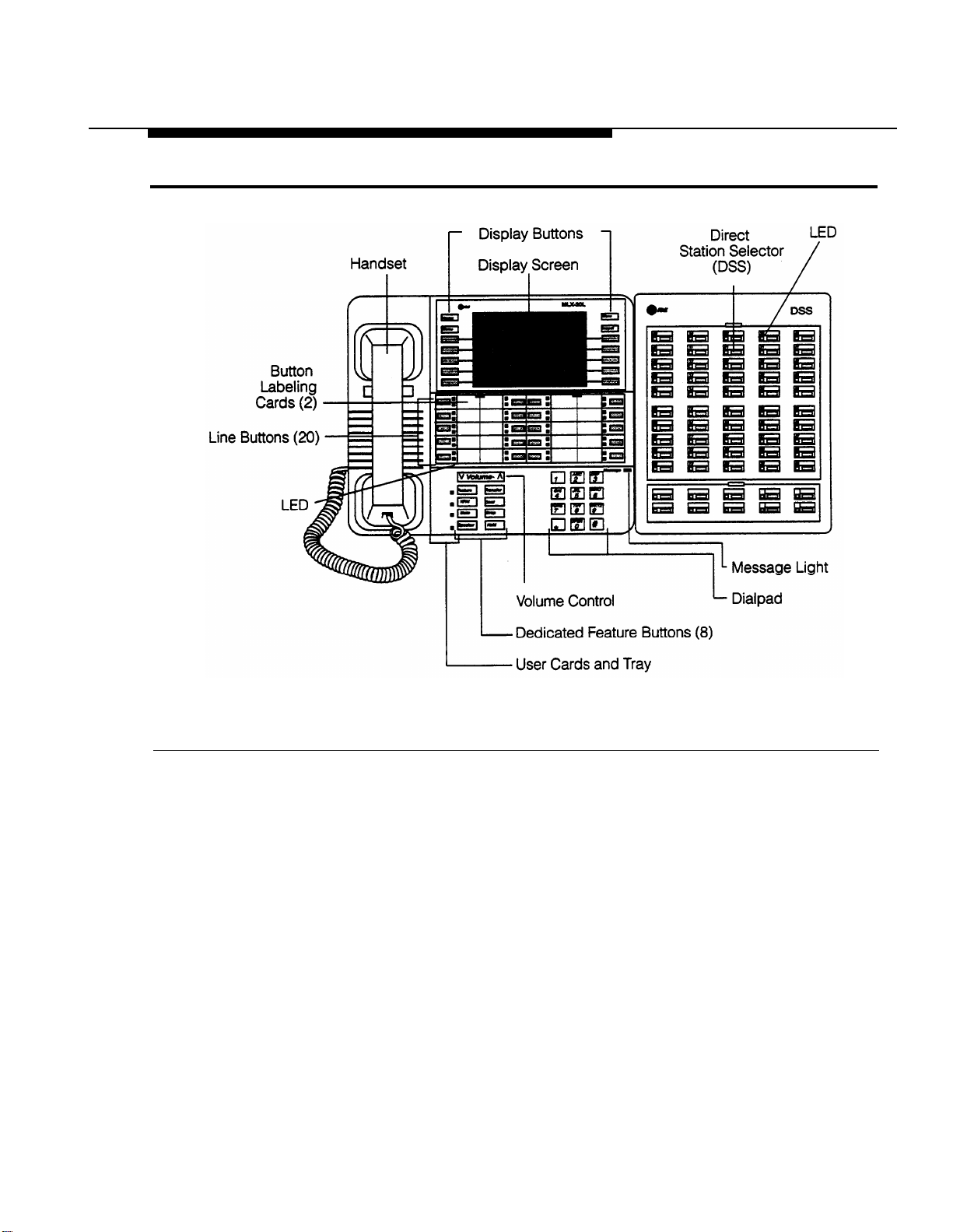
1-1. MLX-20L Telephone with Direct Station Selector
(DSS)
1-2. Console Overlay
1-3. System Busy Screen
22 Memory Cards
E
22-1. PCMCIA
22-2. Inserting
Button Diagrams
E-1.
MLX Telephone Button Diagram
(Hybrid/PBX Mode)
Memory Card
the Memory Card
1-3
1-5
1-12
22-3
22-4
E-2
E-2.
E-3.
E-4.
Analog Multiline Telephone Button Diagram
(Hybrid/PBX Mode)
MLX Telephone Button Diagram
(Key and Behind Switch Mode)
Analog Multiline Telephone Button Diagram
(Key and Behind Switch Mode)
Programming Summary xv
E-3
E-4
E-5
Page 16

Tables
1
4
9
Programming Basics
1-1.
1-2.
1-3.
Fixed Display Buttons
Programming Menu Options
Exiting System Programming
System Operator Positions
4–1.
Maximum Number of Operator Positions
PRI Facilities
9-1.
9-2.
Timers and Counters
Special Services Table
1-4
1-11
1-12
4-2
9-23
9-39
20
21
xvi Programming Summary
Data Features
20-1.
Data Features: Programming Procedures
Integrated Administration
21-1. Programming through Integrated Administration
21–2. Database Reconciliation Rules
20-2
21-3
21-5
Page 17

Tables
22 Memory Cards
23
C
22-1. Memory Card Formatting Messages
22-2. Memory Card Backup/Automatic Backup Error
Messages
22-3. Memory Card Restore Error Messages
Centralized Telephone Programming
23-2. Telephone Programming Codes
23-2. Features That Can Be Copied: All Telephones
23-3. Features That Can Be Copied: Direct-Line
Consoles Only
LED Displays
C-1. Line or Trunk Feature Status
22-6
22-9
22-17
23-7
23-12
23-15
C-2
C-2. Telephone Feature Status For DSS Console Only
Programming Summary xvii
C-3
Page 18

Tables
D
F
H
General Feature Use and Telephone Programming
D-1.
D-2.
D-3.
D-4.
Telephone and Operator Feature
Programming Analog Multiline Telephones
Programming MLX 10 Telephones
Programming MLX Display Telephones
Using the Display
D-5
D-13
D-14
D-15
Sample Reports
F-1.
F-2.
Reports Contents
System Reports
F-1
F-3
Programming Special Characters
H-1.
H-2.
H-3.
H-4.
xviii Programming Summary
Single Line Telephones
Analog Multiline Telephones
MLX Non-Display Telephones
MLX Display Telephones
H-2
H-3
H-4
H-5
Page 19

Safety
The exclamation point in an equilateral
triangle is intended to alert the user to
the presence of important operating and
maintenance (servicing) instructions in
the literature accompanying the product.
IMPORTANT SAFETY INSTRUCTIONS
When installing telephone equipment, always follow basic safety precautions
to reduce the risk of fire, electrical shock, and injury to persons, including:
■ Read and understand all instructions.
■
Follow all warnings and instructions marked on or packed with the
product.
■ Never install telephone wiring during a lightning storm.
■
Never install a telephone jack in a wet location unless the jack is
specifically designed for wet locations.
■
Never touch uninsulated telephone wires or terminals unless the
telephone wiring has been disconnected at the network interface.
■
Use caution when installing or modifying telephone lines.
■
Use only AT&T-manufactured MERLIN LEGEND Communications
System circuit modules, carrier assemblies, and power units in the
MERLIN LEGEND Communications System (511 A) control unit.
■
Use only AT&T-recommended/approved MERLIN LEGEND
Communications System accessories.
■
If equipment connected to the analog station modules (008, 408, 408
GS/LS) or to the MLX telephone modules (008 MLX, 408 GS/LS-MLX)
is to be used for in-range out-of-building (IROB) applications, IROB
protectors are required.
■
Do not install this product near water, for example, in a wet basement
location.
■
Do not overload wall outlets, as this can result in the risk of fire or
electrical shock.
Programming Summary xix
Page 20

Safety
■
The MERLIN LEGEND Communications System is equipped with a
three-wire grounding-type plug with a third (grounding) pin. This plug
will fit only into a grounding-type power outlet. This is a safety feature.
If you are unable to insert the plug into the outlet, contact an
electrician to replace the obsolete outlet. Do not defeat the safety
purpose of the grounding plug.
■
The MERLIN LEGEND Communications System requires a
supplementary ground.
■ Do not attach the power supply cord to building surfaces. Do not allow
anything to rest on the power cord. Do not locate this product where
the cord will be abused by persons walking on it.
■ Slots and openings in the module housings are provided for
ventilation. To protect this equipment from overheating, do not block
these openings.
■ Never push objects of any kind into this product through module
openings or expansion slots, as they may touch dangerous voltage
points or short out parts, which could result in a risk of fire or electrical
shock. Never spill liquid of any kind on this product.
■ Unplug the product from the wall outlet before cleaning. Use a damp
cloth for cleaning. Do not use cleaners or aerosol cleaners.
■
Auxiliary equipment includes answering machines, alerts, modems,
and fax machines. To connect one of these devices, you must first
have a Multi-Function Module (MFM).
■ Do not operate telephones if chemical gas leakage is suspected in the
area. Use telephones located in some other safe area to report the
trouble.
WARNING:
■
For your personal safety, DO NOT install an MFM yourself.
■
ONLY an authorized technician or dealer representative shall install,
set options, or repair an MFM.
■ To eliminate the risk of personal injury due to electrical shock, DO NOT
attempt to install or remove an MFM from your MLX telephone.
Opening or removing the module cover of your telephone may expose
you to dangerous voltages.
SAVE THESE INSTRUCTIONS
xx
Programming Summary
Page 21

About This Book
The MERLIN LEGEND Communications System is an advanced digital
switching system that integrates voice and data communications features.
The system’s power and versatility is due in part to its many options and
features. This book is a reference, containing summaries of all the
programming procedures you need to enable the system to function at peak
efficiency. The material is presented in the order in which you would program
a new system.
Intended Audience
This book is intended for qualified service personnel and technicians.
Additional information is available as follows:
■ More detailed procedures for system programming, along with
information on how to program on the system programming console
and on a PC, can be found in System Programming.
■ Complete instructions on using SPM can be found in System
Programming and Maintenance (SPM).
■ Detailed information about all of the features described here can be
found in the Feature Reference.
■ Detailed instructions on how to choose among the many options
provided for each feature can be found in System Planning.
Programming Summary xxi
Page 22

Terms and Conventions Used
“Related Documents,” later in this section, provides a complete list of system
documentation together with ordering information.
In the U.S.A. only,
(1-800-628-2888) 24 hours a day. Call the Helpline, or your AT&T
representative, if you need assistance when installing, programming, or
using your system.
AT&T provides a toll-free customer Helpline
Terms and Conventions Used
In this document, the terms in the following list are used in preference to
other, equally acceptable terms for describing communications systems.
Lines, Trunks and Facilities
Facility is a general term that designates a communications path between a
telephone system and the telephone company central office. Technically a
trunk connects a switch to a switch, for example the MERLIN LEGEND
Communications System to the central office. Technically, a line is a loopstart facility or a communications path that does not connect two switches,
for example, an intercom line or a Centrex line. However, in actual usage, the
terms line and trunk are often applied interchangeably. In this book, we use
line/trunk and lines/trunks to refer to facilities in general. Specifically, we refer
to digital facilities. We also use terms such as personaI line, ground-start
trunk, DID trunk, and so on. When you talk to your local telephone company
central office, ask them what terms they use for the specific facilities they
connect to your system.
Some older terms have been replaced with newer terms. The following list
shows the old term on the left and the new term on the right.
trunk module
trunk jack
station
station jack
xxii
Programming Summary
line/trunk module
line/trunk jack
extension
extension jack
Page 23

Terms and Conventions Used
analog data station modem data station
digital data station 7500B data station
analog voice and analog data station
digital voice and analog data station
analog voice and modem data
MLX voice and modem data
analog data only station modem data only station
digital data only station 7500B data only station
digital voice and digital data station
MLX voice and 7500B data
station
Typographical Conventions
Certain type fonts and styles act as visual cues to help you rapidly
understand the information presented:
Example Purpose
It is very important that you follow
these steps. You must attach the
wristband before touching the
connection.
The part of the headset that fits over
one or both ears is called a
headpiece.
If you press the
Feature
button on
an MLX display telephone, the
display lists telephone features you
can select. A programmed Auto Dial
button gives you instant access to
an inside or outside number.
Choose
Ext Prog
from the display
screen.
To activate Call Waiting, dial
*11.
Italics indicate emphasis.
Italics also set off special terms.
The names of fixed-feature, factoryimprinted buttons appear in bold.
The names of programmed buttons
are printed as regular text.
Plain constant-width type indicates
text that appears on the telephone
display or PC screen.
Constant-width type in italics
indicates characters you dial at the
telephone or type at the PC.
Programming Summary xxiii
Page 24

Security
Product Safety Labels
Throughout these documents, hazardous situations are indicated by an
exclamation point inside a triangle and the word caution or warning.
WARNING:
Warning indicates the presence of a hazard that could cause death or
severe personal injury if the hazard is not avoided.
CAUTION:
Caution indicates the presence of a hazard that could cause minor
personal injury or property damage if the hazard is not avoided.
Security
Certain features of the system can be protected by passwords to prevent
unauthorized users from abusing the system. You should assign passwords
wherever you can and limit knowledge of such passwords to three or fewer
people.
Nondisplaying authorization codes and telephone numbers provide another
layer of security. For more information, see Appendix A, “Customer Support
Information.”
Related Documents
In addition to this book, the documents listed below are part of the
documentation set. Within the continental United States, these documents
can be ordered from the AT&T Customer Information Center by calling
1-800-432-6600.
xxiv
Programming Summary
Page 25

Related Documents
Document No.
Title
System Documents
555-630-117
Introduction
555-630-118 System Manager’s Guide
555-630-110
555-630-115
555-630-116
555-630-111
555-630-112
555-630-113
Feature Reference
Equipment and Operations Reference
Pocket Reference
System Programming
System Planning
System Planning Forms
Telephone User Support
555-630-122
MLX-10D™, MLX-10DP™, MLX-28D™, and MLX-20L™
Display Telephones User’s Guide
555-630-150
555-630-153
555-630-124
555-630-151
555-630-120
555-630-126
MLX-10D Display Telephone Tray Cards (5 cards)
MLX-28D and MLX-20L Telephone Tray Cards (5 cards)
MLX-10™ Nondisplay Telephone User’s Guide
MLX-10 Nondisplay Telephone Tray Cards (6 cards)
Analog Multiline Telephones User’s Guide
Single-Line Telephones User’s Guide
System Operator Support
555-630-134
555-630-132
555-630-136
555-630-138
MLX Direct-Line Consoles Operator’s Guide
Analog Direct-Line Consoles Operator’s Guide
MLX Queued Call Console Operator’s Guide
MDC 9000 and MDW 900 Telephones User’s Guide
Miscellaneous User Support
555-630-130 Calling Group Supervisor’s Guide
555-630-129
Data User's Guide
Documentation for Qualified Technicians
555-630-140
Installation, Programming, & Maintenance (IP&M) Binder.
Programming Summary xxv
Page 26

How to Comment on This Document
How to Comment on This Document
We welcome your comments, both good and bad. Please use the feedback .
form on the next page to let us know how we can continue to serve you. If the
feedback form is missing, write directly to:
Documentation Manager
AT&T
211 Mount Airy Road
Room 2W226
Basking Ridge, NJ 07920.
xxvi
Programming Summary
Page 27

Programming Basics
This chapter covers the information you need to know before you begin
system programming.
It describes the following:
■
How to use the system programming console, buttons, and overlay
1
■ Types of programming
■
Programming summary contents
■ Programming basics
■ Programming menu options
■ What system components require idle states for programming
Programming Basics 1-1
Page 28

System Programming Console
System Programming Console
The system programming console is an MLX-20L telephone connected to the
system programming jack. When you begin system programming on a new
system for the first time, the console must be connected to the first jack on the
first 008 MLX module or 408 GS/LS-MLX module (Release 2.0 and later
versions). This jack is factory set as the system programming jack and as an
operator position. When you program for the first time, you can change the
system programming jack to any one of the first five jacks on the first 008 MLX
module or 408 GS/LS-MLX module (Release 2.0 and later versions). This
allows you to program without interfering with the operator’s call handling.
You can also have one or two Direct Station Selectors (DSSs) connected to
the system programming console. Each DSS adds 50 extension buttons to the
console, which facilitates assigning features to telephones.
An MLX-20L telephone with a DSS is shown in Figure 1–1.
1-2 Programming Basics
Page 29
System Programming Console
Figure 1-1. MLX-20L Telephone with Direct Station Selector (DSS)
Programming Basics 1-3
Page 30

System Programming Console
Console Buttons
System programming is performed using the console’s 14 display-area
buttons. These buttons are arranged in two columns of seven buttons. The top
two buttons in each column have the same labels and functions regardless of
the screen display. This type of button is called a fixed display button. Table
1-1 describes the functions of the fixed display buttons.
Table 1-1. Fixed Display Buttons
Button
Home
Menu
More
Function
Return to normal call-handling mode after you finish programming.
Display the main menu shown in Figure 1–2.
Display more items when a menu is continued on more than one
screen, indicated by an angle bracket (>) on the upper right of the
screen.
Inspct
(Inspect) View a list of lines or extensions on which a feature is
programmed.
Console Overlay
The programmable line buttons are on the main part of the console. There are
actually 20 line buttons on the console, but you can use the console overlay to
program up to 34 lines buttons through centralized telephone programming.
Select
Page 1
to access line buttons 1 through 20 and
Page 2
to access line
button 21 to 34. You can also use the dialpad for entering feature and
programming codes.
Figure 1–2 illustrates the system console overlay.
1-4 Programming Basics
Page 31

System Programming Console
Line 1
Line 21
Line 14
Line 34
Figure 1-2. Console Overlay
Appendix E shows the button diagrams for the telephones used in the
communications system. Refer to this appendix when programming buttons
for other telephones.
Programming Basics 1-5
Page 32

Programming Information
Programming Information
This section covers basic system programming information. See System
Programming for more information.
Types of Programming
Listed below are the three types of programming available for the
communications system.
■
System Programming.
manager to program features that affect all or most system users, and
requires one of the following:
— An MLX-20L™ telephone connected to one of the first five jacks of
the first MLX module in the control unit.
This type of programming enables the system
— A PC with System Programming and Maintenance (SPM) software.
SPM emulates a system programming console on your PC. The PC
should be connected to the lower port (labeled ADMIN) on the
processor module. A PC with a modem can perform system
programming remotely through the public network or by
connecting to a tip/ring extension jack (012 or 008 OPT module) on
the communications system. A built-in modem in the processor
allows the PC and the communications system to communicate.
■
Extension Programming.
This type of programming enables
individual telephone users and system operators (except for QCC
operators) to change their telephone features to meet individual
needs. For details about extension programming, see the appropriate
user and operator guides.
1-6 Programming Basics
Page 33

Programming Information
■
Centralized Telephone Programming.
This type of programming
enables the system manager to program any feature that can be
programmed by individual telephone users or system operators. Some
features can be programmed only in centralized telephone
programming. Centralized telephone programming can be done on
the programming console or on a PC with the SPM software. See
Chapter 5 in System Programming.
NOTE:
If your system has the AT&T Integrated Solution II or AT&T Integrated Solution
III (IS II/III) UNIX
®
application, see Chapter 2 in System Programming for more
information.
Programming Basics 1-7
Page 34

Programming Information
Procedure Summary Contents
Each programming summary contains a general description of the feature
and provides the following programming information.
Programmable by
Mode
Idle condition
Planning form
Factory setting
Valid entries
Inspect
Copy option
Indicates who has permission to use the procedure.
Specifies which system mode supports the procedure:
Key, Hybrid/PBX, Behind Switch, or a combination
Specifies the idle state required before the procedure
can be performed.
Indicates the planning forms that provide information for
the procedure.
Shows the default settings, if any, for equipment or
features affected by the procedure.
Specifies the characters, numbers, or values accepted
during data entry.
Specifies whether or not the feature status can be
verified using the Inspect feature.
Indicates whether or not the feature programmed with
the procedure can be copied to another system
component.
Console Procedure
PC Procedure
1-8 Programming Basics
Provides a summary of the procedure steps using the
system console.
Provides a summary of the procedure steps using SPM.
Page 35

Programming Information
Programming Basics
To begin programming, do the following:
On the console
Select
Menu → Sys Program → Exit:
The System Programming menu is displayed.
On the PC
Type
SPM → [Enter]
→
Press any key → [F1]
→
[F5]:
The System Programming menu is displayed.
In most cases, to exit from a screen without making any changes, press
Exit
or [F5]. Exceptions are noted as part of a procedure.
Ordinarily you complete a procedure by pressing
information you have programmed. Occasionally you press
Enter
( [F10] ) to save the
Exit
( [F5] ) and
go back to the previous screen.
If you are programming sequentially numbered extensions or trunks, you may
have the option of pressing
Next
( [F8] ) to save your entry and automatically
provide the number of the next extension or trunk in the sequence, thus
saving you a couple of steps.
When you have completed a procedure, pressing
Exit
( [F5] ) takes you up
one screen in the menu hierarchy.
In most cases, you will be at an intermediate step in the procedure you have
just completed. At that point, you can select one of the options shown on the
screen and continue programming, or you can press
Exit
again. This usually
takes you back to the system Programming menu. If not, you again have the
option of continuing to program from the current screen or pressing
Exit
again.
In a few cases, pressing
Exit
brings you back to the System Programming
menu where you can select another option to program or exit from system
programming.
Programming Basics 1-9
Page 36

Programming Information
Table 1-2. Programming Menu Options
Option
System
SysRenumber
Operator
LinesTrunks
Extensions
Options
Tables
AuxEquip
Description
Set system operating conditions.
Select the system numbering plan and/or reassign extension
numbers with 1- to 4-digit numbers that are more appropriate
or convenient for your company.
Assign or remove operator positions and program operator
features (such as Operator Hold Timer or QCC options).
Program line/trunk options.
Program features for extensions (such as restrictions and line
assignments).
Program systemwide features (such as Transfer Return and
Delay Ring).
Program features that require entering information in a table
(such as Allowed Lists and Disallowed Lists).
Program auxiliary equipment connected to the system (such
as loudspeaker paging and fax).
NightSrvce
Labeling
Program Night Service features.
Program the labels shown on display telephones (such as
entries in the System Directory and Posted Messages).
Data
Print
Specify extensions that need voice and data capability.
Print system programming reports (such as system
configuration and extension assignments).
Cntrl-Prog
Perform centralized telephone programming (assign features
to specific buttons on telephones).
Language
Select the language that your console uses to display text on
the screens [English (default), French, and Spanish].
1-10 Programming Basics
Page 37

Idle States
Exiting System Programming
Use the information in Table 1–3 to return to the System Programming menu,
the main menu (Menu Mode screen), or to the Home screen from within a
programming screen.
Table 1-3. Exiting System Programming
To return to ...
Previous menu
Main Menu
Normal call
handling
On the console press: On the PC press:
Exit
Menu
Home
[F5]
[End]
[Home]
Idle States
Some programming procedures can be started only when the entire system,
or some part of it, such as a trunk or an extension, is idle (not in use). Some
procedures require that a trunk or extension be idle only at the instant of
programming. Lengthy procedures require the system, trunk, or extension to
remain idle until programming is completed. These procedures wait for the
system, trunk, or extension to become idle and then prevent the initiation of
any new calls. This condition is called forced idle.
NOTE:
If a procedure requires an idle condition, do the programming outside of
normal business hours.
If a procedure requires that the system be idle and the system is busy when
you begin, you see the screen shown in Figure 1-3.
Programming Basics 1-11
Page 38

Idle States
System Busy Pls Wait
Dial Code: nnnn
Slot/Port: ss/pp
nnnn = a previously entered extension
ss/pp = the slot and port number of the
busy extension
Exit
Enter
Figure 1-3. System Busy Screen
The screen changes to the appropriate programming screen when the system
is no longer busy.
System Forced Idle
When the entire system is forced idle, no calls can be made or received. The
following procedures can be performed only when the entire system (every
line and every extension) is idle:
■
Select system mode.
■ Identify system operator positions.
■
Renumber system.
■ Renumber boards.
■ Identify telephones with voice signal pairs for the Voice Announce to
Busy feature.
■ Identify telephones that need voice and data features.
■
Restore system programming information.
■ Identify the Music On Hold jack.
1-12 Programming Basics
Page 39

Idle States
When the system is forced idle, the following occurs: multiline telephone users
hear a signal, indicating that the telephone cannot be used; display telephone
users see the message
Wait: System Busy;
single-line telephone users do
not hear a dial tone.
Line or Trunk Idle
Since these procedures require the line or trunk to be idle only at the instant of
programming, the line or trunk is not forced idle (as described in the previous
paragraph). The following procedures can be performed only when the line or
trunk being programmed is idle:
■ Identify loudspeaker paging extension jack.
■ Assign trunks to pools.
■ Specify incoming or outgoing DID or tie trunk type.
■ Specify tie trunk direction.
■ Specify tie trunk E&M signal.
Extension Forced Idle
When a telephone or data terminal is forced idle, no calls can be made or
received on that telephone or data terminal. The following procedures can be
performed only when the telephone or data terminal being programmed is
idle:
■
Assign call restrictions.
■
Assign pool dial-out restrictions.
■
Copy extension assignments.
■
Assign lines, trunks, or pools to extensions.
■ Assign labels to a personal directory.
■ Use centralized telephone programming.
Programming Basics 1-13
Page 40

Idle States
When the telephone is forced idle, the following occurs: multiline telephone
users hear a signal, indicating that the telephone cannot be used; display
telephone users see the message
Wait: System Busy;
single-line telephone
users do not hear a dial tone.
100D Module Idle
The following procedures can be performed only when the 100D module is
idle:
■ Specify board type.
■ Specify frame format.
■ Specify board signaling format.
■ Specify board suppression format.
■ Specify board facility compensation.
Forced Idle Reminder Tones
The forced idle reminder tone is a high-low “doorphone” tone—400 ms of
667 Hz tone followed by 400 ms of 571 Hz. The tone is provided under the
following circumstances:
■
At the extension, to remind the user that the system or the extension is
in the forced idle state
■
At the programming console or at a PC running SPM, to remind the
system manager that the system (or at least one extension) is in the
forced idle state because of administrative activity
In Release 1.1 and higher of the communications system, forced idle reminder
tones occur every 20 seconds. You can adjust the volume of these tones with
the volume control.
1-14 Programming Basics
Page 41

Basic System Operating
Conditions
2
The procedures in this section are all related to the system rather than to the
operation of telephones, operator positions, lines, or trunks. These are
operating conditions that must be set only once, when the system is new, or
when you reset the system defaults.
NOTE:
You must reset the system time when Daylight Savings Time begins and ends.
Basic System Operating Conditions 2-1
Page 42

System Restart
System Restart
CAUTION:
This procedure is for qualified support personnel only.
Use this procedure to perform a System Restart (cold start). All calls are
dropped when you perform this procedure. System programming is saved.
Telephones with the Extension Status feature may lose toll restrictions as a
result of a System Restart.
Summary: System Restart
Programmable by
Mode
Idle Condition
Planning Form
Factory Setting
Valid Entries
Inspect
Copy Option
Console Procedure
PC Procedure
Qualified support personnel
All
Not required
Not applicable
None
None
No
No
System → Restart → Yes
[F1]
→
[F1]
→
[F1]
2-2 Basic System Operating Conditions
Page 43

System Programming Position Assignment
System Programming Position
Assignment
Use this procedure to reassign the extension used for system programming.
This extension should not be the same extension as that used for the operator
position. The system programming position can be reassigned only to one of
the first five extension jacks on the first MLX module. Only one system
programming console is allowed per system.
If you are programming on the console, be aware of the following:
■ The console must be connected to the extension currently assigned
for system programming.
■ As soon as you change the system programming extension, the
system programming session is terminated. To proceed with system
programming, you must connect the system programming console to
the newly assigned extension and enter system programming again.
NOTE:
The telephone used for system programming must be an MLX-20L.
Basic System Operating Conditions 2-3
Page 44

System Programming Position Assignment
Summary: System Programming Position
Assignment
Programmable by
Mode
Idle Condition
Planning Form
Factory Setting
Valid Entries
Inspect
Copy Option
Console Procedure
PC Procedure
System manager
All
Not required
Form 1, System Planning
First extension jack on the first MLX module (also set as
an operator position)
Extension number of one of the first five extension jacks
on the first MLX module
No
No
System → SProg Port → Drop → Dial ext. no. → Enter
→
Exit
[F1]
→
[F2]
→
[Alt] + [P]
→
Type ext. no. → [F10]
→
[F5]
2-4 Basic System Operating Conditions
Page 45

System Language
System Language
Your communications system offers you a choice of three languages (English,
French, and Spanish) for the following options:
■ System language.
■
Station Message Detail Recording (SMDR) reports. See “System
Features.”
■
Print reports. See “Printing Reports.”
■
Extensions. See “Optional Telephone Features.”
Use this procedure to set the system language. See the sections listed above
to set a different language for an MLX display telephone, SMDR reports and
printer reports.
NOTE:
MERLIN LEGEND Communication System Release 1.0 does not offer a choice
of languages.
Summary: System Language
Programmable by
Mode
Idle Condition
Planning Form
Factory Setting
Valid Entries
Inspect
Copy Option
Console Procedure
System manager
All
Not required
Form 1, System Planning
English
English, French, Spanish
No
No
More → Language → SystemLang → Yes → Select a
language → Enter
PC Procedure
[PgUp]
→
[F6]
→
[F1]
→
[F3]
→
Select a language → [F10]
Basic System Operating Conditions 2-5
Page 46

Board Renumbering
Board Renumbering
CAUTION:
This procedure is to be performed by qualified support personnel only.
Use this procedure to renumber boards that have already been installed. This
procedure restarts the system (system programming is not lost). Note that this
is not the same procedure used with the Boards option, which is available to
qualified service personnel with SPM only.
Summary: Board Renumbering
Programmable by
Mode
Idle Condition
Planning Form
Factory Setting
Valid Entries
Inspect
Copy Option
Console Procedure
PC Procedure
Qualified support personnel only
All
System idle
Not applicable
None
Not applicable
Not applicable
Not applicable
System → Board Renum → Yes
[F1]
→
[F4]
→
[F2]
2-6 Basic System Operating Conditions
Page 47

Mode of Operation
Mode of Operation
The system mode—Key, Behind Switch, or Hybrid/PBX—determines how the
system operates and directly affects the following operations:
■ How lines and/or trunks are provided to users
■ Types of operator consoles allowed
■ Features available
Changing this option causes a system restart and terminates the
programming session. You must enter system programming again to program
other features.
NOTE:
The Hybrid/PBX option is not available if the control unit processor module
has been modified to operate in Permanent Key mode only. See the
Equipment and Operations Reference.
The following options cannot be programmed for Behind Switch or Key mode
systems:
■
Automatic Route Selection (ARS)
■ Pools
■
Queued Call Consoles (QCCs) and associated features
■
Direct Inward Dialing (DID) Trunks
■ System Access buttons
■
Dial Plan Routing (PRI)
■
Call by Call Services
The Ground-Start trunks option cannot be
module has been modified for Permanent
programmed if the processor
Key mode operation only.
Basic System Operating Conditions 2-7
Page 48

Mode of Operation
Summary: Mode of Operation
Programmable by
Mode
Idle Condition
Planning Form
Factory Setting
Valid Entries
Inspect
Copy Option
Console Procedure
PC Procedure
System manager
All
System idle
Form 1, System Planning
Hybrid/PBX
Key, Behind Switch, Hybrid/PBX
No
No
System → Mode → Select mode → Enter
[F1]
→
[F3]
→
Select mode → [F10]
2-8 Basic System Operating Conditions
Page 49

Automatic Maintenance Busy
Automatic Maintenance Busy
Automatic Maintenance Busy allows the system to take a malfunctioning trunk
out of service for outgoing calls (incoming calls are never blocked). This
prevents faulty outside facilities from causing disruptions in outgoing calling
patterns.
For optimal performance, enable Automatic Maintenance Busy for Hybrid/PBX
systems with pooled trunks.
NOTE:
No more than 50 percent of the trunks in a trunk pool are allowed to be placed
in the maintenance busy state at one time unless: the central office has failed
to disconnect a trunk (which prevents anyone from using that trunk); or an
entire trunk module is manually taken out of use (a maintenance-busy state
deliberately caused by the user).
Basic System Operating Conditions 2-9
Page 50

Automatic Maintenance Busy
Summary: Automatic Maintenance Busy
Programmable by
Mode
Idle Condition
Planning Form
Factory Setting
Valid Entries
Inspect
Copy Option
Console Procedure
System manager
All
Not required
Form 1, System Planning
Disabled
Enabled, Disabled
No
No
To disable Automatic Maintenance Busy:
System → MaintenBusy → Disable → Enter → Exit
To enable Automatic Maintenance Busy excluding
tie trunks:
System → MaintenBusy → Enable → Enter → Exit
To enable/disable with tie trunks:
System → MaintenBusy → Enable → Enter
Enable
or
Disable → Enter → Exit
→
PC Procedure
To disable Automatic Maintenance Busy:
[F1]
→
[F6]
→
[F2]
→
To enable Automatic Maintenance Busy excluding
tie trunks:
[F1]
→
[F6]
→
[F1]
→
To enable/disable with tie trunks:
[F1]
→
[F6]
→
[F1]
→
2-10 Basic System Operating Conditions
[F10]
[F10]
[F10]
→
[F5]
→
[F5]
→
[F1] or [F2]
→
[F10]
→
[F5]
Page 51

Set System Date
Set System Date
The System Date feature allows you to set the month, day, and year that
appear on MLX display telephones and on Station Message Detail Recording
(SMDR) reports.
NOTE:
If you are planning to use the SMDR feature, make sure the current date is
set.
Summary: Set System Date
Programmable by
Mode
Idle Condition
Planning Form
Factory Setting
Valid Entries
Inspect
Copy Option
Console Procedure
PC Procedure
System manager
All
Not required
Form 1, System Planning
01-01-00
Month: 01 to 12
Day: 01 to 31
Year: 00 to 99
No
No
System → Date → Drop → Dial current date → Enter
Exit
[F1]
→
[F7]
→
[Alt] + [P]
→
Type current date → [F10]
→
[F5]
→
Basic System Operating Conditions 2-11
Page 52

Set System Time
Set System Time
The System Time feature allows you to set the time that appears on MLX
display telephones and on SMDR reports.
NOTE:
If you
accurately. If you change the system time while the system is in Night Service
mode, Night Service is deactivated and must be manually reactivated. If you
have installed applications such as Call Management System (CMS) or AUDIX
Voice Power®, you may need to set the time in the applications software
whenever you reset the system time.
Summary: Set System Time
are planning to use the SMDR feature, make sure the system time is set
Programmable by
Mode
Idle Condition
Planning Form
Factory Setting
Valid Entries
Inspect
Copy Option
Console Procedure
PC Procedure
System manager
All
Not Required
Form 1, System Planning
0000
0000 to 2359
No
No
System → Time → Drop → Dial current time → Enter
Exit
[F1]
→
[F8]
→
[Alt] + [P]
→
Type current time → [F10]
→
[F5]
→
2-12 Basic System Operating Conditions
Page 53

System Renumbering
3
The procedures in this section are used to assign the 2-digit, 3-digit, and Set
Up Space numbering plans.
NOTE:
System Renumbering is called Flexible Numbering in the MERLIN® II
Communications System. This is not the same as Board Renumbering, an
option used when modules in the control unit are changed.
Do not attempt to assign a numbering plan without Planning Forms 2a,
System Numbering: Extension Jacks; 2b, System Numbering: Digital
Adjuncts; and 2d, System Numbering: Special Renumbers. Form 6a, Optional
Operator Features, is needed to assign a DSS
This section contains the following programming procedures:
■
Select System Numbering Plan
■ Single Renumbering
■ Block Renumbering
■
Direct Station Selector (DSS)
Page
Page
Button Assignment
button.
System Renumbering 3-1
Page 54

Select System Numbering Plan
You select only one of the numbering plans (2-digit numbering, 3-digit
numbering, or Set Up Space numbering). In addition, you may need to
perform single and/or block renumbering. You do not need to assign DSS
Page
positions is connected to a DSS. No matter which procedures you need to
perform, assign the numbering plan first, then do single and/or block
renumbering, and finally, assign DSS
buttons unless the system programming console or one of the operator
Page
buttons (if necessary).
Use the single renumbering procedure any
are changing from or to are not sequential.
Block renumbering is quicker, but you can use block renumbering only when
the extension numbers you are changing from and to are sequential.
When trunk or extension modules are removed from the control unit, the
remaining modules must be rearranged so that no empty slots remain. The
system does not acknowledge any modules installed after an empty slot;
therefore, if the system is renumbered, extensions are not assigned to
extension jacks after the empty slots.
time the extension numbers you
3-2 System Renumbering
Page 55

Select System Numbering Plan
Select System Numbering Plan
WARNING:
To avoid possible loss of system programming information, renumber
the system before you program the rest of the options described in this
chapter.
The three available system numbering plans listed below appear on System
Planning Form 2a.
■
2-Digit.
plans to exceed that number in the foreseeable future. Each of the first
58 extension jacks is assigned a 2-digit extension number, beginning
with 10 and ending with 67. Any remaining extensions are assigned
4-digit numbers, starting with 6800 and ending with 6885.
This plan is for systems with fewer than 50 extensions and no
■
3-Digit.
This plan is for systems with 50 or more extensions or plans to
grow to that number in the foreseeable future. All extensions are
assigned a 3-digit number, starting with 100 and ending with 243.
■
Set Up Space.
This plan is for systems with a need to customize
extension numbers or use extension numbers of varying lengths (one
to four digits). All extensions are assigned 4-digit numbers in the 7000
range. Extension numbers 1000 through 6999 are also available for
use when you renumber.
In all three numbering plans, the system assigns 3-digit extension numbers to
pools (Hybrid/PBX only), calling groups, paging groups, remote access
codes, the Listed Directory Number, park codes, and Idle Line Access (Key
and Behind Switch modes). In addition, the system assigns 9 for Automatic
Route Selection (Hybrid/PBX only) and Idle Line Access (Key and Behind
Switch modes only). Zero (0) represents a special extension number—actually
a fixed dial code—for the primary operator or QCC queue. Any extension
number except 0 can be renumbered.
System Renumbering 3-3
Page 56

Select System Numbering Plan
Extension numbers can be composed of any combination of digits; however,
no number can begin with 0. Trunk numbers (801 to 880) are considered to .
be extensions and can be renumbered.
The system does not provide a message to indicate a successful renumber
when either the 2-digit or 3-digit numbering plan is selected. For the Set Up
Space numbering plan, the system provides a message indicating that all
extensions are in the 7000 range.
CAUTION:
Select
selecting the numbering plan. If you press
Exit
on the console or [F5] on the PC when you have finished
Home,
extensions may
remain in the forced idle condition (indicated when the LED next to each
DSS button is on). To restore extensions to their normal operating state,
restart the system.
Summary: Select System Numbering Plan
Programmable by
Mode
Idle Condition
Planning Form
Factory Setting
Valid Entries
Inspect
Copy Option
Console Procedure
System manager
All
System idle
Form 2a, System Numbering: Extension Jacks
2-digit
2-digit, 3-digit, Set Up Space
No
No
SysRenumber → Default Numbering → Select numbering
plan → Exit → Exit
PC Procedure
[F2]
→
[F1]
→
Select numbering plan → [F5]
→
[F5]
3-4 System Renumbering
Page 57

Single Renumbering
Single Renumbering
Use this procedure to assign a specified extension number to a telephone,
accessory, line, pool (Hybrid/PBX only), calling group, paging group) or
Listed Directory Number. Single renumbering is also used for Remote Access,
Park, Idle Line Access (Key and Behind Switch only), and Automatic Route
Selection (Hybrid/PBX only).
CAUTION:
Select
extensions. If you press
condition (indicated when the LED next to each DSS button is on). To
restore extensions to their normal operating state, restart the system.
When required, this procedure should be performed immediately following the
selection of a system numbering plan.
Exit
on the console or [F5] on the PC after renumbering
Home,
extensions may remain in the forced idle
Summary: Single Renumbering
Programmable by
Mode
Idle Condition
Planning Form
Factory Setting
Valid Entries
Inspect
Copy Option
Console Procedure
PC Procedure
System manager
All
System idle
Form 2a, System Numbering:
Form 2b, System Numbering:
Form 2d, System Numbering:
Not applicable
Old and new extension numbers
Yes
No
SysRenumber → Single → Select item → Dial old ext. no.
→
Enter → Dial new ext. no. → Enter → Exit → Exit
[F2]
→
[F2]
Type new ext. no. → [F10]
Extension Jacks
Digital Adjuncts
Special Renumbers
→
Select item → Type old ext. no. → [F10]
→
[F5]
→
[F5]
→
System Renumbering 3-5
Page 58

Block Renumbering
Block Renumbering
Use this procedure to assign extension numbers to a group of extensions,
accessories, or lines. Both the original numbers and the numbers they are
being changed to must be sequentially numbered.
When required, this procedure should be performed immediately following the
selection of a system numbering plan.
CAUTION:
Select
renumbering extensions. If you press
the forced idle condition (indicated when the LED next to each DSS
button is on). To restore extensions to their normal operating state,
restart the system.
Exit
on the console or [F5] on the PC when you have finished
Home,
extensions may remain in
3-6 System Renumbering
Page 59

Block Renumbering
Summary: Block Renumbering
Programmable by
Mode
Idle Condition
Planning Form
Factory Setting
Valid Entries
Inspect
Copy Option
Console Procedure
PC Procedure
System manager
All
System idle
Form 2a, System Numbering: Extension Jacks
Form 2b, System Numbering: Digital Adjuncts
Form 2d, System Numbering: Special Renumbers
Not applicable
Old and new extension numbers
Yes
Yes
SysRenumber → Block → Select type of group → Dial no.
of first group member → Enter → Dial no. of last group
member → Enter → Dial new beginning no. → Enter
→
Exit → Exit → Exit
[F2]
→
[F3]
→
Select type of group → Type no. of first
group member
→
[F10]
→
→
[F10]
→
Type no. of last group member
Type new beginning no. → [F10]
→
[F5]
→
[F5]
→
[F5]
System Renumbering 3-7
Page 60

Direct Station Selector (DSS) Page Buttons
Direct Station Selector (DSS) Page
Buttons
Use this procedure to set the three
the system numbering plan. This procedure assigns extension numbers to
DSS buttons. You cannot program individual buttons on a DSS; this is the only
method for programming DSS buttons.
Page
each
numbers: Page 1: 0 to 49; Page 2: 50 to 99; Page 3: 100 to 149.
If two DSSs are attached, each
range of 100 extension numbers. If two DSSs are attached to the console,
change the factory setting so that the difference between extension numbers
assigned to the range is at least 100. For example, assign Page 1 to begin
with extension 10, Page 2 to begin with extension 110, and Page 3 to begin
with extension 210.
Operator Park Zone codes must be included in the extension number range
specified for one of the
button assignment should be sequential. If only one DSS is attached,
Page
button assignment sets the console for a range of 50 extension
Page
buttons.
Page
Page
buttons on the DSS to correspond to
button assignment sets the console for a
CAUTION:
Select
procedure. If you press
condition (the LED next to each DSS button is on), and the system may
have to be restarted.
3-8 System Renumbering
Exit
on the console or [F5] on the PC when you have finished this
Home,
extensions may remain in the forced idle
Page 61

Direct Station Selector (DSS) Page Buttons
Summary: Assign Direct Station Selector Page
Buttons
Programmable by
Mode
Idle Condition
Planning Form
Factory Setting
Valid Entries
Inspect
Copy Option
Console Procedure
PC Procedure
System manager
All
Not required
Form 6a, Optional Operator Features
Page 1=0; Page 2=50; Page 3=100
1, 2, 3
Yes
No
SysRenumber → Single → More → DSS Buttons → Dial
page no. → Enter → Dial first ext. no. → Enter → Exit
Exit
[F2]
→
[F2]
→
first ext. no.
→
[PgUp]
[F10]
→
→
[F1]
[F5]
→
Type page no. → [F10]
→
[F5]
→
Type
→
System Renumbering 3-9
Page 62

Direct Station Selector (DSS) Page Buttons
3-10 System Renumbering
Page 63

System Operator Positions
4
A system operator position, for a Queued Call Console (QCC) operator or a
Direct-Line Console (DLC) operator, should be programmed before you
program lines or trunks.
The Queued Call Console (QCC) operator position is available only for
Hybrid/PBX systems. The Direct-Line Console (DLC) operator position is
available in any mode and must be programmed if you have Call
Management Systems connected to any operator extension jacks.
System Operator Positions 4-1
Page 64

Primary Operator Positions
Table 4-1 shows the maximum number of operator positions allowed for any
one system.
Table 4-1. Maximum Number of Operator Positions
Position Type
QCC
DLC
Total QCC + DLC
Any combination of operator positions can be assigned as long as no more
than four operator positions are QCCs and the total number of operator
positions does not exceed eight.
If you want to designate a new operator position and the system already has
the maximum number of operator positions, you must change an existing
operator position to a nonoperator position before you designate a new
operator position.
Type of Telephone
MLX-20L
MLX-20L
MLX-28D
Analog multiline telephones
MERLIN II Display Consoles
Maximum Positions
4
8
8
NOTE:
When you change an extension to an operator position, or vice versa, the
system returns the port (extension jack) type of that extension to the factory
setting. You must reprogram lines and any features for that telephone or
console. You may also need to change any attached accessory equipment
and optional features.
4-2 System Operator Positions
Page 65

Primary Operator Positions
Primary Operator Positions
The primary operator position is the extension to which your call is directed
when 0 is dialed on a System Access button. The first extension jack on the
first MLX module in your system is assigned as the primary operator position.
If your system has QCC operator positions, this position must be changed
from the factory setting (DLC) to a QCC operator position. (The primary
operator extension cannot be changed from the first extension on the first
MLX module.)
QCC Operator Position
The QCC operator position is available only for Hybrid/PBX systems. The DLC
operator position is available in any mode and must be programmed if you
have Call Management Systems connected to any operator extension jacks.
QCC System Operator Positions.
This procedure applies to Hybrid/PBX systems only.
IMPORTANT:
If you want to add or remove QCC operator positions, the following
conditions apply:
■ If other QCC positions remain in your system, the primary QCC
operator position cannot be removed.
■ When QCC operator positions are added, the primary QCC
operator position should be the first one added.
■ If QCC operator positions are being removed, the primary QCC
operator position must be the last one removed.
System Operator Positions 4-3
Page 66

QCC Operator Position
Summary: QCC Operator Positions
Programmable by
Mode
Idle Condition
Planning Form
Factory Setting
Valid Entries
Inspect
Copy Option
Console Procedure
PC Procedure
System manager
Hybrid/PBX
System idle
Form 2a, System Numbering: Extension Jacks
Type: DLC
First or fifth extension jack on MLX module (maximum:
two per module; maximum: four QCCs per system)
Yes
No
Operator → Positions → Queued Call → Dial ext.no.
→
Enter → Store All
[F3]
→
[F1]
→
[F2]
→
Type ext. no. → [F10]
→
[F3]
4-4 System Operator Positions
Page 67

DLC Operator Positions
DLC Operator Positions
DLC operator positions can be assigned to the first and fifth extension jacks
on the first modules with digital or analog multiline extension jacks. A
maximum of eight DLC operator positions can be assigned. Any combination
of operator positions can be assigned as long as there are no more than four
QCC operator positions and no more than a total of eight operator positions.
Use this procedure to specify extensions that serve as central answering
positions for all incoming calls, for Call Management Systems (CMSs)
connected to operator extension jacks, or as calling group supervisor
extensions. (You do not need to use this procedure in a Key or Behind Switch
system unless you have more than one DLC position.) For a new system,
remove the factory-set DLC operator position assignment for any telephone
not used as an operator position.
Lines and trunks are assigned on individual buttons.
The system programming console can have several incoming calls ringing
simultaneously.
Each CMS requires two DLC operator positions to connect the equipment and
one position to serve as CMS supervisor.
System Operator Positions 4-5
Page 68

DLC Operator Positions
Summary: Identify or Remove DLC Operator
Positions
Programmable by
Mode
Idle Condition
Planning Form
Factory Setting
Valid Entries
Inspect
Copy Option
Console Procedure
PC Procedure
System manager
All
System idle
Form 2a, System Numbering: Extension Jacks
Type: DLC
First or fifth extension jack on MLX module (maximum:
two per module; maximum: eight DLCs per system)
Yes
No
Operator → Positions → Direct Line → Dial ext. no.
→
Enter → Store All
[F3]
→
[F1]
→
[F1]
→
Type ext. no. → [F10]
→
[F3]
4-6 System Operator Positions
Page 69

Lines and Trunks
5
The procedures in this section are used to assign optional features to
individual lines and trunks. The following optional features can be assigned:
■
Type of Trunk
■
Outmode Signaling for Loop- or Ground-Start Trunks
■
Rotary Trunk Digit Transfer
■ Disconnect Signaling Reliability
■
Toll Type
■ Hold Disconnect Interval
■
Principal User for Personal Line
■
QCC Queue Priority
■
QCC Operator to Receive Calls
■ Incoming Call Line Identification Delay
■
Trunks to Pools Assignment
The Copy Options feature (described at the end of this section) allows you to
copy several optional features from an idle trunk. This option eliminates the
need to individually enter each feature.
Lines and Trunks 5-1
Page 70

Type of Trunk
Separate sections cover “DS1 Facilities,”
“Tie Trunks,” “DID Trunks,” and “PRI
Facilities.”
A slot is the physical location of the individual module on the control unit.
There is a maximum of 17 slots which are numbered as follows:
■ Basic carrier: slots 1 through 5
■ First expansion carrier: slots 6 through 11
■ Second expansion carrier: slots 12 through 17
A port is a line or trunk jack on the module. Individual modules support
different numbers of ports. On any module, port 1 is the lowest physical jack
position. Lines connect equipment to the switch and trunks connect a switch
to a switch. Lines and trunks have logical IDs, a unique numeric identifier for
each extension and trunk jack in the communications system control unit.
Lines are numbered from 1 to 144, while trunks are numbered from 801 to
880. An MLX extension port has 2 logical IDs per 1 physical jack.
5-2 Lines and Trunks
Page 71

Type of Trunk
Type of Trunk
Use this procedure to specify the type of trunk, loop-start (LS) or ground-start
(GS), for each outside trunk connected to one of the following modules:
■ 400 GS/LS
■ 408 GS/LS
■ 800 GS/LS
■ 408 GS/LS-MLX
■ 800 GS/LS-ID (loop-start trunks only)
Any combination of trunk types (all loop-start, all ground-start, or some of
each) is permissible.
This procedure is not used for a system registered with a KF registration
number (Key or Behind Switch). Ground-start trunks are allowed only for
systems with an MF (Hybrid) or PF (PBX) registration number.
Summary: Type of Trunk
Programmable by
Mode
Idle Condition
Planning Form
Factory Setting
Valid Entries
Inspect
Copy Option
Console Procedure
System manager
All
Not required
Form 2c, System Numbering: Line/Trunk Jacks
All loop-start
All Ground, All Loop, Ground-Start, Loop-Start
Yes
Yes
LinesTrunks → LS/GS/DS1 → Dial slot no. → Enter
Select trunk type → Dial port no. → Enter → Exit → Exit
PC Procedure
[F4]
Type port no. → [F10]
→
[F1]
→
Type slot no. → [F10]
→
[F5]
→
[F5]
→
Select trunk type
→
→
Lines and Trunks 5-3
Page 72

Outmode Signaling for Loop- or Ground-Start Trunks
Outmode Signaling for Loop- or
Ground-Start Trunks
Use this procedure to identify either touch-tone signaling or rotary-dial
signaling for outgoing calls placed by using the specified loop- or groundstart trunk.
NOTE:
Since the factory setting is touch-tone, this procedure is not required if your
system has only touch-tone lines/trunks.
5-4 Lines and Trunks
Page 73

Outmode Signaling for Loop- or Ground-Start Trunks
Summary: Outmode Signaling for Loop- or
Ground-Start Trunks
Programmable by
Mode
Idle Condition
Planning Form
Factory Setting
Valid Entries
Inspect
Copy Option
Console Procedure
System manager
Loop-Start: All; Ground-Start: Hybrid/PBX only:
Not required
Form 2c, System Numbering: Line/Trunk Jacks
Touch-tone
Touch-tone, Rotary
No
Yes
To program a single line/trunk:
LinesTrunks → TT/LS Disc → Outmode → Select entry
mode → Dial no. of the line/trunk → Enter → Exit → Exit
→
Exit
To program a block of lines/trunks:
LinesTrunks → TT/LS Disc → OutMode → Select block of
lines/trunks → Toggle LED On/Off → Enter → Exit → Exit
→
Exit
PC Procedure
To program a single line/trunk:
[F4]
→
[F3]
→
[F1]
→
[F6]
→
Type no. of the line/trunk → [F10]
→
[F5]
→
[F5]
→
[F5]
To program a block of lines/trunks:
[F4]
→
[F3]
→
[F1]
→
Select block of lines/trunks → Toggle
letter G On/Off → [F10]
→
[F5]
→
[F5]
→
Lines and Trunks 5-5
[F5]
Page 74

Rotary Trunk Digit Transfer
Rotary Trunk Digit Transfer
Use this procedure to designate whether dialed digits on rotary dial
lines/trunks are sent one by one as they are dialed (no delay), or are stored
and sent when dialing is completed (delay). Contact your service provider for
more information about the appropriate setting.
Summary: Rotary Trunk Digit Transfer
Programmable by
Mode
Idle Condition
Planning Form
Factory Setting
Valid Entries
Inspect
Copy Option
Console Procedure
PC Procedure
System manager
All
Not required
Form 8a, System Features
No Delay
Delay, No Delay
No
No
Options → More → Rotary → Select option → Enter
Exit
[F7]
→
[PgUp]
→
[F4]
→
Select option → [F10]
→
[F5]
→
5-6 Lines and Trunks
Page 75

Disconnect Signaling Reliability
Disconnect Signaling Reliability
Use this procedure to classify the disconnect signal sent by the central office
on loop-start trunks as one of the following:
■ Reliable. Signal sent within a short time.
■ Unreliable. Signal may not be provided.
The setting selected applies to all trunks in the system because trunks cannot
be programmed individually. The reliable/unreliable setting does not apply to
loop-start trunks emulated on a T1 facility. If you specify a reliable disconnect
for trunks programmed with a short hold disconnect interval (see “Hold
Disconnect Interval”), active calls as well as trunks on hold maybe
disconnected. For more information about reliable and unreliable disconnect
and its implications, see the Feature Reference.
NOTE:
Certain features (Remote Call Forwarding and Transfer to outside numbers)
and applications (CMS, AUDIX Voice Power, and MERLIN MAIL
recommended with loop-start trunks. See “Hold Disconnect Interval.”
®
) are not
Summary: Disconnect Signaling Reliability
Programmable by
Mode
Idle Condition
Planning Form
Factory Setting
Valid Entries
Inspect
Copy Option
Console Procedure
PC Procedure
System manager, Integrated Administration
All
Not required
Form 2c, System Numbering: Line/Trunk Jacks
Unreliable
Unreliable, Reliable
No
No
LinesTrunks → TT/LS Disc → LS Disconnect → Yes
→
Enter → Exit → Exit
[F4]
→
[F3]
→
[F2]
→
[F1] or [F2]
→
[F10]
→
[F5]
→
[F5]
Lines and Trunks 5-7
or
No
Page 76

Toll Type
Toll Type
Use this procedure to specify whether users have to dial a toll prefix (1 or 0)
before dialing an area code and telephone number. (Your local telephone
company should verify toll prefix requirements for each line/trunk.)
This setting is used by the system to classify calls as local or long distance so
that appropriate toll restrictions can be applied.
NOTE:
This option applies only to loop- and ground-start trunks; it does not apply to
tie trunks or DID trunks.
5-8 Lines and Trunks
Page 77

Toll Type
Summary: Toll Type
Programmable by
Mode
Idle Condition
Planning Form
Factory Setting
Valid Entries
Inspect
Copy Option
Console Procedure
PC Procedure
System manager
All
Not required
Form 2c, System
Numbering: Line/Trunk Jacks
Toll prefix required
Required, Not required
No
Yes
To program a single line/trunk:
LinesTrunks → Toll Type → Select entry mode → Dial no.
of the line/trunk → Enter → Exit → Exit → Exit
To program a block of lines/trunks:
LinesTrunks → Toll Type → Select block of lines/trunks
→
Toggle LED On/Off → Enter → Exit → Exit → Exit
To program a single line/trunk:
[F4]
→
[F10]
→
[F6]
→
→
[F5]
→
Type no. of the line/trunk → [F10]
[F5]
→
[F5]
To program a block of lines/trunks:
[F4]
→
[F10]
→
Select block of lines/trunk → Toggle letter
On/Off → [F10]
→
[F5]
→
[F5]
→
[F5]
Lines and Trunks 5-9
G
Page 78

Hold Disconnect Interval
Hold Disconnect Interval
Use this procedure to specify the number of milliseconds before a loop-start
line/trunk is released when a caller on hold hangs up and abandons the call.
This can be specified as either a long interval (450 ms) or a short interval (50
ms). The hold disconnect interval applies to loop-start trunks connected to
400, 408, or 800 modules; it does not apply to emulated loop-start trunks (T1
facility).
NOTES
1.
If the disconnect interval is longer than the telephone company setting, the
line is not released when a caller on hold hangs up.
Do not program a short interval unless the local telephone company’s
2.
central office is the crossbar type.
Do not program a reliable disconnect for lines/trunks with a short hold
3.
disconnect interval. This can cause active calls as well as the lines/trunks
on hold to be disconnected. See “Disconnect Signaling Reliability.”
For more information on Hold Interval Disconnect and Reliable and Unreliable
Disconnect, see the Feature Reference.
5-10 Lines and Trunks
Page 79

Hold Disconnect Interval
Summary: Hold Disconnect Interval
Programmable by
Mode
Idle Condition
Planning Form
Factory Setting
Valid Entries
Inspect
Copy Option
Console Procedure
PC Procedure
System manager
All
Not required
Form 2c, System Numbering: Line/Trunk Jacks
Long interval (450 ms)
Long interval, Short interval
No
No
To program a single line/trunk:
LinesTrunks → More → HoldDiscnct → Select entry
mode
→
Dial no. of the line/trunk → Enter → Exit → Exit
To program a block of lines/trunks:
LinesTrunks → More → HoldDiscnct → Select block of
→
lines/trunks
Toggle LED On/Off → Enter → Exit → Exit
To program a single line/trunk:
[F4]
→
[F10]
[PgUp]
→
[F5]
→
→
[F5]
[F1]
→
[F6]
→
Type no. of the line/trunk
→
To program a block of lines/trunks:
[F4]
→
[PgUp]
letter G On/Off → [F10]
→
[F1]
→
Select block of lines/trunks → Toggle
→
[F5]
→
[F5]
Lines and Trunks 5-11
Page 80

Principal User for Personal Line
Principal User for Personal Line
Use this procedure to assign or remove one telephone as principal user for a
personal line. When a telephone with Remote Call Forwarding activated is
assigned as principal user, calls received on the personal line are forwarded
to an outside telephone number. In addition, calls received on that line are
sent to that telephone’s individual and/or Group Coverage receivers unless
the personal line button is set to No Ring.
The principal user assignment must be removed before the trunk can be
removed from a button on the telephone.
When no principal user is assigned for a personal line, calls received on the
personal line are not forwarded to outside telephone numbers; calls received
on the personal line follow the coverage patterns for all users who share the
line.
5-12 Lines and Trunks
Page 81

Principal User for Personal Line
Summary: Principal User for Personal Line
Programmable by
Mode
Idle Condition
Planning Form
Factory Setting
Valid Entries
Inspect
Copy Option
Console Procedure
System manager
All
Not required
Form 4b, Analog Multiline Telephone
Form 4d, MLX Telephone
Form 4e, MFM Adjunct: MLX telephone
Form 4f, Tip/Ring Equipment
Form 5a, Direct-Line Console (DLC): Analog
Form 5b, Direct-Line Console (DLC): Digital
Form 5c, MFM Adjunct: DLC
No principal user
Not applicable
No
No
LinesTrunks → More → PrncipalUsr → Dial line/trunk no.
→
Enter → Dial ext. no. → Enter Õ Exit → Exit
PC Procedure
[F4]
no.
→
→
[F10]
[PgUp]
→
→
[F5]
[F2]
→
→
Type line/trunk no. → [F10]
[F5]
→
Type ext.
Lines and Trunks 5-13
Page 82

QCC Queue Priority Level
QCC Queue Priority Level
Use this procedure to assign QCC queue priority level values (1 to 7) to each
loop-start, ground-start, and automatic-in tie trunk in your system. The value
assigned determines the order in which calls are sent to the QCC operator
positions. Call priority 1 is the highest priority, and 7 is the lowest priority.
NOTE:
This procedure applies to Hybrid/PBX mode only in a system that includes
QCC operator positions.
5-14 Lines and Trunks
Page 83

QCC Queue Priority Level
Summary: QCC Queue Priority Level
Programmable by
Mode
Idle Condition
Planning Form
Factory Setting
Valid Entries
Inspect
Copy Option
Console Procedure
System manager
Hybrid/PBX
Not required
Form 2c, System Numbering: Line/Trunk Jacks
4
1 to 7
Yes
No
To program a single line/trunk:
LinesTrunks → More → QCC Prior → Dial priority level
Enter → Select entry mode → Dial trunk no. → Enter
→
→
Exit → Exit
To program a block of lines/trunks:
LinesTrunks → More → QCC Prior → Dial priority level
Enter → Select block of lines → Toggle LED On/Off
→
→
Enter → Exit → Exit
PC Procedure
To program a single line/trunk:
[F4]
→
[PgUp]
mode → Type trunk no. → [F10]
→
[F3]
→
Type priority level → Select entry
→
[F5]
→
[F5]
To program a block of lines/trunks:
[F4]
→
[PgUp]
→
[F3]
→
Type priority level → [F10]
block of lines → Toggle letter G On/Off → [F10]
Lines and Trunks 5-15
→
→
[F5]
Select
→
[F5]
Page 84

QCC Operator to Receive Calls
QCC Operator to Receive Calls
Use this procedure to specify whether or not incoming calls on each line/trunk
ring into the QCC queue, and to identify the QCC system operator positions
that receive incoming calls on each line/trunk.
NOTES:
1.
This procedure applies to Hybrid/PBX mode only in a system that includes
QCC operator positions.
Each ground-start, loop-start, or automatic-in tie trunk programmed to ring
2.
into the QCC queue can be associated with one or more QCC operator
positions.
If a trunk assigned to ring into the QCC queue is also used for shared
3.
remote access, see “Remote Access Trunk Assignment.” You must assign
remote access before you assign a QCC system operator to receive calls
(see “QCC Operator to Receive Call Types.”)
4.
Do not change the factory setting of a QCC Operator Assigned to Receive
Calls for trunks dedicated to incoming calls for calling groups, trunks used
as personal lines, DID trunks, unequipped DS1 trunks, or dial-in tie trunks.
5-16 Lines and Trunks
Page 85

QCC Operator to Receive Calls
Summary: QCC Operator to Receive Calls
Programmable by
Mode
Idle Condition
Planning Form
Factory Setting
Valid Entries
Inspect
Copy Option
Console Procedure
System manager
Hybrid/PBX
Not required
Form 2c, System Numbering: Line/Trunk Jacks
No QCC operator is assigned to receive calls.
Extension number of first or fifth extension jack
Yes
No
To program a single line/trunk:
LinesTrunks → More → QCC Oper → Dial ext. no. → Enter
→
Select entry mode → Dial line/trunk no. → Enter
→
Enter → Enter
To program a block of lines/trunks:
LinesTrunks → More → QCC Oper → Dial ext. no. → Enter
→
Select block of lines/trunks → Toggle LED On/Off
→
Enter → Exit → Exit
PC Procedure
To program a single line/trunk:
[F4]
→
[PgUp]
line/trunk no. → [F10]
→
[F4]
→
Type ext. no. → [F10]
→
[F5]
→
[F5]
→
[F6]
To program a block of lines/trunks:
[F4]
→
[PgUp]
→
[F4]
→
Type ext. no. → [F10]
→
of lines/trunks → Toggle letter G On/Off → [F10]
[F5]
Lines and Trunks 5-17
→
Type
Select block
→
[F5]
→
Page 86

Incoming Call Line Identification (ICLID) Delay
Incoming Call Line Identification
(ICLID) Delay
Use this procedure to delay the alerting (ringing) of LS-ID calls to all
extensions until approximately six seconds have elapsed since the port
module informed the system software that the line was ringing, or the system
software has been informed that ICLID information is available, whichever
comes first.
This option can be programmed on a per trunk basis. It gives the appearance
to the users that the ICLID information is available the moment the call arrives
at the extension, and prevents applications or adjuncts from answering the
call too soon.
The LS-ID Delay option appears on the Ground-Start/Loop-Start Trunk
Information report.
Any extension or adjunct that answers an incoming CO line on the first ring
causes the ICLID information associated with the call to be lost. The adjunct .
must be programmed to either answer the call on the second (or later) ring, or
the call must be delayed. The call can be delayed by setting the ring option
on the buttons associated with the adjunct or by using the LS-ID Delay option.
NOTE:
Caller ID is available only on loop-start lines/trunks.
5-18 Lines and Trunks
Page 87

Incoming Call Line Identification (ICLID) Delay
Summary: Incoming Call Line Identification
(ICLID) Delay
Programmable by
Mode
Idle Condition
Planning Form
Factory Setting
Valid Entries
Inspect
Copy Option
Console Procedure
PC Procedure
System manager
AH
Not required
Form 2c, System Numbering: Line/Trunk Jacks
No delay
Trunk numbers
Yes
Yes, but only to the same trunk type
To program a single line/trunk:
LinesTrunks → More → LS-ID Delay → Select entry
→
mode
Dial no. of the line/trunk → Enter → Exit → Exit
To program a block of lines/trunks:
LinesTrunks → More → LS-ID Delay → Select block of
lines/trunks
→
Toggle LED On/Off → Enter → Exit → Exit
To program a single line/trunk:
[F4] → [PgUp] → [F6] → Type no. of the line/trunk →
[F10]
→
[F5]
→
[F5]
To program a block of lines/trunks:
[F4]
→
[PgUp]
letter G On/Off → [F10]
→
[F6]
→
Select block of lines/trunks → Toggle
→
[F5]
→
[F5]
Lines and Trunks 5-19
Page 88

Trunks to Pools Assignment
Trunks to Pools Assignment
Use this procedure to create trunk pools (groups of outside lines/trunks
connected to the system). Trunk pools are used to specify preferred routes for
Automatic Route Selection (ARS). In addition, trunk pools enable users to
select a line/trunk by dialing a pool dial-out code or by pressing a single
button on the telephone. (A separate button for each line/trunk is not needed.)
Each pool should contain trunks of the same type (for example, loop- or
ground-start or WATS); however, ground- and loop-start trunks of the same
type can be included in the same pool. Ground-start trunks must be manually
assigned. A maximum of 11 trunk pools are allowed. A trunk can be assigned
to only one pool.
Do not mix different service areas of WATS (Wide Area Telecommunications
Service) trunks or FX (Foreign Exchange) lines to different cities. Do not
include both incoming only and outgoing only lines/trunks in a pool.
If you want to reassign a line/trunk to a different pool, you must remove it from
the current pool before you assign it to the new pool. Once you assign a
line/trunk to a pool, it can be assigned to a button only on a direct-line
console operator position; individual lines intended for personal use on
telephones other than the DLC console should not be assigned to pools.
DID trunks cannot be grouped in pools.
pools and must be removed manually if
on Hold, or maintenance alarms.
Dial-in tie trunks should not be grouped
buttons on telephones.
If you are using Automatic Route Selection, the main pool (factory-set dial-out
code 70) must contain loop- or ground-start trunks.
The system provides an error tone when a line/trunk is in use or if a
loudspeaker paging system, Music on Hold, or maintenance alarm is already
assigned; however, the system does not indicate the reason for the error
tone.
Loop-start are automatically placed in
used for paging loudspeakers, Music
in pools if you intend to assign
Pool
5-20 Lines and Trunks
Page 89

Trunks to Pools Assignment
NOTE:
This procedure applies to Hybrid/PBX mode only.
Summary: Trunks to Pools Assignment
Programmable by
Mode
Idle Condition
Planning Form
Factory Setting
Valid Entries
Inspect
Copy Option
Console Procedure
System manager
Hybrid/PBX
Trunk idle
Form 2c, System Numbering: Line/Trunk Jacks
All loop-start trunks are assigned to the main trunk pool
(factory-set extension number 70); all tie trunks are
assigned to the trunk pool with the factory-set extension
number 891; no factory-set extensions numbers are
assigned to ground-start trunks.
Line numbers
Yes
Yes
To program a single line/trunk:
LinesTrunks → Pools → Dial pool dial-out code → Select
entry mode
→
Dial no. of the line/trunk → Enter → Exit
→
Exit
PC Procedure
To program a block of lines/trunks:
LinesTrunks → Pools → Dial pool dial-out code → Select
block of lines/trunks → Toggle LED On/Off → Enter
→
Exit → Exit
To program a single line/trunk:
[F4]
→
[F9]
→
Type pool dial-out code → [F10]
no. of the line/trunk → [F10]
→
[F5]
→
[F5]
→
[F6]
→
Type
To program a block of lines/trunks:
[F4]
→
[F9]
→
Type pool dial-out code → [F10]
block of lines/trunks → Toggle letter R On/Off → [F10]
[F5]
→
[F5]
→
Select
→
Lines and Trunks 5-21
Page 90

Copy Options for Lines/Trunks
Copy Options for Lines/Trunks
Use this procedure to copy options assigned to loop-start or ground-start
trunks, Tie trunks, or DID trunks. Note that many of these options apply to
Hybrid/PBX systems only. The following information is copied for each
line/trunk type:
■
Loop-Start or Ground-Start Trunks
facilities). Toll type, signaling type, and trunk pool assignment
(Hybrid/PBX only.)
■
Tie Trunks.
Direction, Tie trunk type, E&M signal, dial mode, dial tone,
answer supervision time, disconnect time, and trunk pool assignment
(Hybrid/PBX only).
■
DID Trunks
(Hybrid/PBX only). Block assignment and disconnect
time.
(including those emulated on T1
To find out whether there is an optional feature assigned that you would like to
copy, use
Inspct
from the system programming console or [PgDn] on a PC.
NOTES:
You can copy options to a block of lines/trunks only if they are all the same
1.
type (loop-start, ground-start, Tie, or DID). If you attempt to copy
assignments and there is mismatch in line/trunk type, information is copied
to that point only. You receive no error message.
If you are copying options to a block of lines/trunks, they must be
2.
sequentially numbered.
If the block you are copying to includes an invalid line/trunk type, the
3.
copying process stops at the invalid type. Only the lines/trunks that were
copied to before the invalid type was found are copied successfully.
5-22 Lines and Trunks
Page 91

Copy Options for Lines/Trunks
4.
If you are copying assignments to a block of lines/trunks and one of the
lines or trunks is in use, you see the message
your display. The copying for the rest of the lines/trunks in the block is
delayed until the busy line/trunk becomes idle. If you exit without waiting
for the copying to complete, the copying done up to that point is not
canceled.
Trunk Busy - Pls wait
on
Lines and Trunks 5-23
Page 92

Copy Options for Lines/Trunks
Summary: Copy Options for Lines/Trunks
Programmable by
Mode
Idle Condition
Planning Form
Factory Setting
Valid Entries
Inspect
Copy Option
Console Procedure
System manager
All (but note differences)
Not required
Form 2c, System Numbering: Line/Trunk Jacks
Form 3c, Incoming Trunks: TIE
Form 3d, Incoming Trunks: DID
Not applicable
Not applicable
No
Not applicable
To copy individual lines/trunks:
LinesTrunks → Copy → Single → Dial copy from trunk no.
→
Enter → Dial copy to trunk no. → Enter → Exit → Exit
→
Exit
To copy blocks of lines/trunks:
LinesTrunks → Copy → Block → Dial copy from trunk no.
→
Enter → Dial first copy to trunk no. in block → Enter
→
PC Procedure
5-24 Lines and Trunks
Dial last copy to trunk no. in block → Enter → Exit
Exit → Exit
To copy individual lines/trunks:
[F4]
→
[F7]
→
[F1]
→
copy from trunk no.
→
Type copy to trunk no. → [F10]
[F10]
→
[F5]
→
[F5]
→
[F5]
→
Type
To copy blocks of lines/trunks:
[F4]
→
[F7]
→
[F2]
→
Type copy from trunk no. → Type first
→
[F10]
→
[F5]
→
copy to trunk no. in block
to trunk no. in block → [F10]
→
[F5]
→
[F5]
Type last copy
→
[F5]
→
Page 93

DS1 Facilities
6
Use the procedures in this section to program the following options for DS1
facilities (T1 or PRI) connected to a 100D (DS1) module:
■ Type of DS1 facility
— T1
— PRI
■
Frame Format
■ Zero Code Suppression
■ Signaling Mode
■ Line Compensation
■ Clock Synchronization
■ Channel Service Unit
DS1 Facilities 6-1
Page 94

Type of DS1 Facility
Type of DS1 Facility
Use this procedure to specify the type of facility (T1 or PRI) connected to a
100D (DS1) module. If T1 type is programmed, and the channels are used for
emulation and/or AT&T Switched Network (ASN), you must specify the type of
channel emulation. If the type is T1 and the type of channel emulation is tie
trunk, you must specify the transmit/receive loss parameter settings are also
selected. The two valid settings are as follows:
■ TIE-PBX. Select when emulated tie trunks are used to connect to
another communications system (such as PBX or Centrex). The
transmit/receive parameter is set to 0/4.
■ Toll. Select when emulated tie trunks are used for ASN services (such
as Megacom®, Megacom 800, or Software Defined Network). The
transmit/receive parameter is set to 0/6.
If you select T1, channels can emulate ground-or loop-start trunks, tie trunks,
or DID trunks in any combination. Note that unused channels must be
specified as unequipped.
If either T1 or PRI is selected, channels can be used for ASN services. When
T1 channels are used for ASN services, each channel must be programmed
for tie trunk emulation.
If you select PRI, you must also perform additional procedures. At a minimum,
the Framing Mode and Zero Code Suppression procedures must be
performed. See “PRI Facilities” for more information.
6-2 DS1 Facilities
Page 95

Type of DS1 Facility
Summary: Type of DS1 Facility
Programmable by
Mode
Idle Condition
Planning Form
Factory Setting
Valid Entries
Inspect
Copy Option
Console Procedure
System manager
All
100D module idle
Form 2c, System Numbering: Line/Trunk Jacks
Form 3b, Incoming Trunks: DS1 Connectivity
(100D module)
T1
T1, PRI
Yes
No
To select PRI:
LinesTrunks → LS/GS/DS1 → Dial slot no. → Enter → Type
→
PRI → Enter → Exit → Exit → Exit → Exit
To select T1: All Ground, All Loop, All DID, All Unequip:
LinesTrunks → LS/GS/DS1 → Dial slot no. → Enter → Type
→
T1 → Enter → More → Select type of emulation
→
Enter → Exit → Exit → Exit → Exit
To select T1 - Tie:
LinesTrunks → LS/GS/DS1 → Dial slot no. → Enter → Type
→
T1 → Enter → TIE-PBX
or
Toll → Enter → Dial channel
no. → Enter → Exit → Exit → Exit → Exit
To select T1: Ground-Start, Loop-Start, All Tie, DID, or
Unequip:
LinesTrunks → LS/GS/DS1 → Dial slot no. → Enter → Type
→
T1 → Enter → More → Select type of emulation
→
Enter → Dial channel no. → Enter → Exit → Exit → Exit
→
Exit
DS1 Facilities 6-3
Page 96

Type of DS1 Facility
PC Procedure
To select PRI:
[F4]
→
[F1]
→
[F5]
→
[F5]
Type slot no. → [F10]
→
[F5]
→
[F1]
→
[F2]
→
[F10]
→
[F5]
→
To select T1: All Ground, All Loop, All DID, All Unequip:
[F4]
→
[F1]
→
Type slot no. → [F10]
→
Select type of emulation → [F10]
→
[F1]
→
→
[F5]
[F1]
→
Õ
[F5]
[F10]
→
→
[PgUp]
[F5]
→
[F5]
To select T1 - Tie:
[F4]
→
[F1]
→
Type slot no. → [F10]
facility → [F10]
→
[F5]
→
Type channel no. → [F10]
→
[F1]
→
→
[F1]
[F5]
→
[F10]
→
[F5]
→
→
Select
[F5]
To select T1: Ground-Start, Loop-Start, All Tie, DID or
Unequip:
[F4]
→
[F10]
→
Type slot no. → [F10]
→
Select type of emulation → [F10]
[F10]
→
[F5]
→
[F5]
→
[F5]
→
[F5]
→
[F1]
→
[F1]
→
[F10]
→
Type channel no.
→
[PgUp]
→
6-4 DS1 Facilities
Page 97

Frame Format
Frame Format
Use this procedure to specify the framing format for the 100D module as
D4-compatible or Extended Superframe. Your selection must match the
framing mode at the far end of the DS1 facility.
Summary: Frame Format
Programmable by
Mode
Idle Condition
Planning Form
Factory Setting
Valid Entries
Inspect
Copy Option
Console Procedure
PC Procedure
System manager
All
100D module idle
Form 3b, Incoming
(100D module)
D4 compatible
D4, ESF
No
No
LinesTrunks → LS/GS/DS1 → Dial slot no. → Enter
FrameFormat → Select format type → Enter → Exit
Exit
[F4]
→
[F1]
→
Type slot no. → [F10]
type → [F10]
→
[F1]
Trunks: DS1 Connectivity
→
[F2]
→
[F5]
→
Select format
→
→
DS1 Facilities 6-5
Page 98

Zero Code Suppression
Zero Code Suppression
Use this procedure to specify zero code suppression for the 100D module as
AMI zero code suppression (AMI-ZCS) or bipolar 8 zero suppression (B8ZS).
Your selection must match the suppression at the far end of the DS1 facility.
Summary: Zero Code Suppression
Programmable by
Mode
Idle Condition
Planning Form
Factory Setting
Valid Entries
Inspect
Copy Option
Console Procedure
PC Procedure
System manager
All
100D module idle
Form 3b, Incoming Trunks: DS1 Connectivity
(100D module)
AMI-ZCS
AMI-ZCS, B8ZS
No
No
LinesTrunks Õ LS/GS/DS1 Õ
Suppression Õ AMI-ZCS
[F4]
→
[F1]
→
Type slot no. → [F10]
[F10]
→
[F5]
→
[F5]
or
Dial slot no.
B8ZS Õ Enter Õ Exit Õ Exit
→
[F3]
Õ Enter Õ
→
[F1] or [F2]
→
6-6 DS1 Facilities
Page 99

Signaling Mode
Signaling Mode
Use this procedure to specify the signaling for the 100D module as robbed-bit
or common-channel signaling.
NOTE:
This procedure is needed only for T1 facilities; common-channel signaling is
set automatically for PRI facilities.
Summary: Signaling Mode
Programmable by
Mode
Idle Condition
Planning Form
Factory Setting
Valid Entries
Inspect
Copy Option
Console Procedure
PC Procedure
System manager
All
100D module idle
Form 3b, Incoming Trunks: DS1 Connectivity
(100D module)
Robbed bit
Robbed Bit, Common Channel
No
No
LinesTrunks → LS/GS/DS1 → Dial slot no. → Enter
Signaling → Select type of signaling → Enter → Exit
Exit
[F4]
→
[F1]
→
Type slot no. → [F10]
signaling → [F10]
→
[F5]
→
[F5]
→
[F4]
→
Select type of
→
→
DS1 Facilities 6-7
Page 100

Line Compensation
Line Compensation
Use this procedure to specify the amount of cable loss in decibels. Cable loss
is based on the length of cable between the 100D module and the Channel
Service Unit, as shown below:
■ 1 = 0.6 dB loss
■ 2 = 1.2 dB loss
■ 3 = 1.8 dB loss
■ 4 = 2.4 dB loss
■ 5 = 3.0 dB loss
Summary: Line Compensation
Programmable by
Mode
Idle Condition
Planning Form
Factory Setting
Valid Entries
Inspect
Copy Option
Console Procedure
PC Procedure
System manager
All
100D module idle
Form 3b, Incoming Trunks: DS1 Connectivity
(100D module)
1 (0.6 dB loss)
1 to 5
No
No
LinesTrunks → LS/GS/DS1 → Dial slot no. → Enter → Line
Comp → Drop → Dial line compensation value → Enter
→
Exit → Exit
[F4]
→
[F1]
→
Type slot no. → [F10]
line compensation value → [F10]
→
→
[F6]
[F5]
→
→
[Alt] + [P]
[F5]
→
Type
6-8 DS1 Facilities
 Loading...