

Page 1

AT&T
MERLIN LEGEND
AT&T 555-620-111
Issue 1
October, 1992
TM
Communications System
Release 2.0
System Programming
Page 2

7Copyright © 1992 AT&T
All Rights Reserved
Printed in U.S.A.
AT&T 555-620-111
Issue 1
October 1992
Notice
Every effort was made to ensure that the information in this book was complete and accurate at the time of
printing. However, information is subject to change.
Federal Communications Commission (FCC)
Electromagnetic Interference Information
This equipment has been tested and found to comply with the limits for a Class A digital device, pursuant
to Part 15 of the FCC Rules. These limits are designed to provide reasonable protection against harmful
interference when the equipment is operated in a commercial environment. This equipment generates,
uses, and can radiate radio frequency energy and, if not installed and used in accordance with the
instruction manual, may cause harmful Interference to radio communications. Operation of this equipment
in a residential area is likely to cause harmful interference, In which case the user will be required to correct
the interference at his own expense.
Canadian Department of Communications (DOC)
Interference Information
This digital apparatus does not exceed the Class A Ilmlts for radio noise emlsslons set out In the radio
interference regulations of the Canadian Department of Communlcatlons,
Le Présent Appareil Numérique n’emet pas de bruits radloélectrlques depassant Ies Iimltes applicables
aux appareils numériques de la class A prescrltes clans Ie Règlement sur Ie broulllage radloélectrlque
édicté par Ie ministére des Communications du Canada.
Trademarks
5ESS, ACCUNET, CONVERSANT, Magic On Hold, MEGACOM, MERLIN, and MultQuest are registered
trademarks and AUDIX Voice Power, FAX Attendant System, MERLIN LEGEND, MERLIN MAIL, MLX- 10,
MLX-10D, MLX-20L, and MLX-28D, are trademarks of AT&T In the U.S. and other countries
MS-DOS is a registered trademark of Microsoft Corporation
UNIX is a registered trademark of UNIX System Laboratories, Inc.
Support Telephone Number
AT&T provides a toll-free customer Helpline (1-800-628-2888) 24 hours a day (U.S.A. only). Call the
Helpline, or your authorized dealer, if you need assistance when Installing, programming, or using the
system.
Page 3

Contents
1
2
About This Book
■ Intended Audience
■ Conventions
■ Product Safety Labels
■ Related Documents
■ How to Comment on This Document
Programming Overview
■ Introduction to System Programming
■ System Programming Console
■ Programming Procedures
■ Entering System Programming
■ Exiting System Programming
■ Idle States
■ Product Enhancements
Programming with SPM
■ Introduction to SPM
■ Connecting the PC
■ Starting SPM
■ Using SPM
■ Installing the SPM Software
■ Inter-Release Compatibility
■ Upgrade Procedure
1
1
1
2
3
4
1-1
1-2
1-4
1-9
1-15
1-18
1-19
1-22
2-1
2-2
2-7
2-10
2-13
2-32
2-37
2-38
3
Programming Procedures
■ Basic System Operating Conditions
■ System Renumbering
■ System Operator Positions
■ Lines and Trunks
■ DS1 Facilities
3-1
3-1
3-22
3-43
3-51
3-97
Table of Contents i
Page 4

Contents
Programming Procedures
Tie–Trunks
DID Trunks
PRI Facilities
Telephones
Auxiliary Equipment
Optional Telephone Features
Optional Operator Features
QCC Optional Features
Optional Group-Assigned Features
Optional Group-Calling Features
System Features
Remote Access Features
Automatic Route Selection
Night Service
Labeling
Print Reports
Data Features
Integrated Administration
-
(continued)
3-125
3-148
3-173
3-245
3-278
3-297
3-324
3-329
3-363
3-384
3-416
3-472
3-496
3-538
3-555
3-572
3-580
3-584
4
A
B
Table of Contents
ii
Centralized Telephone Programming
■ Centralized Programming
■ Feature Quick Reference
Menu Hierarchy
LED Displays
4-1
4-2
4-13
A-1
B-1
Page 5

Contents
c
D
E
F
G
General Feature Use and Telephone
Programming
Button Diagrams
Sample Reports
General System Programming Sequence
Programming Special Characters
C-1
D-1
E-1
F-1
G-1
Table of Contents iii
Page 6

Contents
Table of Contents
iv
Page 7

Figures
1
2
Programming Overview
Figure 1-1.
Figure 1-2.
Figure 1-3.
Figure 1-4.
Figure 1-5.
Figure 1-6.
Figure 1-7.
Figure 1-8.
Figure 1-9.
Figure 1-10.
Figure 1-11.
Figure 1-12.
Figure 1-13.
MLX-20L Telephone
Display Buttons
Console Overlay
Information Screen
Menu Selection Screen
Data Entry Screen
Inspect Example
Inspect Example: Inspect Screen
Procedure Branching for Menu Selections
Procedure Branching for Single and Block
Selections
Entry Mode
Screen Keys
System Busy Screen
Programming with SPM
Figure 2-1.
Figure 2-2. SPM Help Screen
Figure 2-3.
Figure 2-4.
Figure 2-5.
Figure 2-6. Pass-Thru
The SPM Display
Direct Local Connection
Local Modem Connection
Remote Modem Connection
1-4
1-6
1-7
1-10
1-10
1-11
1-11
1-12
1-12
1-13
1-13
1-14
1-19
2-2
2-7
2-9
2-9
2-10
2-26
3
D
Programming Procedures
Figure 3-1.
Figure 3-2. 3-Digit Numbering
Figure 3-3. Set Up Space Numbering
2-Digit Numbering
Button Diagrams
Figure D-1.
Figure D-2. Analog Multiline Telephone Button Diagram
MLX Telephone Button Diagram (Hybrid/PBX
Mode)
(Hybrid/PBX Mode)
Table of Contents v
3-23
3-23
3-24
D-2
D-3
Page 8

Figures
Button Diagrams
Figure D-3. MLX Telephone Button Diagram (Key and
Behind Switch Mode)
Figure D-4. Analog Multiline Telephone Button Diagram
(Key and Behind Switch Mode)
(continued)
D-4
D-5
Table of Contents
vi
Page 9

Tables
1
2
3
Programming Overview
Table 1-1.
Table 1-2.
Display Button Descriptions
System Programming Menu Options
Programming with SPM
Table 2-1.
Table 2-2.
Table 2-3.
Table 2-4.
Table 2-5.
Function of PC Keys in SPM
Backup Header: Feature Module
Identification Number
Programming Compatibility
Programming Needed after Upgrade to
Release 1.1
Programming Needed after Upgrade to
Release 2.0
Programming Procedures
Table 3-1.
Table 3-2.
Table 3-3.
Table 3-4.
Table 3-5.
Table 3-6.
Table 3-7.
Maximum Number of Operator Positions
Timers and Counters
Special Services Table
Programming Codes for Assigning SA/lCOM
Ring and Voice Buttons
Data Features: Programming Procedures
Programming through Integrated
Administration
Database Reconciliation Rules
1-6
1-17
2-3
2-14
2-38
2-40
2-40
3-43
3-202
3-226
3-266
3-580
3-585
3-586
4
Centralized Telephone Programming
Table 4-1.
Table 4-2.
Table 4-3.
Telephone Programming Codes: Quick
Reference Table
Copyable Features for All Telephones
Copyable Features for Operator Consoles
Table of Contents
4-7
4-9
4-11
vii
Page 10

Tables
B
c
E
G
LED Displays
Table B-1.
Table B-2.
Line or Trunk Feature Status
Telephone Feature Status for DSS Console
Only
General Feature Use and Telephone
Programming
Table C-1.
Table C-2.
Table C-3.
Table C-4.
Telephone and Operators Features
Programming Analog Multiline Telephones
Programming MLX-10 Telephones
Programming MLX Display Telephones Using
the Display
Sample Reports
Table E-1. System Reports
Table E-2.
Report Contents
Programming Special Characters
Table-G-1.
Table G-2.
Table G-3.
Table G-4.
Special Characters for Single-Line
Telephones
Special Characters for Analog Multiline
Telephones
Special Characters for MLX Non-Display
Telephone
Special Characters for MLX Display
Telephones
B-2
B-4
C-4
C-9
C-10
C-11
E-1
E-3
G-2
G-3
G-4
G-5
. . .
Viii
Table of Contents
Page 11

The exclamation point in an equilateral triangle is
intended to alert the user to the presence of
important operating and maintenance (servicing)
instructions in the literature accompanying the
product.
IMPORTANT SAFETY INSTRUCTIONS
When installing telephone equipment, always follow basic safety precautions to
reduce the risk of fire, electrical shock, and injury to persons, including:
Read and understand all instructions.
Follow all warnings and instructions marked on or packed with the
product.
Never install telephone wiring during a lightning storm.
Never install a telephone jack in a wet location unless the jack is
specifically designed for wet locations.
Never touch uninsulated telephone wires or terminals unless the
telephone wiring has been disconnected at the network interface.
Use caution when installing or modifying telephone lines.
Use only AT&T-manufactured MERLIN LEGEND™ Communications
System circuit modules, carrier assemblies, and power units in the
MERLIN LEGEND Communications System (511A) control unit.
Use only AT&T-recommended/approved MERLIN LEGEND
Communications System accessories.
If equipment connected to the analog station modules (008, 408,
408 GS/LS) or to the MLX telephone modules (008 MLX, 408 GS/LS-MLX)
is to be used for in-range out-of-building (IROB) applications, IROB
protectors are required.
Do not install this product near water, for example, in a wet basement
location.
Do not overload wall outlets, as this can result in the risk of fire or
electrical shock.
The MERLIN LEGEND Communications System is equipped with a
three-wire grounding-type plug with a third (grounding) pin. This plug
will fit only into a grounding-type power outlet. This is a safety feature. If
you are unable to insert the plug into the outlet, contact an electrician to
replace the obsolete outlet. Do not defeat the safety purpose of the
grounding plug.
The MERLIN LEGEND Communications System requires a
supplementary ground.
ix
Page 12

Do not attach the power supply cord to building surfaces. Do not allow
anything to rest on the power cord. Do not locate this product where the
cord will be abused by persons walking on it.
Slots and openings in the module housings are provided for ventilation.
To protect this equipment from overheating, do not block these
openings.
Never push objects of any kind into this product through module
openings or expansion slots, as they may touch dangerous voltage
points or short out parts, which could result in a risk of fire or electrical
shock. Never spill liquid of any kind on this product.
Unplug the product from the wall outlet before cleaning. Use a damp
cloth for cleaning. Do not use cleaners or aerosol cleaners.
Auxiliary equipment includes answering machines, alerts, modems, and
fax machines. To connect one of these devices, you must first have a
Multi-Function Module (MFM).
WARNING:
For your personal safety, DO NOT install an MFM yourself.
ONLY an authorized technician or dealer representative shall
install, set options, or repair an MFM.
To eliminate the risk of personal injury due to electrical shock,
DO NOT attempt to install or remove an MFM from your MLX
telephone. Opening or removing the module cover of your
telephone may expose you to dangerous voltages.
SAVE THESE INSTRUCTIONS
Page 13

Customer Support Information
Support Telephone Number
In the U.S.A. only, AT&T provides a toll-free customer Helpline
(1-800-628-2888) 24 hours a day. Call the Helpline, or your authorized dealer,
you need assistance when installing, programming, or using your system.
if
Outside the U. S. A.,
using your system, contact your authorized AT&T dealer.
if you need assistance when installing, programming, or
Federal Communications Commission (FCC) Electromagnetic Interference
Information
This equipment has been tested and found to comply with the limits for a
Class A digital device, pursuant to Part 15 of the FCC Rules. These limits are
designed to provide reasonable protection against harmful interference when
the equipment is operated in a commercial environment. This equipment
generates, uses, and can radiate radio frequency energy and, if not Installed
and used in accordance with the instruction manual, may cause harmful
interference to radio communications. Operation of this equipment in a
residential area is likely to cause harmful interference, in which case the user
will be required to correct the interference at his own expense.
Canadian Department of Communications (DOC) Interference Information
This digital apparatus does not exceed the Class A limits for radio noise
emissions set out in the radio interference regulations of the Canadian
Department of Communications.
Le Présent Appareil Numérique n’émet pas de bruits radioelectriques
depassant Ies Iimites applicables aux appareils numériques de la class A
prescribes clans Ie reglement sur Ie brouillage radioelectrique edicté par Ie
ministère des Communications du Canada.
FCC Notification and Repair Information
This equipment is registered with the FCC in accordance with Part 68 of its
rules. In compliance with those rules, you are advised of the following:
Customer Support Information
xi
Page 14

Customer Support Information
Means of Connection. Connection of this equipment to the telephone
network shall be through a standard network interface jack:
USOC RJ11C, RJ14C, RJ21X. Connection to E&M tie trunks requires a
USOC RJ2GX. Connection to off-premises stations requires a
USOC RJ11C or RJ14C. Connection to 1.544-Mbps digital facilities must
be through a USOC RJ48C or RJ48X. Connection to DID requires a
USOC RJ11C, RJ14C, or RJ21X. These USOCs must be ordered from
your telephone company.
This equipment may not be used with party lines or coin telephone lines.
Notification to the Telephone Companies. Before connecting this
equipment, you or your equipment supplier must notify your local
telephone company’s business office of the following:
—
The telephone number(s) you will be using with this equipment.
—
The appropriate registration number and ringer equivalence
number (REN), which can be found on the back or bottom of the
control unit, as follows:
If this equipment is to be used as Key System, report the
number AS593M-72914-KF-E.
If the system provides both manual and automatic selection
of incoming/outgoing access to the network, report the
number AS593M-72682-MF-E.
If there are no directly terminated trunks, or if the only
directly terminated facilities are personal lines, report the
number AS5USA-65646-PF-E.
—
—
—
—
—
—
The REN for all three systems is 1.5A.
For tie line connection, the facility interface code (FIC) is TL31M
and the service order code (SOC) is 9.0F.
For connection to off-premises stations, the FIC is OL13C and
the SOC is 9.0F.
For equipment to be connected to 1.544-Mbps digital service,
the FIC is 04DU9-B for D4 framing format or 04DU9-C for
extended framing format, and the SOC is 6.0P.
For equipment to be connected to DID facilities, the FIC is
02RV2-T and the SOC is 9.0F.
The quantities and USOC numbers of the jacks required.
For each jack, the sequence in which lines are to be connected:
the line types, the FIC, and the REN by position when applicable.
You must also notify your local telephone company if and when this
equipment is permanently disconnected from the line(s).
The REN is used to determine the number of devices that may be
connected to the telephone line. Excessive RENs on the line may result
in the devices not ringing in response to an incoming call. In most, but
not all, areas the sum of the RENs should not exceed five (5.0). To be
certain of the number of devices that may be connected to the line, as
determined by the total RENs, contact the telephone company to
determine the maximum REN for the calling area.
xii
Customer Support Information
Page 15

Customer Support Information
Installation and Operational Procedures
The manuals for your system contain information about installation and
operational procedures.
Repair Instructions. If you experience trouble because your equipment
is malfunctioning, the FCC requires that the equipment not be used and
that it be disconnected from the network until the problem has been
corrected. Repairs to this equipment can be made only by the
manufacturers, their authorized agents, or others who may be authorized
by the FCC. In the event repairs are needed on this equipment, contact
your authorized AT&T dealer or, in the U.S.A. only, contact the National
Service Assistance Center (NSAC) at 1-800-628-2888.
Rights of the Local Telephone Company. If this equipment causes
harm to the telephone network, the local telephone company may
discontinue your service temporarily. If possible, they will notify you in
advance. But if advance notice is not practical, you will be notified as
soon as possible. You will also be informed of your right to file a
complaint with the FCC.
Your local telephone company may make changes in its facilities,
equipment, operations, or procedures that affect the proper functioning
of this equipment. If they do, you will be notified in advance to give you
an opportunity to maintain uninterrupted telephone service.
Hearing Aid Compatibility. The custom telephone sets for this system
are compatible with inductively coupled hearing aids as prescribed by
the FCC.
Automatic Dialers.
AND/OR MAKING TEST CALLS TO EMERGENCY NUMBERS:
— Remain on the line and briefly explain to the dispatcher the
reason for the call.
—
Perform such activities in off-peak hours, such as early morning
or late evening.
Direct Inward Dialing (DID).
a. This equipment returns answer supervision signals to the Public
Switched Telephone Network when:
(1)
(2) answered by the attendant
(3)
(4) routed to a dial prompt
b. This equipment returns answer supervision on all DID calls
forwarded back to the Public Switched Telephone Network.
Permissible exceptions are when:
(1)
(2)
(3) a reorder tone is received
WHEN PROGRAMMING EMERGENCY NUMBERS
answered by the called station
routed to a recorded announcement that can be
administered by the customer premises equipment user
a call is unanswered
a busy tone is received
Customer Support Information xiii
Page 16

Customer Support Information
Allowing this equipment to be operated in such a manner as not to
provide proper answer supervision signaling
Part
68
rules.
DOC Notification and Repair Information
NOTICE: The Canadian Department of Communications (DOC) label identifies
certified equipment. This certification means that the equipment meets certain
telecommunications network protective, operational, and safety requirements.
The DOC does not guarantee the equipment will operate to the user’s
satisfaction.
Before installing this equipment, users should ensure that it is permissible to
connect it to the facilities of the local telecommunications company. The
equipment must also be installed using an acceptable method of connection.
In some cases, the company’s inside wiring for single-line individual service
may be extended by means of a certified connector assembly (telephone
extension cord). The customer should be aware that compliance with the above
conditions may not prevent degradation of service in some situations.
Repairs to certified equipment should be made by an authorized Canadian
maintenance facility designated by the supplier. Any repairs or alterations
made by the user to this equipment, or any equipment malfunctions, may give
the telecommunications company cause to request the user to disconnect the
equipment.
is in violation of
Users should ensure for their own protection that the electrical ground
connections of the power utility, telephone lines, and internal metallic water pipe
system, if present, are connected. This precaution may be particularly
important in rural areas.
CAUTION:
should contact the appropriate electrical inspection authority or electrician, as
appropriate.
To prevent overloading, the Load Number (LN) assigned to each terminal
device denotes the percentage of the total load to be connected to a telephone
loop used by the device. The termination on a loop may consist of any
combination of devices subject only to the requirement that the total of the Load
Numbers of all the devices does not exceed 100.
Users should not attempt to make
DOC Certification No. 230 4095A
CSA Certification No. LR 56260
Load No. 6
such connections themselves, but
Renseignements sur la notification du ministière des Communications du
Canada et la reparation
AVIS: L’étiquette du ministère des Communications du Canada identifie Ie
matériel homologué. Cette étiquette certifie que Ie matériel est conforme à
certaines normes de protection, d’exploitation et de sécurité des réseaux de
télécommunications. Le Ministère n’assure toutefois pas que Ie matériel
fonctionnera à la satisfaction de I’utilisateur.
xiv
Avant d’installer ce matériel, I’utilisateur doit s’assurer qu’il est permis de Ie
raccorder aux installations de I’entreprise locale de télécommunication Le
Customer Support Information
Page 17

Customer Support Information
matériel doit également être installé en suivant une méthode acceptée de
raccordement. Dans certains cas, Ies fils intérieurs de I’enterprise utilisés pour
un service individual à Iigne unique peuvent être prolongés au moyen d’un
dispositif homologué de raccordement (cordon prolongateur téléphonique
interne). L’abonné ne doit pas oublier qu’il est possible que la conformité? aux
conditions énoncées ci-dessus n’empêchent pas la degradation du service
clans certaines situations. Actuellement, Ies entreprises de télécommunication
ne permettent pas que I’on raccorde Ieur matériel à des jacks d’abonné, sauf
clans Ies cas précis prévus pas Ies tarifs particuliers de ces entreprises.
Les réparations de matériel homologué doivent être effectuées par un centre
d’entretien canadien autorisé désigné par Ie fournisseur. La compagnie de
télécommunications peut demander à I’utilisateur de débrancher un appareil à
la suite de reparations ou de modifications effectuées par I’utilisateur ou à
cause de mauvais fonctionnement.
Pour sa propre protection, I’utilisateur doit s’assurer que tous Ies fils de mise à
la terre de la source d’énergie électrique, des Iignes téléphoniques et des
canalisations d’eau métalliques, s’il y en a, sent raccordés ensemble. Cette
précaution est particulièrement importance clans Ies régions rurales.
AVERTISSEMENT: L’utilisateur ne doit pas tenter de faire ces raccordements
lui-même; il doit avoir recours à un service d’inspection des installations
électriques, ou à un electrician, selon Ie cas.
L’indite de charge (IC) assigné à chaque dispositif terminal indique, pour éviter
toute surcharge, Ie pourcentage de la charge totale qui peut être raccordée à
un circuit téléphonique bouclé utilisé par ce dispositif. La terminaison du circuit
bouclé peut être constituée de n’importe quelle combinaison de dispositifs,
pourvu que la somme des indices de charge de I’ensemble des dispositifs ne
dépasse pas 100.
No d’homologation: 230 4095A
Node certification: CSA LR 56260
L’indite de charge: 6
Customer Support Information xv
Page 18
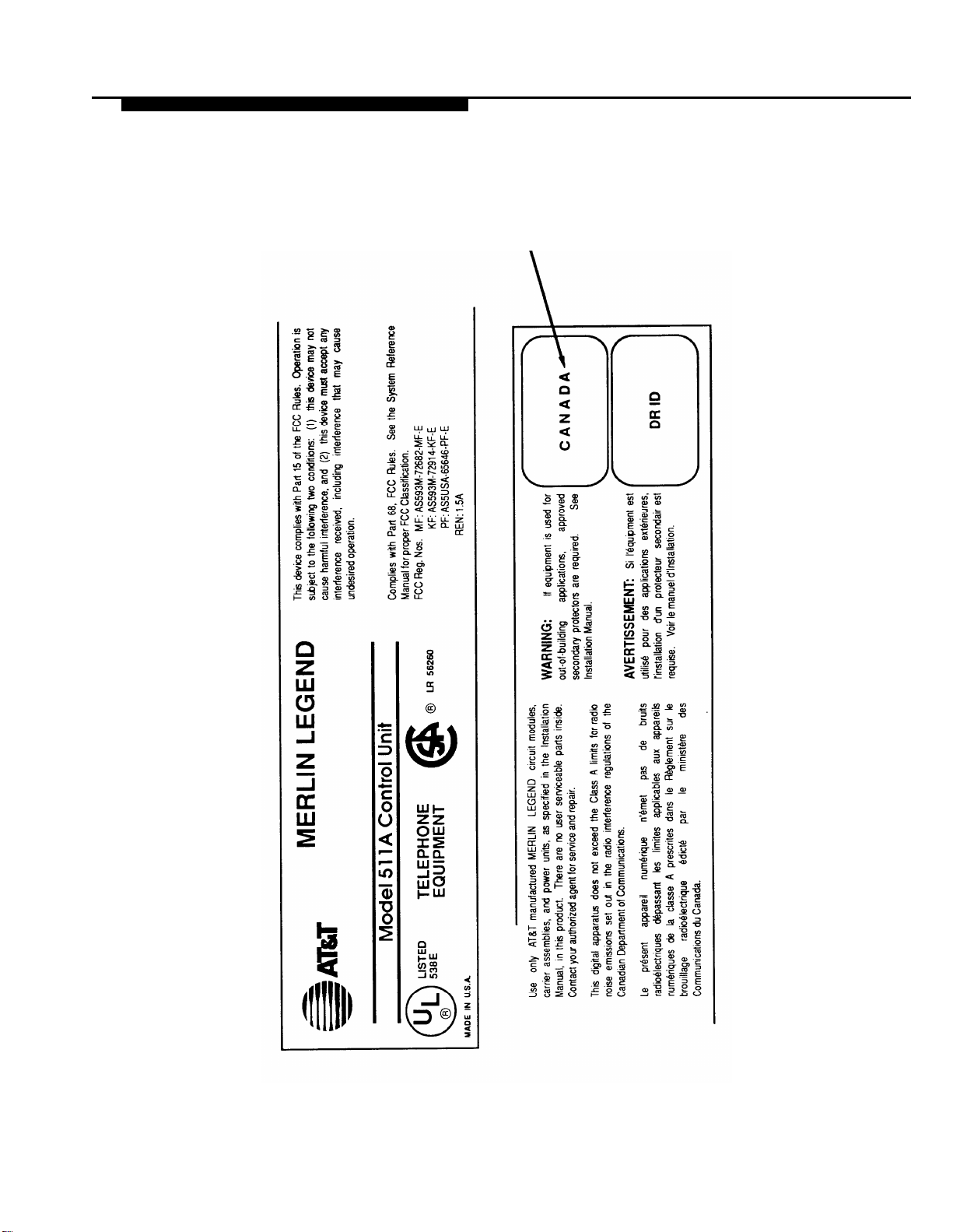
Customer Support Information
MERLIN LEGEND D.O.C.
Location Label Placement
Ministère des Communications
du Canada emplacement de
I’étiquette
xvi
Customer Support Information
Page 19

Customer Support Information
Security of Your System—Preventing Toll Fraud
As a customer of a new telephone system, you should be aware that there
exists an increasing problem of telephone toll fraud. Telephone toll fraud can
occur in many forms, despite the numerous efforts of telephone companies and
telephone equipment manufacturers to control it. Some individuals use
electronic devices to prevent or falsify records of these calls. Others charge
calls to someone else’s number by illegally using lost or stolen calling cards,
billing innocent parties, clipping on to someone else’s line, and breaking into
someone else’s telephone equipment physically or electronically. In certain
instances, unauthorized individuals make connections to the telephone network
through the use of remote access features.
The Remote Access feature of your system, if you choose to use it, permits offpremises callers to access the system from a remote telephone by using an 800
number or a
acknowledgement signaling the user to key in his or her authorization code,
which is selected and administered by the system manager. After the
authorization code is accepted, the system returns dial tone to the user. If you
do not program specific egress restrictions, the user
call normally dialed
premises network call is originated at, and will be billed from the system
location.
7- or 10-digit telephone number. The system returns an
from a telephone associated with the system. Such an off-
will be able to place any
The Remote Access feature, as designed, helps the customer, through proper
administration, to minimize the ability of unauthorized persons to gain access to
the network. Most commonly, phone numbers and codes are compromised
when overheard in a public location, through theft of a wallet or purse
containing access information, or through carelessness (writing codes on a
piece of paper and improperly discarding it). Additionally, hackers may use a
computer to dial an access code and then publish the information to other
hackers. Enormous charges can be run up quickly. It is the customer’s
responsibility to take the appropriate steps to properly implement the features,
evaluate and administer the various restriction levels, protect access codes,
and distribute access codes only to individuals who have been fully advised of
the sensitive nature of the access information.
Common carriers are required by law to collect their tariffed charges. While
these charges are fraudulent charges made by persons with criminal intent,
applicable tariffs state that the customer of record is responsible for payment of
all long-distance or other network charges. AT&T cannot be responsible for
such charges and will not make any allowance or give any credit for charges
that result from unauthorized access.
To minimize the risk of unauthorized access to your communications system:
■ Use a nonpublished Remote Access number.
■ Assign authorization codes randomly to users on a need-to-have basis,
keeping a log of ALL authorized users and assigning one code to one
person.
Customer Support Information
xvii
Page 20

Customer Support Information
Use random sequence authorization codes, which are less likely to be
easily broken.
Deactivate all unassigned codes promptly.
Ensure that Remote Access users are aware of their responsibility to
keep the telephone number and any authorization codes secure.
When possible, restrict the off-network capability of off-premises callers,
via use of Call Restrictions and Disallowed List capabilities.
When possible, block out-of-hours calling.
Frequently monitor system call detail reports for quicker detection of any
unauthorized or abnormal calling patterns.
Limit Remote Call Forward to persons on a need-to-have basis.
Limited Warranty and Limitation of Liability
AT&T warrants to you, the customer, that your MERLIN LEGEND
Communications System will be in good working order on the date AT&T or its
authorized reseller delivers or installs the system, whichever is later (“Warranty
Date”). If you notify AT&T or its authorized reseller within one year of the
Warranty Date that your system is not in good working order, AT&T will without
charge to you repair or replace, at its option, the system components that are
not in good working order. Repair or replacement parts may be new or
refurbished and will be provided on an exchange basis. If AT&T determines
that your system cannot be repaired or replaced, AT&T will remove the system
and, at your option, refund the purchase price of your system, or apply the
purchase price towards the purchase of another AT&T system.
If you purchased your system directly from AT&T, AT&T will perform warranty
repair in accordance with the terms and conditions of the specific type of AT&T
maintenance coverage you selected. If you purchased your system from an
AT&T-authorized reseller, contact your reseller for the details of the
maintenance plan applicable to your system.
This AT&T limited warranty covers damage to the system caused by power
surges, including power surges due to lightning.
The following will not be deemed to impair the good working order of the
system, and AT&T will not be responsible under the limited warranty for
damages resulting from
xviii
failure to follow AT&T’s installation, operation, or maintenance
instructions
unauthorized system modification, movement, or alteration
unauthorized use of common carrier communication services accessed
through the system
abuse, misuse, or negligent acts or omissions of the customer and
persons under the customer’s control
acts of third parties and acts of God
AT&T’S OBLIGATION TO REPAIR, REPLACE, OR REFUND AS SET FORTH
ABOVE IS YOUR EXCLUSIVE REMEDY.
EXCEPT AS SPECIFICALLY SET FORTH ABOVE, AT&T, ITS AFFILIATES,
SUPPLIERS, AND AUTHORIZED RESELLERS MAKE NO WARRANTIES,
EXPRESS OR IMPLIED, AND SPECIFICALLY DISCLAIM ANY WARRANTIES OF
MERCHANTABILITY OR FITNESS FOR A PARTICULAR PURPOSE.
Customer Support Information
Page 21

Customer Support Information
Limitation of Liability
EXCEPT FOR PERSONAL INJURY, DIRECT DAMAGES TO TANGIBLE
PERSONAL PROPERTY PROXIMATELY CAUSED BY AT&T, AND LIABILITY
OTHERWISE EXPRESSLY ASSUMED IN A WRITTEN AGREEMENT SIGNED BY
AT&T, THE LIABILITY OF AT&T, ITS AFFILIATES, SUPPLIERS, AND
AUTHORIZED RESELLERS FOR ANY CLAIMS, LOSSES, DAMAGES, OR
EXPENSES FROM ANY CAUSE WHATSOEVER (INCLUDING ACTS OR
OMISSIONS OF THIRD PARTIES), REGARDLESS OF THE FORM OF ACTION,
WHETHER IN CONTRACT, TORT OR OTHERWISE, SHALL NOT EXCEED AN
AMOUNT EQUAL TO THE LESSER OF THE DIRECT DAMAGES PROVEN OR
THE PURCHASE PRICE OF THE SYSTEM. IN NO EVENT SHALL AT&T OR ITS
AFFILIATES, SUPPLIERS, OR AUTHORIZED RESELLERS BE LIABLE FOR
INCIDENTAL, RELIANCE, CONSEQUENTLY, OR ANY OTHER INDIRECT LOSS
OR DAMAGE (INCLUDING LOST PROFITS OR REVENUES) INCURRED IN
CONNECTION WITH THE SYSTEM. THIS LIMITATION OF LIABILITY SHALL
SURVIVE FAILURE OF THE EXCLUSIVE REMEDY SET FORTH IN THE LIMITED
WARRANTY ABOVE.
Voice Mail Systems
Your Voice Mail system permits callers to leave verbal messages for system
users or gain access to the back-up position in an emergency as well as create
and distribute voice messages among system users.
The Voice Mail system, through proper administration, can help you reduce the
risk of unauthorized persons gaining access to the network. However, phone
numbers and authorization codes can be compromised when overheard in a
public location, are lost through theft of a wallet or purse containing access
information, or through carelessness (writing codes on a piece of paper and
improperly discarding them). Additionally, hackers may use a computer to dial
an access code and then publish the information to other hackers. Substantial
charges can accumulate quickly. It is your responsibility to take appropriate
steps to implement the features properly, evaluate and administer the various
restriction levels, protect and carefully distribute access codes.
Under applicable tariffs, you will be responsible for payment of toll charges.
AT&T cannot be responsible for such charges and will not make any allowance
or give any credit resulting from unauthorized access.
To reduce the risk of unauthorized access through your Voice Mail system,
please observe the following procedures:
Employees who have voice mailboxes should be required to use the
passwords to protect their mailboxes.
— Have them use random sequence passwords.
— Impress upon them the importance of keeping their passwords a
secret.
— Encourage them to change their passwords regularly.
The administrator should remove any unneeded voice mailboxes from
the system immediately.
Customer Support Information
xix
Page 22

Customer Support Information
AUDIX Voice Power™ has the ability to limit transfers to subscribers only.
You are strongly urged to limit transfers in this manner.
Use the PBX or Key system administration capability to do the following:
—
Block direct access to outgoing lines and force the use of
account codes/authorization codes.
— Disallow trunk-to-trunk transfer unless required.
— Assign toll restriction levels to all AUDIX Voice Power ports.
—
If you do not need to use the Outcalling feature, completely
restrict the outward calling capability of the AUDIX Voice Power
ports.
Monitor SMDR reports or Call Accounting System reports for outgoing
calls that might be originated by AUDIX Voice Power ports.
Remote Administration and Maintenance
The Remote Administration and Maintenance feature of your
telecommunications system, if you choose to use it, permits users to change the
system features and capabilities from a remote location.
The Remote Administration and Maintenance feature, through proper
administration, can help you reduce the risk of unauthorized persons gaining
access to the network. However, telephone numbers and authorization codes
can be compromised when overheard in a public location, are lost through theft
of a wallet or purse containing access information, or through carelessness
(writing codes on a piece of paper and improperly discarding them).
Additionally, hackers may use a computer to dial an access code and then
publish the information to other hackers. Substantial charges can accumulate
quickly. It is your responsibility to take appropriate steps to implement the
features properly, evaluate and administer the various restriction levels, and
protect and carefully distribute access codes.
Under applicable tariffs, you will be responsible for payment of toll charges.
AT&T cannot be responsible for such charges and will not make any allowance
or give any credit resulting from unauthorized access.
To reduce the risk of unauthorized access through Remote Administration and
Maintenance, please observe the following procedures:
The System Administration and Maintenance capability of a PBX or Key
system is protected by a password.
— Change the default password immediately.
— Continue to change the password regularly.
— Only give the password to people who need it and impress upon
xx
Customer Support Information
them the need to keep it secret.
If anyone who knows the password leaves the company, change
the password immediately.
Page 23

Customer Support Information
If you have a special telephone line connected to your PBX or Key
system for Remote Administration and Maintenance, you should do one
of the following:
— Unplug the line when it is not being used
— Install a switch in the line to turn it off when it is not being used.
— Keep the Remote Administration and Maintenance telephone
number secret. Only give it to people who need to know it, and
impress upon them the need to keep it a secret. Do not write the
telephone number on the PBX or Key system, the connecting
equipment, or anywhere else in the system room.
If your Remote Administration and Maintenance feature requires that
someone in your office transfer the caller to the Remote Administration
and Maintenance extension, you should impress upon your employees
the importance of only transferring authorized individuals to that
extension.
Customer Support Information
xxi
Page 24

About This Book
The power and versatility of the MERLIN LEGEND™ Communications System is
due in part to its many options and features. These options and features have
been recorded on system planning forms and initially programmed at the time of
installation. Changes in use patterns, additional equipment, or a change in
operating mode may necessitate additional system programming. This book is
a reference, containing all the programming procedures you need to enable
your system to function at peak efficiency.
Intended Audience
This book is intended for system manager—people who plan, program,
maintain, and manage the communications system. It is also intended for
qualified support personnel who are responsible for installation and initial
system programming.
Conventions
The following typographical conventions are used in this book:
Bold type is used for telephone buttons.
Italic type is used for emphasis and as a substitute for information for
which you must supply a specific value.
Press Drop to delete the current entry.
Specify extension: dial/type nnnn.
Specify slot and port: dial/type sspp.
Conventions 1
Page 25

About This Book
Contstant width type
screens or on a PC screen.
Select Sys Program.
Bold constant width type indicates information that you enter
exactly as shown.
Type
Keys on the PC are shown in boxes.
Press
When two keys are to be pressed at the same time, the keys are
connected by a plus sign.
Press
Product Safety Labels
Throughout this book, hazardous situations are indicated by an exclamation
point inside a triangle, along with the word caution or warning.
WARNING:
Warning indicates the presence of a hazard that could cause death or
severe personal injury if the hazard is not avoided.
install;
dial
[ F7 ]
[ ALT ] + [ P ]
is used for information on telephone display
#55.
CAUTION
Caution indicates the presence of a hazard that will or can cause minor
personal injury or property damage if the hazard is not avoided.
2 Product Safety Labels
Page 26

About This Book
Related Documents
Document No.
555-620-114
555-620-110
555-620-115
555-620-116
555-620-111
555-620-112
555-620-113
555-620-122
555-620-123
555-620-150
555-620-152
555-620-124
555-620-125
555-620-151
555-620-120
555-620-121
555-620-128
555-620-126
555-620-127
Title
System Documents
System Overview
Feature Reference
Equipment and Operations Reference
Pocket Reference
System Programming
System Planning
System Planning Forms
Telephone User Support
MLX- 10D™, MLX-28D™, and MLX-20L™
Display Telephones User’s Guide
MLX-10D™, MLX-28D™, and MLX-20L™
Display Telephones Quick Reference
MLX-10D Telephone Tray Cards (6 cards)
MLX-28D and MLX-20L Telephone Tray Cards (5 cards)
MLX-10™ Non-Display Telephone User's Guide
MLX-10™ Non-Display Telephone Quick Reference
MLX-10 (non-display) Telephone Tray Cards (6 cards)
Analog Multiline Telephones User’s Guide
Analog Multiline Telephones Quick Reference
MLC-5 Cordless Telephone Quick Reference
Single-Line Telephones User’s Guide
Single-Line Telephones Quick Reference
555-620-134
555-620-135
555-620-132
555-620-133
555-620-136
555-620-137
555-620-130
555-620-131
555-620-129
System Operator Support
MLX Direct-Line Consoles Operator’s Guide
MLX Direct-Line Consoles Quick Reference
Analog Direct-Line Consoles Operator’s Guide
Analog Direct-Line Consoles Quick Reference
MLX Queued Call Console Operator’s Guide
MLX Queued Call Console Quick Reference
Miscellaneous User Support
Calling Group Supervisor’s Guide
Calling Group Supervisor’s Quick Reference
Data User’s Guide
Related Documents 3
Page 27

About This Book
How to Comment on This Document
We welcome your comments, both good and bad. Please use the feedback
form on the next page to let us know how we can continue to serve you. If the
feedback form is missing, write directly to
A. Sherwood
AT&T
99 Jefferson Road
Room 2A25
Parsippany, NJ 07054
How to Comment on This Document
4
Page 28

Programming Overview
This chapter covers the information you need to know before you begin using
any of the programming procedures.
It includes:
system programming basics
how to use the system programming console
how the programming screens and keys work
how to interpret and use the programming procedures
how to enter and exit system programming
what system components require idle states for programming
new programming features introduced in Release 1.1 and 2.0.
Programming Overview 1-1
Page 29

Programming Overview
Introduction to System Programming
The Communications System offers easy-to-use, menu-driven software for
system programming. After your system is installed, you use this software to
reconfigure, update, or modify your system according your changing business
needs, such as modifying or upgrading lines, telephones, and modules
connected to your system.
Planning Forms
Before you begin to program or modify your communications system, you
should familiarize yourself with the system planning forms. Initially, system
planning forms are used to plan your communications system and program your
system during installation. After installation, they remain a source for all
programming information on your communications system database. The
information ranges from the system time and date to specific equipment
configurations and feature programming.
Each planning form is either required or optional:
■ required —
■
optional — forms needed only if the system included the features or
options on the forms.
Before you begin to program or modify your system, review the control unit
diagram on System Planning Form 1 to identify the module types installed in the
system’s control unit. Use this information to program or modify lines and trunks
and assign or reassign lines to telephones. Check the physical control unit to
verify that the modules are placed in the slots identified on the diagram and
correct the diagram on System Form 1 if there are any discrepancies” .
Before you make any changes to your system, be sure to do the following:
■ Keep your planning forms up-to-date by indicating any system
modifications or changes on the appropriate form after the change is
made.
■ Check the Feature Reference for possible feature interactions.
■
Program the system or the system component during the appropriate
idle state. See “Idle States” later in the chapter.
forms needed to program the system.
1-2
Introduction to System Programming
Page 30

Programming Overview
Types of Programming
There are three types of programming for the communications system:
System Programming
features that affect all or most system users. System programming
requires one the following:
—
an MLX-20L™ telephone connected to one of the first five ports
of the first MLX module in the control unit
— a PC with System Programming and Maintenance (SPM)
software connected to the lower RS-232 port on the processor,
with a built-in modem in the processor. The modem permits
remote programming and maintenance via the public network.
SPM emulates a system programming console on your PC.
NOTE:
If your system has the AT&T Integrated Solution II (IS II) — UNlX®
application, you have a Master Controller equipped with the UNIX
version of SPM. See Chapter 2 for more information.
Extension Programming enables individual telephone users and
system operators (except for QCC operators) to change their telephone
features to meet individual needs. For details on extension programming,
see the appropriate user and operator guides.
Centralized Telephone Programming enables the System manager to
program any feature that can be programmed by individual telephone
users or system operators. Centralized Telephone Programming can be
done on the programming console or on a PC with the SPM software.
For details on Centralized Telephone Programming, see Chapter 4.
enables the System manager to program
—
Introduction to System Programming 1-3
Page 31

Programming Overview
System Programming Console
The system programming console is an MLX-20L telephone connected to the
system programming jack. When you enter system programming on a new
system for the first time, the console must be connected to the first jack on the
first 008 MLX module or 408 GS/LS-MLX module (Release 2.0 and later
versions). This jack is factory set as the system programming jack and as an
operator position. After you enter programming, you can change the system
programming jack to anyone of the first five jacks on the first 008 MLX module
or 408 GS/LS-MLX module (Release 2.0 and later versions). This allows you to
program without interfering with the operator’s call handling.
You can also have one or two Direct Station Selectors (DSSs) connected to the
system programming console. Each DSS adds 50 extension buttons to the
console, which facilitates assigning features to telephones.
The MLX-20L telephone with a DSS is shown in Figure 1-1.
Figure 1-1. MLX-20L Telephone
1-4 System Programming Console
Page 32

Programming Overview
Console Components
The MLX-20L console components
are the following:
Desk Stand (not shown)
An adjustable stand on the console and the DSS that
allows a 20- or 30-degree viewing angle.
Button Labeling Cards
Cards labeled with the number or feature assigned to
each line button,
Contrast Control (not shown)
A sliding control at the top of the console used to
brighten or dim the display screen.
Dedicated Feature Buttons
Eight imprinted buttons for most-used features.
Feature
for viewing the Feature screen and
selecting features.
HFAI
(Hands Free Answer on Intercom) for
answering voice-announced calls without the
handset.
Mute
for turning the speakerphone’s microphone on and off.
Speaker
for talking on a call through the speaker-
phone without lifting the handset.
Transfer
Conf
conference call.
Drop
a conference call.
Dialpad
Number pad for dialing telephone numbers.
Direct Station Selector (DSS)
A device that adds extension buttons and other inside
and outside calling buttons to the console.
Display Buttons
Four imprinted buttons and ten non-imprinted buttons
used to view the different screens and select names,
features, and options from display screen.
Display Screen
7-line by 24 character screen that shows call
information, features, prompts, date, and time.
Handset
The hand-held part of the console you pick up, talk
into, and listen from.
LEDs
(Light-Emitting Diodes) The lights on the console that
assist in checking feature status.
Line Buttons
20 buttons to make and receive calls; unlabeled
buttons are programmable for one-step feature use.
Message Light
A red light that signals a waiting message.
User Cards and Tray
A slide-out drawer with erasable cards for noting
telephone numbers and feature codes.
Volume Control
A button for adjusting the volume of the speaker,
handset, headset, and ringer.
for sending a call to another telephone.
for adding a line or extension to a
for disconnecting an extension or line from
Hold
for putting a call on hold.
The DSS components are the
following:
Covers:
Removable plastic covers to protect the
designation cards. The top cover protects the
50 DSS button labels. The lower cover fits over
the fixed feature buttons.
DSS Designation Cards
Cards for labeling the extension or feature
assigned to each button.
DSS Buttons
50 buttons used for one-touch dialing of co-
workers’ extensions to make or transfer calls.
DSS buttons are also used to page co-workers
over speakerphones, to park calls, and to
handle outside calls. The console can be
configured with two DSSs to provide 3 “pages”
of 100 extensions each.
Fixed Buttons
Ten additional buttons, including Message
Status and three Page buttons. The six
remaining buttons on the first DSS are not
used. If a second DSS is connected to the
console, the 10 buttons at the bottom of the
second DSS are not used.
Fixed Message Status Button
A button used with the fixed Page buttons to
see which telephones have message lights on.
Fixed Page Buttons Three buttons used to
select the “pages” of extensions the 50 DSS
buttons represent.
LEDs
(Light-Emitting Diodes) The lights on the DSS
that assist in checking feature status.
System Programming Console 1-5
Page 33

Programming Overview
Console Buttons
System programming can be done using the console’s 14 display-area buttons.
These buttons are arranged in two columns of seven buttons, as shown in
Figure 1-2.
Figure 1-2. Display Buttons
The top two buttons in each column have the same labels and functions
regardless of the display. Table 1-1 describes these functions.
Table 1-1. Display Button Descriptions
Button
Home
Menu
More
Inspct
The five unlabeled buttons on each side of the screen are used to select screen
commands or items on a menu screen. The functions of these buttons vary,
based on the option you select.
If you are using SPM for system programming, the simulated MLX-20L console
screen on your PC screen shows the functions keys that correspond with the
console screen selections. This manual indicates a function key in a box. For
example, to save your entry, you select Enter or press
details on using function keys and other information on SPM, see Chapter 2.
Function
Return to normal call-handling mode after you finish programming. This button
displays the Home screen.
Display the Main Menu shown in Figure 1-2.
Display more menu items when a menu is continued on more than one screen
(indicated by a “>”).
(Inspect) View a list of lines or telephones on which a feature is programmed.
[ F10 ] on your PC
1-6
System Programming Console
Page 34

Programming Overview
Console Overlay
The programmable lines and buttons are on the main part of the console. There
are 20 phvsical buttons on the console itself but you can use the overlay to
program up to 34 lines. Some of the unlabeled buttons on the lower part of the
console may also be used for programming features. You can also use the
dialpad for entering feature and programming codes.
Figure 1-3 illustrates the system console overlay.
Figure 1-3. Console Overlay
Appendix D shows the button diagrams for the telephones used in the
communications system. Refer to this appendix when programming buttons for
other telephones.
System Programming Console 1-7
Page 35

Programming Overview
Console and DSS Lights
The red and green lights (LEDs) next to each of the 20 line and feature buttons
show the status of line features.
Console
The LEDs next to each button on the console are on or off, depending on
whether the line is programmed with a feature. The feature being programmed
determines whether the red or green LED is used to indicate feature status. The
programming procedures specify which LED is used to verify feature status.
DSS
The lights on the DSS — if the console has one — show the status of features
programmed onto the telephones that correspond to the lights. When you
select a feature from a menu, the red LED next to the DSS button is on, off, or
flashing depending on whether the feature is programmed on the
corresponding telephone. For example, when you select Toll Restrict from
the Restrictions menu under Extensions, the red LED will be on next to the DSS
button for each toll restricted telephone. Appendix B provides tables showing
the default LED status for system features.
1-8 System Programming Console
Page 36

Programming Overview
Programming Procedures
The programming procedures provide step-by-step instructions for
programming the communications system using system programming.
Procedure Organization
The procedures in Chapter 3 are arranged in logical groupings. This means
that all the procedures for programming one aspect of the system are grouped
under one heading. For example, if you want to assign network services for
PRI, you would refer to the “PRI” section for that procedure. Chapter 3 provides
both an alphabetical listing of all procedures and a listing by section. You can
also use the Menu Hierarchy in Appendix A to find the menu path for a function.
General Programming Information
Each procedure begins with a general description of the feature, then provides
a summary of programming information. This information includes the following:
Programmable by-indicates who has system permission to use the
procedure
Mode — specifies which system mode supports the procedure
Idle condition—specifies the idle state required before the procedure
can be performed
Planning form —
the procedure
Factory setting-shows the default settings, if any, for equipment or
features affected by the procedure
Valid entries — specifies the characters or numbers accepted during data
entry
Inspect — specifies whether or not the feature status can be verified using
the Inspect feature
Copy option — indicates whether or not the feature programmed with
procedure can be copied to another system component
Console Procedure — provides a summary of the procedure steps if using
the system console
PC Procedure — provides a summary of the procedure steps if using
SPM
indicates which planning forms provide information for
Programming Procedures 1-9
Page 37

Programming Overview
Programming Screens
There are three types of system programming screens:
Information screens - to see what is currently programmed on the
system
Menu selection screens - to select options from a menu
Data entry screens - to enter values or to identify a specific extension or
line/trunk you want to program
Figure 1-4 shows an example of an information screen. When you select
SYS
Progam from the main menu screen (Figure 1-2), the screen shown in Figure
1-4 displays system set up information. (Your system information displays in
place of the x’s.)
System Set–up
Review and Exit
Figure 1-4.
Size: xxxx
Type:
Operator: xxxx xxxx xxxx
xxxx xxxx xxxx xxxx xxxx
Exit
Information Screen
xxxx
You cannot make changes on an information screen. Select Exit ( [ F5 ] on the
PC) to continue to the next screen in the procedure.
An example of a menu selection screen is shown in Figure 1-5.
Screen Title
Instruction
System Programming:
Make a selection
System
SysRenumber
Operator
LinesTrunks
Exit
Extensions
Options
Tables
AuxEquip
NightSrvce
>
Options
—
1-10
Figure 1-5. Menu Selection Screen
The first line of text on all screens is the screen title, followed on the second line
by a system prompt or direction about how to proceed. The remaining lines of
text vary according to the screen.
While a menu selection screen prompts you to select one of the available
options, a data entry screen prompts you to enter specific data for the
procedure, as shown in Figure 1-6.
Programming Procedures
Page 38

Programming Overview
Figure 1-6. Data Entry Screen
If any data is currently programmed for the feature, it displays on the screen.
Some screens also show data entered on a previous screen, such as an
extension or trunk number.
A data entry screen may also offer menu selections—instead of entering data
from the dialpad, you select options on the screen, such as Yes or No, to enable
or disable a feature. These options are selected by pressing the button next to
the option. Your selection is highlighted. To program or save that selection, you
press the button next to Enter
Verifying Data Entry
You can use the Inspect feature to verify or check the entries you save. For
example, Figure 1-7 shows a data entry screen with the first of two required
extension numbers needed to assign analog voice and data.
Option Selected
Prompt
Data Entry Area
[ F10 ]
Assign Lines/Trunks:
Enter extension
Backspace
Exit
on the PC.
Enter
Data Voice/Data
Enter voice/data pair
Extension Entered —
7108
Backspace
Exit
Delete
Enter
Figure 1-7. Inspect Example
After 7108 is entered and saved, the system automatically assigns the next
sequential station jack number. This station jack pair does not display on the
data entry screen; however, if you press
Inspct,
the pair displays as shown on
the Inspect screen in Figure 1-8.
Programming Procedures
1-11
Page 39

Programming Overview
Figure 1-8. Inspect Example: Inspect Screen
You can select Exit ( [ F5 ] on the PC) to return to the previous screen. The
Inspect feature also enables you to check a value currently programmed for a
feature. This is helpful when you are changing or modifying features. You can
also use Inspect when programming sequential extensions or lines to verify the
last number programmed. See Feature Reference for details.
Using Procedures
The procedures are numeric steps. Each step requires an action on the console
or PC. Some steps offer menu selections that may not be part of a required
step and some steps present two ways to perform the procedure. This is called
branching. To accommodate branching, a procedure offers a choice of steps to
follow at the branching point. For example, the menu screen shown in Figure
1-9 provides three selections for network services. The procedure instructions
break the step that follows into three branches to accommodate the three menu
selections:
Inspect Data Displayed —
Voice/Data Pairs:
7108 7109
Exit
>
1-12
Network Services:
Make a selection
AT&T Toll
Local
Mist
Exit
For AT&T Toll, go to Step 6a.
For Local, go to Step 6b.
For Mist, go to Step 6c.
Figure 1-9. Procedure Branching for Menu Selections
Branching within procedures is also used when you can select between
programming a single item or a block of items, such as a single line or a block
of lines, as shown in Figure 1-10.
Programming Procedures
Page 40

Programming Overview
Copy Lines
Make a selection
Single
Block
Exit
For a single line, go to Step 5a.
For a block of lines, go to Step 5b.
Figure 1-10. Procedure Branching for Single ad Block Selections
When you complete the branch step, you can continue on to the next numerical
step. In many cases, you can also select Exit (
menu where the branch began.
Programming a Single Item Using Entry Mode
[ F5 ] on the PC) to return to the
A screen may offer a selection between a block of items (such as block of lines
or trunks) and Entry Mode, as shown in Figure 1-11:
Extension xxxx
Assign lines/trunks
Lines 01-20
Lines 21-40 Entry Mode
Lines 41-60
Lines 61-80
Exit
Figure 1-11. Entry Mode
To program one of the lines within any of the blocks, you select Entry Mode
[ F6 ] on the PC). The procedure uses branching to provide the steps needed
(
to accommodate your selection. Once you begin entry mode, you provide
entries as in any other data entry screen.
Programming Procedures
1-13
Page 41

Programming Overview
Saving Entries and Moving Among Screens
At the bottom of each screen, there are one or more keys that enable you to
change your entry, save your entry, or return to a previous screen.
Combinations of these keys display within each programming option. These
keys are shown in Figure 1-12.
QCC Priority x:
Enter line/trunk number
xxx
Backspace Next
Exit Enter
Figure 1-12. Screen Keys
You use these keys in the folIowing ways:
Change your entry. You can correct your entry by selecting Backspace
[ F4 ] on the PC). Each time you press the key, the screen cursor
(
moves backwards to erase one character at a time.
Save your entry. Typically, you complete a procedure by selecting
Enter (
must select Exit (
Delete a current entry. You can delete (or remove) a current entry by
selecting Delete (
Program sequentially numbered items. If you are programming a
group of sequentially numbered extensions or lines/trunks, you may have
the option of selecting Next (
and automatically provides the number of the next extension or trunk in
the sequence. Typically, you remain at the same screen for as long as
you select Next.
the procedure.
[ F10 ] on the PC) to save the information. Occasionally, you
[ F5 ] on the PC) and go back to the previous screen.
[ F8 ] on the PC).
[ F9 ] on the PC). This saves your entry
In a few cases, you may return to an earlier screen in
Delete
1-14
Return to the previous screen. When you have completed a
procedure, selecting Exit (
the menu hierarchy. (Appendix A provides a reference to the entire
system programming menu hierarchy.)
Exit a screen without changes. In most cases, to exit from a screen
without making any changes: select Exit (press
noted as part of a procedure.
When you complete a procedure, you can select select Exit or press
a few cases, you return to the System Programming menu. In most cases, you
return to an intermediate step within the procedure. You can then select one of
the options shown on the screen and continue programming, or you can
continue to press Exit until you return to the System programming menu.
Programming Procedures
[ F5 ] on the PC) takes you up one screen in
[ F5 ] ). Exceptions are
[ F5 ] In
Page 42

Programming Overview
Entering System Programming
The instructions for entering system programming are given below in the same
table format used for the programming instructions in Chapter 3:
the step in the procedure (Step)
the current screen display and the action you take (Display/Instructions)
the selection from the menu (On the console)
the function key to press on the PC (On the PC)
Typically, the results of each step are shown in the screen in the next step
Step
Display/Instructions
12/24 11:30
Anne
Andre
Jose
Show Number Next Page
Kim
Jorge
Sarah
Display Main Menu
MENU MODE :
Press HOME to Exit
Directory
Messages
Posted Msg
Alarm Clock
Timer
Select Feature
Sys Program
Maintenance
Ext Program
Select System Programming.
Note: Ext Program does not
display if programming console
is a QCC.
On the console
Press
Menu.
Select Sys Program.
On the PC
Press [ F2 ].
Press
[ F8 ].
Entering System Programming
1-15
Page 43

Programming Overview
Step
3
4
Display/Instructions
Display System Programming
menu. (Your system set-up
information displays in place of
the x’s shown in screen.)
Note:
The System Set-up
screen is an information screen.
The information shows the
system size (small or large),
type (mode), and Operator
(position extension numbers).
The size and type are
programmed during installation.
The operator positions that
display will change as you add
and remove operator
extensions from the system.
On the console
Select Exit.
On the PC
Press
[ F5 ]
1-16
Make a selection.
Note: A > on the screen means
that the menu has more than
one screen. To see the
additional screens, press More.
Entering System Programming
Press the button next to
your selection.
Press the function key
for your selection.
Page 44

Programming Overview
System Programming Menu Options
Table 1-2 lists the System Programming options that display on the System
Programming menu.
Table 1-2. System Programming Menu Options
Option
—
System
SysRenumber
Operator
LinesTrunks
Extensions
Options
Tables
AuxEquip
NightSrvce
Labeling
Description
Set system operating conditions.
Select the system numbering plan and/or reassign extension
numbers with 1- to 4-digit numbers that are more appropriate or
convenient for your company.
Assign or remove operator positions and program operator
features (such as Operator Hold Timer or QCC options).
Program line/trunk options.
Program features for telephones (such as restrictions, line
assignments).
Program system-wide features (such as Transfer Return, Delay
Ring).
Program feature that require entering information in a table
(such as Allowed Lists, Disallowed Lists).
Program auxiliary equipment connected to the system (such as
loudspeaker paging, fax).
Program Night Service Features.
Program the labels shown on display telephones (such as
System Directory, Posted Messages).
Data
Print
Cntrl Prog
Language
Exit
Specify telephones that need simultaneous voice and data
capability.
Print system programming reports (such as system
configuration, extension assignments).
Do centralized telephone programming (assign features to
specific buttons on telephones).
Select the language that your console uses to display text on
the screens. Selections are English (default), French, and
Spanish.
Exit system programming.
Entering System Programming
1-17
Page 45

Programming Overview
Exiting System Programming
Use the following step to return to the System Programming menu, the main
menu, or to the Home screen from within a programming screen.
Display/Instructions
Any Screen
■ Return to previous menu
■ Return to main menu
■ Return to normal call handling Press Home.
On the console
Press
Exit.
Press
Menu.
On the PC
Press
[ F5 ].
Press
End.
Press
Home.
1-18
Exiting System Programming
Page 46

Programming Overview
Idle States
Some programming procedures can be started only when the entire system, or
some part of the system (such as a trunk or an extension), is idle, that is, not in
use. Some procedures require that a trunk or extension be idle only at the
instant of programming. Lengthy procedures require the system, trunk, or
extension be forced into remaining idle until programming is completed. These
procedures wait for the system or trunk or extension to become idle and then
prevent the initiation of any new calls—a condition called forced idle,
If a procedure requires an idle condition, do the programming outside of normal
business hours.
If a procedure requires an idle system and the system is busy when you begin,
you see the screen shown in Figure 1-13:
Figure 1-13. System Busy Screen
When the system is no longer busy, the screen changes to the appropriate
programming screen.
System Forced Idle
When the entire system is forced idle, no calls can be made or received. The
following procedures can be done only when the entire system (all lines and
telephones) is idle:
■ select system mode
■ identify system operator positions
■ renumber system
■ renumber modules
■ identify telephones with voice signal pairs for Voice Announce to Busy
feature
■
identify telephones needing Simultaneous Voice and Data feature
Idle States
1-19
Page 47

Programming Overview
■
restore system programming information
■ identify Music-on-Hold jack
When the system is forced idle, all multiline telephone users hear a signal,
indicating that the telephone cannot be used. On a display telephone, the
message
appears. Single-line telephones do not get a dial tone.
Line or Trunk Idle
The following procedures can be done only when the line or trunk being
programmed is idle. Since these procedure require the line or trunk to be idle
only at the instant of programming, the line or trunk is not forced idle as
described above.
■ identify loudspeaker paging line jack
■ assign trunks to pools
■ specify incoming or outgoing DID or tie-trunk type
■ specify tie-trunk direction
■ specify tie-trunk E&M signal
Extension Forced Idle
When a telephone or data terminal is forced idle, no calls can be made or
received on that telephone or data terminal. The following procedures can be
started only when the telephone or data terminal being programmed is idle.
Wait :
System Busy
1-20
■ assign call restrictions
■ assign pool dial-out restrictions
■ copy telephone assignments
■ assign lines, trunks, or pools to extensions
■ assign labels to a Personal Directory
■ use centralized telephone programming
When the telephone is forced idle, a multiline telephone user hears a signal,
indicating that the telephone cannot be used. On a display telephone, the
message
Wait :
System Busy
appears. Single-line telephone user does not get a dial tone.
Idle States
Page 48

Programming Overview
100D Module Idle
The following can be done only when the 100D Module is idle:
■ specify board type
■ specify frame format
■ specify board signaling format
■ specify board suppression format
■ specify board facility compensation
Forced Idle Reminder Tones
Forced idle reminder tones are provided in the following situations:
■ At the telephone, to remind an extension that the system or the extension
is in the forced idle state.
■ At the programming console or SPM, to remind the system manager that
the system or at least one extension is in the forced idle state because of
administrative activity.
This tone is a high-low “doorphone” tone (400 ms of 667 Hz tone
followed by 400 ms of 571 Hz tone).
In a Release 1.1 or Release 2.0 system, all three tones occur every 20 seconds.
You can adjust the volume of these tones with the volume control.
Idle States
1-21
Page 49

Programming Overview
Product Enhancements
Several enhancements were implemented for System Release 1.1 and 2.0. This
section briefly describes these enhancements and new features. For details on
each enhancement, see Feature Reference and Equipment and Operations
Reference.
Procedures covering these enhancements are included in this manual. System
planning for the enhancements is covered in System Planning.
Release 1.1 Enhancements
Release 1.1 includes all Release 1.0 functionality plus the following
enhancements:
■ Language selection — allows the system to be programmed for prompts,
menus, and messages on MLX display telephones to appear in English,
French, or Spanish. Each of the following can also be programmed for
any of these languages, independent of the system language:
— Individual extensions with MLX telephones
— System programming reports
— SMDR report headers
■ 8102 and 8110 analog voice telephones
Release 2.0 Enhancements
Release 2.0 includes all Release 1.1 functionality plus the following
enhancements:
■
Programming Enhancements
—
Extension Copy feature
allowing the use of any extension as a template for programming
another extension or block of extensions through centralized
programming.
—
Integrated Administration — provides a single interface through
Integrated Solution Ill (IS-III) for programming entries common to
the system and AUDIX Voice Power™/FAX Attendant System™.
■
System Operational Enhancements
—
Coverage VMS feature
going to voice mail. The feature is programmed extension-byextension, either through extension programming or through
centralized programming.
— reduces programming time by
— prevents incoming external calls from
1-22
Product Enhancements
Page 50

Programming Overview
—
Calling Group as Night Service Group Assignment
Night Service group to be programmed to include a Calling
Group as a member.
—
Direct Inward Dialing (DID) trunk emulation on T1 facility —
provides 24 DID channels on a single DS1 trunk interface,
instead of requiring 24 separate physical trunks.
■ 408 GS/LS-MLX module — combines four ports for ground-start or loop-
start trunks and eight ports for MLX telephones on a single module in the
control unit.
■ Primary Rate Interface (PRI) enhancements — provide the following:
— Connectivity to the 5ESS® Generic 6
—
multiple incoming calls to directory number
— Call-by-Call Service selection
—
Station ID (SID) as Calling Party Number for Automatic Number
ID (ANI)
— allows a
■ Call type for Automatic Route Selection (ARS) subpatterns — voice,
data, or both
Product Enhancements
1-23
Page 51

Programming with SPM
This chapter describes the SPM software package. It explains:
■ how to use SPM displays and function keys
■ how to program in surrogate mode
2
■ how to use the main menu and SPM Help
■ how to establish local and remote PC connections
■ how to program the communications system remotely
■ how to backup and restore system programming information
■ how to convert system programming information (part of the upgrade
procedure)
■ how to install your communications system and upgrade your system to
a newer release
SPM runs on a DOS-based PC or on a UNIX® system platform with Integrated
Solution II or Integrated Solution Ill (lS-II/III). It is available on a 3½-inch
diskette. The DOS version is also available on a 5¼-inch diskette. This software
can be used directly from the floppies on a DOS machine; however, if your PC
has a hard disk, you should install SPM on the hard disk.
This chapter also describes programming on a PC with a DOS operating
system. If your system has the lS-II/-lll application, you have a Master
Controller equipped with the UNIX system version of SPM. For information
about accessing SPM from the lS-II/III application, refer to the following books:
■ Integrated Solution Ill System Manager’s Guide, Order No. 555-601-010
■ Integrated Solution Ill Installation and Maintenance Guide, Order No.
555-601-011
Programming with SPM 2-1
Page 52

Programming with SPM
■ Integrated Solution II System Manager’s Guide, Order No. 555-600-726
■ Integrated Solution II Installation and Maintenance Guide, Order No.
555-600-720
Introduction to SPM
Figure 2-1 illustrates the SPM display.
2-2
Figure 2-1. The SPM Display
SPM screens simulate the system programming console. Each SPM screen
includes a 7-line by 24-character console simulation window that corresponds
to the display area of the MLX-20L telephone. To the right and left of this
console simulation window are columns, listing the keys that correspond to
similarly located buttons on the MLX-20L telephone. If you are working with
Version 2.00 or higher (2.xx),
screen, as shown in Figure 2-1.
The 10 function keys, identified on the screen as
to select screen options. When a screen offers you several choices, press the
function key identified by the label next to your choice. (If you were
programming on the console, you would press the telephone button next to your
choice. )
Introduction to SPM
V2 appears in the upper left-hand corner of the
[ F1 ]
through
[ F10 ],
are used
Page 53

Programming with SPM
Below the console simulation window are 20 simulated line buttons. Using
[ PgDn ] (Inspect), you can determine the status of each line and which features
are programmed on each line by the letter that appears next to the line number.
R and G represent the ON state of the red and green LEDs on the system
programming console.
The 20 line buttons can be selected by using the arrow keys to position the
cursor on the appropriate key. For example, if a line, trunk, or pool is assigned
to a line button, you see G next to that button. If a line, trunk, or pool is not
assigned to a line button, you see neither G nor R. lf a trunk is assigned to a
pool, you see an
A list of labels on the right side of the screen shows key combinations that
correspond to buttons on the MLX-20L telephone
Table 2-1 describes the function of PC keys within SPM.
Table 2-1. Function of PC Keys in SPM
R.
(Alt + P, Ctrl + F8,
etc.).
PC Key
[ Home ]
[ End ]
[ PgUp ]
[ PgDn ]
[ Alt ] + [ P ]
[ Alt ] + [ F ]
[ Alt ] + [ C ]
Console
Home
Menu
More
Inspct
Drop
Conf
N/A
SPM Function
Quit: Exit from SPM and return to the
DOS prompt when you have finished
system programming. If you are using
a modem, the call is disconnected.
Return to the SPM Main Menu.
Display more menu items (when there is
an additional screen and the > symbol
appears next to the key).
Show the current information that has
been programmed for a feature or
button.
Enter a stop in a speed dialing
sequence.
This combination also deletes an entry
in a field in any screen except one in
which you are entering a speed dialing
sequence.
Flash: Enter a switchhook flash in a
speed dialing sequence.
TopSP: Return to the top of the System
Programming menu.
[ Alt ] + [ H ]
Hold
Pause: Enter a pause in a speed
dialing sequence.
Continued on next page
Introduction to SPM 2-3
Page 54

Programming with SPM
Table 2-1. - Continued
PC Key
[ Alt ] + [ U ]
[ Ctrl ] + [ F1 ]
[ Ctrl ] + [ F5 ]
[ Ctrl ] + [ F8 ]
[ Ctrl ] + [ F9 ]
[ ↵ ]
[ Backspace ]
Console
N/A Convert: Convert a backup file from an
N/A
SPM Function
earlier release to Release 2.0 format.
Help: Display a help screen about SPM
operations. To exit from Help, press
[ End ].
N/A
N/A
N/A
Enter
Backspace
Reset: Reset the communications port.
For example, if the information on the
screen is garbled, try exiting from and
then recentering the screen. If the
screen remains garbled, use
[ F5 ]
to clear the screen and return to
the SPM Welcome screen. Note that
using
[ Ctrl ] + [ F5 ]
connection.
Browse: View print reports saved with
Print Opts.
Escape to shell. To use this key
sequence, you must set DEBUG=1 in
the SPM configuration file ams. cfg.
You can then use this key sequence to
execute DOS (or UNIX system)
commands. To return to SPM, type
exit,
The
[ ↵ ]
key on your PC can be used
instead of [ F10 ] (Enter) when Enter
appears as a choice in the 7 x 24
console simulation window.
The Backspace key on your PC can be
used instead of
when it appears as a choice in the
7 x 24 console simulation window.
[ F9 ] (Backspace)
[ Ctrl ] +
drops the modem
2-4
[ Delete ]
Introduction to SPM
Delete
The
[ Delete ]
used instead of [ F8 ] (Delete) when it
appears as a choice in the 7 x 24
console simulation window.
key on your PC can be
Continued on next page
Page 55

Programming with SPM
Table 2-1. - Continued
PC Key
Console
[ ↑ ], [ ↓ ]
[ ← ], [ → ]
Surrogate Mode Programming
The purpose of surrogate mode programming is to allow system programming
by qualified service personnel at a service location rather than on-site. The
actual communications system hardware does not have to be installed; the
programmer needs only a direct connection from the PC to the processor
module. He or she then programs a system as if the appropriate modules,
trunks, and telephones were installed, following a customer’s set of planning
forms. The programmer saves the system programming on disk by performing
a system backup. The disk is then taken to a new installation and used (via the
Restore option) to provide complete system programming for a new
communications system.
You do not select surrogate mode programming; you enter it automatically,
under the following conditions:
N/A
SPM Function
The up, down, left, and right arrow keys
can be used to highlight selections in a
menu and to select the 20 line buttons
below the 7 x 24 console simulation
window.
■ The PC is connected to the lower RS-232 port on a control unit (direct
local connection).
■ Only the processor and power modules are connected.
Once you enter surrogate mode programming, the normal sequence of
procedures is as follows:
1. At the service location:
a. System Erase
b. Boards
c. System Programming
d. Backup
2. On-site:
a. Restore
While you are in surrogate mode, Pass-Thru and Password are unavailable to
other users. For more information, see “Boards” later in this chapter.
Introduction to SPM 2-5
Page 56

Programming with SPM
SPM Main Menu Options
The SPM Main Menu provides access to system programming and to the other
functions of SPM:
Sys Program
Backup*
Boards* shows you which modules (port boards) are in each slot
Print Opts* directs reports to the printer or to the PC for storage on
Monitor*
Maintenance
Restore*
Pass-Thru*
Password* allows you to change the password for remote entry into
Language
enables you to program the system,
enables you to make a backup copy of your system
programming and store it on diskette or on hard disk.
of the control unit and allows you to assign boards to
slots.
diskette or hard disk.
is restricted to use by your technical support
organization.
is restricted to use by your technical support
organization and qualified technicians.
enables you to restore your system programming from
diskette or hard disk.
(lS-II/III only) allows you to make a remote connection,
via the control unit, to an lS-II/III machine to administer
applications on the IS-II/Ill machine.
the system.
allows you to choose a language (English, French, or
Spanish) for the 7 x 24 console simulation window on
the PC. (There is also a Language selection under
YS program for setting the system language.)
S
SPM Help
*
2-6
Introduction to SPM
SPM includes help screens that you can access by pressing
You can examine the help screens with
first. Help screen, press [ Home ]; to exit from Help, press [ End ].
SPM only; not available on the MLX-20L system programming console. To be
used only by qualified service personnel.
[ PgUp ]
and
[ Ctrl ] + [ F1 ].
[ PgDn ].
To return to the
Page 57

Programming with SPM
A typical help screen is shown in Figure 2-2.
Figure 2-2. SPM Help Screen
Connecting the PC
There are three ways to connect the PC to the control unit. Choose the method
that is most useful for your installation:
■ direct local connection
■ Iocal modem connection
remote modem connection
■
These types of connections are described later in this section.
System Requirements
To use SPM to program your system, you need the SPM diskette and an AT&T
PC with version 3.3 (or a later version) of MS-DOS®. Your PC should include
the following:
■ at least 640 kbytes of RAM
Connecting the PC 2-7
Page 58

Programming with SPM
a floppy disk drive that will accommodate the SPM diskette
a monochrome or color monitor
a serial port that can use either a DB-9 or DB-25 connector
NOTE:
For a DB-9 connector, use a 9-pin to 25-pin adapter to convert the
25-pin connector to a modular connector.
an RS-232 interface cable
Also, depending on how you connect the PC to the control unit, you may need
the following:
■ either a 355AF modular adapter (if there is a male connector on the
interface cable) or a 355A modular adapter (if the connector is female)
■ a 4-pair modular cord (D8W)
In addition, the following equipment is useful:
■ a parallel printer (the PC needs a parallel port for the connection)
■ a 1200- or 2400-bps modem
NOTE:
SPM uses Interrupt 4 and I/O address 3F8 for COM1. It uses Interrupt 3
and l/O address 2F8 for COM2.
Direct Local Connection
For a direct local connection, connect the PC to the system programming jack.
This is the lower modular RS-232 jack on the processor module, as shown in
Figure 2-3. (The upper jack is reserved for the SMDR printer.) For direct local
connections, the system supports speeds of 1200 and 2400 bps. Use a direct
local connection to program in surrogate mode.
2-8 Connecting the PC
Page 59

Proaramming with SPM
Figure 2-3. Direct Local Connection
Local Modem Connection
For a local modem connection, use a modem connected to (or built into) the PC
to access the internal modem in the control unit. Connect the modem to an 012
module in the control unit, as shown in Figure 2-4. The internal modem
operates at a speed of 1200 bps.
Figure 2-4. Local Modem Connection
Remote Modem Connection
For a remote modem connection, you also use a modem connected to (or built
into) the PC to access the internal modem in the control unit; however, the
connection is a dial-up connection, as shown in Figure 2-5. The internal modem
operates at a speed of 1200 bps.
Connecting the PC 2-9
Page 60

Programming with SPM
Figure 2-5. Remote Modem Connection
NOTE:
Any modem connection overrides a direct connection unless a backup or
restore procedure is in progress via a direct local connection. When a
modem connection is attempted while any other on-site programming is in
progress, either at the system console or at a directly connected PC, the
system sends a message to the on-site programmer indicating that a
modem connection is being established, and the on-site programming .
session is terminated.
Starting SPM
The procedure for accessing SPM differs slightly, depending on whether your
PC is connected directly or by modem to the control unit. Both procedures are
described in the following sections.
2-10 Starting SPM
Page 61

Programming with SPM
With a Direct Local Connection
To access SPM when your PC is connected directly to the control unit, follow
these steps:
Step
Display
If you do not have a hard disk, insert the SPM diskette into Drive A and
switch to Drive A, if it is not already the current drive.
Start the SPM program by typing spin. The SPM Welcome screen appears
as shown in Step 3.
Instructions
Press any key. The SPM Main Menu
appears as shown in Step 4.
If the Main Menu does not appear or if the
information on the screen is garbled, press
any key again.
With a Local or Remote Modem Connection
The method you use to access SPM by modem depends on whether you are
programming on-site or from a remote location.
If you are on-site, the modem must be connected to an 012 module on the
control unit. To establish a connection to the control unit’s internal modem, dial
*10.
If you are at a remote location, do one of the following:
■ Place a call to the system on a Remote Access line, enter the barrier
code (if required), and dial the code for the internal modem (*10).
■ Place a voice call to the system on a regular line and ask the operator to
transfer you to the modem (by dialing *10), When you hear answer
tone, switch to data mode.
Select an option by pressing one of the
function keys.
You can also set up the remote connection in the other direction. Place a voice
call from the system to the remote PC running SPM and then transfer the call to
the modem.
Starting SPM
2-11
Page 62

Programming with SPM
To access SPM with a local or a remote modem connection, follow these steps:
Step
Start the SPM program by typing spm. If you prefer to program in a
language other than the current language setting for SPM, use the - l
option to the spm command (note that the option is a lowercase letter L, not
the number 1):
The SPM welcome screen appears as shown in Step 2.
3 Make a data connection to the control unit’s internal modem. The following
modem commands are for Hayes® and Hayes-compatible modems. They
may not be the commands used by your modem. Refer to your modem
user’s guide for specific information.
Display
spm - l english
spm - l french
spm - l spanish
Instructions
Press any key. (You may have to press it
several times). This brings up a blank
screen on which you can enter modem
commands.
If the PC
If the PC is in a remote location and your system has activated the
Remote Access feature, type ATDT followed by the remote access
telephone number, followed by W*10, and press
to press it more than once to get the Password prompt.)
If the PC is in a remote location and your system has not activated the
Remote Access feature, place a voice call to the system, using the main
telephone number, and have the operator transfer the call to the modem.
(The operator dials *10 to transfer the call to the modem.) To put the
modem on line, type ATH1 and press
is in the same location as the control unit, type *10.
[ ↵ ]. (You may need
[ ↵ ].
2-12
Starting SPM
Page 63

Proaramming with SPM
Step
4
5
UsingSPM
The following sections describe the use of the SPM options. Note that most of
the procedures described here are to be performed by qualified service
personnel only. Options are presented in alphabetical order for ease of
reference:
Display
Instructions
,
Type the Remote Access password. The
password you enter does not appear as
you type it. The SPM Main Menu appears
as shown in Step 5.
Select an option by pressing one of the
function keys.
Backup
Backup
Boards
Browse
Convert
Language
Maintenance
Monitor
Pass-Thru
Password
Print Options
Restore
System Programming
The Backup procedure is used by qualified service personnel to create a file of
system programming information in the \ spm\backup directory (hard disk drive
PC) or in the root directory of a diskette (floppy disk drive PC). Backing up your
system regularly is strongly recommended. If you lose system programming
information, you can restore your system quickly from a backup file.
Release 2.0 Only
If you have a backup diskette and do not know its release number, you may be
able to find this information in the backup header. Backups of Release 2.0 and
later versions of Release 1.1 contain a backup header 128 bytes long.
Using SPM
2-13
Page 64

Programming with SPM
Approximately 59 of these bytes are currently used. Bytes 55 through 59 of the
header contain the feature module identification number, as shown in Table 2-2.
(Release 1.0 and early versions of Release 1.1 do not contain this information in
readable form. )
Table 2-2. Backup Header: Feature Module Identification Number
Release No.
Size
Examples
The release number is found in the first 2 bytes of the feature module
identification number (0200 = 2.0, 0101 = 1.1).
If the backup file is compressed, you can still read the header, but you cannot
read the data area following the header. Use type backup filename to read
the header on a DOS system or cat backup filename on a UNIX system.
Note that the feature module release number, not the version number of SPM,
determines whether the backup file is compressed or uncompressed.
Release 1.0 backups are uncompressed. Release 1.1 and 2.0 backups are
compressed. Uncompressed files take longer to restore.
Before you begin a backup procedure, note the following:
2 bytes
02 00 32
01 01 02
The communications system does not have to be idle during backup;
however, station programming is blocked.
Any objects that are in a maintenance-busy state are stored in that state.
When you restore system programming, these objects are busied out,
even if they have since been released from the maintenance-busy state.
Build No.
1 byte 1 byte 1 byte
System Size
01
Mode
— Key
01
— Behind Switch
Hybrid/PBX
03—
2-14
If you plan to store your backup file on a diskette, be prepared with a
DOS-formatted diskette. (DOS formatting can be done on a UNIX
system PC or a DOS PC.)
Uncompressed backup files are 100,000 — 210,000 kbytes in size;
compressed files are about 70,000 — 85,000 kbytes.
Maintenance data (error logs and other data used by qualified service
technicians) is not saved in the backup file.
Using SPM
Page 65

Programming with SPM
Step
Display
Instructions
Select Backup by pressing [ F2 ]. The
following two screens appear.
The first screen (Make a selection
for) is an information screen. Entries you
make appear only on the second screen.
If you are using a hard disk PC, go to
Step 3.
If you are using a floppy disk PC, remove
the SPM diskette and insert a formatted
diskette. Highlight GOTO FLOPPY (use the
arrow keys) and press
[ ↵ ].
You see only one of the two narrow
screens. If you are working on a floppy
disk PC, you see the GOTO HARD DISK
screen. If you are working on a hard disk
PC, you see the
The filename shown on the
(backup.ams) is the default name for a
backup file.
To select the default filename, highlight
BACKUP.AMS
press [ ↵ ]. Go to Step 5.
To specify a different name for this file,
select MAKE NEW FILE and press
Go to Step 4.
GOTO FLOPPY
(use the arrow keys) and
GOTO
screen.
screen
[ ↵ ].
Using SPM
2-15
Page 66

Programming with SPM
Step
DispIay
Instructions
Enter the filename you have chosen, or
[ ↵ ] to select the default name.
press
You can specify a drive letter with the
filename (
information.
SPM indicates the status of the backup by
displaying the number of the last block
received, If you are backing up from
Release 1.1 or 2.0 of the communications
system, Line 2 of the display screen shows
the estimated number of blocks to be sent
from the control unit. This line is blank if
you are backing up from Release 1.0.
If you abort the backup, the partial backup
file is deleted to prevent restoration from a
corrupted file. You see the screen shown
in Step 6. Otherwise, when Backup is
complete, you see the screen shown in
Step 7.
A: or B: ) but no path
Boards
Press [ ↵ ] to return to the SPM Main
Menu.
[ ↵ ] to return to the SPM Main
Press
Menu.
The Boards option allows qualified service personnel to add a board to the next
available slot. The system must be idle to use this option. This option is not
available from the system programming console.
2-16
Using SPM
Page 67

Programming with SPM
The Boards option is also available in surrogate mode. In surrogate mode, you
can assign trunk and station modules (boards) to slots, even though those
boards have not actually been installed. Such boards are referred to as
“phantom boards” or “null boards.”
NOTE:
If you assign phantom boards, they must be installed in higher slot numbers
than any real boards you assign. If you assign a phantom board to a lower
slot number than a real board, the control unit will not recognize the real
board(s) that follow the phantom board.
The following boards can be selected:
Board
Type
Description
400LSR
400GLR
800LS
800GLS
408LSA
408GLR
008ATL
008MLX
012TR/OPT
800DID
400E&M
100D
408GLM
The Inspect function (
assigned to slots on the control unit. Note that phantom boards as well as real
boards are displayed with the Inspect function; to see phantom board
assignments, you must print the System Information report
Print –> SysSet-up).
4 loop-start line jacks with 4 touch tone receivers
4 ground-start loop-start line jacks with 4 touchtone
receivers
8 loop-start line jacks
8 ground-start/loop-start line jacks
4 loop-start line jacks and 8 ATL station jacks
4 ground-start loop-start line jacks and 8 ATL station jacks
8 ATL station jacks
8 MLX station jacks (16 endpoints)
12 tip/ring station jacks with 2 touchtone receivers or
008 OPT jacks
8 DID trunk jacks with 2 touchtone receivers
4 E&M tie trunk jacks
1 DS1 jack (24 channels)
4 ground-start loop-start line jacks and 8 MLX station
jacks (16 endpoints)
[ PgDn ] ) lets you see which modules have been
(System –> More –>
You cannot use this option to change a board type. All boards assigned with
the Boards option, including phantom boards, are cleared (unassigned), if you
perform a Board Renumber
(System –> Board Renum).
Using SPM
2-17
Page 68

Programming with SPM
Step
Display
Instructions
Select Boards by pressing [ F3 ] .
If the module you want to assign is not
shown, press
screen.
When you see the module you want to
assign, press the function key that
corresponds to that module.
[ PgUp ]
to see the next
Type the control unit slot number in which
the module is to reinstalled. Valid entries
are 01 through 17.
2-18 Using SPM
Page 69

Programming with SPM
Step
Browse
Display
4
5
To assign another module, select another module type and repeat
Steps 3 and 4.
To view types of modules assigned to all slots, press
When all entries are complete, press [ F5 ] (Exit). The system restarts,
terminating the programming session.
The Browse option is accessed by pressing
browse through reports saved (by using Print Opts) in the reports directory of
the PC’s hard disk. When you access Browse, you see a listing of the contents
of the reports directory. To select a report, highlight the desired filename by
using the arrow keys, then press
Instructions
To remove the module type from the
specified slot number, press
(Delete).
To assign the module type to the specified
slot number and assign that same module
type to another slot, press
To assign the module type to the specified
slot number and assign a different module
type to another slot, press
[ F8 ]
[ F9 ] (Next).
[ F10 ] (Enter).
[ PgDn ].
[ Ctrl ] + [ F8 ].
It allows you to
[ ↵ ]. To view the next page of a report, press
[ PgDn ]. Togo back a page, press [ PgUp ]. To return to the beginning of a
report, press
[ Home ]. To exit from the browse option, press [ End ].
Convert
The Convert option simplifies upgrading from an earlier release to Release 2.0
of the communications system. Convert is one of the steps in the upgrade
procedure. The Convert option is available only on Version 2.
(Version 2.00 or higher). Such versions can be easily identified by the
upper left-hand corner of the screen. Conversion is done by qualified service
personnel. The Convert option can be invoked remotely. (See “System
Programming and Maintenance (SPM)).” Before you use this option, you must
do the following:
■ If your PC has a hard disk, install Version 2.XX of the SPM software.
■ Backup system programming using Version 2.XX of SPM. (See
“Backup” earlier in this chapter. )
■ Make sure you know the name of the backup file that you have created.
Help screens are available to guide you through the Convert procedure.
XX of SPM
Using SPM
V2 in the
2-19
Page 70

Programming with SPM
Convert uses two files: the existing Release 1.0 or 1.1 backup file (the
“convert from” file) and the converted file (the “convert to” file), which Convert
creates. The “convert to” file contains system programming information in
Release 2.0 format in an uncompressed form. The “convert from” file is
unchanged. Because uncompressed files take longer to process than
compressed files, you may want to restore this uncompressed backup to the
Release 2.0 control unit, and then create a new backup. This new backup is in
compressed form and does not have to be converted. For more information
about compressed and uncompressed files, see “Backup” earlier in this
chapter.
NOTE:
Once you begin to convert the backup file, you cannot stop the process.
Pressing
[ Esc ]
has no effect.
Step
Display
Instructions
Select Convert by pressing [ Alt ] + [ U ].
The two screens shown in Step 2 appear.
The first screen
name)
you make appear only on the second
screen.
If you are using a hard disk PC, go to
Step 3.
If you are using a floppy disk PC, highlight
GOTO GLOPPY
press
is an information screen. Entries
[ ↵ ]
(Please select file
(use the arrow keys) and
.
2-20
Using SPM
Page 71

Programming with SPM
Step
Displav
Instructions
You see only one of the two narrow
screens. If you are working on a floppy
disk PC, you see the GOTO HARD DISK
screen. If you are working on a hard disk
PC, you see the
The filenames shown on the
are from the \Spm\backup directory (hard
disk) or the root directory of the diskette in
Drive A (floppy disk).
Highlight the name of the backup file that
you want to convert from (use the arrow
keys) and press
If the backup file you select is in
Release 2.0 format (that is, does not need
to reconverted), you see the following
rnessage:
converted
Press [ ↵ ] to return to the beginning of
Step 3. Select a different filename or press
GOTO FLOPPY
screen.
GOTO
screen
[ ↵ ].
File has already been
[ Esc ].
If the backup file you select is not in
Release 2.0 format, go to Step 4.
The Please select file name screen
is updated to show the name of the file you
selected.
Press [ ↵ ]. The two screens shown in
Step 5 appear.
Using SPM
2-21
Page 72

Programming with SPM
Step
5
Display
Instructions
The first screen (Please select file
name) is an information screen. Entries
you make appear only on the second
screen.
If you are using a hard disk PC, go to
Step 6.
If you are using a floppy disk PC, highlight
GOTO FLOPPY
[ ↵ ]
press
You see only one of the two narrow
screens. If you are working on a floppy
disk PC, you see the GOTO HARD DISK
screen. If you are working on a hard disk
Highlight the name of the file that you want
to convert to, or to select a different name
for the file, highlight
the arrow keys) and press [ ↵ ].
(use the arrow keys) and
.
MAKE NEW FILE
(use
2-22
Using SPM
Page 73

Programming with SPM
Step
Display
t
Instructions
If you selected the default filename, go to
I
step 9.
lf you se!ected
file name. This file cannot have the same
name as the backup file. If you deselect
the same filename, you seethe screen
shown in Step 8.
Press
[ ↵ ] to return to Step 7
MAKE NEW FILE,
1
type the
The Please select file name screen
is updated to show the name of the file you
selected.
Press
[ F10 ].
Using SPM
2-23
Page 74

Programming with SPM
Step
10
11
Language
A language attribute in the SPM configuration file \sprn\ams.cfg (DOS
version) or /usr/ams/ams.Cfg (UNlX System version) specifies whether SPM
menus, pop-up windows, and other messages are presented in English, French,
or Spanish. A second language selection option affects messages from the
control unit to SPM, and controls the 7 x 24 console simulation window for the
duration of the session. These two language options operate independently of
each other.
Display
I
Instructions
This screen informs you that the
conversion is in progress.
When the conversion is complete, the
following screen appears.
After you press a key, you see the SPM
Main Menu.
The following discussion refers to the language specified in the SPM
configuration file as the PC language and the language used by the control unit
as the console window language.
PC Language
During installation of SPM, the user selects a language, and that selection is
recorded in the SPM configuration file. Any time thereafter, SPM can be started
with the -l option to specify a different language, using one of the following
command lines:
spm -l english
spm -l french
spm -l spanish
Use of the -l option changes the language attribute in the ams.cfg file. The
language specified becomes the new PC language, used whenever SPM is
started without the -l option. (Note that the option is a lowercase letter L, not
the number 1.)
2-24 Using SPM
Page 75

Programming with SPM
Console Window Language
By default, the language used in the 7 x 24 console simulation window is the
language specified in the ams.cfg file. However, the SPM user can select a
different language for this window for the duration of the current session, as
follows:
Step
Maintenance
Display
I
Instructions
Select Language by pressing [ F10 ]. The
Language menu appears as shown in
Step 2. The current language selection is
highlighted.
Highlight the new language selection. To
I
highlight English, press
French, press
press
selection, press
[ F3 ]. To complete the language
[ F2 ] . To highlight Spanish
[ F10 ] ( Enter ).
[ F1 ]. To highlight
CAUTION:
This option is for use by qualified technicians only. Maintenance
procedures are provided in the documentation for qualified
technicians.
Monitor
Pass-Thru
CAUTION:
This option is for use by your technical support organization only.
The Pass-Thru option allows qualified service personnel to administer lS-II/III
applications on a remote PC by establishing a remote connection with the
control unit to which the IS-II/III PC is directly connected. Figure 2-6 illustrates
the relationship of the SPM PC, the communications system control unit, and the
lS-II/III PC!
Using SPM
2-25
Page 76

Programming with SPM
Figure 2-6. Pass-Thru
A Pass-Thru request must be initiated by a DOS PC. It is not available from a
UNIX system PC; that is, Pass-Thru cannot be established between two
IS-II/III PCs.
Once your Pass-Thru connection is established, you can administer any of the
following IS-II/III applications from your SPM PC:
AUDIX Voice Power™
Call Accounting System
Fax Attendant System® (IS-III only)
CONVERSANT® Intro (IS-III only)
NOTE:
You cannot administer the SPM application on the IS-II/III PC because the
remote call (from your SPM PC) uses the IS-II/III PC’s COM1 port, so the
system programming jack cannot be used for system programming, For the
same reason, a user at the IS-II/III PC end of the connection cannot use
SPM while your Pass-Thru is in effect. If use of SPM is attempted, the user
at the IS-II/III end sees this message:
PRE-EMPT IN PROGRESS
Please try again.
To initiate Pass-Thru, establish a modem connection between the SPM PC and
the control unit.
If the lS-II/III PC does not respond to the Pass-Thru request from the control unit
(for example, because the PC is turned off), you see the following message;
2-26
Pass–thru failed.
Please try again.
Using SPM
Page 77

Programming with SPM
If the connection between the control unit and the IS-II/III PC fails, the
connection between the control unit and the SPM PC is dropped. You see the
following message:
Pass-through Session
unexpectedly terminated.
Please press Enter
to continue.
When you press [ ↵ ], you are returned to the SPM Main Menu.
step
Display
Instructions
Press
[ F8 ]
to initiate Pass-Thru.
Type your login name. The next screen
you see is a full-sized screen
(approximately 24 lines by 80 characters),
not the 7 x 24 SPM screen.
Type the lS-II/III password
Type
ams
for your terminal emulation type
The lS-II/lll Main Menu appears.
To exit from IS-II/III programming, select
Exit. You are asked to confirm your
selection and, when you confirm it, you are
returned to the SPM Main Menu.
Using SPM
2-27
Page 78

Programming with SPM
Password
The Password option is used by qualified service personnel to change the
modem connection password. A password is always required to establish a
connection with the built-in modem. The password always consists of five
characters. You can perform remote system programming only if you enter the
password correctly. Note that a default password is set in the factory.
Step
Display
Instructions
Select
Password
Type the old password (which does not
appear on the screen as you type it).
If you do not type the old password
correctly, you see Not Equal at the
bottom of the screen. Type the old
password again. If you do not type the old
password correctly in three attempts, you
see Old Password in Use at the
bottom of the screen. The procedure is
terminated. Press
SPM Main Menu.
To assign a new password, type any 5
characters. (The password does not
appear on the screen as you type it.)
by pressing
[ F9 ].
[ ↵ ] to return to the
2-28
Using SPM
Type the new password again.
To return to the SPM Main Menu,
press
[ F5 ].
Page 79

Programming with SPM
Print Options
The Print Opts option allows qualified service personnel to direct system
programming reports either to the PC (where you can save them, browse
through them, or print them with the System Programming Print procedure) or to
the SMDR printer. The Print procedure is described in detail in Chapter 2. This
option merely specifies where reports are to be sent.
Restore
Step
The Restore option allows qualified service personnel to load system
programming from a diskette or from the hard disk into the processor module
memory. (You must have backed up system programming to use this
procedure.)
Display
Instructions
Select
Print Opts
Specify the target device for reports:
■ Press [ F1 ] for the SMDR printer.
■ Press [ F2 ] for the PC.
[ F5 ] (Exit) to return to the main
Press
menu.
—
by pressing
[ F4 ].
This procedure is used to program a new system if a disk was created through
surrogate mode programming or to restore information lost through system
failure. It is also part of the upgrading procedure.
The system must be idle during a Restore procedure.
Using SPM
2-29
Page 80

Programming with SPM
CAUTION:
An unsuccessful or aborted Restore results in a frigid start:
■ All calls are dropped.
■ The system configuration is erased.
■ All system programming is lost, and the system returns to the
factory settings.
■ If the restore is being done remotely, the connection is dropped
immediately.
If this happens, reconnect to the control unit and do another Restore
immediately.
Restore is aborted under the following conditions:
■ if fewer boards are listed on the disk than on the control unit
■ if any real board is out of sequence with the boards listed on the disk
■ if phantom boards are not listed last
■ if the operating mode of the system being restored is Hybrid/PBX, but the
control unit processor module has been modified with a hardware strap
in place to operate only in Key mode
A successful Restore is followed by a cold start; however, you do not
automatically exit from SPM.
Step
Display
Instructions
If you are restoring from diskette, remove
the SPM diskette from Drive A and insert
the backup diskette.
Select Restore by pressing
[ F7 ] . The
two screens shown in Step 2 appear.
The first screen (Make a selection
for the) is an information screen. Entries
you make appear only on the second
screen.
If you are using a hard disk PC, go to
Step 3.
If you are using a floppy disk PC, highlight
GOTO FLOPPY
(use the arrow keys) and
press [ ↵ ].
2-30 Using SPM
Page 81

Programming with SPM
Step
Display
Instructions
You see only one of the two narrow
screens. lf you are using a floppy disk PC,
you see the GOTO HARD DISK screen. If
you are working on a hard disk PC, you
see the
The filename shown on the
(BACKUP.AMS)
backup file. Highlight BACKUP.AMS or, if
you have backed up to a different file,
Select
and press [ ↵ ].
If the file selected is in Release 1.0 or 1.1
format and the communications system is
Release 2.0, you see the screen shown in
Step 4. otherwise, go to Step 5.
Press
Menu. For instructions on converting a
backup file to Release 2.0 format, see
“Convert” earlier in this chapter.
GOTO FLOPPY
OTHER FILES
screen.
GOTO
is the default name for the
(Use the arrow keys)
screen
[ ↵ ] to return to the SPM Main
System Programming
One of the main functions of SPM is to provide a method for programming the
communications system. The Sys Program option gives you access to all of the
system programming features available from the system programming console.
Complete information on system programming can be found in Chapter 2.
Wait until the screen shown in Step 6
appears.
Press [ ↵ ] to return to the SPM Main
Menu.
Using SPM
2-31
Page 82

Programming with SPM
Step
Display
Instructions
Press [ F1 ] to select Sys Program.
If the programming function you want to
perform does not appear on the screen,
[ PgUp ] (More) to see the second
press
screen.
You can select any option by pressing one
of the function keys.
Installing the SPM Software
Before you install or run SPM, make a backup copy of the SPM diskette (use the
diskcopy or cp command) and store the original in a safe place. Use the
backup copy to run the installation program.
NOTE:
lf your PC does not have a hard disk, you do not need to run the installation
program, Skip to the section entitled "Initializing the SPM Software."
Follow the appropriate instructions in the next sections of this chapter for
installing SPM on a DOS or UNIX system PC.
DOS Installation
If you are installing a new version of SPM, the new files will overwrite your
current SPM files. You do not need to remove them.
To install SPM on the PC’s hard disk, follow these steps:
1. With the system prompt (c:>) on your screen, insert the backup copy of
the SPM diskette into Drive A.
2-32
Installing the SPM Software
Page 83

Programming with SPM
2. Change to Drive A (a:). You see the A:> prompt on the screen.
3. Type one of the following commands:
■ install
■
install english
install french
■
install spanish
■
The following message appears:
SPM HARD DISK INSTALLATION PROGRAM
Strike a key when ready
NOTE:
Since English is the default language, install and
install english have the same effect. If you use the language
argument (english, french, or Spanish), you must type it in
Lowercase letters as shown. install itself is not case-sensitive.
4. Press any key
When the installation is finished, the following message appears:
SPM HARD DISK INSTALLATION IS NOW COMPLETE
YOU MUST REBOOT YOUR SYSTEM BEFORE USING SPM
5. Remove the SPM diskette from Drive A and reboot your system
NOTE:
If the OUT OF ENVIRONMENT SPACE error message appears on the
screen, refer to the shell command in your DOS manual.
The installation procedure automatically does the following:
■ Checks available space on the hard disk. Installation terminates with an
error message if the space is insufficient.
■ Checks permissions on the autoexec.bat and config.sys files.
Installation terminates with an error message if either file is writeprotected.
■ Saves a copy of autoexec.bat as autoexec.old.
■ Saves a copy of config.sys as config.old.
■ If autoexec.bat has not already been configured for SPM, does the
following:
—
Adds c: \spm to the PATH variable.
— Adds the line SET AMS PATH+C:.
Installing the SPM Software
2-33
Page 84

Programming with SPM
—
Adds the background print command
PRINT /D:PRN /B: 4096 /u:3 /M:200 /s:1 >NUL.
If config.sys has not already been configured for SPM, adds the Iine
DEVICE=C:\ANSI.SYS.
Copies the ansi.sys file from the floppy disk to c:\.
Creates the directory
Copies the following files from the floppy disk into
—
spin. exe
—
ams_hlp. eng,
—
ams_hlp. fre,
—
ams_hlp. spa,
C:\Sprn.
C:\SPrn:
the English-language help file
the French-language help file
the Spanish-language help file
Creates the following directories if they do not already exist:
—
c: \spm\backup
—
c: \spm\reports
—
c: \spm\tmp
Does one of the following:
—
Creates the SPM configuration file
c: \ spm\ams.cfg,
if it is not
already present. In this case, the ams.cfg file consists of only
one line, specifying the language attribute (
LANG 1 if you
specified English or did not specify a language with the
install command,
LANG 2 if you specified French, LANG 3 if
you specified Spanish).
—
Modifies the ams.cfg file, if it is present, by adding or changing
LANG value.
the
Installation is complete. Continue with the section entitled “Initializing the SPM
Software.”
UNIX System Installation
The procedure for installing the UNIX system version of SPM saves any existing
system programming backup files on the hard disk.
To install the UNIX system version of SPM, follow these steps:
1.
Log on to lS-II/III as
Select Technician Maintenance from the lS-II/III Maintenance menu.
2.
Select
3.
Administer Integrated Solution
Maintenance menu.
Mark System programming and Maintenance (SPM) on the menu
4.
by pressing the
Press the UPDATE function key, [ F4 ].
5.
2-34
Installing the SPM Software
maint.
from the Technician
UN/MARK function key, [ F2 ].
Page 85

Proaramming with SPM
6.
Insert the SPM diskette into the floppy disk drive and press [ ↵ ].
A request for confirmation appears.
[ ↵ ] to continue.
Press
7.
You are prompted to insert the SPM diskette.
[ ↵ ] to continue.
Press
8.
The system shows the progress of the installation by displaying dots at
the rate of one dot per second. The procedure takes about 3½ minutes.
When the installation is finished, a confirmation message appears.
Press
[ ↵ ]
9.
You are prompted to remove the SPM diskette and to shut down the
system.
10. Remove the diskette and press
—
to continue.
[ ↵ ] to shut down the system.
(If you press
software is not installed until you shut down and reboot. )
When shutdown is finished, you are prompted to reboot the system.
11. Press the PC’s reset button or
The installation procedure is complete. Since the UNIX system version of SPM
does not have to be initialized, you are ready to use SPM.
[ Esc ]
Initializing the SPM Software
To run correctly, the DOS version of SPM requires certain information
(transmission speed, type of monitor, etc.). This information needs to be
supplied only once, the first time you run SPM.
The information provided during the initialization process is written to the SPM
configuration file (ares.cfg). If you need to change this information at some
later time, you can do so in either of the following ways:
■ Invoke SPM with one or more of the following options, for example,
-com1
spm
Any of these options changes the information in ams.cfg.
-com1
spm
instead, you can continue running SPM; however, the
[ Alt ] + [ Ctrl ] + [ Delete ]
-s1200 -color -1 french
specifies COM1 as the communications port
used by SPM.
to reboot.
-com2
spm
-s1200
spm
spm -s2400
spm -color
-mono
spm
specifies COM2 as the communications port
used by SPM.
specifies modem speed of 1200 bps.
specifies modem speed of 2400 bps.
specifies color monitor.
specifies monochrome monitor.
Installing the SPM Software
2-35
Page 86

Programming with SPM
spm -l english
spm -l french
spm -l spanish
■
Edit the
ams.cfg file.
remove it. You are prompted to reinitialize the next time you invoke
SPM.)
To initialize SPM, follow the steps below.
Step
Display
Start the SPM program by typing spm at the c:> prompt if your PC has a
hard disk, otherwise at the
specifies English as the PC language.
specifies French as the PC language.
specifies Spanish as the PC language.
(If you are unsure about editing the file, you can
Instructions
A: > prompt.
Press any key.
The screens in Steps 3 through 7
appear only if the system has not
been initialized.
Select the communications port used
by SPM by typing 1 for COM1 or 2 for
COM2.
Select the communication speed by
typing 1 for 1200 bps 2 for 2400 bps.
If you have a color monitor, type
Otherwise, type
n.
y.
2-36
Installing the SPM Software
Page 87

Programming with SPM
Step
Display
Instructions
Type 1, 2, or 3 to select a language. The
language you choose becomes the SPM
(PC) language.
Review your selections and type y to
change any of the information on the
screen or n to save the initialization
information. y takes you back to the
screen shown in Step 3. n takes you to the
screen shown in Step 8.
You see the SPM Main Menu, indicating
that the SPM program is ready to use.
The DEBUG attribute is also specified in ams.cfg as DEBUG=0 (off), the default
setting, or DEBUG=1 (on). This attribute is used to enable the Escape to Shell
feature of SPM, activated by the
the initialization process — to turn DEBUG on, you must edit the ams.cfg file.
The DEBUG attribute is for use by qualified service personnel only.
Inter-Release Compatibility
It is important to understand compatibilities between files created on each of the
different versions of SPM and the different feature modules of the
communications system, not only for upgrading, but also for programming.
Table 2-3 summarizes programming compatibility. (It is assumed that the
majority of the programming is done in surrogate mode and backed up on disk.)
[ Ctrl ] + [ F9 ]
key sequence.. It is not part of
Inter-Release Compatibility
2-37
Page 88

Programming with SPM
Table 2-3. Programming Compatibility
* The backup file must be converted before it is restored.
Upgrade Procedure
Upgrading involves several steps. It is not a difficult procedure, but the steps
must be performed in the order listed.
1. Install SPM.
Complete instructions can be found in the section entitled “installing the
SPM Software” earlier in this book.
To upgrade your communications system to Release 7.7, you will need to
install (or, on a UNIX system PC, upgrade to) Version 1.16 of SPM.
SPM Version
1.13
1.16
2.xx
1.16
2.xx
2.xx
Program/
Backup on
1.0
1.0
1.0
1.1
1.1
2.0
Restore on
1.0 1.1 2.0
yes no no
yes
yes
no
no
no no
yes no
yes
yes no
yes yes*
yes*
yes
To upgrade your communications system to Release 2.0, you will need to
install (or upgrade to) Version 2.
2. Backup your system programming.
This step creates a file containing system programming information.
Complete instructions can be found in the section entitled “Backup”
earlier in this book.
To upgrade the system to Release 7.7, you can use Version 1.16 or later
of SPM.
To upgrade the system to Release 2.0, you must use Version 2.XX of
SPM.
3. Change your feature module:
a. Turn off the AC power switches on the control unit in the following
(1) Basic carrier
(2) Expansion carrier 1, if present
(3) Expansion carrier 2, if present
XX of SPM.
2-38
Upgrade Procedure
Page 89

Programming with SPM
b. Unplug the interface cords from the SPM and SMDR printer ports
on the processor module.
c. Remove the processor module from Slot 0.
d. Remove the feature module from the processor module and
replace it with a Release 1.1 or 2.0 feature module.
e. Reinstall the processor module in Slot 0.
f. Plug the interface cords into the SPM and SMDR printer ports on
the processor module.
g. Turn on AC power to the control unit in the following order:
4. Perform a System Erase (frigid start).
This step ensures that all system programming is returned to default
values.
(1) Expansion carrier 2, if present
(2) Expansion carrier 1, if present
(3) Basic carrier
To upgrade to Release 1.1, use the System Erase function as follows:
Maintenance → Slot → 00 → Demand Test → System Erase.
To upgrade to Release 2.0, use the System Erase function as follows:
Maintenance → Slot → 00 → Demand Test → System Erase
(Line 5, left button) twice → Yes
See Maintenance and Troubleshooting for additional information on
System Erase.
5. Convert your backup file (Upgrade to Release 2.0 only)
This procedure converts the backup file created in Step 2 to the
Release 2.0 format. See “Convert” earlier in this book.
6. Restore your system programming.
The system is forced idle and cannot be used during this procedure.
See “Restore” earlier in this book.
To upgrade to Release 7.1, Use Version 1.16 or Version 2.
XX of SPM and
restore the backup file you created in Step 2.
To upgrade to Release 2.0, Use Version 2.
XX of SPM and restore the file
you converted in Step 5.
7. Program new features.
Table 2-4 lists features added with Release 1.1 of the communications
system. When you upgrade to Release 1.1, you must program these
features as the last step (Step 7) of the upgrade procedure.
Upgrade Procedure
2-39
Page 90

Programming with SPM
Table 2-5 lists features added with Release 2.0 of the communications
system. When you upgrade from Release 1.1 to Release 2.0, you must
program these features as the last step (Step 7) of the upgrade
procedure. When you upgrade from Release 1.0 to Release 2.0, you
must program the features listed in Table 2-4, then the features listed in
Table 2-5.
Table 2-4. Programming Needed after Upgrade to Release 1.1
System language
System Programming
Extension language
System Programming
SMDR language
System Programming
Printer language
System Programming
→
→
→
→
More
More
More
More
→
Language → SystemLang
→
Language → Extensions
→
Language → SMDR
→
Language → printer
Table 2-5. Programming Needed after Upgrade to Release 2.0
Primary Rate Interface (PRI)
Sys
Program → LinesTrunks → LS/GS/DS1 → Type → PRI
Sys Program → LinesTrunks → LS/GS/DS1 → FrameFormat
→
Sys Program
Sys Program
Sys Program
Sys Program
Sys Program
Sys Program → Lines Trunks → PRI → Protocol
Sys Program → LinesTrunks → PRI → DialPlanRtg
Sys Program
Sys Program → Tables → ARS
DID Emulation on T1
Sys Program → LinesTrunks → LS/GS/DSl → Type → More → DID/All DID
Night Service Calling Group
Sys Program → NightSrvce → GroupAssign → Calling Group
Coverage VMS off
Sys program → More → Cntr-Prg → Program Ext
LinesTrunks → LS/GS/DS1 → Suppression
→
LinesTrunks → PRI → PhoneNufier
→
LinesTrunks → PRI → B-ChannlGrp
→
LinesTrunks → PRI → NumbrToSend
→
LinesTrunks → PRI → Test TelNum
→
LinesTrunks → PRI → OutgoingTbl
2-40 Upgrade Procedure
Continued on next page
Page 91

Programming with SPM
Table 2-5. — Continued
Data Status
Sys Program → More → Cntr-Prg → Program Ext
Extension copy:
Sys Program → More → Cntr-Prg → Copy Ext
Posted Message button on analog multiline and MLX-10™ non-display telephones (for
use with Do Not Disturb)
Sys Program → More → cntr-Prg → Program Ext
Upgrade Procedure
2-41
Page 92

Programming Procedures
Basic System Operating Conditions
The procedures in this section are all related to the system rather than to the
operation of telephones, operator positions, or trunks. These are conditions that
have to be set only when the system is new or, sometimes, after a frigid start.
NOTE:
You have to reset the system time when Daylight Savings Time begins and
ends.
This section contains the following programming procedures:
System Restart
System Programming Position Assignment
System Language
Board Renumbering
Mode of Operation
Automatic Maintenance Busy
System Date
System Time
Basic System Operating Conditions 3-1
Page 93

Programming Procedures
System Restart
CAUTION:
This procedure is for qualified support personnel only.
Use this procedure to perform a system restart (cold start).
All calls are dropped when you perform this procedure. System programming is
saved.
Telephones with the Extension Status feature can lose toll restrictions as a result
of a cold start.
Entering Programming
Console: Select Menu → Sys Program → Exit
PC/SPM: Type
Exiting Without Changes
SPM → press any key
→
[ F1 ] → [ F5 ]
To exit from any screen without making changes, select Exit on the console or
press
[ F5 ]
on the PC before saving your entry or menu selection.
Summary: System Restart
Programmable by
Mode
Idle Condition
Planning Form
Factory Setting
Valid Entries
Inspect
Copy Option
Console Procedure
PC Procedure
Qualified support personnel
All
Not required
Not applicable
None
None
No
No
System → Restart → Yes
[ F1 ] → [ F1 ] → [ F1 ]
3-2
System Restart
Page 94

Programming Procedures
Procedure: System Restart
Step
Select the System menu.
Select System Restart.
Display/Instructions
On the console
Select System.
Select Restart.
On the PC
Press
[ F1 ]
Press
[ F1 ]
To restart system
To abort the restart and return to
System menu
Session is terminated; the system
restarts. Re-enter system
programming to continue,
Select Yes.
Select No,
then select Exit.
Press
[ F1 ]
Press
[ F2 ],
then press
[ F5 ]
System Restart 3-3
Page 95

Programming Procedures
System Programming Position Assignment
Use this procedure to reassign the station jack used for system programming.
This jack should not be the same jack used for the operator position.
The system programming position can be reassigned only to one of the first five
jacks on the first MLX module. Only one system programming console is
allowed per system.
If you are programming on the console:
The console must be connected to the station jack currently assigned for
system programming.
As soon as you change the system programming jack, the system
programming session is terminated. To proceed with system
programming, you must connect the system programming console to the
newly assigned station jack and re-enter system programming.
Entering Programming
Console: Select Menu → Sys Program → Exit
PC/SPM: Type
SPM → press any key
→
[ F1 ] → [ F5 ]
Exiting Without Changes
To exit from any screen without making changes, select Exit on the console or
[ F5 ] on the PC before saving your entry or menu selection,
press
Summary: System Programming Position Assignment
Programmable by
Mode
Idle Condition
Planning Form
Factory Setting
Valid Entries
Inspect
Copy Option
Console Procedure
PC Procedure
System manager
All
Not required
Form 1, System Planning
First jack on first MLX module (also set as an operator
position)
Extension number of one of the first five jacks on the
first MLX module
No
No
System → SProg Port → Drop → Dial ext. no. →
Enter → Exit
[ F1 ] → [ F2 ] → [ Alt ] + [ P ] → Dial ext. no. → [ F10 ]
→ [ F5 ]
3-4
System Programming Position Assignment
Page 96

Programming Procedures
Procedure: System Programming Position Assignment
Step
Select the System menu.
Select System Programming
port.
Display/Instructions
On the console
Select System.
Select SProg
Port,
On the PC
Press
[ F1 ]
Press
[ F2 ]
Press
Erase current setting.
Enter the new extension in one of
the following ways:
Extension number
Slot and port number
Logical ID number
DSS
Save your entry. Select Enter.
To return to System Select Exit.
Programming menu
System Programming Position Assignment 3-5
Drop.
Dial [nnnn].
Dial *[sspp]
Dial #[nnn]
Press DSS button
Press
[ Alt ] + [ P ]
Type [nnnn]
Type *[sspp]
Type #[nnn]
Press
[ F10 ]
Press
[ F5 ]
Page 97

Programming Procedures
System Language
Release 1.1 and 2.0 Only
Your communications system offers you a choice of three languages (English,
French, and Spanish) for the following options:
System language (set first)
Station Message Detail Recording (SMDR) reports (see “System
Features”)
Print reports (see “Printing Reports”)
Extensions (see “Optional Telephone Features”)
Use this procedure to set the system language.
Entering Programming
Console: Select Menu → Sys Program → Exit
PC/SPM: Type
SPM → press any key
Exiting Without Changes
→
[ F1 ] → [ F5 ]
To exit from any screen without making changes, select Exit on the console or
press
[ F5 ]
on the PC before saving your entry or menu selection.
Summary: System Language
Programmable by
Mode
Idle Condition
Planning Form
Factory Setting
Valid Entries
Inspect
Copy Option
Console Procedure
PC Procedure
System manager
All
Not required
Form 1, System Planning
English
English, French, Spanish
No
No
More → Language → SystemLang → Yes → Select a
language → Enter
[ PgUp ] → [ F6 ] → [ F1 ] → [ F3 ]
→ [ F10 ]
→
Select a language
3-6
System Language
Page 98

Programming Procedures
Procedure: System Language
Step
Go to the second screen of the
System Programming menu.
Display/Instructions
On the console
Press
More.
On the PC
Press
[ PgUp ]
Select Language.
Select System Language.
To set the system language Select Yes.
To abort the procedure and return to
the previous screen
Select Language
Select
SystemLang.
Select
No,
then select
Exit.
Press
Press
Press
Press
[ F5 ]
[ F6 ]
[ F1 ]
[ F3 ]
[ F2 ]
,then press
System Language 3-7
Page 99

Programming Procedures
Step
Select a system language. (The
default is English.)
Save your entry.
Session is terminated; the system
restarts. Re-enter system
programming to continue.
For programming single or
block of extensions, see
Extension Language procedure
under “Optional Telephone
Features.”
Display/Instructions
On the console
Select English,
French,
Select Enter.
or
Spanish.
On the PC
Press
[ F1 ], [ F2 ],
[ F3 ]
,
Press
[ F10 ]
or
3-8
System Language
Page 100

Programming Procedures
Board Renumbering
CAUTION:
This procedure is to be performed by qualified support personnel on/y.
Use this procedure to renumber boards that have already been installed. Note
that this is not the same procedure as the Boards option, available to qualified
service personnel with SPM only. This procedure restarts the system (system
programming is not lost).
Entering Programming
Console: Select Menu → Sys Program → Exit
PC/SPM: Type
Exiting Without Changes
To exit from any screen without making changes, select Exit on the console or
[ F5 ] on the PC before saving your entry or menu selection.
press
SPM → press any key
→
[ F1 ] → [ F5 ]
Summary: Board Renumbering
Programmable by
Mode
Idle Condition
Planning Form
Factory Setting
Valid Entries
Inspect
Copy Option
Console Procedure
PC Procedure
Qualified support personnel only
All
System idle
Not applicable
None
Not applicable
Not applicable
Not applicable
System → Board Renum → Yes
[ F1 ] → [ F4 ] → [ F2 ]
Board Renumbering 3-9
 Loading...