

Page 1

AT&T
DEFINITY
AT&T 555-025-101
April 1990
®
Communications
System
Issue 4
and System 75 and System 85
DS1/DMI/ISDN-PRI Reference
Page 2

NOTICE
While reasonable efforts were made to ensure that the information
in this document was complete and accurate at the time of printing,
AT&T can assume no responsibility for any errors.
Changes or corrections to the information contained in this
document may be incorporated into future issues.
Prepared by
AT&T Technical Publications Department
Denver, Colorado
Copyright © 1990 AT&T
All Rights Reserved
Printed in USA
Page 3

CONTENTS
ABOUT THIS DOCUMENT
PURPOSE
INTENDED AUDIENCES
PREREQUISITE SKILLS AND KNOWLEDGE
HOW THIS DOCUMENT IS ORGANIZED
HOW TO USE THIS DOCUMENT
TRADEMARKS AND SERVICE MARKS
RELATED SOURCES
HOW TO MAKE COMMENTS ABOUT THIS DOCUMENT
1. INTRODUCTION
FUNDAMENTALS OF DS1 SIGNALS
Channels
Framing Formats
Signaling Types
Line-Coding Formats
IMPORTANT CONCEPTS
Common-Channel Signaling
Alternate Voice/Data (AVD) Trunks
Bearer Capability (BC)
ISDN Call Processing
CBC Service Selection
Networking Restrictions and ISDN-PRI Limitations
xix
xix
xx
xx
xx
xxii
xxii
xxii
xxiii
1-1
1-1
1-7
1-10
1-14
1-16
1-22
1-22
1-22
1-23
1-25
1-28
1-29
2. NETWORK CONNECTIONS AND CONFIGURATIONS
NETWORK DIFFICULTIES
Hyperactivity
Glare
2-1
2-1
2-1
2-2
iii
Page 4

iv CONTENTS
DS1/DMI PRIVATE-NETWORK CONNECTIONS
Generic 1, Generic 2, System 75, or System 85 to Another System
Host Computer to Another System
®
IDNX Multiplexer to Another System
IBM
Other Vendor Digital Switch to Another System
Analog Switch to Another System
OPS to Another System Via a D4-Channel Bank
DS1/DMI PUBLIC-NETWORK CONNECTIONS
4ESS to Another System (Special-Access Connection)
5ESS to Another System
DACS to Another System
Analog CO to Another System Via a D4-Channel Bank
DS1/DMI TERMINAL-EQUIPMENT CONNECTIONS
CDM
CEM to a BCM32000
ISDN-PRI PRIVATE-NETWORK CONNECTIONS
System 85 R2 to a System 85 R2V4, Generic 1, or Generic 2
System 85 or Generic 2 ISDN-PRI to Another Vendor’s Digital Switch
ISDN-PRI PUBLIC-NETWORK CONNECTIONS
2-3
2-3
2-3
2-4
2-4
2-5
2-5
2-6
2-6
2-7
2-8
2-8
2-9
2-9
2-10
2-12
2-12
2-13
2-13
System 85 R2V4, Generic 1, and Generic 2 to a 4ESS
Synchronization
System 85 R2V4, Generic 1, or Generic 2 to a DACS
System 85 or Generic 2 ISDN-PRI to a 5ESS
3. DS1 TRANSMISSION AND CABLING
METALLIC CABLING OPTIONS
DSX-1 Distance Limitations
Network Channel Terminating Equipment (NCTE)
On-Premises Cabling
Off-Premises Cabling
NONMETALLIC CABLING OPTIONS
CEM AND CDM CABLING CONFIGURATIONS
LINE EQUALIZER AND COMPENSATION SETTINGS
2-13
2-15
2-15
2-15
3-1
3-2
3-2
3-2
3-3
3-5
3-6
3-7
3-9
Page 5

CONTENTS
v
System 85 Traditional Modules
Generic 1 and Generic 2 Universal Modules
4. THE DIGITAL LOSS PLAN
LOSS-PLAN IMPLEMENTATION AND PROVISIONING
Generic 2
Generic 1
PORT-TO-PORT LOSS VALUES
DS1/DMI/ISDN-PRI PORT LOSSES
TERMINATING A DS1 AT A CHANNEL BANK
Tie Trunk Ports
CO DID Trunk Ports
OPS Ports
5. SYNCHRONIZATION OF DIGITAL FACILITIES
THE NEED FOR SYNCHRONIZATION
SYNCHRONIZATION HIERARCHY
System 85 and Generic 2 Synchronization Architecture
System 85 and Generic 2 Synchronization Software Operation
CHANGES TO THE SCS SOFTWARE MADE AVAILABLE VIA SOFTWARE PATCHES
System 75 and Generic 1 Synchronization Architecture
System 75 and Generic 1 Synchronization Software Operation
The External Synchronization Clock
3-9
3-9
4-1
4-2
4-2
4-3
4-4
4-6
4-6
4-6
4-6
4-7
5-1
5-1
5-3
5-7
5-9
5-11
5-11
5-12
5-14
NETWORK SYNCHRONIZATION AND ENGINEERING
Selecting a Timing Source for the Switch
Internal Reference Selection Rules
External-Reference Selection Rules
AVAILABILITY OF SYNCHRONIZATION SOURCES
CONCLUSIONS ON SYNCHRONIZATION
USE OF GENERIC 2 AS A SYSTEM CLOCK REFERENCE
ISDN-PRI Trunk Facilities (ANN35 or TN767 with TN755)
Line-Only Mode DS1/DMI-BOS (ANN11_ or TN767)
5-18
5-18
5-19
5-27
5-28
5-29
5-29
5-29
5-29
Page 6

vi
CONTENTS
Line+Trunk Mode DS1/DMI-BOS (ANN35 or TN767 with TN555)
DMI-MOS (ANN35 or TN767 with TN755)
USE OF GENERIC 1 AS A SYSTEM CLOCK REFERENCE
Trunk-Mode ISDN-PRI (TN767)
Trunk-Mode Interface (ISDN-PRI + Robbed Bit) (TN767)
Line-Only Mode DS1/DMI-BOS (TN767)
Trunk-Mode DS1/DMI-MOS (TN767)
6. PORT TYPES/INSTALLATION COMPATIBILITIES
GENERIC 1 DS1/DMI-BOS
Operating Mode
Supported Port Types
GENERIC 1 ISDN-PRI
SYSTEM 85 DS1, TRADITIONAL MODULES (ANN11)
Operating Modes
Line+Trunk Mode Port Grouping Rules
Supported Port Types
SYSTEM 85 DS1 OR DMI-MOS, TRADITIONAL MODULES (ANN35)
Operating Mode
Port Grouping Rules
Supported Port Types
5-30
5-30
5-30
5-30
5-30
5-31
5-31
6-1
6-4
6-4
6-4
6-5
6-5
6-5
6-10
6-10
6-13
6-13
6-14
6-14
7. ADMINISTRATION OPTIONS AND REQUIREMENTS
SYSTEM 85 (R2V1 THROUGH R2V4)
Procedure 275 Word 4:
Procedure 276 Word 1:
Procedure 250 Word 1:
Procedure 260 Word 1:
Procedure 262 Word 1:
Procedure 354 Word 3:
Procedure 000 Word 4:
Procedure 210 Word 2:
ISDN Service — Enable/Disable
Other Feature Groups
DS1 — Carrier Designation
DS1/DMI/ISDN-PRI Physical Interface
ISDN Board Parameters
NPA-NXX Digits Assignment
NPA-NXX Index Designator
LDN, NPA, and NNX Attendant Partition Assignments
7-1
7-3
7-3
7-4
7-4
7-6
7-16
7-18
7-19
7-20
Page 7

CONTENTS
vii
Procedure 010 Word 4:
Procedure 100 Word 1:
Procedure 100 Word 2:
Procedure 100 Word 3:
Procedure 101 Word 1:
Procedure 103 Word 1:
Procedure 116 Word 1:
Procedure 012 Word 1:
Procedure 012 Word 2:
Procedure 012 Word 3:
Procedure 309 Word 1:
Procedure 309 Word 5:
Procedure 321 Word 1:
Procedure 321 Word 5:
Procedure 107 Word 1:
Procedure 108 Word 1:
GENERIC 2
Line Side (B-Channel) BC and ISDN Routing Options
Trunk Group Type, Signaling, and Dial Access (ID) Code
Trunk Group Data Translations
ISDN Trunk Group Signaling Options
ISDN Trunk Group, SMDR, Digital Loss Plan, and AVD Assignments
Trunk Group Digit Collection and Trunk-Side BC
DS1/DMI/ISDN-PRI Trunk Assignments
Name Database
Name Database
Name Database
ARS Assignments and IXC/ISDN Network Identifier
ARS and ISDN Trunk — Network Characteristics
AAR Assignments and IXC/ISDN Network Identifier
AAR and ISDN Trunk — Network Characteristics
ISDN Trunk Verification by Terminal, Attendant, and ATMS
ISDN Trunk Group Terminating Test Line Number (Digits)
7-22
7-23
7-26
7-27
7-30
7-33
7-35
7-38
7-40
7-41
7-42
7-44
7-46
7-47
7-48
7-49
7-51
Procedure 275 Word 4:
Procedure 276 Word 1:
Procedure 250 Word 1:
Procedure 260 Word 1:
Procedure 262 Word 1:
Procedure 262 Word 2:
Procedure 262 Word 3:
Procedure 280 Word 1:
Procedure 354 Word 3:
Procedure 000 Word 4:
Procedure 210 Word 2:
Procedure 014 Word 1:
Procedure 014 Word 2:
Procedure 010 Word 4:
Procedure 100 Word 1:
Procedure 100 Word 2:
Procedure 100 Word 3:
ISDN Service — Enable/Disable
Other Feature Groups
SC/DS1 — Carrier Designation
DS1/DM1/ISDN-PRI Physical Interface
Additional DMI-MOS/ISDN-PRI Facility Options
ISDN-PRI D-Channel Backup
ISDN-PRI Codeset Map Assignments
ISDN-PRI Receive/Transmit Codeset Mapping
NPA-NXX Digits Assignment
NPA-NXX Index Designator
LDN, NPA, and NNX Attendant Partition Assignments
BCCOS Routing Options
BCCOS Data Options
Line Side (B-Channel) BC and ISDN Routing Options
Trunk Group Type Signaling and Dial Access (ID) Code
Trunk Group Data Translations
ISDN Trunk Group Signaling Options
7-51
7-52
7-53
7-54
7-65
7-67
7-69
7-71
7-72
7-74
7-75
7-76
7-78
7-80
7-81
7-84
7-86
Page 8

viii
CONTENTS
Procedure 101 Word 1:
Procedure 103 Word 1:
Procedure 116 Word 1:
Procedure 012 Word 1:
Procedure 012 Word 2:
Procedure 012 Word 3:
Procedure 279 Word 1:
Procedure 309 Word 1:
Procedure 309 Word 5:
Procedure 321 Word 1:
Procedure 321 Word 5:
Procedure 107 Word 1:
Procedure 108 Word 1:
SYSTEM 75 (R1V2 AND R1V3)
Network Synchronization Options
Trunk Group/Trunk Group Members
GENERIC 1
Network Synchronization Options — DS1 and ISDN-PRI Applications
Trunk Group/Trunk Group Members — DS1 Trunk Applications
Processor Interface Data Module — ISDN-PRI Applications
Processor Channel Assignments — ISDN-PRI Applications
Interface Links — ISDN-PRI Applications
Trunking Considerations — ISDN-PRI Applications
Network Facilities — ISDN-PRI Applications
Trunk Group — ISDN-PRI Trunk Applications
Trunk Group Usage Allocation — ISDN-PRI Applications
Usage Allocation Plan Assignment Schedule — ISDN-PRI Applications
Trunk Group Member Assignments — ISDN-PRI Trunk Applications
SID Prefix Table — ISDN-PRI Applications
Routing Patterns — ISDN-PRI Applications
Hunt Group — ISDN-PRI Applications
ISDN Trunk Group, CDR, and Digital Loss Plan
Network Trunk Group Translations
DS1/DMI/ISDN-PRI Trunk Assignments
Name Database
Name Database
Name Database
Network Facilities Coding
ARS Route Tables
ARS–ISDN BCCOS
AAR Tables (Generic 2)
AAR–ISDN and Other Feature Parameters
ISDN Trunk Verification by Terminal, Attendant, and ATMS
ISDN Trunk Group TTL Number (Digits)
7-88
7-90
7-92
7-94
7-95
7-96
7-97
7-100
7-101
7-102
7-104
7-105
7-106
7-107
7-110
7-112
7-115
7-119
7-121
7-124
7-125
7-126
7-128
7-129
7-130
7-139
7-141
7-143
7-144
7-146
7-149
Terminating Extension Group — ISDN-PRI Applications
7-150
Page 9

CONTENTS
ix
8. MAINTENANCE AND ALARMS
GENERIC 1 AND GENERIC 2 ISDN-PRI MAINTENANCE PHILOSOPHY
GENERIC 2 MAINTENANCE CAPABILITIES AND CONCERNS
Generic 2 Maintenance Procedures
Summary of Generic 2 Maintenance Capabilities
GENERIC 1 MAINTENANCE CAPABILITIES AND CONCERNS
Generic 1 Maintenance Procedures
Summary of Generic 1 Maintenance Capabilities
ALARMS
Circuit Pack Alarms
Facility Alarms
A. ADMINISTRATION REQUIREMENTS
B. SAMPLE INSTALLATION AND MAINTENANCE PROBLEMS
8-1
8-1
8-1
8-2
8-5
8-6
8-6
8-7
8-7
8-7
8-8
A-1
B-1
TRANSLATIONS-BASED PROBLEMS
TRUNKS AND TRUNK GROUPS
CDMs
CEMs
D4-Channel Banks
SYNCHRONIZATION-RELATED PROBLEMS
Loss of or No Synchronization
Leavenworth Loop
D4 Synchronization Problems
Digital CO Synchronization Problems
DACS
TYPICAL PHYSICAL INTERFACE CONNECTION PROBLEMS
Specific Cabling Options
System 85 DS1/DMI to System 85 DS1/DMI — Colocated Arrangement
System 85 DS1/DMI to System 75 DS1/DMI — Colocated Arrangement
System 85 DMI to Host Computer
System 85 DS1/DMI Direct to a NCTE
B-1
B-3
B-5
B-5
B-7
B-8
B-9
B-9
B-10
B-12
B-12
B-13
B-17
B-18
B-20
B-21
B-22
Page 10

x
CONTENTS
System 85 DS1/DMI-BOS to a CEM or CDM
C. ADMINISTRATIVE PROCEDURE SUMMARY
PROCEDURE 000 WORD 3 (Generic 2 Only)
PROCEDURE 000 WORD 4 (System 85 R2V4 & Generic 2)
PROCEDURE 010 WORD 4 (System 85 R2V4 & Generic 2)
ISDN Routing Parameters (System 85 R2V4 & Generic 2)
BC (System 85 R2V4 Only)
PROCEDURE 012 (System 85 R2V4 & Generic 2)
PROCEDURE 100 WORD 1 (System 85 R2V4 & Generic 2)
PROCEDURE 100 WORD 2 (Generic 2 Only)
PROCEDURE 100 WORD 3 (System 85 R2V4 & Generic 2)
PROCEDURE 103
PROCEDURE 107 WORD 1 (System 85 R2V4 & Generic 2)
PROCEDURE 108 WORD 1 (System 85 R2V4 & Generic 2)
PROCEDURE 116 WORD 1 (System 85 R2V4 & Generic 2)
B-22
C-1
C-1
C-3
C-3
C-3
C-4
C-5
C-5
C-6
C-7
C-7
C-8
C-9
C-9
PROCEDURE 210 WORD 2 (System 85 R2V4 & Generic 2)
PROCEDURE 260 WORD 1 (System 85 R2V4 & Generic 2)
PROCEDURE 262 WORD 1 (System 85 R2V4 & Generic 2)
PROCEDURE 262 WORD 3 (Generic 2 Only)
PROCEDURE 275 WORD 4 (System 85 R2V4 & Generic 2)
PROCEDURE 279 WORD 1 (Generic 2 Only)
PROCEDURE 280 WORD 1 (Generic 2 Only)
PROCEDURE 309 WORD 5 (System 85 R2V4 & Generic 2)
Field 4, ISDN Trunk Type
Field 5, Network Service Value
BC (System 85 R2V4 and Generic 2)
PROCEDURE 321 WORD 5 (System 85 R2V4 & Generic 2)
PROCEDURE 354 WORD 3 (System 85 R2V4 & Generic 2)
PROCEDURE 420 (System 85 R2V4 & Generic 2)
C-9
C-9
C-9
C-11
C-11
C-11
C-11
C-13
C-13
C-13
C-16
C-17
C-17
C-18
Page 11

D. TRUNK TYPE AND SIGNALING TYPE COMPATIBILITY
TABLES
CONTENTS
xi
D-1
ABBREVIATIONS
GLOSSARY
INDEX
AB-1
GL-1
IN-1
Page 12

xii
CONTENTS
LIST OF FIGURES
Figure 1-1.
Figure 1-2.
Figure 1-3.
Figure 1-4.
Figure 1-5.
Figure 1-6.
Figure 1-7.
Figure 1-8.
Figure 1-9.
Figure 3-1.
Figure 3-2.
Figure 3-3.
Figure 3-4.
Figure 4-1.
Figure 5-1.
Figure 5-2.
Figure 5-3.
Figure 5-4.
Figure 5-5.
Figure 5-6.
Figure 5-7.
Figure 5-8.
Figure 5-9.
Figure 5-10.
Figure 5-11.
Figure 5-12.
Figure 5-13.
Figure 5-14.
Figure 5-15.
Figure 5-16.
System 85 R2V4 ISDN Configuration
Generic 2 ISDN Network Configuration
Generic 1 ISDN Network Configuration
D4 Framing
DS1 Extended Superframe Format
DS1 Signal, Framing Format, and ESF Superframe (24 Frames)
Alternate Mark Inversion
Example of B8ZS Line Coding
ISDN Message Signaling Format
On-Premises Metallic-Cable Configurations
Off-Premises Metallic Cable Configuration
Nonmetallic Cabling Configurations
CEM and CDM Cable Configurations
End-to-End Loss Configuration Using Combination Tie Trunks
Options for Synchronization
Synchronization Hierarchy
Stratum Levels for the Synchronization Hierarchy
SCS (Generic 2)
Duplicated Synchronization Architecture and Cross Coupling
Tone-Clock Synchronizer (Nonduplicated, Generic 1)
Public-Network External Clock
External Clock
External-Clock Interface
External-Clock Duplicated Synchronization
External and Internal Reference Levels
Nonpublic Network without Digital Switches
Proper Use of Backup Facilities
Improper Use of Backup Facilities
Optimal Diverse Routing
Less Than Optimal Diverse Routing
1-5
1-6
1-7
1-11
1-12
1-13
1-17
1-19
1-26
3-5
3-6
3-7
3-8
4-5
5-2
5-5
5-7
5-8
5-9
5-12
5-15
5-16
5-17
5-17
5-19
5-20
5-21
5-22
5-23
5-24
Page 13

CONTENTS
xiii
Figure 5-17.
Figure 5-18.
Figure 5-19.
Figure 5-20.
Figure 6-1.
Figure 6-2.
Figure 7-1.
Figure 7-2.
Figure 7-3.
Figure 7-4.
Figure 7-5.
Figure 7-6.
Figure 7-7.
Figure 7-8.
Excessive Cascading
Minimized Cascading
Excessive Synchronization from One Node
Minimized Synchronization from One Node
Physical and Virtual Carrier Slot Relationships, Line-Only Mode
Physical and Virtual Carrier Slot Relationships, Line+Trunk Mode
Procedure 275 Word 4:
System COS and Miscellaneous Service Assignments
(System 85 R2V4)
Procedure 276 Word 1:
Procedure 250 Word 1:
Feature Group COS (System 85 R2V4)
System Configuration, Carriers (System 85
R2V4)
Procedure 260 Word 1:
System Configuration, Circuit Pack Assignments
(System 85 R2V4)
Procedure 262 Word 1:
Procedure 354 Word 3:
Procedure 000 Word 4:
ISDN Board Parameters
NPA–NXX Assignment (System 85 R2V4)
NPA–NXX/Partition Assignment (System 85
R2V4)
Procedure 210 Word 2:
Attendant Partition Assignments (System 85
R2V4)
5-25
5-25
5-26
5-27
6-8
6-9
7-3
7-4
7-5
7-7
7-16
7-19
7-20
7-21
Figure 7-9.
Figure 7-10.
Figure 7-11.
Figure 7-12.
Figure 7-13.
Figure 7-14.
Figure 7-15.
Figure 7-16.
Figure 7-17.
Figure 7-18.
Figure 7-19.
Procedure 010 Word 4:
Terminal COS Restrictions (System 85
R2V4)
Procedure 100 Word 1:
Procedure 100 Word 2:
Trunk Group Translations (System 85 R2V4)
Trunk Group Data Characteristics (System 85
R2V4)
Procedure 100 Word 3:
Translations (System 85
Procedure 101 Word 1:
Trunk Group/Trunk Type — Signaling Type
R2V4)
Additional Trunk Group Translations (System 85
R2V4)
Procedure 103 Word 1:
Network Trunk Group Translations (System 85
R2V4)
Procedure 116 Word 1:
DS1 Trunk Assignments to Equipment/Circuit
Location (System 85 R2V4)
Procedure 012 Word 1:
Name Database Establish Key (System 85
R2V4)
Procedure 012 Word 2:
Procedure 012 Word 3:
Procedure 309 Word 1:
Name Database Entry (System 85 R2V4)
Name Database (System 85 R2V4)
ARS (System 85 R2V4)
7-22
7-24
7-27
7-28
7-31
7-34
7-36
7-39
7-41
7-42
7-43
Page 14

xiv
CONTENTS
Figure 7-20.
Figure 7-21.
Figure 7-22.
Figure 7-23.
Figure 7-24.
Figure 7-25.
Figure 7-26.
Figure 7-27.
Figure 7-28.
Figure 7-29.
Figure 7-30.
Figure 7-31.
Procedure 309 Word 5: ARS and Transit Network Identifiers (System 85
R2V4)
Procedure 321 Word 1: AAR (System 85 R2V4)
Procedure 321 Word 5: AAR and Transit Network Identifiers (System 85
R2V4)
Procedure 107 Word 1: ATMS Terminating Test Line Assignment (System
85 R2V4)
Procedure 108 Word 1: ISDN Terminating Test Line Assignments (System 85
R2V4)
Procedure 275 Word 4: System COS and Miscellaneous Service Assignments
(Generic 2)
Procedure 276 Word 1: Feature Group COS (Generic 2)
Procedure 250 Word 1: System Configuration — Carriers (Generic 2)
Procedure 260 Word 1: Additional DMI-MOS/ISDN-PRI Circuit Pack
Assignments (Generic 2)
Procedure 262 Word 1: Additional DMI-MOS/ISDN-PRI Facility Options
(Generic 2)
Procedure 262 Word 2: ISDN-PRI D-Channel Backup (Generic 2)
Procedure 262 Word 3: ISDN-PRI Codeset Map Assignments (Generic
2)
7-44
7-46
7-47
7-49
7-50
7-51
7-52
7-53
7-55
7-65
7-68
7-69
Figure 7-32.
Figure 7-33.
Figure 7-34.
Figure 7-35.
Figure 7-36.
Figure 7-37.
Figure 7-38.
Figure 7-39.
Figure 7-40.
Figure 7-41.
Figure 7-42.
Figure 7-43.
Procedure 280 Word 1: ISDN-PRI Receive/Transmit Codeset Mapping
(Generic 2)
Procedure 354 Word 3: NPA-NXX Digits Assignment (Generic 2)
Procedure 000 Word 4: NPA-NXX Index Designator
Procedure 210 Word 2: LDN, NPA, and NNX Attendant Partition
Assignments
Procedure 014 Word 1: BCCOS Routing Options
Procedure 014 Word 2: BCCOS Data Options
Procedure 010 Word 4: Terminal COS Restrictions (Generic 2)
Procedure 100 Word 1: Trunk Group Type Signaling and Dial Access (ID)
Code (Generic 2)
Procedure 100 Word 2: Trunk Group Data Translations (Generic 2)
Procedure 100 Word 3: ISDN Trunk Group Signaling Options (Generic
2)
Procedure 101 Word 1: ISDN Trunk Group, CDR, and Digital Loss Plan
(Generic 2)
Procedure 103 Word 1: Network Trunk Group Translations (Generic
2)
7-71
7-73
7-74
7-75
7-77
7-79
7-80
7-82
7-85
7-86
7-89
7-91
Page 15

CONTENTS xv
Figure 7-44.
Figure 7-45.
Figure 7-46.
Figure 7-47.
Figure 7-48.
Figure 7-49.
Figure 7-50.
Figure 7-51.
Figure 7-52.
Figure 7-53.
Figure 7-54.
Figure 7-55.
Figure 7-56.
Figure 7-57.
Figure 7-58.
Figure 7-59.
Figure 7-60.
Figure 7-61.
Figure 7-62.
Figure 7-63.
Figure 7-64.
Figure 7-65.
Figure 7-66.
Figure 7-67.
Figure 7-68.
Figure 7-69.
Figure 7-70.
Figure 7-71.
Figure 7-72.
Figure 7-73.
Figure 7-74.
Figure 7-75.
Procedure 116 Word 1: DS1/DMI/ISDN-PRI Trunk Assignments (Generic
2)
Procedure 012 Word 1: Name Database (Generic 2)
Procedure 012 Word 2: Name Database (Generic 2)
Procedure 012 Word 3: Name Database (Generic 2)
Procedure 279 Word 1: Network Facilities Coding (Generic 2)
Procedure 309 Word 1: ARS Route Tables (Generic 2)
Procedure 309 Word 5: ARS-ISDN BCCOS (Generic 2)
Procedure 321 Word 1: AAR Route Tables (Generic 2)
Procedure 321 Word 5: AAR-ISDN and Other Feature Parameters (Generic
2)
Procedure 107 Word 1: ATMS TTL Assignment (System 85 R2V4)
Procedure 108 Word 1: ISDN Trunk Group TTL Assignment (Generic
2)
DS1 Circuit Pack Screen
Synchronization Plan Screen
Trunk Group Screen, Page 1
Trunk Group Screen, Page 2
Trunk Group Screen, Page 1 (DMI)
DS1 Circuit Pack Screen, Common-Channel Signaling
DS1 Circuit Pack Screen, ISDN-PRI Signaling
Synchronization Plan Screen
Trunk Group Screen, Page 1 (Tie)
Trunk Group Screen, Page 2 (Tie)
Trunk Group Screen, Page 3 (Tie)
Data Module Screen
Processor Channel Assignment Screen
Interface Links Screen
Network-Facilities Screen
Trunk Group Screen, Page 1 (ISDN-PRI)
Trunk Group Screen, Page 2 (ISDN-PRI)
Trunk Group Screen, Page 2 (ISDN-PRI) for Cases 1-8
Trunk Group Screen, Page 3 (ISDN-PRI)
Trunk Group Screen, Page 4 (ISDN-PRI)
Trunk Group Screen, Page 5 (ISDN-PRI)
7-92
7-94
7-96
7-97
7-98
7-100
7-101
7-103
7-104
7-105
7-106
7-107
7-111
7-112
7-113
7-114
7-116
7-116
7-120
7-121
7-123
7-123
7-125
7-126
7-127
7-129
7-130
7-133
7-139
7-140
7-142
7-143
Page 16

xvi
CONTENTS
Figure 7-76.
Figure 7-77.
Figure 7-78.
Figure 7-79.
Figure 7-80.
Figure 8-1.
Figure A-1.
Figure A-2.
Figure A-3.
Figure A-4.
Figure A-5.
Figure A-6.
Figure B-1.
Figure B-2.
Figure B-3.
Figure B-4.
Figure B-5.
SID Prefix Table Screen
SID Prefix Table Screen, Sample Application
Routing Patterns Screen
Hunt Group Screen
Terminating Extension Group Screen
Facilities Generating the RFA
DS1 Circuit Pack Screen
Trunk Group Screen, Page 1 (MEGACOM)
Trunk Group Screen, Page 1 (MEGACOM 800)
Trunk Group Screen, Page 1 (MEGACOM 800 DNIS)
Trunk Group Screen, Page 1 (SDN)
Synchronization Plan Screen
Incorrect Translations (Procedure 260)
Correct Translations (Procedure 260)
Incorrect Assignment of Trunks
Correct Assignment of Trunks
System 75 or System 85 with CDMs
7-144
7-146
7-147
7-150
7-151
8-9
A-1
A-2
A-3
A-4
A-5
A-5
B-2
B-3
B-4
B-4
B-5
Figure B-6.
Figure B-7.
Figure B-8.
Figure B-9.
Figure B-10.
Figure B-11.
Figure B-12.
Figure B-13.
Figure B-14.
Figure B-15.
Translation Effects on the CEM
Arrangement for a Complex CEM Installation
System 75/System 85 to a D4-Channel Bank
Internal Timing (No Synchronization)
Leavenworth Loop on the Primary Reference
Leavenworth Loop on the Secondary Reference
No Synchronization Reference Assigned at Location A
No, Primary, or Secondary Sync Reference Assigned at Location A
Compatible Synchronization References
Synchronization from DACS Node
B-6
B-7
B-8
B-9
B-10
B-10
B-11
B-11
B-12
B-13
Page 17

LIST OF TABLES
CONTENTS
xvii
TABLE 1-1.
TABLE 1-2.
TABLE 1-3.
TABLE 3-1.
TABLE 4-1.
TABLE 4-2.
TABLE 5-1.
TABLE 6-1.
TABLE 7-1.
TABLE 7-2.
TABLE 7-3.
TABLE 7-4.
TABLE 7-5.
TABLE 7-6.
TABLE 7-7.
TABLE 7-8.
TABLE 7-9.
24th-Channel Signaling Arrangement
Data-Module Capabilities
BCCOS
System 85 Traditional Module Equalizer Settings (Metallic Cable)
Digital Loss Plan Encodes
Digital Loss Plan (Port-to-Port Losses)
SCS References Switches
Supported Digital Facilities
DS1 Administration — Channel Versus Line Assignments
Trunks Supporting Signaling Type 20
DS1/ISDN-PRI Administration — Channel Versus Trunk
Assignments
Network Service/Feature Options
Administration Summary
Equipment Parameters and Permitted Translation Encodes
TN767 Compensation Values
Codeset Differences
Trunks Supporting Signaling Type 20
1-15
1-21
1-25
3-9
4-3
4-5
5-10
6-2
7-14
7-25
7-37
7-45
7-48
7-56
7-64
7-72
7-83
TABLE 7-10.
TABLE 7-11.
TABLE 7-12.
TABLE 7-13.
TABLE 8-1.
TABLE B-1.
TABLE B-2.
TABLE B-3.
TABLE B-4.
TABLE C-1.
TABLE C-2.
DS1/ISDN-PRI Administration — Channel Versus Trunk
Assignments
Network Services/Network Features
Line Compensation Settings
Line Compensation Values
Minor/Major Alarm to Errored Seconds Conversions
50-Pin (25-Pair) Connector Configurations
System 75 Versus System 85 Cable Comparisons
15-Pin Connector Arrangement (System 75/85 Perspective)
8-Position Modular Jack Pin Assignments (System 75 and System 85
Perspective)
Internal Definition Translations
System 85 R2V4 to Generic 2 IE Opcode Translations
7-93
7-99
7-108
7-117
8-10
B-14
B-15
B-16
B-17
C-10
C-12
Page 18

xviii
CONTENTS
TABLE C-3.
TABLE C-4.
TABLE D-1.
TABLE D-2.
TABLE D-3.
TABLE D-4.
User-to-User IE Opcodes
Codeset Map Number to Incoming and Outgoing Translations
Trunk/Signaling Cross References
R2V4 Alternate Signaling Type Translations
Signaling Type Compatibility
Signaling Type Definitions
C-12
C-12
D-2
D-6
D-7
D-8
Page 19

ABOUT THIS DOCUMENT
PURPOSE
Over the past several years, basic digital signal level 1 (DS1) service has evolved to include new
capabilities and thereby support more sophisticated applications. The three prime applications are:
1.
Digital multiplexed interface with bit-oriented signaling (DMI-BOS)
2.
Digital multiplexed interface with message-oriented signaling (DMI-MOS)
3.
Integrated Services Digital Network primary rate interface (ISDN-PRI)
Since these three applications merely build on each proceeding application, and extend basic DS1
service, they are covered in a single document. This document is reissued (as issue 4) to:
1.
Include coverage for the 551V ST network channel-terminating equipment (NCTE) (also called
the channel service unit or CSU)
2.
Upgrade System 85 R2V4 administration procedures to include:
●
Coverage for issue 7 of the maintenance and administration panel (MAAP) flip charts
Additions and corrections to the administration procedures
●
●
Clarifications on the use of trunk type 120 (ISDN-dynamic) and other trunk types for
providing Call-by-Call (CBC) Service Selection
3.
Add coverage for DEFINITY
4.
Add coverage for System 75XE DS1/DMI
®
Communications System Generic 2 ISDN-PRI
5.
Add coverage for DEFINITY Communications System Generic 1 ISDN-PRI
This document describes System 75 and System 75XE DS1/DMIs as well as Generic 1 and Generic 2
ISDN-PRI. It introduces and defines the concepts and terminology that are unique to
DS1/DMI/ISDN-PRI. Also included are descriptions of DS1/DMI/ISDN-PRI applications (for both
private and public networks), engineering procedures and considerations, cabling and connection
arrangements, and administration requirements, restrictions, and limitations.
xix
Page 20

xx
ABOUT THIS DOCUMENT
INTENDED AUDIENCES
Since this document contains information ranging from the brief tutorial to the detailed requirements,
it should prove useful to several groups of readers, including:
●
Marketing personnel
●
Technical consultants
●
Network engineers
●
Installation personnel
●
System administrators
●
Account teams
●
Customers
PREREQUISITE SKILLS AND KNOWLEDGE
While there are no prerequisite skills assumed in this document, a basic understanding of telephony
and networking is required. The GLOSSARY and ABBREVIATIONS appendixes of this document are
provided to assist you in understanding the terminology used herein. See the Related Sources heading
later in this preface, About This Document, for a list of other documents that discuss similar topics.
HOW THIS DOCUMENT IS ORGANIZED
This document consists of the following chapters:
INTRODUCTION — Provides a high-level functional description of the DS1/DMI/ISDN-PRI
1.
channels, available framing formats, signaling options, and line coding formats.
NETWORK CONNECTIONS AND CONFIGURATIONS — Describes functional connection
2.
arrangements to private network facilities (private endpoints) and to public network facilities
(public endpoints). Included along with the public network discussions are Switched Access
connections and services. This section also describes connection arrangements using digital
multiplexer transmission equipment.
DS1 — TRANSMISSION AND CABLING — Describes cable distance limitations versus
3.
cable size, permitted cable types, the DSX-1 interface specification, the need and function of
customer service units, on- and off-premises cable configurations, metallic and nonmetallic
cable options, and equalizer and compensation settings.
THE DIGITAL LOSS PLAN — Describes transmission loss concepts, the analog and digital
4.
loss plans and the differences between them, and the user or installer impact (switch settings
and administration values).
SYNCHRONIZATION OF DIGITAL FACILITIES — Describes synchronization strategies,
5.
objectives, and requirements. This chapter also discusses the availability of synchronization
sources and includes the rules for selecting and assigning primary and secondary references and
facilities.
Page 21

ABOUT THIS DOCUMENT
6.
PORT TYPES/INSTALLATION COMPATIBILITIES — Describes the DS1/DMI circuit pack
operating modes, slot restrictions, and administration considerations and restrictions. This
section also includes a table that lists the available port types and shows their compatibility on a
system, release, version, and circuit-pack suffix basis.
7. ADMINISTRATION OPTIONS AND REQUIREMENTS — Covers the following
information:
—
Describes those procedures that are required for DS1 services, what the available field
encode options are, and the considerations for choosing the options for System 85
—
Describes those procedures that are required for DS1 services, what the available field
encode options are, and the considerations for choosing the options for DEFINITY Generic
2
—
Describes the administration screens that are required for DS1 services, any unusual or
special field requirements or considerations, and options for System 75 and System 75XE
—
Describes the administration screens that are required for DS1 services, any unusual or
special field requirements or considerations, and options for Generic 1
8. MAINTENANCE AND ALARMS — Describes the diagnostic capabilities and alarms
provided by DS1/DMI/ISDN-PRI. This part also provides information on methods of alarm
analysis and alarm resolution.
●
APPENDIXES
xxi
ADMINISTRATION REQUIREMENTS — Provides screens showing administration field
A.
examples for System 75 (RlV2 and R1V3) special-access connections.
SAMPLE INSTALLATION AND MAINTENANCE PROBLEMS — Describes, with
B.
examples, some of the more typical field problems, such as translation-based,
synchronization-related, and physical-interface connection problems.
ADMINISTRATIVE PROCEDURE SUMMARY — Describes the administrative
C.
procedures used on DEFINITY Generic 2 that relate to the ISDN-PRI, including how
pertinent administrative fields relate to ISDN-PRI level 3 message contents and general
feature operation.
TRUNK TYPE AND SIGNALING TYPE COMPATIBILITY TABLES — Provides
D.
tables that define trunk type to signaling type compatibility for System 85 R2V1, R2V2,
R2V3, R2V4, and Generic 2.
ABBREVIATIONS
●
●
GLOSSARY
●
INDEX
NOTE: Although this document applies specifically to DS1/DMI and to ISDN-PRI, the
Generic 2 Remote Group Interface (RGI) is also a DS1 application. As such, portions of
chapter 1, Introduction, chapter 3, DS1 Transmission and Cabling, chapter 4, The Digital Loss
Plan, and chapter 8, Maintenance and Alarms, may also apply in a general sense to the RGI.
Specific information on the RGI is provided in documents on that subject.
Page 22

xxii
ABOUT THIS DOCUMENT
HOW TO USE THIS DOCUMENT
How you will use this document will depend on several factors such as the amount of training you
have received or your personal preferences for working with something new. You may want to read
this document from cover to cover, use it merely as a reference when questions arise, or find that
something in between these two extremes will best suit your needs. At the very least, you should
make sure that you are familiar with how the document is organized and what it contains. This can
be accomplished by reading this preface, About this Document, and then carefully scanning the
document, taking special note of all headings.
The Table of Contents and the Index are provided for those times when you have problems finding
information about a specific topic.
TRADEMARKS AND SERVICE MARKS
●
5ESS, ACCUNET, DATAPHONE, DEFINITY, DIMENSION, MEGACOM, and UNIX are
registered trademarks of AT&T.
●
ESS is a trademark of AT&T.
●
IBM is a registered trademark of International Business Machines Corporation.
●
MS-DOS is a registered trademark of Microsoft Corporation.
RELATED SOURCES
The following documents may be referenced to obtain additional information on specific subjects.
DP2 Channel Service Unit User’s Manual
AT&T DEFINITY 75/85 Communications System Generic 1 Maintenance
AT&T DEFINITY 75/85 Communications System Generic 1 and System 75 and System
999-100-189
555-204-105
555-200-201
75 XE Feature Description
AT&T DEFINITY 75/85 Communications System Generic 2 Administration Procedures
AT&T DEFINITY 75/85 Communications System Generic 2 Maintenance Procedures
AT&T DEFINITY 75/85 Communications System Generic 2 Maintenance Repair
555-104-506
555-104-117
555-104-118
Strategies
AT&T Network and Data Services Reference Manual
AT&T System 85 Release 2 Version 4 Administration Procedures
BCM32000 — Description, Installation, and Maintenance — Digital Transmission
555-025-201
555-103-506
365-287-100
Systems
Page 23

ABOUT THIS DOCUMENT
xxiii
Channel Division Multiplexer Installation and Maintenance Manual
Channel Expansion Multiplexer Installation and Maintenance Manual
D4-Channel Bank Channel Units — Application Engineering
DEFINITY Communications System Generic 1.1 to 4ESS Via ISDN PRI Access
DEFINITY Communications System Generic 2 Administration Procedures
DEFINITY Communications System Generic 2 Maintenance Repair Strategies
DEFINITY Communications System Generic 2.1 to 4ESS Via ISDN PRI Access
Digital Multiplexed Interface (DMI) Technical Specification Issue 3.2
ESF T1 Channel Service Unit User Manual
ISDN-BRI Reference Manual
Performance Quality Analysis
System 85 R2V4 to 4ESS Via ISDN PRI Access
System 85 R2V4 to DEFINITY Communications System Generic 1.1 via ISDN PRI
Access
365-165-101IS
365-160-101IS
855-351-105
555-037-234
555-104-506
555-104-118
555-037-237
555-025-204
999-100-305
555-025-102
190-404-120
555-037-232
555-037-233
HOW TO MAKE COMMENTS ABOUT THIS DOCUMENT
Reader comment cards are behind the table of contents of this document. While we have tried to
make this document fit your needs, we are interested in your suggestions for improving it and urge
you to complete and return a reader comment card.
If the reader comment cards have been removed from this document, please send your comments to:
AT&T
Technical Publications Department
Room 31c32
11900 North Pecos Street
Denver, Colorado 80234
Page 24

xxiv
ABOUT THIS DOCUMENT
Page 25

1. INTRODUCTION
Digital signal level 1 (DS1) trunks (trunks that carry 24 multiplexed channels on a single 1.544M-bps
stream and use a bit-oriented signaling (BOS) interface) were introduced in 1962 to replace older
analog transmission equipment used between toll offices. At the same time, D-type channel banks
(channel banks that convert analog data to digital data or vice versa) were also introduced. One
D-type channel bank (D4) is used at both the send and receive ends of a DS1 facility. At the send
end, a D4-channel bank does analog-to-digital conversions on 24 analog channels (trunks) and
multiplexes these channels to the DS1 format. At the recieve end, a D4-channel bank does an inverse
operation.
®
Since System 75, System 85, and DEFINITY
digital switches, the analog-to-digital-to-analog conversions used in D4-channel banks are
unnecessary. So in place of this DS1/D4 arrangement, digital switches can use a DS1 and a digital
multiplexed interface or DMI (an interface that multiplexes voice or data onto 23-bearer channels and
either data or signaling onto a twenty-fourth channel). The DS1/DMI arrangement does the same
functions as a DS1/D4 arrangement. The signal remains digital and unaltered all the way to the
receive end. At the receive end, appropriate loss is added according to the digital loss plan if the
signal is converted back to analog. Further discussion on the subject of loss adjustments is contained
in chapter 4, The Digital Loss Plan.
Some of the reasons for the recent exponential growth in the use of digital transmission facilities on
customer premises are:
Communications System Generic 1 and Generic 2 are
Advances in integrated circuit (IC) technology that permit DS1/DMI circuitry to be placed on one
●
circuit pack
●
Merging of mature digital carrier capabilities with those of new digital PBX capabilities in the
move toward an all-digital network
●
Growth of customer-premises switch size to a level comparable to that of a central office (CO)
●
Congestion of trunking facilities
●
High costs associated with analog copper tip-and-ring facilities
●
Acceptance of and movement to the Integrated Services Digital Network (ISDN)
For these and other reasons, DS1/DMIs are revolutionizing private branch exchange (PBX) facility
interfaces by reducing their costs, increasing their function, and permitting new applications.
FUNDAMENTALS OF DS1 SIGNALS
The DS1 protocol is the lowest level for multiplexing digital voice and digital data signals. This
protocol consists of 24 64K-bps channels (each known as a DS0 channel or a digroup) plus framing
bits. The 24 DS0 channels and framing bits are multiplexed together to form a 1.544M-bps signal.
1-1
Page 26

1-2
INTRODUCTION
The bit stream of the DS1 protocol (1s and 0s) is transported over a DS1 line in a special way. The
1s are represented as alternating positive and negative pulses (called an alternate mark inversion
(AMI) or bipolar signal); the 0s are represented as the absence of pulses. Two formats known as a
DS1 line-coding formats can be used for encoding 1s into the bipolar bit stream. The DS1 channels,
signaling, framing, and line-coding formats are all described in this section.
Two applications of DS1 service, known as DMI with bit-oriented signaling (DMI-BOS) and DMI
with message-oriented signaling (DMI-MOS), are actually two different types of DMI interfaces. The
term DMI-BOS is used when a DS1/DMI is optioned to provide BOS and when the interface is used
to transport:
a.
Data modes 0, 1, and 2 of 64K-bps digital data between the switch and a BOS-compatible
computer (also mode 3 if calls are circuit switched)
b.
Both 64K-bps data and voice between two customer-premises switches
c.
Both 64K-bps data and voice between customer-premises switches and the public network
The term DMI-MOS is used when a DS1/DMI is optioned to provide message-oriented signaling and
when the interface is used to transport:
a.
64K-bps digital data (modes 0 through 3) between the switch and a MOS-compatible computer
over private network facilities
b.
64K-bps digital data between two customer-premises switches
Both DMI-BOS and DMI-MOS have the same channel structure, framing formats, and line-coding
considerations, as well as metallic-cable considerations. Two significant differences between DMIBOS and DMI-MOS are:
a. The way signaling information is encoded into the 24th channel
b. DMI-MOS bearer channels can transmit link-access procedure on the D-channel (LAPD) data
(mode 3)
NOTE: The DMI-BOS and DMI-MOS are two separate, incompatible DS1 interfaces.
Communication between the two is permitted by the switch interworking functions, which
are described later.
A DMI uses 24 channels in a 23B + 1D arrangement. This means that a DMI uses 23 channels to
carry either voice or data (called the bearer or "B" channels) and one channel to carry either data or
signaling (called the data or “D” channel). The DMI is also the forerunner of the ISDN-PRI. The
term ISDN-PRI, when used alone, refers exclusively to ISDN-PRI features or capabilities.
Over the past few years, ISDN has emerged as a powerful driving force in the evolution of business
communication products and services. The increased demand for products that contain
internationally sanctioned (CCITT) standard interfaces exists because of:
●
Widespread confusion in the market place about multiple vendor/multiple proprietary interfaces
●
Growing customer dissatisfaction with proprietary equipment interfaces
Page 27

INTRODUCTION
1-3
The term ISDN refers to the collection of international recommendations that are evolving toward
adoption as a CCITT telecommunications standard. These recommendations are based on the
following objectives:
To provide the user with end-to-end digital connectivity (which in theory will be independent of
1.
the network provider)
To use the end-to-end digital connections as shared (integrated) facilities, thus permitting the
2.
same channel to be used alternately for voice, data, or imagery/video
To permit users access to these new services by a limited set of multipurpose customer
3.
interfaces (each interface being CCITT approved)
The long-range goal is to provide the full set of ISDN services and features on digital customerpremises switches, digital COs, and to provide these services end-to-end through the public digital
network.
The CCITT ISDN recommendations define two (functionally different) types of communication
interfaces. They are known as the ISDN primary rate interface (ISDN-PRI) and the ISDN basic rate
interface (ISDN-BRI). ISDN-PRI recommendations (like DS1) are associated with trunk access, while
ISDN-BRI recommendations are associated with line (or user terminal) access.
Initially, the CCITT recommendations were identified by their standardization committee as the “I”
series documents (I.412, I.431, I.441, and I.451). Later, another CCITT development committee
used the I-series documents to develop another series of documents called the "Q" series (Q.921 or
Q.931). Recommendations are designed to be compatible with the Open Systems Interconnection
(OSI) 7-layer model. Both ISDN-PRI and ISDN-BRI include recommendations for layers 1, 2, and
3. Recommendations for the PRI are similar in function but not identical to those for the BRI. The
BRI and the PRI are compared as follows.
Layer 1 PRI defines functions provided by the physical layer. It requires use of a DS1
and is based on recommendations I.211, I.412, and I.431. These layer 1
functions include the physical connector, the creation of the bit stream by
multiplexing the information B-channels and signaling D-channel, the orderly
sharing of the D-channel, timing, synchronization, framing, and line coding.
Layer 2
PRI defines the signaling-channel (data-link) protocol. This layer includes the
LAPD protocol (the focus of the Q.921 recommendations). The LAPD protocol
permits many logical links to be multiplexed into one D-channel. It also
provides flow control and error recovery for each logical link.
Layer 3
PRI defines the network-layer protocol, which consists of the Q.931
recommendations. It provides the methods (messages) to establish, maintain,
and terminate network connections between communicating ISDN applications.
The message set includes over 200 messages, which provide many
services/features that are not available without ISDN. Some of these include:
Call establishment messages (alerting, call proceeding, connect, setup)
●
Call information phase messages (resume, suspend)
●
Call disestablishment messages (disconnect, release)
●
Miscellaneous messages
●
Page 28

1-4
INTRODUCTION
The BRI terminates at a subscriber’s residence or office. There, it connects either to an ISDN
compatible terminal or to a conventional terminal via a terminal adapter. The BRI channel structure
consists of a 2B + 1D format. Each B or bearer channel provides a 64K-bps information channel.
Each D-channel provides a 16K-bps signaling channel.
NOTE: Specific descriptions for BRI layers 1, 2, and 3 are not included here. Another
document that fully describes ISDN-BRI architecture, specific administration requirements, and
service provisioning is being developed. (Refer to ISDN-BRI Reference Manual (555-025-102) for
more information.)
When connecting customer-premises switches to the public network, consider the features and services
supported on each end of the connection. At the time of this publication, the AT&T public network
supported the following services:
● Switched digital service
● MEGACOM
● MEGACOM 800
●
Call-by-call (CBC) Service Selection
● Automatic number identification (ANI)
®
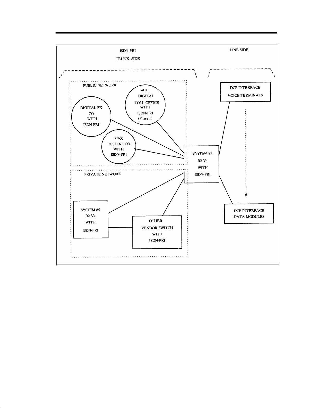
System 85 R2V4 supports ISDN-PRI but not ISDN-BRI. However, System 85 R2V4 uses the lineside digital communications protocol (DCP) to provide end-to-end digital connectivity. The DCP
channel structure consists of 2I + 1S channel format. Each I-channel provides a 64K-bps
information (voice/data) channel, while the S-channel provides an 8K-bps signaling channel. The
DCP is similar to ISDN-BRI, both in structure and in function. The DCP was AT&T’s early attempt
to offer (what at that time was) the evolving BRI standard. Figure 1-1, System 85 R2V4 ISDN
Configuration, shows various trunk-side and line-side connections to a System 85 R2V4.
Page 29
INTRODUCTION
1-5
Figure 1-1. System 85 R2V4 ISDN Configuration
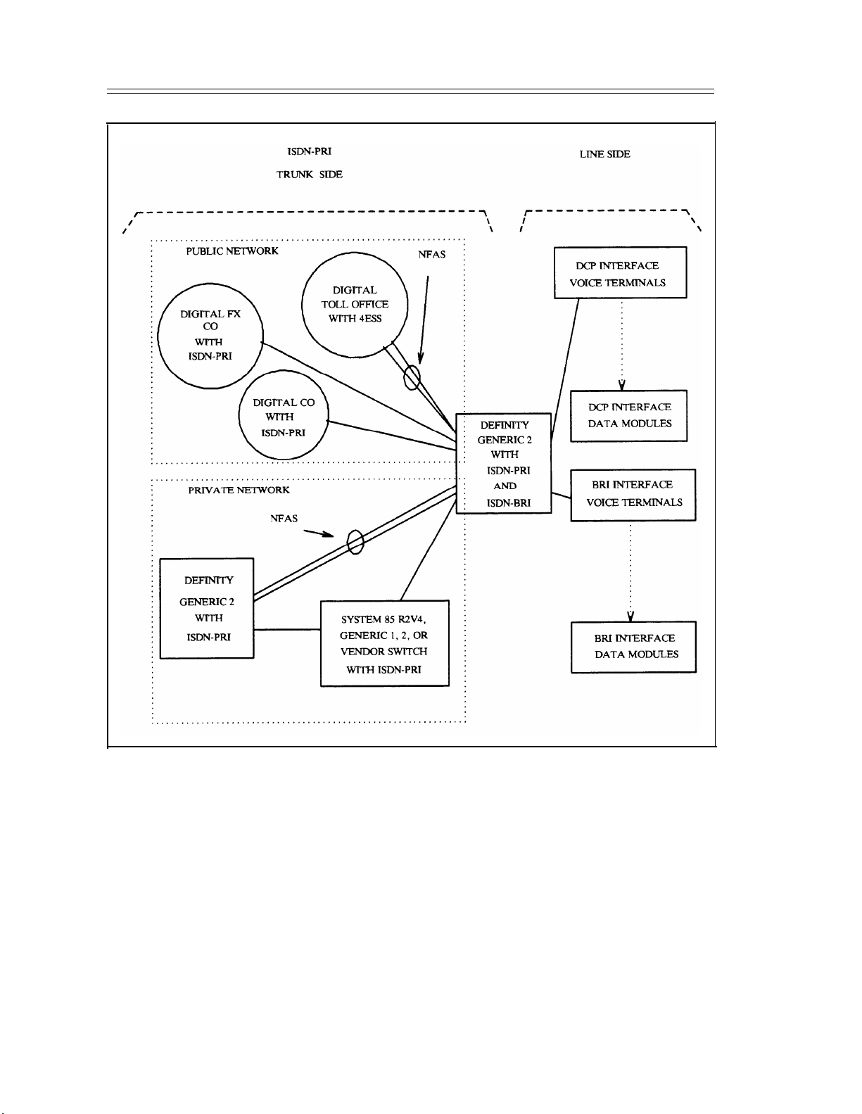
Generic 2 provides a signaling method called nonfacility-associated signaling (NFAS). NFAS allows
a D-channel on one PRI facility (sometimes called a PRI pipe) to provide signaling for B-channels on
another PRI pipe. With NFAS, if two or more PRI pipes are present, an optional D-channel backup
feature is available. One D-channel is administered as the primary D-channel on one DS1 and the
secondary D-channel on another DS1. Only one D-channel per primary-secondary pair can be active
at a time. If the primary D-channel fails, the signaling function is switched automatically to the
secondary (sometimes called the backup) D-channel. Without D-channel backup, D-channel failure
results in loss of service for all calls passing through a PRI pipe.
Generic 2 offers ISDN-BRI, however, some BRI capabilities are not initially available. Figure 1-2,
Generic 2 ISDN Network Configuration, shows a Generic 2 switch in a sample network.
Page 30
1-6
INTRODUCTION
Figure 1-2. Generic 2 ISDN Network Configuration
Generic 1 and Generic 2 provide ISDN-PRI but do not support wideband channels. Additionally,
ISDN-BRI is not currently supported in Generic 1. However, end-to-end digital connections are
permitted via line-side DCP-interface voice terminals and DCP-interface data modules. Figure 1-3,
Generic 1 ISDN Network Configuration, shows a Generic 1 in a sample network.
Page 31

INTRODUCTION
1-7
Figure 1-3. Generic 1 ISDN Network Configuration
Channels
Each channel transports 8-bit words (signal samples). Signal samples repeat at an 8K-Hz rate
yielding a 64K-bps signal. The channels may be used to transmit any of four different types of
signals.
Page 32

1-8
INTRODUCTION
Voice
Voice-grade
data
Analog voice date is encoded into 64K-bps pulse-code modulation (PCM)
samples using an encoding technique known as the Mu-255 law. Details of this
encoding technique are not given here. The important point is that each DS1
channel can transport PCM-encoded 64K-bps voice signals.
Voice grade data is also called PCM Data and voiceband analog data. Modems
receive digital data, convert the data to an analog voiceband signal, and transmit
it over analog phone lines. Whenever the modem connects to a digital switch,
the modem analog output signal undergoes the same PCM encoding process as
voice. Therefore, the modem output is termed voice-grade data.
This two-step process of first converting digital data to analog data and then to
64K-bps PCM data is necessary for transmitting data on DS1/DMI facilities that
are either administered for robbed-bit signaling (RBS) or routed over a
combination of digital and analog sections.
An attribute of voice-grade data is that signaling information can be inserted into
the least-significant bit (LSB) of the PCM words without destroying the data.
This capability cannot be done for those DS1 facilities that transmit digital data
(described below).
Voice-grade data calls placed over DS1/DMI facilities, which use RBS, require
the use of a modem to permit this two-step conversion. Actually, the modem
pool (modem-to-switch) interface does this conversion.
Digital data
NOTE: Voice-grade data is limited to speeds provided by the modem
(typically 19.2K-bps or less). However, DS1 channels accommodate data at
rates up through 56K-bps.
Digital data operates at 64K-bps and 56K-bps rates. Computers and data
terminals generate digital data. The computer ports and data terminals interface
to data modules. Data modules transmit the digital data (in digital form) to the
switch. When this digital data is switched into a DS1/DMI channel without any
intervening processes (such as modem pool conversion or embedded signaling
information), the channel is said to provide 64K-bps data capability (also known
as mode-1 data). The important point here is that when a DS1/DMI signal
consists of digital data, every bit that goes in at one end must come out the other
end unaltered; otherwise, the data would be destroyed.
Data modules support 56K-bps digital data over robbed-bit facilities.
NOTE: Although the digital data channels transmit synchronous 64K-bps
data, computer ports and data terminals do not typically generate digital data
at this rate. Data modules provide data rate adaptation (modes 0, 1, and 2)
and generate nulls or fill characters (as required) for maintaining the 64Kbps data rate.
Page 33

INTRODUCTION
1-9
To properly transmit digital data, the following conditions must be met:
●
The data communications protocol must meet the 1s-density requirement (see
Line-Coding Formats later in this chapter).
●
24th-channel signaling must be administered (except for mode 1 data which
can use robbed-bit facilities). (See 24th-Channel Signaling later in this
chapter.)
●
The transmission link must consist of an end-to-end digital facility.
Signaling information for the other 23 channels (24th-channel signaling).
B-Channels
For System 85 R2V4 and Generic 1, ISDN-PRI B-channels are identified as channels 1 through 23.
For Generic 2, ISDN-PRI B-channels may be identified as channels 1 through 23 when a DS1 facility
provides a D-signaling channel or channels 1 through 24 it does not. ISDN-PRI B-channels can only
be used for trunk applications. Each B-channel can be used to transmit 64K-bps digitized voice and
either restricted digital data or unrestricted digital data.
D-Channels
When a DS1 link contains a D-channel, it is said to use facility associated signaling (FAS). When a
DS1 link does not contain a D-channel, it is said to use nonfacility-associated signaling (NFAS).
With NFAS, the call-control signaling for the 24 B-channels is associated with a D-channel on
another DS1 link. Generic 1 and Generic 2 have NFAS. Earlier products provide FAS only.
ISDN-PRI facilities permit D-channel signaling only over the 24th channel. The full bandwidth
(64K-bps) of the D-channel supports the signaling requirements for the associated B-channels. A
fundamental difference between the D and B-channels is that each B channel provides a continuous
and independent communications link, while the D-channel is used exclusively by the switch to
provide call-control signaling and feature services for the associated B-channels.
D-Channel Backup (Generic 2)
Since some network charges are based on the number of D-channels, cost savings are realized by
using NFAS and having large groups of B channels. However, the reliability of a large group of Bchannels may be decreased because of the dependence on a single D-channel. The D-channel backup
capability improves reliability by providing two D-channels. These two channels are called the
primary D-channel (D1) and the secondary D-channel (D2). Only one D-channel is active at a time,
that is, when the primary D channel is active the secondary is idle (and vice versa). If the primary
channel fails, the secondary channel switches to the active state.
When NFAS is used with D-channel backup, the two D-channels should be located in different DS1
modules. Which DS1 links contain the primary and secondary channels is based on D-channel
loading and the customer’s perception of B-channel importance if the B-channel is lost.
Page 34

1-10
INTRODUCTION
Circuit-Switched Versus Packet-Switched Channels
A circuit-switched channel provides the full bandwidth of a channel to the single terminating
application on an end-to-end basis. For example, the full 64K-bps B-channel bandwidth is
continuously available for both calling and called users.
As a contrast, a single packet-switched channel divides the bandwidth of a channel into multiple
logical channels. The logical channels use a channel's bandwidth on an as-required and multiplexed
basis. The order in which the logical channels are multiplexed is controlled by a packet switching
protocol, such as X.25. A System 85 R2V4, Generic 2, and Generic 1 ISDN-PRI provide only
circuit switched B-channels. External hardware may be used for providing packet switched channels
and thus provide access to a variety of packet networks.
Framing Formats
A frame is a set of 24 8-bit time slots grouped as a single transmission unit. Each DS1 frame has 192
bits (24 x 8), plus 1 bit (called a framing bit) that is inserted at the beginning of each frame. Since
each frame repeats time slots in the same sequence as previous frames, time slots representing a single
conversation or data stream form a channel. DS1 frames repeat the 24-channel sequence in the same
order as previous frames at an 8,000 frames per second rate.
There are two methods or formats for providing framing. Either format may be chosen, depending
on the equipment and application. The type of framing used at both equipment ends of a DS1
transmission facility must be identical. The framing format does not place any requirement on the
type of signaling or line coding to be used.
D4 Framing
The D4 framing format uses a synchronization scheme that relies on a continuously-repeated 12-bit
fixed pattern. This 12-bit synchronization pattern is formed by the framing bit from 12 consecutive
frames. The receiving port finds the pattern across frames by identifying the beginning and end of
each frame. The 12-frame unit which contains the synchronization pattern (one D4 cycle) is called
the D4 superframe. Figure 1-4, D4 Framing, shows the D4 superframe format for a
DS1/DMI/ISDN-PRI signal.
Page 35

INTRODUCTION
1-11
Figure 1-4. D4 Framing
The D4 framing is the format compatible with D4-channel banks. The D4 framing is the only
framing format supported by all equipment used with System 75 and System 85 DS1 (such as CEMs
and CDMs).
The DS1, while providing an error-detection capability, monitors the receive sequence of framing bits
to detect transmission errors. If a transmission error (such as a noise hit) causes a bit in the framing
pattern to be in error, a misframe is said to have occurred. The DS1 counts misframes and uses the
count for processing the facility performance indicators, such as bit error rates, major alarms, and
minor alarms.
Page 36

1-12
INTRODUCTION
ESF Framing
Initially, this format was called F , pronounced “F sub e,” for framing extended. It is now called
e
extended superframe (ESF). The ESF framing format was developed after the D4 format. Not all
equipment used with a DS1/DMI-BOS interface supports ESF. Specifically, most D4-channel banks
(unless they are configured as LIU-3ESF or equivalent) and CDMs do not currently support ESF
framing. (See figure 1-5, DS1 Extended Superframe Format.)
FRAME
NUMBER
1
2
3
4
5
6
7
8
9
10
11
12
13
14
15
16
17
18
19
20
21
22
23
24
FRAME BIT
DEFINITIONS
DATA LINK F BIT (DL)
CRC-6 F BIT
DATA LINK SIGNAL
FRAME SYNC PATTERN
DATA LINK SIGNAL
CRC-6 F BIT
DATA LINK SIGNAL
FRAME SYNC PATTERN
DATA LINK SIGNAL
CRC-6 F BIT
DATA LINK SIGNAL
FRAME SYNC PATTERN
DATA LINK SIGNAL
CRC-6 F BIT
DATA LINK SIGNAL
FRAME SYNC PATTERN
DATA LINK SIGNAL
CRC-6 F BIT
DATA LINK SIGNAL
FRAME SYNC PATTERN
DATA LINK SIGNAL
CRC-6 F BIT
DATA LINK SIGNAL
FRAME SYNC PATTERN
FRAME BIT
CHANNEL 1
8-BITS
8-BITS
8-BITS
0
0
1B
0
1
1D
8-BITS
8-BITS
7-BITS
8-BITS
8-BITS
8-BITS
8-BITS
8-BITS
7-BITS
8-BITS
8-BITS
8-BITS
8-BITS
8-BITS
7-BITS
8-BITS
8-BITS
8-BITS
8-BITS
8-BITS
7-BITS
CHANNEL 2
A ROBBED BIT (OPTIONAL)
ROBBED BIT (OPTIONAL)
ROBBED BIT (OPTIONAL)
C
ROBBED BIT (OPTIONAL)
Figure 1-5. DS1 Extended Superframe Format
The ESF format consists of a 24-bit framing pattern. Compared to the 12-bit fixed pattern for D4,
only 6 of the 24 bits carry a fixed pattern. The other 18-bits consist of a 6-bit error detection code,
called the cyclic redundancy check (CRC) sum, and a 12-bit facility data link signal. At the transmit
Page 37

INTRODUCTION
1-13
end, one framing bit is inserted in each succeeding 193rd bit-position of the DS1 signal. The receive
end uses the framing pattern to synchronize the end of one 24-channel block and the beginning of the
next, to identify the channels that contain embedded signaling information, and to detect errors.
NOTE: This 4K-bps facility data link is designed to maintain and supervise a DS1 facility.
However, this link is used by a System 75 and System 85 DS1s only for transmitting yellow
alarms.
Each 24-frame entity, spanning one ESF cycle, is called the ESF superframe. Figure 1-6, DS1 Signal,
Framing Format, and ESF Superframe (24 Frames), shows an ESF superframe.
NOTE:
For RBS, frames 6, 12, 18, and 24 carry signaling information.
Figure 1-6. DS1 Signal, Framing Format, and ESF Superframe (24 Frames)
Page 38

1-14
INTRODUCTION
The CRC is used at the receive end to detect transmission errors. The CRC is calculated at the
transmit end and multiplexed into the DS1 signal. At the receive end, the CRC is recalculated using
the data in the received ESF superframe and then compared with the received CRC. If a
transmission error (such as one caused by a noise hit) results in the CRC being in error, a misframe
occurs. The DS1 interface counts misframes and uses the count for processing DS1 facility
performance indicators, such as bit error rates, major alarms, and minor alarms.
The ESF reframing algorithm can determine the correct framing pattern embedded in the
DS1/DMI/ISDN-PRI signal even if the 8-bit words for the 24 channels carry a bit sequence identical
to the framing pattern. Because of this and its superior error detection capabilities, the ESF format
should be used (rather than D4 framing) whenever an application permits.
Signaling Types
DS1/DMI provides four distinct and different types of signaling. One type is called robbed-bit
signaling (RBS). The other three types are variations of 24th-channel signaling called AT&T
proprietary signaling, DMI bit-oriented signaling (DMI-BOS), and DMI message-oriented signaling
(DMI-MOS). The type of signaling used does not place any requirements on the type of framing or
line coding. However, a direct relationship exists between the type of signaling used and the type of
signals transmitted over the channels. A facility that uses RBS transmits voice or voice-grade data; a
facility that uses 24th-channel signaling transmits voice or digital data.
Robbed-Bit Signaling
Robbed-bit signaling (RBS) replaces (that is, robs) the least significant bit (LSB) of each channel’s
8-bit word in every 6th frame. It then replaces this word with the signaling information for that
channel. For D4, the 6th and 12th frames carry RBS; for ESF, the 6th, 12th, 18th, and 24th frames
carry RBS (refer to figures 1-4 and 1-5, respectively).
Because the signaling information is carried embedded in each channel’s 8-bit word, RBS signaling is
also called inband signaling.
Facilities using RBS cannot be used to transmit 64K-bps data.
24th-Channel Signaling
24th-channel signaling permits DS1 channels to use the full 64K-bps bandwidth on the other 23
channels. This type of signaling provides clear channels (clear, except for 1s-density issues). Ones-
density issues are those issues associated with the facility being used. (See Line-Coding Formats for
more information.) 24th (D-channel) signaling places the signaling bits (or LAPD message bytes) for
channels 1 through 23 into the 8-bit word of the 24th-channel.
The AT&T proprietary signaling type was the first type of 24th-channel signaling provided by System
75 and System 85 DS1/DMI. It was developed to carry DCP-formatted data (in digital form)
between System 75 and/or System 85 switches. AT&T proprietary signaling is described in the initial
release of the DMI technical specification.
Page 39

INTRODUCTION
1-15
For AT&T proprietary signaling, a complete set of signaling information is sent every 24 frames.
This 24-frame period is not synchronized to the 12-frame superframe format of D4 framing or to the
24-frame superframe format of ESF framing. Each signaling word contains the equivalent of a
channel identification number and the signaling state for that channel. The channel identification is
necessary since the channel signaling information is not directly related to a particular frame number
and does vary as with multilinked facilities.
For DMI-MOS (and ISDN-PRI), each word on the 24th-channel carries a multiword LAPD message
within the signaling channel. Messages are transmitted only when signaling is required for one of the
other 23 channels along with header and trailer data that identifies the channel for which the signaling
is sent. Individual words have no meaning.
The channel identification, its associated signaling, and their relationship to a frame number are
related to the concept of superframe synchronization (see the Superframe Synchronization section later
in this chapter).
Table 1-1, 24th-Channel Signaling Arrangement, depicts one sample frame number and signaling
channel relationship (many other relationship rotations are possible).
TABLE 1-1. 24th-Channel Signaling Arrangement
D4
Signaling Superframe
Frame No. Frame No.
1 11 7
2 12
3
1 9
4 2
5 3
6 4
7
8
5
6
9 7
10
11
8
9
12 10
ESF
Superframe
Signaling
D4
Superframe
Frame No. Frame No. Frame No. Frame No.
13 11 19
8
14
12
15 1 21
10
11
12
13
14
15
16
17
18
16
17
2
3
18 4 24
19
20
21
22
23
24
5
6
7 3
8
9 5
10
ESF
Superframe
20
22
23
1
2
4
6
Some types of public network equipment were incompatible with 24th-channel signaling and, as a
result, another type of 24th-channel signaling called DMI-BOS, was developed. For DMI-BOS,
specific 24th-channel bit locations carry framing and alarm data, and signaling information for the
other 23 channels. Unfortunately, DMI-BOS and AT&T proprietary signaling are not compatible.
DMI-BOS must be used only for connections to host computers and other vendor’s equipment that
meets the DMI technical specification for BOS.
For System 85, the ANN11B and ANN11C support only AT&T proprietary signaling. The
ANN11D and ANN11E supports both AT&T proprietary signaling and DMI-BOS. The ANN11D
and ANN11E defaults to DMI-BOS, but automatically switches to AT&T proprietary signaling
whenever the distant end supports only AT&T proprietary signaling.
Page 40

1-16
INTRODUCTION
For System 75, the TN722 provides only AT&T proprietary signaling. However, the TN722B can be
administered to provide either AT&T proprietary signaling or DMI-BOS.
The CCITT Q.921 ISDN-PRI recommendations require that MOS-type signaling be used. In DMIMOS, signaling is done with messages that consist of a series of information elements (IEs). The
type of IEs used for a particular signaling message are generally determined by the conditions. (See
the Summary heading later in this chapter for a description of the different types of IEs.)
For System 85 R2V4 and Generic 1, each ISDN-PRI facility uses the 24th channel as the D
(signaling) channel. A Generic 2 switch introduced FAS (administered as 23B + 1D), and NFAS
(administered as 24B).
Line-Coding Formats
Line coding is the pattern data assumes as it is propagated over a communications channel.
Governing line coding is a set parameters that must be defined for all digital transmissions. These
transmission parameters specify the voltage level and patterns in which 1s and 0s can appear on the
line.
The parameters chosen for a given transmission stream must meet the requirements set by the
hardware through which the data is transmitted. Most notable among these requirements are two
established by the AT&T network. The first of these requirements dictates the voltage levels at
which ones and zeros are transmitted. Alternating mark inversion line coding was adopted to fulfill
this requirement. The second requirement, known as the ones density requirement states that in every
stream of 15 consecutive digits, a one must appear. Zero code suppression (ZCS) and 8-bit zero
substitution (B8ZS) were adopted to meet this requirement. Both ZCS and B8ZS ensure that a one
appears in each consecutive octet in every transmission stream. These line coding formats are
described next in more detail.
Alternate Mark Inversion
All transmissions generated by DS1s are encoded in the alternating mark inversion (AMI) line coding
format. With AMI, a DS1 signal is a continuous stream of “1s” (encoded as +3V and –3V pulses)
and “0s” (encoded as 0V pulses). For every 1 in the bit stream, a pulse occurs; for every 0, no pulse
occurs. The pulses of successive 1s are of opposite polarity regardless of the number of intervening 0s
(lack of pulses). That is, a the polarity of a 1’s pulse alternates plus or minus between successive
ones. This type of line coding is called bipolar or alternate mark inversion (AMI). (See figure 1-7,
Alternate Mark Inversion.)
Page 41

v(t)
+3
-3
010110111
Figure 1-7. Alternate Mark Inversion
INTRODUCTION
1-17
t
1s-Density Requirement
On the receive side, a DS1 uses the received bipolar pulses of the DS1 signal to recover the 1.544Mbps clock signal that transmitted the bit stream. To do this, the bipolar signal must contain enough
pulses (1s) to allow the clock recover circuit to remain synchronized with the bipolar signal. This is
known as the 1s-density requirement.
If there are not enough 1s, the clock frequency drifts causing the bits to be received at a different rate
than they were transmitted. If this continues, a surplus or deficiency of bits will accumulate at the
receiving end. Eventually this surplus or deficiency will equal an entire frame’s worth of bits (192).
Then, an entire DS1 frame is either repeated or deleted to compensate for the differences in
transmitting and receiving clock frequencies. This is called a slip. (Slips can also be caused by
incorrect switch synchronization as discussed in the Synchronization of Digital Facilities chapter.)
The 1s-density requirement specifies that a minimum 1s-density average of 12.5% be maintained and
that a maximum of 15 consecutive 0s can occur in the bit stream. If this requirement is not met, it is
assumed that an error has occurred and that the network equipment will insert a series of ones into
the bit stream to compensate.
Zero Code Suppression and Bipolar with 8 Zero Substitution
To guarantee that data transmitted over a DS1 facility contains enough 1s, a DS1 uses one of two
coding options used with AMI line coding. The first option is zero code suppression (ZCS) and the
second is bipolar with 8 zero substitution (B8ZS). The option chosen is made through DS1
administration, with ZCS being the default. When ZCS is used, DS1 provides restricted channels.
When B8ZS is used, DS1 provides unrestricted or clear channels.
Page 42

1-18
INTRODUCTION
Restricted Channel
A restricted channel is a digital transmission facility restricted to transmissions in which an all-0s
octet (eight 0s in a single time slot) is never transmitted. In restricted channels, the line equipment’s
transmitters use ZCS line coding. This format monitors the 24 DS0 channels and prevents eight
consecutive 0s (the all-0s octet) from being transmitted. On detecting eight 0s, the line-coding
format forcibly changes the second LSB to a 1 when it is transmitted because too many 0s causes loss
of synchronization. This ensures that the 1s-density requirement is met but the receivers in these
facilities have no way of knowing which 1s were 0s when transmitted and the data is destroyed.
Therefore, user data transmitted in the DS0 channels with ZCS must be restricted to not generate the
all-0s octet (hence the name restricted channels).
ZCS line coding is done in one of two ways:
●
For data, a data communications protocol that does not produce the 0s octet is used. The highlevel data link control (HDLC) protocol, or those protocols built on HDLC (such as the DCP,
PRI, and BRI signaling protocols and DMI modes 2 and 3), do not generate an all-0s octet (when
the signal is inverted before transmission) and therefore meets these requirements. Data mode 0
does not generate an all-0s octet if the data terminal equipment (DTE) transmits the HDLC
protocol to the data module. (Data mode 0 is used only when a customer provides HDLC.)
For ISDN applications the LAPD protocol is used to make D-channel signaling messages. LAPD
is an HDLC-based protocol. The D-channel is inverted before it is transmitted and, therefore,
ZCS is never activated.
●
For voice, 64K-bps PCM encoding is sent from the voice terminal over one of the I channels
(DCP) or B-channels (ISDN-BRI) for call processing. At the DS1 board, when an all-0s octet is
encountered on an outgoing call stream, the second least-significant bit of the octet is forcibly
changed to a 1 before transmission. When the outgoing call is transmitted from a DS1 board, the
board cannot discriminate between originating channel types. Since PCM does not generate an
all-0s octet, the ZCS line-coding format does not affect 64K-bps PCM voice.
Unrestricted or Clear Channel
An unrestricted channel is a transmission facility that has no restrictions on the number of
consecutive 0s so arbitrary insertions of 1s will not occur (as with ZCS line coding). The line
equipment’s transmitters and receivers in these facilities use bipolar with 8 zero substitution (B8ZS)
line coding. This format monitors the DS1 bit stream, detects strings of eight consecutive 0s (not
restricted to an individual octet), and encodes these 0s (including framing bits) into a unique bipolar
pulse sequence (called a bipolar violation) that meets the 1s-density requirement. This sequence is
detected at the receiver and converted back to eight consecutive 0s. Therefore, digital data can be
transmitted on these channels without concern about its content (hence, the name unrestricted or
clear channel) as shown in figure 1-8, Example of B8ZS Line Coding. See AT&T Compatibility
Bulletin No. 144: Clear Channel Capability for the exact algorithms used in B8ZS.
Page 43

INTRODUCTION
1-19
UNCODED
BIT STREAM
PULSE
STREAM
010011
0+00-+
00000000
000+0-+
VIOLATIONS BASED ON POLARITY
OF LAST 1 TRANSMITTED
111
-+-
00000000 00000000
000-+0+-
000-+0+-
01
0+
Figure 1-8. Example of B8ZS Line Coding
Applications requiring B8ZS line coding are currently in the minority, but it is expected that in the
long term they will be in the majority. The B8ZS provides no substantial advantages for voice and
voice-grade data signals over ZCS. However, if the data communications protocol does not already
maintain proper 1s-density, then B8ZS is essential for transmitting unrestricted digital data. Even if
the AT&T network contains unrestricted facilities, the access facilities through the local exchange
may not, which means that you would still be required to use the ZCS option.
Differences Between ZCS and B8ZS
Differences between ZCS and B8ZS include:
1.
ZCS requires that user data be presented via a data communications protocol that does not
generate the all-0s octet, while B8ZS has no such restrictions
2.
ZCS monitors each B-channel (not including the framing bits), while B8ZS monitors the entire
DS1 facility (including framing bits)
ZCS maintains 1s-density at the expense of altering the data, while B8ZS maintains 1s-density
3.
without altering the data
4.
When detecting the all-0s octet with ZCS, the transmit side inserts a 1 in the second LSB,
which will not be corrected from by the receiving side. When detecting eight consecutive 0
with B8ZS, switch in the special B8ZS code word. The receive end monitors the DS1 bit
stream and will switch in eight 0s when detecting B8ZS code words.
S
Page 44

1-20 INTRODUCTION
Bipolar Violations
As noted earlier, the DS1 bit stream is transmitted as a series of pulses. Successive pulses, regardless
of the number of intervening spaces (0s), are of opposite polarity. A bipolar violation is the
occurrence of two consecutive identical pulses, that is, when two positive or two negative pulses are
received in a row, regardless of the number of intervening 0s.
Usually, bipolar violations are caused by noise hits on the DS1 bit stream. For B8ZS, strings of eight
0s are encoded into special sequences that include bipolar violations. Some network-interface
equipment, primarily most network channel-terminating equipment, or NCTE (also called customer-
service units or CSUs), and network transmission equipment (network high-speed multiplexer), will
remove bipolar violations. Therefore, if an application requires B8ZS line coding, then the end-toend transmission facilities must support B8ZS. Otherwise, the B8ZS encoding will be destroyed.
Additional NCTE information is provided in chapter 3, DS1 Transmission and Cabling, and chapter
7, Administration Issues, Options, and Requirements.
A Generic 2 DS1 interface does not process bipolar violations, because they are removed by most
NCTEs.
Communication Protocols and 1s-Density Requirement
As mentioned earlier, there are other methods (communication protocols) used to prevent strings of
0s from occurring in the DS1 bit stream. One such protocol is used with System 75 and System 85 as
described next.
System 75 and System 85 digital ports interface to data modules. These data modules encode user
data consistent with the DMI specification. The DCP is specifically designed to prevent generation of
the all-0s octet when using DMI modes 1-3 and, therefore, either the ZCS or B8ZS line-coding
formats may be used. But since the ZCS format has no special equipment requirements, ZCS is the
preferred format.
Table 1-2, Data-Module Capabilities, summarizes the capabilities of the data modules that can be
used on Generic 2 for communications over an ISDN-PRI link. For further details on each data
module, refer to About This Document for a list of related data module documents. For complete
definitions of the four DMI modes (0 through 3), refer to Digital Multiplexed Interface (DMI)
Technical Specification, Issue 3.2, November 1989 (555-025-204). Ask for the most recent version.
Page 45

TABLE 1-2. Data-Module Capabilities
INTRODUCTION
1-21
Data
Module
DTDM
MPDM
MPDM/M1*
3270 A
3270 T
PC/PBX
w/ASCII
Term Emul
PC/PBX
w/3270
Emulation
7500
UDM-T
DMI
Mode
2
0
1
2
1
2
2
3
3
2
3
3
0
1
2
3
User Data
Rate
300 - 19.2K
64K
56K
to 19.2K
56K
to 19.2K
to 19.2K
64K
64K
to 19.2K
64K
64K
64K
56K
to 19.2K
64K
Sync/
Async
both
sync
sync
both
sync
both
both
sync
sync
both
sync
sync
sync
sync
both
sync
Bit
Invert
yes
yes
no
yes
no
yes
yes
yes
yes
yes
yes
yes
no
no
yes
yes
Protocol
Packaging
HDLC
no
DDS
HDLC
DDS
HDLC
HDLC
LAPD
LAPD
HDLC
LAPD
LAPD
no
DDS
HDLC
LAPD/X.25
Handshake
mode 2
mode 2
mode 2
yes
no
no
mode 3/2 adapt
mode 3/2 adapt
mode 3
mode 3/2 adapt
mode 3/2 adapt
mode 3
no
no
mode 2
mode 3/2 adapt
Notes
1, 9
2, 9
3
4
5
6
3
7, 8
MPDM — modular processor data module
NOTES:
1.
A mode-2 handshake works only on 64K-bps facilities (such as robbed-bit). (Use an MPDM/M1* for mode-1 calls made over robbed-bit
facilities.) Since an ISDN-PRI link between a System 85 R2V4 and a Generic 1 uses these facilities, this handshaking will work.
2.
You must use the MPDM/M1* when the far end data circuit-terminating equipment (DCE) is not another AT&T data module (does not do
a mode-2 handshake).
“Mode 3/2 adaptive” means that a mode-3 handshake is attempted first. An algorithm is then followed to determine the far-end's mode and
3.
either switch to mode 2 or continue in mode 3.
4.
Mode-3 data can only be circuit switched in System 85 R2V4 and Generic 1.
Mode 2 on the PC/PBX Connection is supported under the ASCII terminal emulation package.
5.
It is expected that an option switch will be added to the 7500 to invert or not invert.
6.
On outgoing mode-3 calls, the 7500 does not invert bits. On incoming calls, the 7500 checks the low-layer compatibility IE and either
7.
inverts or does not invert depending on the contents of the IE.
The algorithm for the mode 3/mode 2 handshake is different for DCP data modules and BRI data modules, which could cause DCP/BRl
8.
interworking problems.
Bit inversion is administrable; “no” is the default value.
9.
Some applications where DCP and DMI formatted data are not used include the following:
a. When 64K-bps data is transmitted across DS1/DMI/ISDN-PRI facilities (via a dedicated switch
connection or DSC) to an endpoint such as a channel bank channel unit.
b. When a point-to-point data application is done with CDMs to drop and insert DS0 channels.
Here, it is up to the user endpoints to ensure that the 1s-density requirement is met.
Page 46

1-22
INTRODUCTION
The method used to provide ACCUNET® switched digital service (used by D4-channel banks) also
maintains the 1s-density requirement. This method uses only seven of the eight bits for each DS0
channel's 8-bit word to carry user data. The remaining bit (8) is “wired” to a 1. (MPDM/M1* is
compatible with ACCUNET switched digital service).
IMPORTANT CONCEPTS
Important concepts discussed in this section include:
●
Common-channel signaling
●
Alternate voice/data (AVD) trunks
●
Bearer capability (BC)
●
ISDN call processing
●
CBC Service Selection
●
Networking restrictions and ISDN-PRI limitations
Common-Channel Signaling
Originally, common-channel signaling (CCS) meant that any of the 24 channels could be used to
transmit signaling for the other 23. To offer CCS, both RBS and 24th-channel signaling would have
to be disabled to make all 24 channels available to transmit signaling.
Current AT&T applications use only the 24th-channel as the signaling channel and, therefore, the
term CCS has been used more and more as a synonym for 24th-channel signaling. Misuse of the
term CCS and its original definition have contributed to some misunderstanding. When comparing
System 75 and System 85 DS1/DMI administration procedures, you will find that:
The current definition of CCS is used when administering System 75 and Generic 1, although it
a.
is 24th-channel signaling that is actually being administered.
b. The original definition of CCS cannot be administered for System 85 or Generic 2, however,
24th-channel signaling can be administered. For Generic 2, the equivalent terms, 23B + D or
24th-channel signaling, are used rather than CCS.
Alternate Voice/Data (AVD) Trunks
AVD is an attribute of trunks used with System 85 R2V4 and earlier releases, and System 75 R1V3
and earlier releases, and all Generic 1 switches. For Generic 2, bearer capability, which identifies
the capabilities previously identified with AVD plus many more, is used instead.
AVD relates a trunk group’s translations to the type of signaling required to support the trunk group.
From the software perspective (and when applicable), a trunk group is administered for either AVD
or voice. Trunk groups administered for AVD may be used for both voice and digital data
applications and require a DS1 that is administered for 24th-channel signaling.
Page 47

INTRODUCTION
1-23
Bearer Capability (BC)
System 85 R2V4 introduced the administration attribute known as bearer capability (BC). The
primary function of BC is to specify the transport mode and the channel requirements
(clear/restricted) needed for completing a data call. BC is used for determining compatibility when
non-ISDN facilities are connected to ISDN facilities, including originated calls, terminated calls, and
tandem connections. BC must be administered for all trunk groups, every extension’s class- of-service
(COS), and all Automatic Route Selection (ARS) routing-pattern preferences.
System 85 R2V4
For System 85 R2V4, there are the five different BC codes:
0
Voice and voice-grade data — should be administered for DCP voice extensions, analog lines,
analog trunks, and data applications that use modems.
NOTE: Except for 56K-bps, the trunk attribute AVD indicates 24th-channel signaling and
whether a modem pool must be inserted to complete the call.
1
Mode-1 data — with the 56K-bps option — should be administered for 56K-bps synchronous data
applications. DCP uses mode-2 handshake unless using MPDM/M1*.
NOTE: The appropriate data module must be installed and optioned for 56K-bps operation.
This arrangement can be used to support the special format required to support ACCUNET
switched digital service or 56K-bps basic service (if using MPD/M1*).
2
Mode-2 data — for data modules and EIA data terminations that do not operate as packet-mode
data and are optioned for the following data rates: low, 300, 1200, 2400, 4800, 9600, 19.2K-bps.
When appropriate, trunk groups that route to DS1/DMI/ISDN-PRI facilities should be
administered for mode 2 data. DCP inverts the data and uses mode-2 handshaking.
3
Mode-3 data — should be administered for trunk groups that are used for packet mode data.
DCP inverts the data and uses mode-3/2 handshaking. This is used for patterns associated with
ISDN-BRI or PC-PBX.
4
Mode-0 data — should be administered for digital endpoints that are used to transmit 64K-bps
data. These may only be DCP extension, DMI-BOS trunks, and ISDN-PRI facilities. DCP
inverts the data and uses Mode 2 handshaking.
Depending on the administered value, an originated call will either require an ISDN channel, have an
administered preference that an ISDN channel be used, or have no requirement for what type of
facility is used to complete the call. For terminated calls and tandem connections, the BC class
(BCC) for both links must be compatible. For example, voice and voice-grade data are equivalent to
the no requirement case since the call characteristics for all other types of facilities are satisfactory.
In contrast, B-channels transmitting 64K-bps digital data require that the connected channel have the
same call characteristics (the same BCC) such as where an ISDN channel is required. This
information appears in the traveling class mark (TCM) IE (layer 3) codeset 7 in System 85 R2V4,
and in codeset 6 in Generic 2.
Page 48

1-24
INTRODUCTION
Generic 1
For information about how BC is done for Generic 1, refer to the AT&T DEFINITY 75/85
Communications System Generic 1 and System 75 and System 75 XE Feature Description (555-200-
201).
Generic 2
Generic 2 continues the bearer capability concept with bearer capability class of service, (BCCOS).
With BCCOS, switch administration software provides a range of codes from 0 through 255. Codes 0
through 8 are predefined as:
Voice only — used for voice application extensions (such as DCP and ISDN-BRI extensions,
0
analog lines, and analog trunks)
Mode 2 data — used for EIA data terminations, and DCP or BRI data modules that do not
1
operate as packet mode data and are optioned for any of the following data rates: low, 300, 1200,
2400, 4800, 9600, or 19.2K-bps
Mode 3/2 adaptive data — used for data applications that can run both mode 3 and mode 2 (such
2
as BRI, PC/PBX, and the 3270 data module). The connection is first established with mode 3; if
mode 3 fails, mode 2 is used.
Unknown digital — used for those calls of any mode (0-3) where the signaling message does not
3
specify a mode (such as DS1 trunks using common-channel or 24th-channel signaling)
4
Unknown analog — used for voice or voice-grade data calls where the signaling message does not
specify a type (such as analog trunks and robbed-bit DS1 trunks)
Voice-grade data — used for data applications that use modems
5
Mode-0 data — used for facilities that transmit 64K-bps data (DCP and BRI extensions, DMI-
6
BOS trunks, and ISDN-PRI facilities).
Mode 1 data — used for 56K-bps synchronous data applications. The appropriate data module
7
must be installed and optioned for 56K-bps operation.
NOTE: This arrangement can be used to support the special format required for ACCUNET
switched digital service or 56K-bps basic service. DCP uses a mode-2 handshake unless an
MPDM/M1* data module is used.
Mode 3 data — should be administered for those applications requiring packet mode data.
8
Lines, trunks, and AAR/ARS preferences are assigned the default BC when one is not administered.
Generic 2 BCCOS defaults are intended to make a Generic 2 switch operate like a System 85 R2V4
(that is, Generic 2 will insert modem pool members and block calls). Table 1-3, Bearer Capability
Class of Service, lists the default values for common switch parameters.
Page 49

TABLE 1-3. BCCOS
INTRODUCTION
1-25
Switch Parameter
Analog Lines
All trunks except Host Access
Default Value
0
0
AAR/ARS Preferences 0
Host Access trunks
DCP data modules (both lines and trunks)
1
1
BRI extensions 0
NOTE: Extensions with multiple appearances must have the
same BC administered for each appearance.
ISDN Call Processing
ISDN-PRI is a trunk signaling type. ISDN trunk signaling is applied on a per-trunk-group basis and
is compatible with most existing switch features. ISDN trunk signaling also supports many new
networking features as described next.
Outgoing Calls
For outgoing calls, ISDN trunk groups may be categorized as those that:
Require that address digits be collected before trunk seizure (this can be done on non-ISDN
1.
trunks)
2.
Seize the trunk and do not outpulse any digits (this is called digit sending)
3.
Seize the trunk, obtain a start dial signal, and then begin digit outpulsing (this is called cut-
through dialing) to the terminating switch
The ISDN protocol requires that all dialed digits be collected before trunk seizure so cut-through
dialing cannot be provided for ISDN calls. Since few applications use digit sending, AAR or ARS
software must be used to collect and process dialed digits. If the switch is properly administered and
the numbering-plan data blocks are correct, AAR or ARS software processes dialed digits based on
data within the routing pattern and routing preference combinations resulting in the selection of a
particular service or feature. The routing pattern and routing preference combinations determine
which outgoing trunk group is selected and whether ISDN-PRI trunk signaling is used.
Each call routed to an ISDN signaling trunk group generates a series of Q.931 messages over the Dchannel. For example, the calling party IE of the ISDN-PRI setup message assembles the dialed
digits as ASCII numbers that correspond to the defined numbering-plan format. Also included
within the setup message are the BC requirements, B-channel identification, and network-specific
facilities (NSF). If the requested facilities are not available, either channel negotiation is begun or, if
appropriate, a cause failure code is returned and the call attempt is dropped. Otherwise, the called
switch responds with a call proceeding or alerting message.
Page 50

1-26
INTRODUCTION
Incoming Calls
Incoming ISDN calls are generally processed similar to outgoing ISDN calls. Initially, the called
switch receives a setup message over the D-channel and processes the contents of the setup message.
The call states of the switch, how the particular trunk groups are administered, and decisions taken as
a result of processing the setup message will determine exactly how the ISDN call is processed.
Summary
ISDN calls are processed using conventional, well-established, time-proven call-processing techniques.
The ISDN layer-3 software maintains status records for the ISDN call states, maintains the callreference value (CRV) for each B-channel, and starts sending messages. To request services from the
conventional call-processing routines, ISDN layer-3 software informs the switch of items such as
incoming calls and dialed digits.
The ISDN-PRI level-3 messages are a collection of IEs that are defined in the Q.931
recommendations. Each message has at least one IE. IEs are transmitted and received over the Dchannel. IEs contain three headers: protocol discriminator, call reference, and message type. Figure
1-9, ISDN Message Signaling Format, shows the message-signaling format.
FIRST OCTET
PROTOCOL DISCRIMINATOR
CALL REFERENCE
MESSAGE TYPE
INFORMATION ELEMENT
(OPTIONAL)
INFORMATION ELEMENT
▼
LAST OCTET
Figure 1-9. ISDN Message Signaling Format
IEs may be one or more octets long, depending on the element type. There are 133 different IE
identifiers (called codepoints) grouped into eight functional categories (codesets 0 through 7).
How trunk groups are constructed and how ISDN-supported features are administered determines
which B-channels may be selected to originate and terminate a particular call. Generally, any Bchannel may be used with both originating and terminating calls so a particular channel may support
a variety of applications and trunk types. In Generic 2, this capability is called ISDN dynamic where
channels can support several trunk types on a dynamic, call-by-call basis; in Generic 1, it is called
call-by-call (CBC). For both Generic 1 and Generic 2, this feature is called CBC Service Selection.
Page 51

INTRODUCTION
1-27
Administration software also allows services to be dedicated to specific channels by assigning a
channel to a particular trunk type. In this way, the switch always provides enough trunks for a
particular type of service. Channels administered for specific services are not available for ISDN-
dynamic uses.
With CBC Service Selection, calls requesting various types of services are routed, on a call-by-call
basis, over the same ISDN channels. To distinguish between various types of calls, the service type is
specified as a part of the message. Also included are BCC and NSF IEs.
The NSF IE identifies the feature or service provided by the network carrier (such as MEGACOM
service from AT&T). The called-party IE is used to specify routing digits such as the North
American dialing plan and the RNX.
The originating and terminating switches do channel negotiation to select a channel that is compatible
with both endpoints. Channel negotiation gives some control to the B-channel that is used for the
call. If the originating endpoint chooses a B-channel that is unacceptable to the terminating endpoint
(for example, planned use of the channel by the terminating endpoint), then the terminating endpoint
can request a change in the channel to be used for that call.
Although Q.931 recommendations allow for an asymmetrical design (that is, a user-to-network
protocol), most ISDN-PRI procedures on System 85 R2V4, Generic 1, and Generic 2 can be used
symmetrically. These communications systems can be administered as either the user side or as the
network side. When accessing a 4ESS switch, 5ESS
®
switch, or vendor-compatible toll-office or CO,
the customer-premises switch must have a user-side interface. For ISDN-PRI links between two
private network switches, one link must be administered for the user side and the other for the
network side.
Differences between the user side and network side are primarily related to resolving occurrences of
glare. Glare is a condition where both switches try to originate a call on the same channel
simultaneously. The network side always gains control of the channel and the user side backs down
(terminals are excused from certain protocol functions).
Calls from non-ISDN facilities (analog trunks and/or DMI-BOS trunks) may be connected to ISDN
facilities to provide end-to-end tandemed connections. The switch provides the required signal.
conversions through interworking routines. Depending on an extension's COS assignment and other
administration options, all conventional switch features and services may be used.
Depending on other administration options, message-associated user-to-user information (MAUUI)
or user-to-user information (UUI) may be transmitted from one user endpoint to the other. UUI
transfer includes the display of such things as calling number and calling party name.
Equipment manufacturers interpret the ISDN-PRI protocol in different ways. As a result, equipment
(and various equipment releases) use different approaches. Currently, one significant difference
affects codesets 6 and 7. System 85 R2V4 transfers UUI via codeset 7. System 85 R2V4 transfers
network specific information in codeset 7 according to the initial definition of ISDN. Generic 2
transfers network-specific information in codeset 6 leaving codeset 7 available for user-specific
information.
NOTE: Codesets 1 through 5 are reserved for future standards expansion.
Page 52

1-28
INTRODUCTION
CBC Service Selection
CBC trunk groups eliminate the need for dedicating specific B-channels to a particular service. CBC
Service Selection can dynamically select individual B-channels (from a group of B-channels) and
allocate those B-channels to any of the subscribed services. The selected B-channel may function as a
specific trunk type (for a specific service) during one call, then later the same B-channel may function
as a different trunk type (for a different service) during another call. The primary advantages of
CBC Service Selection include:
More efficient and effective use of ISDN-PRI network access trunks
●
●
More access trunks available for call routing (providing an improvement in the grade of service)
●
Reduction (usually) in the number of access trunks needed to provide the required grade of
service, because of the increase in efficiency
CBC Service Selection is a public network ISDN feature. The AT&T ISDN network provides CBC
Service Selection for AT&T ISDN nodal services (such as MEGACOM service, MEGACOM 800
service, Software Defined Network (SDN), ACCUNET switched digital service). To use CBC
Service Selection, the customer-premises switch must manage access to these nodal services. System
85 R2V4, Generic 1, and Generic 2 all provide CBC service selection. Because of architectural
differences, these communications systems provide different levels of implementation.
From the customer-premises switch perspective, a CBC trunk group may be designed to support
incoming nodal services, outgoing nodal services, or both.
System 85 R2V4/Generic 2 — CBC Implementation
The following describes details of CBC on System 85 R2V4 and Generic 2:
With System 85, station identification number/automatic number identification (SID-ANI) can
1.
be requested on per trunk group basis but not from the network on a per call basis. Therefore,
if the particular trunk group provides CBC service selection, then all calls, regardless of the
particular nodal service, must provide SID-ANI.
At service provisioning time, the customer will determine whether to subscribe to this network
service. From the AT&T network perspective, this service is available in either of two formats:
●
SID-ANI provided on every call
●
SID-ANI provided on request, call by call
Regardless of which format is selected, ANI or SID can be ordered exclusively, or the service
can be ordered as ANI preferred but will accept SID.
Generic 2 does not use the NSF value for processing incoming calls. Instead, switch functions
2.
are based on an early interpretation of the ISDN-PRI standard that assumes that the network
will not deliver an NSF. Therefore, incoming calls are routed based on the number of digits
delivered and the format of those digits. These conditions (the number and format of the
digits) may impose restraints on the use and administration of CBC Service Selection.
3.
System 85 R2V4 introduced a new trunk type known as ISDN-dynamic. ISDN-dynamic trunk
types can only be used with ISDN-PRI facilities. Most other trunk types may be used with
ISDN-PRI as well as other facilities. ISDN-dynamic trunk types are useful where more than
Page 53

INTRODUCTION
one trunk type is needed, only one trunk group is available, and conventional routing digits are
inadequate for the current application (for example, when using the same trunk group to
provide DID, SDN, and DOD). A single trunk type, other than ISDN-dynamic, cannot
provide all services since some calls use CO or tie trunk types.
4. Each AT&T ISDN-PRI nodal service (MEGACOM 800, SDN, ACCUNET switched digital
service) may be provisioned to deliver from 0 to 7 digits.
Generic 1 — Implementation
The following describes details of CBC on Generic 1:
The SID-ANI number can be received either per trunk group or per call
1.
When receiving calls over a CBC trunk group, define the usage-allocation plans. These plans
2.
prevent a particular nodal service from monopolizing a trunk group or being deprived of the
minimum number of trunks.
On Generic 1, the “service type” field on the trunk group form permits entries such as CBC,
3.
access, tie, and tandem. When CBC is administered, the call-processing software analyzes the
NSF (for incoming calls) for called party number or length. The other entries do not analyze
the NSF but permit CBC Service Selection.
1-29
Networking Restrictions and ISDN-PRI Limitations
ISDN-PRI has the following limitations:
ISDN-PRI facilities cannot be used to connect a main and a satellite (such as a main/satellite
1.
trunk). ISDN-PRI trunks provide more feature capabilities than conventional main/satellite
trunks. Therefore, it is recommended that AAR be used with ISDN-PRI trunks to provide
private network facilities.
Even though main/satellite trunks cannot be used over ISDN-PRI facilities, the main/satellite
feature may still exist on a switch that uses ISDN. For example, ISDN-PRI facilities may be
used to access the public network using the ARS software while non-ISDN-PRI trunks (such as
main/satellite trunks) may be used to connect subtending switches to the main switch. Calls
may originate and terminate on the satellite or on the tandem through the main, and route onto
the ISDN public network via ISDN-PRI trunks.
2.
Centralized Attendant Service (CAS) uses an ISDN-PRI unsupported trunk type. Therefore,
CAS is unavailable with ISDN-PRI facilities.
3.
Distributed communications system (DCS) network configurations are supported over ISDNPRI facilities. However, a separate DCIU signaling link is required. This separate signaling
link may be a B-channel that is used as a DSC or an analog facility.
ISDN-PRI and DCS are two separate networking services. If DCS is used over an ISDN-PRI
4.
trunk, in most cases the DCS display appears instead of the ISDN-PRI messages.
With ISDN-PRI, the calling party information is sent to the called party and the called party
information is returned to the calling party.
Page 54

1-30
5.
INTRODUCTION
Interworking between ISDN-PRI and DCS is a complex issue that is beyond the scope of this
document. However, for a combined ISDN-PRI/DCS network, several new ISDN feature and
service options are available. These include:
● Call routing based on BC
●
End-to-end ISDN connectivity routing
●
BC passed on a call-by-call basis
● User-to-user information transport
● Locally provided tones
●
Controlled initialization of trunks to in-service at provisioning time
Two-way busy out of trunks
●
●
Digital demand transmission test
Generally, DCS networks may overlay on an electronic tandem network (ETN) or
6.
main/satellite network. For DCS call routing, ETNs use AAR to complete DCS calls while
main/satellite networks use multidigit steering software to complete DCS calls. Therefore, if
DCS trunks are provided over ISDN-PRI facilities, then the switch must be configured with
AAR. (See item 1 of this list for more information.)
7.
DCS software requires that the calling-party number be part of a 4- or 5-digit uniform dial
plan. The ISDN-PRI public-network dial plan uses a 10-digit format while the ISDN-PRI
private-network dial plan uses a 7-digit format. Proper digit conversion (10- or 7-digit format
to the 5- or 4-digit format required for DCS) is provided through the switch administration
procedures.
When Generic 2 connects to a System 85 R2V4 using ISDN-PRI facilities to provide DCS
8.
service, then the originating extension will not receive display updates as the call progresses (for
example, to call coverage or is forwarded). The DCS leave word calling feature is only
applicable for 4- or 5-digit extension numbers; it will not function with 7- or 10-digit public- or
private-network numbers.
Page 55

INTRODUCTION
1-31
Full DCS feature transparency is provided between two or more Generic 2s interconnected with
ISDN-PRI facilities. The supported voice terminal features include:
Abbreviated dialing
●
Alphanumeric display
●
Automatic callback
●
Call coverage
●
●
Call forwarding — all calls
●
Call waiting — terminating
Call waiting — conference
●
Priority calls
●
Distinctive ringing
●
●
Leave word — calling (no AP)
●
Leave word — call transfer
9. When ISDN-PRI facilities connect an ETN main to an ETN tandem, the main must do
additional routing since cut-through operation is not permitted. Dialed digits must first be
collected and then the setup message transmitted to the tandem.
Automatic Voice Networks (AUTOVON) and tandem tie-trunk networks (TTTN) and CommonControl Switching Arrangement (CCSA) or Enhanced Private Switched Communications Service
(EPSCS) networks that use E&M trunks cannot be served by ISDN-PRI trunks. DS1 facilities that
use robbed-bit inband signaling will work. AUTOVON service is not supported for Generic 2
version 1.0 equipped with one or more universal modules.
Page 56

1-32
INTRODUCTION
Page 57

2. NETWORK CONNECTIONS AND CONFIGURATIONS
This chapter provides a description of common connection arrangements with System 85 R2V4,
DEFINITY
®
Communications System Generic 1 and Generic 2. These connections include private
network, public network, and those made through digital signal level 1 (DS1) auxiliary equipment.
Also included is a description of the services provided by each connection, any option restrictions,
and relevant synchronization issues.
The equipment used for completing the end-to-end connection may include any of the options
described in chapter 3, DS1 Transmission and Cabling. These options permit distances between
endpoints of a few feet to thousands of miles. Detailed information, such as that required to install
and administer a connection, is contained in chapter 6, Port Types/Installation Compatibilities, and
chapter 7, Administration Options and Requirements. Common field problems relating to these
connections are described in Appendix B, Sample Installation and Maintenance Problems. A
complete description of synchronization is provided in chapter 5, Synchronization of Digital Facilities,
and loss adjustments are described in chapter 4, The Digital Loss Plan.
NETWORK DIFFICULTIES
Two of the many difficulties that can exist on public and private networks are hyperactivity and glare.
Before describing connection arrangements, the methods for dealing with these two difficulties is
discussed.
Hyperactivity
When a DS1 facility generates an abnormally high stimulus rate originating from and individual
source over a certain amount of time (such as rapid on-hook and off-hook conditions), it is said to be
hyperactive. The call-processing software can not handle the flood of stimuli, resulting in dial-tone
delays. Hyperactivity can be caused by bit errors on the facility, misoptioned equipment, or
hardware failures. Severe or long-lasting hyperactivity can overload the communications system with
more messages than it can process. Without intervention and corrective action, this could result in
degradation or even loss of service on the switch.
On Generic 2, special software handles hyperactivity by executing the following steps:
1.
Detecting the presence of possible hyperactivity
2.
Identifying a suspected source of hyperactivity
3.
Examining the suspected source
4.
Arresting the message flow from the suspected port, usually protecting the communications
system from excessive stimuli
2-1
Page 58

2-2
NETWORK CONNECTIONS AND CONFIGURATIONS
5.
Counting the number of messages and comparing this to other trunks
6.
Determining whether a channel is hyperactive
7.
Maintenance busying out a virtual trunk group with hyperactive channels or returning cleared
channels to normal service
For more information about troubleshooting hyperactivity, refer to DEFINITY Communications
System Generic 2 Maintenance Repair Strategies (555-104-118).
Normal, though temporarily high, levels of ISDN-PRI D-channel signaling can sometimes create
apparent hyperactivity. This happens most often with nonfacility-associated signaling (NFAS) when
many B-channels are associated with a particular D-channel. This problem is handled similarly to
that described above with the exception that hyperactive D-channels are removed from service
(associated B-channels are busied out). Usually, but not always, this problem is transient and
disappears before a yellow alarm is sent. If this is a chronic problem in a particular configuration,
administration of the NFAS B-channel group can be an effective solution.
Another category of hyperactivity involves digital communications protocol (DCP) equipment. DCP
hyperactivity is not directly relevant to DS1, digital multiplexed interface (DMI), or ISDN-PRI, and
is not discussed in detail here. DCP hyperactivity and DS1 hyperactivity are handled similarly.
Glare
Glare is the simultaneous seizure of a two-way trunk by two communications systems, resulting in a
standoff. Because of ISDN’s inherent negotiation capabilities, glare handling on ISDN-PRI trunks is
different from that for other trunks. When both sides of the trunk are seized at the same time and
setup messages cross on the D-channel, two rules are used to decide which side “wins” (succeeds in
making a call on that channel) and which side “loses” (backs off or moves to a different trunk).
The first rule is evaluated using a parameter indicated in the Channel-ID information element (IE),
called the preferred/exclusive option. This option specifies that either the channel is the only one that
can be used for this call, or that the call can be completed over a different channel, specified by the
destination switch, if the indicated channel is busy. The full benefits of using the preferred option are
only reached if both switches can negotiate. A System 85 or Generic 2, having full negotiation
capabilities, always sends a preferred indication, with one exception. In a DCS environment
negotiation is impossible, so the exclusive option is used. The 4ESS, in ISDN Phase 2, always uses
the preferred option. In terms of glare, if both calls are exclusive, or both calls are preferred, the
second rule (described below) is used to decide which call wins. If one call is exclusive and the other
preferred, the exclusive call wins the trunk.
The second rule is based on the translation field Interface Type in procedure 262, word 1, which is set
to either network or user. This field always has opposite settings on either side of the PRI. When a
System 85 R2V4 or Generic 2 is connected to the AT&T public network or a central office (CO), it
is translated as user. Otherwise, such as when several switches are networked together, the choice of
network or user is optional. When glare occurs and both calls are preferred or both are exclusive, the
network side wins.
Page 59

NETWORK CONNECTIONS AND CONFIGURATIONS
2-3
This means that in the exclusive case, the network’s call completes, and the user’s call must either
wait or find another trunk. In the preferred case, the network’s call completes, and the user’s call is
assigned to another trunk in this trunk group that is controlled by the same D-channel.
DS1/DMI PRIVATE-NETWORK CONNECTIONS
Private-network connections include DS1/DMI connections to other customer-premises switches, host
computers, and off-premise stations. These types of private network connections are described next.
Generic 1, Generic 2, System 75, or System 85 to Another System
The most frequent application for DS1/DMI with bit-oriented signaling (DMI-BOS) is to provide
digital tie trunks that link one switch to another. These tie trunks can be used to transmit voice,
voice-grade data, or digital data from one switch to another.
If the two endpoints are colocated, then there are no transmission carrier facilities between the
endpoints and any combination of signaling, framing, and line coding may be used. However, both
endpoints must be administered for the same options. When carrier facilities connect to DS1/DMI
endpoints, the carrier facilities may place limitations on the permitted options. When two or more
switches are connected together, they must be synchronized; one switch must be chosen as the timing
master, and the others must derive timing from this master. Refer to chapter 5, Synchronization of
Digital Facilities, for a description of synchronization procedures.
DMI with message-oriented signaling (DMI-MOS) is used exclusively to support connections to a
compatible computer. DMI-MOS connections between a System 85 to System 85, System 85 to
Generic 1, System 85 to Generic 2, Generic 1 to Generic 1, Generic 1 to Generic 2, or Generic 2 to
Generic 2 (that is, switch-to-switch) are supported when they are a part of the link that terminates on
a compatible computer.
Host Computer to Another System
Whenever a DS1/DMI connects to a computer, it functions exclusively as a DMI. This application
requires a DMI trunk type, 24th-channel signaling (either BOS or MOS, depending on the
installation). DMI provides 23 data channels to the computer. Each channel is the functional
equivalent of one port that can be used to transmit digital data at rates up through 64K-bps.
Any combination of framing and line coding is acceptable as long as each endpoint uses the same
options and as long as any restrictions placed by the network facility (if used) are satisfied. However,
when end-to-end transmission facilities will support extended superframe (ESF) framing and bipolar 8
zero substitution (B8ZS) line coding, then it is recommended that either or both be selected. For
DMI-MOS applications, the ESF framing option provides additional maintenance capabilities. With
System 85 or Generic 2, allowed DMI trunk types are 108 (wink-in/auto-out) and 109 (winkin/wink-out). With System 75 or Generic 1, the allowed trunk type for DMI-BOS is DMI and the
available signaling types (in/out) are auto/auto, auto/immed, auto/wink, wink/auto, and wink/wink.
With System 75 or Generic 1, the allowed service type for ISDN is DMI-MOS. Other trunk types are
Page 60

2-4
NETWORK CONNECTIONS AND CONFIGURATIONS
administrable but will not work for DMI-to-host-computer applications. Current versions of the
AT&T 3B5 and 3B15 computers (DMI) provide E&M trunk signaling and only support the wink-
in/wink-out trunk type.
Regarding synchronization, the computer must always derive its timing from the DMI signal received
from the switch. The computer should never be used as a timing reference by the switch; this would
cause each endpoint to get its timing from the other endpoint.
According to the AT&T DMI technical specification, DMI is an open-architecture interface.
Therefore, the System 75, System 85, Generic 1, and Generic 2 DS1s/DMIs are compatible with
other vendor computer endpoints when used in DMI applications. However, each vendor must pass a
certification program to ensure compatibility and compliance.
®
IDNX Multiplexer to Another System
IBM
The IBM IDNX multiplexer is not a host endpoint, although it connects to a front-end processor or
host computer. This is not a DMI-to-host configuration and the DMI trunk type will not work for
this application. The only requirement is that 24-channel signaling and the BOS format be used. All
other options, including trunk type, are application dependent.
Other Vendor Digital Switch to Another System
When a System 75, System 85, Generic 1, or Generic 2 DS1/DMI connects to another vendor's
customer-premises switch (another vendor’s DS1/DMI), several items should be verified to determine
compatibility:
●
The interface electrical characteristics
●
Options
●
Synchronization capabilities
The following key questions should be answered:
●
Does the vendor product provide a DSX-1 interface (see chapter 3, DS1 Transmission and
Cabling)?
●
Does the vendor product support at least one each of the line coding, framing, and signaling
options provided by System 75, System 85, Generic 1, and Generic 2?
●
Does the vendor implement AT&T ISDN specification?
●
Does the vendor support DMI modes?
●
For synchronization purposes, what stratum clock does the vendor switch provide?
●
Will the vendor switch act as a timing master or slave time to the communications system?
●
Does the vendor switch implement the digital loss plan specified by ANSI/EIA/TIA-464-A-1989?
Depending on the answers to these questions, basic compatibility can be determined. However,
because System 75, System 85, Generic 1, and Generic 2 DS1/DMI are not generally tested for
Page 61

NETWORK CONNECTIONS AND CONFIGURATIONS
2-5
compatibility with other vendor products, operation is usually not guaranteed. The only exception to
this rule is DMI host applications, where the certification process is assumed to have been executed
with the specific computer vendor in question. The certification process also includes verifying that
the vendor’s host DMI is premises distribution system (PDS) wiring compatible.
Analog Switch to Another System
®
A D4-channel bank may be used in front of an analog switch (such as a DIMENSION
or other
vendor switch) to terminate DS1/DMI-BOS. This connection supports any tie trunk (trunk type) that
is common to either System 75, System 85, Generic 1, or Generic 2, and the analog switch (that is, a
wink-in/auto-out trunk may be administered if the analog switch supports an auto-in/wink-out trunk
type). Trunks that include a digital-to-analog conversion such as these are called combination tie
trunks.
The D4-channel bank has several requirements and option restrictions when used for this application.
First, 4-wire E&M extended range (ER) channel units (or their equivalent) should be used. Only ER
units contain variable attenuators that provide a range from 0 to 25.5 dB of loss in each direction and
eliminate the need for external attenuators. This wide loss range permits the trunk transmission level
to be adjusted to the level that complies with the level specified in chapter 4, The Digital Loss Plan.
Second, when connected to a D4-channel bank, D4 framing, robbed-bit signaling, and ZCS line
coding must be used. Finally, D4-channel banks should be configured with an office interface unit
(OIU-2) and, for synchronization purposes, be optioned for loop timing.
OPS to Another System Via a D4-Channel Bank
DS1/DMI-BOS may be used (as an inexpensive means) to support up to 24 analog off-premises
stations (OPS). This connection arrangement uses a D4-channel bank that is configured with FXS
channel units or their equivalent.
The loss provided by the FXS channel units should normally be correct according to the
specifications. If the loss is not acceptable, external pads or FXS with gain transfer (FXS/GT)
channel units (or their equivalent) may be used. Refer to chapter 4, The Digital Loss Plan, for
specific details.
To support ringing at the OPS end, the D4 must be configured with a noninterrupted ringing
generator. The ringing signal is interrupted by the communications system end. Also, the D4channel bank should be configured with an OIU-2 and, for synchronization purposes, be optioned for
loop timing.
From a System 75, Generic 1, System 85, or Generic 2 perspective, since a DS1/DMI-BOS
connection is to a D4-channel bank, D4 framing, robbed-bit signaling, and ZCS line coding must be
used. The OPS ports do not support the message waiting feature. Therefore, the feature should be
administered as turned-off for each OPS channel.
In addition to voice, the OPS channels can also be used to transmit voice-grade data.
Page 62

2-6
NETWORK CONNECTIONS AND CONFIGURATIONS
DS1/DMI PUBLIC-NETWORK CONNECTIONS
Public-network connections may include connections to COs, DACS frames, and toll offices.
4ESS to Another System (Special-Access Connection)
Connections to a 4ESS switch are called special-access connections. The physical connection is made
directly from customer premises to the 4ESS. Toll calls go directly from a System 75, System 85,
Generic 1, or Generic 2 to the AT&T toll network.
The physical connection to a 4ESS toll switch is made (through the digital interface frame, or DIF) to
a SM9 circuit pack.
With a 4ESS, several suggestions are applicable for the special-access connection. These suggestions
and how they apply are described below.
Framing, Signaling, and Line Coding
A 4ESS provides the option of selecting either D4 or ESF framing, ZCS or B8ZS line coding, and
either robbed-bit signaling or ISDN-PRI.
E&M or Reverse-Battery Signaling
A 4ESS has been used traditionally in a class-4 or higher toll office and was not initially designed to
support lines. A 4ESS can only provide E&M and reverse-battery signaling. For DS1/DMI-BOS,
these signals are identical to E&M signaling. Therefore, all trunks (channels) terminating on a 4ESS
should be administered as either E&M or Direct Inward Dialing (DID) trunk type. (Refer to Special
Access Connections to the AT&T Communications Network for New Service Applications (326-204) for
more information.) The following options are applicable for these connections:
E&M both one-way and two-way operation; either immediate start, wink start, or delay dial
●
●
Reverse-battery — one-way incoming, either immediate start or wink start.
Dial Tone
Second dial tone may be provided by a 4ESS. However, it is recommended that a System 75, System
85, Generic 1, or Generic 2 tone plant be used to provide a second dial tone. With this arrangement,
the second dial tone can be provided through use of the Automatic Route Selection (ARS) feature on
all DS1/DMI-BOS trunks that terminate on a 4ESS.
Touch-Tone Capability
A 4ESS supports dual-tone multifrequency signaling (DTMF).
Page 63

NETWORK CONNECTIONS AND CONFIGURATIONS
2-7
Screening Intra-LATA Calls
A 4ESS can be used to block within the local access and transport area (LATA). This is an
inefficient use of the customer’s trunking arrangements, though. System 75, System 85, Generic 1,
and Generic 2 special-access applications should use ARS to screen outgoing calls. By using the ARS
feature, only inter-LATA calls are routed to a 4ESS.
Synchronization
A 4ESS is always synchronized to the AT&T reference frequency (formerly the Bell System reference
frequency). Therefore, for special-access applications, a System 75, Generic 2, System 85, and
Generic 2 normally uses a 4ESS as the master clock source. A particular DS1/DMI-BOS may or may
not be selected as the clock reference to the switch, depending on the use and reliability of other
interfaces. The rules and considerations for selecting a synchronization source are detailed in
chapter 5, Synchronization of Digital Facilities.
5ESS to Another System
®
A 5ESS
is most frequently used by a local exchange company (LEC) or as a large customer-premise
switch. A 5ESS provides digital CO services, both to subscribers and customer premises switches
(such as System 75 or System 85). With respect to System 75, System 85, Generic 1, and Generic 2
DS1/DMI-BOS connections, a 5ESS supports digital ground start, reverse battery, and E&M trunk
types.
Connections between a 5ESS and a DS1/DMI-BOS are supported by a variety of 5ESS digital port
boards, and possibly with additional external equipment.
For digital, E&M, and reverse-battery trunk types, a DS1/DMI-BOS connects to an ANN3, ANN3B,
or ANN3C digital trunk port. The ANN3, ANN3B, and ANN3C provide D4 or ESF framing, ZCS
or B8ZS line coding, and only robbed-bit signaling. When connecting to these types of digital trunk
ports, the DS1 channels appear on the trunk side of a 5ESS.
For digital ground-start connections to a 5ESS, a DS1/DMI-BOS connects to an ANN4 port board
through a subscriber loop interface module (SLIM). Either D4 or ESF framing, ZCS or B8ZS line
coding, and robbed-bit signaling can be used. The ANN4 port board uses the signaling link code
(SLC) format, and a SLIM is necessary to convert between the framing format used by DS1/DMIBOS and the SLC format used by the ANN4. Because of the additional equipment necessary to
support ground-start connections, E&M and reverse-battery connections are preferred.
NOTE: To support these ground-start connections, the SLIM must be configured with the WP55
circuit pack. The SLIM contains five rocker switches labeled 1 through 5. Switches 1, 2, and 4
must be set closed. The unit must be power-cycled reset to initialize the unit’s circuits.
A 5ESS may or may not be synchronized to the AT&T reference frequency. This issue should be
verified. In either case, a 5ESS has a lower stratum (higher accuracy) clock than a System 75,
System 85, Generic 1, or Generic 2. A particular DS1/DMI-BOS may or may not be selected as the
clock reference to a System 75, System 85, Generic 1, or Generic 2, depending on the use and
reliability of all other DS1s.
Page 64

2-8
NETWORK CONNECTIONS AND CONFIGURATIONS
DACS to Another System
The DACS may be thought of as an “electronic patch panel” for DS1/DMI-BOS. Cross-connections
may be made at either the DS1 (1.544M-bps) level or the DS0 (64K-bps) level. A fully equipped
DACS can terminate or cross connect 127 independent DS1/DMI-BOS facilities.
The DACS supports both D4 and ESF framing, both ZCS and B8ZS line coding, and depending on
the DACS software version, both RBS and DMI-BOS signaling. DACS only supported RBS before
release of Generic 8.2.
The DACS digroup card (AMM180B or later version) is required to provide DMI-BOS signaling.
The DACS does not provide DMI-MOS or ISDN-PRI.
The primary capability of DACS is to function as a node or hub for DS1/DMI-BOS links. Some of
the channels on a DS1 link may be routed to one location, while the other channels are routed to one
or more other locations. This separate, recombine, and reroute feature significantly increases the
flexibility of DS1/DMI-BOS links. For example, a DS1/DMI using DMI-BOS may use some channels
for voice and the other channels for digital data applications. The DACS can route channels used for
digital data to one location (for example, a DMI-BOS host computer) and those channels used for
voice to another location (for example, the public network).
Each AMM180B circuit pack must be administered compatible with its associated DS1/DMI-BOS.
The DACS controller may not only be used to connect one compatible link to another compatible
link (such as robbed-bit to robbed-bit and DMI-BOS to DMI-BOS), but it will convert a robbed-bit
interface to DMI-BOS and vice-versa.
The DACS provides an additional feature that is known as Customer Controllable Reconfiguration
(CCR). This feature enables a customer to reconfigure the electronic cross-connections based on
demand or time of day. As an example, this feature allows a customer to use the same DS1/DMIBOS (between a System 75 or System 85 and a DACS) for voice traffic to one destination during the
day and for data traffic to another destination during the night. The reconfiguration is not
instantaneous, but occurs within about three to five minutes, from submission of a reconfiguration
request.
The DACS contains a stratum-3 clock. In virtually all cases, it can be assumed that the DACS will
also be synchronized to the AT&T reference frequency. Therefore, a suitable primary or secondary
synchronization reference may optionally be obtained from the DACS.
Analog CO to Another System Via a D4-Channel Bank
DS1/DMI-BOS connections may be made to any analog CO through a D4-channel bank. The
channel units used in the channel bank at the CO end will depend on the type of service desired. The
switch CO trunks (CO, FX, WATS, and RA trunks) are supported through either FX office (FXO)
or special-access office (SAO) channel units. Although DS1/DMI-BOS supports both channel units,
administration procedures now permit only FXO channel units to be used. DID trunks are supported
through dial-pulse originating (DPO) channel units. Tie trunks (if applicable) are supported in the
same way as described in the Analog Switch to Another System section. The corresponding
DS1/DMI-BOS channels must be administered consistently at the switch end.
Page 65

NETWORK CONNECTIONS AND CONFIGURATIONS
2-9
Since the D4-channel bank is located at the CO end of a DS1/DMI facility, it is the responsibility of
the CO to set the channel unit attenuators to the appropriate loss values. Chapter 4, The Digital Loss
Plan, includes suggested loss ranges for setting these attenuators.
For synchronization purposes, it should not be assumed that a D4-channel bank (residing in a CO)
will obtain its timing from the AT&T reference frequency. If the D4-channel bank is a standalone
unit at the CO, it should use the DS1/DMI-BOS received from the System 75 or System 85 as its
timing source (loop time). If it is verified that the D4-channel bank is synchronized to the AT&T
reference frequency, then the D4-channel may be used as a synchronization reference.
The DS1/DMI-BOS connections may also be made to any digital CO that does not have DS1 trunks
with a D4-channel bank.
DS1/DMI TERMINAL-EQUIPMENT CONNECTIONS
This section describes the use of DS1/DMI-BOS-compatible external terminal transmission
equipment. The terminal transmission equipment provides additional features and capabilities that
make DS1/DMI-BOS facilities more useful and economical.
DMI-MOS/ISDN-PRI connections to in-series terminal transmission equipment are rarely used. The
options selected for each piece of equipment must be compatible with those selected for the
associated DS1/DMI-BOS.
Since this equipment is external to the switch, an important aspect of its use is how alarms on the
equipment are detected. All external equipment providing alarm outputs should be connected to a
System 75 or 85 external alarm interface. The various alarms and how they are used are also
described.
Since the terminal transmission equipment is in series with a DS1/DMI-BOS facility, the equipment
does not have an effect on the use of the facility as a system clock reference. This is determined by
the final destination of a DS1/DMI-BOS facility.
CDM
Channel division multiplexer (CDMs) are normally paired together in one of two applications. The
first is to emulate a D4-channel bank. The second, more common application uses CDMs to provide
a drop and insert function between switching locations.
When emulating a D4-channel bank, CDMs are used at one or both ends of a DS1 facility. Access to
the individual channels is provided with channel units, same as with channel banks. Most of the
channel units available for the D4 may also be used in the CDM. This allows those DS1/DMI-BOS
channels used by the CDM to be used for the same applications as the D4-channel bank.
Channel units are most frequently used to provide dedicated data connections between a group of
terminals on one end and a computer on the other end. However, voice and some video applications
may also be supported.
Page 66

2-10
NETWORK CONNECTIONS AND CONFIGURATIONS
When CDMs are used to provide the drop and insert function, they are typically located near where a
DS1/DMI-BOS facility leaves the switch and are placed in series with the DS1/DMI signal. The
CDMs allow one or more channels to be inserted into a DS1/DMI facility at the transmit end and to
be correspondingly dropped from the facility at the receive end. The remaining DS1/DMI channels
are passed through the CDMs and to a System 75 or System 85 switch unchanged. This drop and
insert capability can be used to provide both point-to-point and multipoint nonswitched private-line
data connections over the same DS1/DMI facility that also provides interswitch connectivity.
Multipoint does not mean “shared channel,” but rather that separate channels are dropped or
inserted at multiple separate points. For this arrangement (assuming that DMI-MOS or ISDN-PRI is
not used), there may be three or more CDMs connected in a series multipoint link.
Because CDMs connect in series with a DS1/DMI-BOS facility, they can work with other equipment,
such as channel-expansion multiplexed (CEMs), connected on the same facility. Channels that are
dropped or inserted are considered used for dedicated applications (not used by the switch) and
should be translated into a dummy trunk group.
With respect to framing, signaling, and line-coding options, ESF framing and B8ZS line coding are
not supported by CDMs. The CDM may be connected in series with DS1/DMI-BOS links using
either RBS or 24th-channel signaling. However, if those channels that are dropped or inserted
require signaling, the associated channel units must use robbed-bit signaling. The CDMs do not now
support any format of 24th-channel signaling.
The CDM provides two relay contact closures that are used to indicate major alarm conditions. Since
CDMs are located in series with a DS1/DMI facility (assuming that DMI-MOS or ISDN-PRI is not
used), alarms could occur on any of the three “segments” of the facility (that is, between the local
switch and its associated CDM, between the two CDMs, or between the distant switch and its
associated CDM). The relay contact closures indicate the segment of the transmission facility
(relative to the CDM) that may contain problems. Both contact closures should be wired to the
external alarm interface of the associated switch, so they may be used for fault isolation.
CEM to a BCM32000
The channel-expansion multiplexer (CEM) is also called a bit-compression multiplexer (BCM32000).
When CEMs are used, they are always used in pairs; one at each end of a DS1/DMI-BOS link
connecting two switches. Each CEM provides two DS1/DMI-BOSes to the switch and one DS1
toward the transmission facility. The CEMs may be used to perform two functions:
The CEM can compress two DS1/DMI-BOS channels, which contain voice-grade data (4.8K-
1.
bps maximum) and/or voice, into one channel. This allows a CEM to compress up to 48 voice
or voice-grade data channels onto one DS1/DMI-BOS transmission facility. The compressed
channels are uncompressed at the distant or receive-end and used normally.
NOTE: Digital data channels and the 24th signaling channel cannot be compressed. These
channels must be transmitted through the CEM as uncompressed channels.
The CEM can multiplex both compressed and uncompressed channels onto a single data link.
2.
Page 67

NETWORK CONNECTIONS AND CONFIGURATIONS
2-11
The assignment of CEM channels must be coordinated with the DS1/DMI-BOS channel assignments
on the switch. This is necessary so that only voice and voice-grade data channels are compressed and
so that digital data or 24th-signaling channels pass through uncompressed.
The CEM does not place any restriction on a DS1/DMI-BOS between the switch and the CEM.
Therefore, this interface may use either D4 or ESF framing, 24th-channel or robbed-bit signaling,
and either ZCS or B8ZS line coding. However, the CEM does have other considerations and
options. These include:
●
The type of signaling used on the compressed DS1/DMI-BOS facility
●
The selection of compressed and uncompressed channels
The use of echo cancelers
●
●
The use of a processor that allows remote administration and maintenance of the CEM
Only the first two options will be discussed here. The other options, along with additional specific
information, may be obtained from CEM: Description, Installation, and Maintenance (365-287-100).
Two types of mutually exclusive signaling are used with the compressed DS1 facility between the two
CEMs. These signaling types are different from the signaling types used by DS1/DMI-BOS. The
first type of signaling is variable bit-robbed (VBR). It is similar to RBS in that it is an inband type of
signaling. The VBR type is sometimes also called RBS, even though it is a different type from that
associated with DS1/DMI-BOS. When VBR signaling is used:
●
VBR signaling is the default signaling type supplied with the basic CEM unit
●
VBR signaling is the only signaling type that allows a DS1 facility to carry the maximum of 48
compressed voice or voice-grade data channels
●
Tandem connections (over several DS1/DMI facilities) can significantly affect signal quality
All uncompressed channels (that is, digital data channels and the 24th signaling channel) must be
●
provided on the same DS1/DMI
The second signaling format is called bundling. It is similar to 24th-channel signaling in that
compressed channels are grouped into "bundles" of 12; 11 carry voice or voice-grade data and the
12th (called a delta channel) carries signaling for the other 11. The important points associated with
bundling signaling are as follows:
1.
It is the recommended signaling type for most applications
Hardware in addition to that provided with the basic CEM unit must be ordered
2.
The maximum number of compressed channels that the CEM can accommodate is reduced to
3.
44
4.
It is the only signaling method that allows compressed DS1 channels to be cross-connected
through a DACS
5.
It is the only signaling type that permits uncompressed channels, from both DS1/DMI-BOSes,
to be connected to the CEM. Bundling is required when both DS1/DMI-BOSes operate with
24th-channel signaling.
It is required when the CEM is used with a CDM
6.
Page 68

2-12
NETWORK CONNECTIONS AND CONFIGURATIONS
The method for selecting the channels that are to be compressed and the channels that are to pass
through uncompressed depends on the type of signaling used. Both methods are described as follows.
If VBR signaling is used, the assignment of compressed and uncompressed channels on one of the
two input DS1/DMI-BOS facilities is done using 12 front-panel switches. The assignment of the other
input DS1/DMI-BOS facility is done by default by the CEM. If bundling is used, four templates are
used to assign status to each of the four 12 compressed-channel bundles. There are 6 front-panel
switches per bundle. These switches select 1 of 64 possible templates per bundle. The templates
define the status (compressed or uncompressed) of each channel, the signaling format that is being
used, and the channels that have signaling disabled.
Regarding alarms, the CEM provides six relay contact closures. They are used to indicate major
alarm conditions. The contacts should be wired individually to the external alarm interface of the
switch, or at the minimum should be connected in parallel to one external alarm input of the switch.
ISDN-PRI PRIVATE-NETWORK CONNECTIONS
Private-network connections only include connections to other customer-premises switches.
System 85 R2 to a System 85 R2V4, Generic 1, or Generic 2
These connections are the most frequently used private network configurations. Typically, digital tie
trunks are used to connect the switches. However, other trunk types, such as ISDN-dynamic trunk
type 120, may be used. These trunks may be used to transmit voice, voice-grade data, and digital
data.
If the two switches are colocated, then there are no network facilities between the switches, and any
combination of signaling, framing, and line coding may be used. Excluding the user/network option,
all other options should be administered identically for both switches.
Whenever carrier facilities are used to connect the ISDN-PRI endpoints, the carrier facilities may
place limitations (if there are any) on the permitted options. When two or more switches are
connected, they must be synchronized; one switch must be chosen as the timing master, and the other
must derive timing from the master. Chapter 5, Synchronization of Digital Facilities, describes
synchronization procedures.
Page 69

NETWORK CONNECTIONS AND CONFIGURATIONS
2-13
System 85 or Generic 2 ISDN-PRI to Another Vendor’s Digital Switch
When a System 85 or Generic 2 ISDN-PRI connects to another vendor’s customer-premises switch
(another vendor’s ISDN-PRI or equivalent), several items should be verified to ensure compatibility.
These include the interface electrical characteristics, options, and synchronization capabilities. The
following questions should be answered:
●
Does the vendor product provide a DSX-1 interface?
●
Does the vendor product support at least one each of the line coding, framing, and signaling
options provided by System 85 or Generic 2?
●
For synchronization purposes, what stratum clock does the vendor switch provide?
●
Will the vendor switch act as a timing master or slave its timing to the System 85 or Generic 2?
●
Does the vendor switch implement the digital loss plan specified by EIA/PIN-1429?
●
Can the vendor switch be administered for either the user side or the network side as required?
Depending on the answers to these questions, basic compatibility can be determined.
ISDN-PRI PUBLIC-NETWORK CONNECTIONS
Public network connections typically involve connecting a System 75, System 85, Generic 1, or
Generic 2 to a 4ESS. Refer to System 85 R2V4 to 4ESS Via ISDN PRI Access (555-037-232),
DEFINITY Communications System Generic 1.1 to 4ESS Via ISDN PRI Access (555-037-234), and
DEFINITY Communications System Generic 2.1 to 4ESS Via ISDN PRI Access (555-037-235) for more
detailed information on these connections.
System 85 R2V4, Generic 1, and Generic 2 to a 4ESS
Connections to a 4ESS are called special-access connections. The physical connection is made from
customer premises to a 4ESS. Toll calls go directly from the customer premises switch to the AT&T
toll network. Network ISDN features and services are available through a 4ESS. The physical
connection to a 4ESS toll switch is made (through the DIF frame) to a SM9 circuit pack.
Framing, Signaling, and Line Coding
A 4ESS does not place any restrictions on the framing, signaling, and line-coding options. Any
applicable restrictions are related to the application and particular installation.
Page 70

2-14
NETWORK CONNECTIONS AND CONFIGURATIONS
Dial Tone
Second dial tone may be provided by a 4ESS. However, it is recommended that the customerpremises switch provide a second dial tone. With this arrangement, the second dial tone can be
provided through use of the ARS feature on all ISDN-PRI trunks that terminate on a 4ESS.
Touch-Tone Capability
ISDN-PRI does not support either dial pulse addressing or touch-tone signaling, but provides the
equivalent capabilities with ASCII character signaling on the D-channel.
Screening Intra-LATA Calls
A 4ESS can be used to block intra-LATA calls. However, all System 75, System 85, Generic 1, and
Generic 2 special-access applications should use the ARS feature to screen outgoing calls. By using
the ARS feature, only inter-LATA calls are routed to a 4ESS.
NFAS
Nonfacility-associated signaling is supported by a 4ESS. From a Generic 2 perspective, there are no
restrictions with this capability.
Backup D-Channel
The D-channel backup is supported by the 4ESS. From a Generic 2 perspective, there are no
restrictions with this capability.
Codeset
Both 4E11 and 4E12 receive and transmit UUI data in codeset 7.
4ESS receives and transmits UUI data in codeset 6. However, it will still tandem codeset-7
information.
User-to-User Information transfer
To pass user-to-user information (UUI) through the ISDN public network, all 4ESS-to-4ESS links
must be implemented with CCS7. If as many as one link is implemented with CCS6, then UUI will
not be passed.
Page 71

NETWORK CONNECTIONS AND CONFIGURATIONS
2-15
Network Specific Facility
For outgoing calls from the customer-premises side, the 4E11 and 4E12 will accept a network specific
facility (NSF) but do not require that one be present.
For call-by-call trunk groups, the 4ESS will check for a NSF and will reject the call if one is not
present.
Synchronization
A 4ESS is always synchronized to the AT&T reference frequency. Therefore, for special-access
applications, the System 85 or Generic 2 normally uses a 4ESS as the master-clock source. A
particular ISDN-PRI facility may or may not be selected as the clock reference to the switch,
depending on the use and reliability of other interfaces. The rules and considerations for selecting a
synchronization source are detailed in chapter 5, Synchronization of Digital Facilities.
System 85 R2V4, Generic 1, or Generic 2 to a DACS
The DACS does not provide a DMI-MOS or ISDN-PRI and does not support those types of
connections. However, D4, ESF, and RBS are supported.
System 85 or Generic 2 ISDN-PRI to a 5ESS
A 5ESS is most frequently used by a LEC. It provides digital CO services, both to subscribers and
customer premises switches. For ISDN applications, a 5ESS must be equipped with 5e4.2 or later
software.
A System 85 or Generic 2 ISDN-PRI connects to the extended digital subscriber line (EDSL) circuit
pack in a 5ESS (only those configured with 5e4.2 Generic implement the network).
A 5ESS may or may not be synchronized to the AT&T reference frequency. A 5ESS has a lower
stratum clock (higher accuracy) than a System 85 or Generic 2. Therefore, this issue should be
verified for each specific configuration.
Page 72

2-16
NETWORK CONNECTIONS AND CONFIGURATIONS
Page 73

3. DS1 TRANSMISSION AND CABLING
Digital signal level 1 (DS1) is the specification for a particular digital signal format. DS1 interfaces
should not be confused with T1 digital carriers. T1 is a specific transmission system. T1s are used to
transmit digital signals of the DS1/DMI/ISDN-PRI format. This chapter describes the different
methods of transmitting DS1 from one point to another.
A digital transmission network consists of the following four major parts:
●
Terminals
●
Multiplexers
●
Cross-connects
●
Transmission facilities
Terminals are the endpoints of the network. They generate and terminate digital signals. The
DS1/DMI/ISDN-PRI, channel-division multiplexer (CDMs), and channel-expansion multiplexer
(CEMs) are examples of terminal transmission equipment.
Digital multiplexers provide interfaces between the different bit rates in the digital network. The DS1
is the lowest level; the DS4 is the highest level. The DS4 contains 4032 64K-bps channels and has a
line bit rate of 274.176M-bps. When a System 75 or 85 DS1/DMI/ISDN-PRI signal is routed over
facilities provided by a vendor such as AT&T, the signal may be multiplexed on and off higher-rate
digital lines on the way to its final destination. Multiplexers may also be used on customer premises
and in private networks.
Digital cross-connects are the interconnection points between the cable and the connector for
terminals, multiplexers, and transmission facilities. Specifically, the DS1 cross-connect, called DSX-1,
is used to interconnect DS1s. Several important concepts related to the DSX-1 are as follows:
●
Connection to public-network DS1 facilities is made at a DSX-1 cross-connect. This crossconnect point (and usually the equipment used to terminate a DS1 facility) is the point of
demarcation where customer-premises responsibility for equipment ends and the network
provider's responsibility for equipment begins.
The signal present at the DSX-1 cross-connect differs from the signal on the DS1 transmission
●
facility in one important respect. The transmission facility carries DC power, which is used to
power line repeaters and network channel-terminating equipment (NCTEs). The signal at the
DSX-1 cannot carry DC power.
●
There exists a maximum cable distance from the DS1 (or DS1 terminal equipment) to the DSX-1
cross-connect point (655 feet for 24-AWG cable). However, a cross-connect point is not always
required. An example of when the cross-connect point is not required would be a continuous
cable that directly connects two DS1s. For this case, it is recommended that a phantom point
midway on the cable be selected as the cross-connect point. With this arrangement, the maximum
permitted distance between the two DS1s is twice the value specified to a DSX-1 cross connect.
3-1
Page 74

3-2
DS1 TRANSMISSION AND CABLING
Digital transmission facilities are used to transmit digital signals from one location to another. Many
different digital transmission systems exist of which T1 is one. The type of facility used depends
primarily on the distance between the endpoints, but other requirements may also affect facility
selection. For example, an application may require nonmetallic facilities as opposed to metallic ones
for reasons specific to that application. Examples of some of the DS1 transmission facilities available
are T1 Outstate (T1/OS), FT3 Lightwave, and Microwave Digital Radio (DR-18 or DR-23). Details
of these transmission systems are not provided here.
Several different interconnection options and considerations exist for a System 75, DEFINITY
Generic 1, System 85, and DEFINITY Generic 2 for DS1/DMI/ISDN-PRI such as cable types,
distance limitations, and switch settings that are unique to the particular unit of equipment. These
options and considerations are described in the following sections.
METALLIC CABLING OPTIONS
Metallic cable is usually used to connect a DS1 to a DSX-1 cross-connect. Specific cable
configurations depend on the application and if intervening transmission terminal equipment is in
use.
DSX-1 Distance Limitations
The DSX-1 specification defines a particular pulse shape that guarantees an allowable power spectral
density at the DSX-1 cross-connect point. By using the power requirements of this pulse shape and
the known dB loss for the permitted cable types, a maximum cable distance (from a DS1 circuit pack
to a DSX-1 cross-connect point) may be determined. For either building wiring or shielded cable
(the two cable types approved for DS1/DMI/ISDN-PRI interconnections), maximum distance
between the DS1/DMI/ISDN-PRI and a DSX-1 cross-connect point is 655 feet. If transmission
terminal equipment not providing a DSX-1 is used, this maximum distance may be different. When
applicable, refer to the installation manuals for the appropriate terminal equipment.
®
Network Channel Terminating Equipment (NCTE)
The Network Channel Terminating Equipment (NCTE), also called a customer service unit or a
channel service unit (CSU), is considered customer-premises equipment and is always required when
connecting to network-provided metallic transmission facilities. NCTEs may also be required on
some customer premises applications. For example, if the on-site distance between the two endpoints
is such that office repeaters or line repeaters are required, then NCTEs or their equivalent must be
used. NCTEs are generally not required when nonmetallic facilities such as fiber and microwave are
used.
Features provided by most NCTEs include:
●
Offering bipolar signaling, return-to-zero operation, balanced-to-ground design zero DC
component on signal outputs, DSX-1 between the customer’s terminal equipment, and a 1.544Mbps digital data rate
Page 75

DS1 TRANSMISSION AND CABLING
Monitoring of the input DS1 or, when necessary, adding pulses (1s) to ensure that the ones-
●
3-3
density requirements are met
●
Removing bipolar violations (which implies incompatibility with B8ZS line coding)
●
Termination of a DS1 or regeneration of received data using an office repeater
Provisions for supplying DC power to a DS1 to power line repeaters
●
A fault-locating jack to aid in testing repeaters on the DS1
●
Jacks for manually looping the NCTE and aiding in maintenance testing
●
A DC-triggered remote (toward the far end) loopback relay
●
Other optional features include inband loopback control and the ability to pass bipolar violations.
The most frequently used NCTEs are the 551V and the 551V ST. Other vendor-provided NCTEs
may have distance limitations different from those for the 551V and 551V ST.
NOTE: The 551V has a maximum transmit distance (toward a Generic 1 or Generic 2) of 85
feet. Therefore, when this type of NCTE (the 551V) is used, the DS1 should be optioned or
administered accordingly. The 551V ST has a maximum transmit distance (toward a Generic 1
or Generic 2) of 655 feet. Exact distance settings are usually determined at installation time and
by configuring the NCTE’s user-selectable option switches. Switch option selection must be
coordinated with the particular switch DS1.
For most types of NCTEs the critical circuitry (such as, network protection and ones-density
enforcement) are normally line-powered from the CO using a 60-mA current loop. If power from
the CO is not available, then power must be provided locally. The type of power required (120 VAC
or –48 VDC) generally depends on installation/engineering specifications and on the NCTE being
used; refer to the installation and/or user’s manuals for the particular NCTE. The NCTE's
noncritical circuits (such as, error monitoring, alarming) are always powered locally.
On-Premises Cabling
When both endpoints are within the same building, cabling between them can be categorized into
three distance ranges. The equipment required depends on the range. For these categories, it is
assumed that all cabling remains inside and is not exposed to foreign potentials such as lightning, and
thus does not need to be appropriately protected. Since all equipment is on customer premises, the
customer is responsible for maintaining the equipment. Figure 3-1, On-Premises Metallic-Cable
Configurations, shows the various possible on-premises metallic cabling configurations.
Direct — Under 1310 Feet
If two DS1s are separated by no more than 1310 feet (or no more than 655 feet to the same DSX-1
cross-connect point), then they may be connected directly without the need of additional equipment.
The cross-connect point is generally not required and the connection may consist of a single
continuous 1310 foot cable. Figure 3-1-A, On-Premises Metallic-Cable Configurations, shows this
configuration.
Page 76

3-4
DS1 TRANSMISSION AND CABLING
Because ANN11Ds, ANN11Es, TN722Bs, and TN767s contain components that suppress unwanted
emissions from a DS1, standard premises distribution system (PDS) cables may be used to
interconnect these interfaces. The PDS wiring may only be used when connecting directly between
System 75 and System 85 DS1s. Other equipment is not guaranteed to meet FCC emission
requirements when used with unshielded cable. Allowable PDS cables include the following cable
types or their electrical equivalents:
All 24-gauge PDS cable
●
●
26-gauge PDS cable of types ARTM, BKTA, or AFTW
NOTE: A 26-gauge cable has different distance limitations from 24-gauge cable. ANN11Cs
do not contain components that suppress unwanted emissions. Therefore, when an ANN11C
is used (either at one or both ends of a connection), PDS cables cannot be used. Shielded
twisted-pair cable (DCC-5/24-TSA) is required.
Between 1310 and 4310 Feet
When the distance between DS1s exceeds 1310 feet, repeaters are required to regenerate the signal.
If the total distance is less than 4310 feet, NCTEs containing office repeaters may be used at each
end of a DS1 facility as shown in figure 3-1-B, On-Premises Metallic-Cable Configurations.
Generally, the repeater module is ordered separately from the NCTE. The repeater module circuit is
then installed within the NCTE housing as a part of the installation process.
Office repeaters only regenerate signals that are received from the transmission line span. NCTEs
must be within 655 feet of their respective DS1 or the distance between the NCTEs should not exceed
3000 feet. Using NCTEs and office repeaters permits a total maximum distance of 4310 feet.
NCTEs must be powered by a DS1 line or an external DC power source. Each NCTE connects to its
respective DS1, DMI, or ISDN-PRI via a 15-pin D-connector on the rear of the NCTE.
NOTE: PDS cabling should not be used for connecting to or between NCTEs. For equipment
cabinet to NCTE connections, use DCC-5/24-TSA cables with appropriate connectors (such as
ED1E434-11, group 181, group 370, group 380 or the combination of group 380 and group 506
when connecting to a universal module) and applicable length.
Greater Than 4310 Feet
When distance between DS1s is greater than 4310 feet, line repeaters are required. Line repeaters
regenerate the signal for both the receive and transmit directions. NCTEs and their associated DC
power supplies (if necessary) are also required for this configuration. NCTEs are used to provide
power to the line repeaters over the line.
Line repeaters may be placed up to 3000 feet from the NCTEs, and line repeaters may be spaced up
to 6000 feet apart. NCTEs must still be within 655 feet of their respective DS1s. When using two
line repeaters, DS1s can be up to 13,310 feet apart. This distance may be extended in increments of
6000 feet by using additional line repeaters. Figure 3-1-C, On-Premises Metallic-Cable
Configurations, shows this configuration.
Page 77

DS1 TRANSMISSION AND CABLING
3-5
DS1
DSX-1 PHANTOM POINT
DS1
655 FT
MAXIMUM
DS1
655 FT
MAXIMUM
655 FT
MAXIMUM
DSX-1
DSX-1
655 FT
MAXIMUM
A. DIRECT DISTANCE OF 1310 FT OR LESS
NCTE
OFFICE
REPEATER
3000 FT OR LESS
B. DISTANCE OF 1311 FT TO 4310 FT
NCTE
3000 FT OR LESS
DS1
NCTE
OFFICE
REPEATER
T1 LINE
REPEATER
DSX-1
DS1
655 FT
MAXIMUM
6000 FT OR LESS
DS1
655 FT
MAXIMUM
DSX-1
C. DISTANCE OF 4311 OR MORE
NCTE
T1 LINE
REPEATER
3000 FT OR LESS
Figure 3-1. On-Premises Metallic-Cable Configurations
Off-Premises Cabling
When DS1s reside in different locations, they are typically connected via a transmission facility (such
as a metallic cable configuration) that is leased from the local exchange company (LEC). This
facility usually consists of a line and T1 repeater combination. The customer premises equipment
interfaces to a DS1 network facility (T1 line) via NCTEs.
Page 78

3-6
DS1 TRANSMISSION AND CABLING
The customer is responsibility for maintaining NCTEs. When purchasing service from the LEC, the
customer must specify the DS1 framing and line-coding requirements.
For off-premises cabling, it is also possible to use any of the connection methods described for “OnPremises Cabling” as long as appropriate lightning and powerline cross-protection is provided.
Echo on voice channels must also be considered when a DS1 facility extends over long distances (that
is, long round trip delays are encountered). Round trip delays of about 16-ms equate to about 100
miles through the public switched network or 800 miles in a private network. Each digital switch and
each digital multiplexer in a path adds about 3-ms and 2-ms of delay respectively. Therefore, private
network routes with several digital switches and digital multiplexer may need to use echo cancelers in
path distances of less than 100 miles as shown in figure 3-2, On-Premises Metallic-Cable
Configurations. For a fee, AT&T Toll Offices can add echo cancelers.
DS1
655 FT
MAXIMUM
DS1
MAXIMUM
NOTE: Use of the office repeater is optional depending on the distance to the first T1 repeater
(unless it is needed to supply loop power).
DSX-1
DSX-1
655 FT
NCTE
(NOTE)
NOTE
(NOTE)
Figure 3-2. Off-Premises Metallic Cable Configuration
NONMETALLIC CABLING OPTIONS
PROTECTION
CIRCUIT
REPEATERED
DS1 LINE
PROTECTION
CIRCUIT
Many alternatives to DS1 metallic transmission facilities exist. Some of these include systems that
transmit a DS1 signal on light-guide fiber, microwaves, infrared, and radio waves. All AT&T
network distribution systems (NDS) products are compatible. Other systems should be compatible
with System 75 and System 85 DS1s as long as the following conditions are met:
Page 79

DS1 TRANSMISSION AND CABLING
The transmission system connects to a DS1 via a DSX-1 cross-connect●
●
The transmission system meets any special requirements for the application (for example, the
transmission of bipolar violations if B8ZS line coding must be used)
Figure 3-3, Nonmetallic Cabling Configurations, shows nonmetallic cabling transmission systems.
3-7
MICROWAVE
INTERFACE
LIGHT-GUIDE
INTERFACE
INFRARED
INTERFACE
ANY DSX-1
INTERFACE
DSX-1
DS1
655 FT
MAXIMUM
DS1
655 FT
MAXIMUM
DS1/DMI
DSX-1
MICROWAVE
INTERFACE
LIGHT-GUIDE
'INTERFACE
INFRARED
INTERFACE
ANY DSX-1
INTERFACE
––––––––––––––
Figure 3-3. Nonmetallic Cabling Configurations
CEM AND CDM CABLING CONFIGURATIONS
Both the CEM and CDM provide a DSX-1 cross-connect to the DS1/DMI-BOS and therefore connect
directly to a DS1/DMI-BOS. Any of the previously described metallic or nonmetallic transmission
media may be used for completing the connection from a DS1/DMI-BOS to CEMs and CDMs.
Figure 3-4, CEM and CDM Cable Configurations, shows stand alone and combined CEM and CDM
configurations.
Refer to Service Manual — Installation and Maintenance — Channel Division Multiplexer (365-165-
101) and to BCM32000 — Description, Installation, and Maintenance — Digital Transmission Systems
(365-287-100) for appropriate distance limitations and switch settings.
Page 80

3-8
DS1 TRANSMISSION AND CABLING
DS1/DMI
OR D4
CHANNEL
BANK
DS1/DMI
OR D4
CHANNEL
BANK
DS1/DMI
OR D4
CHANNEL
BANK
DEDCATED
CHANNEL
APPLICATIONS
DS1/DMI
OR D4
CHANNEL
BANK
DS1/DMI
OR D4
CHANNEL
BANK
DSX-1
DSX-1
DSX-1
DSX-1
DSX-1
DEDICATED
CHANNEL
APPLICATIONS
CEM
CDM
CHANNEL
UNITS
CEM
(NOTE)
DSX-1
DSX-1
DSX-1
TRANSMISSION
A. CEM ONLY
TRANSMISSION
B. CDM ONLY
TRANSMISSION
CDM
CHANNEL
UNITS
ANY DS1
MEDIA
ANY DS1
MEDIA
ANY DS1
MEDIA
DSX-1
DSX-1
DSX-1
CDM
CHANNEL
UNITS
CEM
CDM
CHANNEL
UNITS
CEM
DSX-1
(NOTE)
DEDICATED
CHANNEL
APPLICATIONS
DSX-1
DSX-1
CHANNEL
DSX-1
DEDICATED
CHANNEL
APPLICATIONS
DSX-1
DSX-1
DS1/DMI
OR D4
BANK
DS1/DMI
OR D4
CHANNEL
BANK
DS1/DMI
OR D4
CHANNEL
BANK
DS1/DMI
OR D4
CHANNEL
BANK
DS1/DMI
OR D4
CHANNEL
BANK
NOTE: Requires the bundling signal option.
Figure 3-4. CEM and CDM Cable Configurations
C. COMBINATION CDM AND CEM
Page 81

DS1 TRANSMISSION AND CABLING
3-9
LINE EQUALIZER AND COMPENSATION SETTINGS
The Generic 1 and Generic 2 DS1 circuit packs generate a signal that is preequalized. Preequalized
means that the bipolar signal is shaped so that when it reaches the cable end it conforms to the DSX-
1 power specification.
System 85 Traditional Modules
Traditional modules may be equipped with the ANN11_ and ANN35 circuit packs. Preequalization
is provided by properly setting the three equalizer switches, on the circuit packs. The three switches
must be set for either half or all of the distance to the far end. The correct equalizer and
compensation setting is determined based on the cable configuration. If a DS1 terminates at a NCTE
or DSX-1 cross-connect, the total distance to the NCTE or DSX-1 should be used. If a DS1
terminates on another DS1, then half the distance to the other interface should be used. This setting
is done in increments of about 133 feet [see table 3-1, System 85 Traditional Module Equalizer
Settings (Metallic Cable)
].
TABLE 3-1. System 85 Traditional Module Equalizer Settings (Metallic Cable)
Distance to Midpoint ANN11_, ANN35
or Endpoint (FT) Switch Settings
22 AWG ABAM & 24 AWG PDS 26 AWG PDS
1
2
3
0 to 133 0 to 90 ON ON OFF
133 to 266 90 to 180
266 to 399 180 to 270
399 to 532
270 to 360
532 to 665 360 to 450
ON OFF
ON
OFF
OFF ON
OFF ON
ON
OFF
ON
OFF
NOTE: The ANN11_ and ANN35 circuit packs only have three switches.
Off (1) is away from the switch number; on (0) is toward the switch number.
Generic 1 and Generic 2 Universal Modules
For TN722_ and TN767 circuit packs, preequalization is provided by properly administering the line
compensation field. Compensation adjustments are described in the appropriate Generic 1 and
Generic 2 administration manuals.
Pinouts for the cables connecting these circuit packs are given in System 85 R2V4 to DEFINITY
Communications System Generic 1.1 via ISDN PRI Access (555-037-233), DEFINITY Communications
System Generic 1.1 to 4ESS via ISDN PRI Access (555-037-234), and DEFINITY Communications
System Generic 2.1 to 4ESS via ISDN PRI Access (555-037-237).
Page 82

3-10
DS1 TRANSMISSION AND CABLING
Page 83

4. THE DIGITAL LOSS PLAN
Transmission loss is required so that talker echo is minimized. Furthermore, transmission loss must
be kept low enough so that speech volume is perceived as adequately loud. Transmission loss is the
total of all losses and gains from one end of a connection to the other. Distributed transmission
losses as well as any connection loss inserted by the switch are included. Two different loss plans are
available. They are known as:
Via-net loss (VNL), which has traditionally been used to assign losses for analog circuits
1.
terminating on an analog switch
Digital loss, which is used to assign losses for digital circuits terminating on a digital switch
2.
The introduction of digital switching systems and digital trunk facilities permit more flexible
control of the switch connection loss (insertion loss) and thereby transmission performance.
From the network perspective, transmission performance becomes entirely a function of the
port-to-port losses (total loss) from all switches in the transmission link.
The digital loss plan is significantly different from the VNL. Since the two loss plans do differ, it
cannot be assumed that the port-to-port losses measured in an all-digital network or in a combined
digital and analog network are the same as the loss measured between the same ports in an all-analog
network.
Generic 1 and Generic 2 provide for implementing the digital loss plan specified by ANSI/EIA/TIA-
464-A-1989. There are two versions of the digital loss plan. The early version is called digital fixed
loss plan and the later version is called ISL digital low loss plan. Digital COs, such as AT&T 5ESSs
or Northern Telecom DMS 100s, and toll switches, such as AT&T 4ESSs, also implement parts of the
digital loss plan.
The digital loss plan requires a 6-dB loss (connection loss) from the switch port at one end to the
switch port at the other end for private digital networks. Transmission performance for private
networks using this 6-dB loss specification is very good. The public-network and digital COs have a
similar 6-dB requirement.
Private-network to public-network connections result in a total connection loss of 12 dB — possibly
more depending on the public network switch and factors such as whether a channel bank is used.
Transmission performance for this type of connection is generally considered marginal, and if another
private-network connection (another 6 dB of loss) is added, then the end-to-end transmission
performance becomes unacceptable. These types of connections and their unacceptable transmission
performance were the motivation for developing the ISL digital low loss plan.
For both Generic 1 and Generic 2, the administration options of the ISL low loss plan allows you to
optimize transmission performance for those private network to public network types of connections
at the planning and installation stage. With proper design and application, the ISL digital low loss
plan makes possible a significant improvement in transmission performance for call-forwarded calls
involving off-network connections.
4-1
Page 84

4-2
THE DIGITAL LOSS PLAN
Some quantity of connection loss is desirable and deliberately engineered into most types of
transmission links. The quantity of loss (magnitude and number of dBs) depends on the loss plan
that is administered and the particular type of facility involved. Each particular set of port-to-port
connection losses is known as a loss pad group.
Connection loss serves to eliminate or significantly reduce talker echo on long-distance transmission
links. User perception of transmission performance is primarily a function of the network
connections most frequently used and the particular loss plan administered for those connections.
Once a loss plan is selected and administered, the transmission performance becomes a fixed function
of call routing. Regardless of the loss plan that is used, the functional operation of the other switch
features will not be affected.
The digital loss plan provides for the flexible assignment of loss-pad groups on a trunk-group basis
that is independent of trunk type and also of the port circuit pack type (DS1 or analog). Before the
availability of this administration capability, loss-pad-group assignment had been fixed, transparent,
and dictated by the trunk type and port circuit pack type being used. For example with fixed loss, a
port on a Generic 2 circuit pack administered as trunk type 47 is automatically assigned the ETA
digital tie trunk pad group. Conversely, with the low-loss option, a trunk group administered as
trunk type 47 or 70 can be assigned one of several loss-pad groups and thus appear on either an
analog or digital port.
Therefore, the digital loss plan options that are administered depend on the application and the
configuration of the transmission facilities. For example, application may include such items as
whether the facility is a DMI-to-host link, and whether the connection is on-premises to on-premises,
or on-premises to off-premises. Configuration of the transmission facilities may include:
●
Whether the connection is completed via a private network or a combination of private and public
networks
●
Whether the end-to-end connection is completed via all digital or a combination of analog and
digital switching facilities
LOSS-PLAN IMPLEMENTATION AND PROVISIONING
®
The digital loss plan options vary between DEFINITY
Generic 2 and Generic 1 as described next.
Generic 2
The digital loss plan options are administered by specifying an encode that corresponds to the desired
pad group. For line applications, this information is translated in field 8 of procedure 000, word 1.
For trunk applications, this information is translated in field 13 of procedure 101, word 1. The
permitted encodes and their corresponding loss-plan function for trunks are listed in table 4-1, Digital
Loss Plan Encodes.
Page 85

TABLE 4-1. Digital Loss Plan Encodes
THE DIGITAL LOSS PLAN
4-3
Encode
Loss-Plan Function
ANSI/EIA/TIA-464-A-1989
Designator
0
The digital fixed-loss plan pad loss is determined
—
by the trunk type administered in procedure 100, word 1
1
2
3
4
5
6
7
8
ISL tie trunk S/DTT
EIA tie trunk (recommended for ISDN)
ISL digital CO
EIA digital CO
digital toll office
analog toll office
N12A (AUTOPLEX™ NETWORK Interface V)
N12B (AUTOPLEX NETWORK Interface Y)
D/TT
D/CO -3/3 loss
D/CO 0/6 loss
D/TO
A/TO
—
—
Although the digital loss plan provides for the assignment of a loss-pad group independent of port
type (analog or digital), there are certain restrictions. Administration does not provide for alternate
port appearance on DS1 port circuit packs for the following labeled pad groups: analog tie trunk,
analog CO trunk (terminal balanced), analog CO trunk (not balanced).
For System 85 R2, the digital loss plan may be implemented in phases, dependent on the switch
version and software issue. The digital fixed-loss plan is implemented in System 85 R2V3 with issue
1.0 software. System 85 R2V3 issue 1.1 software provides for administering the ISL tie-trunk pad
group. The complete digital low-loss plan is initially available with R2V4 1.0 generic. It is planned
(as a class AC change) to provide the complete plan with System 85 R2V2 issue 1.4 software and
System 85 R2V3 issue 1.2 software.
The TSI arithmetic logic unit (ALU) under module processor control actually inserts (digitally) the
administered quantity of loss in the connection. The TN380D module processor (or later) is required
for providing the full digital low loss plan. Therefore, to implement any portion of the low loss plan,
it is essential to have both the appropriate hardware (TN380D) and software issue. A network
consisting of some nodes that implement the fixed-loss plan and other nodes that implement the low
loss plan are permitted. However, their transmission performance is the same as for an all fixed-loss
network.
Generic 1
®
Generic 1 implements the full digital loss plan (excluding the two AUTOPLEX
pad groups) when
configured with either System 75 R1V2 issue 1.4, R1V3 issue 1.1, or R1V4 issue 1.0 software. The
appropriate loss value is administered, for the particular trunk group, by entering T# in the NAME
field for screens on pages 2 though 5 of the trunk-group member assignments. Noted below are the
minor differences in names (terminology) used for Generic 1 and those used for Generic 2. The
following list identifies the option values:
Page 86

4-4
THE DIGITAL LOSS PLAN
Loss plan
pbx-eia — for private-network-only applications that use analog tie trunks or
digital tie trunks
pbx-low — for use with combination tie trunks (private networks tandemed
with public networks)
toll — for use with connections to an analog toll office or digital toll office
Digital conn
normal — same as the EIA options used with Generic 2
loss
low — same as the ISL options used with Generic 2; recommended for
combination tie-trunk applications where low speech volume is a problem but
echo is not a problem
For both Generic 1 and Generic 2, digital loss plans are engineered by the NEC/REC and
administered at installation time. It is then the customer's responsibility to monitor the user's
perceptions of the plan and to administer appropriate changes as the user’s network configuration is
altered.
PORT-TO-PORT LOSS VALUES
The port-to-port loss values shown in table 4-2, Digital Loss Plan (Port-to-Port Losses), can be used
to determine the correct loss between two properly terminated ports of a digital switch.
To determine the correct end-to-end loss for a tandem connection (through both an analog and digital
switch), simply add up the losses in each leg. Figure 4-1, End-to-End Loss Configuration Using
Combination Tie Trunks, shows a tandem network consisting of two analog switches and one digital
switch, with combination tie trunks connecting the analog switch to the digital switch.
Combination tie trunks are frequently encountered when station-to-station calls are being completed.
Depending on the particular facilities involved, some unexpected losses may be encountered. For the
network shown in figure 4-1, if a call is made from an on-premises station (ONS) on one of the
analog switches tandeming through the digital switch to an ONS on the other analog switch, an end-
to-end loss of 6 dB should be measured in each direction. However, if a call is made from an ONS
on the digital switch to an ONS on either one of the analog switches, an end-to-end loss of 9 dB
should be measured in each direction. This 3-dB difference is a result of analog and digital loss plan
differences and should be expected.
Before specific loss information is given, the following important points should be remembered:
● There are no adjustable attenuators associated with Generic 1 and Generic 2 ports. Port-to-port
losses are composed of distributed losses in the ports and in the internal connection made between
the ports. The loss for the internal connection is a function of the port type and the number of
ports on the connection. Different port types (such as, digital CO, digital tie trunk, digital offpremises station) use the same DS1/DMI hardware.
Page 87

THE DIGITAL LOSS PLAN
TABLE 4-2. Digital Loss Plan (Port-to-Port Losses)
4-5
Transmit
Direction
ONS-
OPS-
Line
Line
6
On-premises station (ONS)
Off-premises station (OPS)
Analog tie trunk (A/TT)
Combination or digital tie trunk (D/TT)
Analog CO trunk (A/CO)
EIA digital CO trunk (D/CO 0/6 loss)
ISL digital tie trunk (S/DTT)
analog toll office trunk (A/TO)
digital toll office trunk (D/TO)
ISL digital CO trunk (D/CO -3/3 LOSS)
NOTE: A terminal balanced trunk is defined as meeting an ERL of
and an SRL of
≥ 10 dB, when measured into a quiet termination at the CO.
BAL
N BAL
3
3
0
3
2
9
6
0
0
0
0
3
0
3
2
6
3
9
6
3
0
ANAL
Tie
TRK
3
2
0
3
0
2
2
0
0
3
2
≥ 18 dB
Receive Direction
(Values in dB Loss)
COMB
or
DTT
3
0
-3
0
-3
0
0
0
-3
0
-3
Analog
CO Trunk
BAL
0
0
0
3
0
0
0
0
2
6
0
EIA
DCO
N BAL TRK
0
3
0
0
2
2
6
6
0
0
2
2
2
0
2
0
2
3
6
6
2
0
ISL
DTT
3
2
0
6
0
2
0
0
3
6
0
ATO
TRK
6
3
0
3
2
2
3
3
0
3
3
DTO
TRK
3
0
-3
0
0
0
0
0
-3
0
0
ISL
DCO
3
0
2
3
0
2
0
0
3
6
0
ANALOG
FACILITY
ANALOG
SWITCH
ONS
ONS
ONS
ANALOG
FACILITY
ANALOG
SWITCH
DS1/DMI
D4
CHANNEL
BANK
NOTE: A combination tie trunk consists of a digital trunk terminating at a channel bank.
DIGITAL
SWITCH
ONS
D4
CHANNEL
BANK
Figure 4-1. End-to-End Loss Configuration Using Combination Tie Trunks
●
Port-to-port losses in Generic 1 and Generic 2 conform to the ANSI digital loss plan standard.
Table 4-2, Digital Loss Plan (Port-to-Port Losses), is an excerpt from this standard. If other
vendors’ switches are used in the same network, port-to-port loss measurements through such a
Page 88

4 -6
THE DIGITAL LOSS PLAN
switch will have value only after verification of this switch’s port-to-port loss specification.
Conformance with ANSI standards greatly simplifies this process and reduces the likelihood of
compatibility problems.
The loss between switches is 0 dB over digital facilities, 1 dB for combination facilities, and VNL
●
for analog facilities.
●
If the losses in a switch network have been verified correct and specific problems associated with
the loss plan remain, the appropriate transmission engineering organization should be consulted.
DS1/DMI/ISDN-PRI PORT LOSSES
All DS1/DMI/ISDN-PRI circuit-pack channels, regardless of the type of port for which they are used,
are transparent (zero loss) and preserve digital bit integrity. All connection losses are inserted in the
switch network in conformance with the digital loss plan and dependent on switch administration
options.
TERMINATING A DS1 AT A CHANNEL BANK
The DS1/DMI-BOS channels that leave the switch in digital form and are converted to analog form
by a channel bank are called combination channels. Three basic types are described below.
Tie Trunk Ports
To obtain the required channel unit losses for combination tie trunks, extended-range E&M channel
units (or their equivalent) should be used. The attenuators on this channel unit are set as follows: the
transmit (A-to-D) attenuator should be set to (15.5-Lc) dB, where Lc is defined as the loss in the
interconnecting cable between the channel bank and the analog switch, and the receive (D-to-A)
attenuator should be set to (12.5-Lc) dB, where Lc is as above. Setting the channel unit attenuators
to these values will meet the requirement for combination tie trunks. This requirement specifies a net
gain of 2 dB in the A to D direction and a net loss of 4 dB in the D to A direction.
CO DID Trunk Ports
Digital ground-start CO, loop-start CO, and Direct Inward Dial (DID) trunks may (optionally)
terminate on channel banks located at a CO. If this is the case, it is the CO's responsibility to set the
channel unit losses. As a guideline, the net loss should range from 1 to 3 dB. Also, the loss should
be the same in both directions.
Page 89

THE DIGITAL LOSS PLAN
4-7
OPS Ports
Analog off-premises station (OPS) facility requirements specify a loss not to exceed 4 dB in each
direction. To provide for transmission stability (eliminate singing and echo) with D4-channel units,
at least 1 dB of loss in both directions is required from the 2-wire analog hybrid terminals. Foreign
exchange subscriber end channel units (FXSs) provide losses adjustable from 1.0 through 1.8 dB.
This capability permits their use with analog facilities having losses as great as 3 dB, giving a net loss
of 4 dB. FXS end with gain transfer channel units (FXS/GTs) make available an additional 2-wire
gain of 6 dB, permitting their use with analog facilities with losses as great as 9 dB. Attenuator,
equalizer, and balance settings should be made with the engineering data listed on the circuit detail
record.
Refer to D4-Channel Bank Channel Units — Application Engineering/Carrier Engineering (855-351-
105) for engineering design information as well as switch settings and application notes on D4channel units.
Page 90

4-8
THE DIGITAL LOSS PLAN
Page 91

5. SYNCHRONIZATION OF DIGITAL FACILITIES
The DS1 transmit and receive buffers (for Generic 1 and Generic 2) operate from a single external or
internal clock. Each digital switch can accommodate multiple DS1 or T1 spans that link multiple
switches. These may include both ISDN-PRI and DS1 links. Since each switch can transmit at a rate
determined by its internal clock, information will be lost if the digital network is not synchronized to
a single clock. Furthermore, one switch should be selected as the master and all others should obtain
slave-timing from it. Figure 5-1, Options for Synchronization, shows various DS1 synchronization
applications.
Synchronization issues affect all network nodes. Compatibility details must be addressed, and a
network synchronization plan must be developed, deployed, and verified to be installed correctly.
THE NEED FOR SYNCHRONIZATION
The term synchronization refers to an arrangement whereby digital facilities operate from a common
clock. Whenever digital signals are transmitted over a communications link, the receiving end must
be synchronized with the transmitting end to read the digital signals properly. This arrangement is
called link synchronization.
When digital signals are transmitted over a network of digital communications links, switching nodes,
multiplexers, and transmission interfaces, all entities in this network must be synchronized together.
This is known as network synchronization.
With digital transmission, information is coded into discrete pulses. When these pulses are
transmitted over a communications link, there must be at least three different levels of
synchronization. For transmitting data, these levels are known as bit, character, and message
synchronization. For pulse-code modulation (PCM) voice transmission, the levels are bit, time-slot,
and frame synchronization.
Bit synchronization refers to the requirement for the transmitter end and the receive end to operate at
the same clock rate so that bits are not lost. Other levels of synchronization refer to the need for the
transmitter and receiver to achieve proper phase alignment so that the beginning and the end of a
character, message, time slot, or frame can be identified.
For synchronous transmission, data is transmitted at a fixed rate. Each bit occupies a fixed-unit
interval. All significant transitions must correspond to multiples of the fixed-unit interval. Message
and frame synchronization are achieved by using special characters at the beginning and end of the
message, and by knowing the number of bits contained in each frame.
Figure 5-1, Options for Synchronization, shows the exchange of digital bit streams between various
elements that require some form of synchronization. The role of synchronization is examined in each
of the three configurations.
5-1
Page 92

5-2 SYNCHRONIZATION OF DIGITAL FACILITIES
Figure 5-1-A, Options for Synchronization, shows one possible connection between a pair of D4channel banks. Such a connection (using D4-channel banks) can typically be found with a pair of
analog switching systems connected by T1-carrier facilities. For this arrangement, the transmitting
portion of each channel bank independently determines the clock rates. The receiving portion of
each channel bank derives its clock from the incoming digital bit stream. In this arrangement, the
channel banks convert the received digital signal directly to analog, and there is no requirement that
the two clock frequencies precisely match as the channel bank does not interface to another digital
system.
ANALOG
DIGITAL
DIGITAL
CHANNEL
BANK
DIGITAL
SWITCHING
SYSTEM
F
0
DIGITAL
SWITCHING
SYSTEM
F
0
REFERENCE
CLOCK RATE F
TRANSMIT
F
0
RECEIVE
TRANSMIT
RECEIVE 0
TRANSMIT
RECEIVE
0
F
0
F
1
DIGITAL BIT STREAM
A: Not Synced
F
0
F
DIGITAL BIT STREAM
B: Loop Timed
F
0
F
0
DIGITAL BIT STREAM
C: Externally Synced
Figure 5-1. Options for Synchronization
RECEIVE
TRANSMIT
F
1
RECEIVE
TRANSMIT
F
0
RECEIVE
TRANSMIT
CHANNEL
BANK
CHANNEL
BANK
DIGITAL
SWITCHING
SYSTEM
F
0
REFERENCE
CLOCK RATE F
ANALOG
DIGITAL
DIGITAL
0
Figure 5-1-B, Options for Synchronization, shows a different connection between a channel bank and
a digital switching system. For this configuration, the digital switch transmits a digital bit stream at
the rate (F0) that is determined by its internal clock. The digital switch must receive the incoming
digital bit stream at this same rate (F0). Otherwise, the switch’s receiving buffer may eventually
overrun or underrun.
NOTE: Switching is done by placing the signals from individual time slots on one link into the
time slots on other links using a process called time-slot interchange (TSI). For this process to
work properly, bit synchronization must be maintained on all links terminating on the digital
switching node, no matter where the links originate.
If the average transmit rate is faster than the average receive rate, the receive buffer will eventually
overrun. If the average receive bit-clock rate is faster than the average transmit bit-clock rate, the
receive buffer will eventually underrun. It is necessary to prevent overruns (deletions) and underruns
(repetitions) by synchronizing the network properly. Improper synchronization results in buffers
repeating or deleting bits in 1-frame increments.
Page 93

SYNCHRONIZATION OF DIGITAL FACILITIES
5-3
NOTE: The deletion or repetition of a single frame is termed a slip or a controlled slip. For an
individual digital bit stream, slips are serious impairments since digital switching systems with
improperly synchronized clocks will eventually suffer slips on every received digital bit stream.
Notice in figure 5-1-B, Options for Synchronization, that the overrun or underrun problem can be
prevented by forcing the channel bank transmitter to operate at the same clock rate as the receive
portion of the channel bank. This arrangement is called channel-bank loop timing. This becomes
more complex when two digital switches terminate a digital transmission facility. Figure 5-1-C,
Options for Synchronization, shows this configuration.
In figure 5-1-C, Options for Synchronization, each switching system transmits at a rate determined by
a reference clock. Unless the received digital bit stream arrives at the same clock rate as its internal
clock rate, slips will occur. To prevent or minimize slips, it is necessary to force both switching
systems to synchronize on a common reference clock rate (F0). Both will then be part of a
synchronized network, and will read and write their buffers as they should.
The primary objective of network synchronization is to minimize the slip rate. This is done by
synchronizing the clocks associated with the switching nodes so that all transmissions from these
nodes have the same average line rate. For short-term intervals, the switching-system receive buffers
absorb the difference between the line rate and the average rate. These short term variations are
called jitter. A long-term difference will result in a slip.
The impact of slips on a customer varies with the services used. For example, voice services are
insensitive to slips. Slip rates as high as 20 per second are barely perceptible; therefore, speech is not
considered a limiting factor in setting slip-rate standards. However, data services are much more
sensitive to slips since each bit of data is a discrete piece of information. For data applications, a slip
(at any slip rate) requires retransmission and will adversely affect the throughput and degrade
performance of data transmission facilities.
Slips can occur for two basic reasons:
1.
Lack of or loss of frequency synchronization among the network nodes (for example, when slips
occur at a constant, regular rate)
2.
Phase modulation of the transmitted digital bit streams owing to environmental variations of
the transmission facilities (such as temperature variations that affect the electrical length of a
transmission line)
Therefore, even if all network nodes are synchronized, slips can still occur owing to transmission
impairments.
SYNCHRONIZATION HIERARCHY
Within North America, all private digital telecommunications facilities that connect to the public
digital network must obtain synchronization by the hierarchical method. This method is based on:
1.
Controlling the slip rate to provide satisfactory service to the customer
2.
Maximum reliability
Page 94

5-4
SYNCHRONIZATION OF DIGITAL FACILITIES
3.
Minimum costs
4.
Ease of administration
Ease of maintenance
5.
For the hierarchical method, a node containing a very stable reference frequency is identified as the
source or master reference. The master reference is transmitted to another node that is synchronized
(slaved) to this master reference. A network implementing this method is hierarchical in nature with
nodal clocks supplying the synchronization frequency to certain other nodes, which in turn supply the
reference to still other nodes. Figure 5-2, Synchronization Hierarchy, shows a hierarchical network
configuration.
With the hierarchical method, the existing digital transmission facilities are used to distribute the
reference frequency. For example, with a T1-carrier, the slave nodes can derive their reference clock
from either the 56K-bps data rate or the 8000-frames-per-second rate. Since the clock frequency is
derived from the digital bit stream, the traffic-carrying capacity of a carrier system is not diminished
(that is, the bandwidth is not used to carry a separate clock signal).
Reliable operation is an important consideration for all parts of a telecommunications network. So,
the synchronization network should consist of both primary and secondary synchronization facilities.
In addition, each node must be equipped with an internal clock that (with automatic switching) can
bridge short disruptions of the primary and secondary synchronization reference. Therefore, if
synchronization is disrupted, the internal clock will assume control. The internal clock will drift at a
rate determined by its stability (also called free run ability or accuracy).
Page 95

MASTER REFERENCE
FREQUENCY
SLAVE
NODES
SYNCHRONIZATION OF DIGITAL FACILITIES
DIGITAL TRUNK
PRIMARY REFERENCE
5-5
NOTE
NOTE: The dashed lines indicate which nodes supply reference frequencies
and those facilities used to transmit the reference.
Figure 5-2. Synchronization Hierarchy
Switching nodes in digital networks are divided into synchronization layers called strata. There are
four strata, 1 to 4, where stratum 1 has the highest accuracy and stratum 4 the lowest. Public digital
networks use stratum 1, 2, and 3 synchronization. Historically, private digital networks used
stratum-4 clocks all synchronized together. However, to provide higher quality synchronization
performance, stratum-3 clocks are currently being used with some customer-premises equipment.
Because of recent changes within the synchronization hierarchy, stratum-4 clocks are now defined as
stratum-4 type I or stratum-4 type II. The specifications for stratum-4 type I define limits that
minimize and control phase changes that occur while switching from one synchronization source to
another. However, stratum-4 type-II clocks do not comply with this specification and all other
stratum-4 specifications remain the same for both type-I and type-II clocks. Beginning in 1990,
public-network connections cannot use a stratum-4 type-II clock as a synchronization source (a
stratum-4 type-I clock can be used).
Each stratum from 1 to 4 is progressively less stable and less expensive clock. Within AT&T, there is
a system of stratum-1 clocks. These clocks use the AT&T standard reference frequency, formerly the
Bell System reference frequency. The stratum-1 output is transmitted to various public digital
network nodes via either broadband analog facilities or the DATAPHONE
®
Digital Service (DDS).
Page 96

5-6
SYNCHRONIZATION OF DIGITAL FACILITIES
The public digital network nodes and services that the AT&T private digital switches and digital
terminal products can connect to are as follows:
●
DDS
●
Digital serving office (DSO), also called a digital toll office, such as a 4ESS
●
Digital central office (DCO) such as a 5ESS
●
Digital-access and cross-connect system (DACS)
The AT&T private digital network nodes are the following:
●
System 75
●
System 85
●
DEFINITY
●
DEFINITY Communications System Generic 2
®
Communications System Generic 1
The digital terminal products include the following:
●
D4- and D5-channel banks
●
Channel-division multiplexer (CDM)
●
Bit-compression multiplexer (BCM-32000)
●
Digital data multiplexer (DDM-1000)
All public and private digital network nodes have internal clocks. Figure 5-3, Stratum Levels for the
Synchronization Hierarchy, shows the synchronization hierarchy and the node’s internal clock stratum
level.
Each node is compelled to take its timing from the following:
1.
A higher stratum level
2.
A node equal to its own stratum level
A free-running timing clock (generated internally) that meets or exceeds the requirements for
3.
its level
The minimum clock accuracy for each stratum level is as follows:
●
Stratum 1 (± 0.00001 ppm, most accurate)
Stratum 2 (± 0.0017 ppm, more accurate than stratum 3)
●
●
Stratum 3 (± 4.6 ppm, more accurate than stratum 4)
●
Stratum 4 (± 32 ppm, least accurate)
NOTE: When a hierarchical public digital network is implemented (and when full network
synchronization is obtained), each node clock, regardless of its stratum level, will have an
average frequency identical to its master and to the AT&T standard reference frequency.
Page 97

SYNCHRONIZATION OF DIGITAL FACILITIES
5-7
LEGEND
DIGITAL TRANSMISSION FACILITY
PRIMARY FREQUENCY REFERENCE
SECONDARY FREQUENCY REFERENCE
NOTE: For System 85 and Generic 2, the SCS provides a stratum-4 type-II clock.
However, a stratum-3 external clock may be used instead of the SCS.
Figure 5-3. Stratum Levels for the Synchronization Hierarchy
System 85 and Generic 2 Synchronization Architecture
Both System 85 and Generic 2 can function as either a timing slave or timing master. As a slave, the
switch receives digital data from one or two DS1s. One interface supplies the primary
synchronization reference and the other interface supplies the secondary reference. The timing source
selected is determined by the system clock synchronizer (SCS) TN463 circuit pack and
synchronization software. The SCS synchronizes (phase locks) to either the primary reference,
secondary reference, or the internal high-accuracy clock. Figure 5-4, SCS (Generic 2), shows the SCS
circuit pack.
Page 98

5-8
SYNCHRONIZATION OF DIGITAL FACILITIES
STRATUM 4
HIGH ACCURACY
CLOCK
BACKPLANE
CABLE TO
PRIMARY DS1
INTERFACE
(NOTE)
BACKPLANE
CABLE TO
SECONDARY DS1
INTERFACE
(NOTE)
NOTE: These cables should not be installed if the switch is the master timing source
for the network.
PRIMARY
REFERENCE
SECONDARY
REFERENCE
OPTIONAL CROSS-COUPLED CABLE FROM DUPLICATED SCS
TN463 CIRCUIT PACK
MAIN
PHASE
LOCKED
LOOP
MODULE
CONTROL
OR
TMS CLOCK
OSCILLATOR
Figure 5-4. SCS (Generic 2)
Typically, the switch will be equipped with several DS1 circuit packs. The DS1 that is selected as the
primary or secondary reference is dependent on the internal cable configuration and administration
details. Here, each System 85 or Generic 2 that is configured with at least one DS1 requires a SCS,
including the master node. Unless synchronized to the network and not the stratum-3 or stratum-4
clock, the master node will not have the primary and secondary synchronization cables.
A System 85 or Generic 2 may consist of either a single-module or multimodule architecture.
Typically, the switch architecture is unduplicated, but it may also be duplicated for critical reliability
applications. The switch architecture determines the equipment carriers that will contain the SCS
circuit packs.
For single-module applications, the SCS is located in the module control carrier. In addition to the
SCS, a module clock is also required. The SCS controls the module clock. For multimodule
applications, the SCS is located in the time-multiplexed switch (TMS) carrier and controls the TMS
clock oscillator.
When the switch architecture is duplicated, the synchronization components and cables will also be
duplicated. For duplicated systems, functioning modules are called online, while backup modules are
called offline. The offline SCS phase locks to the cross-coupled clock signal from the online SCS. In
Page 99

SYNCHRONIZATION OF DIGITAL FACILITIES
5-9
a duplicated synchronization system, the same DS1 facility provides the primary and secondary
reference for both duplicated halves. Figure 5-5, Duplicated Synchronization Architecture and Cross
Coupling, shows a System 85 or Generic 2 with a duplicated architecture and cross-coupled cables.
PRIMARY
DS1
INTERFACE
SECONDARY
DS1
INTERFACE
SCS 0
SECONDARY
PRIMARY
SCS 1
MODULE
CLOCK
OR TMS
CLOCK 0
MODULE
CLOCK
OR TMS
CLOCK 1
SWITCHING
NETWORK
0
PORT
CARRIERS
SWITCHING
NETWORK
1
Figure 5-5. Duplicated Synchronization Architecture and Cross Coupling
The TN767 is a DS1 circuit pack for a hybrid module; the ANN11 is a DS1 circuit pack for a
traditional module. The standard cable that comes with the TN767 is the H600307. It can be
ordered in eight different lengths, up to 650 feet, by ordering one of eight different group numbers
(groups 1 - 8). See System 85 R2V4 to DEFINITY Communications System Generic 1.1 via ISDN PRI
Access (555-037-233), DEFINITY Communications System Generic 1.1 to 4ESS via ISDN PRI Access
(555-037-234), and DEFINITY Communications System Generic 2.1 to 4ESS via ISDN PRI Access
(555-037-237), for specific cabling and administrative information.
System 85 and Generic 2 Synchronization Software Operation
The synchronization software consists of a series of tasks that monitor several system status
parameters and thus maintain the best synchronization source online. (The online source is the
synchronization reference currently in control. This reference can be either the primary or secondary
reference, or an on-board local oscillator.) Several levels of control are maintained. One level is
controlled by a 1-second software task that uses the system status to keep the best incoming DS1
reference clock online. The other is controlled both by hardware and the 1-second software task to
maintain a healthy SCS on line. If a SCS can receive a suitable reference clock from a DS1, then the
best combination is chosen.
The principal error conditions used to determine if a switch to a different DS1 clock reference is
needed are, in order of importance:
Page 100

5-10
●
SYNCHRONIZATION OF DIGITAL FACILITIES
Loss of signal (LOS) at the (SCS) circuit for more than 200 ms. A switch is made to the high-
accuracy clock (HAC) on the SCS by the SCS. A further analysis is then made to determine if
the LOS is network related or switch related. A switch to a healthy reference is done if
appropriate.
●
Blue alarm means that the switch cannot be used as a reference.
●
Out-of-lock (OOL) condition means that the HAC is unable to lock onto the incoming clock
from the current DS1 reference. A switch to a healthy reference is done if one is available.
Otherwise, a switch to the HAC is performed.
●
Red alarm means that two out of four (or worse) framing patterns were received.
●
Slip rate of selected DS1 facilities (with respect to the primary reference) exceeds a given
threshold
●
Misframes at the primary reference exceed a given threshold
●
Reception of a yellow alarm (or a blue alarm for R2V4, 1.1 and later)
●
Health of SCS circuit pack
●
Insane condition of the board processor on a DS1 circuit
Table 5-1, SCS References Switches, summarizes these conditions:
TABLE 5-1. SCS References Switches
Primary
Secondary Reference Indicators
Reference
Indicators
RED
BLUE
YEL PRI
GOOD
LOS
MISF
BO
RED
BLUE YEL
HAC HAC SEC
HAC
PRI
HAC
HAC
PRI
PRI
HAC SEC SEC
SEC SEC HAC
PRI
PRI PRI
PRI PRI SEC
HAC
HAC
BLUE
RED
YEL
LOS
HAC
BO
MISF
GOOD
SEC
Blue alarm
Red alarm
Yellow alarm
Loss of signal
System 85's internal high-accuracy clock
Maintenance busied out
Misframe
No alarms
GOOD
SEC
LOS MISF
HAC
SEC
HAC SEC
SEC
SEC HAC
SEC
SEC
PRI
PRI PRI
PRI PRI PRI
PRI PRI
SEC
BO
HAC
HAC
HAC
PRI
HAC
The SCS circuit pack's health is examined when the system clock's health is evaluated. Error
conditions of varying severity can exist on the SCS. If the fault is minor and the SCS can still lock on
the current DS1 reference, a low-priority request for a soft switch to the offline side is made after an
unsuccessful attempt to clear up the error condition on the SCS. If the SCS cannot lock onto the
current DS1 reference clock, a high-priority request for a soft switch is made. The offline SCS is also
 Loading...