

Page 1
Ex-proof solenoid directional valves
on-off, direct operated, spool type
- ATEX, IECEx, EAC or CULUS
EX010
DHA-06*
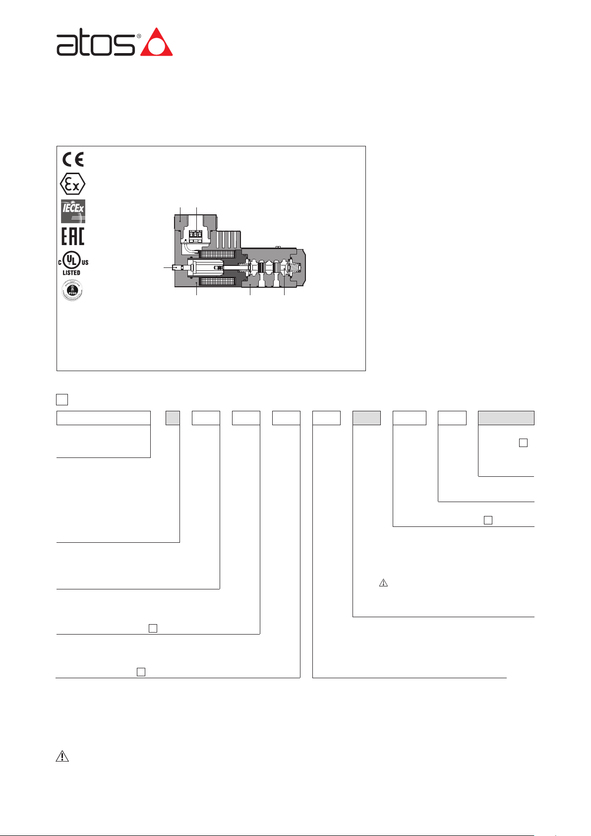
valve body
spool
ex-proof solenoid
manual override
threaded connections for cable gland
internal terminal board for cable connection
DHA
Spool type, direct operated directional
valves equipped with ex-proof solenoids
certified for safe operation in hazardous
environments with potentially explosive
atmosphere.
Certifications:
•
Multicertification ATEX, IECEx and EAC
for gas group II 2G and dust category II 2D
•
Multicertification ATEX and IECEx
for gas group I M2 (mining)
•
cULUS North American certification
for gas group C&D
DHA valves are SIL compliance with IEC
61508 (TÜV certified)
The flameproof enclosure of solenoid prevents
the propagation of accidental internal sparks
or fire to the external environment.
The solenoid is also designed to limit the
surface temperature within the classified limits.
Size: 06 - ISO 4401
Max flow: 70 l/min
Max pressure: 350 bar
A
B
Ex-proof solenoid
directional valve,
direct operated
Solenoid threaded connection for cable gland fitting:
GK = GK-1/2” - not for
CULUS
M = M20x1,5 - not for
CULUS
NPT = 1/2” NPT
1
MODEL CODE
Configuration
, see section
:
2
Spool type
, see section
:
2
Series number
Valve size (ISO 4401)
0 = 06
(1) The valves with Multicertification for Group II are also certified for Indian market according to PESO (Petroleum and Explosives Safety Organization).
The PESO certificate can be downloaded from www.atos.com
(2) Not for multicertification M group I (mining)
(3) For possible combined options, see 11.1
(4) Options MV and AMV are available only for configuration 61, 61/A, 63, 63/A, 71 and with spool type 0, 0/2, 1, 1P, 1/2, 1/2P, 3, 3P, 4, 7.
Not available in combination with option WP
Options (3):
A = solenoid at side of port B
(for single solenoid valves)
O = horizontal cable entrance (2)
WP =
manual override protected by metallic cap
Hand lever options
(4):
MV = vertical hand lever
AMV = vertical hand lever installed at side of port B
DHA
// //-
M * 24DC
** *
* 0 1/2
63
Certification type:
Multicertification ATEX, IECEx, EAC:
- = omit for Group II 2G / II 2D (1)
M = Group I M2 (mining)
North American Certification:
UL =
CULUS
Voltage code, see section
5
Seals material,
see section
:
- =
NBR
PE = FKM
BT = HNBR
(1)
6
The pressure at T port makes difficult the manual override operation that can be possible only if its value is lower than 50 bar
Table EX010-1/E
Replaces E120-28/E
E125-16/E
Page 2
2
1
2
1
02
1
0
1
71
63
61
75
67/A
63/A
61/A
67
2
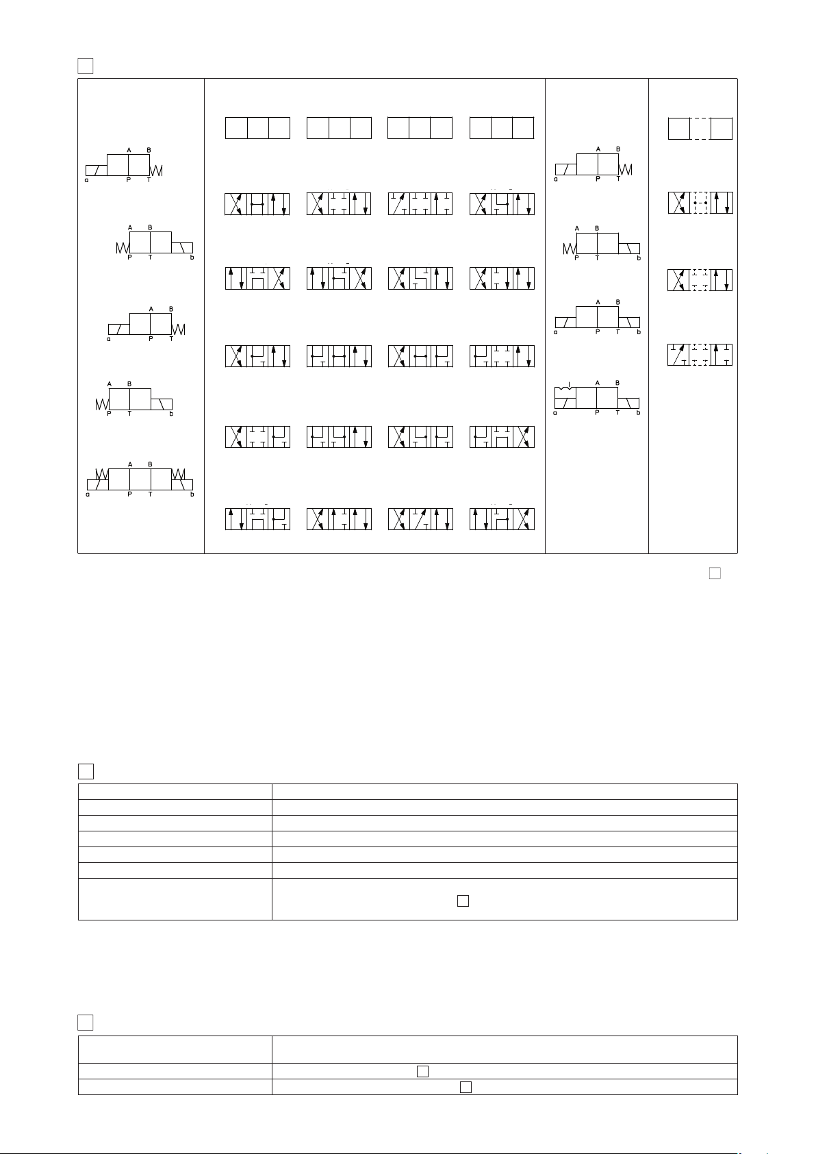
CONFIGURATIONS AND SPOOLS (representation according to ISO 1219-1)
0
8
49
1
90
16
2
09
17
3
91
58
4
19
5
93
6
39
7
94
02
02
0
1
2
1
0/2
1/2
2/2
(1)
Configurations Spools Configurations Spools
2
1
70
2.1 Special shaped spools
- spools type 0 and 3 are also available as 0/1 and 3/1 with restricted oil passages in central position, from user ports to tank.
-
spools type 1, 4, 5 and 58 are also available as 1/1, 4/8, 5/1 and 58/1.
They are properly shaped to reduce water-hammer shocks during the swiching.
- spools type 1, 1/2, 3, 8 are available as 1P, 1/2P, 3P, 8P to limit valve internal leakages.
Operating pressure
Ports P,A,B: 350 bar;
Port T 210 bar
Rated flow
See diagrams Q/Δp at section
12
Maximum flow
70 l/min, see operating limits at section
13
4
HYDRAULIC CHARACTERISTICS
For spool type 2 and 2/2 port T of the valve must be connected to tank if the operating pressure exceed the max T pressure reported at section
(1): not available for configuration 75
3
Assembly position / location Any position
Subplate surface finishing Roughness index Ra 0,4 - flatness ratio 0,01/100 (ISO 1101)
MTTFd values according to EN ISO 13849
150 years, for further details see technical table P007
Ambient temperature
Standard = -20°C ÷ +70°C /PE option = -20°C ÷ +70°C /BT option = -40°C ÷ +70°C
Storage temperature range
Standard = -20°C ÷ +80°C /PE option = -20°C ÷ +80°C /BT option = -40°C ÷ +70°C
Surface protection
Zinc coating with black passivation (body and solenoid housing)
Compliance
Explosion proof protection, see section
7
3
GENERAL CHARACTERISTICS
01 02
01 02
01 02
01 02
01 02
Page 3
EX010
7
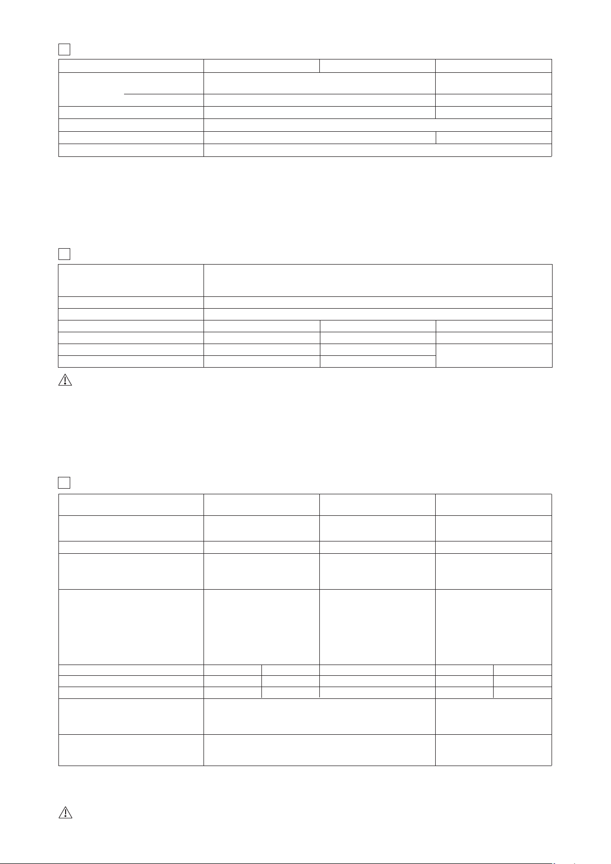
CERTIFICATION DATA
Type examination certificate (1)
Method of protection
Cable entrance: threaded connection
vertical (standard) or horizontal (option /O)
DHA
DHA/M
DHA/UL
T6
≤ 85 °C
-40 ÷ +45 °C
ATEX: CESI 02 ATEX 014
IECEx: IECEx CES 10.0010x
EAC: TC RU C-IT. 08.B.01784
ATEX: CESI 03 ATEX 057x
IECEx: IECEx CES 12.0007x
20170324 - E366100
OA
OA/M OA/EC
Multicertification Group II Multicertification Group I North American
CULUS
-
≤ 150 °C
-20 ÷ +70 °C
T4
≤ 135 °C
-40 ÷ +70 °C
T6
-40 ÷ +55 °C
T5
-40 ÷ +70 °C
Valve type
Solenoid certified code
UL 1203 and UL429,
CSA 22.2 n°30-1986
CSA 22.2 n°139-13
Temperature class
Surface temperature
Ambient temperature
(2)
≤ 85 °C ≤ 100 °C
ATEX IECEx EAC
CULUS
Certifications
ATEX IECEx
• ATEX 2014/34/EU
Ex I M2 Ex db I Mb
• IECEx
Ex db I Mb
• ATEX 2014/34/EU
Ex II 2G Ex d IIC T6/T4/T3 Gb
Ex II 2D Ex tb IIIC T85°C/T200°C Db
• IECEx
Ex d IIC T6/T4/T3 Gb
Ex tb IIIC T85°C/T200°C Db
• EAC
Ex II 2G Exd IIC T6/T4
• UL 1203
Class I, Div.I, Groups C & D
Class I, Zone I, Groups IIA & IIB
GK = GK-1/2”
M = M20x1,5
NPT = 1/2” NPT
1/2” NPT ANSI/ASME B46.1
5
ELECTRICAL CHARACTERISTICS
(1) For alternating current supply a rectifier bridge is provided built-in the solenoid
For power supply frequency 60 Hz, the nominal supply voltage of solenoids 110AC and 230AC must be 115/60 and 240/60 respectively
Coil insulation
VAC 50/60 Hz ±10%
Voltage code (1)
V
DC
±10%
Duty factor
Power consumption at 20°C
Protection degree with relevant cable gland
DHA
DHA/M
DHA/UL
Valve type
12DC, 24DC, 28DC, 48DC, 110DC, 125DC, 220DC
12DC, 24DC, 110DC,
125DC, 220DC
12AC, 24AC, 110AC, 230AC
12AC, 24AC, 110AC, 230AC
8W
12W
class H
IP66/67 to DIN EN60529
raintight enclosure, UL approved
100%
Seals, recommended fluid temperature
NBR seals (standard) = -20°C ÷ +60°C, with HFC hydraulic fluids = -20°C ÷ +50°C
FKM seals (/PE option) = -20°C ÷ +80°C
HNBR seals (/BT option) = -40°C ÷ +60°C, with HFC hydraulic fluids = -40°C ÷ +50°C
Recommended viscosity 15÷100 mm2/s - max allowed range 2.8 ÷ 500 mm2/s
Max fluid contamination level ISO4406 class 20/18/15 NAS1638 class 9, see also filter section at www.atos.com or KTF catalog
Hydraulic fluid Suitable seals type Classification Ref. Standard
Mineral oils NBR, FKM, HNBR HL, HLP, HLPD, HVLP, HVLPD DIN 51524
Flame resistant without water FKM HFDU, HFDR
ISO 12922
Flame resistant with water NBR, HNBR HFC
6
SEALS AND HYDRAULIC FLUIDS - for other fluids not included in below table, consult our technical office
(1) Performance limitations in case of flame resistant fluids with water:
-max operating pressure = 210 bar
-max fluid temperature = 50°C
The ignition temperature of the hydraulic fluid must be 50°C higher than the max solenoid surface temperature.
(1) The type examinator certificates can be downloaded from www.atos.com
(2) The solenoids Group II and CULUS are certified for minimum ambient temperature -40°C
In case the complete valve must withstand with minimum ambient temperature of -40°C, select /BT in the model code
WARNING: service work performed on the valve by the end users or not qualified personnel invalidates the certification
Applicable standards
EN 60079-0: 2012+A11:2013
EN 60079-1:2014
EN 60079-31:2014
IEC 60079-0:2017
IEC 60079-1:2017-04
IEC 60079-31:2013
Page 4
10
CABLE GLANDS only for Multicertification
Cable glands with threaded connections GK-1/2”, 1/2”NPT or M20x1,5 for standard or armoured cables have to be ordered separately,
see tech. table KX600
Note: a Loctite sealant type 545, should be used on the cable gland entry threads
Max ambient temperature [°C]
Temperature class
Group I Group II
Max surface temperature [°C]
Group I Group II
Min cable temperature
45 °C not prescribed
70 °C 90 °C
Max ambient temperature [°C] Temperature class Max surface temperature [°C] Min cable temperature
55 °C T6 85 °C 100 °C
70 °C T5 100 °C 100 °C
CULUS certification
Multicertification
9
CABLE SPECIFICATION AND TEMPERATURE - Power supply and grounding cables have to comply with following characteristics:
9.1 Cable temperature
The cable must be suitable for the working temperature as specified in the “safety instructions” delivered with the first supply of the products.
Power supply: section of coil connection wires = 2,5 mm
2
Grounding: section of internal ground wire = 2,5 mm
2
section of external ground wire = 4 mm
2
Multicertification Group I and Group II
cULus certification:
• Suitable for use in Class I Division 1, Gas Groups C
• Armored Marine Shipboard Cable which meets UL 1309
• Tinned Stranded Copper Conductors
• Bronze braided armor
• Overall impervious sheath over the armor
Any Listed (UBVZ/ UBVZ7) Marine Shipboard Cable rated 300 V min, 15A min. 3C 2,5 mm
2
(14 AWG) having a suitable service temperature
range of at least -25°C to +110°C (“/BT” Models require a temperature range from -40°C to +110°C)
Note 1: For Class I wiring the 3C 1,5 mm
2
AWG 16 cable size is admitted only if a fuse lower than 10 A is connected to the load side of the
solenoid wiring.
85 °C
135 °C
150 °C
150 °C
T6
T4
-
-
1 = Coil
2 = GND
3 = Coil
PCB 3 poles terminal board
suitable for wires cross sections
up to 2,5 mm
2
(max AWG14)
8
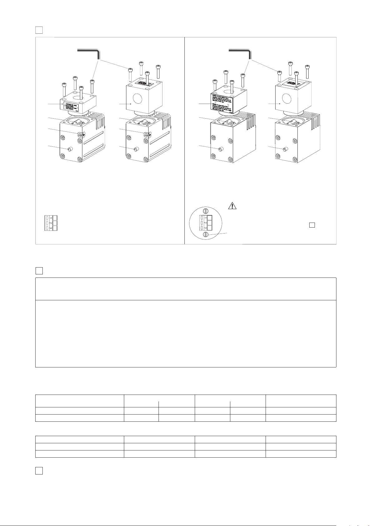
EX PROOF SOLENOIDS WIRING
Standard version
Option /O
cover with threaded connection for vertical cable gland fitting
cover with threaded connection for horizontal cable gland fitting
terminal board for cables wiring
standard manual override
screw terminal for additional equipotential grounding
Multicertification
C
UL
US
certification
Standard version
Option /O
cover with threaded connection for vertical cable gland fitting
cover with threaded connection for horizontal cable gland fitting
terminal board for cables wiring
standard manual override
1 = Coil +
2 = GND
3 = Coil -
alternative GND screw terminal
connected to solenoid housing
Pay attention to coil polarity
PCB 3 poles terminal board suggested cable section up to 1,5 mm
2
(max AWG16), see section note 1
9
3
n°4 M4
locking torque 4Nm
3
n°4 M4
locking torque 4Nm
Page 5
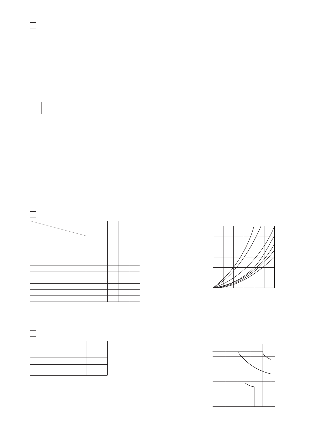
12
Q/Δp DIAGRAMS (based on mineral oil ISO VG 46 at 50°C)
Valve pressure drop Δp [bar]
Flow rate [l/min]
GF
E
D
C
B
A
Flow rate [l/min]
Inlet pressure [bar]
C
A
B
13
OPERATING LIMITS (based on mineral oil ISO VG 46 at 50°C)
0, 0/1, 1, 1/1, 8
0/2,1/2, 3, 6, 7
3/1, 4, 4/8, 5, 5/1, 16, 17, 19, 39
49, 58, 58/1, 09, 90, 91, 93, 94
A
B
C
Spool type
diagram
Flow direction
Spool type
P씮A P씮B A씮T B씮T P씮T
0, 0/1 A A C C D
1, 1/1 D C C C
3, 3/1
D D A A
4, 4/8, 5, 5/1, 49, 58, 58/1, 94 F F G C E
1/2, 0/2 D D D D
6, 7, 16, 17 D D D D
8 A A E E
2 D D
2/2 F F
09, 19, 90, 91 E E D D
39, 93 F F G G
24
20
16
12
8
4
0
0 15 30 45 60 75 90
400
320
240
160
80
0
0 15 30 45 60 75
11
OPTIONS
A = solenoid at side of port B (for single solenoid valves)
O = Horizontal cable entrance , to be selected in case of limited verical space
WP = Manual override protected by metallic cap
11.1 Possible combined options: /AO, /AWP, /OWP, /AMV, /OMV, /AOWP, /AOMV
Total angle stroke [°deg] ± 28°
Working angle stroke [°deg] ± 15°
Lever actuating force [N] 1 ÷ 8
Lever device weight [g] 880
Hand lever option:
MV = Auxiliary vertical hand levers
This option allows to operate the valves in absence of electrical power supply, i.e. during commissioning, maintenance or in case of
emergency.
When the valve is electrically operated the hand lever remains stopped in its rest position
The hand lever execution does not affect the performances of the original valves
EX010
AMV=Vertical hand lever installed at side of port B
Notes:
Options MV and AMV are available only for configuration 61, 61/A, 63, 63/A, 71 and with spool type 0, 0/2, 1, 1P, 1/2, 1/2P, 3, 3P, 4, 7
Not available in combination with option WP
MV option
and AMV
allow to operate the valve in absence of electrical power supply.
For detailed description of DHA with hand lever option see tech. table E138
Page 6
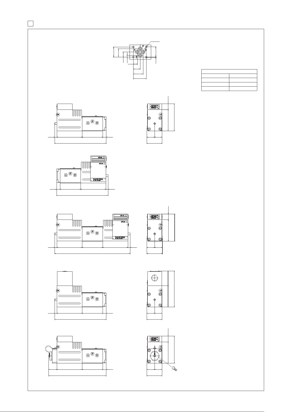
14
INSTALLATION DIMENSIONS [mm] - Multicertified and UL
ISO 4401: 2005 (see table P005)
Mounting surface:
4401-03-02-0-05
Fastening bolts: 4 socket head screws:
M5x50 class 12.9
Tightening torque = 8 Nm
Seals: 4 OR 108
Ports P,A,B,T: Ø = 7.5 mm (max)
P = PRESSURE PORT
A, B = USE PORT
T = TANK PORT
ø5.5
40.5
30.2
21.5
12.7
31
25.9
15.5
5.1
0.75
31.75
164.5
66 1180.57
49
25 24
68.5
87
18.5
241
6680.57 80.5 7
164.5
6680.5711
184
6680.526.5 11
164.5
6611 80.5 7
50
25 25
68.5
87
18.5
49
25 24
68.5
115.5
47
49
25 24
68.5
87
18.5
98.5
for UL
30 for UL
98.5
for UL
30 for UL
98.5
for UL
30 for UL
DHA-06 /A
DHA-06
DHA-07
DHA-06 /O
DHA-06 /WP
27
Valve’s bottom view
Mass [kg]
DHA-06 2,65
DHA-07 4,3
Option /O +0,35
Option /WP +0,25
Page 7
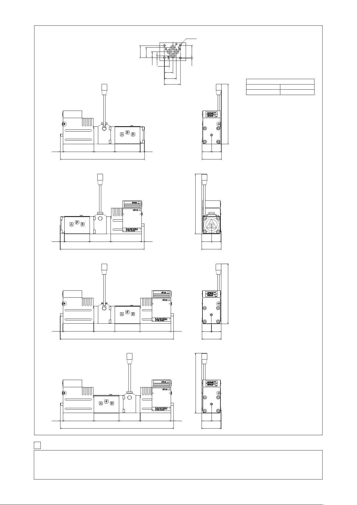
ISO 4401: 2005 (see table P005)
Mounting surface:
4401-03-02-0-05
Fastening bolts: 4 socket head screws:
M5x30 class 12.9
Tightening torque = 8 Nm
Seals: 4 OR 108
Ports P,A,B,T: Ø = 7.5 mm (max)
P = PRESSURE PORT
A, B = USE PORT
T = TANK PORT
ø5.5
40.5
30.2
21.5
12.7
31
25.9
15.5
5.1
0.75
31.75
219.5
55 1180.57
51
25 26
157
66
219.5
55 780.511 66
304
66 1180.555
304
55 1180.56611 80.5
11 80.5
DHA-06 /MV
DHA-06 /AMV
DHA-07 /MV
DHA-07 /AMV
51
26 25
157
51
25 26
157
51
26 25
157
01/19
Valve’s bottom view
Mass [kg]
DHA-06/MV 2,9
DHA-07/MV 4,55
15
RELATED DOCUMENTATION
X010 General guideline for ex-proof components
TT291 Safety instruction for Multicertification Atex, IECEx, EAC - Group II
TT354 Safety instruction for Multicertification Atex, IECEx - Group I Mining
KX600 Cable glands for ex-proof valves
P005 Mounting surfaces for electrohydraulic valves
 Loading...