

Page 1
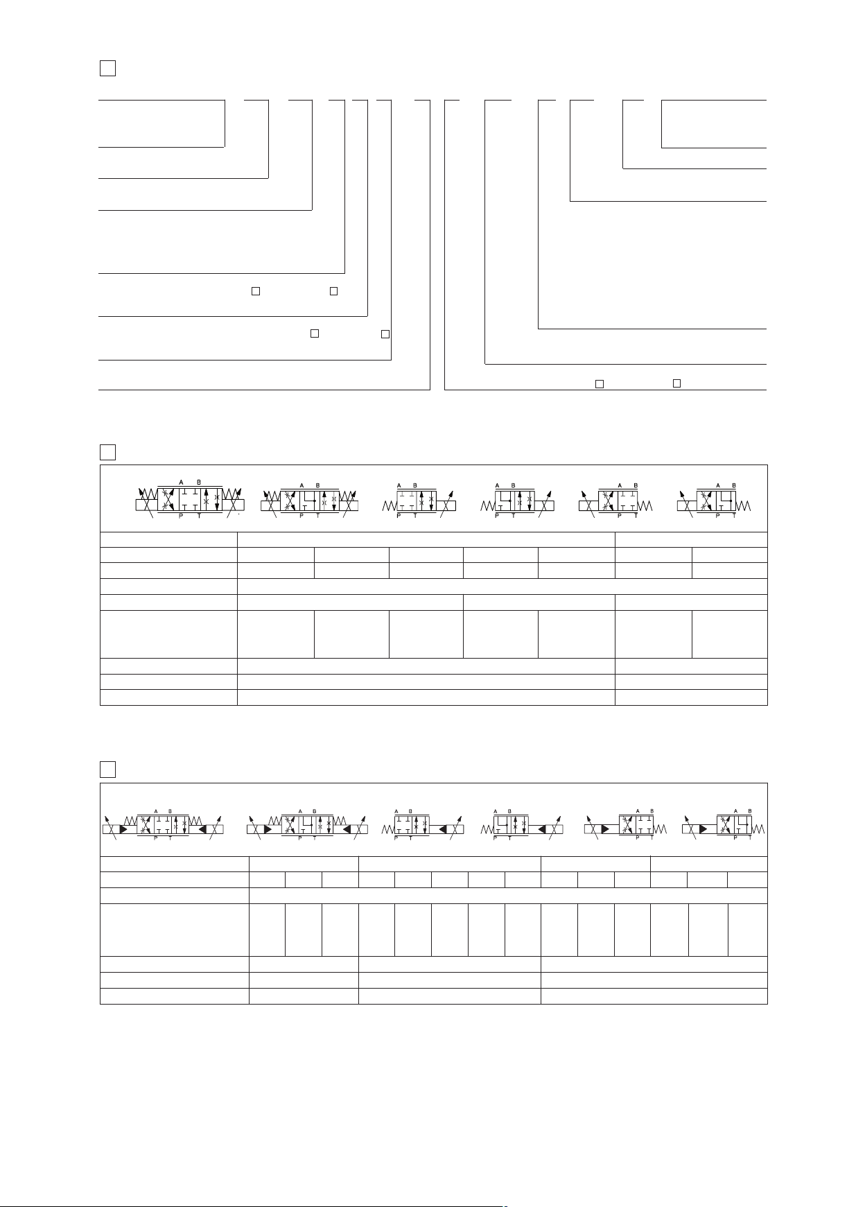
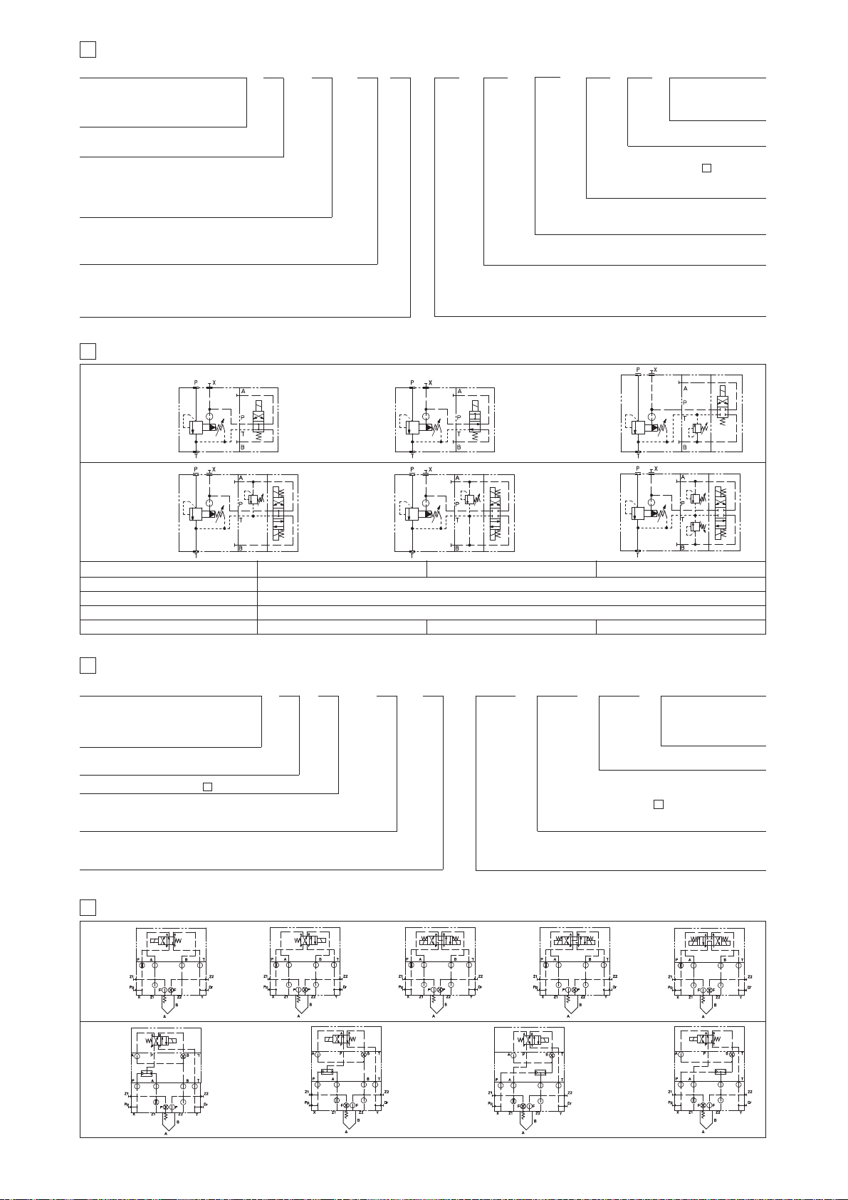
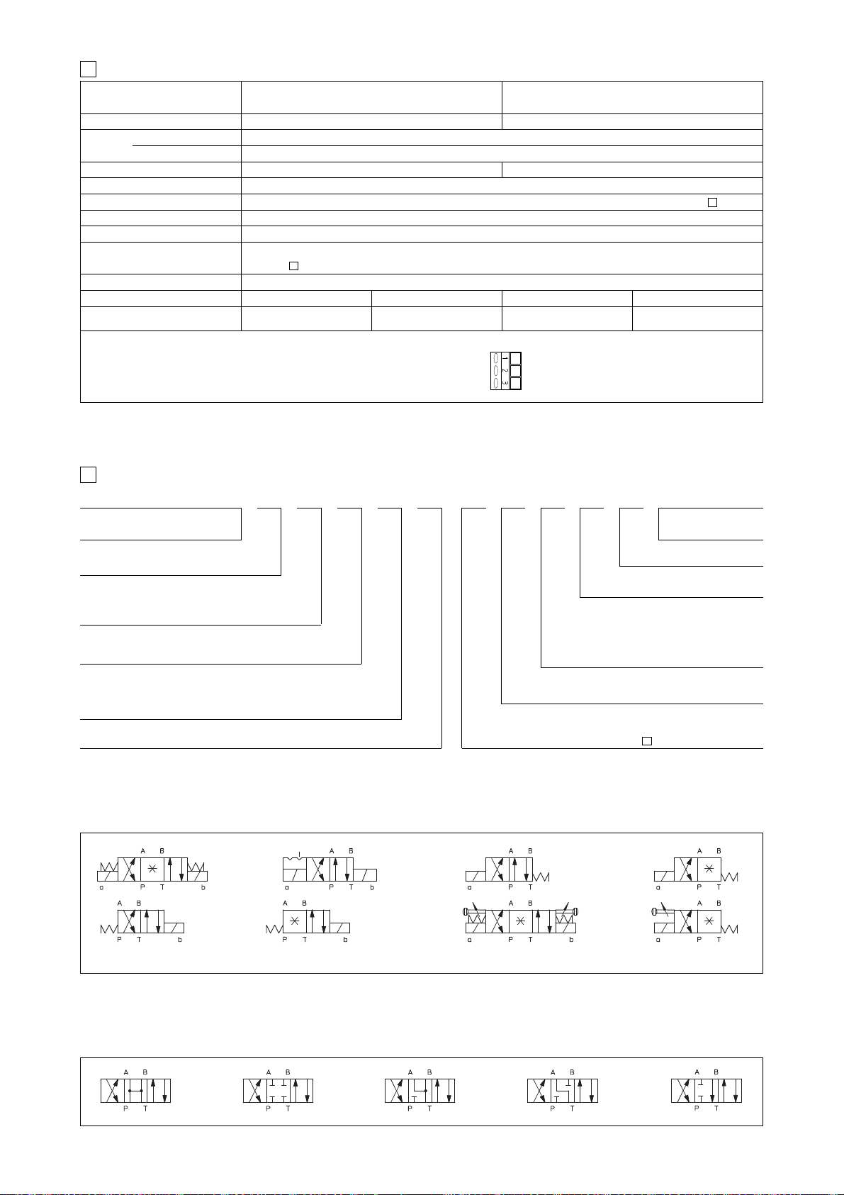
5 MODEL CODE OF PROPORTIONAL DIRECTIONAL VALVES
1
DHZA
DHZA = size 06
DKZA = size 10
DPZA = size 10
= size 16
= size 25
L = C UL US certification
U
A = without integral position transducer
T = with integral position transducer (not for DPZA)
Valve size (ISO 4401)
DHZA DKZA DPZA
= size 06 1= size 10 1= size 10
0
2= size 16
4= size 25
6= size 32
onfiguration, DHZA and DKZA see section , DPZA see section
C
5 =
external plus central position, spring centered
7 = 3 position, spring centered
pool overlapping in central position, DHZA and DKZA see section , DPZA see section
S
= P, A, B, T positive overlapping
1
3 = P positive overlapping; A, B, T, negative
pool type
S
L = linear; S = progressive; D = as S, but with P-A = Q, P-B = Q/2
(1)
Option /BT = low temperature -40°C also available on request
(2) Option /MV Available only for DHZA configuration 51, 53, 71, spool type S3, S5, D3, D5, L3, L5
HYDRAULIC CHARACTERISTICS of DHZA and DKZA (based on mineral oil ISO VG 46 at 50 °C)
16
ydraulic symbols
H
71, *71/B *73, *73/B *51 *53 *51/B *53/B
*
/UL T
16
07 -
17
6
1
1
17
L5/
NPT
Solenoid threated connection:
NPT = 1/2” NPT ANSI/ASME B46.1 (tapered)
Spool size:
*
/
DHZA and DKZA see section , DPZA see section
/*
mit for standard coil 12 V
O
24 = with 24 V
B = solenoid at side of port A (only for single solenoid
valves)
C = position transducer with current feedback 4÷20 mA
only for -T)
(
D = internal drain (only for DPZA)
E
= external pilot (only for DPZA)
G
= pressure reducing valve for piloting
(only for DPZA)
MV = vertical hand lever
O = horizontal cable entrance
WP
=
prolongued manual override protected
by
m
external drain (only for DHZA and DKZA)
=
Y
** /*- -
/
Series number
DC c
Options:
2)
(
etallic cap (only for -A)
6
1
oils (only A version)
Seals material (1):
omit for NBR (mineral oil &
ater glycol)
w
PE = FPM
:
DC
(only for -A)
17
a b
Valve model
pool overlapping
S
Spool type and size
a
b b b
DHZA-A DHZA-T
, 3 1, 3 1, 3 1, 3 1, 3
1
14 L1
L
, 3
1
3, L3, D3
S2
S
a
5, L5, D5 S3, L3, D3 S5, L5, D5
S
Pressure limits [bar] ports P, A, B = 350; T = 160 (250 with external drain /Y)
D
p max P-T [bar]
5070
Max flow [l/min]
D
p = 10 bar (P-T)
at
at
D
p = 30 bar (P-T)
max permissible flow
Response time (1) [ms]
Hysteresis [%]
Repeatability
(1) Response times at step signal (0%→100%) are measured from 10% to 90% of step value and are strictly referred to the valve regulation
HYDRAULIC CHARACTERISTICS OF DPZA (based on mineral oil ISO VG 46 at 50 °C)
17
1
2
3
4,5
8
12
< 30 (A)
≤ 5% (A)
± 1% (A)
8
14
21
< 15 (T)
≤ 0,2% (T)
± 0,1% (T)
17
30
45
28
50
60
Hydraulic symbols
*71, *71/B
aa b
Valve model
Spool type and size (1)
Pressure limits
[bar]
DPZA-1
S5 D5 S3 D3 L5 S5 D5
Ports P, A, B, X = 350; T = 250; Y = 0
*73
b
*51
DPZA-2
b
*53
L5
a
DPZA-4
S5 D5 L5 S5 D5L5
Max flow [l/min]
160:98
100
100
D
p = 10 bar
at
D
p = 30 bar
at
max permissible flow
160
180
Response time (2) [ms]
Hysteresis [%]
Repeatability
(1) Additional spools and configurations for -T execution, see table F172.
(2) Response times at step signal (0%→100%) are measured from 10% to 90% of step value and are strictly referred to the valve regulation
160
180
< 80
£ 5%
± 1%
100 : 60
160 : 100
180 : 110
160
270
400
270:160
400:245
250
430
550
< 100
£ 5%
± 1%
225
390
550
225 : 160
390 : 280
550 : 390
420
720
900
400
690
900
400 : 245
690
900 : 550
a
DKZA-A DKZA-T
40
45
80
90
< 40 (A)
≤ 5% (A)
± 1% (A)
*51/B
600
:
420
1000
1600
< 120
£ 5%
± 1%
< 20 (T)
≤ 0,2% (T)
± 0,1% (T)
ab
DPZA-6
600
1000
1600
1, 3
60
105
120
*53/B
600:370
1000:620
1600:990
ELECTRONIC DRIVERS TO BE USED WITH EX-PROOF PROPORTIONAL VALVES
- Atos driver for proportional valves type -A (without transducer): E-ME-AC, see tab. G035
- Atos driver for proportional valves type -T (with transducer): E-ME-T, see tab. G140
E125
Page 2
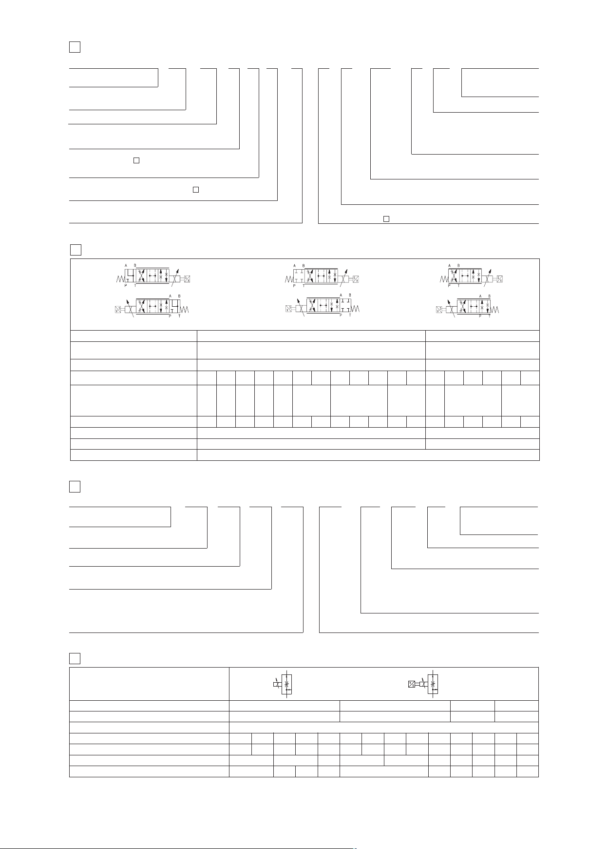
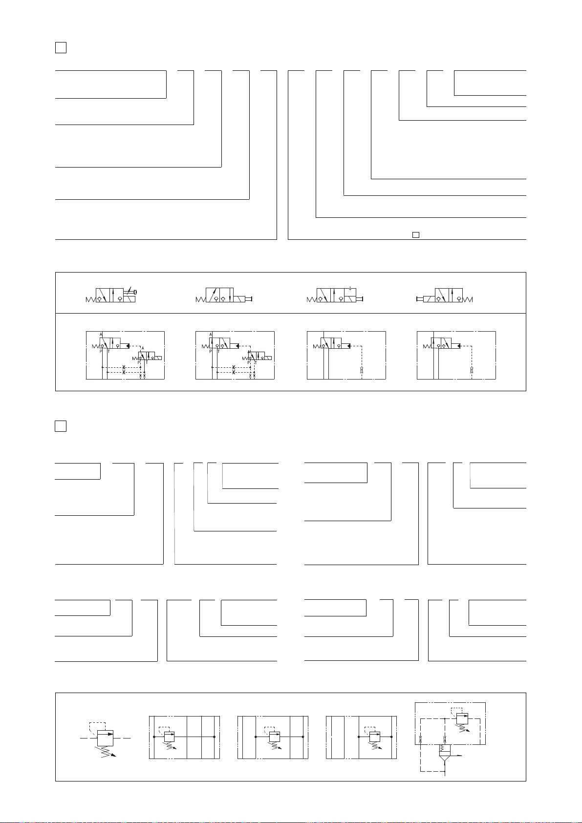
8 MODEL CODE OF SERVOPROPORTIONAL VALVES
1
DLHZA
DLHZA = size 06
DLKZA = size 10
UL = C UL US certification
= with integral position transducer
T
Valve size (ISO 4401)
= size 06 (DLHZA)
0
1 = size 10 (DLKZA)
Configuration, see section
4 =
spring offset with fail safe
6 = spring offset
Spool overlapping in central position, see section
0 = P, A, B, T zero overlapping
Spool type
L = linear; T = not linear;
(1) Option /BT = low temperature -40°C also available on request
YDRAULIC CHARACTERISTICS (based on mineral oil ISO VG 46 at 50 °C)
H
9
1
Hydraulic
ymbols
s
*40-L*3/B
*40-D*3/B
40-DT*3/B
*
*40-T*3/B
40-V*3/B
*
9
1
a
/UL T
19
*40-L*3
*40-D*3
40-DT*3
*
b
*40-T*3
40-V*3
*
04 -
0
*40-L*1/B
40-D*1/B
*
*40-DT*1/B
40-T*1/B
*
*40-V*1/B
Valve model
ressure limits [bar]
P
= 160 (250 with external drain /Y)
T
Dp max P-T
Spool
ax flow [l/min]
M
t Dp = 30 bar
a
max permissible flow
Leakage [cm
3
/min] at P = 100 bar (
1)
1 V1 L3 V3 L5 T5 L7 T7 V7 D7 DT7 L3 L7 T7 V7 D7 DT7
0
L
L
2,5
4,575891413
4
<200
<100 <100 <150 <200 <200<700
<300 <500
Response time [ms]
Hysteresis [%]
Thermal drift
(1) Referred to spool in center position and 50°C oil temperature.
L7 /
pool size: see section
S
NPT
3
olenoid threated connection:
S
NPT = 1/2” NPT ANSI/ASME B46.1 (tapered)
Fail safe configuration:
A, B, P, T with positive overlapping 3 = P, positive overlapping; A, B, T negative
1 =
*40-L*1
*40-D*1
40-DT*1
*
b
*40-T*1
40-V*1
*
a
LHZA-T*
D
orts P, A, B = 350;
p
70
18
20
28
26
40
<200 <900 <200
≤ 10
≤ 0,1%
zero point displacement < 1% at DT = 40°C
/
19
26÷13
40÷204055
*
** /*- -
Seals material (1):
mit for NBR (mineral oil &
o
water glycol)
PE = FPM
eries number
S
Options:
B = solenoid at side of port A
C = position transducer with current feedback
4÷20 mA
Y = external drain
60-L*1
*
*60-V*1
b
*60-L*1/B
*60-V*1/B
a
LKZA-T*
D
ports P, A, B =
250 with external drain /Y)
= 160
(
T
65
80
<1000 <1500 <400
315;
0
6
65÷33
80÷40
<1200
<400 <400
≤ 15
≤ 0,1%
MODEL CODE OF PRESSURE COMPENSATED PROPORTIONAL FLOW CONTROL VALVES
20
QVHZA
QVHZA = size 06
QVKZA = size 10
UL = C UL US certification
A = without position transducer
T = with integral position transducer
Valve size (ISO 4401)
QVHZA: 06
Max regulated flow:
3 = 3,5 l/min;
12 = 12 l/min
18 = 18 l/min;
(1) Option /BT = low temperature -40°C also available on request
21
QVHZA
HYDRAULIC CHARACTERISTICS (based on mineral oil ISO VG 46 at 50 °C)
QVKZA: 10
36 = 36 l/min;
45 = 45 l/min;
UL/--
T 06
QVKZA
65 = 65 l/min
90 = 90 l/min
Hydraulic symbols
Note: In three-way versions port P is open.
In two-way versions port P must be plugged.
Port T must always be plugged.
Valve model
Valve size
Max pressure ports P, A, B [l/min]
Max regulated flow [l/min]
Min regulated flow (1) [cm
3
Regulating Dp [bar]
Max flow on port A [l/min]
Above performance data refer to valves coupled with Atos electronic drivers.
(1) Values are referred to 3-way configuration. In the 2-way configuration, the values of min regulated flow are higher
3,5 12 18
/min]
15 20 30 50 60 15 20 30 50 60 85 85 100
4 - 6 10 - 12 15 4 - 6 10 - 12 15606 - 8 6 - 8 10 - 12
40 35 50
12/ / NPT
Solenoid threated connection:
NPT = 1/2” NPT ANSI/ASME B46.1 (tapered)
B
QVHZA-A
P
A
QVHZA-A QVHZA-T QVKZA-A QVKZA-T
QVKZA-A
*
/
Options:
C = current feedback signal 4÷20 mA (only for -T versions)
D = quick venting
O = horizontal cable entrace (only for -A versions)
prolongued manual override protected by
WP=
(only for valves without transducer)
06 06
210
45
36 3,5 65
55
12 18 35 45 65 90
50
/*
Omit for standard coil 12 VDC:
24 = with 24 V
**
Series number
DC coils (only A version)
B
P
A
70 10070
/*
Seals material (1):
omit for NBR (mineral oil &
water glycol)
PE = FPM
metallic cap
QVHZA-T
QVKZA-T
10
90
100
10 - 12
100
10
Page 3
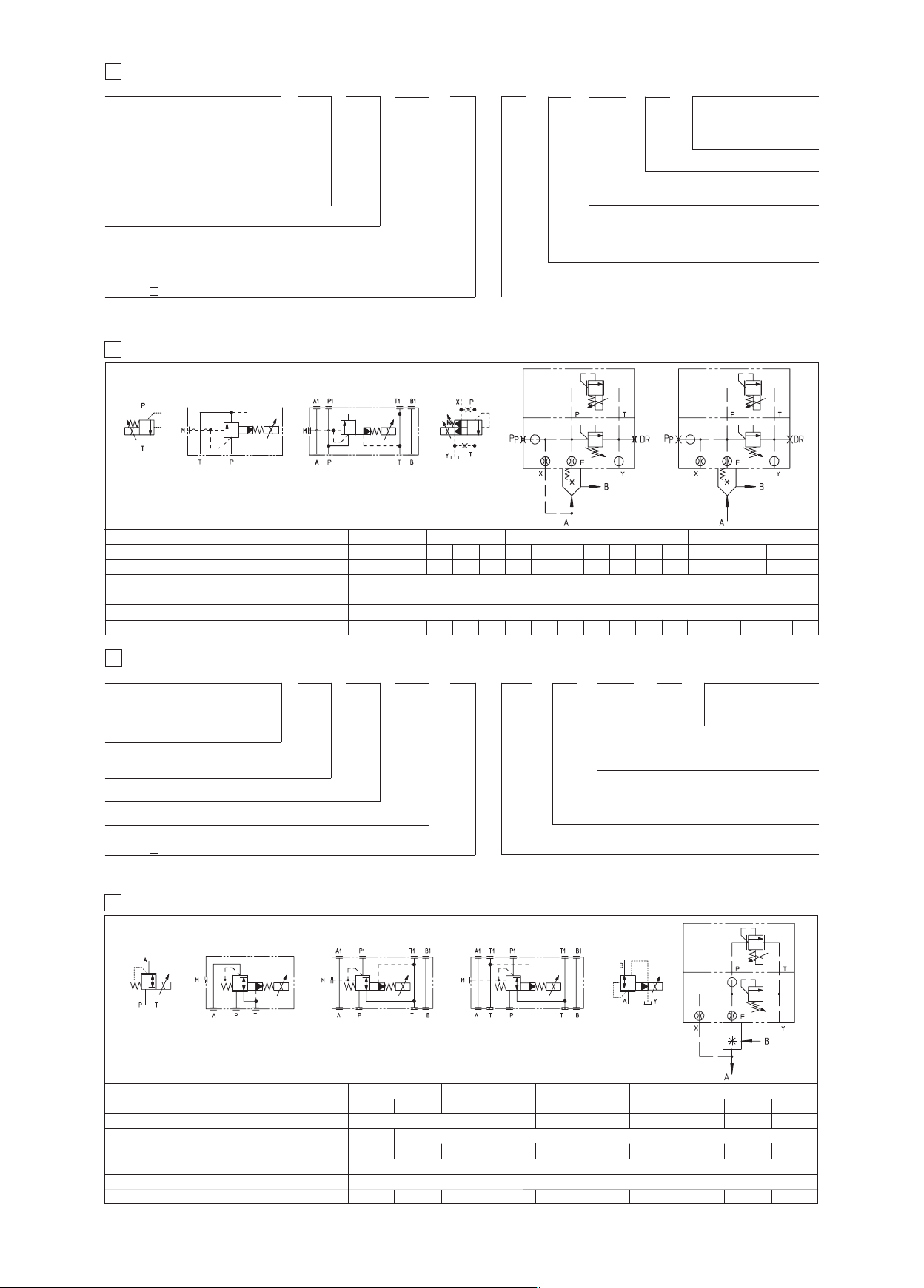
2 MODEL CODE OF PROPORTIONAL PRESSURE RELIEF AND COMPENSATOR VALVES
2
––
RZMA
ressure relief:
P
RZMA = subplate size 06
HZMA = modular size 06
AGMZA= subplate size 10, 20, 32
LIMZA = cartridge
ressure compensator:
P
ICZA = cartridge
L
L = C UL US certification
U
A = without integral pressure transducer
Valve size:
ee section for size code
s
ax regulated pressure:
M
see section
1) For the code of the ISO cartridge to use with LIMZA and LICZA, see tab. F300 section
(
(1)
1)
(
23
23
UL/
A
010
250
/
NPT/
olenoid threated connection:
S
PT = 1/2” NPT ANSI/ASME B46.1 (tapered)
N
쪨
.
(2) Option /BT = low temperature -40°C also available on request
YDRAULIC CHARACTERISTICS
H
23
ZMA-010 HZMA
R
RZMA-030
GMZA
A
/
*
Options:
= external pilot (only for AGMZA)
E
= horizontal cable entrace
O
=
P
= external drain (only for AGMZA)
Y
/*
Omit for standard coil 12 VDC:
24 = with 24 V
ith integral mechanical pressure limiter (only for LI*ZA)
w
**
eries number
S
DC coils (only A version)
/*
Seals material (2):
omit for NBR (mineral oil &
ater glycol)
w
PE = FPM
Valve model
Size code
alve size
V
RZMA HZMA AGMZA LIMZA LICZA
010 030 030 10 20 32 123456 12345
6 10 20 32
0
Max regulated pressure [bar]
Max pressure at port P, A, B, X [bar]
ax pressure at port T, Y [bar]
M
Max flow [l/min]
4 40 40 200 400 600 200 400 750 1000 2000 3000 200 400 750 1000 2000
24 MODEL CODE OF PROPORTIONAL PRESSURE REDUCING VALVES
––
RZGA
Pressure reducing:
RZGA = subplate size 06
HZGA = modular size 06
KZGA = modular size 10
AGRCZA = subplate size 10, 20
LIRZA = cartridge
UL = C UL US certification
A = without integral transducer
Valve size:
25
see section for size code
Max regulated pressure:
25
see section
AUL/
Note: for the code of the ISO cartridge to use with LIRZA, see tab. F300 section
010
/
쪨
(1) Option /BT = low temperature -40°C also available on request
HYDRAULIC CHARACTERISTICS
25
250
.
LIMZA
16 25 32 40 50 63
0; 180; 250
8
15
3
210
NPT/ ** /**
/
Options:
O = horizontal cable entrace (1)
P = with integral mechanical pressure limiter
(only for AGRCZA and LIRZA)
R = with check valve (only for AGRCZA)
Solenoid threated connection:
NPT = 1/2” NPT ANSI/ASME B46.1 (tapered)
/*
Omit for standard coil 12 V
24 = with 24 V
8
80
4500
Series
number
DC coils (only A version)
ICZA
L
16 25 32 40 50
eals material (1):
S
omit for NBR (mineral oil &
water glycol)
PE = FPM
:
DC
RZGA-A-010 KZGA-A-031
Valve model
Size code
Valve size
Max regulated pressure [bar]
Min regulated pressure [bar]
RZGA-A-033
HZGA-A-031
RZGA HZGA
010 033 031 10 20
32; 100; 210
0,8
06 10 2010
80; 180; 250
11 111
KZGA
031
Max pressure at port P [bar]
Max pressure at port T [bar]
Max flow [l/min]
12
40 40 160 300100
AGRCZA-A
AGRCZA LIRZA
25 3216
777
315
210
160
300 550
321
LIRZA-A
4
40
7
800
E125
Page 4
6
2
X
E
S
F
O
O
R
P
4
M
r
o
t
g
n
i
k
c
o
l
D
I
O
N
E
L
O
a
F
F
O
-
N
O
3
H
C
m
N
4
e
u
q
G
N
I
R
I
W
S
A
-
s
e
v
l
a
v
l
a
n
o
i
t
r
o
p
o
r
p
d
n
4
M
o
t
g
n
i
k
c
o
l
o
r
P
3
H
C
m
N
4
e
u
q
r
l
a
n
o
i
t
r
o
p
T
-
s
e
v
l
a
v
C
P
•
•
•
•
•
A
e
t
F
s
N
n
o
i
s
r
e
v
d
r
a
d
n
a
t
S
f
n
o
i
t
c
e
n
n
o
c
d
e
d
a
e
r
h
t
h
t
i
w
r
e
v
o
c
n
o
c
d
e
d
a
e
r
h
t
h
t
i
w
r
e
v
o
c
e
l
b
a
c
r
o
f
d
r
a
o
b
l
a
n
i
m
r
e
t
n
a
m
d
r
a
d
n
a
t
s
a
c
i
f
i
c
e
p
S
e
l
b
a
r
e
w
o
a
t
i
u
S
m
r
A
n
n
i
T
o
r
B
e
v
O
s
i
L
y
n
r
e
p
m
a
l
C
r
o
o
n
e
l
o
a
:
e
t
o
n
a
y
l
p
p
u
s
s
u
r
o
f
e
l
b
i
r
a
M
d
e
r
o
n
i
d
n
a
r
t
S
d
e
d
i
a
r
b
e
z
r
e
p
m
i
l
l
a
r
V
B
U
(
d
e
t
n
a
r
e
r
u
t
a
n
i
r
i
w
I
s
s
.
g
n
i
r
i
w
d
s
e
t
i
t
c
o
L
i
r
r
e
v
o
l
a
u
C
=
1
G
=
2
C
=
3
l
a
=
)
2
(
o
c
:
n
o
i
t
u
d
s
n
a
r
t
d
s
s
a
l
C
n
i
e
o
b
p
i
h
S
e
n
p
p
o
C
d
e
r
o
m
r
a
d
e
e
h
s
s
u
o
i
v
7
Z
V
B
U
/
Z
e
l
t
a
f
o
e
g
1
C
3
e
h
t
g
p
y
t
t
n
a
l
a
e
f
n
o
i
t
c
e
n
g
n
i
r
i
w
s
e
d
+
l
i
o
C
P
D
N
u
s
p
u
-
l
i
o
G
e
v
i
t
a
n
r
e
t
o
t
d
e
t
c
e
n
n
e
l
b
a
c
r
e
c
o
i
s
i
v
i
D
I
l
b
a
C
d
r
a
u
d
n
o
C
r
e
t
r
e
v
o
h
t
a
e
n
i
r
a
M
)
C
°
5
2
-
t
s
a
2
A
m
m
5
,
h
s
,
5
4
5
e
O
l
a
c
i
t
r
e
v
r
o
o
t
i
N
s
n
e
c
h
S
W
o
t
n
o
z
i
r
o
h
r
e
l
o
p
3
B
w
r
o
f
e
l
b
a
m
m
5
,
2
o
t
t
w
e
r
c
s
D
h
d
i
o
n
e
l
o
s
o
t
e
v
a
h
G
s
a
G
,
1
m
h
c
i
h
w
s
r
o
t
r
o
m
r
a
e
d
r
a
o
b
p
i
h
C
°
0
1
1
+
o
t
a
c
6
1
G
s
u
e
b
d
l
u
O
/
n
o
i
t
p
g
n
i
t
t
i
f
d
n
a
l
g
e
l
b
a
c
r
o
f
n
o
i
t
c
e
n
n
o
c
d
e
d
a
e
r
h
t
h
t
i
w
r
e
v
o
c
d
i
o
n
e
l
o
s
g
n
i
t
t
i
f
d
n
a
l
g
e
l
b
a
c
l
g
e
l
b
a
c
r
o
f
n
o
i
t
c
e
n
n
o
c
d
e
d
a
e
r
h
t
h
t
i
w
r
e
v
o
c
r
e
c
u
d
s
n
a
r
t
g
n
i
t
t
i
f
d
n
a
l
g
e
l
b
a
c
l
a
g
n
i
r
i
w
s
e
l
b
a
c
r
o
f
d
r
a
o
b
l
a
n
i
m
r
e
t
d
i
o
n
e
l
o
s
l
b
a
c
r
o
f
d
r
a
o
b
l
a
n
i
m
r
e
t
r
e
c
u
d
s
n
a
r
t
g
n
i
r
i
w
s
e
g
n
i
t
t
i
f
d
n
a
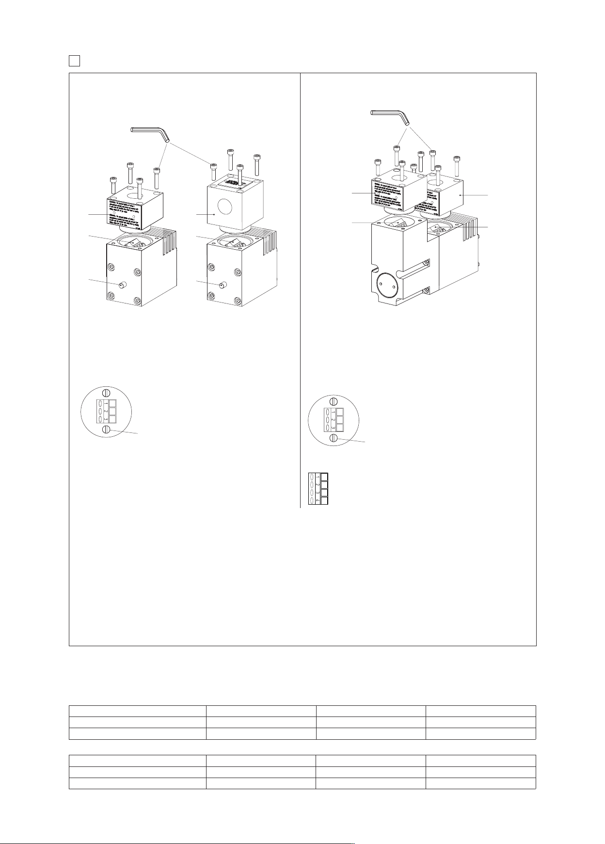
Solenoid wiring
s
s
s
o
r
c
s
e
r
i
2
W
A
x
a
m
(
l
a
n
i
m
r
e
g
n
i
s
u
o
s
n
o
i
t
c
e
s
)
4
1
G
(
+
l
i
o
C
=
1
G
=
2
C
=
3
l
a
=
)
2
o
c
C
P
D
N
o
t
i
u
s
p
u
-
l
i
N
G
e
v
i
t
a
n
r
e
o
t
d
e
t
c
e
n
n
e
l
o
p
3
B
w
r
o
f
e
l
b
a
t
m
m
5
,
2
o
t
t
w
e
r
c
s
D
h
d
i
o
n
e
l
o
s
n
i
m
r
e
t
s
s
o
r
c
s
e
r
i
2
W
A
x
a
m
(
l
a
n
i
m
r
e
g
n
i
s
u
o
d
r
a
o
b
l
a
s
n
o
i
t
c
e
s
s
)
4
1
G
d
r
a
o
b
l
a
n
i
m
r
e
t
Position transducer wiring
1 = Output signal
2 = Supply -15 V
3 = Supply +15 V
4 = GND
s
c
i
t
s
i
r
e
t
c
a
r
a
h
c
g
n
i
w
o
l
l
o
f
h
t
i
w
y
l
p
m
o
c
C
s
p
u
o
r
t
e
e
a
C
“
(
e
l
b
d
e
9
0
3
1
L
U
s
2
4
1
(
m
m
5
,
2
C
3
.
n
i
m
A
5
1
,
n
i
m
V
0
0
3
d
e
t
a
r
e
l
b
n
a
r
e
r
u
t
a
r
e
p
m
e
t
a
e
r
i
u
q
e
r
s
l
e
d
o
M
”
T
B
/
h
t
r
e
w
o
l
e
s
u
f
a
f
i
y
l
n
o
d
e
t
t
i
m
d
a
s
i
e
z
i
s
s
d
a
e
r
h
t
y
r
t
n
e
d
n
a
l
g
e
l
b
a
c
e
h
t
n
o
-
m
o
r
f
e
g
s
i
A
0
1
n
a
C
P
t
i
u
s
p
u
v
a
h
)
G
W
A
4
1
+
o
t
C
°
0
e
t
c
e
n
n
o
c
e
l
o
p
4
B
w
r
o
f
e
l
b
a
m
m
5
,
2
o
t
t
i
u
s
a
g
n
i
)
C
°
0
1
l
e
h
t
o
t
d
n
i
m
r
e
t
s
s
o
r
c
s
e
r
i
2
W
A
x
a
m
(
i
v
r
e
s
e
l
b
a
o
e
d
i
s
d
a
o
d
r
a
o
b
l
a
s
n
o
i
t
c
e
s
s
)
4
1
G
e
c
e
h
t
f
26.1 Cable temperature
The cable must be suitable for the working temperature as specified in the “safety instructions” delivered with the first supply of the products.
ON-OFF
Max ambient temperature [°C] Temperature class Surface temperature [°C] Cable temperature
55 °C T6
70 °C T5
85 °C
100 °C
100 °C
100 °C
PROPORTIONAL
Max ambient temperature [°C] Temperature class Surface temperature [°C] Cable temperature
55 °C T4
70 °C T3
135 °C
200 °C
100 °C
100 °C
Page 5
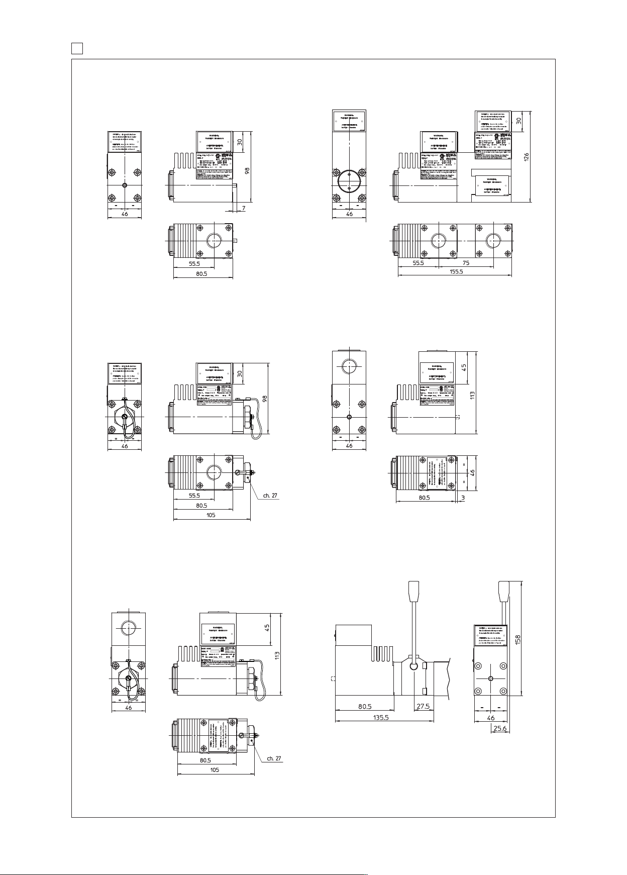
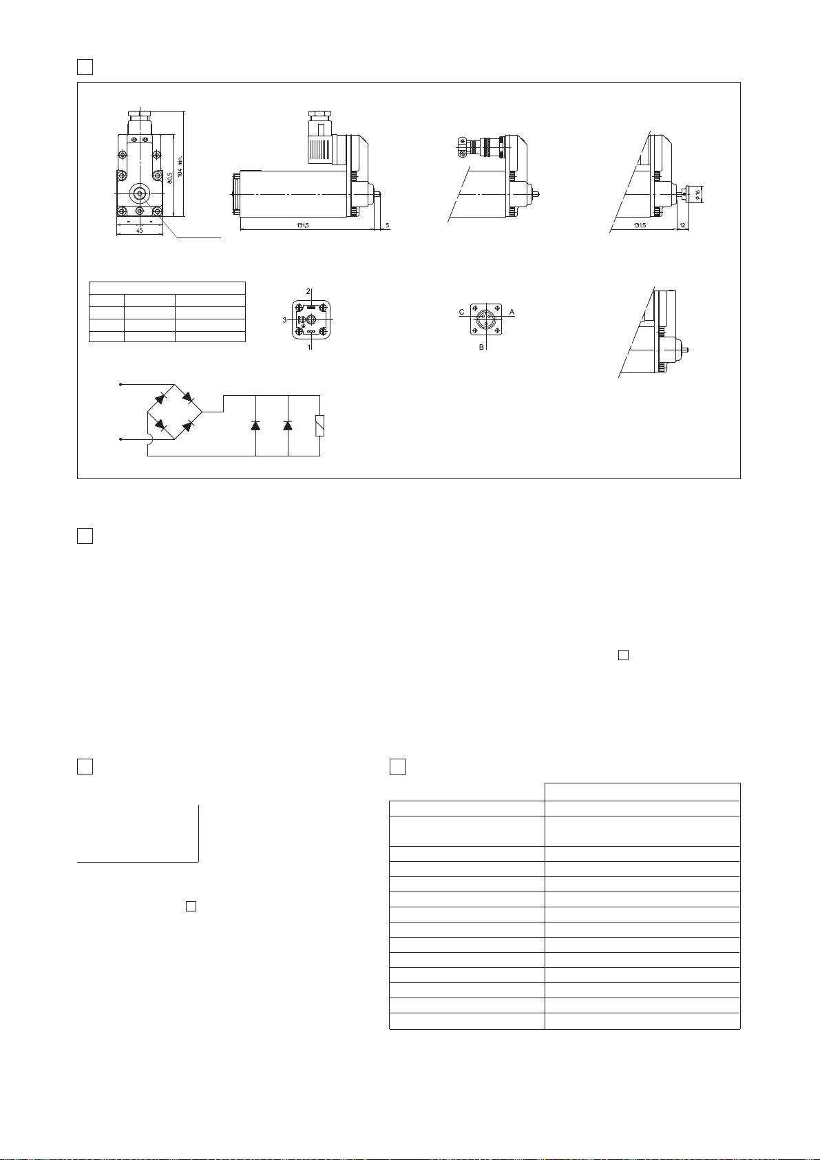
7 SOLENOIDS DIMENSIONS AND WIRING
2
AUL
O
ZAUL-A
O
ption /WP
O
only for OAUL
ZAUL-T
O
Mass: 3,71 kgMass: 1,92 kg
Option /O
Mass: 2,4 kg
Option /OWP
Mass: 2,1 kgMass: 2 kg
Option /MV
05/17
Page 6
Gas group
Temperature class
V max 27 V 19,5 V 19,11 V
Electrical characteristic
I max 130 mA 360 mA 360 mA
P max 0,9 W 1,64 W 1,72 W
Minimum supply current ≥ 65mA, for I.S. barriers see section 18 to 21
Surface temperature
(ambient temp. +60°C)
Ambient temperature -40 ÷ +60°C (1)
Nominal resistance at 20°C
Coil insulation
Protection degree
Duty factor
Electrical connector
www.atos.com
Intrinsically safe solenoid valves
on/off controls - ATEX certification
Table E130-17/E
E130
DHW-0611/WP/6
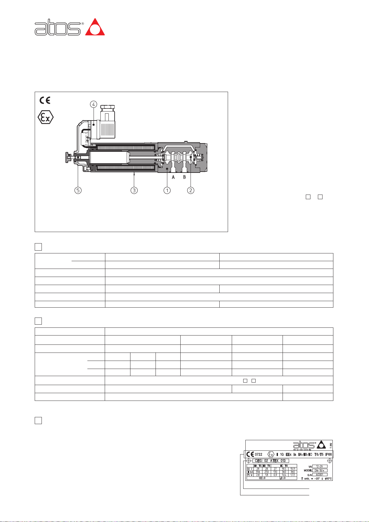
햲 valve body
햳 valve spool
햴 intrinsically safe solenoid
햵 electrical connector
햶 manual override
Ex = Equipment for explosive atmospheres
II = Group II for surface plants
I = Very high protection (equipment category)
G = For gas and vapours
ia = Intrinsically safe execution
IIC = Gas group - application in surface plants
T6 / T5 =
Temperature class of the solenoid surface
referred to +60°C ambient temperature
Zone 0
(1 and 2) =
Explosive atmosphere continuosly
present
3 CERTIFICATIONS
In the following is resumed the valves marking according to the Atex Group I and Group II certification
3.3 EXAMPLE OF NAMEPLATE MARKING
Notified body and certificate number
Marking according to Atex Directive
On/off valves equipped with intrinsecally
safe solenoids certified according to
ATEX 94/9/CE, protection mode:
- Ex II 1 G, Ex ia IIC T6, IIB T6 or IIA T5
(surface plants with gas or vapours environment, category 1, zone 0, 1 and 2).
- Ex I M2 Ex ia I (solenoids group I for surface, tunnels or mining plants).
"Intrinsically safe" protection is based on the
principle of limiting the energy of electric
circuits in environments with presence of
hazardous atmospheres. For this reason the
valves must be supplied through specific
“safety barriers” which limitate the max current to the solenoid. Atos provides galvanically insulated barriers for single and double
solenoid valves, see section
to . The
"intrinsically safe" circuit is virtually unable to
produce electrical surges or thermic effects
able to cause explosion in hazardous environments also in presence of specific
break-down situations.
2118
1 INTRINSICALLY SAFE SOLENOIDS: MAIN DATA
2 INTRINSICALLY SAFE SOLENOIDS: ELECTRICAL AND TEMPERATURE DATA
(1)
The Group II solenoids are Atex certified for minimum temperature -40°C. Select /BT in the valve code for the application with minimum temperature -40°C
3.1 GROUP II, Atex
Ex = Equipment for explosive atmospheres
I = Group I for mines and surface plants
M2 = High protection (equipment category)
d = Flame proof housing
I = Gas group (Methane)
3.2 GROUP I (mining), Atex
Group II
Group I (mining)
Solenoid code
OW-18/6
OWM-18/6
IP65
DIN 43650 2 pin+GND
OW-18/H
OWM-18/H
IP67
MIL-C-26482 3 pin
150 Ω
Class H
100%
≤ 85°C
I and IIB
T6
28 V
250 mA
1,8 W
I and IIA
T5
28 V
396 mA
2,8 W
I
-
12,2 V
2200 mA
6,82 W
≤ 100°C
150 °C
-20 ÷ +60°C
I and IIC
T6
Method of protection
Ex ia / Ex ib according to EN60079-0: 2006, EN60079-11:2007
Page 7
Assembly position the installation of DHW valves with the axis in vertical position is not recommended.
If this type of installation is absolutely necessary, please consult our technical office
Subplate surface finishing Roughness index flatness ratio 0,01/100 (ISO 1101)
Ambient temperature from -20°C to +60°C (standard, /WG and /PE seals) -40°C to +60°C for /BT option
Fluid Hydraulic oil as per DIN 51524 .... 535; for other fluids see section
Recommended viscosity 15 ÷ 100 mm2/s at 40°C (ISO VG 15 ÷ 100) max viscosity 400 mm2/s
Fluid contamination class ISO 18/15, achieved with in line filters at 10 μm value to β10≥75 (recommended)
Fluid temperature -20°C +60°C (standard, /WG and /PE seals) -40°C to +60°C for /BT option
4 MAIN CHARACTERISTICS OF INTRINSICALLY SAFE VALVES
A
DH = spool type - direct
DPH = spool type - piloted
Options:
/A = solenoid at side of port B
/WP = prolunged manual override
5 MODEL CODE OF SPOOL TYPE ON-OFF DIRECTIONAL SOLENOID VALVES
Valve configuration, DHW see section and DPHW see section
Spool type, DHW see section and DPHW see section
3H = spool type 3H for marine applications (1) Only for DHW-071
Synthetic fluids (2):
WG = water-glycol
PE = phosphate ester
Series number
DH 0–713H 6**
/*
Valve size (ISO 4401):
for DHW : 0 = size 06;
for DPHW : 1 = size 10 2 = size 16; 3 = size 25
Connector type - see section 17
/6 = DIN 43650 (standard)
/H = MIL-C-26482
//
W
W = intrinsecally safe solenoid, Atex certified
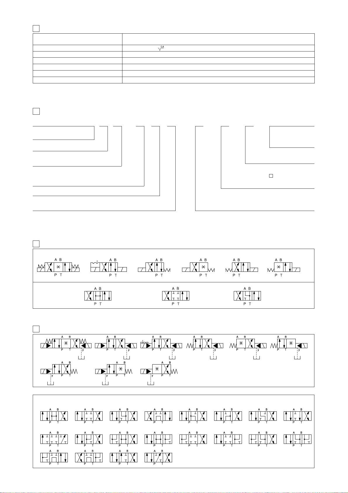
6 HYDRAULIC CONFIGURATIONS OF DHW VALVES
Where the symbol doesn't show the hydraulic connection (*), it depends by the central configuration of the spool
-071*
Configuration for DHW
Spools for DHW
-0750/2
-0751/2
-0630/2
-0631/2
061* -061*/A
0
0/2
1
1/2
3
3H
-0630/2/A
-0631/2/A
For all size
Only for DPHW-2, DPHW-3
0
0/2
2
2/2
94
1
1/2
8
49
3
90
16
4
09
17
5
91
58
19
6
93
7
39
-71*
-*63*/A
-*70
-*61*/A
-*75
-*67*/A
-*63 -*61 -*67
7 CONFIGURATION OF DPHW VALVES
Where the symbol doesn't show the hydraulic connection (*), it depends
on the central configuration of the spool;
Spools for DPHW valves
(1) Spool type 3H provides larger passages A-B to T in central position than spool type 3, see section 11.3
/*
omit for Group II
M = Group I (mining)
4.1 Corrosion protection characteristics
Valve screws: all screws made in stainless steel class A2
(2) Option /BT = low temperature -40°C also available on request (not for group I Atex -mining-)
Page 8
E130
10
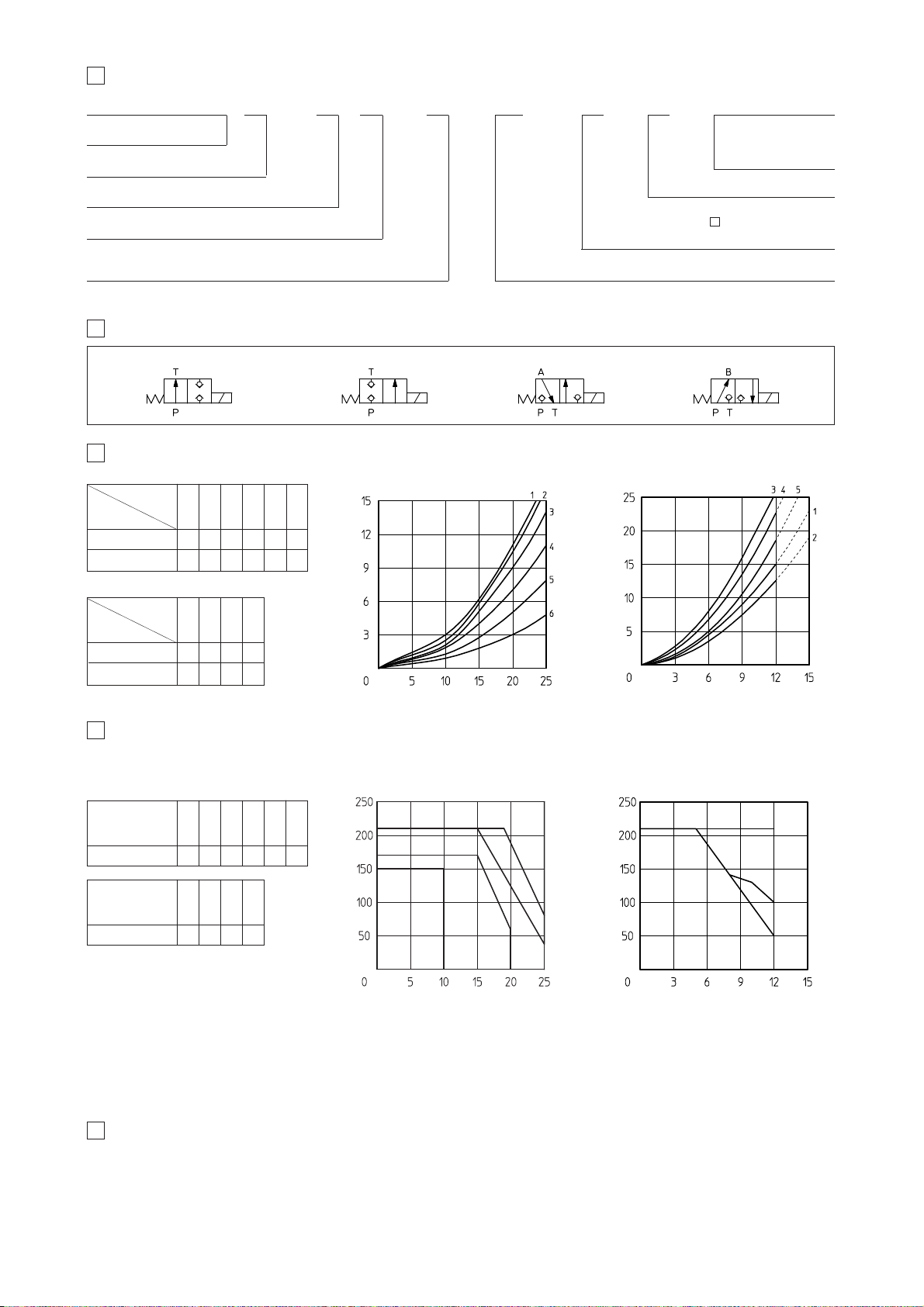
Q/Δp DIAGRAMS based on mineral oil ISO VG 46 at 50°C
DHW
DLOH*-WO
valve pressure drop [bar]
Flow rate [l/min]
Flow rate [l/min]
valve pressure drop [bar]
(1) For two-way valves pressure drop refers to P→T
11
OPERATING LIMITS based on mineral oil ISO VG 46 at 50°C
The diagrams refer to warm solenoids and power supply provided by the Atos barrier type Y-BXNE-412. For DHW valves the curves refer to
application with symmetrical flow through the valve (i.e. P → A and B → T). In case of asymmetric flow the operating limits must be reduced.
Flow rate [l/min]
Inlet pressure [bar]
C
A
B
DHW
Flow rate [l/min]
Inlet pressure [bar]
F
G
DLOH*-WO
E
9 HYDRAULIC CONFIGURATIONS OF DLOH VALVES
DLOH*-WO
DLOH-2A-WO DLOH-2C-WO DLOH-3A-WO DLOH-3C-WO
12 INTERNAL LEAKAGES
12.2 DLOH-*-WO internal leakages based on mineral oil ISO VG 46 at 50°C
less than 5 drops/min (0,36 cm
3
/min) at max pressure.
12.1 DHW internal leakages
18 cm
3
/min with P=100 bar - fluid viscosity = 43 cSt at 40 °C
30 cm
3
/min with P=140 bar - fluid viscosity = 22 cSt at 45 °C
11.1 Operating pressure:
Ports P, A, B = 350 bar Port T = 160 bar
11.2 Operating limits (only for DHW-0713H)
Max flow = 10 l/1’ - Max pressure = 150 bar
11.3 Flow capability in central position A-B
→ T (only for DHW-0713H)
Max flow = 25 l/1’ with Δp 10,5 bar
R
directional control valve,
poppet type size 06
Options:
/R = with check valve on port P
/WP = prolunged manual override
8 MODEL CODE OF POPPET TYPE LEAK FREE ON-OFF DIRECTIONAL SOLENOID VALVES
Synthetic fluids (1):
WG = water-glycol
PE = phosphate ester
Series number
DLOH A–6**
/*
Connector type - see section 17
/6 = DIN 43650 (standard)
/H = MIL-C-26482
//
2
2 = 2 way
3 = 3 way
A = open in rest position
C = closed in rest position
–
WO
/WO = intrinsically safe solenoid, Atex certified
/*
omit for Group II
M = Group I (mining)
DLOH*-WO
spool type
Flow direction
P→A / P→B (1)
A
→T / B→T
configuration
Flow direction
DHW
0
0/2
1/2
1
3
3H
P→A / P→B
A→T / B→T
4
6
5
2
5
1
3
2
3
4
3
5
2A
2C
3A
3C
1
-
2
-
4
5
3
4
Diagram
DHW type
DLOH type
00/21/2
1
3
3H
B
B
C
C
A
D
Diagram
2A 2C 3A
3C
G
G
F
E
D
(1) Option /BT = low temperature -40°C also available on request (not for group I Atex -mining)
Page 9
WO
Cover type:
LIDBH = with solenoid valve
and shuttle valve for pilot selection
LIDEW = with solenoid valve
for pilot selection
15 MODEL CODE OF COVERS FOR CARTRIDGE VALVES
Series number
LIDEW 1 *–6**
/*
Valve size (ISO 7368)
for LIDBH*: 1 = 16, 2 = 16, 3 = 16, 4 = 16, 5 = 50
for LIDEW* 1 = 16, 2 = 16, 3 = 16, 4 = 16, 5 = 50, 6 = 63, 8 = 80
Options:
/B = cartridge piloted via port “B” of solenoid pilot valve
/E =
external attachments X (G 1/4") and underneath port X supplied plugged (only for sizes 40 to 80)
Connector type - see section 17
/6 = DIN 43650 (standard)
/H = MIL-C-26482
/
-/
WO = Intrinsically safe solenoid, Atex certified
Note: for the code of the ISO cartridge to use with the above covers see tab. H003, section and tab. H030, section .
AGAM
AGAM = pressure relief valve,
subplate mounting, see tab. C066
ARAM = pressure relief valve,
threated connections, see tab. C045
13 MODEL CODE OF PRESSURE CONTROLS
Valve size
for AGAM:
10 = size 10 (ISO 6264);
20 = size 20 (ISO 6264);
32 = size 32 (ISO 6264);
20
Valve configuration
0 = venting with de-energized solenoid
1 = venting with energized solenoid
2 = without venting
2 0
Pressure range of first/second/third setting:
50 = 4 - 50 bar 210 = 7 - 210 bar
100 = 6 - 100 bar 350 = 8 - 350 bar
210 WO
Connector type - see section 17
/6 = DIN 43650 (standard)
/H = MIL-C-26482
/*
Series number
**–
/-//6
WO = Intrinsically safe solenoid, Atex certified
Synthetic fluids (1):
WG = water-glycol
PE = phosphate ester
Number of the different setting pressure values:
1 = one setting pressure
2 = two setting pressure
3 = three setting pressure
Synthetic fluids (1):
WG = water-glycol
PE = phosphate ester
14 HYDRAULIC CHARACTERISTICS
AGAM-**/10/***-WO
AGAM-**/20/***-WO
AGAM-**/11/***-WO
AGAM-**/21/***-WO
AGAM-**/22/***-WO
AGAM-**/32/***-WO
16 HYDRAULIC SYMBOLS
LIDBH1A-*
LIDEW1-* LIDEW2-* LIDEW4-* LIDEW5-* LIDEW6-*
LIDBH1C-*
LIDBH2A-*
LIDBH2C-*
Valve configuration, see section
16
1
for ARAM:
20 = G 3/4”;
32 = G 1 1/4”
/*
Omit for Group II
M = Group I (mining)
Valve model AGAM-10-WO AGAM-20-WO AGAM-32-WO
Max pressure
[bar] 350
Setting 50; 100; 210; 350
Pressure range
[bar] 4÷50; 6÷100; 7÷210; 8÷350
Max flow
[l/min] 200 400 600
/*
Omit for Group II
M = Group I (mining)
(1) Option /BT = low temperature -40°C also available on request (not for group I Atex -mining-)
(1) Option /BT = low temperature -40°C also available on request (not for group I Atex -mining-)
Option:
/WP = prolunged manual override
WP /
Page 10
18 INTRINSICALLY SAFE BARRIERS
The electric supply to these solenoids must be done through electronic devices situated out of potentially flammable environment (i.e. in safe
zone), which limit the electric current to the intrinsically safe solenoid. These electronic devices are normally called “intrinsically safe barriers”
approved and certified according to the Ex ia protection mode. To select the proper intrinsically safe barriers following data must be considered:
1) Vmax and Imax of the solenoid as specified in section must not be exceeded also in fault conditions;
2) the resistance of the solenoid is 150 Ω and the current supplied by the barrier, in normal operation condition, must be over the min. limit
(65 mA) to ensure the valve correct operation (over 70 mA for max performances).
The barriers type Y-BXNE 412 are galvanically isolated electronic devices, developed according to the European Norms EN60079-0/06, EN6007911/07 and certified ATEX 94/9/CE, protection mode Ex ia IIC.
These barriers ensure the optimized functioning of the Atos valves up to the max operating limits specified in section .
The barriers Y-BXNE-412 are double channel type, suitable to operate valves with double or single solenoid.
Two single solenoid valves can be connected to the barrier (one to each channel) but they cannot be contemporary operated.
11
E130
19 MODEL CODE OF I.S. BARRIER
Supply voltage
E = 110/230 VAC
2 = 24÷48 VDC
19.1 I.S. barrier for double solenoid valves
Y-BXNE 412 00 *
The above barrier can be used both for double or for single solenoid
valves.
With one barrier, two single solenoid valves can be operated but not
contemporary, see section .
18
17
SOLENOID DIMENSIONS AND WIRING
OW-18/6 (standard)Dimension [mm]
Option /H
DIN 43650 MIL-C-26482
Connector wiring
/6 /H Connections
1 A Coil
2 C Coil
3B GND
manual
override pin
note: the connectors are supplied with the valves
1 (A)
2 (C)
cover shape for mining version
Option /WP
20
TECHNICAL CHARACTERISTICS OF I.S. BARRIER
Y-BXNE 412
N° output channels 2
Power supply voltage 110÷230 V
AC ±10% (50/60 HZ)
21,6 ÷ 53 VDC
Power consumption < 3W
Output voltage Uo 19,5 V
Output current Io 341 mA
Output power Po 1,64 W
Galvanic insulation supply/output 2500 VAC / 50 Hz
Storage temperature -25 °C ÷ +70 °C
Working temperature -10 °C ÷ +60 °C
Housing material ABS case
Mounting on rail EN 50022
Electrical connections screw terminals
Method of protection Ex ia IIC
ATEX classification Ex II 1 G/D
Page 11
04/09
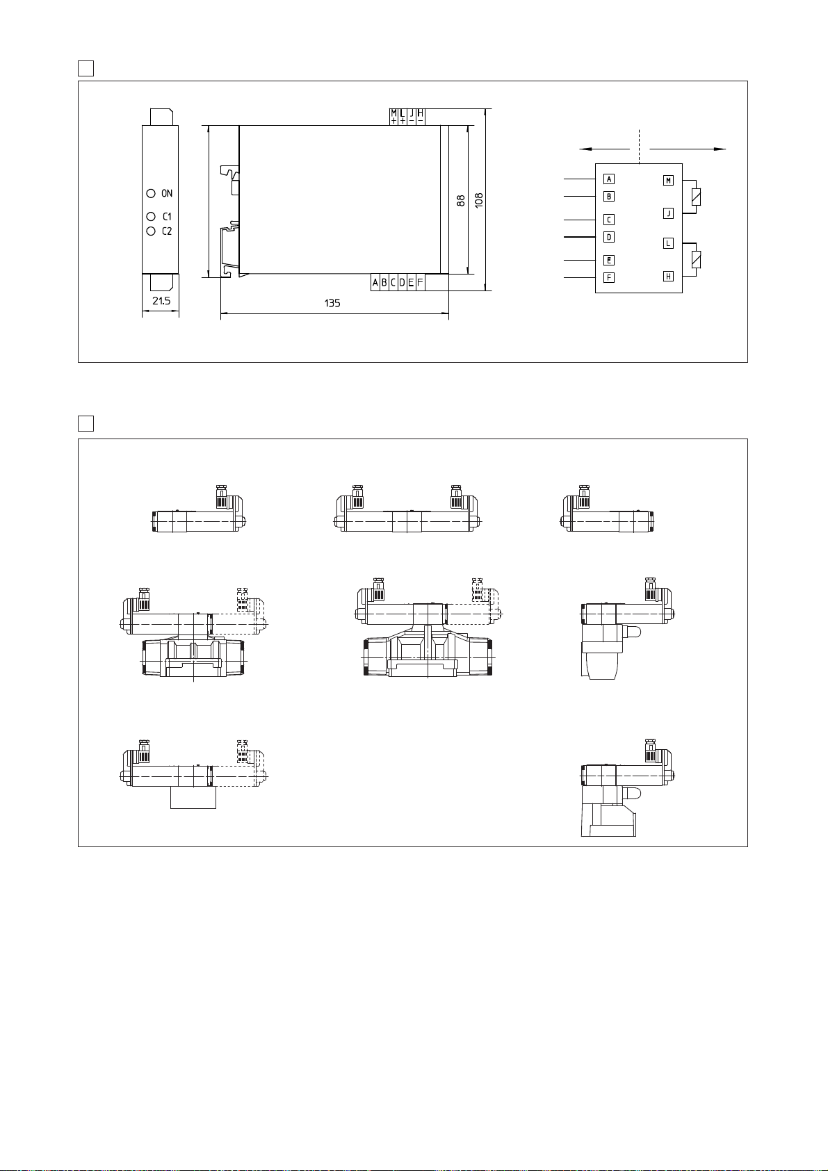
EXTERNAL PROFILE OF INTRINSICALLY SAFE VALVES [mm]
22
DHW-06
DPHW-16
DPHW-17
LIDEW1-*-WO
LIDEW2-*-WO
LIDEW4-*-WO
Safe zone Hazardous zone
INSTALLATION DIMENSIONS OF I.S. BARRIER [mm]
Power
supply
Input
command
Sol. B
Input
command
Sol. A
Sol. B
Sol. A
Y-BXNE 412
Y-BXNE 412
GND
GND
+24 V
DC
+24 VDC
+ VDC/~
- VDC/~
Power On
led
Sol. A
enabled led
Sol. B
enabled led
21
90
DHW-07
DPHW-26
DPHW-27
AGAM-10/1*-WO
AGAM-20/1*-WO
AGAM-32/1*-WO
DLOH-**/WO
ARAM-20/1*-WO
ARAM-32/1*-WO
Page 12
www.atos.com
Stainless steel valves for standard fluids
explosion-proof solenoid valves and pressure relief valves
Table E136-0/E
E136
1 STAINLESS STEEL VALVES: MAIN DATA
Code
(1)
Description ISO size
Voltages
DC AC
ATEX T class
(1)
Standard Option /7
Input Power
W
Max flow
l/min
Δp
(at max flow)
bar
Max pressure
bar
(2)
DLOHXS6-AO
DLOHXS4-AO
3 way, poppet type,
direct solenoid valves
06
(ISO 4401)
06
(ISO 4401)
no
no
no
no
no
06
(ISO 4401)
25
(ISO 7368)
T6
T4
T6
T4
T6
–
–
–
–
–
–
–
–
–
–
–
–
12
24
48
110
198
220
12/50/60
24/50/60
110/50
120/60
220/50
220/60
8
25
8
25
8
10
12
25
30
220
220
40
400
30
35
6
350
DHAXS6
DHAXS4
4 way, spool type
direct solenoid valves
06
(ISO 4401)
T6
T4
T4
T3
T4
T3
T4
–
–
–
T4
T3
8
25
60
70
see diagram
at section
8
350
250
315
315
315
350
350
3 way, poppet type,
direct solenoid valves
3 way, poppet type,
piloted solenoid valve
3 way, poppet type,
hydraulic operated valve
relief valve
direct screw-in
relief valve
direct modular
relief valve
DIN cartridge
DLOKXS6-AO
DLOKXS4-AO
DLOPXS6-AO
DLPXS
SP-CART-MXS-3
SP-CART-MXS-6
SP-CART AREXS-20
HMPXS-*
LIMMXS-2/*
(3)
Notes:
1) X6 and X4 versions differ only for the coil power (see Input Power) - The certified temperature class T6, T4, T3 is related to the max ambient temperature, from which results
the max solenoid surface temperature allowed in the application (see section
3
). The reference ambient temperature is -40÷+40°C (standard, see the sixth column in the
above table), for higher ambient temperature (-40÷+70 °C) the temperature class has to be degraded (option /7).
2) Max pressure on T port = 110 bar
3) Optional electrohydraulic venting available on request.
4) Valves are provided by NBR seals, which allow min ambient temperature down to -40 °C (max oil viscosity = 380 cSt). The min ambient temperature fr valves with PE option
(FPM seals) is -20°C.
Valve type
solenoid housing
DLOHXS
DLOKXS
AISI 630
AISI 630
–
–
–
–
valve body
AISI 316L
AISI 630
AISI 630
AISI 316L
AISI 316L
AISI 316L
internal parts
+
seals
NBR (
buna)
FPM (
viton)
DHAXS
AISI 630 AISI 316L NBR (
buna)
FPM (
viton)
NBR (
buna)
FPM (
viton)
NBR (
buna)
FPM (
viton)
NBR (
buna)
FPM (
viton)
NBR (
buna)
FPM (
viton)
NBR (
buna)
FPM (
viton)
DLOPXS
DLPXS
SP-CART-*XS
HMPXS
LIMMXS
std /PE
2 MATERIALS SPECIFICATION
New line of directional solenoid valves and
pressure relief valves with stainless steel
external parts for corrosive environments.
Stainless steel solenoids , ex-proof Atex,
for hazardous areas - see section
3
.
Features:
•These valves are made by selected
inoxidizable materials for external
parts to withstand extreme and
corrosive environmental conditions.
Internal components are in carbon steel.
•
Directional valves are available in two basic
versions: poppet type, 3-way leak free
(suitable for accumulator systems) or spool
type, 4-way on-off valves.
•Explosion proof solenoids with ATEX
94/9/CE certification, protection mode Ex II
2G, Ex d IIC T6/T4/T3
•Standard manual override pin protected
by a sealed stainless steel cap.
•Cable connection M20x1,5.
•Stainless steel cable glands available
•ISO standard subplate mounting.
Options:
•Handwheel manual override (option /V)
•Manual reset (option /R) for safety
applications
•Horizontal cable entrance.
Common Applications:
Offshore, Marine.
B
P
A
B
A
A
B
DLOKXS4-3A/M-AO/R
DHAXS4-0711/M
DLOHXS6-3A/M-AO/V
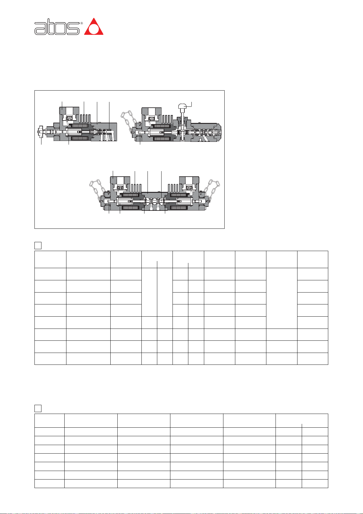
햲 Ex-proof solenoid
햳 Valve body
햴 Solenoid plunger
햵 Spool / poppet
햶 Spring
햷 Manual override pin
햸 Cable entrance
햹 Handwheel manual override
햺 Manual reset
–
–
–
–
–
–
–
–
–
–
–
–
–
–
–
2,5
40 (60 PED)
120 (150 PED)
350
350
400
Carbon steel
Carbon steel
Carbon steel
Carbon steel
Carbon steel
Carbon steel
Carbon steel
spring
AISI 302
AISI 302
AISI 302
AISI 302
AISI 302
AISI 302
AISI 302
Page 13
PA1/2 M / V
Spool type - direct
Stainless steel execution for external parts
Solenoid threated connection:
M = M20x1,5 UNI-4535 (6H/6g)
4 SPOOL TYPE DIRECTIONAL SOLENOID VALVES: MODEL CODE
Size:
0 = 06
Valve configuration, see section 4.1
61, 63, 71, 75
(configurations 63 and 75 are available only with spool type 1/2)
Spool type, see section 4.2
Synthetic fluids:
WG = water-glycol
PE = phosphate ester
Series number
DHA 4XS 0 63 24DC **
/*
Temperature class
4 = T4
6 = T6
Voltage code - see section
3
–/-
Optional cable gland:
PA = with threaded cable gland, see section
0
1
1/2
367
4.2 Spools - for intermediate passages, see tab. E001.
-071*
-071*/V-061*/A-0631/2/A
-0751/2
-06*/V
-0631/2 -061*
4.1 Hydraulic configuration
Where the symbol doesn't show the hydraulic connection (*), it depends on the central configuration of the spool; see section 4.2.
Options:
A = solenoid at side of port B
V = with handweel manual override
7 = for ambient temperature up to 70°C
O = horizontal cable entrance
3 EXPLOSION PROOF SOLENOIDS: MAIN DATA
DHAXS4
DLOHXS4
DLOKXS4
VALVE TYPE
Solenoid code Group II, ATEX OAX/WP OAKX/WP
Power consumption 8W 25W
Coil insulation Class H
Protection degree IP 67 According to IEC 144 when correctly coupled with the relevant cable gland SP-PAX19*, see section
16
Duty factor
Mechanical construction
Cable entrance and
electrical wiring
Explosion proof safety case classified Ex d, according to EN 60079-0: 2006, EN 6079-1: 2007
Metod of protection Ex d
Temperature class (surface temp.)
T6 (≤ 85°C) T4 (≤ 135°C) option /7 T4 (≤ 135°C) T3 (≤ 200°C) option /7
Ambient temperature
(according Atex cerification)
Certification
Ex = explosion proof according to EN 60079-0, EN 60079-1
d = flame proof execution
IIC = gas group - application in surface plants
Zone 1 (and 2) = explosive atmosphere desultorily present
T6 (T4, T3) = temperature class of the solenoid surface is dependent to the ambient temperature
-40 ÷ +45 °C -40 ÷ +70 °C -40 ÷ +40 °C -40 ÷ +70 °C
Internal terminal board for cable connection threaded connection M20x1,5 for cable entrance, vertical (standard) or Horizontal (option /O)
See section
16 for cable grand
Voltage 12DC, 24DC, 48DC, 110DC, 220DC
code 12AC, 24AC, 110AC, 230AC (1)
VDC
VAC 50/60 Hz
1 = Coil
2 =GND
3 = Coil
Solenoid wiring
(1) For alternating current supply a rectifier
bridge is integrated in the solenoid
16
DLOHXS6
DLOKXS6
DLOPXS6
100%
±10%
±10%
Page 14
E136
MPA AO / V
DLOH - DLOK = poppet type - direct
DLOP = poppet type - piloted
DLP = as DLOPX but without pilot valve
Stainless steel execution for external parts
Solenoid threated connection:
M = M20x1,5 UNI-4535 (6H/6g)
5 POPPET TYPE LEAK FREE DIRECTIONAL SOLENOID VALVES: MODEL CODE
3 = three way
Valve configuration, see section 5.1
A = A to T in rest position
C = P to A in rest position
Synthetic fluids:
WG = water-glycol
PE = phosphate ester
Series number
DLOH 6XS 3 A 24DC **
/*
Temperature class
4 = T4 (for DLOHXS and DLOKXS)
6 = T6 (for all models)
Voltage code - see section
3
–/--
AO = explosion proof solenoid
Optional cable gland:
PA = with threaded cable gland, see section
5.1 Hydraulic configuration
DLOHXS*-3A/M-AO/V DLOHXS*-3C/M-AO
DLOPXS6-3A/M-AO
DLOKXS*-3A/M-AO/R DLOKXS*-3C/M-AO
DLOPXS6-3C/M-AO DLPXS-3A DLPXS-3C
6.5 hydraulic configuration
SP-CART-*XS
LIMMXS-2/*
SC LI-2531*
Options: ( not for DLPX )
R = with solenoid manual reset
V = with handweel manual override
7 = for ambient temperature up to 70°C
O = Horizontal cable entrance
Only for DLOPXS
D = internal drain
E = external pilot pressure
P
T
X Y
A
P
T
X Y
A
P
T
P
T
A
A
P
T
A
P
T
A
P
T
X
A
P
T
X
A
Screw-in relief
cartridge
6 PRESSURE CONTROL VALVES: MODEL CODE
SP-CART 350MXS /
6.1 Screw-in type
Modular pressure relief
valve ISO 4401 size 06
Pressure range
for HMP:
50 =50 bar
100 = 100 bar
210 = 210 bar
350 = 350 bar
Stainless steel execution
for external parts
HMP 011XS 350
Configuration, see section 6.5
011, 013, 014
/-
Cover according to
ISO 7368
Stainless steel execution
for external parts
LIMM 2XS 350
Size
2 = 25
/
6.3 Control cover
-
6.2 Modular type
Cartridge according to
ISO 7368
Area ratio 1÷1
SC LI 25 31 2
Size 25
-
6.4 Standard cartridge valve to be coupled with LIMMX cover
*
/
*
/
**
/
*
Stainless steel execution for
external parts and size
MXS-3 =G1/2
MXS-6 =M33x1,5
AREXS-20 =M35x1,5
Series number
Only for PED
P = factory preset regulation
Options
PED = reduced leakages and
certified according to 97/23/CE
**
/
*
Series number
**
/
*
Series number
**
/
*
Series number
Spring cracking pressure
1 = 0,3 bar 2 = 1,2 bar
3 = 3 bar 6= 6 bar
Pressure range
50 = 6 ÷ 50 bar 100 = 8 ÷ 100 bar
210 = 10 ÷ 210 bar 350 = 15 ÷ 350 bar
P
T
P1
A1 T1
P
A T
B1
B
A
B
Y
F
X
P1
A1 T1
B1
P
A T
B
P1
A1 T1
P
A T
B1
B
HMPXS-013/* HMPXS-014/*HMPXS-011/*
16
Pressure range
50 = 50 bar (not for AREXS-20 PED)
100 = 100 bar
210 = 210 bar
315 = 315 bar (only for AREXS-20)
350 = 350 bar (not for AREXS-20)
400 = 400 bar (only for AREXS-20)
Synthetic fluids:
WG = water glycol
PE = phosphate ester
Synthetic fluids:
WG = water glycol
PE = phosphate ester
Synthetic fluids:
WG = water glycol
PE = phosphate ester
Synthetic fluids:
WG = water glycol
PE = phosphate ester
Page 15
7
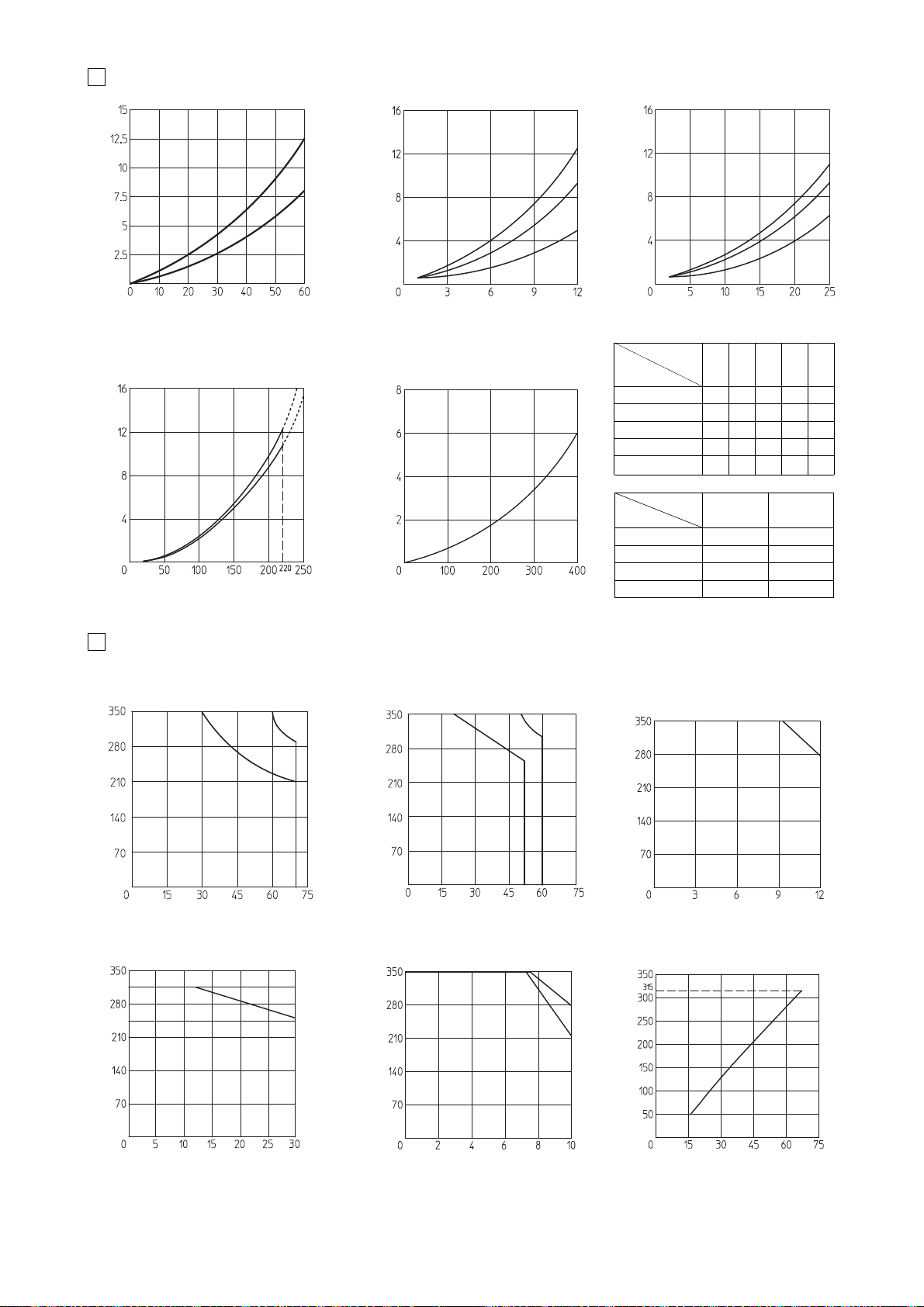
Q/Δp DIAGRAMS (based on mineral oil ISO VG 46 at 50°C)
8
OPERATING LIMITS OF ON/OFF DIRECTIONAL CONTROLS (based on mineral oil ISO VG 46 at 50°C)
The diagram have been obtained with warm solenoids and power supply at lowest value (Vnom-10%). For DHAXS valves the curves
refer to application with symmetrical flow through the valve (i.e. P → A and B → T). In case of asymmetric flow the operating limits
must be reduced.
Flow rate [l/min]
Flow rate [l/min]
valve pressure drop [bar]
valve pressure drop [bar]
A
C
B
F
E
D
Flow rate [l/min]
Inlet pressure [bar]
A-T
P-A
SCLI-2531*
Differential pressure A→B [bar]
P → AA→ T
(P → B) (B →T)
DLOHXS-3A CB
DLOHXS-3C BA
DLOKXS-3A FE
DLOKXS-3C ED
Flow direction
Valve type
DLOHXS
DLOKXS
DLOPXS
0 BBBBA
1, 1/2 AAAA
3 AABB
6 AABA
7 AAAB
DHAXS
DHAXS
valve pressure drop [bar]
Flow rate [l/min]
A
B
Flow direction
Spool type
P→AP→BA→TB→TP→T
Flow rate [l/min]
Flow rate [l/min]
Flow rate [l/min]
Piloting pressure [bar]
minimum
piloting pressure
3A
3C
3A
3C
DLOHXS4
DLOHXS6
DLOPXS and DLPXS
Flow rate [l/min]
Inlet pressure [bar]
Inlet pressure [bar]
Inlet pressure [bar]
Inlet pressure [bar]
M
S
DHAXS4
M = Spools 0, 1 S = Spools 1/2, 3, 6, 7
8.2 Piloting pressure (DLOPXS and DLPXS)
- max piloting pressure = 315 bar
- min piloting pressure = see diagram
Flow rate [l/min]
DLOKXS4-3A
DLOKXS4-
3C
DLOKXS*
Inlet pressure [bar]
Flow rate [l/min]
Inlet pressure [bar]
M
S
DHAXS6
M = Spools 0, 1 S = Spools 1/2, 3, 6, 7
internal leakage of DLOHXS, DLOKXS,
DLOPXS and DLPXS: less than 5 drops/min
(0,36 cm
3
/min) at max pressure.
DLOKXS6-3A, 3C
8.1 Internal leakages
Page 16
Min. regulated pressure
Regulated pressure [bar]
Flow [l/min]
Regulated pressure [bar]
Flow [l/min]
Regulated pressure [bar]
Flow [l/min]
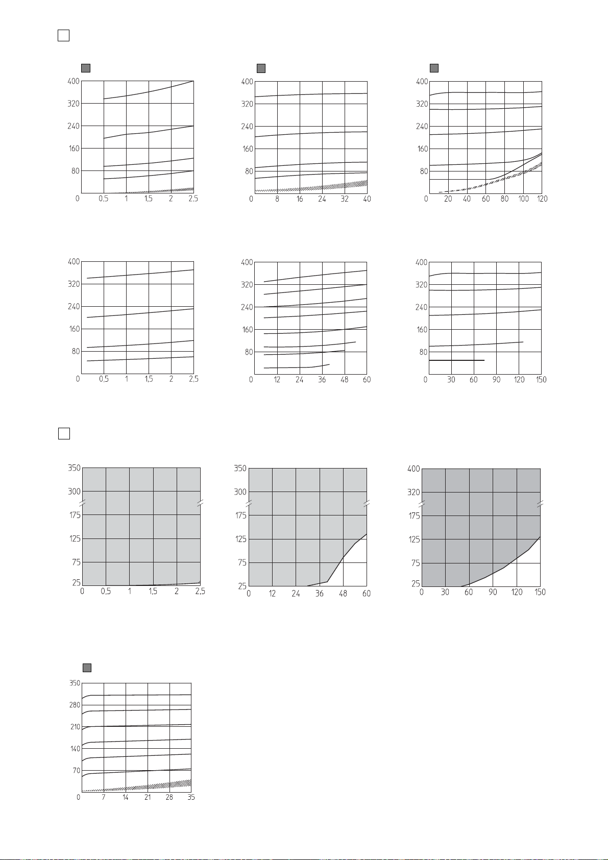
PERMITTED WORKING RANGES of screw-in cartridge valves with PED option (shared area)
SP-CART MXS-3 **/PED
Regulated pressure [bar]
Flow [l/min]
Regulated pressure [bar]
Flow [l/min]
SP-CART MXS-6 **/PED
SP-CART MXS-3 **/PED
Regulated pressure [bar]
Flow [l/min]
Regulated pressure [bar]
Flow [l/min]
SP-CART MXS-6 **/PED
Regulated pressure [bar]
Flow [l/min]
SP-CART AREXS-20 **/PED
Regulated pressure [bar]
Flow [l/min]
SP-CART AREXS-20 **/PED
HMPXS-*
Min. regulated pressure
Flow rate [l/min]
Regulated pressure at port P [bar]
9
REGULATED PRESSURE VERSUS FLOW DIAGRAM of screw-in cartridge valves (based on mineral oil ISO VG 46 at 50°C)
10
10.1 Regulated pressure for modular valves
E136
SP-CART MXS-3
SP-CART MXS-6
SP-CART AREXS-20
Min. regulated pressure
Min. regulated pressure
Page 17
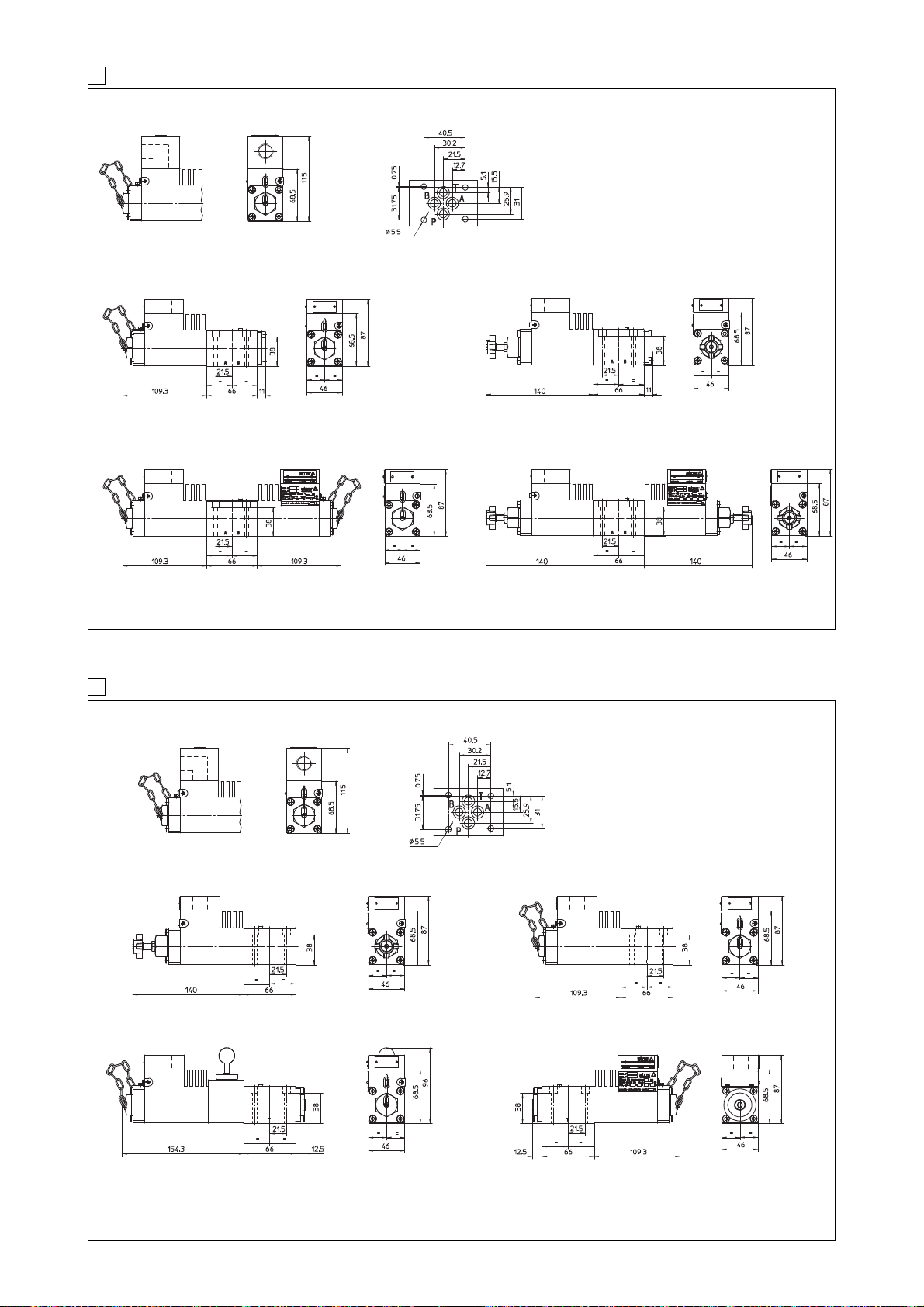
11 INSTALLATION DIMENSIONS OF DHAXS [mm]
DHAXS4-06* DHAXS4-06*/V
DHAXS4-07* DHAXS4-07*/V
ISO 4401: 2005
Mounting surface:
4401-03-02-0-05
Fastening bolts:
4 socket head screws M5x50-A4-70
Tightening torque = 5,5 Nm
Seals: 4 OR 108
Ports P,A,B,T: Ø = 7.5 mm (max).
P = PRESSURE PORT
A, B = USE PORT
T = TANK PORT
Mass: 2,9 kg Mass: 3 kg
Mass: 4,6 kg Mass: 4,8 kg
12 INSTALLATION DIMENSIONS OF DLOHXS AND DLOKXS [mm]
DLOHXS6-3A/M-AO/V
DLOKXS4-3A/M-AO/R
DLOHXS4-3C/M-AO
DLOKXS4-3C/M-AO
ISO 4401: 2005
Mounting surface:
4401-03-02-0-05
Fastening bolts:
4 socket head screws M5x50-A4-70
Tightening torque = 5,5 Nm
Seals: 4 OR 108
Ports P,A,B,T: Ø = 7.5 mm (max).
P = PRESSURE PORT
A, B = USE PORT
T = TANK PORT
Mass: 3 kg
Mass: 3,8 kg
Mass: 2,9 kg
Mass: 2,9 kg
hortizontal cable entrance oprtion /O
hortizontal cable entrance oprtion /O
Page 18
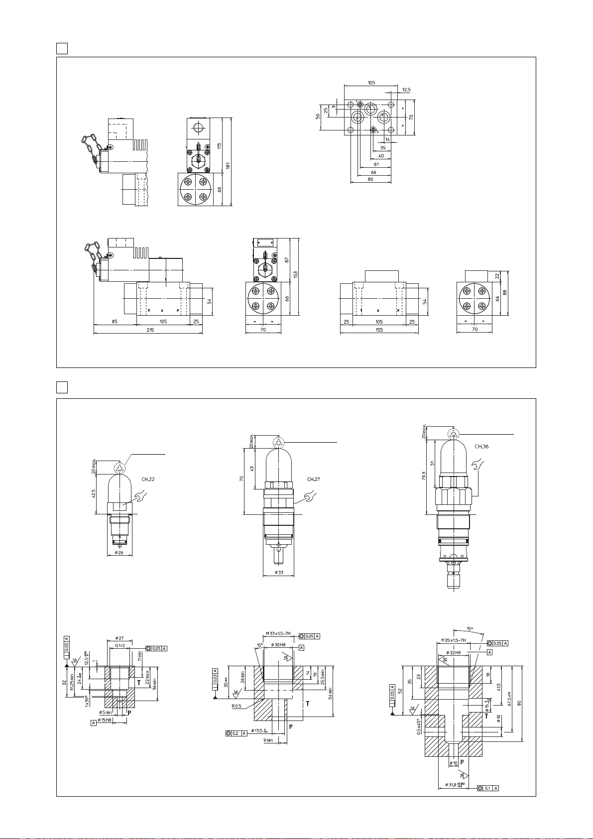
13 INSTALLATION DIMENSIONS OF DLOPXS AND DLPXS [mm]
14 INSTALLATION DIMENSIONS OF SCREW IN PRESSURE RELIEF VALVES [mm]
DLOPXS6-3A/M-AO
DLOPXS6-3C/M-AO
DLPXS-3A
DLPXS-3C
SP-CART MXS-6/*
Mass: 7 kg Mass: 4,5 kg
Recess dimensions
for SP-CART MXS-6
Mounting surface of DLOPXS and DLPXS is not ISO standard
Fastening bolts:
4 socket head screws M10x70-A4-70
Tightening torque = 40 Nm
Seals: 3 OR 3081; 2 OR 108
Ports P,A,T: Ø = 16 mm (max)
Ports X, Y: Ø = 7 mm (max)
hortizontal cable entrance oprtion /O
SP-CART MXS-3/*
Recess dimensions
for SP-CART MXS-3
SP-CART AREXS-20
Recess dimensions for
SP-CART AREXS-20
lead saled
regulation
(option /PED)
lead saled regulation
(option /PED)
E136
lead saled regulation
(option /PED)
60 Nm
55 Nm
140 Nm
Page 19
16 CABLE GLAND
Following codes have to be specified for spare cable glands:
SP-PAXS19/M = with threated connection M20x1,5 UNI-4535 (6H/6g).
This cable gland must be blocked with loctite or similar or
with a lock nut.
The valves must be connected to the power supply using the
terminal board inside the solenoid.
STAINLESS STEEL CABLE GLAND SP-PAXS19/* (PG9 - IP67)
Stainless steel cable glands - available on request - are certified ATEX
according to EN60079-0 and EN60079-1.
The cable must be suitable for the working temperature as
specified in the “safety instructions” delivered with the first
supply of the products.
Additional equipotential grounding can be also performed by the
user on the external facility provided on the solenoid case.
Minimum section of external ground wire = 4 mm
2
.
Minimum section of internal ground wire = the same of supply wire.
In order to reach the terminal board inside the solenoid, the top
plate of the solenoid must be removed.
Solenoids are provided with threated connection for cable
entrance:
M20x1,5 (UNI-4535)
10/07
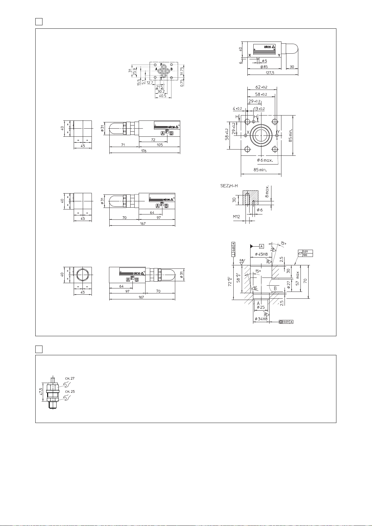
HMPXS-011/*
LIMMXS-2/*
Mass: 1,4 kg
Recess dimensions
for SC LI-25
Cover interface
dimensions for LIMMXS-2
Mass: 2,2 kg
15 INSTALLATION DIMENSIONS OF MODULAR AND CARTRIDGE VALVES
ISO 4401: 2005
Mounting surface:
4401-03-02-0-05
Fastening bolts: M5x**-A4-70
Tightening torque = 5,5 Nm
Seals: 4 OR 108
Ports P,A,B,T: Ø = 7.5 mm (max)
HMPX-013/*
HMPX-014/*
Mass: 1,2 kg
Mass: 1,2 kg
Page 20
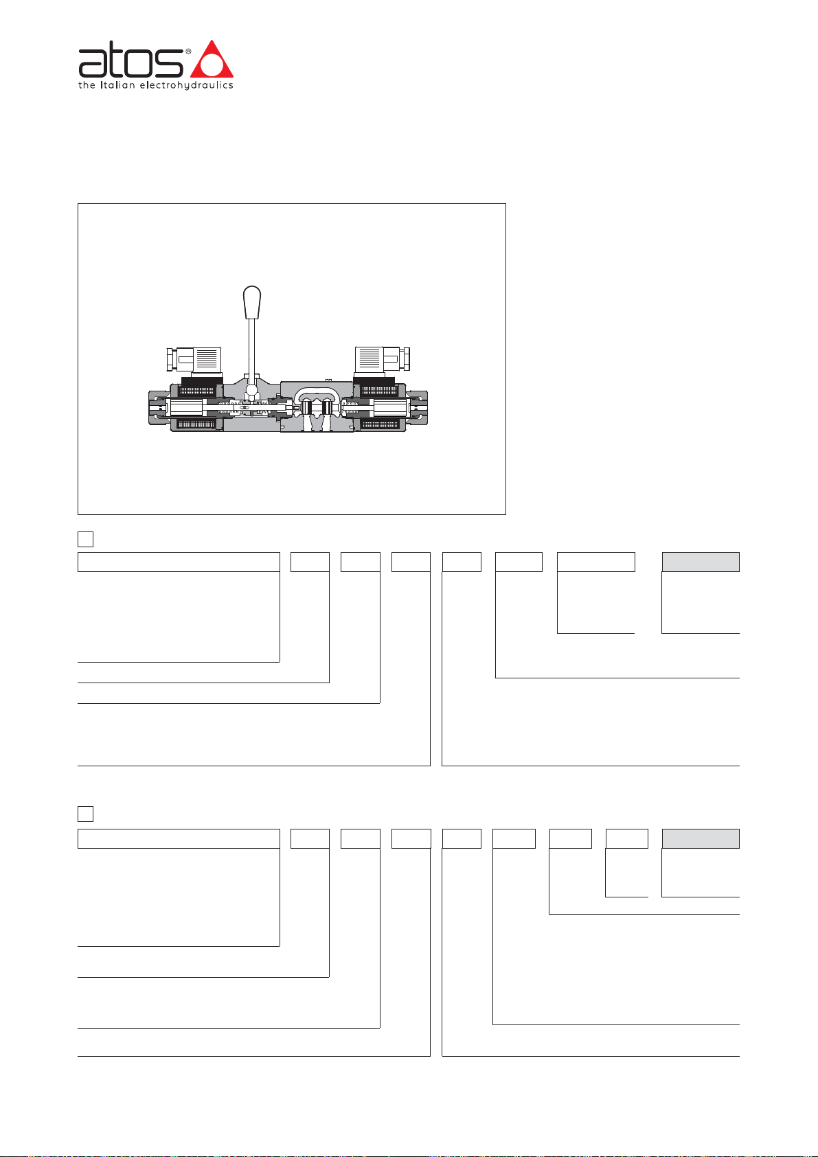
www.atos.com
Auxiliary hand levers for solenoid valves
direct operated on-off and proportional, ISO 4401 size 06
Table E138-7/E
Auxiliary hand levers for direct operated on-off solenoid valves size 06, type
DHI, DHE, DHA and proportional valves size 06, type DHZO, DHZE, DHZA
and QVHZO.
This option allows to operate the valves
in absence of electrical power supply,
i.e. during commissioning, maintenance or in case of emergency.
It is available with two different configurations depending to the installation
requirements:
MV = lever positioned vertically (per-
pendicular to the valve axis)
MO = lever positioned horizontally
(parallel to the valve axis)
When the valve is electrically operated
the hand lever remains stopped in its
rest position
The hand lever execution does not
affect the performances of the original
valves.
Directional control valves size 06
DHI-0=
for AC and DC supply, with CUR
US
certified solenoids - see table E010
DHE-0 = for AC and DC supply, high
performances, with
CURUS certi-
fied solenoids - see table E015
DHA-0 = ex-proof
(1)
Valve configuration:
61 - 63 - 71
Available spools:
0 - 0/2 - 1 - 1P - 1/2 - 1/2P - 3 - 3P - 4 - 7
1
MODEL CODE FOR ON-OFF DIRECTIONAL VALVES (for the details, see indicated tech. table)
E138
Options, hand lever configuration:
MO = horizontal hand lever (not for DHA)
MV = vertical hand lever
AMO = horizontal hand lever installed at the side of port B (not for DHA)
AMV = vertical hand lever installed at the side of port B
DHE-0711/MV
AB
Series number
-
DHE - 0
63 1/2 MV X
24 DC ** /*
Seals material:
- =
NBR
PE = FKM
BT = HNBR
2
MODEL CODE FOR PROPORTIONAL DIRECTIONAL VALVES AND FLOW CONTROL VALVES (for the details, see indicated tech.table)
Options:
MO = horizontal hand lever (not for DHA, DHZA)
MV = vertical hand lever
BMO = horizontal hand lever installed at the side of
port A (not for DHZA, QVHZO)
BMV =
vertical hand lever installed at the side of port A
(not for QVHZO)
O =
Horizontal cable entrance (only for DHZA)
Y = External drain (only for DHZA, DHZO)
(1) For DHZA model code see table F600 (Multicertification) or E125 (UL)
(2)
Valves with position transducer (-T) and/or integrated electronics (only double solenoid valves -TE/-AE) available on request
/
Voltage code:
see relevant tech. table
Only for DHI and DHE:
00 =
solenoids without coils, for DHI valve
00-AC =
AC solenoids without coils, for DHE valve
00-DC =
DC solenoids without coils, for DHE valve
X = without connector
A = without position transducer
(2)
Series
number
DHZO
A
0 71 S5
MV ** /*
Seals material:
- =
NBR
PE = FKM
BT = HNBR
/
Spool size (for DHZ*): S3 - S5 - D3 - D5 - L3 - L5
Max regulated flow (for QVHZO): 3-12-18-36-45 l/min
--
Valve size
0 = ISO 4401 size 06 (for DHZ*)
06 = ISO 4401 size 06 (for QVHZO)
Valve configuration (only DHZ*): 51, 53, 71, 73
Directional proportional valves size 06
DHZO =
see table F160
DHZE =
see table F150
DHZA = ex-proof
(1)
Flow control valves size 06
QVHZO = see tab F410
Coil option: see relevant tech. table
/*
-
(1) For DHA model code see table E120 (Multicertification) or E125 (UL)
Page 21
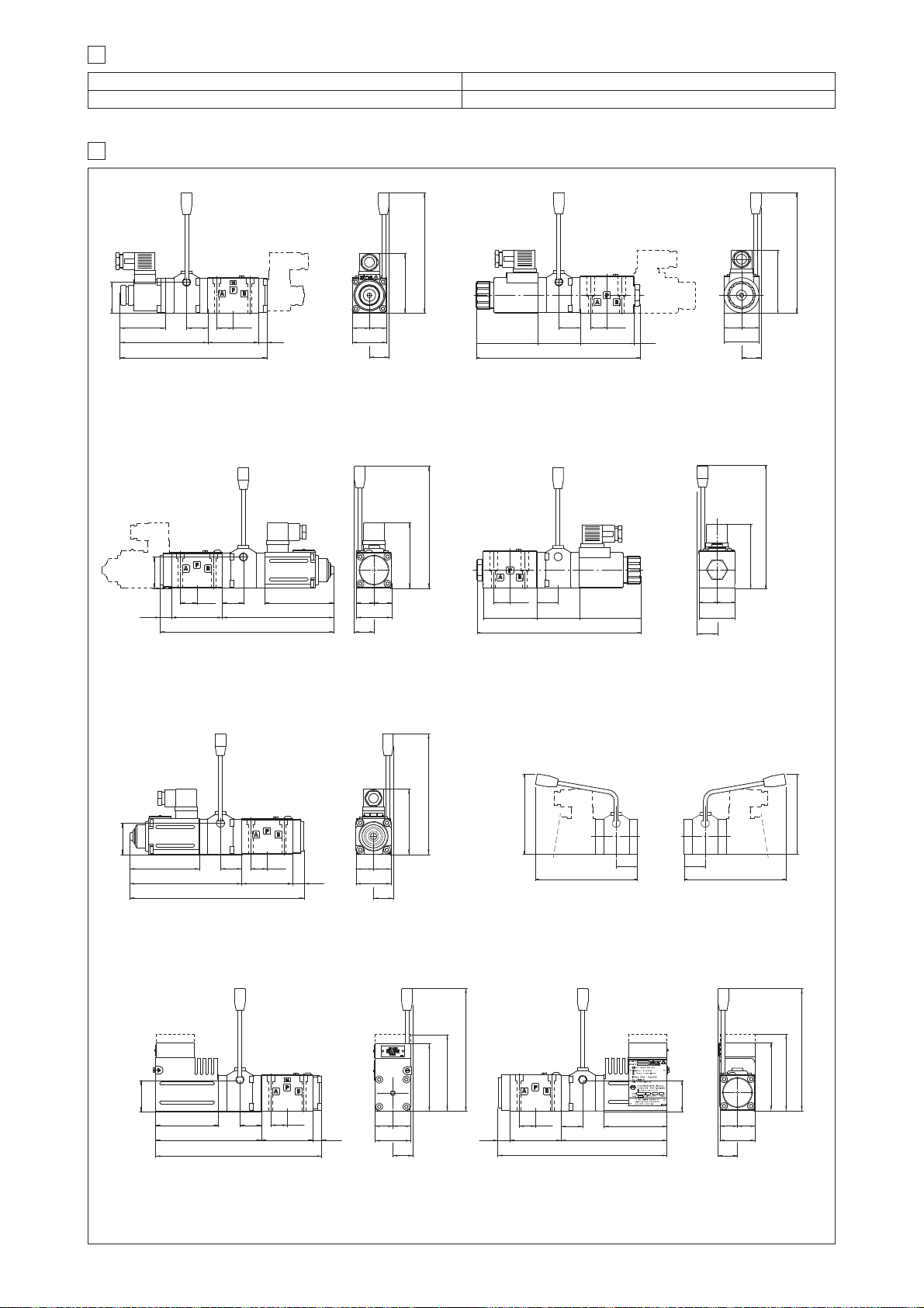
4 INSTALLATION DIMENSIONS [mm]
02/15
Mass: 2,8 kg (single solenoid)
Mass: 3,5 kg (double solenoid)
DHZO-A-05*/MV
DHZO-A-07*/MV (dotted line)
Mass: 3,4 kg
DHA/*-06*/MV
DHA/UL-*-06*/MV
DHZA/*-06*/MV
DHZA/UL-*-06*/MV
(dotted line)
(dotted line)
Mass: 2,4 kg (single solenoid)
Mass: 2,7 kg (double solenoid)
DHI-06*/MV
DHI-07*/MV (dotted line)
114
191
66
40.5
59 27.5 21.5
11
45
=
=
25.6
78
158
66
90.5
145.5
226.5
27.521.5
15
46
25.6
=
=
40.5
85
158
80.5
135.5
216.5
66
27.5 21.5
15
46
25.6
=
=
40.5
87
98
158
46
25.6
=
=
87
98
158
40.5
80.5
135.5
216.5
66
27.521.5
15
Mass: 2,7 kg (single solenoid)
Mass: 3,0 kg (double solenoid)
DHE-06*/MV
DHE-07*/MV (dotted line)
45
=
=
25.6
82
158
73
69
7.7
27.5
21.5
55
204.7
Mass: 2,7 kg (single solenoid)
Mass: 3,0 kg (double solenoid)
DHZE-05*/MV
DHZE-07*/MV (dotted line)
45
=
=
25.6
82
158
73
69
27.521.5
55
204.7
Mass: 3,2 kg
QVHZO-A-06*/MV
66
90.5
145.5
226.5
27.5 21.5
15
40.5
46
25.6
=
=
85
158
105
105
27.5 27.5
(max 120)
105
(max 120)
105
Horizontal hand lever device
/MO, /AMO
3 LEVER CHARACTERISTICS
Total angle stroke [°deg] ± 28°
Working angle stroke [°deg] ± 15°
Lever actuating force [N] 1 ÷ 8
Lever device weight [g] 880
Page 22
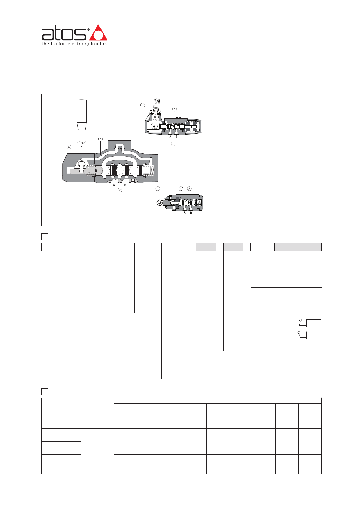
5
www.atos.com
*
*
*
*
Hand & mechanical directional valves
ISO 4401 sizes 06, 10, 16 and 25
DH-00
DP-21
body
spool
mechanical actuator without lever
lever
cam
DH-02
Table E150-13/E
Hand & mechanical operated directional
valves are spool type, three or four way,
two or three position valves, available with
following actuator types:
- mechanical actuator: general purpose
exec ut io n fo r conne ct io n to cus to me r
device for the valve’s remote operation
- hand-lever
- cam (only for DH and DK).
Valve sizes and max flow:
DH-0 = size 06, flow up to 50 l/min
DK-10 (11)
DK-12
DP-2 = size 16, flow up to 300 l/min
DP-4 = size 25, flow up to 700 l/min
Max pressure:
350 bar for DH-0, DP-2, DP-4
315 bar for DK-1*
= size 10, flow up to 100 l/min
= size 10, flow up to 140 l/min
1 MODEL CODE
DH-0
Directional control valve, size:
DH-0 = 06
DP-2 = 16
DP-4 = 25
Type of actuator:
0 = mechanical, without lever
1 = hand-lever
2 = cam (only for DH-0 and DK-1)
Valve configuration, see sections and
0 = free, without springs
1 = spring centered, without detent
2 = retun to internal position
3 = return to external position
4 = 3 position, with detent
5 = 2 external positions, with detent
6 = centre plus external positions, with detent
7 = return to external position from the centre position
8 = return to the centre position from the external position
2 RANGE OF VALVE’S MODELS
VALVE TYPE SIZE
DH-00
DH-01
DH-02
DK-10
DK-11
DK-12
DP-20
DP-21
DP-40
DP-41
06
10
16
25
1
0
쩨
쩨
쩨쩨쩨쩨쩨쩨쩨쩨쩨
쩨쩨쩨쩨쩨쩨쩨쩨쩨
1
12345678
쩨
쩨
쩨
쩨
쩨
쩨
Only for DH-01 hand-lever valves:
/C = short hand - lever and reducend actuation force
Spool type, see section
VALVE CONFIGURATION
쩨
쩨
쩨
쩨
쩨
쩨
쩨
쩨
쩨
쩨
A ** *C// /3
Seals material:
- = NBR
PE = FKM
Series number
Options:
/A = actuator device mounted on side of port B
Lever position to be specified for DH-00, DH-01
and DK-00, DK-01 with configuration 6, 7, 8, see
section for hydraulic connections:
/I = in rest position the lever is
inclined towards the valve body
/E= in rest position the lever is
inclined in opposite side
Only for DK-1:
/Y= external drain
쩨
쩨
쩨
쩨
쩨
쩨
쩨
쩨
쩨
쩨
쩨
쩨
쩨
쩨
쩨
쩨
쩨쩨
쩨쩨
쩨
쩨
E150
Page 23
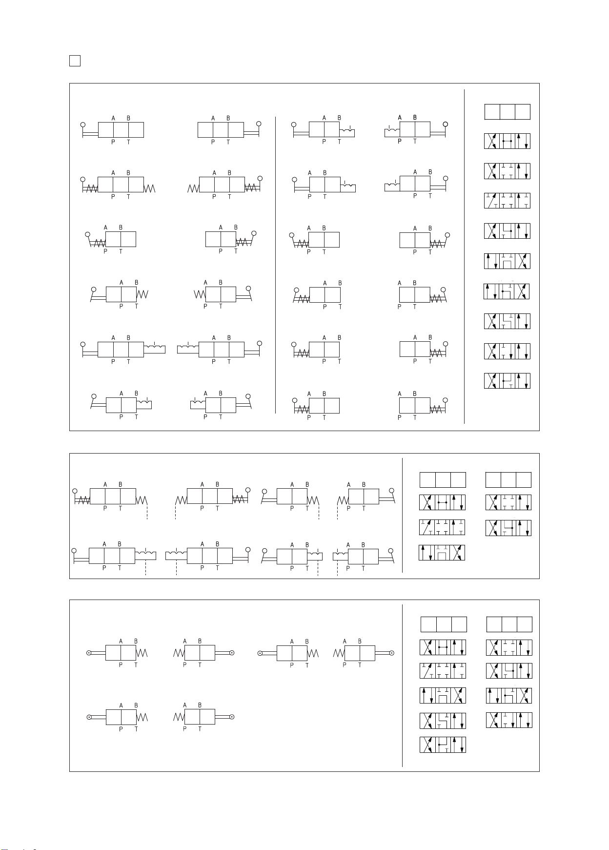
ONFIGURATIONS and SPOOLS - for intermediate passages, see tab. E001
0
1
0
1
0 2
0
1
0 2
02
0
0 2
0 2
0
1
0 2
0
1
0
1
01 0 2
0
1
2
0
1
2
0
1
2
0
1
2
1
2
1
2
1
2
1
2
0
1
2
0
1
2
1
2
1
2
01 0 2
0
1
2
0
1
2
0
1
2
0
1
2
1
2
1
2
1
2
1
2
01 0 2
01 0 2
1
2
1
2
1
0
0
2
0
2
0
1
01 0 2
C
3
r
e
v
le
d
n
a
h
d
n
a
l
a
ic
n
a
h
c
me
-
*
1
1
-
K
D
*,
0
1
-
K
D
nd
a
*
1
0
-
H
D
*,
0
0
-
H
D
Configurations
H-000* DK-100*
D
H-010* DK-110*
D
H-001* DK-101*
D
H-011* DK-111*
D
H-002* DK-102*
D
H-012* DK-112*
D
DH-000*/A DK-100*/A
DH-010*/A DK-110*/A
DH-001*/A DK-101*/A
DH-011*/A DK-111*/A
H-002*/A DK-102*/A
D
H-012*/A DK-112*/A
D
r
o
t
a
u
t
c
a
DH-006*/E DK-106*/E
DH-016*/E DK-116*/E
DH-006*/I DK-106*/I
DH-016*/I DK-116*/I
H-007*/E DK-107*/E
D
H-017*/E DK-117*/E
D
DH-006*/EA DK-106*/EA
DH-016*/EA DK-116*/EA
DH-006*/IA DK-106*/IA
DH-016*/IA DK-116*/IA
DH-007*/EA DK-107*/EA
DH-017*/EA DK-117*/EA
0
1
(
3/1
pools
S
0
/1
1
/1
2
1)
3
DH-003* DK-103*
DH-013* DK-113*
DH-004* DK-104*
DH-014* DK-114*
H-005* DK-105*
D
H-015* DK-115*
D
DP-20*, DP-21*, DP-40*, DP-41* - hand lever actuator
DP-201* DP-401*
DP-211* DP-411*
DP-204* DP-404*
DP-214* DP-414*
DH-003*/A DK-103*/A
DH-013*/A DK-113*/A
DH-004*/A DK-104*/A
DH-014*/A DK-114*/A
H-005*/A DK-105*/A
D
H-015*/A DK-115*/A
D
DP-201*/A DP-401*/A
DP-211*/A DP-411*/A
DP-204*/A DP-404*/A
DP-214*/A DP-414*/A
Configurations
DP-203* DP-403*
DP-213* DP-413*
DP-205* DP-405*
DP-215* DP-415*
H-007*/I DK-107*/I
D
H-017*/I DK-117*/I
D
DH-008*/E DK-108*/E
DH-018*/E DK-118*/E
DH-008*/I DK-108*/I
DH-018*/I DK-118*/I
DP-203*/A DP-403*/A
DP-213*/A DP-413*/A
DP-205*/A DP-405*/A
DP-215*/A DP-415*/A
DH-007*/IA DK-107*/IA
DH-017*/IA DK-117*/IA
DH-008*/EA DK-108*/EA
DH-018*/EA DK-118*/EA
DH-008*/IA DK-108*/IA
DH-018*/IA DK-118*/IA
0
2
4
4
5
6
7
8
(1) Spool type 2
available only for DH
Spools
1
3
DH-02*, DK-12* - cam actuator
Configurations
DH-023*
DK-123*
DH-028*
DK-128*
DH-023*/A
DK-123*/A
DH-028*/A
DK-128*/A
NOTE
- Spools type 0/2, 1/2, 2/2 are only used for valves type DH-023*/2 and DK 123*/2;
DH-027*
DK-127*
DH-027*/A
DK-127*/A
Spools
0
0/2
2 (1)
2/2
4
6
8
(1) Spool type 2 available only for DH
1/2
1
3
5
7
Page 24
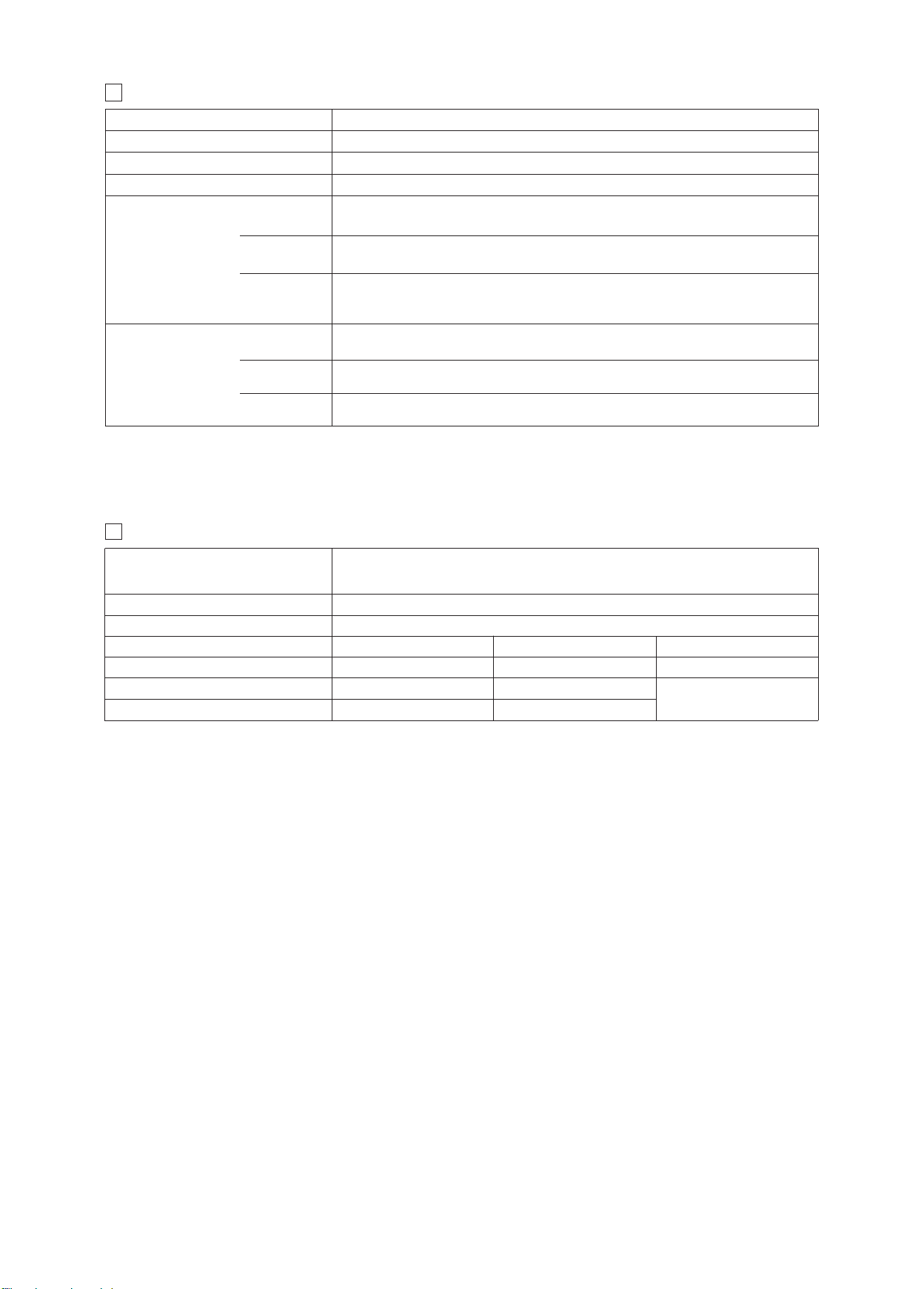
AIN CHARACTERISTICS
M
4
Assemby position Any position except for configurtion 7 (without spring) that must be installed with horizontal axis
Subplate surface finishing Roughness index Ra 0,4 - flatness ratio 0,01/100 (ISO 1101)
Ambient temperature from -30°C to +70°C (standard seals) -20°C to +70°C (/PE seals)
low direction As shown in the symbols of tables
F
Operating pressure
D
DK
, A, B = 350 bar
P
= 160 bar
H
T
, A, B = 315 bar
P
T = 160 bar
P, A, B, X = 350 bar
= 250 bar for external drain (standard)
DP
D
H
T
orts Y = 0 bar
P
0 l/min
5
Maximum flow
5
EALS AND HYDRAULIC FLUIDS - For other fluids not included in above table, consult our technical office
S
NBR seals = (standard) -30°C ÷ +60°C, with HFC hydraulic fluids = -20°C ÷ +50°C
Seals, recommended fluid temperature
DK-10, DK-11
K-12
D
P-2
D
P-4
D
Recommended viscosity 15÷100 mm
00 l/min
1
140 l/min
00 l/min
3
00 l/min
7
FKM seals = (/PE option) -20°C ÷ +80°C
2
/s - max allowed range 15 ÷ 380 mm2/s
Fluid contamination class ISO 4406 class 21/19/16 NAS 1638 class 10, in line filters of 25 mm (b25 _>75 recommended)
Hydraulic fluid
Mineral oils
Flame resistant without water
Flame resistant with water
Suitable seals type
NBR, FKM
FKM
NBR
Classification Ref. Standard
HL, HLP, HLPD, HVLP, HVLPD
HFDU, HFDR
HFC
DIN 51524
ISO 12922
E150
Page 25
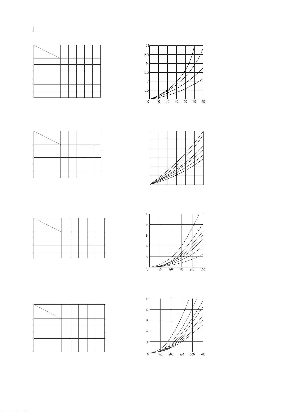
/DP DIAGRAMS based on mineral oil ISO VG 46 at 50°C
0255075
100
125
150
3
6
9
12
15
18
Q
6
DH-*
low direction
F
Spool type
0, 0/1, 0/2 C C C C
1, 1/1, 1/2 A A A A
2, 2/2, 3, 3/1 A A C C
4, 5 D D D D A
6, 7 A A C A
8 C C B B
씮A P씮B A씮T B씮T P씮T
P
H-*
D
D
B
A
C
Valve pressure drop Dp [bar]
low rate [l/min]
F
DK-*
Flow direction
Spool type
0, 0/1, 0/2 A A B B
1, 1/1, 1/2, 6, 8 A A D C
3, 3/1, 7 A A C D
4 B B B B E
5 A B C C F
P씮A P씮B A씮T B씮T P씮T
DP-2*
low
F
direction
Spool
type
1, 3 A A C A -
0 A A C D B
2 A A - - -
4 B B F G E
P씮AP씮BA씮TB씮TP씮T
DK-*
F
E
D
C
B
A
Valve pressure drop Dp [bar]
Flow rate [l/min]
DP-2*
G
F
E
D
C
B
A
Valve pressure drop Dp [bar]
DP-4*
Spool
type
1 A A A C -
0 C B C D E
2 A A - - -
3 A A C E -
4 B B F G G
Flow
direction
P씮AP씮BA씮TB씮TP씮T
Flow [l/min]
DP-4*
FG
E
D
C
B
A
Valve pressure drop Dp [bar]
Flow [l/min]
Page 26
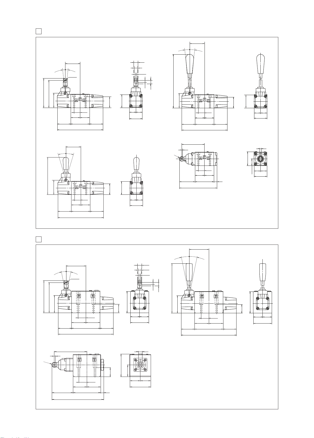
IMENSIONS OF HAND & MECHANICAL OPERATED VALVES ISO 4401 SIZE 06 [mm]
D
7
DH-00**
96
102.5
DH-01**/C
131
DH-01**
0
3
°
6
52
6
’
°
0
3
°
6
3
0
’
H8
5
Ø15
12
5
+0.1
.2
0
2
5
’
6
°
3
0
’
225
7.5
12.5
51
21.5
=
=
7
4
6
47
6
60
1
52
1
’
6
0
°
3
3
°
0
6
1
’
46
38.5
=
=
45
Mass: 1,2 Kg
DH-02**
51
21.5
=
=
7
66
7
4
60
1
4
79.85
.5
2
1
6
46
38.5
=
=
45
ass: 1,6 Kg
M
6
46
21.5
=
=
1
1
131.85
6
6
4.85
5
51
1.5
2
=
=
66
7
4
47
160
46
38.5
=
=
45
orking stroke: 2,5 mm; extra-stroke: 0,5 mm max.
W
SO 4401: 2005
I
ounting surface: 4401-03-02-0-05 (see table P005)
M
Fastening bolts: 4 socket head screws M5x50 class 12.9
Tightening torque = 8 Nm
=
=
23.5
45
Mass: 1,2 Kg
Diameter of ports A, B, P, T: Ø = 7,5 mm (max)
Seals: 4 OR 108
8
DIMENSIONS OF HAND & MECHANICAL OPERATED VALVES ISO 4401 SIZE 10 [mm]
+0.1
DK-11**
0
7.5
12.5
DK-10**
113
69
’
1
0
3
°
1
1
106.5
61.5
1
5H8
°
3
0
’
75
30
27
=
=
47
100
47
194
Ø15
12
5.2
=
=
65
Mass: 2,5 Kg
DK-12**
109
12
4
16
76
40
=
70
Mass: 2,5 Kg
=
70.9
173.1
30
27
=
=
92.2
10
Working stroke: 4 mm; extra-stroke: 0,5 mm max.
69
’
0
3
°
1
1
1
1
°
3
0
’
235
61.5
30
27
=
=
47
100
47
194
ISO 4401: 2005
Mounting surface:
4401-05-05-0-05 (see table P005)
(Without X port, Y port optional)
Fastening bolts: 4 socket head screws M6x40 class 12.9
Tightening torque = 15 Nm
Diameter of ports A, B, P, T: Ø = 11,2 mm (max)
Seals: 5 OR 2050
75
=
65
Mass: 2,8 Kg
=
E150
Page 27
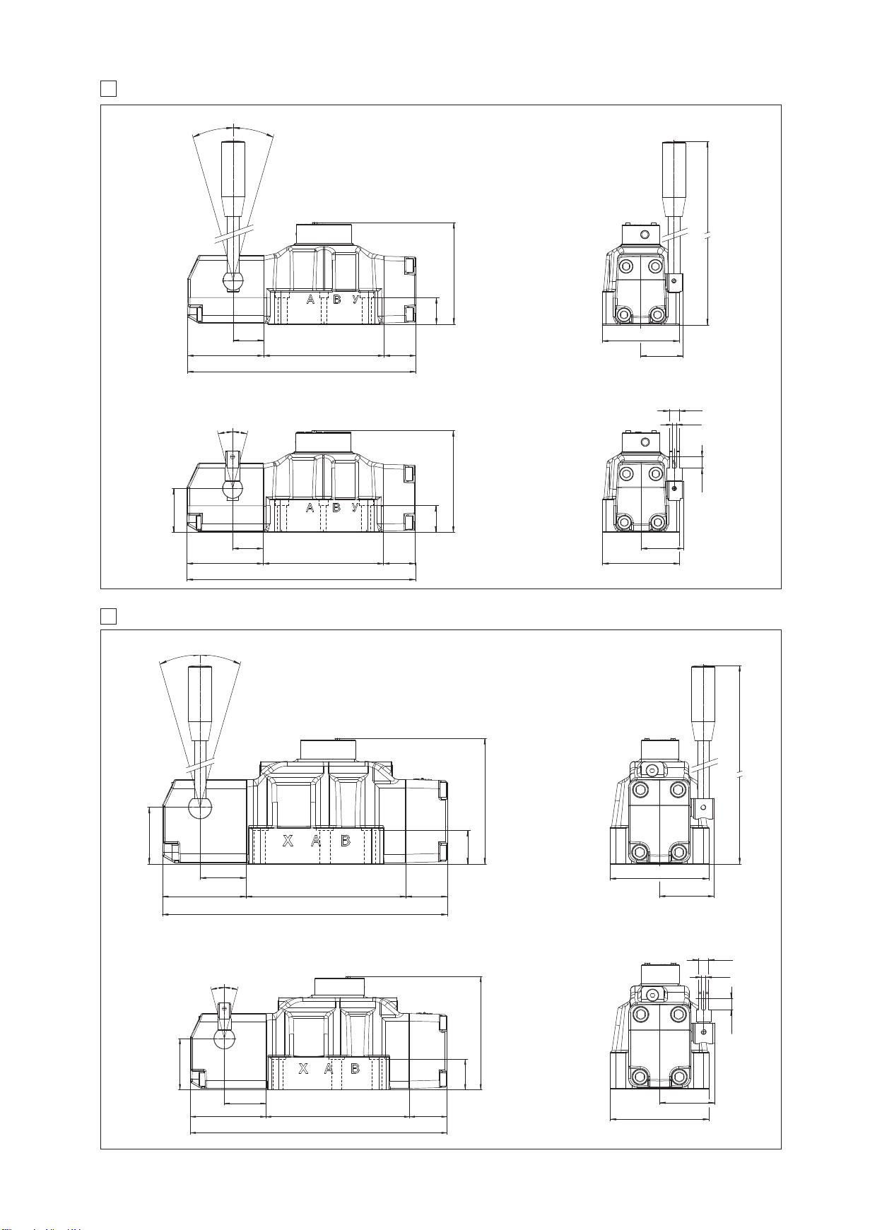
DIMENSIONS OF HAND & MECHANICAL OPERATED VALVES ISO 4401 SIZE 16 [mm]
8
P-21
D
6
2
2
’
6
0
3
°
°
3
0
’
ISO 4401: 2005
ounting surface: 4401-07-07-0-05 (see table P005)
M
astening bolts:
F
socket head screws M10x50 class 12.9, Tightening torque = 70 Nm
4
2 socket head screws M6x40 class 12.9, Tightening torque = 15 Nm
iameter of ports A, B, P, T : Ø = 20 mm
D
iameter of ports X,Y: Ø = 7 mm
D
eals: 4 OR 130, 3 OR 109/70
S
122
34
6.5
3
4492
1
74
2
8
3
ass: 10 Kg
M
DP-20
2
’
6
0
°
3
3
°
6
2
0
’
122
68
34
36.5
14492
74
2
38
ass: 9,7 Kg
M
9 DIMENSIONS OF HAND & MECHANICAL OPERATED VALVES ISO 4401 SIZE 25 [mm]
DP-41
3
1
°
1
3
°
ISO 4401: 2005
Mounting surface:
4401-08-08-0-05 (see table P005)
Fastening bolts:
6 socket head screws M12x50 class 12.9, Tightening torque = 125 Nm
Diameter of ports A, B, P, T : Ø = 24 mm
Diameter of ports X,Y: Ø = 7 mm
Seals: 4 OR 4112, 3 OR 3056
287
2
9
1
5
12
+0.1
0
5
13.5
51
92
DP-40
02/17
151
304
68
42
55
100 191
49.5
118
65.5
340.5
Mass: 15,5 Kg
12
+0.1
0
31°
31°
68
55
100 191 49.5
340.5
151
42
118
Mass: 15,2 Kg
5
12.5
65.5
Page 28
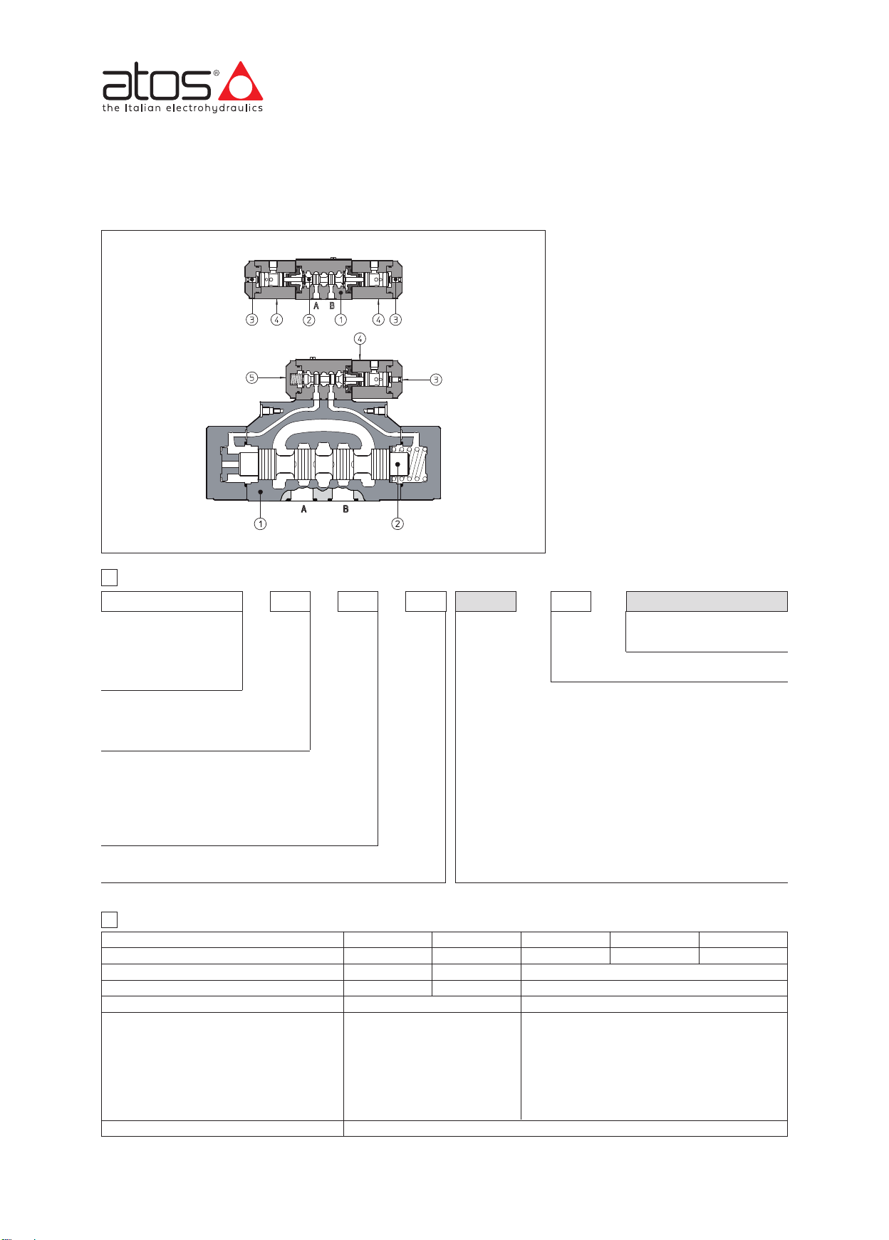
www.atos.com
Pneumatic operated directional valves
ISO 4401 sizes 06, 10, 16, 25 and 32
DH-09*
Main body
Spool
Manual override
Pneumatic actuator
Pilot valve
DPH-48*
Table E255-2/E
Pneumatic operated directional valves are
spo ol type , three or four way, two or
three position, designed to operate in oil
hydraulic systems.
Available with single or double pneumatic
actuator with manual override.
Valve sizes and max flow:
DH-0 = size 06, flow up to 50 l/min
DK-1 = size 10, flow up to 160 l/min
DPH-2 = size 16, flow up to 300 l/min
DPH-4 = size 25, flow up to 700 l/min
DPH-6 = size 32, flow up to 1000 l/min
Max pressure:
350 bar for DH-0, DPH-2, DPH-4, DPH-6
315 bar for DK-1
1 MODEL CODE
DH-0 8 1 3 A ** *//
Directional control valve, size:
DH-0 = 06
DK-1 = 10
DPH-2 = 16
DPH-4 = 25
DPH-6 = 32
Type of actuator:
8 = single actuator
9 = double actuator
Valve configuration, see sections 쪪 and
0 = free, without springs
1 = spring centered, without detent
3 = spring offset external position
5 = 2 external positions, with detent
7 = center and external positions
Spool type, see sections 쪪 and
2
HYDRAULIC CHARACTERISTICS
Valve model
Max recommended flow [l/min]
Max pressure on port P, A, B (also X for DP) [bar]
Max pressure on port T [bar]
Max pressure on port L and Y [bar]
Recommended oil pressure on piloting line [bar]
Recommended pneumatic pressure (1) [bar]
(1) filtered and lubricated air
쪫
쪫
DH-0
50
350
Seals material, see section 쪩:
- =
NBR
PE = FKM
Series number
Options:
only for valve with single actuator:
Actuator device mounted on side of port B (for DH and DK).
/A =
Actuator device mounted on side of port A of main body (for
DPH)
only for DPH:
/D = internal drain
/E = external pressure
/H = adjustable chokes for controlling the main spool shifting time
(meter-out to the pilot chambers of the main valve)
/H9= adjustable chokes for controlling the main spool shifting time
(meter-in to the pilot chambers of the main valve)
/R = pilot pressure generator on port P at 4 bar
/S = main spool stroke adjustment
DK-1
160
315
210
–
–
DPH-2
300
The device /R generates an additional pressure drop, in
order to ensure the minimum pilot pressure, for correct
operation of the valves with internal pilot and fitted with
spools type 0, 0/1, 4, 4/8, 5, 58, 09, 90, 94, 49. The device
/R has to be fitted when the pressure drop in the valve,
verified on flow versus pressure diagrams, is lower than
the minimum pilot pressure value.
Min = 2 Max = 12
DPH-4
700
350
250
null pressure
Min = 4 Max = 250
DPH-6
1000
E255
Page 29
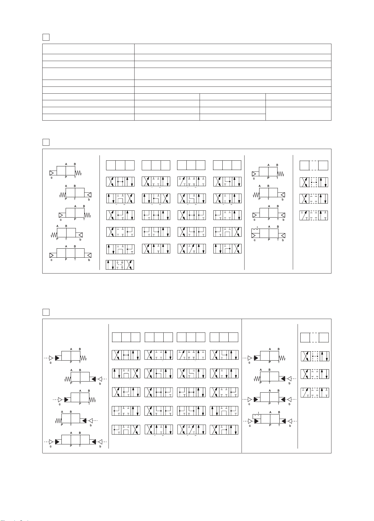
MAIN CHARACTERISTICS, SEALS AND FLUIDS - for other fluids not included in below table, consult our technical office
2
1
0 2
1
2
1
0 2
0
1
2
1
2
1
0 2
1
0
1
0 2
0 2
0
1
2
1
01 0 2
2
1
01 0 2
01 0 2
01 0 2
01 0 2
01 0 2
01 0 2
01 0 2
01 0 2
01 0 2
1 0
2
0
1 0
2
1
3
ny position for all valves except for type -*90 (without springs) that must be installed with horizontal
Assembly position / location
Subplate surface finishing Roughness index Ra 0,4 - flatness ratio 0,01/100 (ISO 1101)
Ambient temperature Standard execution = -30°C ÷ +70°C; /PE option = -20°C ÷ +70°C;
NBR seals (standard) = -20°C ÷ +60°C, with HFC hydraulic fluids = -20°C ÷ +50°C
Seals, recommended fluid temperature
Recommended viscosity 15÷100 mm
Fluid contamination class ISO 4406 class 21/19/16 NAS 1638 class 10, in line filters of 25 mm (b25 _>75 recommended)
Hydraulic fluid
Mineral oils
Flame resistant without water
Flame resistant with water
4 CONFIGURATIONS and SPOOLS of valves type DH-*, DK-*
FKM seals (/PE option) = -20°C ÷ +80°C
A
axis if operated by impulses.
2
s - max allowed range 2.8 ÷ 500 mm
/
Suitable seals type
BR, FKM
N
FKM
BR
N
2
s
/
Classification Ref. Standard
L, HLP, HLPD, HVLP, HVLPD
H
FDU, HFDR
H
HFC
IN 51524
D
SO 12922
I
Configurations
81
87
87/A
91
NOTES
- spools type 0 and 3 are also available as 0/1 and 3/1 with restricted oil passages in central position, from user ports to tank.
- spools type 1, 4, 5 and 58 are also available as 1/1, 4/8, 5/1 and 58/1. They are properly shaped to reduce water-hammer shocks during the swiching.
- spools type 1, 1/2, 3, 8 are available as 1P, 1/2P, 3P, 8P (only for DH-0) to limit valve internal leakages.
5
CONFIGURATIONS and SPOOLS of valves type DPH-*
Configurations Spools Configurations Spools
Spools
0
1/A
8
4
8
9
1
49
nly for DH
o
1/9
1
5
0
9
only for DH
3
9
16
only for DH
0
3
17
2
6
9
9
only for DH*
nly for DH
o
only for DH
3
7
1
9
4
9
only for DH
58
Configurations Spools
83
0/2
83/A
1/2
90
2/2
5
9
spool type 2/2
only for DH-*
81
81/A
87
87/A
91
Special shaped spools
- spools type 0 and 3 are also available as 0/1 and 3/1 with restricted oil passages in central position, from user ports to tank.
-
spools type 1, 4, 5, 58, 6 and 7 are also available as 1/1, 4/8, 5/1, 58/1, 6/1 and 7/1 are properly shaped to reduce water-hammer shocks during the switching.
0
4
8
19
49
NOTE
For DPH-6 are available only spools: 0, 1, 1/2, 2, 3, 4, 5, 58, 6, 7, 8, 19, 91
1
5
90
93
16
2
6
09
39
17
3
7
91
94
58
83
83/A
90
95
0/2
1/2
2/2
Page 30
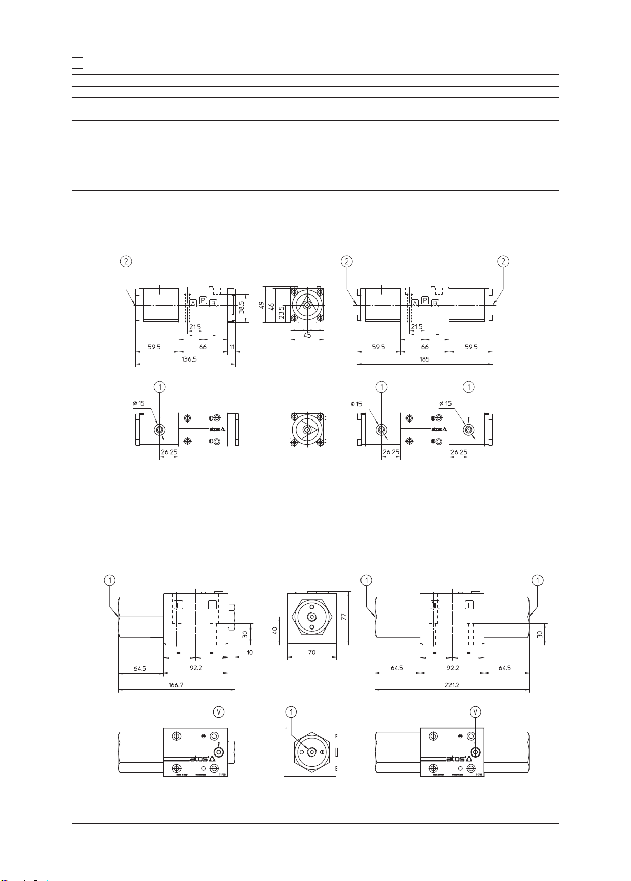
/Dp DIAGRAMS
Q
6
DH-0 See note and diagrams on table E010 relating the DH* valve from which DH-0* are derivated
DK-1 See note and diagrams on table E025 relating the DKE valve from which DK-1* are derivated
DPH-2 See note and diagrams on table E085 relating the DPH*-2 valve from which DP-2* are derivated
DPH-4 See note and diagrams on table E085 relating the DPH*-4 valve from which DP-4* are derivated
DPH-6 See note and diagrams on table E085 relating the DPH*-6 valve from which DP-6* are derivated
INSTALLATION DIMENSIONS of VALVES type DH and DK [mm]
7
ISO 4401: 2005
Mounting surface:
Fastening bolts: 4 socket head screws M5x50 class 12.9
Tightening torque = 8 Nm
Diameter of ports A, B, P, T: Ø = 7,5 mm (max)
eals: 4 OR 108
S
4401-03-02-0-05
DH-08**
DH-09**
Mass: 1,2 Kg
Mounting subplates: see tab. E010
ISO 4401: 2005
Mounting surface:
Fastening bolts: 4 socket head screws M6x40 class 12.9
Tightening torque = 15 Nm
Diameter of ports A, B, P, T: Ø = 11,2 mm (max)
Seals: 5 OR 2050
4401-05-04-0-05
DK-18**
Pilot pressure port G1/8”
Manual override
Mass: 1,6 Kg
DK-19**
Mass: 3,4 Kg
Mounting subplates: see tab. E025
Pilot pressure port G1/4”
Air bleed
Mass: 4,2 Kg
E255
Page 31
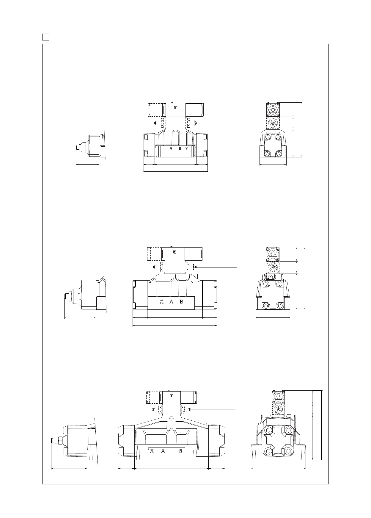
NSTALLATION DIMENSIONS of VALVES type DP [mm]
I
8
PH-2
D
SO 4401: 2005
I
Mounting surface:
Fastening bolts:
socket head screws M10x50 class 12.9
4
Tightening torque = 70 Nm
socket head screws M6x45 class 12.9
2
ightening torque = 15 Nm
T
Diameter of ports A, B, P, T : Ø = 20
iameter of ports X,Y: Ø = 7 mm
D
4401-07-07-0-05
Seals: 4 OR 130, 2 OR 2043
troke adjustment
S
evice for option /S
d
Only for option /H
49
40
186
97
85 max
PH-4
D
ISO 4401: 2005
Mounting surface:
astening bolts:
F
socket head screws M12x60 class 12.9
6
ightening torque = 125 Nm
T
4401-08-08-0-05
Diameter of ports A, B, P, T: Ø = 24
Diameter of ports X,Y: Ø = 7 mm
Seals: 4 OR 4112, 2 OR 3056
Stroke adjustment
device for option /S
109 max
8
8
3
144
220
3
nly for option /H
O
2
9
Mass: 11,5 Kg
40 49
215
126
19149.5 49.5
290
118
Mass: 18 Kg
DPH-6
ISO 4401: 2005
Mounting surface:
4401-10-09-0-05
Fastening bolts:
6 socket head screws M20x80 class 12.9
Tightening torque = 600 Nm
Diameter of ports A, B, P, T: Ø = 34 mm
Diameter of ports X,Y: Ø = 7 mm
Seals: 4 OR 144, 2 OR 3056
Stroke adjustment
device for option /S
132 max
02/17
Only for option /H
27560 60
395
49
40
256.5
167.5
200
Mass: 39,5 Kg
Page 32
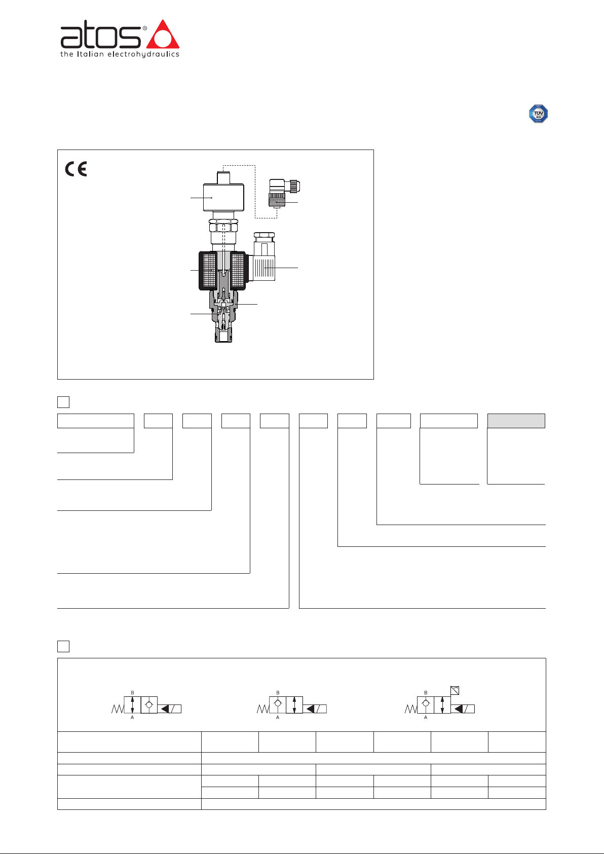
G
T
able
EY105-0/E
Safety cartridge valves
with optional poppet position monitoring
screw-in, 2-way, poppet type, leak free, conforming to Machine Directive 2006/42/CE - certified by
O-DL are leak free, poppet type solenoid
J
cartridges in screw-in execution normally
sed to cut off the hydraulic power supply
u
ine. They are available in normally closed
l
NC, or normally open one NO configurations.
he /FV version integrates an inductive
T
osition switch (double contact NC/NO)
p
b wich supplies the output electrical on-
ff signal indicating the poppet x position
o
open/closed), and therefore they can be
(
used as safety valves for emergency conditions.
hey are CE marked and certified by TÜV
T
in accordance with safety requirements of
achine Directive 2006/42/CE.
M
Certification
he TÜV certificate can be downloaded
T
rom www.atos.com, catalog on line, tech-
f
nical information section.
ax flow: 300 l/min
M
ax pressure: 350 bar
M
artridge body
c
oppet
p
oil
c
oil connectors
c
nductive position switch
i
sensor connector
(to be ordered separately)
BE-06
Z
A
B
JO-DL-4-2/FV-X 24DC
1
MODEL CODE
JO
Cartridge valve
screw-in type UNF
D = Directional control
L = Poppet type
Size:
4 = 3/4”-16UNF-2A
6 = 7/8”-14UNF-2A
5/16
10 = 1
2 = Two-way
Note (1): not for version /FV
2 HYDRAULIC CHARACTERISTICS
Hydraulic symbols
”-12UNF-2A
D L
/NO /NC /FV
--/
-
4 2 NC X
-/
X = Without connector, see section 5 for available connector
Version:
NC=normally closed in rest position
NO=normally open in rest position
FV =normally closed in rest position, with inductive position switch
(double contact)
24 DC ** *
Series number:
20 for FV
for NC and NO
40
Voltage code:
12DC = 12 V
24DC = 24 VDC
DC
Seals material,
see section 4:
- =
NBR
PE = FKM
BT = HNBR (1)
Model
Operating pressure [bar]
Max flow [l/min]
Response time: energizing [ms]
de-energizing [ms]
Internal leakage
JO-DL-4-2/NC
JO-DL-4-2/FV
35 50 30 50 35 150
50
JO-DL-4-2/NO
40
35 60 35 70 35
less than 5 drops/min (≤ 0,36 cm
JO-DL-6-2/NC
JO-DL-6-2/FV
Ports A and B 350
JO-DL-6-2/NO
75 300
3
/min) max at 350 bar
JO-DL-10-2/NC
JO-DL-10-2/FV
JO-DL-10-2/NO
EY105
Page 33
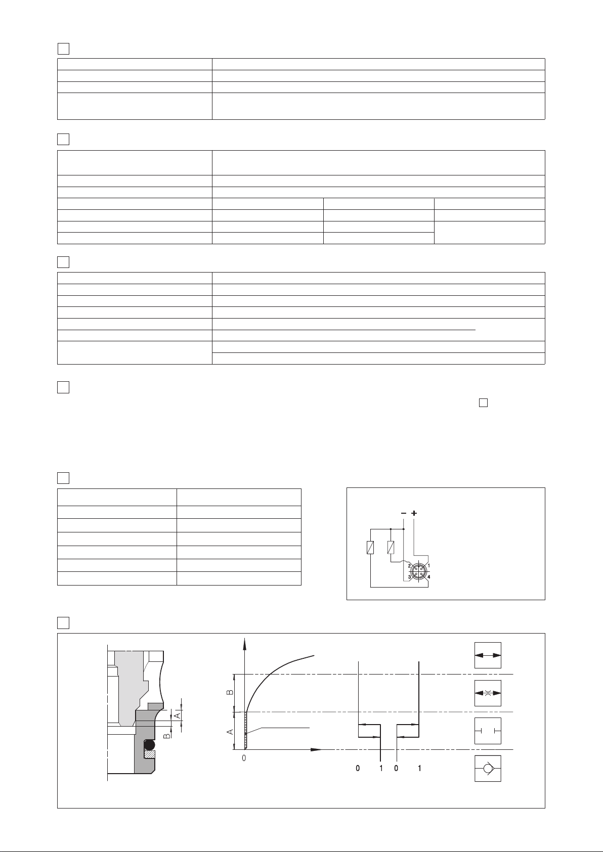
GENERAL CHARACTERISTICS
3
Installation position Any position
Cavity JO-DL-4 = SAE-08-2N; JO-DL-6 = SAE-10-2N; JO-DL-10 = SAE-16-2N
MTTFd values according to EN ISO 13849 150 years, for further details see technical table P007
Standard execution = -30°C ÷ +70°C
Ambient temperature /PE option = -20°C ÷ +70°C
/BT option = -40°C ÷ +70°C - not for version /FV
SEALS AND HYDRAULIC FLUID
4
NBR seals (standard) = -20°C ÷ +60°C, with HFC hydraulic fluids = -20°C ÷ +50°C
Seals, recommended fluid temperature FKM seals (/PE option) = -20°C ÷ +80°C
HNBR seals (/BT option) = -40°C ÷ +60°C, with HFC hydraulic fluids = -40°C ÷ +50°C
Recommended viscosity 15÷100 mm
for other fluids not included in below table, consult
-
2
s - max allowed range 2.8 ÷ 500 mm
/
tos Technical Office
A
2
s
/
Fluid contamination class ISO 4406 class 21/19/16 NAS 1638 class 10, in line filters of 25 µm (β10 _>75 recommended)
ydraulic fluid
H
ineral oils
M
lame resistant without water
F
Flame resistant with water
5 ELECTRIC CHARACTERISTICS
Suitable seals type
BR, FKM
N
KM
F
BR
N
lassification Ref. Standard
C
HL, HLP, HLPD, HVLP, HVLPD
HFDU, HFDR
FC
H
IN 51524
D
SO 12922
I
Relative duty factor 100%
Supply voltage See model code at section
1
Supply voltage tolerance ±10%
Max power 19 Watt
Power connector 666 (plastic - black); 3 pins, cable clamp PG11, cable max ø 11 mm
Type of connector for /FV version Type ZBE-06 (plastic); 4 pins, cable clamp PG9, cable max ø 8 mm
Connectors features
ZBE-06: M12 - IEC60947-5-2; IP67 (DIN 40050)
INSTALLATION NOTES
6
1) The assembling of cartridges inside manifolds must be done tightening the valve exagonal ring (for tightening torque, see section ).
Excessive values can cause anomalous deformation and poppet sticking.
For the /FV versions avoid to tighten through the position sensor.
2) The CE certification is valid only with shielded electric cables and connector. Consult also tab. P004.
These safety valves must be supplied only and always as one complete component, proximity sensor is factory adjusted.
The supply of subcomponents invalidates the certification.
666: DIN 43650 - ISO 4400; IP65 (DIN 40050); VDE 0110C
o be ordered
t
separately
0
1
7
TECHNICAL CHARACTERISTICS AND CONNECTING SCHEME OF INDUCTIVE POSITION SWITCH /FV
Type of switch
Supply voltage [V]
Ripple max [%]
Max current [mA]
Max peak pressure [bar]
Mechanical life
Switch logic
position switch /FV
20÷32
≤ 10
400
400
virtually infinite
PNP
Connector type
NO
NOTE: the /FV position switch are not provided with a protective earth connection
8
SIGNAL STATUS - VERSIONS /FV
stroke
leakage
flow Q
pin 2 pin 4
NC
SIGNAL
ZBE-06
1 = supply +24 VDC
2 = output signal NC
3 = GND
4 = output signal NO
A: overlapping stroke
B: damping stroke
According the criteria of safety specifications, the poppet position signal must change its status
inside the overlapping stroke (before the effective valve opening).
Page 34

9
IAGRAMS based on mineral oil ISO VG 46 at 50°C
D
.1 JO-DL-4
9
Valve pressure drop - NO version
1=A씮 B de-energized
2=B씮 A de-energized
3= B 씮 A energized
5
1
2
1
3
2
1
9
Valve pressure drop - NC version
4=A씮 B energized
5=B씮 A de-energized
6=B씮 A energized
5
1
2
1
9
Valve pressure drop - FV version
7=A씮 B energized
8=B씮 A de-energized
9=B씮 A energized
5
1
5
6
4
12
8
7
9
9
6
3
Valve pressure drop ∆p [bar]
0
10 20
Flow rate [l/min]
.2 JO-DL-6
9
Valve pressure drop - NO version
1=A씮 B de-energized
2=B씮 A de-energized
3= B 씮 A energized
0
2
16
12
8
4
Valve pressure drop ∆p [bar]
0 20 40
Flow rate [l/min]
60
6
3
Valve pressure drop ∆p [bar]
40
0
3
0
10 20
40
0
3
Flow rate [l/min]
Valve pressure drop - NC version
4=A씮 B energized
5=B씮 A de-energized
3
2
1
6=B씮 A energized
0
2
16
12
5
6
4
8
4
Valve pressure drop ∆p [bar]
80
0 20 40
60
80
Flow rate [l/min]
6
3
Valve pressure drop ∆p [bar]
0
0 20
1
Flow rate [l/min]
Valve pressure drop - FV version
7=A씮 B energized
8=B씮 A de-energized
9=B씮 A energized
20
16
12
8
4
Valve pressure drop ∆p [bar]
0 20 40
Flow rate [l/min]
60
30
4
80
0
8
9
7
9.3 JO-DL-10
Valve pressure drop - NO version
1=A씮 B de-energized
2=B씮 A de-energized
3= B 씮 A energized
20
16
12
8
4
Valve pressure drop ∆p [bar]
0 75 150
Flow rate [l/min]
225
300
Valve pressure drop - NC version
4=A씮 B energized
5=B씮 A de-energized
1
2-3
6=B씮 A energized
20
4
5-6
16
12
8
4
Valve pressure drop ∆p [bar]
0 75 150
225
300
Flow rate [l/min]
Valve pressure drop - FV version
7=A씮 B energized
8=B씮 A de-energized
9=B씮 A energized
20
16
12
8
4
Valve pressure drop ∆p [bar]
0 75 150
Flow rate [l/min]
225
8-97
300
EY105
Page 35
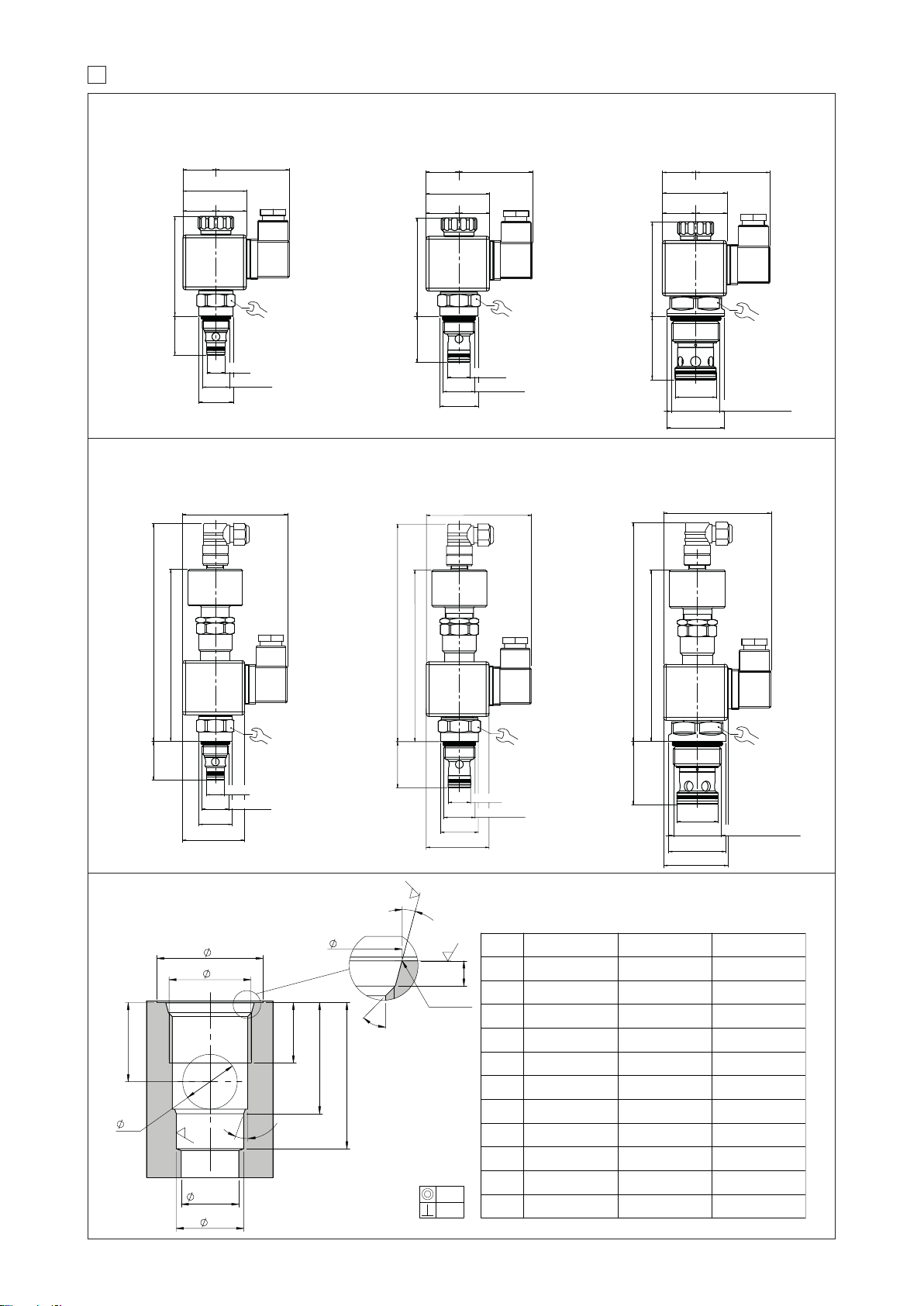
0
B
A
F
L1
L2
D1
2
0
°
G1
max.
G
H1
1.6
R
0,20
4
5
°
E
1
5
°
C
3.2
1
.
6
0.03
0.02
A
3/4-16 UNF 7/8-14 UNF
1 5/16-12 UNF
B
26 30 42
C
20.6
+0,1
0
23.9
+0,1
0
35.5
+0,1
0
D1
12.7
+0,05
0
15.87
+0,05
0
28.60
+0,05
0
E
2.6
+0,3
0
2.6
+0,3
0
3.3
+0,3
0
F
13 15 20
G
91219
G1
12 15 24
H1
14 18 25
L1
20.5 25.5 36
L2
29 34.5 49
1
IMENSIONS [mm]
D
ersion /NO and /NC
V
O-DL-4-2/N*
J
Mass 0.35 Kg
7.5x36
4
3.5 19
2
O-DL-6-2/N*
J
Mass 0.35 Kg
52.523.5
23.5 19
52.523.5
47.5x36
O-DL-10-2/N*
J
Mass 0.4 Kg
3.5
2
7.5x36
4
23.5 19
52.5
Version /FV
156 max27.5
70
27.5
Ø
12.7
3/4-16 UNF-2A
Ø
24
JO-DL-4-2-2/N*/FV
ass 0.5 Kg
M
76
122 max
2
5
4
0 Nm
70
32.5
JO-DL-6-2/N*/FV
ass 0.5 Kg
M
167 max
133 max
Ø
26.8
Ø
15.87
7/8-14 UNF-2A
76
7
2
62 Nm
66
44
Ø
JO-DL-10-2/N*/FV
ass 0.7 Kg
M
163 max44
129 max
28.6
Ø
0
4
1 5/16-12 UNF-2A
6
7
6
3
132 Nm
CAVITY DIMENSIONS
Note: cavity compatible
with old cartridge series
05/18
Ø
24
47.5x36
Ø
12.7
3/4-16 UNF-2A
24
50 Nm
27
Ø
15.87
7/8-14 UNF-2A
62 Nm
Ø
28.6
Ø
40
47.5x36
32.5
Ø
26.8
47.5x36
36
132 Nm
1 5/16-12 UNF-2A
SAE-08-2N SAE-10-2N SAE-16-2N
Page 36
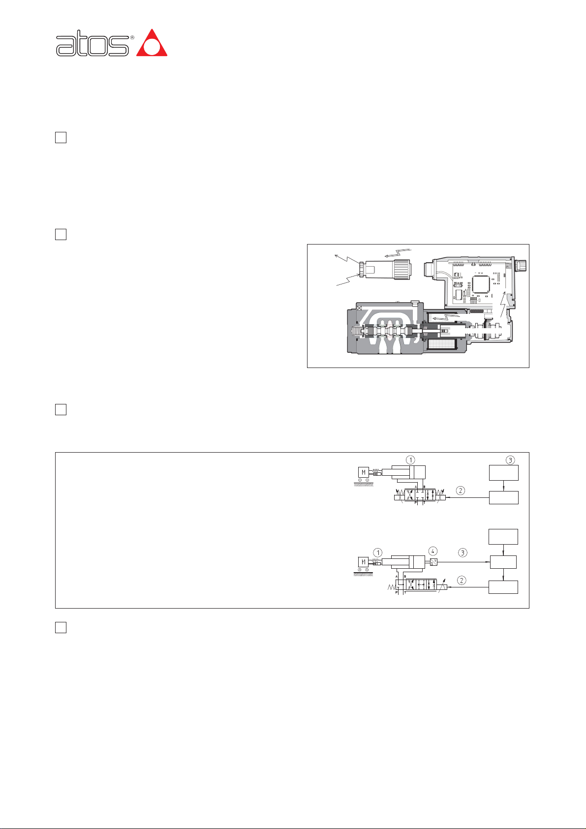
The core of electrohydraulic controls is the proportional valve that
regulates a pressure P or a flow Q according to the reference input
signal (normally ±10 V
DC
) supplied by the machine CNC. Particularly the
proportional valve must be operated by an electronic driver (see tab.
G001) which regulates a proper electrical current supplied to the valve’s
solenoid according to the reference signal. The solenoid converts the
electrical current into a mechanical force acting the spool against a
return spring: rising of the current produces a corresponding increasing
in the output force and consequent compression of the return spring,
thus the movement of the spool. The proportional valves can be single
stage or piloted, with or without pressure/position transducer.
Proportional valves with transducer provide better regulation accuracy.
In pilot operated executions the proportional pilot valve regulates flow
and pressure acting on the main operated stage.
When electrical failure occurs, return springs restore the neutral position
according to valve configuration, to ensure a fail-safe operation, i.e. to
ensure that in case of absence of reference signal or, generally, in case of electric system breakdown, the system configuration does not
cause damages. Fail-safe can be realized directly by the proportional valve (fail-safe operation intrinsic in valve configuration) or it can be
realized by consequential operation of a group of valves.
Atos valves may be spool type or cartridge execution and can be grouped in three different functional families:
• pressure control valves: relief valves and reducing valves regulate the hydraulic system pressure proportionally to the reference input signal;
• 4-way directional control valves: direct and modulate the flow to an actuator proportionally to the reference input signal. These valves can be
used in open or closed loop control system to determine the direction, speed and acceleration of actuators;
• flow control valves: 2 or 3-way, pressure compensated, to modulate the flow independently to the user loads.
4 PROPORTIONAL VALVES AND DRIVERS
Atos proportional valves are equipped with ZO and ZOR, efficient solenoids (30 W and 40 W) respectively designed for direct-acting valves of
ISO 4401 size 06 and 10 and they are assembled in different options as follows:
ZO(R)-A: without integral transducer, open loop;
ZO(R)-AE, AES: as ZO-A plus integral electronic driver, analog or digital;
ZO(R)-T, -L: with integral LVDT single/double position transducer, closed loop, featuring high static and dynamic performances;
ZO(R)-TE, -LE, -LES: as ZO-T, -L plus integral electronic driver, analog or digital
In the new generation of -AE, -TE, -LE valves, the electronic driver is integral to the proportional valves and it is factory preset to ensure fine
functionality plus valve-to-valve interchangeability and to simplify installation wiring and system set-up. Electronics are housed and resin
encapsulated in a metal box to IP67, ensuring antivibration, antishock and weather-proof features; coils are fully plastic encapsulated.
For detailed information on Electronic drivers, see tab. G001
SOLENOID FORCE
CURRENT
POWER SUPPLY 24 V
DCMONITOR
REFERENCE SIGNAL
PRESSURE P
FLOW Q
FEEDBACK
ELECTRONIC DRIVER
Fig. 1
쏟
쏟
쏟
www.atos.com
Basics for proportional electrohydraulicsmensioni ISO/Cetop 07 e 08
Table F001-9/E
1 WHAT IS PROPORTIONAL ELECTROHYDRAULICS?
F001
Electrohydraulic proportional controls modulate hydraulic parameters according to the electronic reference signals.
They are the ideal interface between hydraulic and electronic systems and are used in open or in closed-loop controls, see section 쪩, to achieve the fast, smooth and accurate motions required by today’s modern machines and plants.
The electrohydraulic system is a section of the overall automation architecture unit where information, controls, alarms can be transmitted in a
“transparent” way to the centralized electronic control unit and viceversa also via standard fieldbus, see tab. F002 for “Basics for digital electrohydraulics”.
Proportional electrohydraulics provides the following advantages in comparison with the electromechanical systems; intrinsic overload protection, automatic force adaption, fast operating response, self lubrification of the system, simple stepless variation in speed, energy storage
capability, high power density, forces and torques, long service life and high reliability.
3 CONTROL LOOPS
Today industrial machines are multi-axis machines, more and more electrohydraulically controlled by proportional devices. The axis motion can
be operated in “open loop” or in “closed loop” control, depending to the accuracy level required in the application. In many applications the
motion cycles do not require extreme accuracy, so they are performed in open loop, while each time the application requires the positioning of an
actuator, a closed loop control must be provided.
2 WHAT IS A PROPORTIONAL VALVE?
햲
= ACTUATOR
햳
= PROPORTIONAL VALVES AND DRIVERS
햴
= ELECTRONIC CONTROLLER
햵
= ACTUATOR’S TRANSDUCER
Fig 2: Electrohydraulic axes: a basic block diagrams
OPEN LOOP MOTION CONTROL
CLOSED LOOP MOTION CONTROL
Axis control is provided through the supply of a reference input signal to the driver of
the proportional valve.
There is no feedback of the valve’s regulated hydraulic parameter.
The accuracy of the open loop controls is strictly dependent of the good quality of the
hydraulic system and particularly of the proportional valve and of the relevant driver.
Axis control is provided through the supply of an input reference signal to a closed loop axis controller which receive the feedback signal from the actuator transducer. The controller compares the two signals and the resulting error is then
processed to the proportional valve, in order to align its regulation to the PID control loop requirements.
The accuracy of the closed loop controls is much better respect to the open loop
ones and it is less influenced by the external environmental disturbances, thanks
to the presence of the feedback.
Anyway the best is the overall quality of the hydraulic system, the best is the
accuracy of the axis control.
CENTRAL
PROCESSING
UNIT
AXIS
CONTROLLER
DRIVER
VALVE’S
REFERENCE
SIGNAL
VALVE’S
REFERENCE
SIGNAL
CENTRAL
PROCESSING
UNIT
FEEDBACK
CENTRAL
PROCESSING
UNIT
DRIVER
DRIVER
REFERENCE
SIGNAL
SPRING
REACTION
Page 37
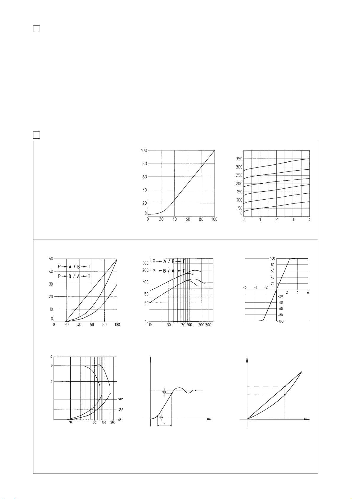
6 TYPICAL DIAGRAMS OF PROPORTIONAL CONTROLS
Valve’s-regulated pressure variation
according to the reference signal
Valve’s-regulated pressure variation according to the flow passing through the valve
6.1 PRESSURE CONTROL VALVES
Reference signal [% of max]
Regulated pressure [% of max]
Flow rate [l/min]
Regulated pressure [bar]
Regulated flow vs. functional Δp at max reference input signal
Pressure variation on use ports depending to
the spool stroke (only for valves with zero
overlapping in rest position).
Valve’s-regulated flow variation according to the
reference input signal
Pressure gain diagram
6.2 DIRECTIONAL AND FLOW CONTROL VALVES
Valve pressure drop 욼P [bar]
Flow [l/min]
Reference signal [% of max]
Max flow [l/min]
욼P A→B [%Pp]
The time lag required by the valve to reach
the requested hydraulic ragulation in front of
a step change in the reference input signal
(usually 0÷100%).
Response time is measured in millisecond
[ms] from 10 to 90 % of the step valve.
The curve shows for typical regulation ranges
(±5% and ± 90%) at different sinusoidal reference input signal frequency:
A) amplitude ratio variation, between reference
input signal and the regulated spool position
output signal;
B)
phase lag between reference input signal and
the regulated spool position signal.
The maximum difference in the valve regulation between reference input signal from 0 to
maximum and than from maximum to zero.
Hysteresis is measured in percentage of the
maximum value of the regulated hydraulic
parameter.
Response time Reference signal
Regulated parameter
Frequency [Hz]
Amplitude ratio [dB]
Regulated parameter
Operating diagramRegulation diagram
Regulation diagram at characteristic 욼p
Regulation diagram at max reference signal
Spool stroke [%]
Bode diagram HysteresisResponse time - step input
A1 A2
B1 B2
07/09
Phase [degree]
Repeatability: The maximum difference in the valve’s hydraulic regulation repeating the same input reference signal. Repeatability is measured
in percentage of the maximum value of the regulated hydraulic parameter.
Overlap: Percentage of spool stroke, starting from the central position, in which the valve remain closed.
Fail safe: spool’s safety hydraulic configuration in absence of electrical power supply
Linear spool: provides linear correspondence between valves regulation and reference input signal
Progressive spool: provides progressive regulation for finest low flow control
Differential spool: as progressive but with P-B = 50% of P-A
Leakage: The flow passing through port P to tank port T with the valve spool in central position. It is directly connected with the quality of the
valve’s mechanical execution.
Reference input signal: The electric signal sent from machine CNC to the valve electronic driver to obtain the required regulation value.
Driving current: The current sent from the electronic driver to the valve’s solenoid.
Bias current: Static offset added to the reference input signal required to compensate positive overlap spools.
Dither: The pulse frequency of the driver regulation used to minimize the valve hysteresis.
Regulation scale: Setting of the valve regulation with the max reference signal.
Ramp time: Time (in sec.) required to smoothly operate the valve in front of a step reference input signal.
5 TYPICAL ELECTROHYDRAULIC TERMS
Page 38
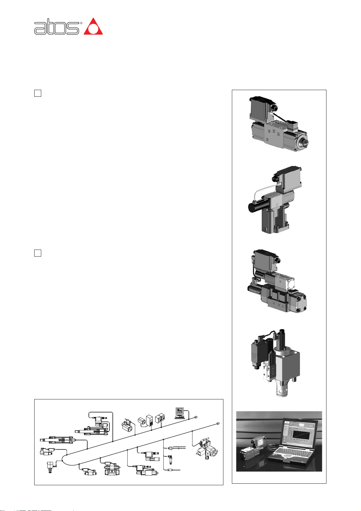
www.atos.com
Digital electrohydraulics
Table F002-4/E
F002
2 COMMUNICATION INTERFACES
1 DIGITAL TECHNOLOGY FOR PROPORTIONAL VALVES
The communication interface is the channel trough which the valve receives commands
and/or setting parameters and it returns information to the fieldbus controller.
Atos digital proportional valves are available with 3 optional communication interfaces:
• basic -PS: standard RS232 interface, to be coupled to an user-friendly PC software
(E-SW-PS) optimized with grafic interface, for the management of all the functional
parameters, see tab. G500.
The main feature of this basic version is the full interchangeability with the
corresponding analog executions, in fact the reference and the monitor signals are
analog, whereas the serial interface allows to manage the diagnostics and to set the
best configuration of the valve for the application’s requirements.
This approach enables a gradual introduction of the advantages of digital technology,
without perturbing the whole application/machine’s structure.
• option -BC: CANBus (CanOpen DS408 v1.5 protocol)
• option -BP: Profibus-DP (Fluid Power Technology protocol).
The valves with option -BC and -BP can be connected to the fieldbus network and thus
digitally operated by the machine control unit.
The functional parameters can be set via fieldbus using the standard communication
protocol implemented by Atos, or alternatively using the PC graphic software E-SW-PS
with the relevant USB interface supplied with the software KIT (see fig. 2 and tab.
G500). For start-up or maintenance operations, the valves with -BC or -BP interfaces
can be operated with analogue signals via the 7 (or 12) pins power supply connector.
Modern world is driven by digital electronics: computers, automation systems, cars and
missiles, telecomunications and advanced network are all based on digital
technology… …thanks to its typical benefits in comparison with analog: fast and
powerful data processing, easy programmability, high immunity to electromagnetic
noise, process parameters and data storage.
In electrohydraulics, digital electronics gives important advantages:
• better performances of electrohydraulic components: hysteresis, response time,
linearity;
• numerical software setting of hydraulic parameters (scale, bias, ramp, compensation
of non-linearities) for full repeteability and easy data storage
• diagnostic (fault, monitor) and computer assisted maintenance of machines and
systems;
• direct interfacing to field-bus networks.
Atos, leader in pioneering proportional electrohydraulics, is active from years on digital
electrohydraulics including: simulation models of valves and systems, research and
testing of new DSP microcontrolles, R&D of new solutions.
New digital electrohydraulics with on board electronics enable new funcionalities within
the conventional control architectures and represent the foundamental premise to
realize new compact machines with high technological contents.
The digital electronics integrate several logic and control functions (distributed
intelligence) and make it feasible and inexpensive the introduction in the hydraulic
system of the most modern fieldbus communication networks.
Atos digital driver’s range replicate the analogue one:
• E-RI-AES for valves without transducer
• E-RI-TES/LES for valves with single/double LVDT transducer
• E-RI-TERS for valves with pressure transducer
AZC electrohydraulic
servo actuator
AZM
electrohydraulic
servomotor
Servo axis
controllers and
inverters
Central control unit
Actuators with integral
position transducers
Safety hydraulic
valves
AES proportional valves
Temperature
TES Prop. valves
Transducers
Position
Pressure
PERS
Servo-controlled
hydraulic pumps
fieldbus
DKZOR-AES
AGMZO-TERS
DPZO-TES
LIQZO-LES
fig. 1
fig. 2 software setting of digital proportionals
Page 39
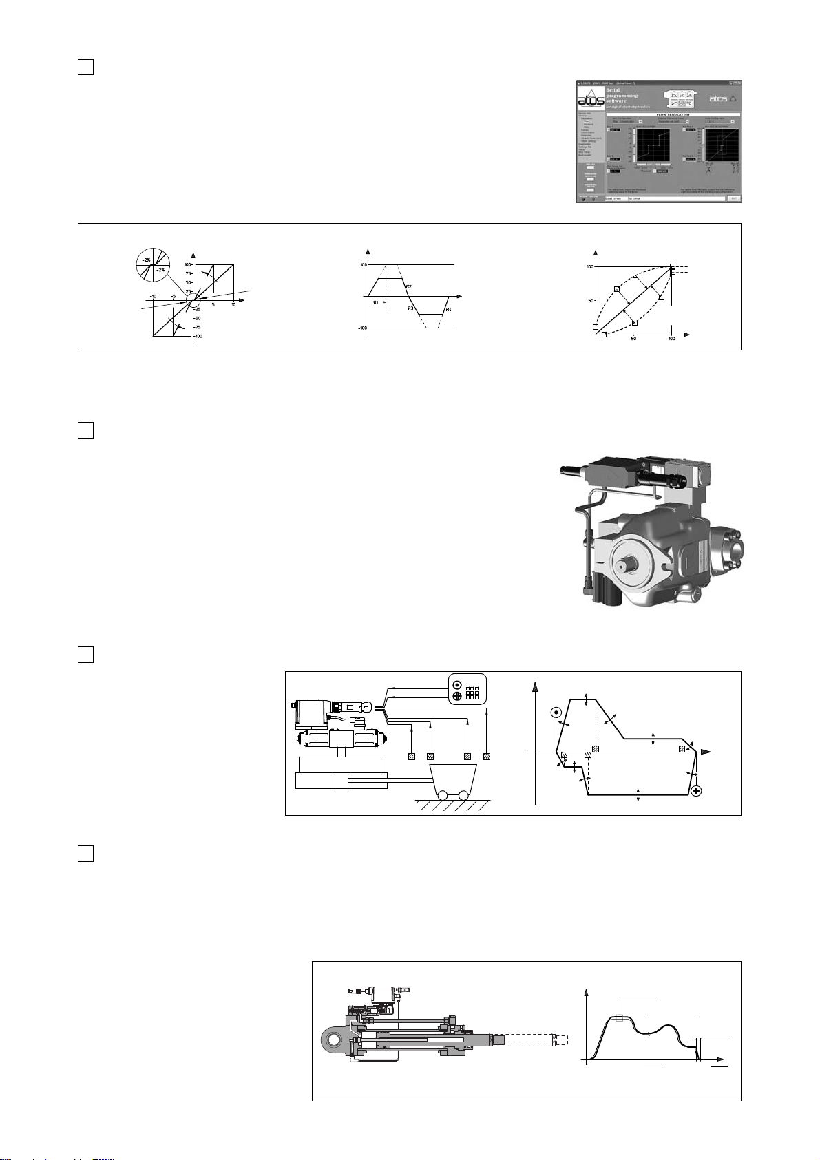
The concept of distributed
intelligence is applied in its easiest
form to the drivers type E-RI-AEG,
see fig. 8 and tab. G120.
This controller self-manages open
loop “fast-slow” positioning cycles,
interfacing up to five inductive
proximity sensors.
For any of the cycle phases it is
possible to set speed and ramps.
This solution has been developped
for applications with repetitive
cycles. The complete cycle is
managed by the valve itself without
auxiliary axis controller.
DIGITAL SOLUTIONS FOR BASIC SERVOSYSTEMS
5
Speed
Start forward
Start backward
Forward
V1
R2
V2
R3
Position
Backwards
V4
R5
V5
R6
R1
R4
f1 f2 f3 f4
Machine
control
unit
f1
f2
f3
f4
Servoactuators integrate several control functions within the driver itself, thus realizing truly compact electrohydraulic motion units.
E-RI-TEZ drivers for servoactuators, see fig. 9, besides driving the valve on which they are integrated, also perform a position, speed
and/or force control on the actuator itself.
For the end user, the main advantages of this kind of servosystems are:
• the self management of the motion control, with no need of using external axis cards
• the reduced number of wirings, thanks to the direct connection of the electronics to the peripherial sensors.
The distributed intelligence permits to locally manage the “fast” signals required by high performances closed loop controls, avoiding to
unnecessarily overload the fieldbus
communication line.
Application of such servoactuator solutions
takes place for example:
• for closed loop speed/position and
pressure control of the injection phase in
plastic presses
• for speed and force control of the moulds
closing in plastic presses
• for parison control is blow moulding
machines
• for master/slave syncronism in wood
machines and bending presses.
DIGITAL SERVOACTUATORS
6
11/05
A large number of the functional parameters of the valve can be numerically set trough the
communication interface, as:
• the bias and scale (fig. 4)
• the ramps, corresponding to the transition time from 0% to 100% of the valve’s regulation (fig. 5)
• the linearization of the regulation curve, allows to modify the hydraulic regulation of any valve,
as linearizing the characteristic of pressure control valve or change from linear to progressive
the characteristic of a directional control valve (fig. 6).
Many other regulations are available like: customized configuration of the reference signal
(standard ± 10 V), internal static self generation of the reference signal, dither signal, PID
parameters for dynamic behaviour, alarm setting of the high/low limits of the electronics
temperature, etc.
3 DIGITAL SETTINGS AND DIAGNOSTICS
4 COMBINED P/Q CONTROLS FOR DIRECTIONAL VALVES AND PUMPS
S1
S2
Scale - Settings
Scale - Settings
Adjustable
regulation
characteristic
Reference [%]
Time [sec]
Bias Setting
Bias Setting
UP AND DOWN RAMPS LINEARIZATIONSCALE AND BIAS
Regulated pressure [%] Regulated pressure [%]Regulated pressure [%]
Reference [V]
fig. 4 fig. 5 fig. 6
Detailed diagnostics information can be checked through the communication interface. They allow a complete analysis of the component
state and of its eventual malfunctionings, as for example:
• real time monitoring of the reference signal, of the feedback signals and of the electronics temperature
• alarm in case one of the above parameters overcome the set limits
• alarm in case of interruption of the feedback cable
Position
gains (Gp)
Speed gains (Gs)
Speed
Position
Reference cycle Real cycle
Error window
The high computing capability of Atos digital electrohydraulic and its great flexibility allow to realize
new functionalities:
• new drivers E-RI-TES with /SP and /ZP options perform the combined pressure and flow control
on directional control valves. A remote pressure transducer must be installed on the system
where is required the max pressure control and its feedback has to be interfaced to the valve. If
the real value of the pressure in the system (measured by the pressure transducer) remains
below the relevant reference signal, provided by the machine controller, then the digital driver
regulates in closed loop the valve’s spool position, according to the flow reference signal. When
the real pressure become close to the relevant reference signal, the driver automatically performs
the closed loop control of the pressure. This option allows to realize accurate dynamic pressure
profiles. A multiple set of PID parameters can be real time selected during the axis motion via onoff signal to the 12 poles connector (option /SP) or through the - BC or -BP interfaces (option /ZP),
to optimize the control performances in the different phases of the machine cycle.
• new drivers E-RI-PES for variable displacement axial piston pumps (see fig. 7), integrate the
digital combined pressure and flow control (see above) with an electronic max power limitation.
A multiple set of PID parameters can be real time selected during the axis motion via the 12 pin
connector (option /S) or through the -BC or -BP interfaces (option /Z), to optimize the P/Q control
performances.
fig. 7
fig. 8
fig. 9
fig. 3 Software graphic interface
Page 40
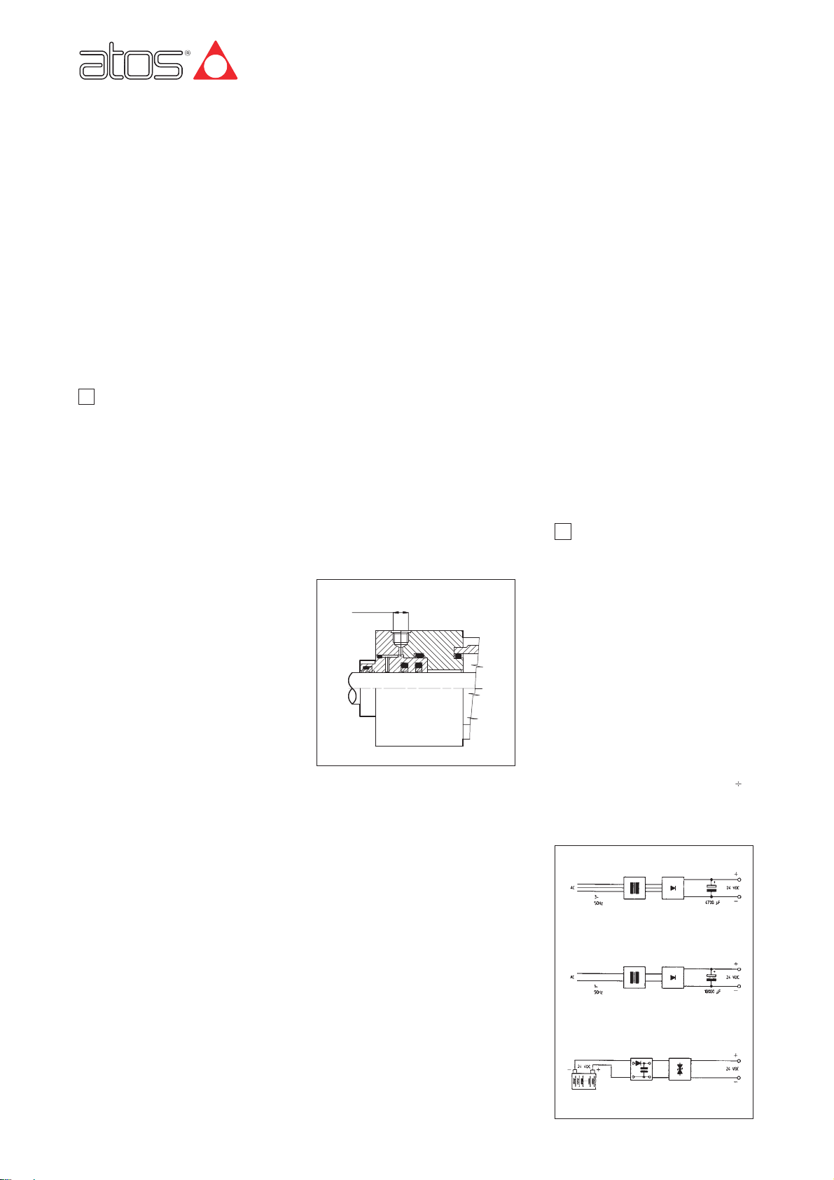
Electrohydraulic controls: commissioning and trouble shooting
due stadi, pilotate, dimensioni ISO/Cetop 07 e 08
Table F003-6/E
1 HYDRAULIC SECTION
F003
The following notes give some general suggestions and cautions on the procedures to ensure the good operation of an electrohydraulic system, with
particular reference to the closed-loop circuits, typical of modern electrohydraulic axes and of high-performances proportional components with integral
analog and digital electronics. For more detailed information about specific components see the relevant technical tables. For proper operation of electrohydraulic components, following prescription must be respected.
1.1 Tank and tubes cleaning
1.2 Connections
1.3 Filtration
1.4 Hydraulic drains and return lines
1.5 Hydraulic fluid
1.6 Fluid conditioning
1.7 Air bleeds
2 ELECTRONIC SECTION
2.1 Power supply
2.2 Electrical cabling
2.3 Suppression of interferences by electri-
cal noise
2.4 Use of the service signals
2.5 Electronic calibrations
2.6 Temperatures and environments
3 INTEGRAL ELECT. WIRING SECTION
4 COMMAND SIGNALS WIRING
5 SHIELD CONNECTIONS
3.1 Standard version
3.2 Option /I
3.3 Option /Q
3.4 Option /F
3.5 Option /S and /Z
3.6 Option /Z for digital drivers
3.7 Option /SP and /ZP for digital drivers
1.1 Power packs tank and tubes cleaning
Power unit tank has to be accurately cleaned, removing all the contaminants and any
extraneous object; piping has to be cold
bended, burred and pickled. When completely assembled an accurate washing of the
piping (flushing) is requested to eliminate the
contaminants; during this operation the proportional valves have to be removed and
replaced with by-pass connections, or on-off
valves.
1.2 Hydraulic connections
The flexible hoses have to be armoured type
on pressure line between powerpack an
d
proportional
valve and on return line from
proportional valve. If their potential breackage may cause damages to any machine or
system or can cause injure to the operator, a
proper retenction (as the chain locking at
both the pipe-ends) or alternately a protecting carter must be provided.
The proportional valve must be installed as
close as possible to the actuator, to assure
the maximum stiffness of the circuit and so
the best dynamic performances.
1.3 Hydraulic fluid
Use only good quality fluids according to
DIN 51524..535, with high viscosity index.
The recommended viscosity is 15÷100
mm
2
/sec at 40°C. When fluid temperature
exceeds 60°C select viton seals for components; in any case the fluid temperature must
not exceed 80°C.
1.4 Fluid filtration
The fluids filtration prevent the wearing of the
hydraulic components caused by the contaminans present in the fluid.
Fluid contamination class must be in accordance to ISO 18/15 code by mounting in line
pressure filter at 10∝m value and β
10=75.
In line filters must be mounted, if possible,
immediately before proportional valve; the filtering element is high cracking pressure type
with clogging electrical indicator, without bypass valve.
The flushing (at least 15 min. long) has to be
performed at the system commissioning to
remove the contaminants from the whole circuit.
After this
operation
filtering elements and flushing accessories cannot be used again, if
clogged.
Following additional warnings to be considered:
- make sure that the filters are of correct size
to ensure efficiency;
- the main source of contamination of an
hydraulic system is the air exchanged with
the environment: proper air filte rs on the
power unit tank to be always provided;
- filter the fluid when filling the tank (new
fluid is contaminated) with filtration Group
GL-15 (table L150) or similar.
1.5 Hydraulic drains and return lines
The function of drains is essential in all
systems, because they define the minimum
pressure level.
They must be connected to the tank without
counter-pressures.
Drain connections is provided on tie rod side
of the servocylinder, see figure.
Return line from proportional valve to tank
has to be sized in order to avoid variable
counter pressure < 1 bar; for this reason it is
recommended to use multiple separated
return lines directly connected to tank.
1.6 Fluid conditioning
A high-performance system must be thermally conditioned to ensure a limited fluid temperature range (generically between 40 and
50°C) so that the fluid viscosity remains constant during operation.
The operating cycle should start after the
prescribed temperature has been reached.
1.7 Air bleeds
Air in the hydraulic circuits affects hydraulic
stiffness and it is a cause of malfunctioning.
Air bleeds are provided in the proportional
valves and servocylinders; air dump valves
must be
inserted
at possible air accumulation points of the hydraulic system.
Following additional warnings to be considered:
on starting the system all the bleeds must be
released to allow removal of air. In particular
for servocylinders be careful to bleed the
transducer chamber, which is done by releasing the dump valve at the rod end;
- for the piping untight the connections;
- the system must be bled on first start-up
or after maintenance;
- use a precharged check valve (e.g. to 4
bars) on the oil general return line to tank
to avoid emptying of the pipes following a
long out of service.
2.1 Power supply
The voltage values to be within the following
range (depending on the type of supply
devices):
nominal voltage: V = 24 V
DC
;
filtered and rectified voltage: Vrms=21÷33 V
(ripple max = 2Vpp);
The supply device must be sized in order to
generate the correct voltage when all utilities
require max current at same time; in general
50W max intake electrical power can be considered for each supplied valve.
Following additional notes to be considered,
see figure below:
- power supply from a battery: overvoltages
(typically greater than 34 Volts) damage
the electronic circuits; it is recommended
the use of suitable filters and voltage suppressors;
- rectified AC power supply: the average
value to be within the limit Vrms = 21
28
Volts, with a supply capacitor equal to
10000 µF for each 3A of current expected
when single-phase power supply; 4700 µF
when three-phase power supply.
1
HYDRAULIC SECTION
DRAIN
1/8” GAS
2 ELECTRONIC SECTION
RECTIFIER
RECTIFIED AND FILTERED THREE-PHASE POWER SUPPLY
RECTIFIED AND FILTERED SINGLE-PHASE POWER SUPPLY
DIRECT CURRENT POWER SUPPLY
TRANSFORMER
TRANSFORMER
RECTIFIER
SUPPRESSOR
FILTER
OVERVOLTAGE
SUPPRESSOR
www.atos.com
Page 41

2.2 Electrical wiring
The power cables (coils, electronic adjusters
or other loads) to be separated from the
control cables (references and feed-backs,
signal grounds) to avoid interferences.
The electrical cables of the electronic signals
must be shielded as indicated in section 쪫
with shield or cablebraid connected to the
ground (according to CEI 11-17).
Recommended cable cross section;
- Supply and earth: 0,75 mm
2
;
- Coils: 1mm
2
(Lmax = 20 m); 1,5 mm2(for
longer distance) of shielded type;
- Voltage reference and LVDT feedback:
0,25mm
2
(Lmax = 20m) of shielded type;
Note: current reference signals options must
be provided when greater lengths apply to
reference and feedback connections;
suitable electronic units and transducers or
voltage to current converters are available.
- Service signal: 0,25mm
2
(Lmax = 20 m) of
shielded type;
- Electronic transducers: 0,25mm
2
(Lmax =
20 m) of shielded type;
2.3 Suppression of interferences by
electrical noise
When starting the system, it is always advisable to check that feedbacks, references and
signal grounds are free from interferences
and electrical noise which can affect the
characteristics of the signals and generate
instability in the whole system.
Electrical noises are high non-stationary
oscillations both on amplitude and frequency
around the signal average value; they can be
suppressed by shielding and grounding the
signal cables, see section 쪫.
Most of electrical noises are due to external
magnetic fields generated by transformers,
electric motors, switchboards, etc.
2.4 Integral drivers service signals and
options
- Monitor signal (standard)
The output signal (0÷5V, ±10V) is available to monitor the current to the solenoid
(AE, AES) or the spool position of the
valve (TE, LE, TES, TERS). Both signals
can be connected to main control unit for
sequence operations and diagnostics.
Note: electrical monitor signals taken via
valve electronics must not be used to switch off the machine safety functions. This is
in accordance with the European regulations standard (Safety requirements fluid
Technology systems and components);
- Current reference signal (option /I)
It provides the 4÷20 mA current reference
signal and the current feedback signals
instead of the standard 0÷10V (± 10V). It
is normally used in case of long distance
between the machine control unit and the
valve or where the reference signal can
be affected by electrical noise. In case of
breakage of the reference signal cable,
the valve functioning is disabled.
- Fault signal (option /F)
Safety option providing an output signal
which switches to zero in case of interruption of the transducer feedback cable. In
this condition the valve functioning is disabled.
- Enabling contact (option /Q)
Safety option providing the possibility to
enable or disable the valve functioning
without cutting the power supply.
- Fail safe conditions
In case of no feedback signal due to
shortcircuit or break in the transducer
cabling, an automatic inhibition of the control card operates and zero current is fed
to valves. At the same time a LED (inside
the housing for the integral electronics) is
signalling the emergency condition.
- Logic state signals for E-RI-TE and
E-RI-LE (option /S)
This function gives three output signal in
order to control in real time the valve’s
spool position to allow the diagnostic controls. The signal “Zero position” is “on”
(22V 20 mA) when the spool is in the central position, while the other two signals
(“Position S1” and “Position S2”) are
“on” when the spool is moving according
to the excitation of the S1 or S2 solenoid,
respectively. This safety signals can be
used to switch-off the machine safety
functions.
- Enable fault and monitor for E-RI-TE
and E-RI-LE (option /Z)
Option providing the same characteristics
of /F and /Q plus the monitor signal 0 ÷ 10
V (or ± 10 V) of the spool position.
- Double power supply enable and fault
for E-RI-TES, E-RI-TERS, E-RI-LES
(option /Z)
Safety option, specifically introduced for -BC
and -BP fieldbus interfaces, provides two
separated power supplies for the digital electronic circuits and for the solenoid power
supply stage. The Enable and Fault signals
are also available. The option /Z allows to
interrupt the valve functioning by cutting the
solenoid power supply (e.g. for emergency,
as provided by the European Norms EN954-1
for components with safety class 2), but keeping energized the digital electronic circuits,
thus avoiding fault conditions of the machine
fieldbus controller.
- P/Q control for E-RI-TES-PS and
E-RI-LES-PS (option /SP)
Option providing in addition to the standard valve functions, a closed loop control
of the max pressure regulated by the proportional valve in the system, thus realizing a P/Q regulation. A remote pressure
transducer must be installed on the
system and its feedback has to be interfaced to the valve. If the real value of the
pressure in the system remains below the
relevant reference signal, the driver regulates in closed loop the valve’s spool position, according to the flow reference
signal. When the real pressure become
close to the relevant reference signal, the
driver automatically performs the closed
loop control of the pressure. This option
permits to realize accurate dynamic pressure profiles. Up to 4 set of PID pressure
parameters can be real time selected
during the axis motion via on-off signals to
the main 12 poles connector to optimize
the control performances in the different
phases of the machine cycle.
- P/Q control for E-RI-TES-BC (-BP) and
E-RI-LES-BC (-BP) (option /ZP)
Integral digital P/Q controller providing the
same characteristics of option /SP plus
additional double power supply, enable
and fault. In this option the multiple set of
PID pressure parameters can be real time
selected during the axis motion through
the -BC or -BP interfaces.
- Current feedback signal for E-RI-PES
(option /C)
The pump electronics is set to receive
4÷20 mA feedback signal from the remote
pressure transducer, instead of the standard 0÷10 V.
- P/Q control for E-RI-PES-PS (option /S)
Option providing up to 4 set of PID pressure parameters can be real time selected
during the axis motion via on-off signals to
the 12 poles connector to optimize the
control performances in the different phases of the machine cycle.
- P/Q control for E-RI-PES-BC (-BP)
(option /Z)
Integral digital P/Q controller providing the
same characteristics of option /SP plus
additional double power supply, enable
and fault. In this option the multiple set of
PID pressure parameters can be real time
selected during the axis motion through
the -BC or -BP interfaces.
2.5 Electronic calibrations
The valves with integral electronics normally
don’t need any calbration by final customer
because these operations have been already
performed before delivery of component (the
valves with integral electronics are used
more and more for their easier servicing and
improved reliability).
However Bias adjustment is allowed, to permit the regulation between the input reference electrical zero and the spool center position (actuator in a steady position); a new
calibration can be executed with particular
hydraulic conditions (i.e. cylinder with high
differential ratio value and/or high ∆p pressure operations). When electronic regulators in
Eurocard or other format are installed in the
control unit, the setting procedures are
shown on related technical tables; consult
them carefully before proceeding with the
start-up. Personalised calibrations in case of
particular requirements can be carried out
with the collaboration of Atos technical dept.
2.6 Temperatures and environments
Always chek that the operating environment
is compatible with the data given in the product tables. If necessary provide conditioning of the electronic cabinet.
In particular the integral electronics cannot
be used when ambient temperature is higher
than +60°C or lower than -20°C (-20°C to
+50 °C for digital -TERS execution).
Page 42
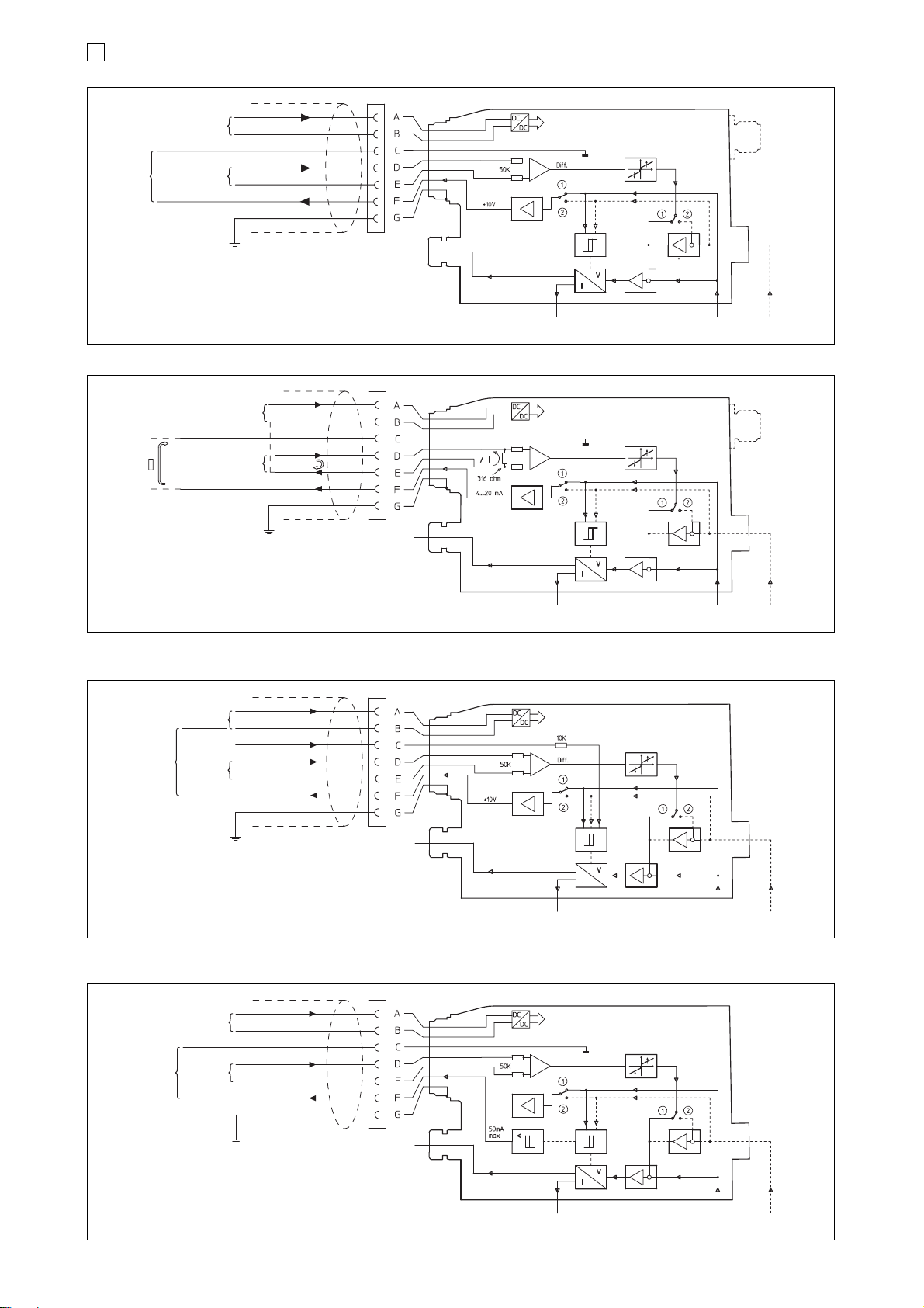
3.1 E-RI-AE (-AES), E-RI-TE (-TES), E-RI-LE (-LES), E-RI-TERS Standard versions
3.2 E-RI-AE, E-RI-TE, E-RI-LE, E-RI-TERS Option /I
FEEDBACK
(pilot stage E-RI-LE, E-RI-LES-*)
MAIN STAGE
FEEDBACK
FEEDBACK
(pilot stage E-RI-LE)
MAIN STAGE
FEEDBACK
DEAD BAND
COIL S2
(E-RI-*-05H)
COIL S1
ALARM
CONTROLLER
MONITOR
CONTROLLER
DEAD BAND
COIL S2
(E-RI-*-05H)
COIL S1
ALARM
CONTROLLER
MONITOR
CONTROLLER
3 ELECTRONICS WIRING
POWER
SUPPLY
REFERENCE
SIGNAL
CURRENT MONITOR (AE, AES)
FEEDBACK MONITOR (TE, LE, TERS, TES, LES)
GROUND
PROTECTION
POWER
SUPPLY
REFERENCE
SIGNAL
CURRENT MONITOR (AE)
FEEDBACK MONITOR (TE, LE)
+ 24 V
DC
0 VDC
± 10 VDC (signal)
0 V
DC (signal)
+ 24 V
DC
0 VDC
4÷20 mA
GROUND
PROTECTION
R = 316 ohm
(max 500
ohm)
Test
Test
NOTE: for digital electronics with -BC and BP options, the connections
D-E-F can be used to operate the valve with analogue signals
during start-up or maintenance
3.3 E-RI-AE, E-RI-TE, E-RI-LE Option /Q
3.4 E-RI-TE, E-RI-LE Option /F
DEAD BAND
COIL S2
(E-RI-*-05H)
ALARM
CONTROLLER
MONITOR
CONTROLLER
POWER
SUPPLY
REFERENCE
SIGNAL
COIL S1
ENABLE
+ 24 VDC
0 VDC
>9 to +24 VDC
± 10 VDC
0 VDC
CURRENT MONITOR (AE)
FEEDBACK MONITOR (TE, LE)
GROUND
PROTECTION
Test
DEAD BAND
COIL S2
(E-RI-TE-05H)
ALARM
CONTROLLER
MONITOR
FAULT
CONTROLLER
POWER
SUPPLY
REFERENCE
SIGNAL
FEEDBACK
(pilot stage E-RI-LE)
MAIN STAGE
FEEDBACK
COIL S1
+ 24 VDC
0 VDC
0 VDC
± 10 VDC
0 VDC
GROUND
PROTECTION
Test
FEEDBACK
(pilot stage E-RI-LE)
MAIN STAGE
FEEDBACK
Page 43
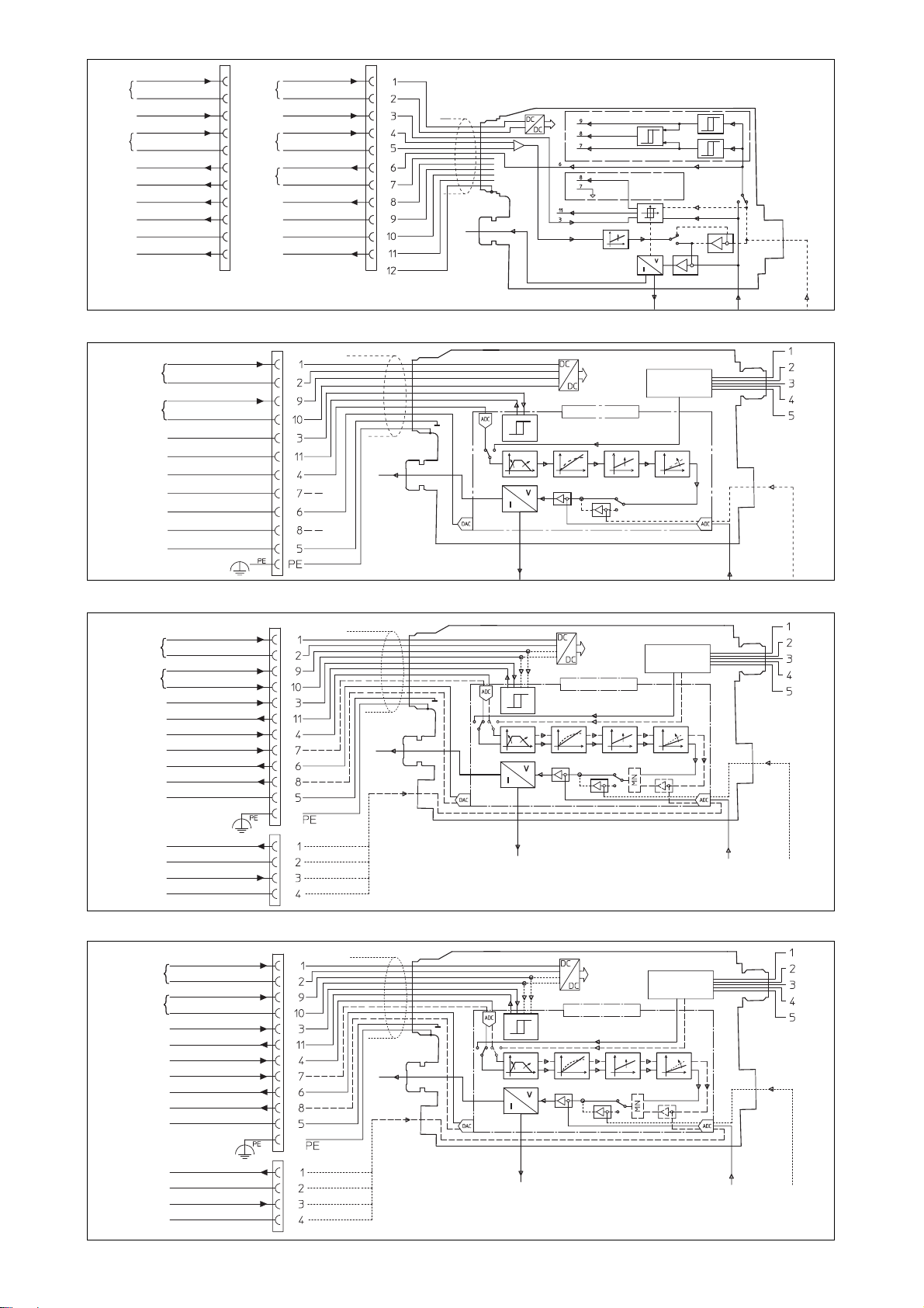
F003
3.5 E-RI-TE, E-RI-LE Option /S and /Z (12 pin connector)
3.6 E-RI-AES, E-RI-TES, E-RI-LES Option /Z (12 pin connector)
FEEDBACK
(pilot stage E-RI-LE)
COIL S2
(E-RI-TE-05H)
OPTION /S OPTION /Z
COIL S1
FEEDBACK
(pilot stage E-RI-LES)
COIL S1
MAIN STAGE
FEEDBACK
MAIN STAGE
FEEDBACK
OPTION /S
POSITION S2
POSITION ZERO
REPEAT
ENABLE
FAULT
MONITOR
DEAD
BAND
CONTROLLER
MICROCONTROLLER
CONTROLLER
ENABLE
POSITION S1
OPTION /Z
POWER
SUPPLY
REFERENCE
SIGNAL
MONITOR
TEST
+ 24 V
DC
0 VDC
ENABLE
>9 to +24 V
DC
± 10 VDC
0 VDC
FEEDBACK MONITOR ± 10
VDC
0 VDC
REPEAT ENABLE
>9 to +24 V
DC
N.C.
N.C.
FAULT
0 or +24
VDC
+ 24 VDC (power stage)
0 V
DC
+ 24 VDC (logic stage)
0 VDC
ENABLE > 9 to 24 VDC
FAULT 0 or 24
VDC
INPUT SIGNAL ± 10 VDC
N.C.
MONITOR ± 10 V
DC
N.C.
SIGNAL ZERO
POWER
SUPPLY
REFERENCE
SIGNAL
+ 24 V
DC
0 VDC
ENABLE
>9 to +24 V
DC
± 10 VDC
0 VDC
FEEDBACK MONITOR ± 10
VDC
S1 MONITOR
CENTRAL POSITION MONITOR
S2 MONITOR
0 V
DC
FAULT
0 or +24
VDC
RS232 OR
FIELDBUS
INTERFACE
DC/DC
CONVERTER
POWER SUPPLY
POWER SUPPLY
POWER SUPPLY
POWER SUPPLY
POWER SUPPLY
POWER SUPPLY
3.7 E-RI-TES, E-RI-LES Option /SP (12 pin connector)
COIL S1
MICROCONTROLLER
PRESSURE VALUE
0 V
DC
+ 24 VDC (power supply)
Reserved (do not connect)
+ 24 VDC (power stage)
0 V
DC (power stage)
0 or +24
VDC (PID selection)
0 or +24
VDC (PID selection)
ENABLE >9 to
24
VDC
FAULT 0 or +24
VDC
FLOW INPUT SIGNAL
± 10 V
DC
PRESSURE INPUT
SIGNAL ± 10 V
DC
FLOW MONITOR
± 10 V
DC
PRESSURE
MONITOR ± 10 V
DC
SIGNAL ZERO
RS232 OR
FIELDBUS
INTERFACE
DC/DC
CONVERTER
COIL S2
(E-RI-TES-*-05H)
COIL S2
(E-RI-*-05H)
Pressure
transducer
connection
Pressure
transducer
connection
FEEDBACK
(pilot stage E-RI-LES)
MAIN STAGE
FEEDBACK
COIL S1
MICROCONTROLLER
PRESSURE VALUE
0 VDC
+ 24 VDC (power supply)
Reserved (do not connect)
RS232 OR
FIELDBUS
INTERFACE
DC/DC
CONVERTER
COIL S2
(E-RI-TES-*-05H)
FEEDBACK
(pilot stage E-RI-LES)
MAIN STAGE
FEEDBACK
3.8 E-RI-TES, E-RI-LES Option /ZP (12 pin connector)
+ 24 VDC (power stage)
0 V
DC (power stage)
+ 24 V
DC (logic stage)
0 VDC (logic stage)
ENABLE >9 to +24 VDC
FAULT 0 or +24
VDC
FLOW INPUT SIGNAL
± 10 V
DC
PRESSURE INPUT
SIGNAL ± 10 V
DC
FLOW MONITOR
± 10 V
DC
PRESSURE
MONITOR ± 10 V
DC
SIGNAL ZERO
Page 44
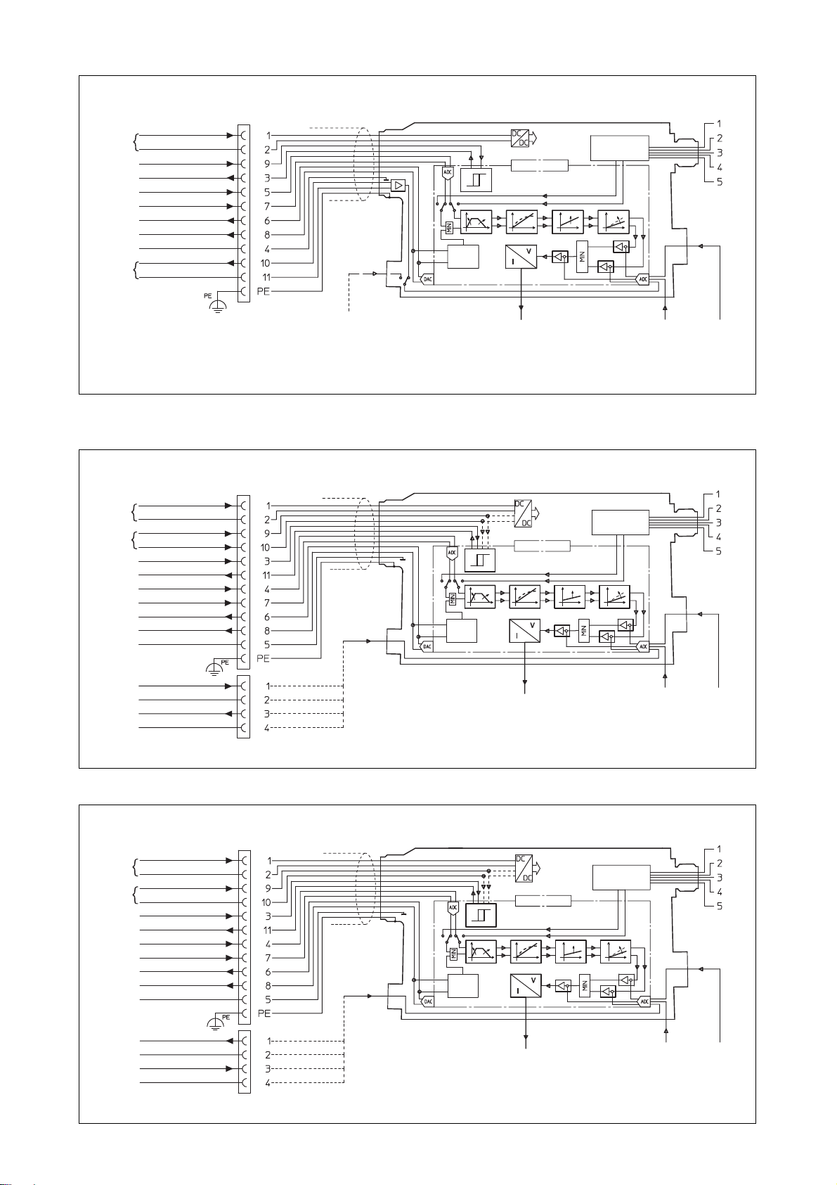
3.9 E-RI-PES Standard and option /X
3.10 E-RI-PES Option /S
3.11 E-RI-PES Option /Z
MICROCONTROLLER
PRESSURE VALUE
0 VDC
+ 24 VDC (power supply)
Reserved (do not connect)
RS232 OR
FIELDBUS
INTERFACE
Pressure
transducer
connection
+ 24 VDC (power stage)
0 V
DC (power stage)
+ 24 V
DC (logic stage)
0 VDC (logic stage)
ENABLE >9 to +24 V
DC
FAULT 0 or +24
VDC
FLOW INPUT SIGNAL
± 10 V
DC
PRESSURE INPUT
SIGNAL ± 10 V
DC
FLOW MONITOR
± 10 V
DC
PRESSURE
MONITOR ± 10 V
DC
SIGNAL ZERO
DC/DC
CONVERTER
FEEDBACK SWASH PLATE
FEEDBACK
COIL S1
FEEDBACK SWASH PLATE
FEEDBACK
HYDRAULIC
POWER
LIMITATOR
MICROCONTROLLER
RS232 OR
FIELDBUS
INTERFACE
DC/DC
CONVERTER
HYDRAULIC
POWER
LIMITATOR
MICROCONTROLLER
RS232 OR
FIELDBUS
INTERFACE
DC/DC
CONVERTER
FEEDBACK SWASH PLATE
FEEDBACK
HYDRAULIC
POWER
LIMITATOR
PRESSURE VALUE
0 VDC
+ 24 VDC (power supply)
Reserved (do not connect)
+ 24 VDC (power stage)
0 V
DC (power stage)
0 or +24
VDC (PID selection)
0 or +24
VDC (PID selection)
ENABLE >9 to
24
VDC
FAULT 0 or +24
VDC
FLOW INPUT SIGNAL
± 10 V
DC
PRESSURE INPUT
SIGNAL ± 10 V
DC
FLOW MONITOR
± 10 V
DC
PRESSURE
MONITOR ± 10 V
DC
SIGNAL ZERO
+ 24 V
DC (power supply)
0 V
DC (power supply)
POWER LIMITATION ENABLE
FAULT
FLOW INPUT
PRESSURE INPUT
FLOW MONITOR
PRESSURE MONITOR
SIGNAL ZERO
PRESSURE
FEEDBACK ± 10 V
DC
PRESSURE
FEEDBACK 0 V
DC
Pressure
transducer
connection
CABLE GLAND CONNECTION
FOR PRESSURE TRANSDUCER
OPTION /X
N.C. WITH
OPTION /X
POWER
SUPPLY
PID
SELECTION
POWER
SUPPLY
POWER
SUPPLY
POWER
SUPPLY
COIL S1
COIL S1
Page 45
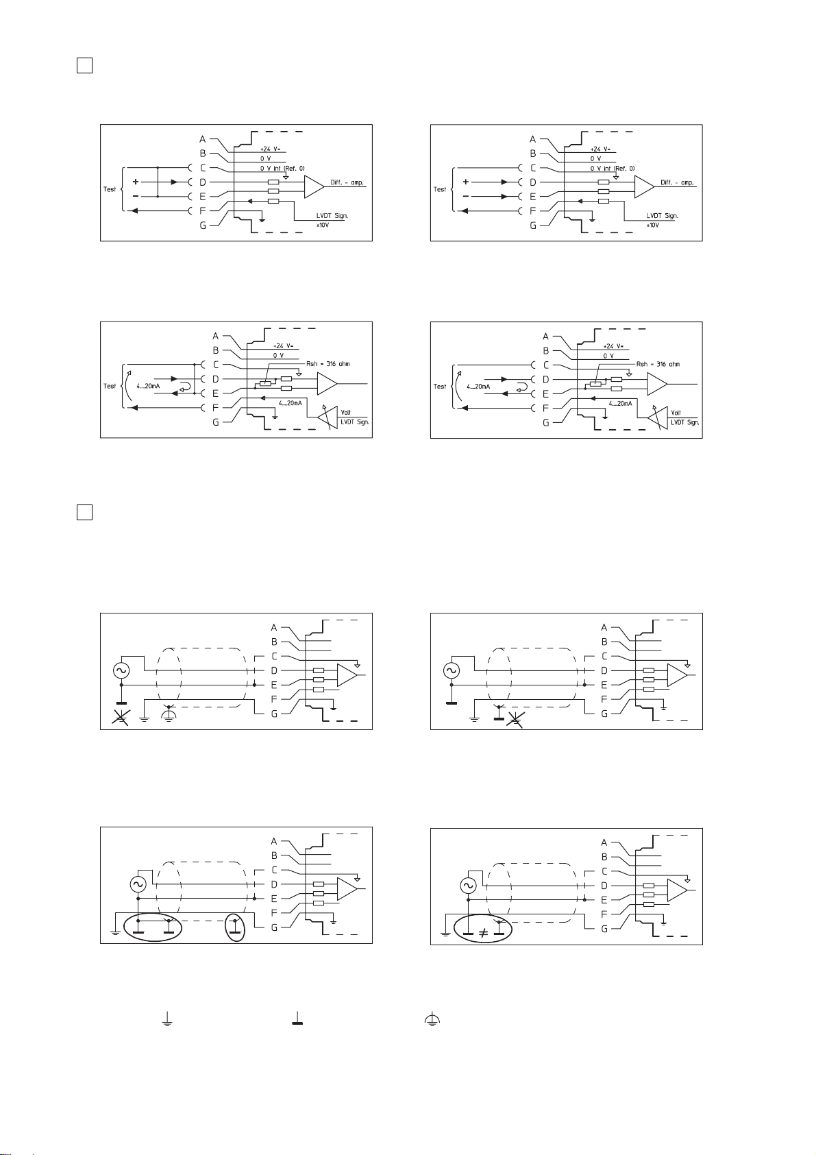
The connection of the command signal to the electronics is depending to the type of signal generated from the PLC or CNC.
The following figures show the typical connections in case of common zero or differential command situations.
COMMAND SIGNAL FOR OPTION /I
The correct shielding of signal cables has to be provided to protect the electronics from electrical noise disturbances, which could affect the valve functioning.
Examples of correct shielding criteria are shown in the following fig. E and F.
The shield connections of fig. G and H must be avoided because they could generate ground loops which enhance the noise effect.
Fig. A Power supply and signal common zero Fig. B Differential signals not connected with zero (floating)
Fig. C Common zero Fig. D Differential input signals
Fig. E Shield connected to the protected earth Fig. F Shield connected to the same power supply GND
Fig. G Never connect the shield on both sides Fig. H Never connect the shield to grounding facilities
having different potential
Symbols:
Standard earth
Supply GND Protected earth
CORRECT SHIELD CONNECTIONS
WRONG SHIELD CONNECTIONS
0 VDC
±10 VDC
0 VDC
MONITOR
0
VDC
MONITOR 4÷20mA
0 VDC
MONITOR 4÷20mA
0
VDC
MONITOR
4
COMMAND SIGNAL WIRING
5
SHIELD CONNECTIONS
Page 46
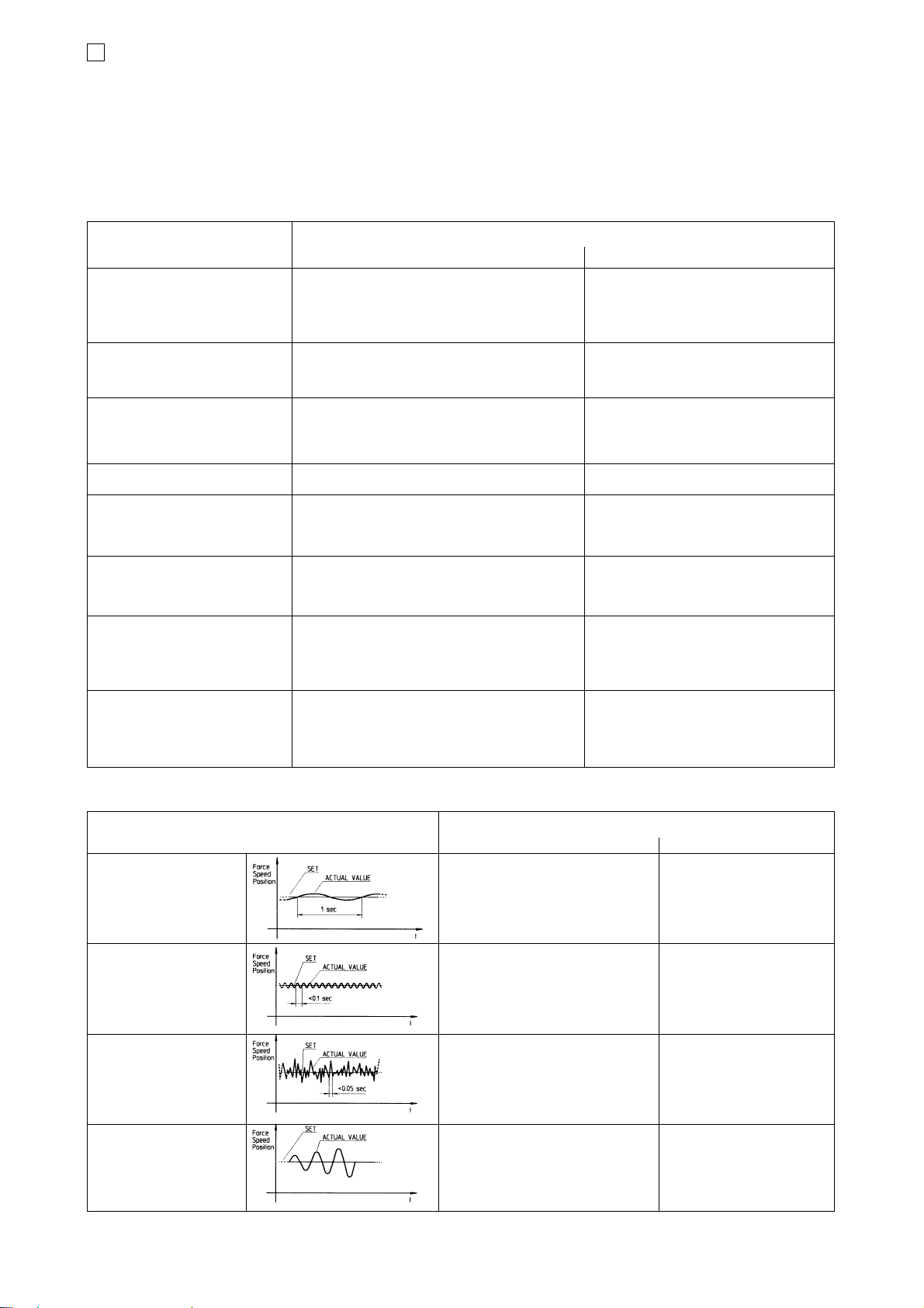
PROBLEMS CAUSES OF THE FAULTS
Mechanical/Hydraulic Electrical /Electronic
Unstable axes movement Defective pump
Pressure and/or flow fluctuations Air in the circuit Insufficient powered electrical supply
Fluid contaminated Noisy signals-bad grounding or shielding
Insufficient piloting pressure of double stage valves Electrical or electromagnetic disturbances
Stick-slip effect due to excessive friction of cylinder seals
Speed below minimum for hydraulic motors
Actuator overrun Hoses too elastic Bias current set too high
Remote controlled check valve not closing immediately Ramp time too long
Insufficient bleeding Limit switch overrun
Internal leakages Electrical switching time too slow
Standstill or not controllable axes Defective pump Cabling error
Proportional control valve blocked (dirt) Open circuit in electrical control leads
Hand valves and settings not in correct position Signalling devices incorrectly set or defectives
Lack of electrical power and/or reference signal
Transducers mechanically uncalibrated
Actuator running too slow Internal pump leaks due to wear Reference signal not correct
Flow control valve set too low Scale adjustment not correct
Insufficient output forces and torques Excessive resistance in the return and delivery lines Reference signal not correct
Operating pressure setting of control valves too low Scale adjustment not correct
Excessive pressure drop across control valves
Internal leaks of pump and valves due to wear
Line hammer during control operation Switching time of proportional control valves too rapid Ramp time too short or absent
Throttles or orifices damaged
No throttling before accumulator system
Excessive masses and forces applied to drive
Excessive operating temperature Insufficient lines cross section
Excessive continuous delivery
Pressure setting too high
Cooling system not operative
Zero pressure circulation inoperative during working
intervals
Excessive noise Filters blocked Dither adjustment not correct
Foaming of the fluid
Pump or motor mounting loose
Excessive resistance in the suction line
Proportional control valves buzz
Air in the valve solenoid
6
TROUBLE SHOOTING TABLES
6.1 Open loop applications
To evaluate the fault and to find the defective component within an electrohydraulic system it is necessary a good cooperation between electronic and
hydraulic engineers.
Besides a good knowledge of the technical tables for each component, for performing analysis of the system it is necessary to evaluate the hydraulic
scheme and the electric wiring diagram related to operation cycle.
There is no general recipe for succes in fault finding due to quite diverse nature of the electrohydraulic systems; however the following table provides a
useful start point.
Notes:
- Most problems are solved by the replacement of defective components on site. The defective components can be repaired by the manufacturer.
- Following tables don’t consider a system design fault
6.2 Closed loop applications - static conditions
CAUSES OF THE FAULTS
Mechanical/Hydraulic Electrical /Electronic
Low frequency oscillations Insufficient hydraulic power supply Axes card proportional and
Insufficient piloting pressure integral Gains set too low
Proportional valve defective Axes card
due to wear or dirt Sampling time too long
High frequency vibration Foaming of the fluid Axes card proportional Gain
Prop. valve defective due to wear or dirt set too high
Too high ∆ pressure across valve Electrical noises
Air in the solenoid of the
proportional valve
Short time peak (random) Mechanical couplings not rigid Driver’s bias current
in one direction or both Air in the solenoid of the proportional valve not correct
Proportional valve defective Electromagnetic disturbances
due to wear or dirt
Self amplificating oscillations Hydraulic hoses too elastic Axes card proportional and
Mechanical couplings not rigid integral Gains too high
Too high ∆ pressure across prop. valve
Too high hydraulic proportional valve gain
PROBLEMS
F003
Page 47
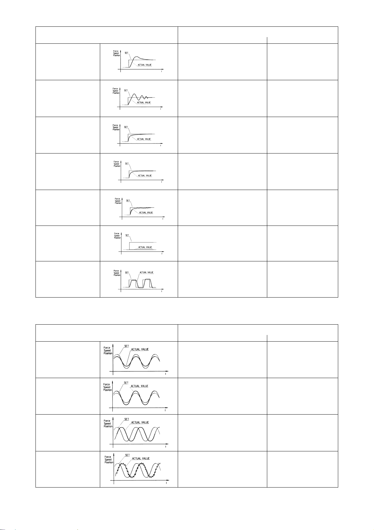
CAUSES OF THE FAULTS
Mechanical/Hydraulic Electrical /Electronic
Overshoot in one direction Too high ∆ pressure across valve Axes card Derivative
Gain set too low
Overshot in both directions Mechanical couplings not rigid Axes card Proportional
Hoses too elastic Gain set too high
Proportional control valve mounted Axes card Integral
too far from the actuators Gain set too low
Slow approach to set Pressure Gain of the proportional Axes card Proportional
control valve too low Gain set too low
Driver’s Bias current not correct
Drive unable to reach the set Insufficient hydraulic pressure or flow Axes card Integral Gain
set too high Proportional and
Derivate Gains set too low
Driver’s Scale and Bias
not correct
Unstable control Actuator’s feedback transducer Proportional Gain set too high
connection intermittent Integral Gain set too low
Hoses too elastic Electrical noises
Air in the solenoid of the proportional valve
to high friction
Inhibited control Actuator’s feedback transducer Lack of electrical power
mechanically uncalibrated
Lack of reference or feedback signal
Lack of hydraulic power Cabling error
Bad repeatability Actuator’s feedback transducer Axes card Proportional Gain
and high hysteresys connection intermittent set too high
Integral Gain set too low
6.3 Closed loop applications - dynamic conditions: step response
PROBLEMS
6.4 Closed loop applications - dynamic conditions: frequency response
CAUSES OF THE FAULTS
Mechanical/Hydraulic Electrical /Electronic
Amplitude damping Insufficient pressure and flow Axes card Proportional
Gain too low
Driver’s scale adjustments
set too low
Wave amplifier Hoses too elastic Driver’s scale adjustment
Proportional control valve not correct
too far from drive
Time delay Insufficient pressure and flow Ramp time inserted
Axes card derivative gain
set too low
Vibrating control Air in the solenoid of proportional valve Axes card proportional and
Derivative Gains too high
Electrical noises
Derivative Gain set too high
PROBLEMS
11/05
Page 48
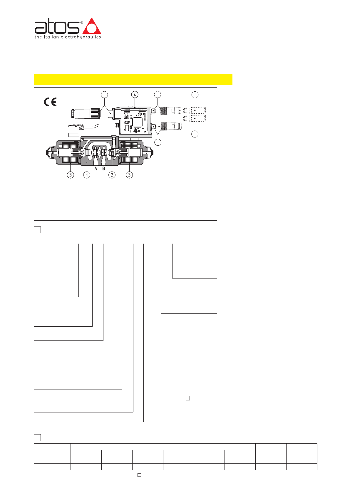
Series number
www.atos.com
Table F160-18/E
DHZO-A* and DKZOR-A* are proportional
valves, direct operated without position
transducer, which provide both directional
and non-compensated flow control
according to the electronic reference
signal.
They operate in association with electronic
drivers, see section
쪨
, which supply the
proportional valves with proper current to
align valve regulation to the reference
signal supplied to the electronic driver.
They are available in different executions:
• -A, without position transducer;
• -AE, -AES as -A plus analogue (AE) or
digital (AES) integral electronics
햵
;
The 4-way spool 햳, sliding into a
5-chambers body 햲, is directly operated
by proportional solenoids
햴
.
The integral electronics
햵
ensures factory
presetting, fine functionality plus valve-tovalve interchangeability and simplified
wiring and installation.
The electronic main connector 쩽 is fully
interchangeable for -AE and -AES
executions.
Standard 7 pin main connector is used for
power supply, analog input reference and
monitor signals.
12 pin connector is used for options /Z and
/W (AES).
Following communication interfaces 햷,
햸
are available for the digital -AES execution:
• -PS, Serial communication interface for
configuration, monitoring and firmware
updating through Atos PC software always present also for -BC, -BP and -EH
options.
• -BC, CANopen interface
•
-BP, PROFIBUS DP interface
•
-EH, EtherCAT interface
The valves with -BC, -BP and -EH
interfaces can be integrated into a fieldbus
communication network and thus digitally
operated by the machine control unit.
The coils are fully plastic encapsulated
with insulation class H.
Mounting surface: ISO 4401 sizes 06 and 10
Max flow respectively up to 50 l/min and
105 l/min with valve differential pressure
Δp = 30 bar, see table
쪩
.
Max pressure = 350 bar for DHZO;
315 bar for DKZOR.
DHZO
DHZO
size 06
DKZOR
size 10
A = without position
transducer
AE = as A plus integral
electronics
AES = as A plus inte-
gral digital electronics
Valve size - ISO 4401
0 = size 06 1 = size 10
Spool overlapping in central position, see sect.
쪩
1 = P, A, B, T positive overlapping (20% of spool
stroke)
3 = P positive overlapping; (20% of spool stroke)
A, B, T, negative overlapping
Spool size: 14, 1, 3, 5 = see section
쪩
AES PS
07 -1S5/ /***/*---
1
MODEL CODE
F160
DKZOR-AES-BC-171-*
Communication interfaces
only for AES (1)
PS = Serial
BC = CANopen
BP = PROFIBUS DP
EH = EtherCAT
Configuration, see section
쪩
5 = external plus central position, spring
centered
7 = 3 position, spring centered
Proportional directional valves type DHZO-AES and DKZOR-AES
direct operated, without position transducer, ISO 4401 size 06 and 10
Spool type (regulating characteristics)
L = linear; S = progressive;
D = differential-progressive
(as S, but with P-A= Q, P-B= Q/2)
Valve body
Spool
Proportional solenoid
Integral electronics
Main connector
햲
햳
햴
햵
햶
2
ELECTRONIC DRIVERS FOR DHZO-A*
Valve model
Data sheet
Drivers model E-MI-AC-0*F
G010
E-BM-AS-PS
G030
E-ME-AC-0*F
G035
-A
-AES
-AE
E-RP-AC-0*F
G100
E-RI-AE
G110
E-RI-AES
G115
Hydraulic options, see section 쪬:
B =solenoid and integral electronics
at side of port A
Y =external drain
Options for -A execution see sect. 쪭:
MO = horizontal hand lever
MV = vertical hand lever
BMO = horizontal hand lever instal-
led at side of port A
BMV = vertical hand lever installed
at side of port A
N = manual micrometric adjustment
NV = as N plus handwheel and gra-
duated scale
Electronics options for -AE execution see section
쪯
:
I =
current reference input (4÷20 mA)
Q=enable signal
Electronics options for -AES exe-
cution see section :
Q = enable signal
Z = double power supply, enable fault
and monitor (12 pin connector)
W =power limitation function (12 pin
connector) see section 11.3
11
-BC or -BP communication connector
-PS communication connector (3)
-EH Communication connector (input)
-EH Communication connector (output)
햷
햸
햹
햺
Note: (1) Serial communication interface always present, also for -BC, -BP and -EH options
Note: For power supply and communication connector see section 14
E-BM-AC-0*F
G025
E-MI-AS-IR
G020
*
Coil voltage (only for -A execution) see section 쪭:
- = standard coil for 24V
DC
Atos drivers
6 = optional coil for 12VDCAtos
drivers
18 = optional coil for low cur-
rent drivers
Seals material,
see section 쪪:
- =
NBR
PE = FKM
BT = HNBR
(only -A)
AES execution included in this table is available only for running supplies or spare parts
For new applications it is suggested new AEB and AES executions, see table FS160
5
6
8
9
7
Page 49
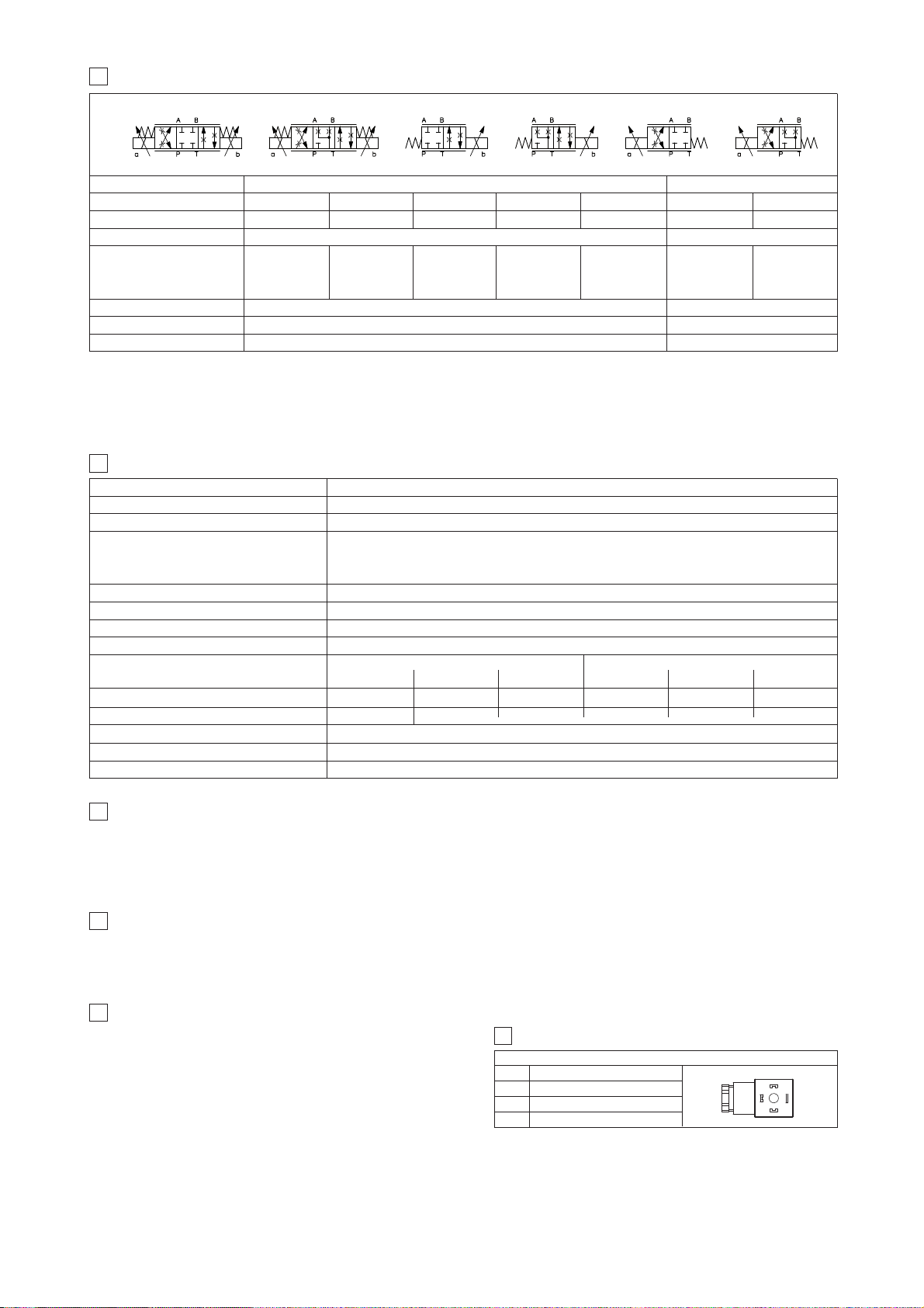
3
HYDRAULIC CHARACTERISTICS (based on mineral oil ISO VG 46 at 50 °C)
Valve model
DHZO
Spool type and size
Spool overlapping
Max flow (1) [l/min]
at
Δ
p = 10 bar (P-T)
at
Δ
p = 30 bar (P-T)
at
Δ
p = 70 bar (P-T)
Response time (2) [ms]
Hysteresis [%]
Repeatability
< 30
≤ 5%
± 1%
< 40
≤ 5%
± 1%
1
2
3
4,5
8
12
45
80
120
60
105
160
L14 L1
17
30
45
S3, L3, D3
28
50
74
S5, L5, D5 S3, L3, D3 S5, L5, D5
1, 3 1, 3 1, 3 1, 3 1, 3 1, 3
Hydraulic symbols
*71, *71/B *73, *73/B *51 *53 *51/B *53/B
b b b a a
a
a b
Notes:
앬
Above performance data refer to valves coupled with Atos electronic drivers, see section 쪨.
앬
The flow regulated by the directional proportional valves is not pressure compensated, thus it is affected by the load variations.To keep costant the
regulated flow under different load conditions, modular pressure compensators are available (see tab. D150).
(1) For different
Δ
p, the max flow is in accordance to the diagrams in sections 14.2 and 15.2
(2) 0-100% step signal
DKZOR
Pressure limits [bar] ports P, A, B = 350; T = 210 (250 with external drain /Y)
8
14
21
S2
1, 3
ports P, A, B = 315; T = 210 (250 /Y)
4
MAIN CHARACTERISTICS
6
HYDRAULIC OPTIONS
6.1 Option /B Solenoid (for valve configuration *5*), and integral electronics at side of port A. For hydraulic configuration vs. reference signal, see
section 14.1 and 15.1
6.2 Option /Y External drain advisable when the valve is used in double flow path, see section 14.5 and 15.5. Option /Y is mandatary if the pressure in
port T exceeds 160 bar.
DHZO and DKZOR proportional valves are CE marked according to the applicable Directives (e.g. Immunity/Emission EMC Directive and Low Voltage Directive).
Installation, wirings and start-up procedures must be performed according to the general prescriptions shown in table F003 and in the installation notes
supplied with relevant components.
The electrical signals of the valve (e.g. monitor signals) must not be directly used to activate safety functions, like to switch-ON/OFF the machine’s safety
components, as prescribed by the European standards (Safety requirements of fluid technology systems and components-hydraulics, EN-982).
5
GENERAL NOTES
8
CONNECTIONS FOR -A EXECUTION
Signal description
SUPPLY
SUPPLY
GND
PIN
1
2
3
SOLENOID POWER SUPPLY CONNECTOR
1
2
3
7
OPTIONS FOR -A EXECUTION
7.1 Option /6
optional coil to be used with Atos drivers with power supply 12 VDC
7.2 Option /18
optional coil to be used with electronic drivers not supplied by Atos
7.3 Auxiliary hand lever
this option is available only for DHZO-A with spool type S3, S5, D3, D5, L3, L5.
It allows to operate the valve in absence of electrical power supply. For detailed description of DHZO-A with hand lever option see table E138
앬
Option /MO horizontal hand lever
앬
Option /MV vertical hand lever
앬
Option /BMO horizontal hand lever installed at side of port A
앬
Option /BMV vertical hand lever installed at side of port A
The following supplementary options allow to operate the valve in absence of
electrical power supply by means of a micrometric screw replacing the standard solenoid manual override, see table TK500
7.4 Option /N manual micrometric adjustment
7.5 Option /NV as /N plus handwheel and graduated scale
Assembly position Any position
Subplate surface finishing Roughness index, Ra 0,4 flatness ratio 0,01/100 (ISO 1101)
MTTFd valves according to EN ISO 13849 150 years, for further details, see technical table P004
-A execution = -20°C ÷ +70°C (storage -20°C ÷ +80°C) /BT option -40°C ÷ +60°C (storage -20°C ÷ +70°C)
Ambient temperature -AE execution = -20°C ÷ +60°C (storage -20°C ÷ +70°C)
-AES execution = -20°C ÷ +60°C (storage -20°C ÷ +70°C)
Fluid Hydraulic mineral oil HL, HLP as per DIN 51524
Recommended viscosity 20÷100 mm
2
/s - max allowed range 15 ÷ 380 mm2/s
Fluid contamination class ISO 4406 class 20/18/15 NAS 1638 class 9, in line filters of 10 μm (β10 _>75 recommended)
Fluid temperature -20°C +60°C (standard seals) -20°C +80°C (/PE option) -40°C +60°C (/BT option)
Coil code DHZO-A* DKZOR-A*
Coil resistance R at 20°C 3 ÷ 3,3
Ω
2 ÷ 2,2
Ω
13 ÷ 13,4
Ω
3,8 ÷ 4,1
Ω
2,2 ÷ 2,4
Ω
12 ÷ 12,5
Ω
Max. solenoid current 2,2 A 2,75 A 1 A 2,6 A 3,25 A 1,2 A
Max. power
30 Watt for DHZO-A execution; 35 Watt for DKZOR-A execution; 50 Watt for -AE and -AES executions
Protection degree (CEI EN-60529)
IP65 for -A execution; IP67 for -AE and -AES, executions
Duty factor Continuous rating (ED=100%)
standard option /6 option /18 standard option /6 option /18
Page 50
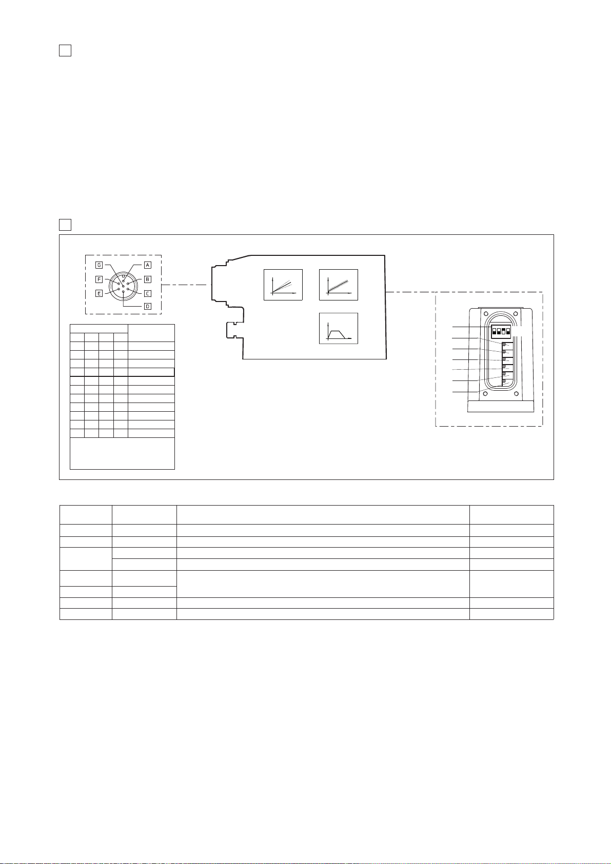
9 ANALOG INTEGRAL DRIVERS -AE - OPTIONS
Standard driver execution provides on the 7 pin main connector:
Power supply
- 24VDC must be appropriately stabilized or rectified and filtered; a 2,5 A safety fuse is required in series to the driver power supply.
Apply at least a 10000 μF/40 V capacitance to single phase rectifiers or a 4700 μF/40 V capacitance to three phase rectifiers
Reference input signal
- analog differential input with ±10 VDC nominal range (pin D, E), proportional to desired coil current
Monitor output signal
- analog output signal proportional to the actual valve’s coil current (1V monitor = 1A coil current)
Following options are available to adapt standard execution to special application requirements:
9.1 Option /I
It provides the 4÷20 mA current reference signal instead of the standard ±10 V
DC. Monitor output signal is still the standard ±10 VDC
It is normally used in case of long distance between the machine control unit and the valve or where the reference signal can be affected by electrical
noise; the valve functioning is disabled in case of reference signal cable breakage.
9.2 Option /Q
It provides the possibility to enable or disable the valve functioning without cutting the power supply (the valve functioning is disabled but the driver current output stage is still active). To enable the driver supply a 24V
DC on the enable input signal.
9.2 Possible combined option: /IQ
CURRENT
TO COIL S2
REGULATIONS AND SWITCHES
7 PIN - STANDARD
MAIN CONNECTOR
BIAS
SCALE
RAMPS
B2
B1
S2
S1
positive bias adjust
쩨
쩨
쩨
쩨
쩨
(driver view)
negative bias adjust (only for double solenoid valves)
positive scale adjust
negative scale adjust (only for double solenoid valves)
B1:
B2:
S1:
S2:
(remove the rear cover)
SW
10 ANALOG INTEGRAL DRIVERS -AE - MAIN FUNCTIONS AND ELECTRONIC CONNECTIONS
Selector SW
Dither frequency
[Hz]
SW1 SW2 SW3 SW4
ON
ON
ON
ON ON
ON ON
ON ON ON
ON ON ON
ON ON ON
ON ON ON
ON ON ON ON
The dither frequency is factory preset at 200 Hz and its regulation may
be adjusted after contact with Atos
technical department
100
130
160
200 (Standard)
230
270
300
380
430
470
500
(only for double
solenoid valves)
쩨
쩨
RU
RD
ramp for increasing reference signal
ramp for decreasing reference signal
RU:
RD:
dither frequency selector (see table beside)
SW:
ON
OFF
PIN SIGNAL
TECHNICAL SPECIFICATIONS
NOTES
A V+ Power supply 24 VDC for solenoid power stage and driver logic Input - power supply
B V0 Power supply 0 VDC for solenoid power stage and driver logic Gnd - power supply
C
(1)
AGND Ground - signal zero for MONITOR signal Gnd - analog signal
ENABLE Enable (24 VDC) or disable (0 VDC) the driver (for /Q option) Input - on/off signal
D INPUT+
Reference analog differential input: ±10 VDC maximum range (4 ÷ 20 mA for /I option)
Default setting for single solenoid valves: 0÷+10 V
DC
Default setting for double solenoid valves: ±10 VDC
Input - analog signal
E INPUT -
F MONITOR
Monitor analog output: ±5 VDCmaximum range; 1 V = 1 A
Output - analog signal
G EARTH Internally connected to the driver housing
Note: (1) with /Q option ENABLE signal replaces AGND on pin C; MONITOR signal is referred to pin B.
A minimum time of 60ms to 160ms have be considered between the driver energizing with the 24 VDC power supply and when the valve is ready
to operate. During this time the current to the valve coils is switched to zero
10.1 7 PIN MAIN CONNECTOR
Page 51
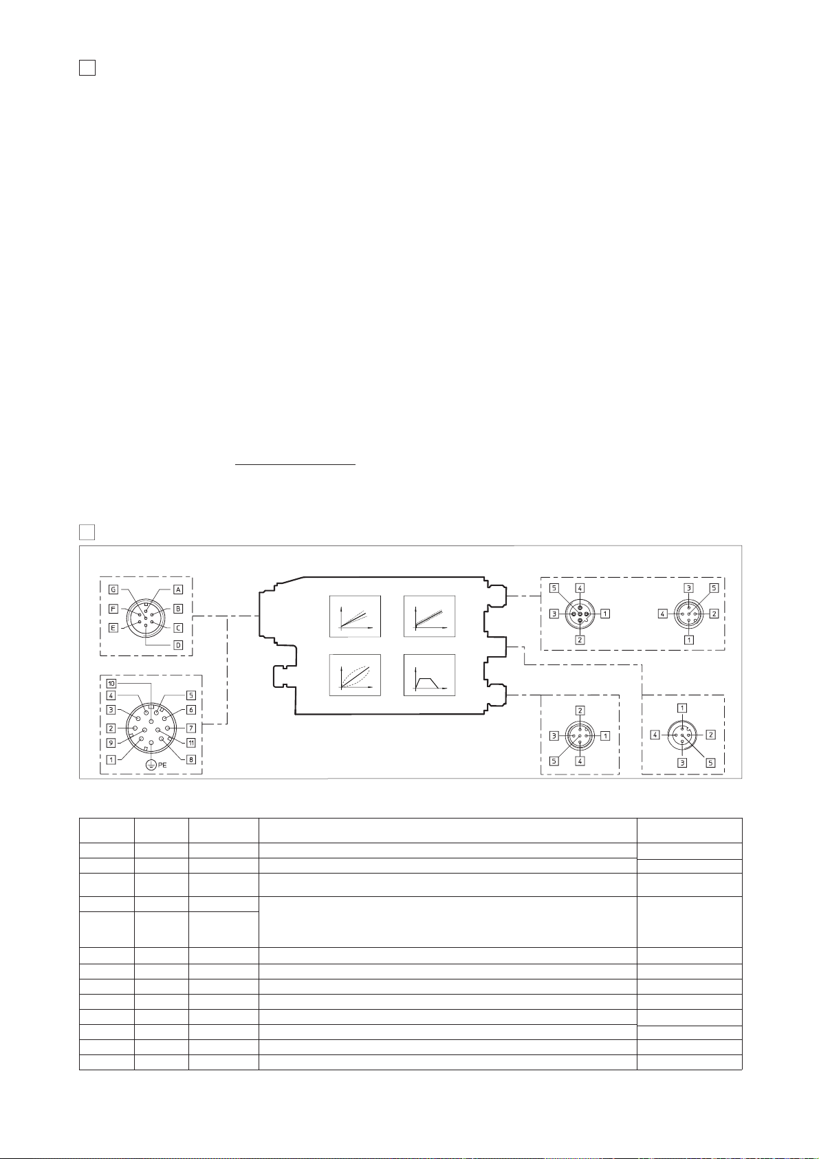
11 DIGITAL INTEGRAL DRIVERS -AES - OPTIONS
Standard driver execution provides on the 7 pin main connector:
Power supply
- 24VDC must be appropriately stabilized or rectified and filtered; a 2,5 A safety fuse is required in series to each driver power supply
Apply at least a 10000 μF/40 V capacitance to single phase rectifiers or a 4700 μF/40 V capacitance to three phase rectifiers.
Reference input signal
- analog differential input with ±10VDC nominal range (pin D,E), proportional to desired coil current (4÷20 mA with cable
break detection, ±10 mA, ±20 mA or 0÷20 mA software selectable)
Monitor output signal
- analog output signal proportional to the actual valve’s coil current (1V monitor = 1A coil current)
Following options are available to adapt standard execution to special application requirements:
11.1 Option /Q
To enable the driver, supply 24Vdc on pin C referred to pin B: when the enable signal is set to zero the valve status is software selectable, by factory
default the valve functioning is disabled (zero current to the solenoid) but the driver current output stage is still active. For the complete list of selectable
status, see tab. G115.
11.2 Option /Z
It provides, on the 12 pin main connector, the following additional features:
Logic power supply
Separated power supply for the solenoid (pin 1, 2) and for the digital electronic circuits (pin 9, 10).
Cutting solenoid power supply allows to interrupt the valve functioning but keeping energized the digital electronics thus avoiding fault conditions of the
machine fieldbus controller. This condition allows to realize safety systems in compliance with European Norms EN13849-1 (ex EN954-1).
Enable Input Signal
To enable the driver, supply 24Vdc on pin 3 referred to pin 2: when the enable signal is set to zero the valve status is software selectable, by factory
default the valve functioning is disabled (zero current to the solenoid) but the driver current output stage is still active. For the complete list of selectable
status, see tab. G115.
Fault Output Signal
Fault output signal indicates fault conditions of the driver (solenoid short circuits/not connected, reference signal cable broken for 4÷20mA input, etc.).
Fault presence corresponds to 0
VDC
, normal working corresponds to 24
VDC (pin 11 referred to pin 2)
: Fault status is not affected by the Enable input signal
11.3 Option /W - only for valves coupled with pressure compensator type HC-011 or KC-011 (see tab. D150).
It provides, on the 12 pin main connector, the above option /Z features plus the hydraulic power limitation function.
The driver receives the flow reference signal by the analog external input INPUT+ and a pressure transducer remotely installed in the hydraulic system,
has to be connected to the driver’s analog input TR.
When the actual requested hydraulic power pxQ (TR x INPUT+) reaches the max power limit (p1xQ1), internally set by software, the driver automatically
reduces the flow regulation of the valve. The higher is the pressure feedback the lower is the valve’s regulated flow:
Flow regulation = Min
(
PowerLimit [sw setting]
; Flow Reference [INPUT+]
)
Transducer Pressure [TR]
For detailed information on hydraulic power limitation, see tab. G115
F160
12 DIGITAL INTEGRAL DRIVERS -AES - MAIN FUNCTIONS AND ELECTRONIC CONNECTIONS
COMMUNICATION CONNECTOR
12 PIN - OPTION /Z and /W
7 PIN - STANDARD
5 PIN
Serial (-PS)
5 PIN
Pressure
connection (/W)
5 PIN
PROFIBUS (-BP)
5 PIN
CANopen (-BC)
RAMPS
BIASSCALE
MAIN CONNECTOR
(driver view)
(driver view)
CURRENT
TO COIL S2
(for double
solenoid valves)
(driver view)
LINEARIZATION
(driver view)
(driver view)
For electronic connections of digital drivers
AEG and controllers AEZ, see tab. G120
12.1 7 or 12 PIN MAIN CONNECTOR (-AES standard, /Q, /Z, /W options)
Standard
7pin
/Z, /W options
12pin
SIGNAL TECHNICAL SPECIFICATIONS NOTES
A 1 V+
Power supply 24 VDC for solenoid power stage (and for driver logic on 7 pin connection)
Input - power supply
Gnd - power supply
B 2 V0 Power supply 0 VDC for solenoid power stage
(and for driver logic on 7 pin connection)
C
(option /Q)
3 ENABLE Enable (24 VDC) or disable (0 VDC) the driver Input - on/off signal
D 4 INPUT+
Reference analog input: ±10 VDC / ±20 mA maximum range software selectable
Default setting for single solenoid valves: 0÷+10 V
DC, differential input
Default setting for double solenoid valves: ±10 V
DC, differential input
/Z and /W options: common mode INPUT+ referred to AGND
Input - analog signal
E - INPUT -
C 5 AGND Ground - signal zero for MONITOR signal (INPUT+ signal only for /Z and /W options) Gnd - analog signal
F 6 MONITOR Monitor analog output: ±5 VDC maximum range; Default setting 1V = 1A Output - analog signal
- 7 NC do not connect
- 8 MONITOR 2
2nd monitor analog output: ±5 VDC maximum range (only for /W option)
Output - analog signal
- 9 VL+ Power supply 24 VDC for driver logic
Input - power supply
Gnd - power supply
- 10 VL0 Power supply 0 VDC for driver logic
- 11 FAULT Fault (0 VDC) or normal working (24 VDC) Output - on/off signal
G PE EARTH Internally connected to the driver housing
Note: A minimum time of 270 to 340 ms have be considered between the driver energizing with the 24 VDC power supply and when the valve is ready to operate.
During this time the current to the valve coils is switched to zero.
Page 52
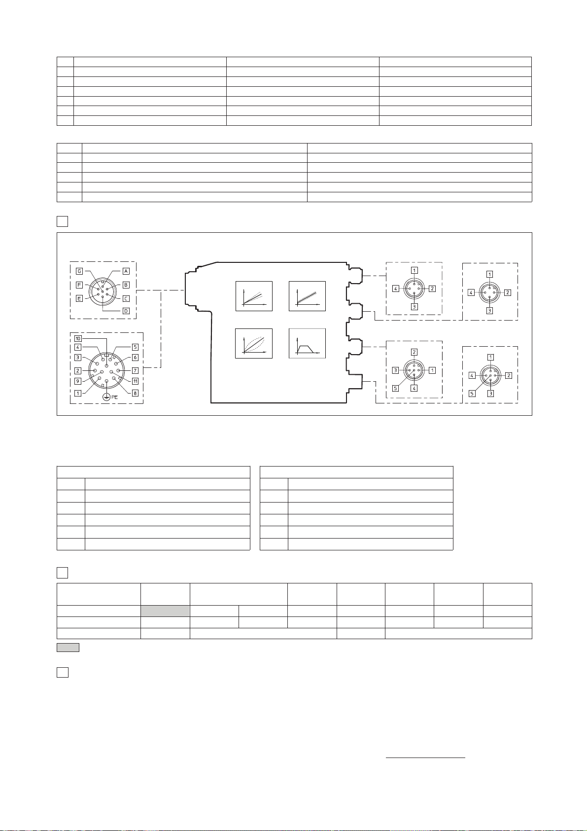
15
SOFTWARE TOOLS
The driver configuration and parameters can be easily set with the Atos E-SW programming software, available in four different versions according to the
driver’s communication execution: E-SW-PS (Serial), E-SW-BC (CANopen), E-SW-BP (PROFIBUS DP), E-SW-EH (EtherCAT). Programming software
E-SW-BC, E-SW-BP, E-SW-EH for BC, BP and -EH drivers, can be also used to modify the valve’s parameterization through the serial communication interface, without disconnecting the valve from the machine’s bus line.
For a more detailed description of software interface, PC requirements, adapters, cables and terminators, please refer to technical table G500.
Programming software, must be ordered separately:
E-SW-* (mandatory - first supply) = Dvd including E-SW-* software installer and operator manuals; it allows the registration to Atos digital service
E-SW-*-N (optional - next supplies) = as above but not allowing the registration to Atos digital service
On first supply of the E-SW-* software, it is required to apply for the registration in the Atos download area: www.download.atos.com.
Once the registration is completed, the password will be sent by email.
The software remains active for 10 days from the installation date and then it stops until the user inputs his password.
With the password you can also download, in your personal area, the latest releases of the Atos software, manuals, drivers and configuration files.
COMMUNICATION CONNECTOR
12 PIN - OPTION /Z and /W
7 PIN - STANDARD
RAMPS
BIASSCALE
MAIN CONNECTOR
(driver side)
(driver side)
LINEARIZATION
(driver side)
5 PIN
Serial (-PS)
4 PIN (input)
EtherCAT (-EH)
(driver side)
4 PIN (output)
EtherCAT (-EH)
(driver side)
DIGITAL INTEGRAL DRIVER -AES-EH - MAIN FUNCTIONS AND ELECTRONIC CONNECTIONS
13
13.1 4 & 5 PIN M12 COMMUNICATION CONNECTORS
EtherCAT (-EH)
PIN SIGNAL TECHNICAL SPECIFICATION
1 TX+ Transmitter
2 RX+ Receiver
3 TX- Transmitter
4 RX- Receiver
Housing Shield Positioned on control cabinet side
Serial (-PS)
PIN SIGNAL TECHNICAL SPECIFICATION
1 NC do not connect
2 NC do not connect
3 RS_GND Signal zero data line
4 RS_RX Valves receiving data line
5 RS_TX Valves transmitting data line
5 PIN
Pressure
connection (/W)
(driver side)
12.2 ELECTRONIC CONNECTIONS - 5 PIN COMMUNICATION AND PRESSURE TRANSDUCER CONNECTORS
Serial (-PS) CANopen (-BC) PROFIBUS DP (-BP)
PIN SIGNAL TECHNICAL SPECIFICATION SIGNAL TECHNICAL SPECIFICATION SIGNAL TECHNICAL SPECIFICATION
1 NC do not connect CAN_SHLD Shield +5V for termination
2 NC do not connect NC do not connect LINE-A Bus line (high)
3 RS_GND Signal zero data line CAN_GND Signal zero data line DGND data line and termination Signal zero
4 RS_RX Valves receiving data line CAN_H Bus line (high) LINE-B Bus line (low)
5 RS_TX Valves transmitting data line CAN_L Bus line (low) SHIELD do not connect
PIN Input Voltage (Software selectable) Input Current (Software selectable)
1 VT Remote transducer power supply 24 VDC VT Remote transducer power supply 24 VDC
2 TR Remote transducer signal (0 ÷ 10 VDC) TR Remote transducer signal (0 ÷ 20 mA)
3 AGND signal zero for power supply and signal NC do not connect
4 NC do not connect NC do not connect
5 NC do not connect NC do not connect
12.3 5 PIN M12 PRESSURE CONNECTOR (only for /W option)
Note: for the electronic connections of 7 or 12 pin main connector, see section 12.1
for pressure transducer electronic connector (option /W) see section 12.3)
MODEL CODES OF POWER SUPPLY AND COMMUNICATION CONNECTORS (to be ordered separately)
14
666
connectors supplyed with the valve
VALVE VERSION
CONNECTOR CODE
ZH-7P ZM-7P ZH-12P ZH-5P ZH-5P/BP ZM-4PM/EH
PROTECTION DEGREE
IP65 IP67 IP67 IP67 IP67 IP67
-A -AE, -AES -AES/Z
-Serial (-PS)
or
CANopen (-BC)
PROFIBUS DP
(-BP)
IP67
EtherCAT (-EH)
DATA SHEET
K500 G110, G115, K500
G115, K500
ZH-5PM
IP67
-AES/W
-AEZ
G115, K500
Page 53
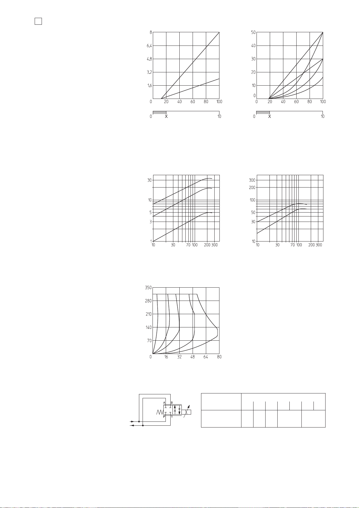
Max flow Δp= 70bar
[l/min]
20 80 100
SPOOL TYPE
L1 L3 S3 L5 S5
40
S2
6
L14
16
DIAGRAMS FOR DHZO (based on mineral oil ISO VG 46 at 50 °C)
5.1 Regulation diagrams
1 = linear spool L14
2 = linear spool L1
3 = progressive spool S2
4 = linear spool L3
5 = progressive spool S3, D3
6 = linear spool L5
7 = progressive spool S5, D5
16.2 Flow /
Δ
p diagrams
stated at 100% of valve stroke
1 = spool L14
2 = spool L1
3 = spool S2
4 = spool S3, L3, D3
5 = spool S5, L5, D5
F160
Max flow [l/min] at
Δ
p = 30 bar
Max flow [l/min] at
Δ
p = 30 bar
Stroke [% of max] Stroke [% of max]
Reference signal [V]
X = Threshold for bias activation depending to the valve type and amplifier type
Reference signal [V]
2
5
6
3
4
16.4 Operation as throttle valve
Single solenoid valves (DHZO-*-051)
can be used as simple throttle valves:
Pmax = 250 bar (option /Y advisable)
Flow rate [l/min]
Valve pressure drop Δp [bar]
2
1
Valve pressure drop Δp [bar]
4
5
Note: hydraulic configuration vs reference signal for
double solenoid valves (standard and option /B)
Reference signal 0 ÷ +10 V
P 촞 A / B 촞 T
12 ÷ 20 mA
Reference signal 0 ÷ -10 V
P 촞 B / A 촞 T
4 ÷ 12 mA
Hydraulic configuration vs reference signal
for single solenoid valves:
Reference signal:
0 ÷ +10 V P 촞 A / B 촞 T (standard)
4 ÷ 20 mA P 촞 B / A 촞 T (option /B)
1
7
3
}
}
}
Valve pressure drop Δp [bar]
Flow rate [l/min]
16.3 Operating limits
1 = spool L14
2 = spool L1
3 = spool S2
4 = spool L3, S3, D3
5 = spool L5, S5, D5
2
1
435
Flow rate [l/min]
Page 54
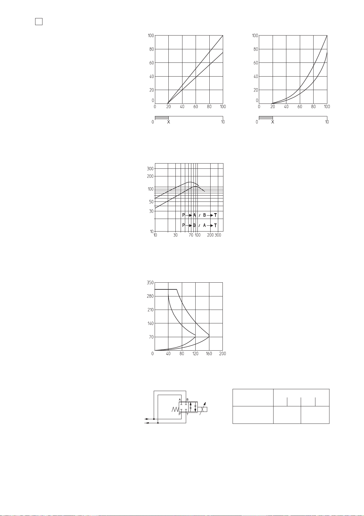
17
DIAGRAMS FOR DKZOR (based on mineral oil ISO VG 46 at 50 °C)
Max flow [l/min] at
Δ
P = 30 bar
Max flow [l/min] at
Δ
P = 30 bar
Stroke [% of max] Stroke [% of max]
1
2
4
3
17.4 Operation as throttle valve
Single solenoid valves (DKZOR-*-151)
can be used as simple throttle valves:
Pmax = 250 bar (option /Y advisable)
100 160
SPOOL TYPE
L3 S3 S5
Flow rate [l/min]Valve pressure drop
Δ
P [bar]
Flow rate [l/min]
1
2
2
1
17.1 Regulation diagrams
1 = linear spool L3
2 = progressive spool S3, D3
3 = linear spool L5
4 = progressive spool S5, D5
17.2 Flow /Δp diagrams
stated at 100% of valve stroke
1 = spool S3, L3, D3
2 = spool S5, L5, D5
17.3 Operating limits
1 = spool L3, S3, D3
2 = spool L5, S5, D5
Reference signal [V]
X = Threshold for bias activation depending to the valve type and amplifier type
Reference signal [V]
L5
Max flow Δp= 30 bar
[l/min]
Note:
Hydraulic configuration vs reference signal for
double solenoid valves (standard and option /B)
Reference signal 0 ÷ +10 V
P 촞 A / B 촞 T
12 ÷ 20 mA
Reference signal 0 ÷ -10 V
P 촞 B / A 촞 T
4 ÷ 12 mA
Hydraulic configuration vs reference signal
for single solenoid valves:
Reference signal:
0 ÷ +10 V P 촞 A / B 촞 T (standard)
4 ÷ 20 mA P 촞 B / A 촞 T (option /B)
}
}
}
Valve pressure drop Δp [bar]
Page 55
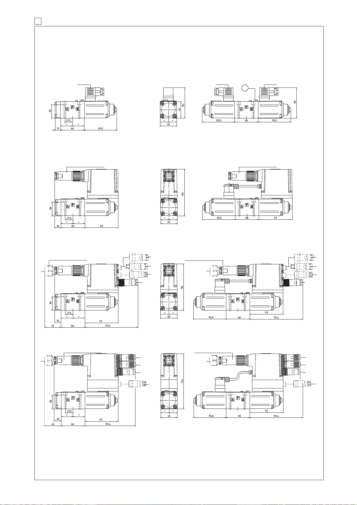
18 INSTALLATION DIMENSIONS FOR DHZO [mm]
Mass: 3,1 kg
Mass: 3,1 kgMass: 2,3 kg
Mass: 2,3 kg
Mass: 1,9 kg
DHZO-A-05
DHZO-AES-05 DHZO-AES-07
DHZO-AE-05 DHZO-AE-07
ISO 4401: 2005
Mou
nting surface: 4401-03-02-0-05
(see table P005)
(for /Y version, surface 4401-03-03-0-05 without X port)
Fastening bolts: 4 socket head screws M5x50 class 12.9
Tightening torque = 8 Nm
Seals: 4 OR 108; 1 OR 2025
Diameter of ports A, B, P, T: Ø 7,5 mm (max)
Diameter of port Y: Ø = 3,2 mm (only for /Y option)
Note: for option /B the solenoid is at side of port A
Mass: 2,6 kg
V
F160
666
666
666
ZH-7P or ZM-7P
ZH-7P or ZM-7P
쩸
ZH-7P or ZM-7P
ZH-7P or ZM-7P
쩸
훾
훽
훿
훾
훽
훿
DHZO-A-07
Mass: 3,2 kg
Mass: 2,4 kg
DHZO-AES-EH-05 DHZO-AES-EH-07
쩸
ZH-7P or ZM-7P
ZH-7P or ZM-7P
쩸
훽
쩸
dotted line = 12 pin connector ZH-12P for option /Z, /W
-BP communication interface, ZH-5P/BP connector
-BC communication interface, ZH-5P connector
-PS communication interface, ZH-5P connector
훿
훾
-Option /W pressure transducer interface, ZH-5PM connector
-EH communication interface (input), ZM-4PM/EH connector
훽
-EH communication interface (output), ZM-4PM/EH connector
훽
Page 56
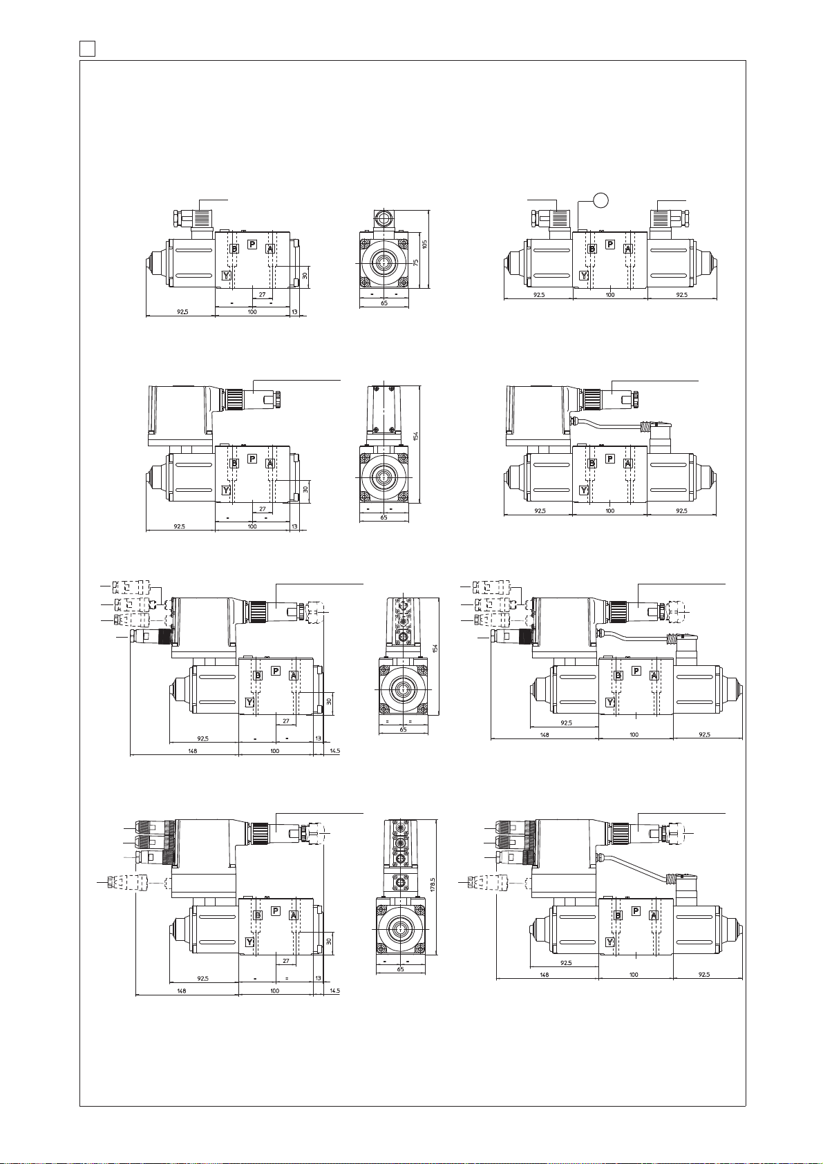
19 INSTALLATION DIMENSIONS FOR DKZOR [mm]
ISO 4401: 2005
Mou
nting surface: 4401-05-04-0-05
(see table P005)
(for /Y version, surface 4401-05-05-0-05 without X port)
Fastening bolts: 4 socket head screws M6x40 class 12.9
Tightening torque = 15 Nm
Seals: 5 OR 2050; 1 OR 108
Diameter of ports A, B, P, T: Ø 11,2 mm (max)
Diameter of port Y: Ø = 5 mm (only for /Y option)
03/15
Mass: 5,0 kg
Mass: 5,0 kgMass: 4,3 kg
Mass: 4,3 kg
Mass: 3,8 kg
DKZOR-A-15
DKZOR-AES-15 DKZOR-AES-17
DKZOR-A-17
DKZOR-AE-15 DKZOR-AE-17
Mass: 4,5 kg
Note: for option /B the solenoid is at side of port A
V
666
666
666
ZH-7P or ZM-7P
ZH-7P or ZM-7P
쩸
ZH-7P or ZM-7P
쩸
ZH-7P or ZM-7P
훾
훽
훿
훽
훿
Mass: 5,1 kgMass: 4,4 kg
DKZOR-AES-EH-15 DKZOR-AES-EH-17
쩸
ZH-7P or ZM-7P
쩸
ZH-7P or ZM-7P
훽
훽
쩸
dotted line = 12 pin connector ZH-12P for option /Z, /W
-BP communication interface, ZH-5P/BP connector
-BC communication interface, ZH-5P connector
-PS communication interface, ZH-5P connector
훿
훾
-Option /W pressure transducer interface, ZH-5PM connector
-EH communication interface (input), ZM-4PM/EH connector
훽
-EH communication interface (output), ZM-4PM/EH connector
Page 57

Page 58
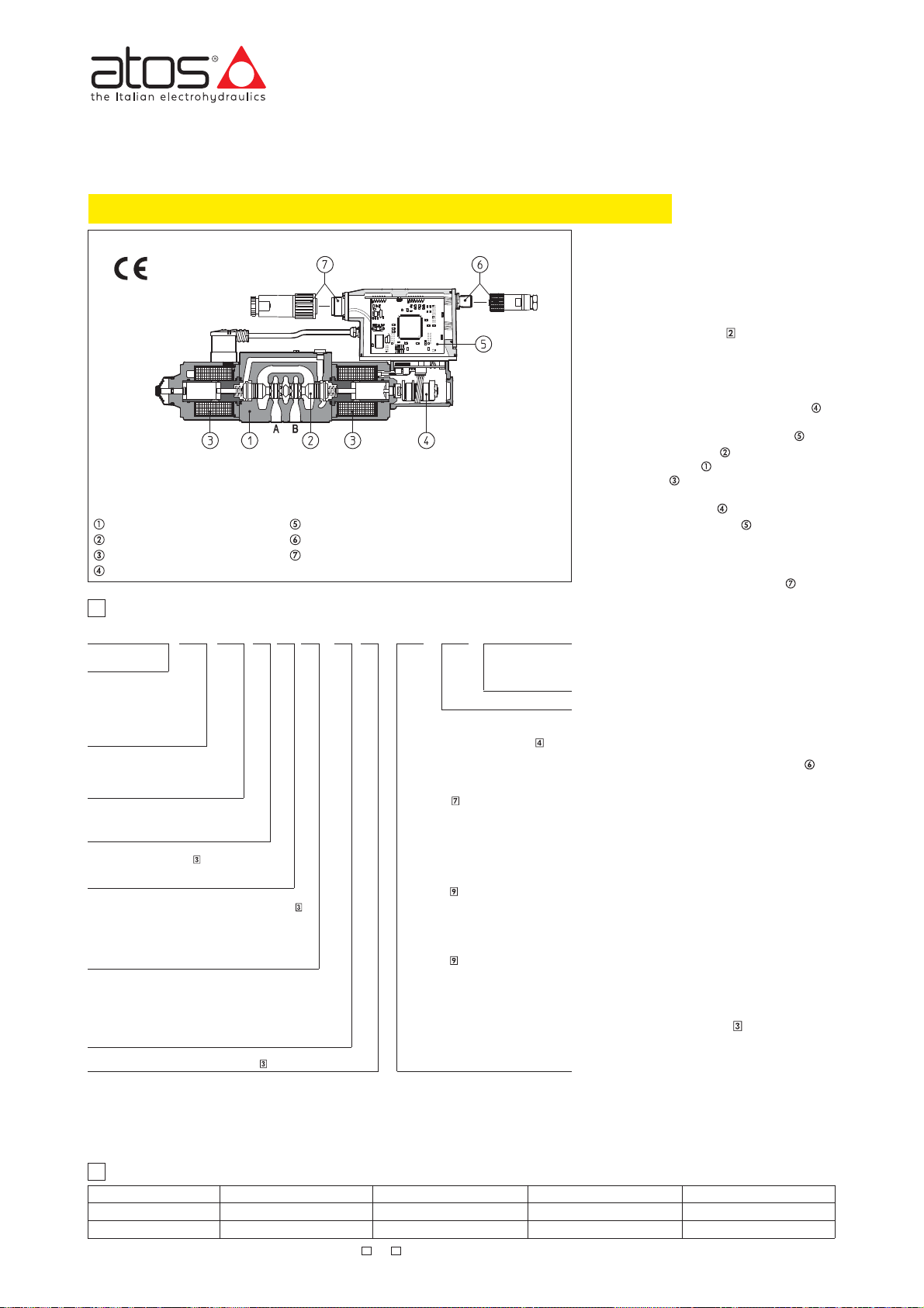
www.atos.com
Table F165-3/E
Proportional directional valves type DHZO-TES and DKZOR-TES
direct operated, with position transducer, ISO 4401 size 06 and 10
TE and TES executions included in this table are available only for running supplies or spare parts
For new applications it is suggested new TEB and TES executions, see table FS165
DHZO-T* and DKZOR-T* are proportional
valves, direct operated, with LVDT position
transducer, which provide both directional
and non-compensated flow control
according to the electronic reference
signal.
DKZOR-TES-PS-171
Valve body
Spool
Proportional solenoid
Position transducer
Integral electronics
Communication connector
Main connector
1 MODEL CODE
DHZO
DHZO = size 06
DKZOR = size 10
T = with position transducer
TE
= as T plus integral analog
electronics
TES = as T plus integral
digital electronics
TEZ = as TES plus digital axis
controller (1)
Communication interfaces
PS = Serial
BC = CANopen
BP = PROFIBUS DP
Valve size
0 = ISO 4401 size 06
1 = ISO 4401 size 10
Configuration, see section
5 = external plus central position, spring centered
7 = 3 position, spring centered
Spool overlapping in central position, see section
0 = zero overlapping (0 to 5 % spool stroke) (2)
1 = P,A,B,T positive overlapping (20% of spool stroke)
2 = P,A,B,T
3 = P positive overlapping (20% of spool stroke);
A, B, T, negative
Spool type (regulating characteristics)
L = linear;
S = progressive;
D = differential-progressive (as S, but with P-A = Q, P-B = Q/2)
Q = linear spool, for alternate P/Q controls (3)
V = differential-progressive, for alternate P/Q controls (4)
Spool size: 14, 1, 2, 3, 5, 9 = see section
Notes:
(1) For detailed description of proportional valves with TEZ digital axis controller, see table F230
(2) For zero overlapping spool 0L3, 0L5, 0D5, the valve offset position (with switch-off power supply) is 1 ÷ 6% P-B/A-T
(3) Only for DKZOR-*-S5 the spool overlapping type 2 provides the same characteristic of type 1, but in central position
(4) The spool type Q and V are specific for alternate P/Q controls and they can be used in combination with
TES PS
(only for TES)
positive overlapping with A-B draining (3)
the internal leakages from P to A and B are drained to tank, avoiding the drift of cylinders with differential areas.
option /S* of digital integral drivers (see section 13.1, 14.1 and G212), or digital axis controllers type Z-RI-TEZ
(see tab. F230) or Z-ME-KZ (see tab. G340)
0 7 -1 S 5 / /* ** / *- - -
Seals material:
omit for NBR (mineral
oil & water glycol)
PE = FPM
Series
number
Hydraulic options, see section :
B = solenoid, integral electronics and
position transducer at side of port A
Y = external drain
Electronics options, for -TE execution
see section
F =fault signal
I = current reference input and monitor
Q =enable signal
Z =enable, fault and monitor signals (12
Electronics options, for -TES execution
see section
I =
Z =
Special options for -TES execution
see section :
SF =
SL = additional closed loop force control
SP = additional closed loop pressure
C = current feedback interface for transdu-
:
(4÷20 mA)
pin connector)
:
current reference input and monitor
(4÷20 mA)
double power supply, enable fault and
monitor signals
additional closed loop force control,
with two remote pressure transducers
with one remote load cell
control with one remote pressure
transducer
cer(s) only for options /SF, /SL, /SP
(12 pin connector)
2 ELECTRONIC DRIVERS
Valve model
-T
Drivers model E-ME-T
Data sheet
G140
-TE
E-RI-TE
G200
Note: For power supply and communication connector see section 16 and 18
They operate in association with electronic
drivers, see section
proportional valves with proper current to
align v alve regulation to the reference
signal supplied to the electronic driver.
They are available in different executions:
• -T, with integral position transducer
• -TE, -TES as -T plus analog (TE) or
digital (TES) integral electronics
The 4-way spool
chambers body
solenoids
and it is controlled in closed
loop position by means of the LVDT
position transducer
The integral electronics ensures factory
presetting, fine functionality plus valve-tovalve interchangeability and simplified
wiring and installation.
The electronic main connector is fully
interchangeable for -TE and -TES
executions.
Standard 7 pin main connector is used for
power supply, analog input reference and
monitor signals.
12 pin connector is used for options /Z
and /S*.
The special /S* options add a closed loop
control of pressure (/SP) or force (/SF and
/SL) to the basic closed loop spool position one.
Following communication interfaces are
available for the digital -TES execution:
• -PS, Serial communication interface for
configuration, monitoring and firmware
updating through Atos PC software
• -BC, CANopen interface
• -BP, PROFIBUS DP interface
The valves with -BC and -BP interfaces
can be integrated into a fieldbus
communication network and thus digitally
operated by the machine control unit.
The coils are fully plastic encapsulated
(insulation class H) and the valves have
antivibration, antishock and weather-proof
features.
Mounting surface: ISO 4401 sizes 06 and 10.
Max flow respectively up to 50 l/min and
130 l/min with valve differential pressure
∆p = 30 bar, see table
Max pressure = 350 bar for DHZO;
-TES
E-RI-TES
G210
, which supply the
;
.
, sliding into a 5-
, is directly operated by
.
315 bar for DKZOR.
-TES / SF, SL, SP
E-RI-TES/SF, SL, SP
G212
F165
Page 59
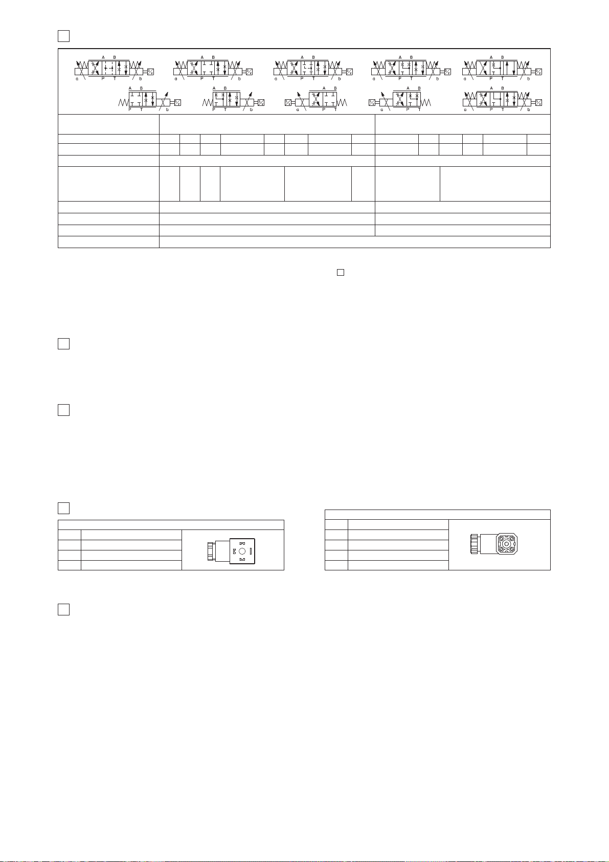
4
HYDRAULIC OPTIONS
4.1 Option /B
Solenoid (for valve configuration *5*), integral electronics and position transducer at side of port A. For version -T and -TE see section 13.1 and 14.1
4.2 Option /Y External drain advisable when the valve is used in double flow path, see section 13.5 and 14.5. Option /Y is mandatary if the pressure in
port T exceeds 160 bar.
Notes:
앬
For version DHZO-TE and DKZOR-TE, configuration /B, see the notes at sections 13.1 and 14.1
앬
Above performance data refer to valves coupled with Atos electronic drivers,
see sections .
앬
The flow regulated by the directional proportional valves is not pressure compensated, thus it is affected by the load variations.To keep costant the regulated
flow under different load conditions, modular pressure compensators are available (see tab. D150).
(1) For different Δp, the max flow is in accordance to the diagrams in sections 13.2 and 14.2
(2) 0-100% step signal
2
3
HYDRAULIC CHARACTERISTICS (based on mineral oil ISO VG 46 at 50 °C)
Valve model
DHZO-T*
Spool type and size
Spool overlapping
Max flow (1) [l/min]
at Δp = 10 bar (P-T)
at Δp = 30 bar (P-T)
at Δp = 70 bar (P-T)
Response time (2) [ms]
Hysteresis [%]
Repeatability [%]
Thermal drift
< 15
≤ 0,2%
± 0,1%
< 20
≤ 0,2%
± 0,1%
1
2
3
4,5
8
12
45
80
120
75
130
170
L14 L1
17
30
45
S3, L3, D3
28
50
74
S5, L5, D5 S3, L3, D3 S5, L5, D5
1, 3 1, 3
1, 3
1, 3
L5, D5
0
1, 3 1, 3
Hydraulic
symbols
*70 *71 *72 *73
DKZOR-T*
Pressure limits [bar] ports P, A, B = 350; T = 210 (250 with external drain /Y)
ports P, A, B = 315; T = 210 (250 with external drain /Y)
L5, D50S5
2
*51 *53 *51/B *53/B
zero point displacement < 1% at ΔT = 40°C
8
14
21
S2
1, 3
L3
0
L3
0
Q5, V9
3
Q5, V9
3
30
52
80
*73 V9
*73 Q5
GENERAL NOTES
5
DHZO and DKZOR proportional valves are CE marked according to the applicable Directives (e.g. Immunity/Emission EMC Directive and Low Voltage Directive).
Installation, wirings and start-up procedures must be performed according to the general prescriptions shown in table F003 and in the installation notes
supplied with relevant components.
The electrical signals of the valve (e.g. monitor signals) must not be directly used to activate safety functions, like to switch-ON/OFF the machine’s safety
components, as prescribed by the European standards (Safety requirements of fluid technology systems and components-hydraulics, EN-892).
CONNECTIONS FOR -T EXECUTION
6
PIN
1
2
3
SOLENOID POWER SUPPLY CONNECTOR
Signal description
SUPPLY
SUPPLY
GND
PIN
2
3
1
1
2
3
4
POSITION TRANSDUCER CONNECTOR
Signal description
OUTPUT SIGNAL
SUPPLY -15 V
SUPPLY +15 VDC
GND
DC
1
3
2
4
7 ANALOG INTEGRAL DRIVERS -TE - OPTIONS
Standard driver execution provides on the 7 pin main connector:
Power supply
- 24VDC must be appropriately stabilized or rectified and filtered; a 2,5 A safety fuse is required in series to the driver power supply.
Apply at least a 10000 μF/40 V capacitance to single phase rectifiers or a 4700 μF/40 V capacitance to three phase rectifiers
Reference input signal
Monitor output signal
- analog differential input with ±10 VDC nominal range (pin D,E), proportional to desired valve spool position
- analog output signal proportional to the actual valve’s spool position with ±10 VDC nominal range
Following options are available to adapt standard execution to special application requirements:
7.1 Option /F
It provides a Fault output signal in place of the Monitor output signal, to indicate fault conditions of the driver (cable interruption of spool transducers or
reference signal - for /I option): Fault presence corresponds to 0 V
DC, normal working corresponds to 24 VDC.
7.2 Option /I
It provides the 4÷20 mA current reference and monitor signals instead of the standard ±10 V
DC
It is normally used in case of long distance between the machine control unit and the valve or where the reference signal can be affected by electrical
noise; the valve functioning is disabled in case of reference signal cable breakage.
7.3 Option /Q
It provides the possibility to enable or disable the valve functioning without cutting the power supply (the valve functioning is disabled but the driver current output stage is still active). To enable the driver supply a 24V
DC on the enable input signal.
7.4 Option /Z
This option includes /F and /Q features, plus the Monitor output signal.
When the driver is disabled (0
VDC on enable signal) Fault option is forced to 0 VDC.
7.5 Possible combined options: /FI and /IZ
Page 60
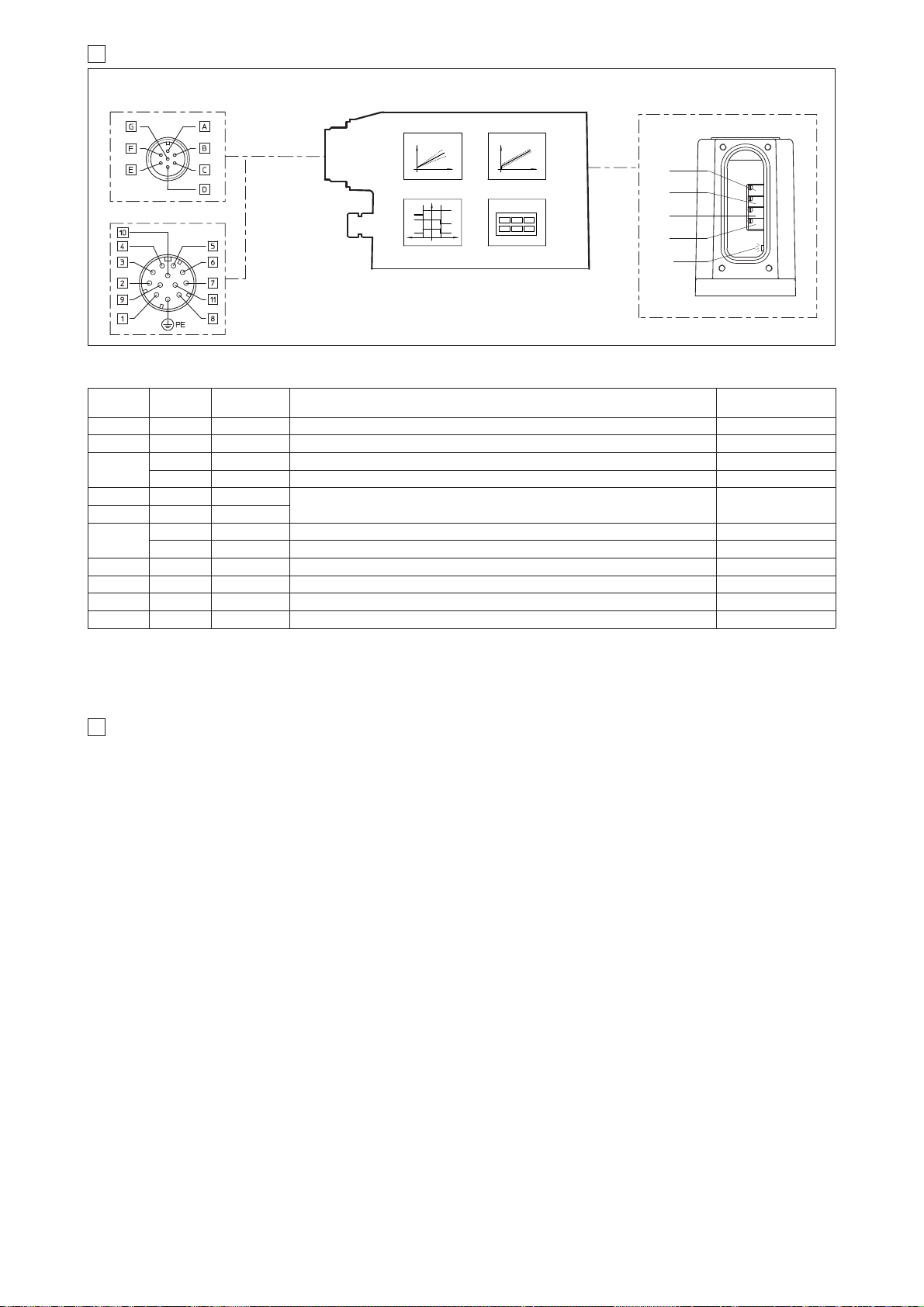
Standard
7pin
/Z option
12pin
SIGNAL
TECHNICAL SPECIFICATIONS
NOTES
A 1 V+ Power supply 24 VDC for solenoid power stage and driver logic
Input - power supply
Gnd - power supply
B 2 V0 Power supply 0 VDC for solenoid power stage and driver logic
C
(1)
7 AGND Ground - signal zero for MONITOR signal (for standard, /Z option) Input - analog signal
3 ENABLE Enable (24 VDC) or disable (0 VDC) the driver (for /Q and /Z options) Input - on/off signal
D 4 INPUT+
Reference analog differential input: ±10 VDCmaximum range (4 ÷ 20 mA for /I option)
For single solenoid valves the reference input is 0÷+10 VDC(4 ÷ 20 mA for /I option)
For double solenoid valves the reference input is ±10 V
DC
(4 ÷ 20 mA for /I option)
Input - analog signal
E 5 INPUT -
F
(2)
6 MONITOR Monitor analog output: ±10 VDC maximum range (4 ÷ 20 mA for /I option) Output - analog signal
11 FAULT Fault (0V) or normal working (24V) (for /F and /Z options) Output - on/off signal
- 8 R_ENABLE Repeat Enable - output repetition of Enable input Output - on/off signal
- 9 NC do not connect
Output - on/off signal
Output - on/off signal
- 10 NC do not connect
G PE EARTH
Internally connected to the driver housing
F165
9 DIGITAL INTEGRAL DRIVERS -TES - OPTIONS
8 ANALOG INTEGRAL DRIVERS -TE - MAIN FUNCTIONS AND ELECTRONIC CONNECTIONS
12 PIN - OPTION /Z
CURRENT TO COIL S2
(for double solenoid
valves)
REGULATIONS AND LED
7 PIN - STANDARD
MAIN CONNECTOR
BIAS
SCALE
DIAGNOSTIC
Notes
(1) with /Q option ENABLE signal replaces AGND on pin C; MONITOR signal is reffered to pin B
(2) with /F option FAULT signal replaces MONITOR on pin F.
앬
A minimum time of 50ms to 100ms have be considered between the driver energizing with the 24 VDC power supply and when the valve is ready to
operate. During this time the current to the valve coils is switched to zero.
B2
B1
S2
S1
positive bias adjust
LED:
H
H
H
H
STATE SIGNALS
LED
H
(driver view)
(driver view)
8.1 ELECTRONIC CONNECTIONS - 7 & 12 PIN MAIN CONNECTORS
negative bias adjust (only for double solenoid valves)
positive scale adjust
negative scale adjust (only for double solenoid valves)
OFF normal working; ON fault presence
B1:
B2:
S1:
S2:
Standard driver execution provides on the 7 pin main connector:
Power supply
- 24VDC must be appropriately stabilized or rectified and filtered; a 2,5 A safety fuse is required in series to each driver power supply
Apply at least a 10000 μF/40 V capacitance to single phase rectifiers or a 4700 μF/40 V capacitance to three phase rectifiers.
Reference input signal
- analog differential input with ±10VDC nominal range (pin D,E), proportional to desired valve spool position
Monitor output signal
- analog output signal proportional to the actual valve’s spool position with ±10VDC nominal range
Following options are available to adapt standard execution to special application requirements:
9.1 Option /I
It provides 4÷20 mA current reference and monitor signals instead of the standard ±10 V.
It is normally used in case of long distance between the machine control unit and the valve or where the reference signal can be affected by electrical
noise; the valve functioning is disabled in case of reference signal cable breakage.
9.2 Option /Z
It provides on the 12 pin main connector the following additional features:
Logic power supply
Separated power supply for the solenoid (pin 1, 2) and for the digital electronic circuits (pin 9, 10).
Cutting solenoid power supply allows to interrupt the valve functioning but keeping energized the digital electronics thus avoiding fault conditions of the
machine fieldbus controller. This condition allows to realize safety systems in compliance with European Norms EN13849-1 (ex EN954-1).
Enable Input Signal
To enable the driver, supply 24V
DC on pin 3 referred to pin 2: when the Enable signal is set to zero the valve functioning is disabled (zero current to the
solenoid) but the driver current output stage is still active.
Fault Output Signal
Fault output signal indicates fault conditions of the driver (solenoid short circuits/not connected, reference signal cable broken for 4÷20mA input, etc.).
Fault presence corresponds to 0
VDC
, normal working corresponds to 24
VDC (pin 11 referred to pin 2)
: Fault status is not affected by the Enable input signal
9.3 Options /SP, /SF and /SL
These options add the closed loop control of pressure (/SP) or force (/SF and /SL) to the basic functions of proportional directional valves: a dedicated
software alternates pressure (force) and valve’s spool position controls depending on the actual hydraulic system conditions.
A dedicated connector is available for the additional transducers that are required to be interfaced to the valve’s driver (1 pressure transducer for /SP,
2 pressure transducers for /SF or 1 load cell for /SL).
Main 12 pin connector is the same as /Z option plus two analog signals specific for the pressure (force) control: one for reference (pin 7) and one for
monitor (pin 8).
9.4 Options /C
Options /CSP, /CSF and /CSL are available to connect pressure (force) transducers with 4 ÷ 20mA current output signal.
9.5 Possible combined options: /ISP, /ISF, /ISL, /CSP, /CSF, /CSL, /CISP, /CISF, /CISL and /IZ
(remove the rear cover)
Page 61
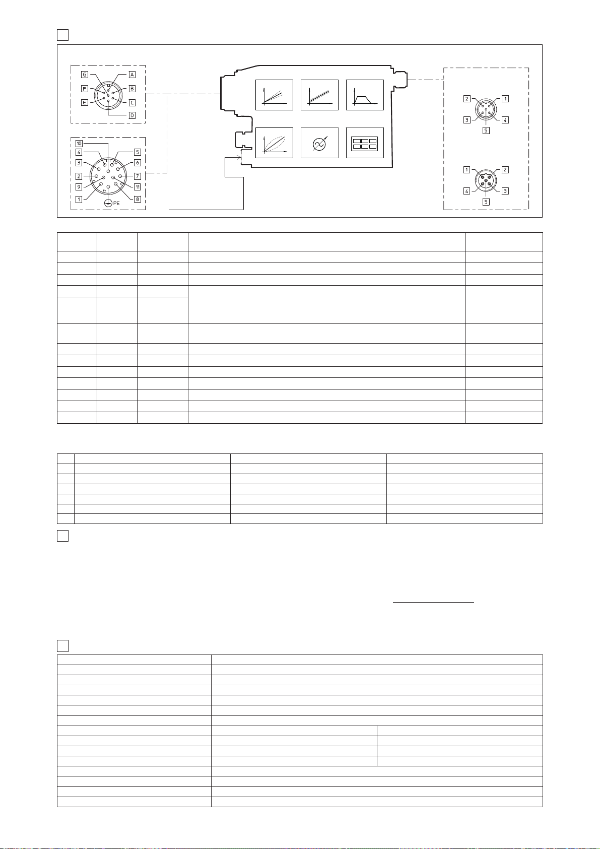
10.2 ELECTRONIC CONNECTIONS - 5 PIN COMMUNICATION CONNECTORS
10.1 ELECTRONIC CONNECTIONS - 7 & 12 PIN MAIN CONNECTORS
12 MAIN CHARACTERISTICS OF PROPORTIONAL DIRECTIONAL VALVES
-PS Serial -BC CANopen -BP PROFIBUS DP
PIN SIGNAL TECHNICAL SPECIFICATION SIGNAL TECHNICAL SPECIFICATION SIGNAL TECHNICAL SPECIFICATION
1 NC do not connect CAN_SHLD Shield +5V for termination
2 NC do not connect NC do not connect LINE-A Bus line (high)
3 RS_GND Signal zero data line CAN_GND Signal zero data line DGND data line and termination Signal zero
4 RS_RX Valves receiving data line CAN_H Bus line (high) LINE-B Bus line (low)
5 RS_TX Valves transmitting data line CAN_L Bus line (low) SHIELD
Standard
7pin
/Z option
12pin
SIGNAL TECHNICAL SPECIFICATIONS NOTES
A 1 V+
Power supply 24 VDC for solenoid power stage (and for driver logic on 7 pin connection)
Input - power supply
Gnd - power supply
B 2 V0 Power supply 0 VDC for solenoid power stage (and for driver logic on 7 pin connection)
- 3 ENABLE Enable (24 VDC) or disable (0 VDC) the driver Input - on/off signal
D 4 INPUT+
Reference analog input: ±10 VDC maximum range (4 ÷ 20 mA for /I option)
For single solenoid valves the reference input is 0÷+10 V
DC (4 ÷ 20 mA for /I option)
For double solenoid valves the reference input is ±10 V
DC (4 ÷ 20 mA for /I option)
standard: differential input; /Z option: common mode INPUT+ referred to AGND
Input - analog signal
E - INPUT -
C 5 AGND
Ground - signal zero for MONITOR signal
signal zero for INPUT+ signal (only for /Z option)
Gnd - analog signal
F 6 MONITOR Monitor analog output: ±10 VDC maximum range (4 ÷ 20 mA for /I option) Output - analog signal
- 7 NC do not connect (pressure/force input for /SP, /SF and /SL options, see 9.3 )
- 8 NC do not connect (pressure/force monitor for /SP, /SF and /SL options, see 9.3 )
- 9 VL+ Power supply 24 VDC for driver logic
Input - power supply
Gnd - power supply
- 10 VL0 Power supply 0 VDC for driver logic
- 11 FAULT Fault (0V) or normal working (24V) Output - on/off signal
G PE EARTH Internally connected to the driver housing
10 DIGITAL INTEGRAL DRIVERS -TES - MAIN FUNCTIONS AND ELECTRONIC CONNECTIONS
COMMUNICATION
CONNECTOR
12 PIN - OPTION /Z, /SP, /SF and /SL
7 PIN - STANDARD
5 PIN reverse key
PROFIBUS DP (-BP)
5 PIN
Serial (-PS) or
CANopen (-BC)
RAMPSBIASSCALE
LINEARIZATION
FIELDBUS
REFERENCE
ENHANCED
DIAGNOSTIC
REMOTE PRESSURE
(FORCE) TRANDUCER
(for /SP, /SF and /SL)
11
SOFTWARE TOOLS
MAIN CONNECTOR
Note: A minimum time of 300 to 500 ms have be considered between the driver energizing with the 24 VDC power supply and when the valve is ready
to operate. During this time the current to the valve coils is switched to zero.
(driver view)
(driver view)
CURRENT TO COIL S2
(for double solenoid
valves)
(driver view)
The driver configuration and parameters can be easily set with the Atos E-SW programming software, available in three different versions according to the
driver’s communication execution: E-SW-PS (Serial), E-SW-BC (CANopen) and E-SW-BP (PROFIBUS DP).
For a more detailed description of software interface, PC requirements, adapters, cables and terminators, please refer to technical table G500.
Programming software, must be ordered separately:
E-SW-* (mandatory - first supply) = Dvd including E-SW-* software installer and operator manuals; it allows the registration to Atos digital service
E-SW-*-N (optional - next supplies) = as above but not allowing the registration to Atos digital service
On first supply of the E-SW-* software, it is required to apply for the registration in the Atos download area: www.download.atos.com.
Once the registration is completed, the password will be sent by email.
The software remains active for 10 days from the installation date and then it stops until the user inputs his password.
With the password you can also download, in your personal area, the latest releases of the Atos software, manuals, drivers and configuration files.
Assembly position Any position
Subplate surface finishing Roughness index Ra 0,4 - flatness ratio 0,01/100 (ISO 1101)
Ambient temperature -20°C ÷ +70°C for -T execution; -20°C ÷ +60°C for -TE and TES executions
Fluid Hydraulic oil as per DIN 51524 ... 535 for other fluids see section
1
Recommended viscosity 15 ÷100 mm2/s at 40°C (ISO VG 15÷100)
Fluid contamination class ISO 4406 class 20/18/15 NAS 1638 class 9, in line filters of 10 μm (β
10 _>75 recommended)
Fluid temperature -20°C +60°C (standard seals and water glycol) -20°C +80°C (/PE seals)
Valve model DHZO-T* DKZOR-T*
Coil resistance R at 20°C 3 ÷ 3,3 Ω
3,8 ÷ 4,1
Ω
Max. solenoid current 2,6 A 3 A
Max. power 35 Watt 40 Watt
Insulation class H (180°) Due to the occuring surface temperatures of the solenoid coils, the European standards
ISO 13732-1 and EN982 must be taken into account
Protection degree (CEI EN-60529)
IP65 for -T execution; IP67 for -TE and -TES executions
Duty factor Continuous rating (ED=100%)
Page 62
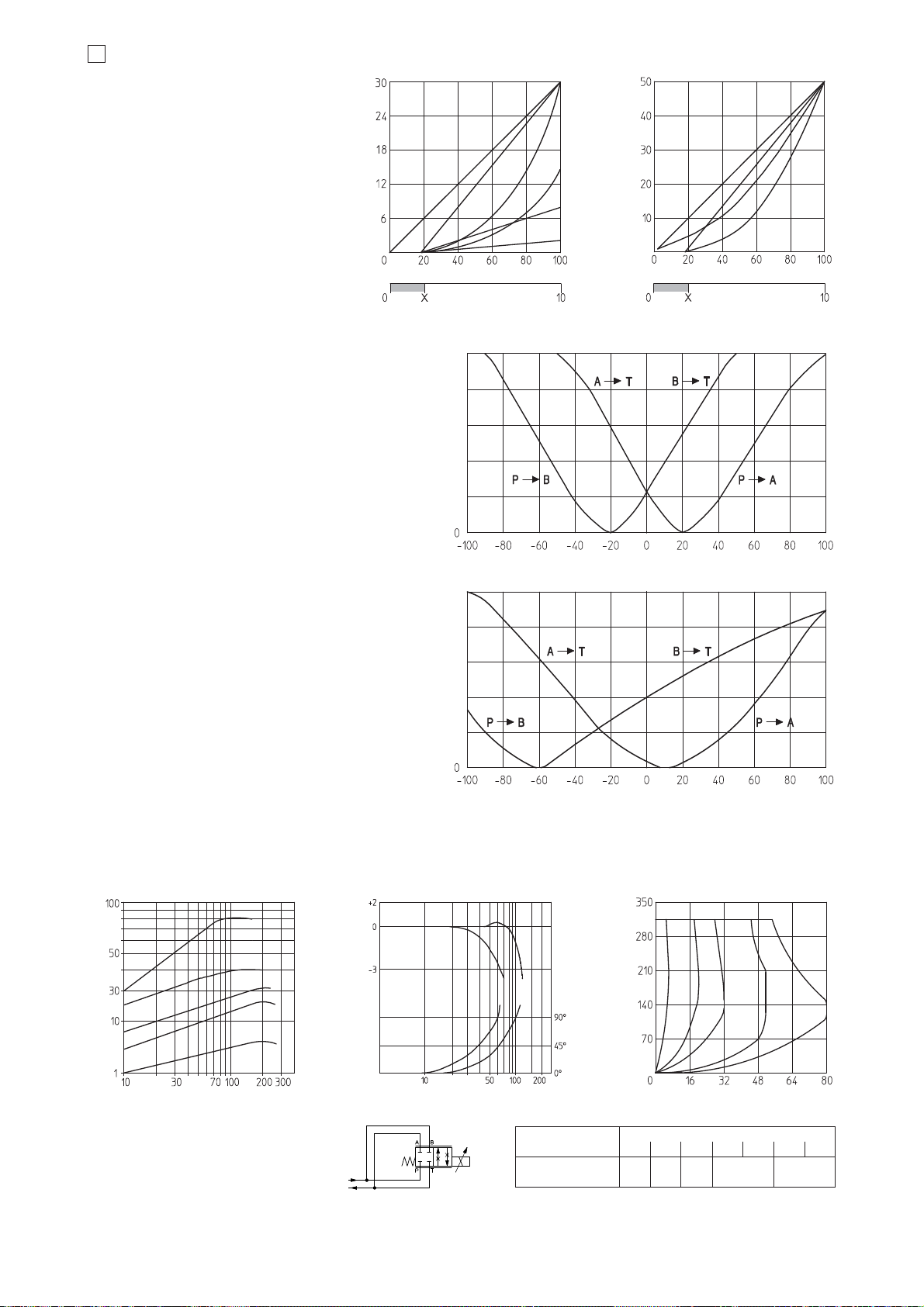
F165
13
DIAGRAMS FOR DHZO (based on mineral oil ISO VG 46 at 50 °C)
13.1 Regulation diagrams
1 = linear spool L14
2 = linear spool L1
3 = progressive spool S2
4 = linear spool L3
5 = progressive spool S3, D3
6 =
linear spool, zero overlapping
0L3
7 = linear spool L5
8 =
linear spool, zero overlapping
0L5
9 = progressive spool S5, D5
10=progressive spool, 0D5
zero overlapping
13.2 Flow /Δp diagrams
stated at 100% of valve stroke
1 = spool L14
2 = spool L1
3 = spool S2
4 = spool L3, S3, D3
5 = spool L5, S5, D5, V9
Max flow [l/min] at Δp = 30 bar
Max flow [l/min] at Δp = 30 bar
Stroke [% of max] Stroke [% of max]
2
5
9
4
13.5 Operation as throttle valve
Single solenoid valves (DHZO-*-051)
can be used as simple throttle valves:
Pmax = 250 bar (option /Y advisable)
13.6 Dynamic response
The response times in section
3
and the frequency responses in the bode diagrams have to be considered as average values.
For the valves with digital electronics the dynamics performances can be optimized by setting the internal software parameters.
Max flow Δp= 70bar
[l/min]
20 80 100
SPOOL TYPE
L1 L3 S3 L5 S5
12
12
13.3 Bode diagrams
1 = 10% vn 90% nominal stroke
2 = 50% ± 5% nominal stroke
Note:
Hydraulic configuration vs. reference signal
for double solenoid valves
(also for option /B)
Reference signal 0 ÷ +10 V
P n A / B n T
12 ÷ 20 mA
Reference signal 0 ÷ -10 V
P n B / A n T
4 ÷ 12 mA
Hydraulic configuration vs. reference signal
for mono solenoid valves
option /B
Reference signal 0 ÷ +10 V
P n B / A n T
12 ÷ 20 mA
Amplitude ratio [dB]
Frequency [Hz]
Phase [degrees]
1
Reference signal [V]
X = Threshold for bias activation depending to the valve type and amplifier type
Reference signal [V]
7
8
12 = differential - progressive spool V9
10
20
30
40
50
Max flow [l/min] at Δp = 30 bar
Stroke [% of max]
Flow rate [l/min]
Valve pressure drop Δp [bar]
Valve pressure drop Δp [bar]
Flow rate [l/min]
43
2
1
4
5
3
5
13.4 Operating limits
1 = spool L14
2 = spool L1
3 = spool S2
4 = spool L3, S3, D3
5 = spool L5, S5, D5, V9
40
S2
6
L14
3
6
12
10
Max flow [l/min] at Δp = 30 bar
Stroke [% of max]
11
21
11 = linear spool Q5
V9 spool type is specific for alternate P/Q controls and it can be used in combination with /S*
option of digital integral drivers, see tab. G212, or
digital position controllers type Z-RI-TEZ (see tab.
G330) or Z-ME-KZ (see tab. G340).
This spool is specially designed to manage the
whole injection cycle in plastic machinery, thanks
to the following specific features:
- strong meter-in characteristic to allow the pressure control in A port during the holding pressure (P-A) and the plasticizing (A-T) phases
- safety central position (A-T/B-T ) to depressurize
the actuator chambers
- large A-T and B-T flow capability, required
during the plasticizing phase, to discharge big
volumes from high differential injection cylinders
with low pressure drops and permitting the contemporary oil suction from tank
Q5 spool type is specific for alternate P/Q controls and it can be used in combination with /S*
option of digital integral drivers, see tab. G212, or
digital position controllers type Z-RI-TEZ (see tab.
G330) or Z-ME-KZ (see tab. G340).
It allows to control the pressure in A port or B port
and it provides a safety central position (A-T/B-T )
to depressurize the actuator chambers.
The strong meter-in characteristic makes the
spool suitable for both pressure control and
motion regulations in several applications.
10
20
30
40
50
Page 63
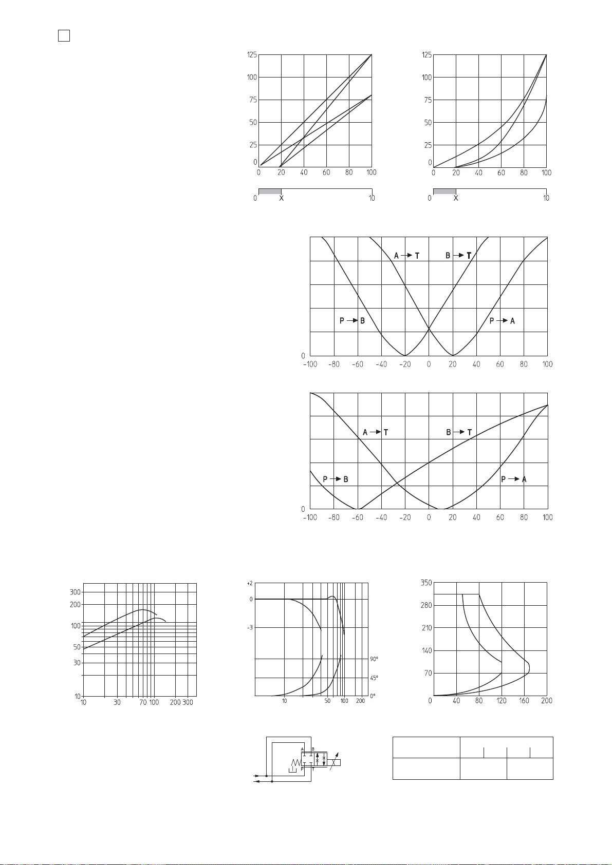
14
DIAGRAMS FOR DKZOR (based on mineral oil ISO VG 46 at 50 °C)
Max flow [l/min] at ΔP = 30 bar
Max flow [l/min] at ΔP = 30 bar
Stroke [% of max] Stroke [% of max]
1
2
6
4
14.5 Operation as throttle valve
Single solenoid valves (DKZOR-*-151)
can be used as simple throttle valves:
Pmax = 250 bar (option /Y advisable)
14.6 Dynamic response
The response times in section
3
and frequency responses in the bode diagrams have to be considered as average values.
For the valves with digital electronics the dynamics performances can be optimized by setting the internal software parameters.
150 250
SPOOL TYPE
L3 S3 L5 S5
Flow rate [l/min]
Valve pressure drop Δp [bar]
Valve pressure drop ΔP [bar]
Flow rate [l/min]
1
2
2
1
14.1 Regulation diagrams
1 = linear spool L3
2 = progressive spool S3, D3
3 =
linear spool, zero overlapping
0L3
4 = linear spool L5
5 =
linear spool, zero overlapping
0L5
6 = progressive spool S5, D5
7 = progressive spool, 0D5
zero overlapping
14.2 Flow /Δp diagrams
stated at 100% of valve stroke
1 = spool S3, L3, D3
2 = spool S5, L5, D5, V9
14.4 Operating limits
1 = spool L3, S3, D3
2 = spool L5, S5, D5, V9
Amplitude ratio [dB]
Frequency [Hz]
1
2
12
Phase [degrees]
Reference signal [V]
X = Threshold for bias activation depending to the valve type and amplifier type
Reference signal [V]
5
3
Max flow Δp= 30 bar
[l/min]
Note:
Hydraulic configuration vs. reference signal
for double solenoid valves
(also for option /B)
Reference signal 0 ÷ +10 V
P n A / B n T
12 ÷ 20 mA
Reference signal 0 ÷ -10 V
P n B / A n T
4 ÷ 12 mA
Hydraulic configuration vs. reference signal
for mono solenoid valves
option /B
Reference signal 0 ÷ +10 V
P n B / A n T
12 ÷ 20 mA
7
14.3 Bode diagrams
1 = 10% vn 90% nominal stroke
2 = 50% ± 5% nominal stroke
9 = differential - progressive spool V9
30
60
90
120
150
Max flow [l/min] at Δp = 30 bar
Stroke [% of max]
9
Max flow [l/min] at Δp = 30 bar
Stroke [% of max]
8
8 = linear spool Q5
V9 spool type is specific for alternate P/Q controls and it can be used in combination with /S*
option of digital integral drivers, see tab. G212, or
digital position controllers type Z-RI-TEZ (see tab.
G330) or Z-ME-KZ (see tab. G340).
This spool is specially designed to manage the
whole injection cycle in plastic machinery, thanks
to the following specific features:
- strong meter-in characteristic to allow the pressure control in A port during the holding pressure (P-A) and the plasticizing (A-T) phases
- safety central position (A-T/B-T ) to depressurize
the actuator chambers
- large A-T and B-T flow capability, required
during the plasticizing phase, to discharge big
volumes from high differential injection cylinders
with low pressure drops and permitting the contemporary oil suction from tank
Q5 spool type is specific for alternate P/Q controls and it can be used in combination with /S*
option of digital integral drivers, see tab. G212, or
digital position controllers type Z-RI-TEZ (see tab.
G330) or Z-ME-KZ (see tab. G340).
It allows to control the pressure in A port or B port
and it provides a safety central position (A-T/B-T )
to depressurize the actuator chambers.
The strong meter-in characteristic makes the
spool suitable for both pressure control and
motion regulations in several applications.
25
50
75
100
125
Page 64
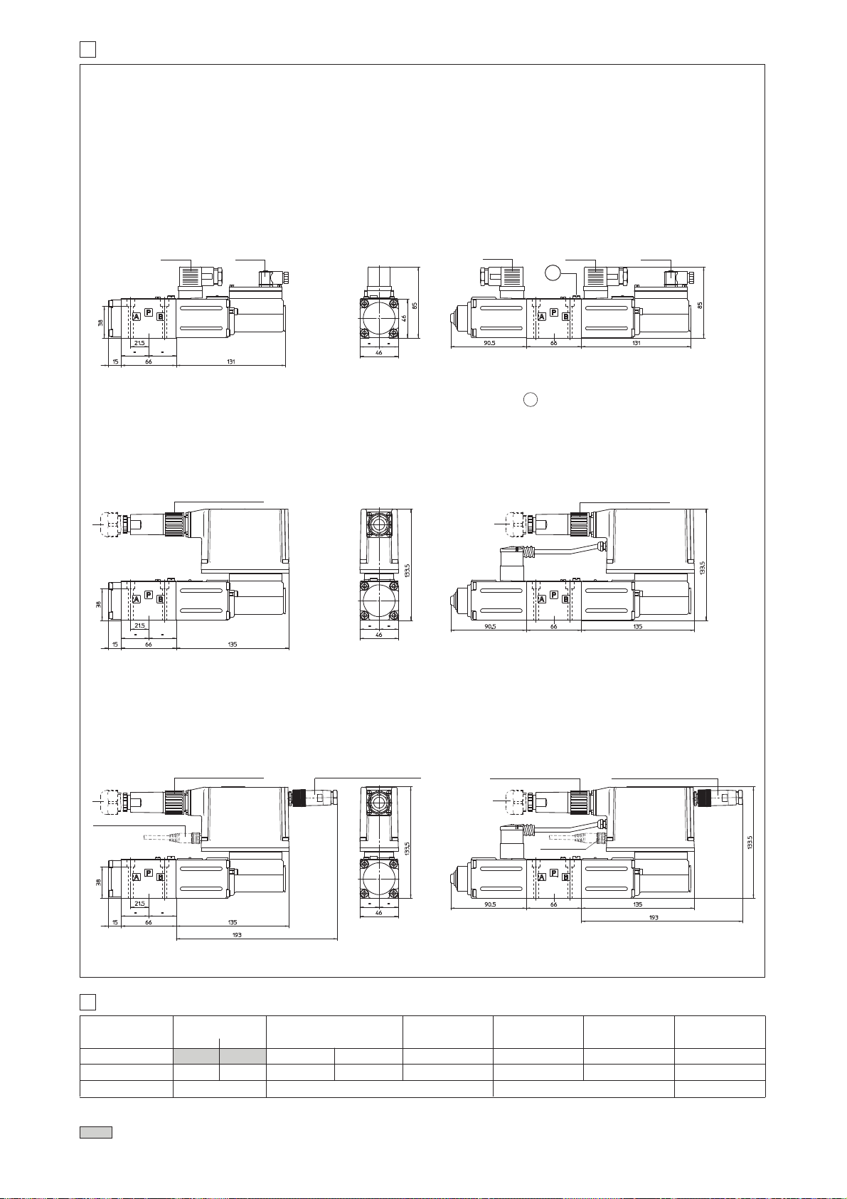
15 INSTALLATION DIMENSIONS FOR DHZO [mm]
ISO 4401: 2000
Mounting surface
(for /Y surface 4401-03-03-0-05 without X port)
: 4401-03-02-0-05
(see table P005)
Fastening bolts: 4 socket head screws M5x50 class 12.9
Tightening torque = 8 Nm
Seals: 4 OR 108; 1 OR 2025
Diameter of ports A, B, P, T: Ø 7,5 mm (max)
Diameter of port Y: Ø = 3,2 mm (only for /Y option)
DHZO-T-05
SP-666 SP-345
DHZO-T-07
SP-666
Mass: 1,9 kg
Note: for option /B the solenoid and the position transducer are at side of port A
-TE EXECUTION
쩸
Dotted line =12 pin connector SP-ZH-12P for option /Z
DHZO-TE-05 DHZO-TE-07
SP-ZH-7P or SP-ZM-7P
SP-666
V
V
= Air bleed off
SP-345
Mass: 2,6 kg
SP-ZH-7P or SP-ZM-7P
쩸
쩸
Mass: 2,3 kg
-TES EXECUTION
쩸
Dotted line =12 pin connector SP-ZH-12P for options /SF, /SL, /SP, /Z
쩹
Dotted line = M8 connector SP-ZH-4P-M8/5 moulded on cable 5 mt lenght for pressure or force transducer (options /SL, /SP)
M8 connector SP-ZH-4P-M8/2-2 moulded with 2 cables, 2 mt lenght for 2 pressure transducers (options /SF)
DHZO-TES-*-05 DHZO-TES-*-07
SP-ZH-7P or SP-ZM-7P
쩸
SP-ZH-5P/BP (for -BP)
SP-ZH-5P (for -PS and -BC)
SP-ZH-7P or SP-ZM-7P
쩸
쩹
쩹
Mass: 3,1 kg
SP-ZH-5P/BP (for -BP)
SP-ZH-5P (for -PS and -BC)
Mass: 3,1 kgMass: 2,3 kg
Note: for option /B the solenoid, the position transducer and the integral electronics are at side of port A
16
MODEL CODES OF POWER SUPPLY AND COMMUNICATION CONNECTORS (to be ordered separately)
VALVE VERSION
CONNECTOR CODE
PROTECTION DEGREE
DATA SHEET
-T
Power supply Transducer
SP-666
SP-345
IP65
IP65 IP67 IP67 IP67 IP67 IP67
K500 G200, G210, K500 G210, K500
-TE, -TES
SP-ZH-7P SP-ZM-7P SP-ZH-12P SP-ZH-5P SP-ZH-5P/BP
-TE /Z
-TES /Z, /SF, /SL, /SP
serial (-PS)
or CANopen (-BC)
(1) M8 connector SP-ZH-4P-M8/5 moulded on cable 5 mt lenght for pressure or force transducer (options /SL, /SP)
M8 connector SP-ZH-4P-M8/2-2 moulded with 2 cables, 2 mt lenght for 2 pressure transducers (options /SF)
connectors supplied with the valve
PROFIBUS DP (-BP)
TES /SF, /SL, /SP
(transducer)
SP-ZH-4P-M8/*
IP67
G212, K500
(1)
F165
Page 65
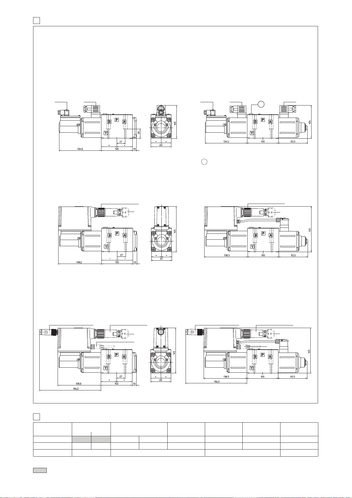
17 INSTALLATION DIMENSIONS FOR DKZOR [mm]
ISO 4401: 2000
Mounting surface
(for /Y surface 4401-05-05-0-05 without X port)
: 4401-05-04-0-05
(see table P005)
Fastening bolts: 4 socket head screws M6x40 class 12.9
Tightening torque = 15 Nm
Seals: 5 OR 2050; 1 OR 108
Diameter of ports A, B, P, T: Ø 11,2 mm (max)
Diameter of port Y: Ø = 5 mm (only for /Y option)
DKZOR-T-15
SP-345
SP-666
DKZOR-T-17
SP-345
Mass: 3,8 kg
V
Note: for option /B the solenoid and the position transducer are at side of port A
= Air bleed off
-TE EXECUTION
쩸
Dotted line =12 poles connector SP-ZH-12P for option /Z
DKZOR-TE-15 DKZOR-TE-17
SP-ZH-7P or SP-ZM-7P
SP-666
V
SP-ZH-7P or SP-ZM-7P
SP-666
Mass: 4,5 kg
쩸
Mass: 4,3 kg
-TES EXECUTION
쩸
Dotted line =12 pin connector SP-ZH-12P for options /SF, /SL, /SP, /Z
Dotted line = M8 connector SP-ZH-4P-M8/5 moulded on cable 5 mt lenght for pressure or force transducer (options /SL, /SP)
쩹
M8 connector SP-ZH-4P-M8/2-2 moulded with 2 cables, 2 mt lenght for 2 pressure transducers (options /SF)
DKZOR-TES-*-15 DKZOR-TES-*-17
SP-ZH-5P/BP (for -BP)
SP-ZH-5P (for -PS and -BC)
SP-ZH-7P or SP-ZM-7P
SP-ZH-5P/BP (for -BP)
SP-ZH-5P (for -PS and -BC)
쩸
쩹
쩸
Mass: 5,0 kg
SP-ZH-7P or SP-ZM-7P
쩸
쩹
Note: for option /B the solenoid, the position transducer and the integral electronics are at side of port A
18
MODEL CODES OF POWER SUPPLY AND COMMUNICATION CONNECTORS (to be ordered separately)
VALVE VERSION
CONNECTOR CODE
PROTECTION DEGREE
DATA SHEET
-T
Power supply Transducer
SP-666
SP-345
IP65
IP65 IP67 IP67 IP67 IP67 IP67
K500 G200, G210, K500 G210, K500
-TE, -TES
SP-ZH-7P SP-ZM-7P SP-ZH-12P SP-ZH-5P SP-ZH-5P/BP
-TE /Z
-TES /Z, /SF, /SL, /SP
serial (-PS)
or CANopen (-BC)
(1) M8 connector SP-ZH-4P-M8/5 moulded on cable 5 mt lenght for pressure or force transducer (options /SL, /SP)
M8 connector SP-ZH-4P-M8/2-2 moulded with 2 cables, 2 mt lenght for 2 pressure transducers (options /SF)
connectors supplied with the valve
11/11
PROFIBUS DP (-BP)
Mass: 4,7 kgMass: 4 kg
TES /SF, /SL, /SP
(transducer)
SP-ZH-4P-M8/*
IP67
G212, K500
(1)
Page 66
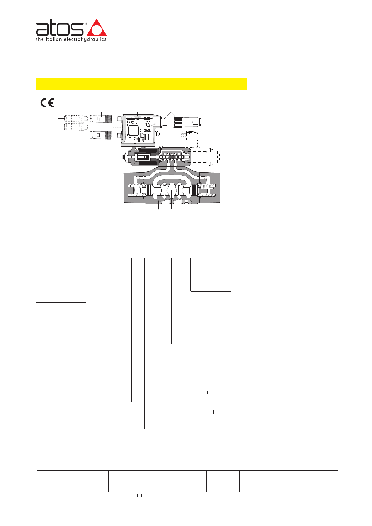
Valve size:
1 = 10 2 = 16 4 = 25 6 = 32
www.atos.com
Proportional directional valves type DPZO-AES
two stage without position transducer, ISO 4401 sizes 10, 16, 25 and 32
Table F170-23/E
DPZO
Piloted
proportional
directional valve
Spool overlapping in central position, see sect. 쪩:
1 = P, A, B, T positive overlapping (2)
3 = P positive overlapping A, B, T negative
overlapping
Spool type
L= linear
S = progressive
D=as S, but with P-A = Q, P-B = Q/2
Spool size: 3 and 5
,
see section
쪩
Series number
AES PS 72-D15*/*/*---
1 MODEL CODE
F170
Configuration, see section 쪩:
5 = external plus central position, spring
centered
7 = 3 positions; spring centered
A = without position tran-
sducer
AE = as A plus integral
electronics
AES = as A plus integral
digital electronics
Communication interfaces
only for AES (1)
PS = USB
BC = CANopen
BP = PROFIBUS DP
EH = EtherCAT
DPZO-A* are two stage proportional valves without position transducer, which
provide both directional and non compensated flow control according to the electronic reference signal.
They operate in association with electronic drivers, see section
쪨
, which supply
the proportional valves with correct current signal to align valve regulation to the
reference signal supplied to the electronic
driver.
They are available in different executions:
• -A, without position transducer;
• -AE, -AES as -A plus analogue (AE) or
digital (AES) integral electronics
쩻
;
The 4-way spool , sliding into a 5chambers body , is piloted in open loop
by the proportional pressure reducing
valve
type DHRZO.
The integral electronics
ensures factory
presetting, fine functionality plus valve-tovalve interchangeability and simplified
wiring and installation.
The electronic main connector 쩼 is fully
interchangeable for -AE and -AES
executions.
Standard 7 pin main connector is used for
power supply, analog input reference and
monitor signals.
12 pin connector is used for options /Z, /W
(AES).
Following communication interfaces ,
are available for the digital -AES execution:
• standard -PS, Serial communication
interface for configuration, monitoring
and firmware updating through Atos PC
software - always present, also for -BC, BP and -EH options
• optional -BC, CANopen interface
•
optional -BP, PROFIBUS DP interface
•
-EH, EtherCAT interface
The valves with -BC, -BP and -EH
interfaces can be integrated into a fieldbus
communication network and thus digitally
operated by the machine control unit.
Surface mounting: ISO 4401
Size 10, 16, 25 and 32.
Max flow respectively up to:
160 l/min, 430 l/min, 720 l/min and 1000
l/min with valve differential pressure Δp = 30
bar, see section
쪩
.
Max pressure: 350 bar
A
B
Notes:
(1) USB interface always present, also for -BC
and -BP
and -EH
options
(2) Overlapping = 20% of spool stroke for type S
and D, 10% of spool stroke for type L
Coil voltage (only for -A execution)
see section 쪮:
- = standard coil for 24V
DC
Atos drivers
6 = optional coil for 12VDCAtos
drivers
18 = optional coil for low cur-
rent drivers
*
2
ELECTRONIC DRIVERS FOR DPZO-A*
DPZO-AES-*-251-*
DPZO-AES-*-271-* (dotted line)
Note: for main and communication connector see section
14
Valve body
Main stage Spool
Pilot valve
Integral electronics
Main connector
-BC or -BP communication connector
-PS communication connector (3)
-EH Communication connector (input)
-EH Communication connector (output)
Valve model
Data sheet
Drivers model E-MI-AC-0*F
G010
E-BM-AS-PS
G030
E-ME-AC-0*F
G035
-A
-AES
-AE
E-RP-AC-0*F
G100
E-RI-AE
G110
E-RI-AES
G115
E-BM-AC-0*F
G025
E-MI-AS-IR
G020
Seals material,
see section
쪪
:
- =
NBR
PE = FKM
BT = HNBR
(only -A)
Hydraulic options, see sect. 쪬:
B =
solenoid and integral electronics at side of port B of the main
stage (side A of pilot valve);
D =internal drain
E = external pilot
G =pressure reducing valve for
piloting
Electronics options for -AE execution, see section :
I = current reference input (4÷20 mA)
Q =enable signal
Electronics options for -AES
execution, see section :
Q = enable signal
Z =double power supply, enable
fault and monitor (12 pin connector)
W =power limitation function (12
pin connector) see sect. 11.3
10
12
AES execution included in this table is available only for running supplies or spare parts
For new applications it is suggested new AEB and AES executions, see table FS170
Page 67
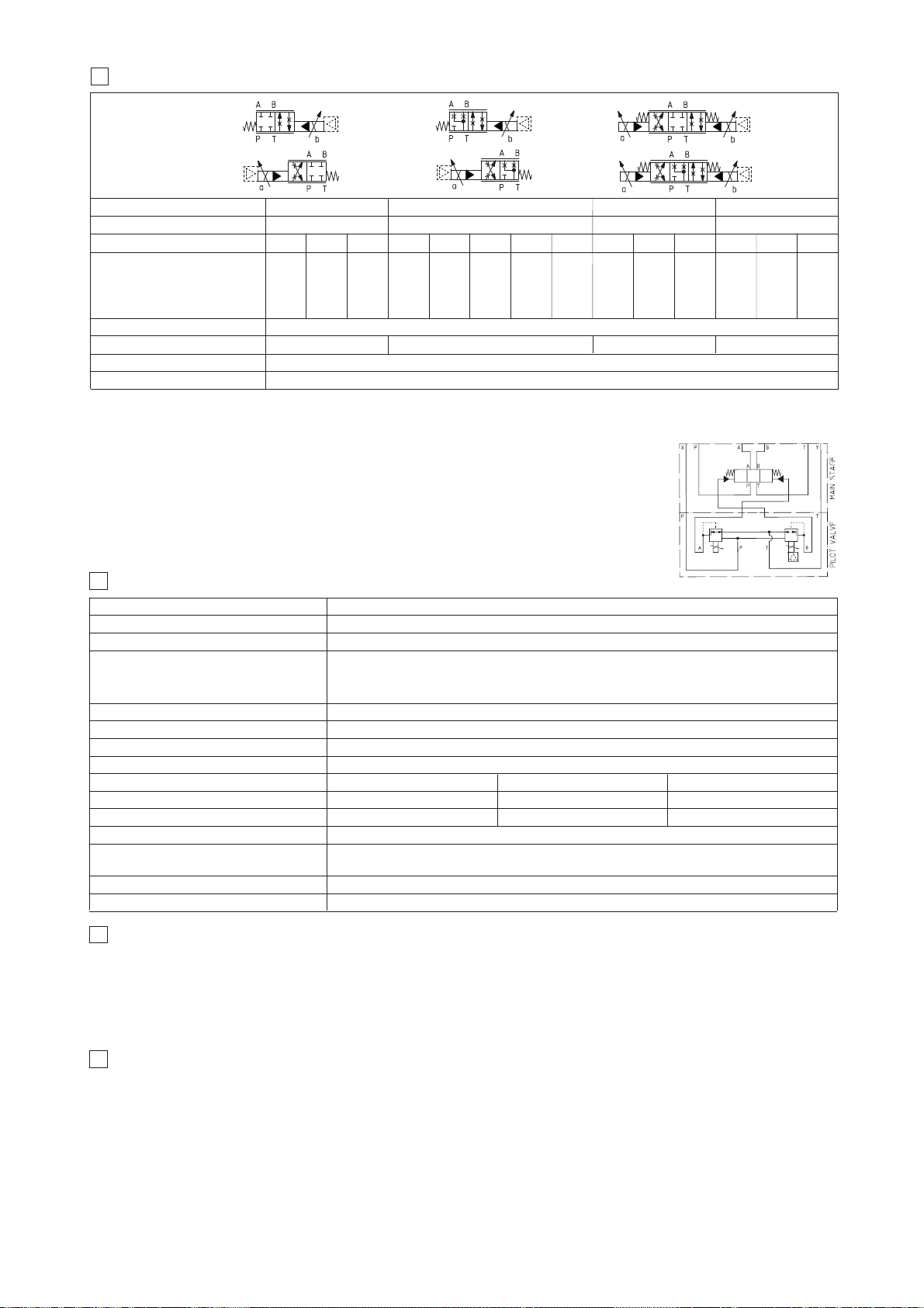
DPZO-A* proportional valves are CE marked according to the applicable Directives (e.g. Immunity/Emission EMC Directive and Low Voltage Directive).
Installation, wirings and start-up procedures must be performed according to the general prescriptions shown in table F003 and in the installation notes
supplied with relevant components.
The electrical signals of the valve (e.g. monitor signals) must not be directly used to activate safety functions, like to switch-ON/OFF the machine’s safety
components, as prescribed by the European standards (Safety requirements of fluid technology systems and components-hydraulics, EN-982).
5
GENERAL NOTES
3
HYDRAULIC CHARACTERISTICS (based on mineral oil ISO VG 46 at 50 °C)
Valve model
Spool overlapping
Spool type and size
DPZO-1 DPZO-2
Max flow (1) [l/min]
at
Δ
p = 10 bar (P-T)
at
Δ
p = 30 bar (P-T)
max permissible flow
100
160
180
160
270
400
S3L5
100
160
180
S5
100:60
160:100
180:110
D5
Hydraulic symbols
*71
*73
*51
*53
*51/B
*53/B
Hysteresis [%]
Repeatability
Response time [ms]
(3)
Pressure limits (2) [bar]
ports P, A, B, X = 350; T = 250 (5 for option /D); Y = 5
Notes:
For version DPZO-A and DPZO-AE, configuration /B, see the notes at section 6.1
Above performance data refer to valves coupled with Atos electronic drivers, see section
쪨
.
In case of long time shutdown of the hydraulic supply to the pilot valve, the driver has to be switched off to avoid
its overheating.
The flow regulated by the directional proportional valves is not pressure compensated, thus it is affected by
the load variations.To keep costant the regulated flow under different load conditions, modular pressure
compensators are available (see tab. D150).
(1) For different
Δ
p, the max flow is in accordance to the diagrams in section 13.2
(2) Minimum piloting pressure = 30 bar
(3) 0-100% step signal
< 100
< 180< 120
< 80
≤ 5%
± 1%
1, 3
1, 3
160:98
270:160
400:245
D3
250
430
550
L5
225
390
550
S5
DPZO-4
420
720
900
L5
1, 3
400
690
900
S5
400:245
690:420
900:550
D5
DPZO-6
600
1000
1600
L5
1, 3
600
1000
1600
S5
600:370
1000:620
1600:990
D5
225:160
390:280
550:390
D5
6
HYDRAULIC OPTIONS
6.1 Option /B DPZO-*-*5 = solenoid and integral electronics at side of port B of the main stage.
DPZO-*-*7 = integral electronics at side of port B of the main stage.
For hydraulic configuration vs. reference signal, see section 13.1
6.2 Pilot and drain configuration -The pilot / drain configuration can be modified as shown in the table E085 section 12.
The valve’s standard configuration provides internal pilot and external drain. For different pilot / drain configuration select:
Option /E External pilot (through port X).
Option /D Internal drain.
Option /G Pressure reducing valve with fixed setting (= 40 bar for DPZO-1 and -2; 100 bar for DPZO-4 and -6) installed between pilot valve and
main body.
It is advisable for valves with internal pilot in case of system pressure higher than 200 bar.
102
FUNCTIONAL SCHEME
example of configuration 7
(3 positions, spring centered)
Assembly position Any position
Subplate surface finishing Roughness index, Ra 0,4 flatness ratio 0,01/100 (ISO 1101)
MTTFd valves according to EN ISO 13849 75 years, for further details, see technical table P007
-A execution = -20°C ÷ +70°C (storage -20°C ÷ +80°C) /BT option -40°C ÷ +60°C (storage -40°C ÷ +70°C)
Ambient temperature -AE execution = -20°C ÷ +60°C (storage -20°C ÷ +70°C)
-AES execution = -20°C ÷ +60°C (storage -20°C ÷ +70°C)
Fluid Hydraulic mineral oil HL, HLP as per DIN 51524
Recommended viscosity 20÷100 mm
2
/s - max allowed range 15 ÷ 380 mm2/s
Fluid contamination class ISO 4406 class 20/18/15 NAS 1638 class 9, in line filters of 10 μm (β10 _>75 recommended)
Fluid temperature -20°C +60°C (standard seals) -20°C +80°C (/PE option) -40°C +60°C (/BT option)
4 MAIN CHARACTERISTICS
Coil code Standard Option /6 Option /18
Coil resistance R at 20°C 3 ÷ 3,3 Ω 2 ÷ 2,2 Ω 13 ÷ 13,4 Ω
Max. solenoid current 1,9 A 2,35 A 0,9 A
Max. power
-A execution = 35 Watt -AE and -AES executions = 50 Watt
Insulation class
H (180°) Due to the occuring surface temperatures of the solenoid coils, the European standards
ISO 13732-1 and EN982 must be taken into account
Protection degree to DIN EN60529
-A execution = IP65 -
AE, and -AES
executions = IP67
Duty factor Continuous rating (ED=100%)
Page 68
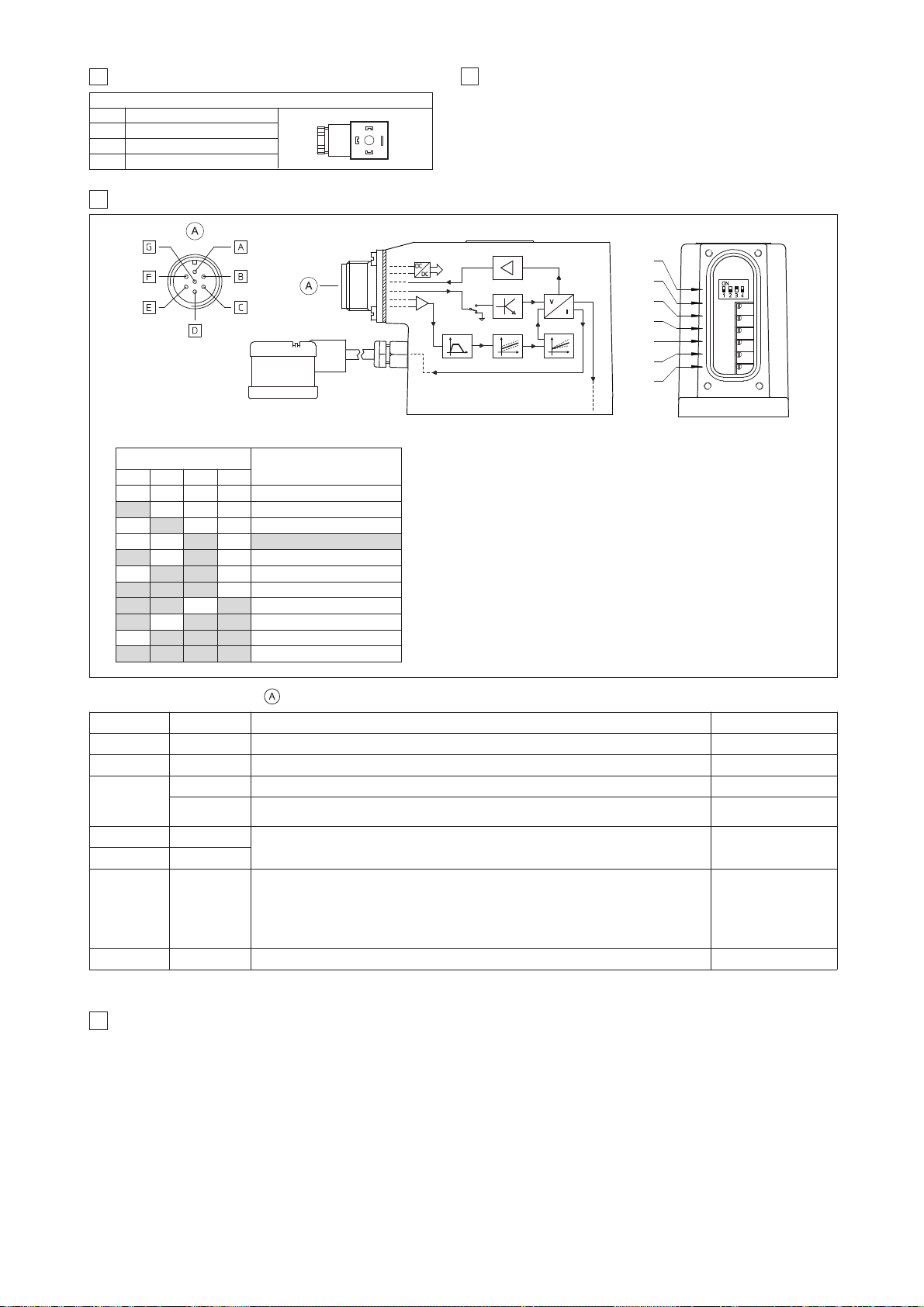
positive bias adjust
negative bias adjust (only for double solenoid valves)
positive scale adjust
negative scale adjust (only for double solenoid valves)
B1:
B2:
S1:
S2:
ramp for increasing reference signal
ramp for decreasing reference signal
RU:
RD:
F170
dither frequency selector (see table beside)
SW:
• A minimum time of 60ms to 160ms have be considered between the driver energizing with the 24 VDC power supply and when the valve is ready to
operate. During this time the current to the valve coils is switched to zero
10 ANALOG INTEGRAL DRIVERS -AE - OPTIONS
Standard driver execution provides on the 7 pin main connector:
Power supply
- 24VDC must be appropriately stabilized or rectified and filtered; a 2,5 A safety fuse is required in series to the driver power supply.
Apply at least a 10000 μF/40 V capacitance to single phase rectifiers or a 4700 μF/40 V capacitance to three phase rectifiers
Reference input signal
- analog differential input with ±10 VDC nominal range (pin D,E), proportional to desired coil current.
Monitor output signal
- analog output signal proportional to the actual valve’s coil current (1V monitor = 1A coil current)
Following options are available to adapt standard execution to special application requirements:
10.1 Option /I
It provides the 4÷20 mA current reference signal instead of the standard ±10 V
DC. Monitor output signal is still the standard ±10 VDC.
It is normally used in case of long distance between the machine control unit and the valve or where the reference signal can be affected by electrical
noise; the valve functioning is disabled in case of reference signal cable breakage.
10.2 Option /Q
It provides the possibility to enable or disable the valve functioning without cutting the power supply (the valve functioning is disabled but the driver current output stage is still active). To enable the driver supply a 24VDC on the enable input signal.
10.3 Possible combined options: /IQ
7
CONNECTIONS FOR -A EXECUTION
Signal description
SUPPLY
SUPPLY
GND
PIN
1
2
3
SOLENOID POWER SUPPLY CONNECTOR
1
2
3
8
OPTIONS FOR -A EXECUTION
Option /6 optional coil to be used with Atos drivers with power supply 12 VDC
Option /18 optional coil to be used with electronic drivers not supplied by Atos
9 ANALOG INTEGRAL DRIVER -AE -ELECTRONIC CONNECTIONS AND SETTINGS
COIL CONNECTION
(only for double solenoid valves)
Note:
Connector front view
MAIN CONNECTOR
(male)
MONITOR
ENABLE
DEAD BANDRAMPS SCALE
DC/DC
CONVERTER
CURRENT
TO COIL S1
CURRENT
TO COIL S2
(for E-RI-AE-*-05F)
Selector SW
Dither frequency
[Hz]
SW1 SW2 SW3 SW4
OFF OFF OFF OFF
100
ON OFF OFF OFF
130
OFF ON OFF OFF
160
OFF OFF ON OFF
200 (*)
ON OFF ON OFF
230
OFF ON ON OFF
270
ON ON ON OFF
300
ON ON OFF ON
380
ON OFF ON ON
430
OFF ON ON ON
470
ON ON ON ON
500
(*) Dither frequency is factory preset at 200 Hz and its regulation may be
adjusted after contact Atos technical office.
PIN SIGNAL TECHNICAL SPECIFICATIONS NOTES
A V+ Power supply 24 VDC for solenoid power stage and driver logic Input - power supply
B V0 Power supply 0 VDC for solenoid power stage and driver logic Gnd - power supply
C
AGND Ground - signal zero for MONITOR signal Gnd - analog signal
ENABLE
Enable (24 VDC) or disable (0 VDC) the driver (for /Q option)
With /Q option:ENABLE signal replaces AGND on pin C; MONITOR signal is reffered to pin B
Input - on/off signal
D INPUT+
Reference analog differential input: ±10 VDC maximum range (4 ÷ 20 mA for /I option)
For single solenoid valves the reference input is 0 ÷ 10 V
DC (4 ÷ 20 mA for /I option)
For double solenoid valves the reference input is ±10 V
DC (4 ÷ 20 mA for /I option)
Input - analog signal
E INPUT -
F MONITOR
Monitor analog output: ±5 VDC maximum range (1V monitor = 1A coil current)
For single solenoid valves: 0 ÷ 5 V
DC referred to pin C (for /I option)
0 ÷ 5 V
DC referred to pin B (for /Q option)
For double solenoid valves: ±5 V
DC referred to pin C (for /I option)
±5 V
DC referred to pin B (for /Q option)
Output - analog signal
G EARTH
Internally connected to the driver housing
9.1 MAIN CONNECTOR - 7 pin
SETTINGS
remove the rear cover
SW
RD
RU
B2
B1
S2
S1
RD
RU
B2
B1
S2
S1
Page 69
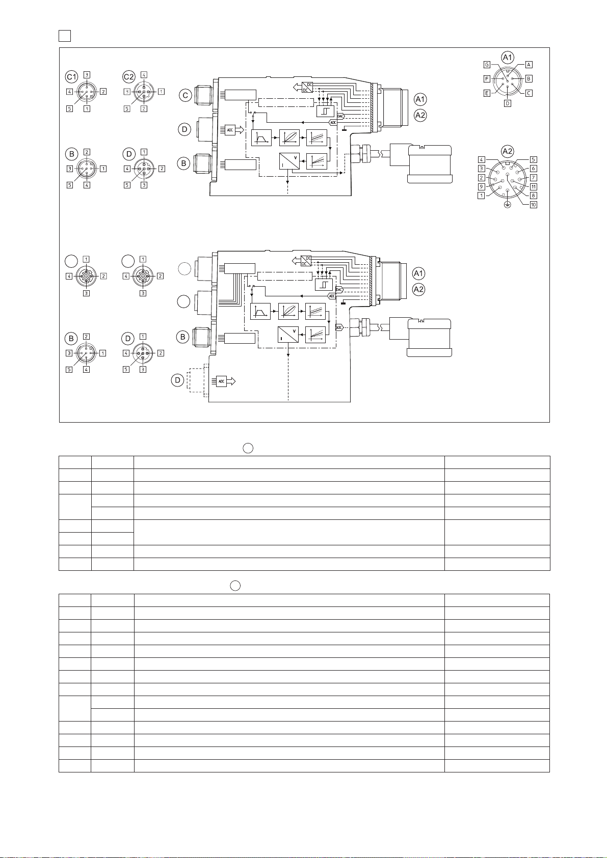
Note: A minimum time of 270 to 340 ms have be considered between the driver energizing with the 24 VDC power supply and when the valve is ready to operate.
During this time the current to the valve coils is switched to zero.
11 CONNECTIONS
DC/DC
CONVERTER
Fieldbus
INTERFACE
MICROCONTROLLER
SCALE
DEAD BANDLINEARIZATIONRAMPS
Serial
INTERFACE
CURRENT TO
SOLENOID S2
(for E-RI-AES-*-05H)
CURRENT TO
SOLENOID S1
COIL CONNECTION
(only for double solenoid valves)
7 PIN MAIN CONNECTOR
Standard and /Q option
(male)
Serial
(male)
PROFIBUS DP
(female)
CANopen
(male)
Analog
pressure
input
(/W option)
12 PIN MAIN CONNECTOR
/Z and /W options
(male)
PRESSURE
TRANSDUCER
/W option
(female)
Serial -PS, CANopen -BC and PROFIBUS DP -BP executions
C3
C3
C4
C4
DC/DC
CONVERTER
EtherCAT
INTERFACE
MICROCONTROLLER
SCALE
DEAD BANDLINEARIZATIONRAMPS
Serial
INTERFACE
CURRENT TO
SOLENOID S2
(for E-RI-AES-EH-05H)
CURRENT TO
SOLENOID S1
COIL CONNECTION
(only for double solenoid valves)
Serial
(male)
EtherCAT
(female - input)
EtherCAT
(female - output)
Analog
pressure
input
(/W option)
Note: Connectors front view
PRESSURE
TRANSDUCER
/W option
(female)
EtherCAT -EH execution
PIN SIGNAL TECHNICAL SPECIFICATIONS NOTES
1 V+ Power supply 24 V
DC for solenoid power stage Input - power supply
2 V0 Power supply 0 V
DC for solenoid power stage Gnd - power supply
3 ENABLE Enable (24 V
DC) or disable (0 VDC) the driver Input - on/off signal
4 INPUT+ Reference analog input: ±10 V
DC / ± 20 mA maximum range software selectable Input - analog signal
5 AGND Ground - signal zero for INPUT+ signal Gnd - analog signal
6 MONITOR Monitor analog output: ±5 V
DC maximum range Output- analog signal
7 NC do not connect
8
NC do not connect (for /Z option)
MONITOR2 2nd monitor analog output: ±5 V
DC maximum range (for /W option) Output - analog signal
9 VL+ Power supply 24 V
DC for driver’s logic and communication Input - power supply
10 VL0 Power supply 0 V
DC for driver’s logic and communication Gnd - power supply
11 FAULT Driver status : Fault (0 V
DC) or normal working (24 VDC) Output- on/off signal
PE EARTH Internally connected to driver housing
PIN SIGNAL TECHNICAL SPECIFICATIONS NOTES
A V+ Power supply 24 VDC for solenoid power stage Input - power supply
B V0 Power supply 0 VDC for solenoid power stage Gnd - power supply
C
AGND Ground - signal zero for MONITOR signal (applying 24 VDC to AGND electronics will damaged) Gnd - analog signal
ENABLE Enable (24 VDC) or disable (0 VDC) the driver (for /Q option) Input - on/off signal
D INPUT+
Reference analog differential input: ±10 VDC / ± 20 mA maximum range software selectable
(see 4.2) - default settings are 0 ÷ 10 V
DC for directional valves 2 positions, pressure or flow
controls and ±10 V
DC for directional valves 3 positions
Input - analog signal
E INPUT -
F MONITOR Monitor analog output: ±5 VDC maximum range Output - analog signal
G EARTH Internally connected to driver housing
11.2 Main connector - 12 pin - /Z and /W options
11.1 Main connector - 7 pin - Standard and /Q option
A1
A2
Page 70
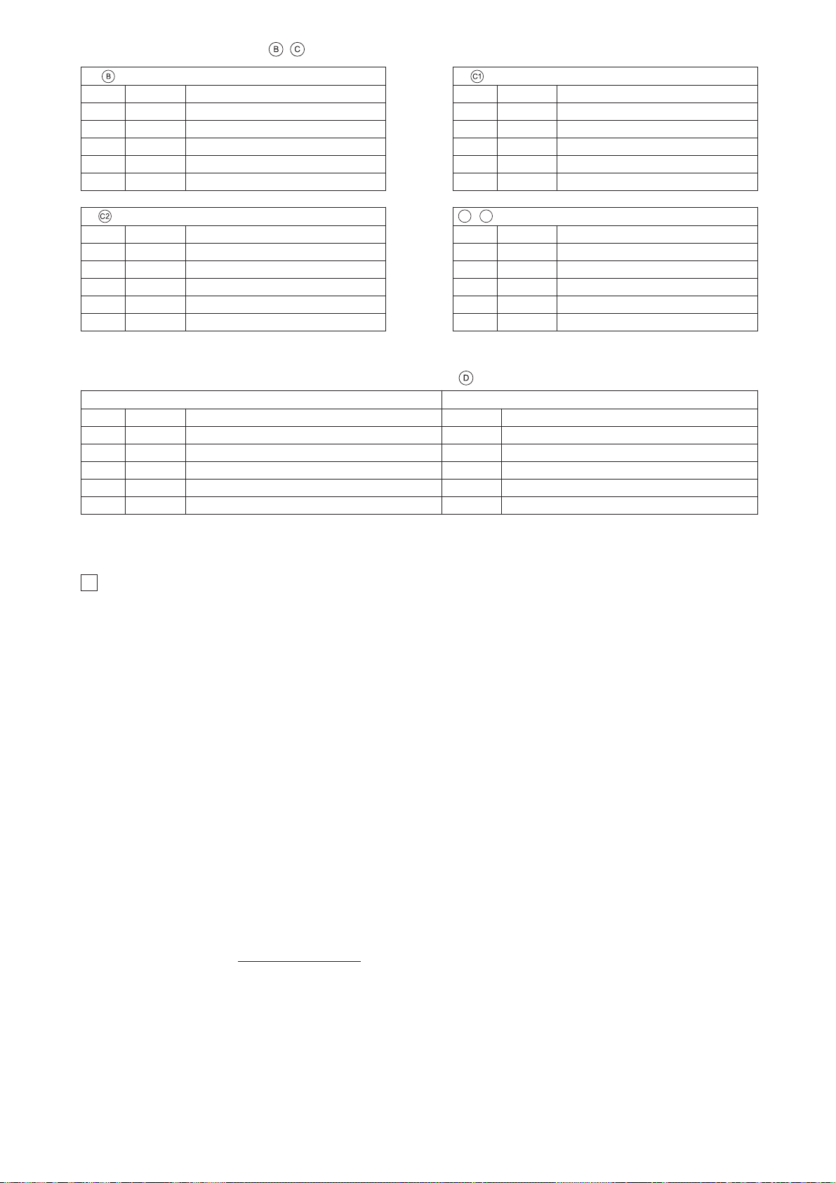
F170
12 DIGITAL INTEGRAL DRIVERS -AES - OPTIONS
Standard driver execution provides on the 7 pin main connector:
Power supply
- 24VDC must be appropriately stabilized or rectified and filtered; a 2,5 A safety fuse is required in series to each driver power supply
Apply at least a 10000 μF/40 V capacitance to single phase rectifiers or a 4700 μF/40 V capacitance to three phase rectifiers.
Reference input signal
- analog differential input with ±10VDC nominal range (pin D,E), proportional to desired coil current (4÷20 mA with cable
break detection, ±10 mA, ±20 mA or 0÷20 mA software selectable)
Monitor output signal
- analog output signal proportional to the actual valve’s coil current (1V monitor = 1A coil current)
Following options are available to adapt standard execution to special application requirements:
12.1 Option /Q - To enable the driver, supply 24Vdc on pin C referred to pin B: when the enable signal is set to zero the valve status is software selectable, by factory default the valve functioning is disabled (zero current to the solenoid) but the driver current output stage is still active. For the complete list of selectable status, see tab. G115.
12.2 Option /Z - It provides, on the 12 pin main connector, the following additional features:
Logic power supply
Separated power supply for the solenoid (pin 1, 2) and for the digital electronic circuits (pin 9, 10).
Cutting solenoid power supply allows to interrupt the valve functioning but keeping energized the digital electronics thus avoiding fault conditions of the
machine fieldbus controller. This condition allows to realize safety systems in compliance with European Norms EN13849-1 (ex EN954-1).
Enable Input Signal
To enable the driver, supply 24Vdc on pin 3 referred to pin 2: when the enable signal is set to zero the valve status is software selectable, by factory default the
valve functioning is disabled (zero current to the solenoid) but the driver current output stage is still active. For the complete list of selectable status, see tab. G115.
Fault Output Signal
Fault output signal indicates fault conditions of the driver (solenoid short circuits/not connected, reference signal cable broken for 4÷20mA input, etc.).
Fault presence corresponds to 0 VDC, normal working corresponds to 24VDC (pin 11 referred to pin 2): Fault status is not affected by the Enable input signal
12.3 Option /W - only for valves coupled with pressure compensator type HC-011 or KC-011 (see tab. D150).
It provides, on the 12 pin main connector, the above option /Z features plus the hydraulic power limitation function.
The driver receives the flow reference signal by the analog external input INPUT+ and a pressure transducer remotely installed in the hydraulic system,
has to be connected to the driver’s analog input TR.
When the actual requested hydraulic power pxQ (TR x INPUT+) reaches the max power limit (p1xQ1), internally set by software, the driver automatically
reduces the flow regulation of the valve. The higher is the pressure feedback the lower is the valve’s regulated flow:
Flow regulation = Min
(
PowerLimit [sw setting]
; Flow Reference [INPUT+]
)
Transducer Pressure [TR]
For detailed information on hydraulic power limitation, see tab. G115
Voltage Input (*) Current Input (*)
PIN SIGNAL TECHNICAL SPECIFICATION SIGNAL TECHNICAL SPECIFICATION
1 VT Remote transducer power supply 24 VDC VT Remote transducer power supply 24 VDC
2 TR Remote transducer signal (0 ÷ 10 VDC) - see 4.7 TR Remote transducer signal (0 ÷ 20 mA) - see 4.7
3 AGND Signal zero for power supply and signal NC do not connect
4 NC do not connect NC do not connect
5 NC do not connect NC do not connect
-BC fieldbus execution - M12 - 5 pin
PIN SIGNAL
TECHNICAL SPECIFICATION (2)
1 CAN_SHLD Shield
2 NC do not connect
3 CAN_GND Signal zero data line
4 CAN_H Bus line (high)
5 CAN_L Bus line (low)
-EH fieldbus execution - M12 - 4 pin
PIN SIGNAL
TECHNICAL SPECIFICATION (2)
1 TX+ Transmitter
2 RX+ Receiver
3 TX Transmitter
4 RX- Receiver
Housing SHIELD
-PS serial execution - M12 - 5 pin (1)
PIN SIGNAL
TECHNICAL SPECIFICATION (2)
1 NC do not connect
2 NC do not connect
3 RS_GND Signal zero data line
4 RS_RX Valves receiving data line
5 RS_TX Valves transmitting data line
11.4 PRESSURE TRANSDUCER CONNECTOR - M12 - 5 pin (only for /W option)
(*) Note: Analog input range is software selectable
11.3 COMMUNICATION CONNECTORS
-BP fieldbus execution - M12 - 5 pin
PIN SIGNAL
TECHNICAL SPECIFICATION (2)
1 +5V Termination supply signal
2 LINE-A Bus line (high)
3 DGND Data line and termination signal zero
4 LINE-B Bus line (low)
5 SHIELD
C3
C4
Note: (1) USB communication not insulated
(2) Shield connection on connector’s housing is recommended
Page 71
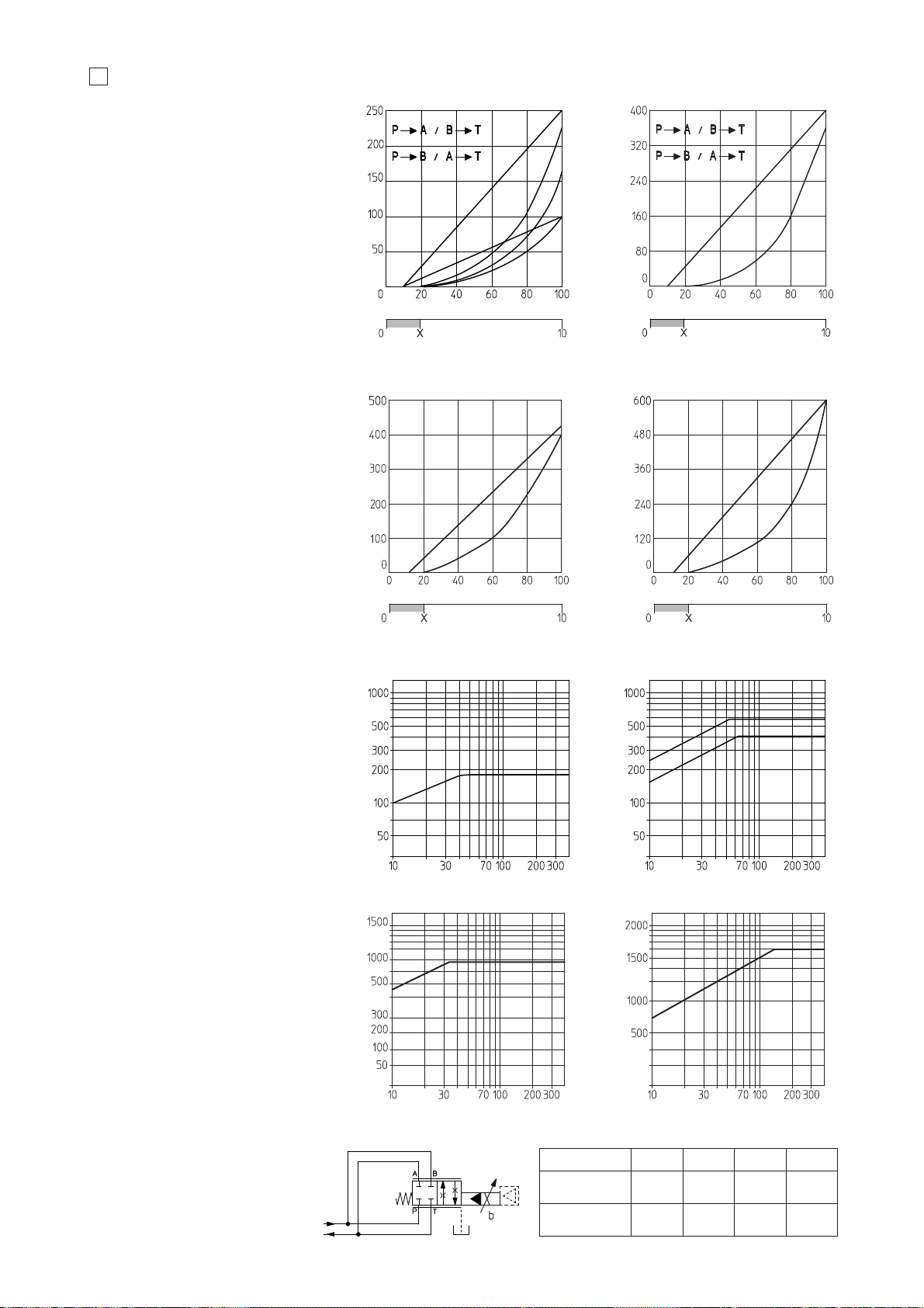
6
7
13
DIAGRAMS (based on mineral oil ISO VG 46 at 50 °C)
13.1 Regulation diagrams
DPZO-1:
1 = linear spool L5
2 = differential spool S5, D5
DPZO-2:
3 = progressive spool S3, D3
4 = progressive spool S5, D5
5 = linear spool L5
DPZO-3:
6 = linear spool L5
7 = progressive spool S5, D5
DPZO-4:
8 = linear spool L5
9 = progressive spool S5, D5
DPZO-6:
10=linear spool L5
11=progressive spool S5, D5
13.2 Flow /Δp diagram
Stated at 100% of valve stroke
DPZO-1:
1 = spool L5, S5, D5
DPZO-2:
2 = spool L5, S5, D5
3 = spool S3, D3
DPZO-4:
4 = spool L5, S5, D5
DPZO-6:
5 = spool L5, S5, D5
Flow rate [l/min]
Valve pressure drop Δp [bar]
Flow rate [l/min]
Valve pressure drop Δp [bar]
1
2
3
4
13.3 Operation as throttle valve
Single solenoid valves (*51) can be
used as simple throttle valves:
Pmax = 250 bar
For this application, the use of valve -T,
-TE or -TES (see tab. F172 and F175) is
advisable (consult our technical office)
Stroke [% of max]
Max flow [l/min] at Δp = 10 bar
X = Threshold for bias activation depending to the valve type and amplifier type
Reference signal [V]Reference signal [V]
Stroke [% of max]
Max flow [l/min] at Δp = 10 bar
1
2
5
4
3
Max flow [l/min]
320 850 2000
151-L5 251-L5 451-L5 651-L5
DPZO-*-
Δp [bar]
30 30
1400
30 30
Note:
Hydraulic configuration vs reference signal for:
- double solenoid valves (standard and option /B)
Reference signal 0 ÷ +10 V
P 촞 A / B 촞 T
12 ÷ 20 mA
Reference signal 0 ÷ -10 V
P 촞 B / A 촞 T
4 ÷ 12 mA
Hydraulic configuration vs reference signal
for single solenoid valves:
Reference signal:
0 ÷ +10 V P 촞 A / B 촞 T (standard)
4 ÷ 20 mA P 촞 B / A 촞 T (option /B)
}
}
}
Max flow [l/min] at Δp = 10 bar
Stroke [% of max]
11
10
Reference signal [V]
Max flow [l/min] at Δp = 10 bar
Stroke [% of max]
9
8
Reference signal [V]
Flow rate [l/min]
Valve pressure drop Δp [bar]
5
Flow rate [l/min]
Valve pressure drop Δp [bar]
Page 72
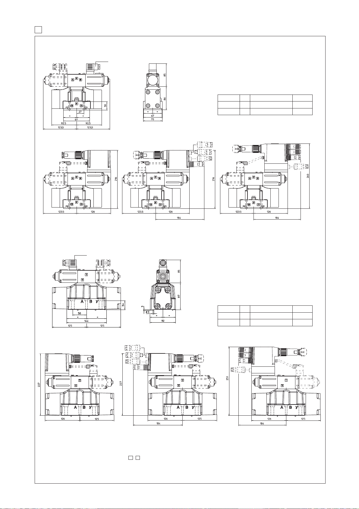
14 INSTALLATION DIMENSIONS FOR DPZO-1 AND DPZO-2 [mm]
DPZO-A(*)-1
ISO 4401: 2005
Mounting surface: 4401-05-05-0-05 (see table P005)
Fastening bolts:
4 socket head screws M6x40 class 12.9
Tightening torque = 15 Nm
Seals: 5 OR 2050; 2 OR 108
Diameter of ports A, B, P, T: Ø = 11 mm;
Diameter of ports X, Y: Ø = 5 mm;
DPZO-A(*)-2
ISO 4401: 2005
Mounting surface: 4401-07-07-0-05 (see table P005)
Fastening bolts:
4 socket head screws M10x50 class 12.9
Tightening torque = 70 Nm
2 socket head screws M6x45 class 12.9
Tightening torque = 15 Nm
Seals: 4 OR 130; 3 OR 109/70
Diameter of ports A, B, P, T: Ø = 20 mm;
Diameter of ports X, Y: Ø = 7 mm;
Mass [kg]
DPZO-*-15*
7,7
A AE, AES, AEG, AEZ AES-EH
8,6
8,1
9
8,2
9,1
DPZO-*-17*
Mass [kg]
DPZO-*-25*
11,9
A AE, AES, AEG, AEZ AES-EH
12,8
12,3
13,2
12,4
13,3
DPZO-*-27*
DPZO-A-1
DPZO-AE-1
DPZO-AES-1
DPZO-A-2
DPZO-AE-2 DPZO-AES-2
(dotted line = double solenoid version)
666
For main and communication connector see section ,
18 19
NOTE: The overall height is increased by 40 mm for /G option (0,9 kg).
For option /B the proportional solenoid and the electronics (in case of execution -AE and -AES) are at side of port B of the main stage.
666
(dotted line = double solenoid version)
DPZO-AES-EH-2
DPZO-AES-EH-1
F170
Page 73
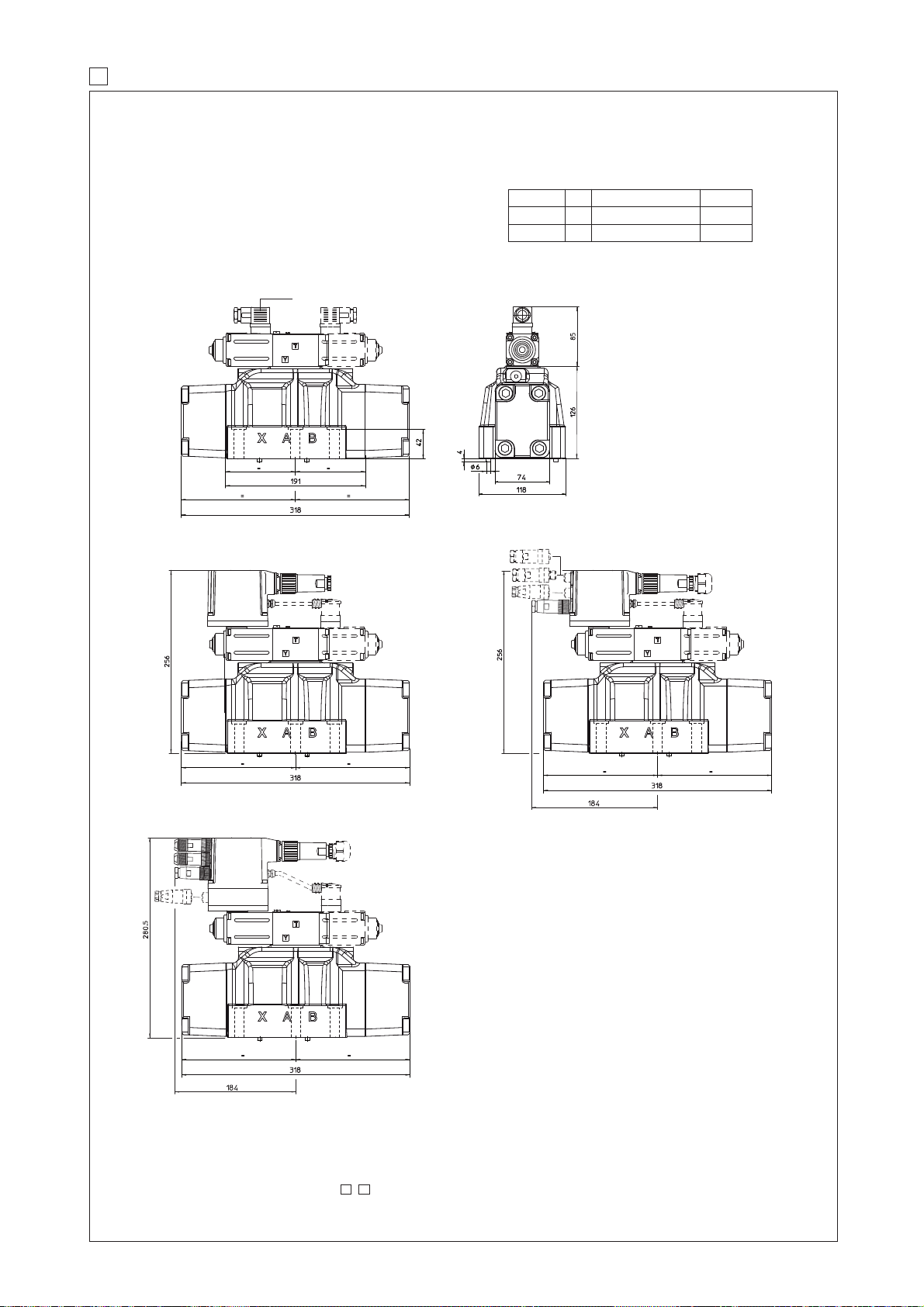
15 INSTALLATION DIMENSIONS FOR DPZO-4 [mm]
DPZO-A(*)-4
(dotted line = double solenoid version)
DPZO-A-4
DPZO-AE-4
DPZO-AES-4
666
ISO 4401: 2005
Mounting surface: 4401-08-08-0-05 (see table P005)
Fastening bolts:
6 socket head screws M12x60 class 12.9
Tightening torque = 125 Nm
Seals: 4 OR 4112; 2 OR 3056
Diameter of ports A, B, P, T: Ø = 24 mm;
Diameter of ports X, Y: Ø = 7 mm;
DPZO-AES-EH-4
NOTE: The overall height is increased by 30 mm for /G option (0,9 kg).
For option /B the proportional solenoid and the electronics (in case of execution -AE and -AES) are at side of port B of the main stage.
Mass [kg]
DPZO-*-45*
17,1
A AE, AES, AEG, AEZ AES-EH
18
18
18,9
18,1
19
DPZO-*-47*
For main and communication connector see section ,
18 19
Page 74
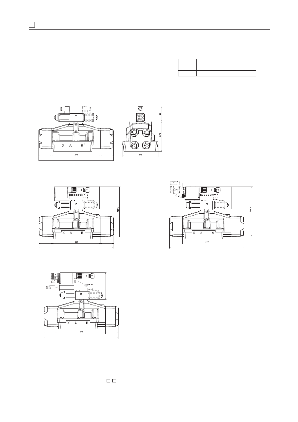
16 INSTALLATION DIMENSIONS FOR DPZO-6 [mm]
DPZO-A(*)-6
435
130
8080
435
80 80
435
130
80 80
435
DPZO-A-6
DPZO-AE-6 DPZO-AES-6
666
(dotted line = double solenoid version)
80 80
435
154
DPZO-AES-EH-6
NOTE: The overall height is increased by 40 mm for /G option (0,9 kg).
For option /B the proportional solenoid and the electronics (in case of execution -AE and -AES) are at side of port B of the main stage.
Mass [kg]
DPZO-*-65*
42,1
A AE, AES, AEG, AEZ
42,7
42,5
43,1
AES-EH
42,6
43,2
DPZO-*-67*
ISO 4401: 2005
Mounting surface:
4401-10-09-0-05
Fastening bolts:
6 socket head screws M20x90 class 12.9
Tightening torque = 600 Nm
Diameter of ports A, B, P, T: Ø = 34 mm;
Diameter of ports X, Y: Ø = 7 mm;
Seals: 4 OR 144, 3 OR 3056
For main and communication connector see section ,
18 19
F170
Page 75
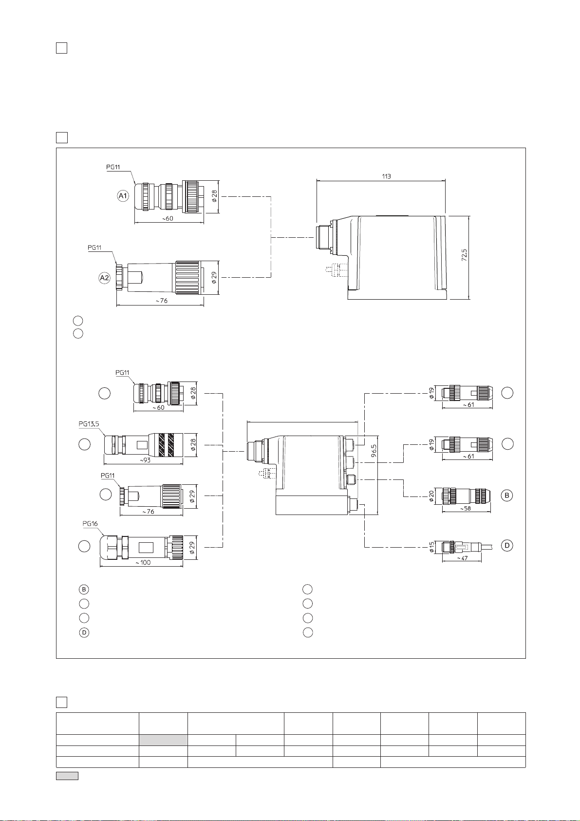
MODEL CODES OF POWER SUPPLY AND COMMUNICATION CONNECTORS (to be ordered separately)
19
666
connectors supplyed with the valve
VALVE VERSION
CONNECTOR CODE
ZH-7P ZM-7P ZH-12P ZH-5P ZH-5P/BP ZM-4PM/EH
PROTECTION DEGREE
IP65 IP67 IP67 IP67 IP67 IP67
-A -AE, -AES -AES/Z CANopen (-BC)
PROFIBUS DP
(-BP)
IP67
EtherCAT (-EH)
DATA SHEET
K500 G110, G115, K500
G115, K500
ZH-5PM
IP67
-AES/W
-AEZ
G115, K500
CONNECTORS
18
03/15
ZM-7P
ZH-7P
Main connector (Plastic)
Main connector (Metallic)
A1
A2
E-RI-AE-**
ZM-7P
ZH-12P
ZM-12P
128 mm for 7 pin standard and /Q option
137 mm for 12 pin /Z and /W options
ZM-4PM/EH
ZM-4PM/EH
ZH-5PM
ZH-5P
Main connector - 7 pin (Plastic)
Main connector - 12 pin (Plastic)
A1
A2
Main connector - 7 pin (Metallic)
A3
Input EtherCAT communication connector (-EH)
Output EtherCAT communication connector (-EH)
C3
C4
Pressure transducer connector (/W option)
Serial communication connector
Main connector - 12 pin (Metallic)
A4
ZH-7P
EtherCAT -EH execution
A1
A2A3A4
C3
C4
Valve's functional parameters and configurations, can be easily set and optimized using Atos E-SW programming software connected to the digital driver.
E-SW software is available in different versions according to the driver’s communication interface: PS (Serial) E-SW-PS, BC (CANopen) E-SW-BC, BP
(PROFIBUS DP) and EH (EtherCAT). Proportional valves with fieldbus communication interface can be directly managed by the machine control unit; it is
required to implement in the machine control the standard communication as described in the user manuals supplied with the relevant programming
software.
PROGRAMMING TOOLS - see tech table GS500
17
Page 76
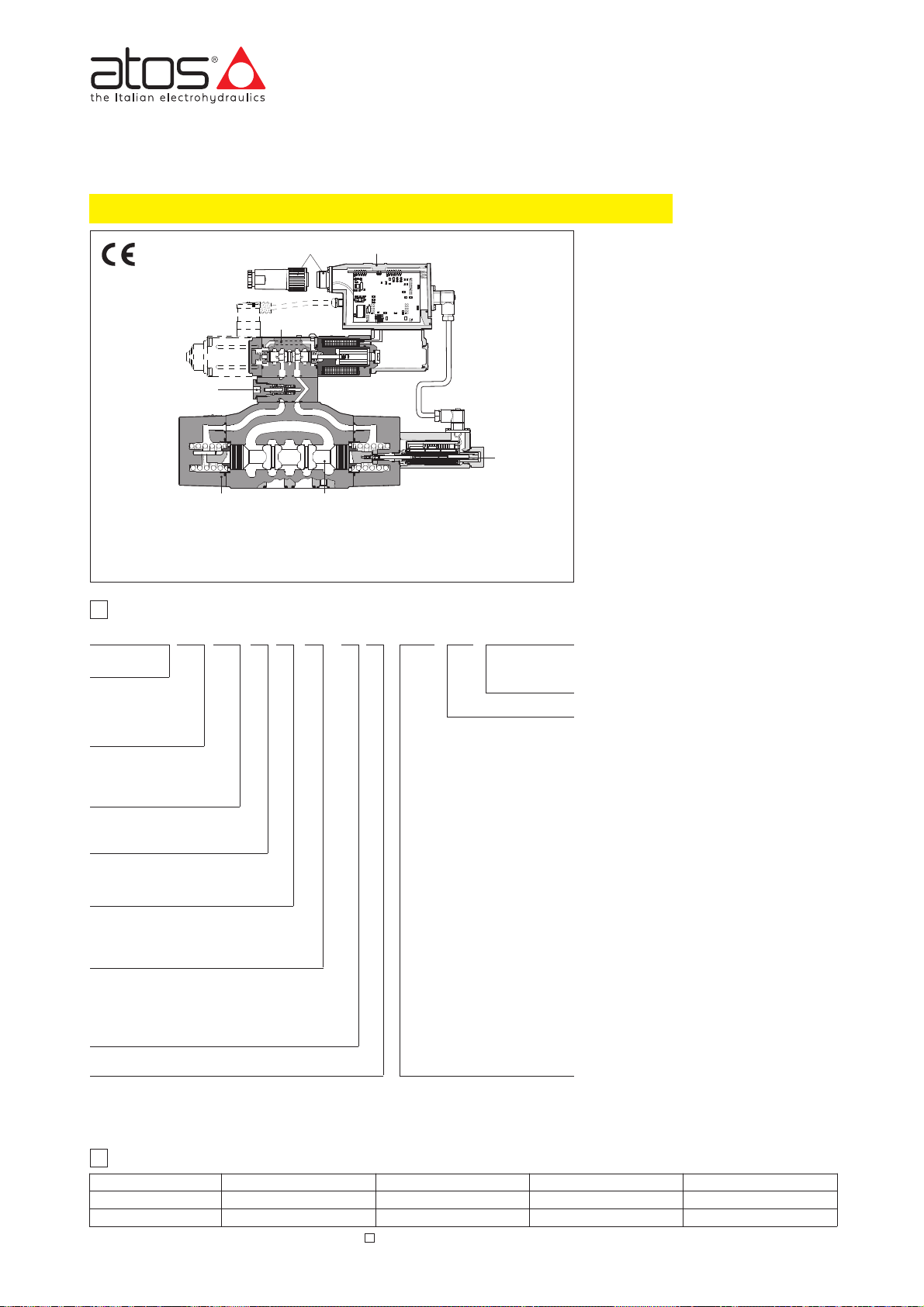
Proportional directional valves type DPZO-TE
two stage, with position transducer, ISO 4401 sizes 10, 16, 25 and 32
A
B
Pressure reducing valve
Integral electronics
Main connector
Valve body
Main stage Spool
Pilot valve
Main stage position transducer
www.atos.com
Table F172-9/E
F172
Series
number
DPZO
Piloted proportional
directional valve
Valve size:
1 = 10; 2 = 16;
4 = 25; 6 = 32;
Spool overlapping in central position
, see section
쪩
1 = P, A, B, T with positive overlapping (1)
3 =
P positive overlapping (1); A, B, T, negative overlapping
Spool size: 3, 5, 9 see section
쪩
TES PS
27 –1L5/ /***/ *–––
1
MODEL CODE
Hydraulic options, see section쪪:
B =solenoid, integral electronics and
position transducer at side of port A
of the main sta
ge (side B of pilot valve)
E =external pilot (through port X)
D =internal drain
Electronic options for -TE execution
see section
쪭
:
F = fault signal
I =current reference input and monitor
(4÷20 mA)
Q =enable signal
Z = enable, fault and monitor signal (12
pin connector)
Electronic options
for -TES execution
see section쪯:
I =current reference input and monitor
(4÷20 mA)
Z = double power supply, enable, fault and
monitor signals
(12 pin connector)
Special options
for -TES execution
see
section
쪯
:
SF =
additional closed loop force control,
with two remote pressure tran-
sducers
SL = additional closed loop force con-
trol
with one remote load cell
SP = additional closed loop pressure
control with one remote pressure
transducer
C =
current feedback interface for transducer(s) only for options /SF, /SL, /SP
Communication interfaces (only for TES)
PS = RS232 serial
BC = CANbus
BP = PROFIBUS-DP
Configuration, see section
쪩
5 =
external plus central position, spring centered
7 = 3 position, spring centered
2
ELECTRONIC DRIVERS
Spool type (regulating characteristics):
L = linear;
S = progressive;
D =
differential-progressive
(as S, but with P-A = Q, P-B = Q/2)
DL =
differential-linear
(as L, but with P-A = Q, P-B = Q/2)
DPZO-T* are two stage proportional valves with position transducer on the main
spool which provide both directional and
non compensated flow control according
to electronic reference signal.
They operate in association with electronic drivers, see section
쪨
, which supply
the proportional valves with proper current to align valve regulation to the reference signal supplied to the electronic
driver.
They are available in different executions:
• -T, with position transducers ;
• -TE, -TES as -T plus analog (TE) or
digital (TES) integral electronics .
The 4-way spool , sliding into a
5-chambers body , is piloted by a
proportional directional valve type
DHZO (see tab. F160) and it is controlled
in closed loop position by means of the
LVDT transducer .
The pressure reducing valve with fixed
setting ensures a costant piloting
pressure.
The integral electronics ensures
factory presetting, fine functionality
plus valve-to-valve interchangeability
and simplified wiring and installation.
The electronic main connector is fully
interchangeable for –TE and –TES
executions.
Standard 7 pin main connector is used
for power supply, analog input reference
and monitor signals.
12 pin connector is used for options /Z
and /S*.
The special /S* options add a closed
loop control of pressure (/SP) or force
(/SF and /SL) to the basic closed loop
spool position one.
Following communication interfaces
are available for the digital -TES
execution:
• -PS, Serial communication interface for
configuration, monitoring and firmware
updating through Atos PC software
•
-BC, CANopen interface
• -BP, PROFIBUS DP interface
The valves with -BC and -BP interfaces
can be integrated into a fieldbus
communication network and thus digitally
operated by the machine control unit.
The coils are fully plastic encapsulated
(insulation class H) and the valves have
antivibration, antishock and weather-proof
features.
Mounting surface: ISO 4401 sizes 10, 16,
25 and 32.
Max flow respectively up to 160 l/min, 430
l/min, 830 l/min and 1100 l/min with valve
differential pressure Δp = 30 bar, see
table 쪨.
Max pressure: 350 bar.
Note: For power supply and communication connector see section 17
Notes:
(1) Overlapping = 20% of spool stroke for type S, D and Q; 10% of spool stroke for type L and DL
Valve model
Data sheet
Drivers model E-ME-T
G140
-T
E-RI-TE
G200
-TE
E-RI-TES
G210
-TES
E-RI-TES/SF, /SL, /SP
G212
-TES / SF, SL, SP
Seals material:
omit for NBR (mineral
oil & water glycol)
PE = FPM
T =
with position transducer
TE = as T with integral
analog electronics
TES = with digital electronics
DPZO-TE-251
DPZO-TE-271
(dotted line)
TE and TES executions included in this table are available only for running supplies or spare parts
For new applications it is suggested new TEB and TES executions, see table FS172
Page 77
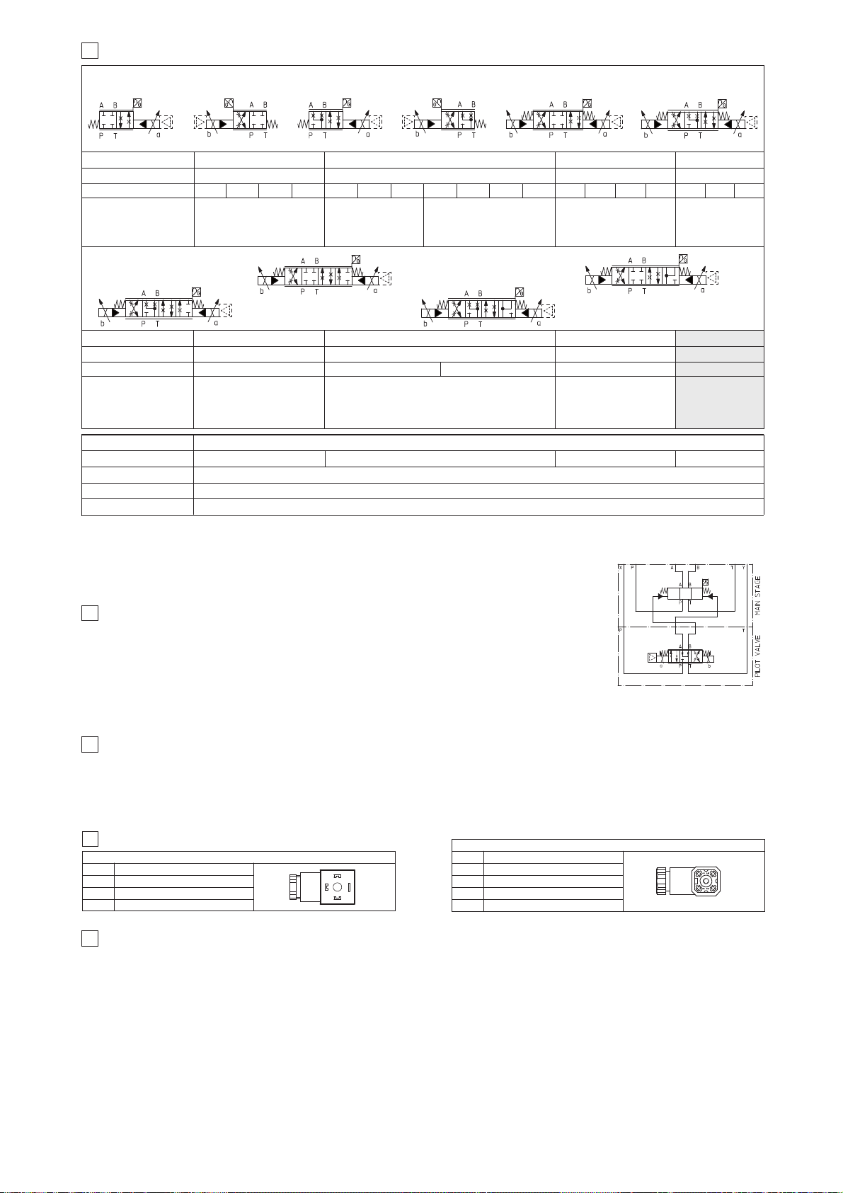
4
HYDRAULIC OPTIONS
4.1 Option /B DPZO-*-*5 = solenoid, integral and position transducer at side of port A of the main stage.
DPZO-*-*7 = integral electronics and position transducer at side of port A of the main stage.
For hydraulic configuration vs. reference signal, see section 13.1
4.2 Pilot and drain configuration -The pilot/drain configuration can be modified as shown in the table
E085 section 10.
The valve’s standard configuration provides internal pilot and external drain. For different pilot / drain
configuration select: Option /E External pilot (through port X). Option /D Internal drain.
Signal description
OUTPUT SIGNAL
SUPPLY -15 V
DC
SUPPLY +15 VDC
GND
PIN
1
2
3
4
POSITION TRANSDUCER CONNECTOR
6
CONNECTIONS FOR -T EXECUTION
Signal description
SUPPLY
SUPPLY
GND
PIN
1
2
3
SOLENOID POWER SUPPLY CONNECTOR
1
2
3
1
2
3
4
Standard driver execution provides on the 7 pin main connector:
Power supply
- 24VDC must be appropriately stabilized or rectified and filtered; a 2,5 A safety fuse is required in series to the driver power supply
Apply at least a 10000 μF/40 V capacitance to single phase rectifiers or a 4700 μF/40 V capacitance to three phase rectifiers
Reference input signal
- analog differential input with ±10 VDC nominal range (pin D,E), proportional to desired valve spool position
Monitor output signal
- analog output signal proportional to the actual valve’s spool position with ±10 VDC nominal range
Following options are available to adapt standard execution to special application requirements:
7.1 Option /F It provides a Fault output signal in place of the Monitor output signal, to indicate fault conditions of the driver (cable interruption of spool
transducers or reference signal - for /I option): Fault presence corresponds to 0 V
DC, normal working corresponds to 24 VDC.
7.2 Option /I It provides the 4÷20 mA current reference and monitor signals instead of the standard ±10 V
DC
It is normally used in case of long distance between the machine control unit and the valve or where the reference signal can be
affected by electrical noise; the valve functioning is disabled in case of reference signal cable breakage.
7.3 Option /Q It provides the possibility to enable or disable the valve functioning without cutting the power supply (the valve functioning is disabled
but the driver current output stage is still active). To enable the driver supply a 24V
DC on the enable input signal.
7.4 Option /Z
This option includes /F and /Q features, plus the Monitor output signal.
When the driver is disabled (
0 VDC
on Enable signal) Fault output is forced to 0
VDC
.
7.5 Possible combined options: /FI and /IZ
7 ANALOG INTEGRAL DRIVERS -TE - OPTIONS
DPZO-T* proportional valves are CE marked according to the applicable Directives (e.g. Immunity/Emission EMC Directive and Low Voltage Directive).
Installation, wirings and start-up procedures must be performed according to the general prescriptions shown in table F003 and in the installation notes
supplied with relevant components.
The electrical signals of the valve (e.g. monitor signals) must not be directly used to activate safety functions, like to switch-ON/OFF the machine’s safety
components, as prescribed by the European standards (Safety requirements of fluid technology systems and components-hydraulics, EN-982).
5
GENERAL NOTES
480
830
1000
L5 DL5
1, 3
D3 D5
DL5
100
160
180
1, 3
L5 S5
160
270
400
1, 3
L3 S3
250
430
550
L5 S5D5
DL5
3
HYDRAULIC CHARACTERISTICS OF STANDARD SPOOL (based on mineral oil ISO VG 46 at 50 °C) (3)
Valve model
Spool overlapping
Spool type and size
Max flow (1): [l/min]
at Δp = 10 bar
at Δp = 30 bar
max permissible flow
Standard spools - hydraulic symbols
Valve model
Spool overlapping
Spool type and size
Max flow
(1)
: [l/min]
at Δp = 10 bar
at Δp = 30 bar
max permissible flow
Specific spools hydraulic symbols
Response time
(3) [ms]
Hysteresis [%]
Repeatability
Thermal drift
zero point displacement < 1% at ΔT = 40°C
Pressure limits
(2) [bar]
ports P, A, B, X = 350; T = 250 (10 for option /D); Y = 10
DPZO-T*-4 DPZO-T*-6
DPZO-T*-2
DPZO-T*-1
Notes:
Above performance data refer to valves coupled with Atos electronic drivers, see section 쪨.
In case of long time shutdown of the hydraulic supply to the pilot valve, the driver has to be switched off to avoid
its overheating.
(1) For different
Δ
p, the max flow is in accordance to the diagrams in section 13.2
(2) Minimum piloting pressure = 25 bar
(3) 0-100% step signal
1, 3
D9
100:60
160:100
180:110
D9
L9
DPZO-T*-2DPZO-T*-1
250
430
550
1, 3
≤ 0,1%
±0,5%
< 60
< 80 < 120
< 75
DPZO-T*-4
S5
640
1100
1600
L5 D5
1, 3
*51
*53
*71
*73
*51/B
*53/B
*73-D9
*71-D9
*71-L9
*73-L9
FUNCTIONAL SCHEME
example of configuration 7
(3 positions, spring centered)
480
830
1000
D9
1, 3
S5 D5
102
Page 78
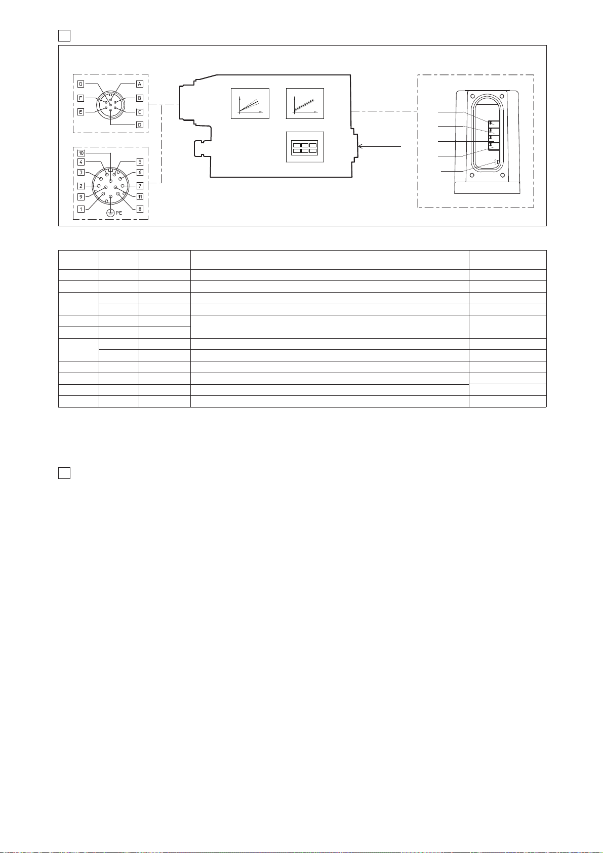
9 DIGITAL INTEGRAL DRIVERS -TES - OPTIONS
8 ANALOG INTEGRAL DRIVERS -TE - MAIN FUNCTIONS AND ELECTRONIC CONNECTIONS
12 PIN - OPTION /Z
REGULATIONS AND LED
7 PIN - STANDARD
MAIN CONNECTOR
BIAS
SCALE
DIAGNOSTIC
Standard
7pin
/Z option
12pin
SIGNAL
TECHNICAL SPECIFICATIONS
NOTES
A 1 V+ Power supply 24 VDC for solenoid power stage and driver logic
Input - power supply
Gnd - power supply
B 2 V0 Power supply 0 VDC for solenoid power stage and driver logic
C
(1)
7 AGND Ground - signal zero for MONITOR signal (for standard, /Z option) Input - analog signal
3 ENABLE Enable (24 VDC) or disable (0 VDC) the driver (for /Q and /Z options) Input - on/off signal
D 4 INPUT+
Reference analog differential input: ±10 VDCmaximum range (4 ÷ 20 mA for /I option)
For single solenoid valves the reference input is 0÷+10 V
DC
(4 ÷ 20 mA for /I option)
For double solenoid valves the reference input is ±10 V
DC
(4 ÷ 20 mA for /I option)
Input - analog signal
E 5 INPUT -
F
(2)
6 MONITOR Monitor analog output: ±10 VDC maximum range; (4 ÷ 20 mA for /I option) Output - analog signal
11 FAULT Fault (0V) or normal working (24V) (for /F and /Z option) Output - on/off signal
- 8 R_ENABLE Repeat Enable - output repetition of Enable input Output - on/off signal
- 9 NC do not connect
Output - on/off signal
Output - on/off signal
- 10 NC
do not connect
G PE EARTH Internally connected to the driver housing
Notes:
(1) with /Q option ENABLE signal replaces AGND on pin C; MONITOR signal is reffered to pin B
(2) with /F option FAULT signal replaces MONITOR on pin F.
A minimum time of 50ms to 100ms have be considered between the driver energizing with the 24 VDC power supply and when the valve is ready to operate.
During this time the current to the valve coils is switched to zero.
B2
B1
S2
S1
positive bias adjust
LED:
쩨
쩨
쩨
쩨
LED
쩨
(driver side)
(driver side)
8.1 ELECTRONIC CONNECTIONS - 7 & 12 PIN MAIN CONNECTORS
negative bias adjust (only for
single solenoid valves
)
positive scale adjust
negative scale adjust (only for
double solenoid valves
)
OFF normal working; ON fault presence
B1:
B2:
S1:
S2:
(remove the rear cover)
Standard driver execution provides on the 7 pin main connector:
Power supply
- 24VDC must be appropriately stabilized or rectified and filtered; a 2,5 A safety fuse is required in series to each driver power supply
Apply at least a 10000 μF/40 V capacitance to single phase rectifiers or a 4700 μF/40 V capacitance to three phase rectifiers
Reference input signal
- analog differential input with ±10VDC nominal range (pin D,E), proportional to desired valve spool position
Monitor output signal
- analog output signal proportional to the actual valve’s spool position with ±10VDC nominal range
Following options are available to adapt standard execution to application requirements:
9.1 Option /I
It provides 4÷20 mA current reference and monitor signals instead of the standard ±10 V.
It is normally used in case of long distance between the machine control unit and the valve or where the reference signal can be affected by electrical
noise; the valve functioning is disabled in case of reference signal cable breakage.
9.2 Option /Z
It provides, on the 12 pin main connector, the following additional features:
Logic power supply
Separated power supply for the solenoid (pin 1, 2) and for the digital electronic circuits (pin 9, 10).
Cutting solenoid power supply allows to interrupt the valve functioning but keeping energized the digital electronics thus avoiding fault conditions of the
machine fieldbus controller. This condition allows to realize safety systems in compliance with European Norms EN13849-1 (ex EN954-1).
Enable Input Signal
To enable the driver, supply 24V
DC on pin 3 referred to pin 2: when the Enable signal is set to zero the valve functioning is disabled (zero current to the
solenoid) but the driver current output stage is still active.
Fault Output Signal
Fault output signal indicates fault conditions of the driver (solenoid short circuits/not connected, reference signal cable broken for 4÷20mA input, etc.).
Fault presence corresponds to 0
VDC
, normal working corresponds to 24
VDC (pin 11 referred to pin 2)
: Fault status is not affected by the Enable input signal
9.3 Options /SP, /SF and /SL
These options add the closed loop control of pressure (/SP) or force (/SF and /SL) to the basic functions of proportional directional valves: a dedicated
software alternates pressure (force) and valve’s spool position controls depending on the actual hydraulic system conditions.
A dedicated connector is available for the additional transducers that are required to be interfaced to the valve’s driver (1 pressure transducer for /SP,
2 pressure transducers for /SF or 1 load cell for /SL).
Main 12 pin connector is the same as /Z option plus two analog signals specific for the pressure (force) control: one for reference (pin 7) and one for
monitor (pin 8).
For futher details please refer to the driver technical table G212.
9.4 Options /C
Options /CSP, /CSF and /CSL are available to connect pressure (force) transducers with 4 ÷ 20mA current output signal.
9.5 Possible combined options: /ISF, /ISL, /ISP, /CSP, /CSF, /CSL, /CISP, /CISF, /CISL and /IZ
SPOOL POSITION
SIGNAL
(main stage)
F172
CURRENT
TO COIL S2
(Only for double
solenoid valves)
Page 79
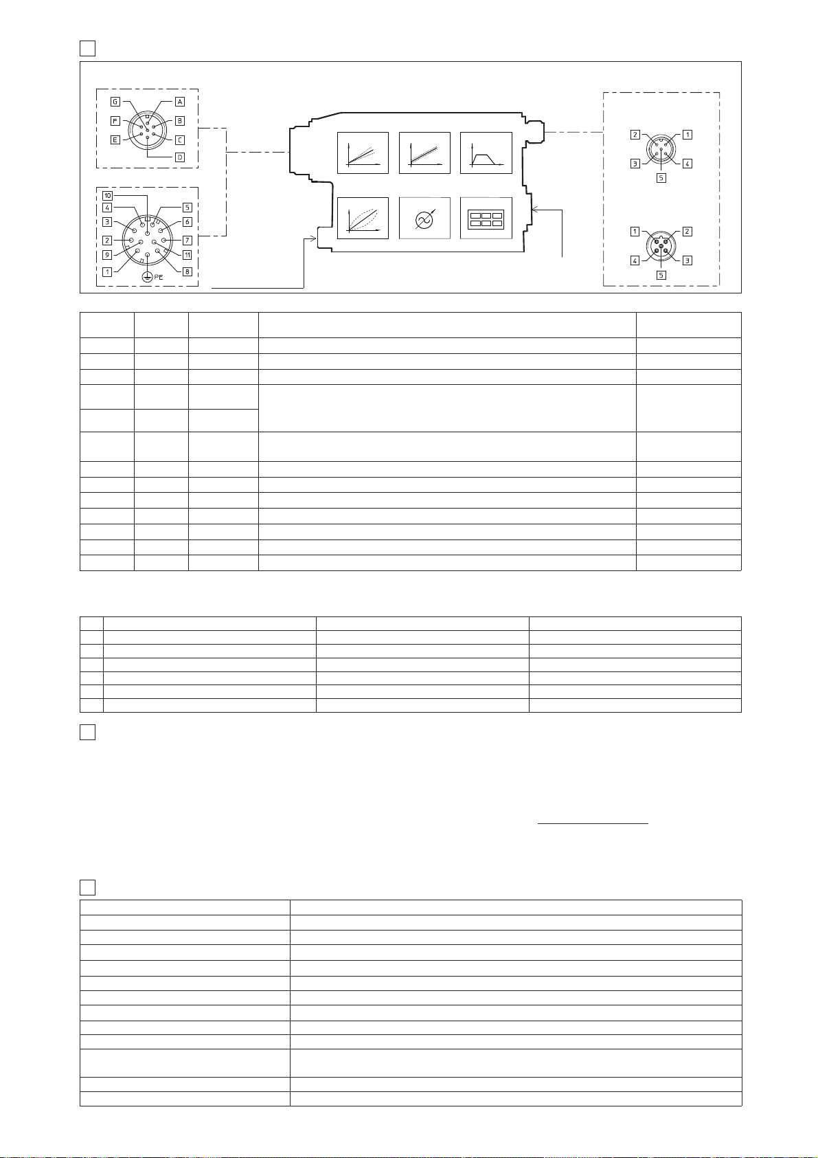
10.2 ELECTRONIC CONNECTIONS - 5 PIN COMMUNICATION CONNECTORS
10.1 ELECTRONIC CONNECTIONS - 7 & 12 PIN MAIN CONNECTORS
-PS Serial -BC CANopen -BP PROFIBUS DP
PIN SIGNAL TECHNICAL SPECIFICATION SIGNAL TECHNICAL SPECIFICATION SIGNAL TECHNICAL SPECIFICATION
1 NC do not connect CAN_SHLD Shield +5V for termination
2 NC do not connect NC do not connect LINE-A Bus line (high)
3 RS_GND Signal zero data line CAN_GND Signal zero data line DGND data line and termination Signal zero
4 RS_RX Valves receiving data line CAN_H Bus line (high) LINE-B Bus line (low)
5 RS_TX Valves transmitting data line CAN_L Bus line (low) SHIELD
Standard
7pin
/Z option
12pin
SIGNAL TECHNICAL SPECIFICATIONS NOTES
A 1 V+
Power supply 24 VDC for solenoid power stage (and for driver logic on 7 pin connection)
Input - power supply
Gnd - power supply
B 2 V0 Power supply 0 VDC for solenoid power stage (and for driver logic on 7 pin connection)
- 3 ENABLE Enable (24 VDC) or disable (0 VDC) the driver Input - on/off signal
D 4 INPUT+
Reference analog input: ±10 VDC maximum range (4 ÷ 20 mA for /I option)
For single solenoid valves the reference input is 0÷+10 V
DC (4 ÷ 20 mA for /I option)
For double solenoid valves the reference input is ±10 V
DC (4 ÷ 20 mA for /I option)
standard: differential input; /Z option: common mode INPUT+ referred to AGND
Input - analog signal
E - INPUT -
C 5 AGND
Ground - signal zero for MONITOR signal
signal zero for INPUT+ signal (only for /Z option)
Gnd - analog signal
F 6 MONITOR Monitor analog output: ±10 VDC maximum range; (4 ÷ 20 mA for /I option) Output - analog signal
- 7 NC do not connect (pressure/force input for /SP, /SF and /SL options, see 9.3)
- 8 NC do not connect (pressure/force monitor for /SP, /SF and /SL options, see 9.3)
- 9 VL+ Power supply 24 VDC for driver logic
Input - power supply
Gnd - power supply
- 10 VL0 Power supply 0 VDC for driver logic
- 11 FAULT Fault (0V) or normal working (24V) Output - on/off signal
G PE EARTH Internally connected to the driver housing
10 DIGITAL INTEGRAL DRIVERS -TES - MAIN FUNCTIONS AND ELECTRONIC CONNECTIONS
COMMUNICATION
CONNECTOR
12 PIN - OPTION /Z, /SP, /SF and /SL
7 PIN - STANDARD
5 PIN reverse key
PROFIBUS DP (-BP)
5 PIN
Serial (-PS) or
CANopen (-BC)
RAMPSBIASSCALE
LINEARIZATION
FIELDBUS
REFERENCE
ENHANCED
DIAGNOSTIC
CONNECTOR FOR
REMOTE PRESSURE
(FORCE) TRANDUCER
(for /SP, /SF and /SL)
11
SOFTWARE TOOLS
MAIN CONNECTOR
Note: A minimum time of 300 to 500 ms have be considered between the driver energizing with the 24 V
DC power supply and when the valve is ready
to operate. During this time the current to the valve coils is switched to zero.
(driver side)
(driver side)
(driver side)
Assembly position Any position
Subplate surface finishing Roughness index Ra 0,4 - flatness ratio 0,01/100 (ISO 1101)
Ambient temperature -20°C ÷ +70°C for -T execution; -20°C ÷ +60°C for -TE and -TES executions
Fluid Hydraulic oil as per DIN 51524 ... 535 for other fluids see section
쪧
Recommended viscosity 15 ÷100 mm2/s at 40°C (ISO VG 15÷100)
Fluid contamination class ISO 4406 class 20/18/15 NAS 1638 class 9, in line filters of 10 μm (β
10 _>75 recommended)
Fluid temperature -20°C +60°C (standard seals) -20°C +80°C (/PE seals)
12
MAIN CHARACTERISTICS OF PROPORTIONAL DIRECTIONAL VALVES
Coil resistance R at 20°C 3 ÷ 3,3 Ω
Max. solenoid current 2,6 A
Max. power 35 Watt
Insulation class H (180°) Due to the occuring surface temperatures of the solenoid coils, the European standards
ISO 13732-1 and EN982 must be taken into account
Protection degree (CEI EN-60529)
IP65 for -T execution; IP67 for -TE and -TES executions
Duty factor Continuous rating (ED=100%)
SPOOL POSITION
SIGNAL
(main stage)
The driver configuration and parameters can be easily set with the Atos E-SW programming software, available in three different versions according to the
driver’s communication execution: E-SW-PS (Serial), E-SW-BC (CANopen) and E-SW-BP (PROFIBUS DP).
For a more detailed description of software interface, PC requirements, adapters, cables and terminators, please refer to technical table G500.
Programming software, must be ordered separately:
E-SW-* (mandatory - first supply) = Dvd including E-SW-* software installer and operator manuals; it allows the registration to Atos digital service
E-SW-*-N (optional - next supplies) = as above but not allowing the registration to Atos digital service
On first supply of the E-SW-* software, it is required to apply for the registration in the Atos download area: www.download.atos.com.
Once the registration is completed, the password will be sent by email.
The software remains active for 10 days from the installation date and then it stops until the user inputs his password.
With the password you can also download, in your personal area, the latest releases of the Atos software, manuals, drivers and configuration files.
Page 80
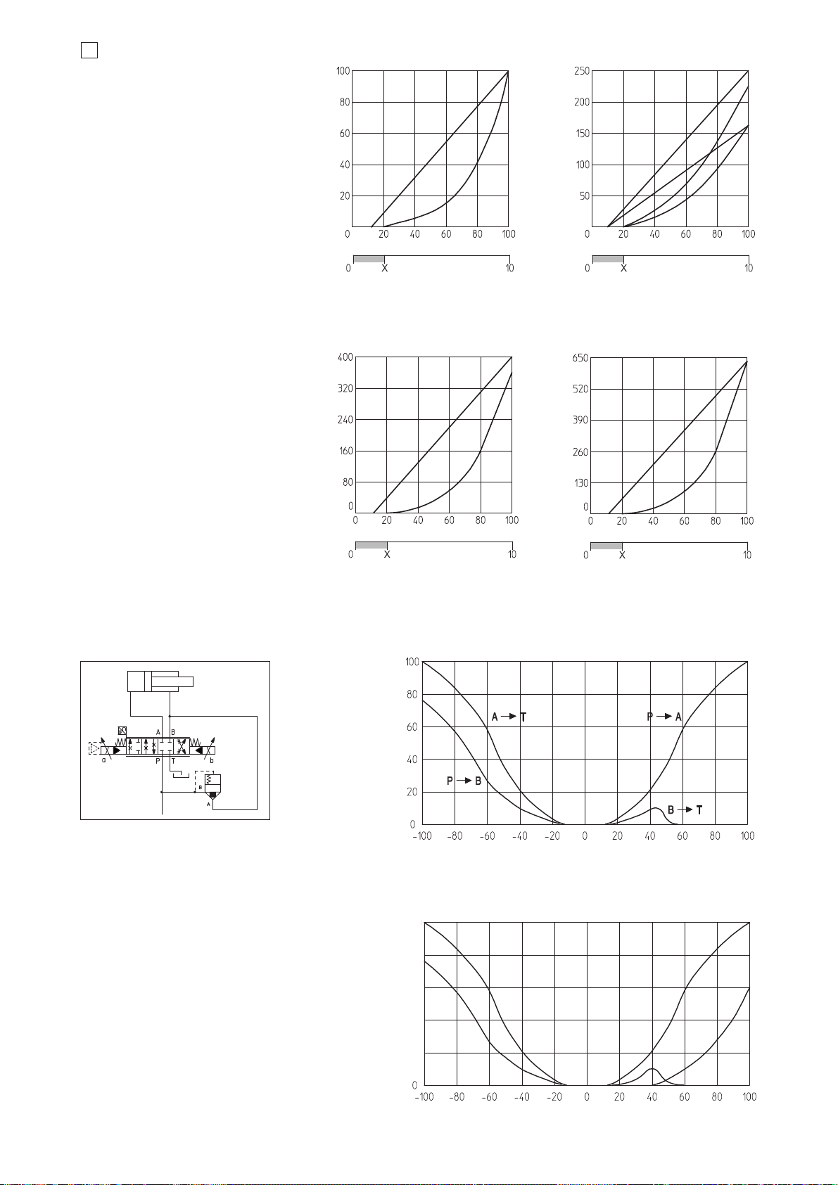
13
DIAGRAMS (based on mineral oil ISO VG 46 at 50 °C)
13.1 Regulation diagrams
DPZO-1:
1 = 1L5, 1DL5, 3L5, 3DL5
2 = 1S5, 1D5, 3S5, 3D5
DPZO-2:
3 = 1L5, 1DL5, 3L5, 3DL5
4 = 1S5, 1D5, 3S5, 3D5
5 = 1L3, 3L3
6 = 1S3, 1D3, 3S3, 3D3
DPZO-4:
7 = 1L5, 1DL5, 3L5, 3DL5
8 = 1S5, 1D5, 3S5, 3D5
DPZO-6:
9 = 1L5, 3L5
10 = 1S5, 1D5, 3S5, 3D5
F172
Stroke [% of max]
7
8
Max flow [l/min] at Δp = 10 bar
Stroke [% of max] Stroke [% of max]
2
1
3
4
6
Notes:
Hydraulic configuration vs. reference signal
for double solenoid valves (standard and option /B):
Reference signal 0 ÷+10 V
P 촞 A / B 촞 T
12÷20 mA
Reference signal 0 ÷-10 V
P 촞 B / A 촞 T
4÷12 mA
Hydraulic configuration vs. reference signal
for single solenoid valves:
Reference signal 0 ÷+10 V P 촞 A / B 촞 T (standard)
12÷20 mA P 촞 B / A 촞 T (option /B)
Reference signal [V]
X = Threshold for bias activation depending to the valve type and amplifier type
Reference signal [V]
X =
Threshold for bias activation depending to the valve type and amplifier type
Reference signal [V]
5
11 = differential - regenerative spool D9
Flow rate [% of max]
Stroke [% of max]
11
Application example
12 = linear - internal regenerative spool L9
50
100
150
200
250
Max flow [l/min] at Δp = 10 bar
Stroke [% of max]
12
L9 spool type with a fourth position specific to
regenerative circuit internal to the valve.
1 = P - B
2 = A - T
3 = P - A
4 = B - T
5 = P - B (regenerative)
3
2
1
5
4
D9 spool type with a fourth position specific to regenerative circuit,
performed by means of an additional external check valve.
}
}
}
Max flow [l/min] at Δp = 10 bar
Stroke [% of max]
10
9
Reference signal [V]
Page 81
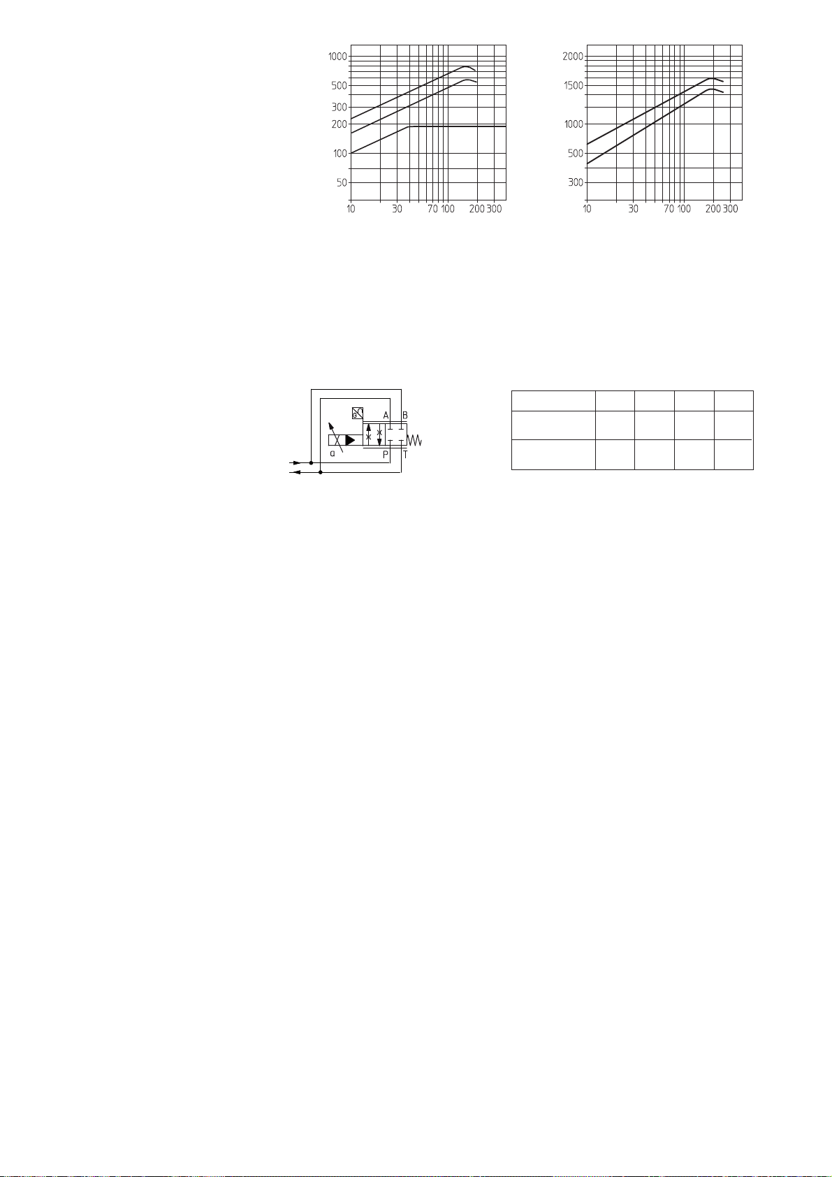
13.2 Operating diagrams
Flow /Δp diagram
stated at 100% of spool stroke
DPZO-1:
1 = spools L5, S5, D5, DL5, D9
DPZO-2:
2 = spool L3, S3, D3
3 = spools L5, S5, D5, DL5, D9, L9
DPZO-4:
4 = spools L5, S5, D5, DL5, D9
DPZO-6:
5 = spools L5, S5, D5
Flow rate [l/min]
Valve pressure drop Δp [bar]
2
3
4
5
1
Flow rate [l/min]
Valve pressure drop Δp [bar]
Max flow [l/min]
13.3 Dynamic response
The response times in section
쪩
have to be considered as average values.
For the valves with digital electronics the dynamics performances can be optimized by setting the internal software parameters.
160 430
151-L5 251-L5
DPZO-*-
Δp [bar]
30 30
830
451-L5
30
1100
651-L5
30
13.4 Operation as throttle valve
Single solenoid valves (*51) can be
used as simple throttle valves:
Pmax = 250 bar
Page 82
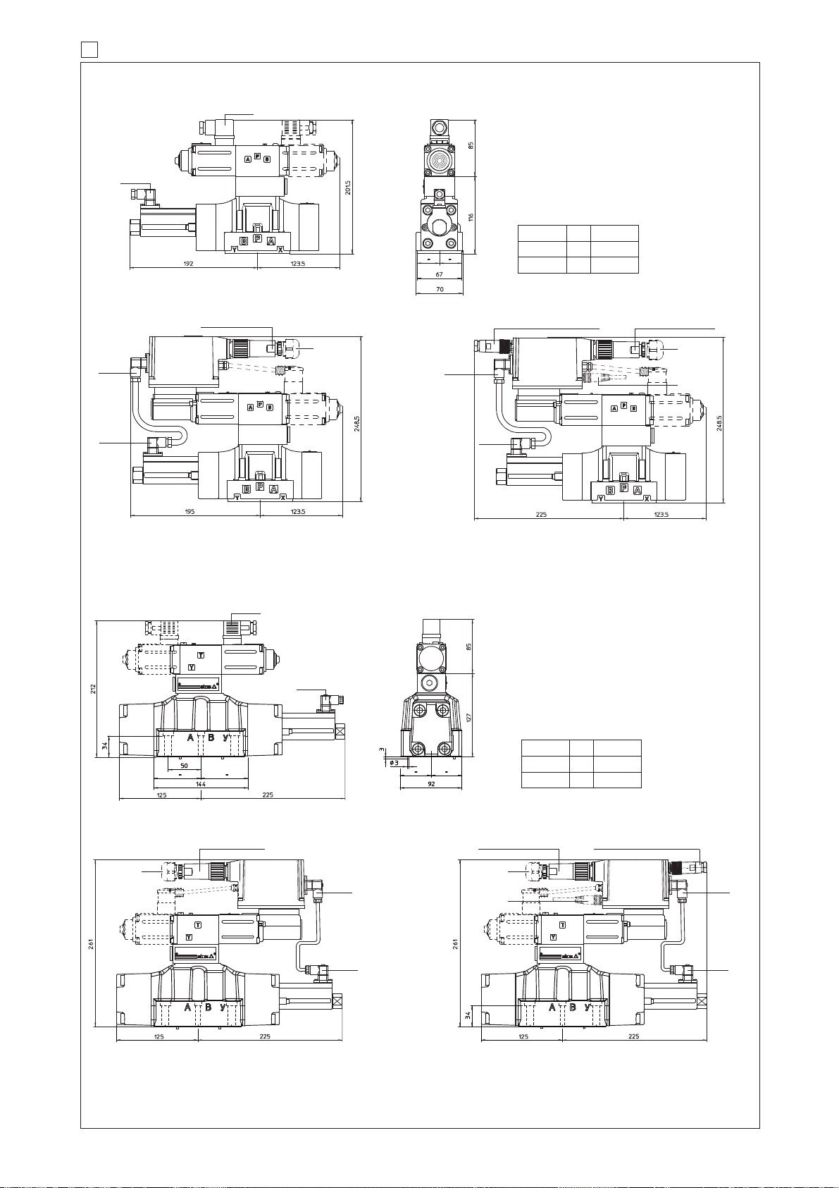
345
ZH-5P/BP (for -BP)
ZH-5P (for -PS and -BC)
14 INSTALLATION DIMENSIONS FOR DPZO-1 AND DPZO-2 [mm]
DPZO-T(*)-1
ISO 4401: 2005
Mounting surface: 4401-05-05-0-05 (see table P005)
Fastening bolts:
4 socket head screws M6x40 class 12.9
Tightening torque = 15 Nm
Seals: 5 OR 2050; 2 OR 108
Diameter of ports A, B, P, T: Ø = 11 mm;
Diameter of ports X, Y: Ø = 5 mm;
DPZO-T(*)-2
ISO 4401: 2005
Mounting surface: 4401-07-07-0-05 (see table P005)
Fastening bolts:
4 socket head screws M10x50 class 12.9
Tightening torque = 70 Nm
2 socket head screws M6x45 class 12.9
Tightening torque = 15 Nm
Seals: 4 OR 130; 3 OR 109/70
Diameter of ports A, B, P, T: Ø = 20 mm;
Diameter of ports X, Y: Ø = 7 mm;
Mass [kg]
DPZO-*-15*
8,5
T TE, TES
9,4
8,9
9,8
DPZO-*-17*
Mass [kg]
DPZO-*-25*
13,5
T TE, TES
14,4
13,9
14,8
DPZO-*-27*
DPZO-T-1
DPZO-TE-1
DPZO-TES-*-1
DPZO-T-2
DPZO-TE-2 DPZO-TES-*-2
F172
쩸
쩸
쩹
쩹
쩸
쩸
345
345
345
345
666
ZH-7P or ZM-7P
ZH-7P or ZM-7P
345
345
345
345
345
666
ZH-7P or ZM-7P
ZH-7P or ZM-7P
ZH-5P/BP (for -BP)
ZH-5P (for -PS and -BC)
쩸
쩹
NOTE:
For option /B the proportional solenoid, the position transducer and the electronics (in case of execution -TE and -TES) are at side of port A of the main stage.
(dotted line = double solenoid version)
(dotted line = double solenoid version)
Dotted line =12 pin connector ZH-12P for options /SF, /SL, /SP, /Z
= M8 connector ZH-4P-M8/5 moulded on cable 5 mt lenght for pressure or force transducer (options /SL, /SP)
M8 connector ZH-4P-M8/2-2 moulded with 2 cables, 2 mt lenght for 2 pressure
transducers (options /SF)
Page 83
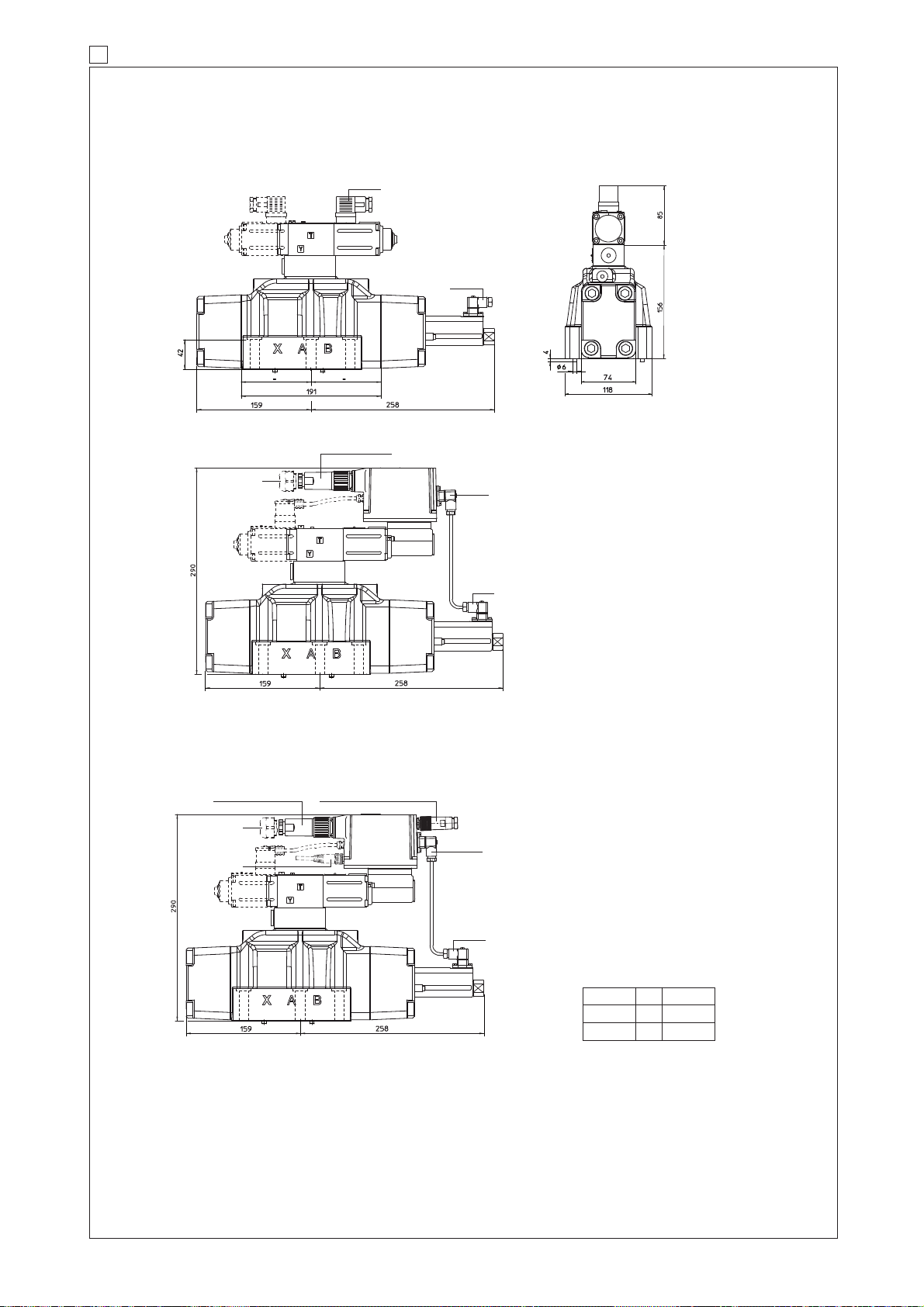
15 INSTALLATION DIMENSIONS FOR DPZO-4 [mm]
DPZO-T(*)-4
Mass [kg]
DPZO-*-45*
17,6
T TE, TES
18,51818,9
DPZO-*-47*
DPZO-T-4
DPZO-TE-4
쩸
345
345
345
666
NOTE:
For option /B the proportional solenoid, the position transducer and the electronics (in case of execution -TE and -TES) are at side of port A of the main
stage.
ZH-7P or ZM-7P
(dotted line = double solenoid version)
DPZO-TES-*-4
쩸
345
345
쩸
쩹
ZH-7P or ZM-7P
ZH-5P/BP (for -BP)
ZH-5P (for -PS and -BC)
쩹
Dotted line =12 pin connector ZH-12P for options /SF, /SL, /SP, /Z
= M8 connector ZH-4P-M8/5 moulded on cable 5 mt lenght for pressure or force transducer (options /SL, /SP)
M8 connector ZH-4P-M8/2-2 moulded with 2 cables, 2 mt lenght for 2 pressure transducers (options /SF)
ISO 4401: 2005
Mounting surface: 4401-08-08-0-05 (see table P005)
Fastening bolts:
6 socket head screws M12x60 class 12.9
Tightening torque = 125 Nm
Seals: 4 OR 4112; 2 OR 3056
Diameter of ports A, B, P, T: Ø = 24 mm;
Diameter of ports X, Y: Ø = 7 mm;
F172
Page 84
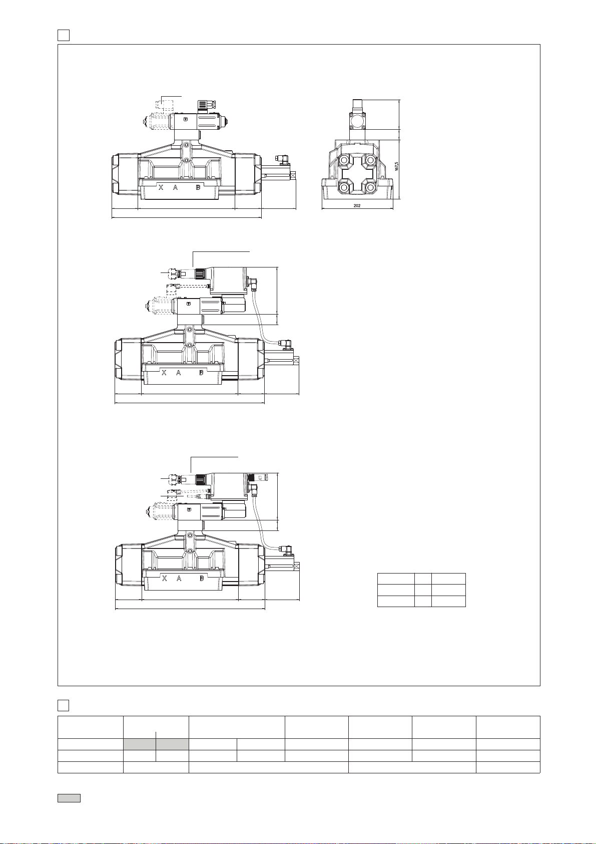
345
666
MODEL CODES OF POWER SUPPLY AND COMMUNICATION CONNECTORS (to be ordered separately)
VALVE VERSION
CONNECTOR CODE
ZH-7P ZM-7P ZH-12P ZH-5P ZH-5P/BP
PROTECTION DEGREE
IP65
Power supply Transducer
IP65 IP67 IP67 IP67 IP67 IP67
-T
-TE, -TES
-TE/Z
-TES /Z, /SF, /SL, /SP
serial (-PS)
or CANopen (-BC)
PROFIBUS DP (-BP)
ZH-4P-M8/*
(1)
IP67
TES /SF, /SL, /SP
(transducer)
17
connectors supplied with the valve
DATA SHEET
K500 G200, G210, K500 G210, K500
03/15
DPZO-T(*)-6
DPZO-T-6
DPZO-TE-6
NOTE:
For option /B the proportional solenoid, the position transducer and the electronics (in case of execution -TE and -TES) are at side of port A of the main stage.
(dotted line = double solenoid version)
DPZO-TES-6
쩸
쩹
Dotted line =12 pin connector ZH-12P for options /SF, /SL, /SP, /Z
= M8 connector ZH-4P-M8/5 moulded on cable 5 mt lenght for pressure or force transducer (options /SL, /SP)
M8 connector ZH-4P-M8/2-2 moulded with 2 cables, 2 mt lenght for 2 pressure transducers (options /SF)
(1) M8 connector ZH-4P-M8/5 moulded on cable 5 mt lenght for pressure or force transducer (options /SL, /SP)
M8 connector ZH-4P-M8/2-2 moulded with 2 cables, 2 mt lenght for 2 pressure transducers (options /SF)
G212, K500
16 INSTALLATION DIMENSIONS FOR DPZO-6 [mm]
Mass [kg]
DPZO-*-65*
41,7
T TE, TES
42,5
42,3
43,1
DPZO-*-67*
13030
100
80 80
435
275
13030
100
80 80
435
275
30
85
100
80 80
435
275
666
ZH-7P or ZM-7P
ZH-7P or ZM-7P
쩸
쩹
쩸
-TES EXECUTION
ISO 4401: 2005
Mounting surface:
4401-10-09-0-05
Fastening bolts:
6 socket head screws M20x90 class 12.9
Tightening torque = 600 Nm
Diameter of ports A, B, P, T: Ø = 34 mm;
Diameter of ports X, Y: Ø = 7 mm;
Seals: 4 OR 144, 3 OR 3056
Page 85
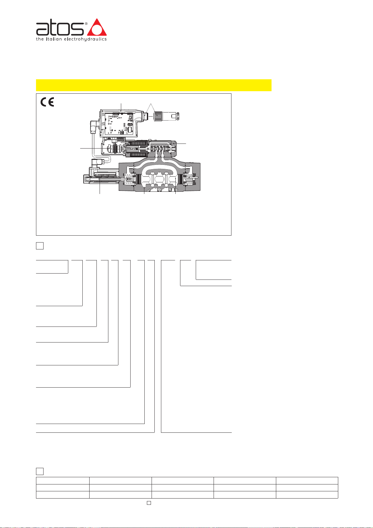
www.atos.com
Proportional directional valves type DPZO-LES
DPZO-LE-271
DPZO
L = with two integral
LE = as L plus integral
LES = with digital
1 = 10; 4 = 25; 6 = 32;
2 = 16 4M = 27;
쪩
0 = zero overlapping (only for spool type L, DL and T) (1)
1 = P, A, B, T with positive overlapping (2)
3 =
(2)
쪩
LES PS
27 –1L5/ /***/ *–––
1
MODEL CODE
Hydraulic options, see section
쪪
B =
G =pressure reducing valve for piloting
E =external pilot (through port X)
D =internal drain
Electronic options for -LE execution
쪭
F = fault signal
I =current reference input and monitor
Q =enable signal
Z = enable, fault and monitor signal (12
Electronic options
for -LES execution
쪯
I =current reference input and monitor
Z = double power supply, enable, fault and
Special options for -LES execution
쪯
SF =
SL = additional closed loop force con-
SP = additional closed loop pressure
C =
PS = Serial
BC = CANopen
BP = PROFIBUS DP
쪨
6 = 2 external position, spring offset (only for spool
7 = 3 position, spring centered
A
B
2
ELECTRONIC DRIVERS
-L
-LE
-LES
L = linear;
S = progressive;
D =
DL =
Q =
(3)
T = non linear
V =
(3)
쪨
They are high performance valves particularly used in closed loop positioning
or speed controls with high dynamic
requirements.
Note: For power supply and communication connector see section 16
Notes:
(1)
(2) Overlapping = 20% of spool stroke for type S, D and Q; 10% of spool stroke for type L and DL
(3)
-LES / SF, SL, SP
PE = FPM
LE and LES executions included in this table are available only for running supplies or spare parts
For new applications it is suggested new LEB and LES executions, see table FS175
Page 86
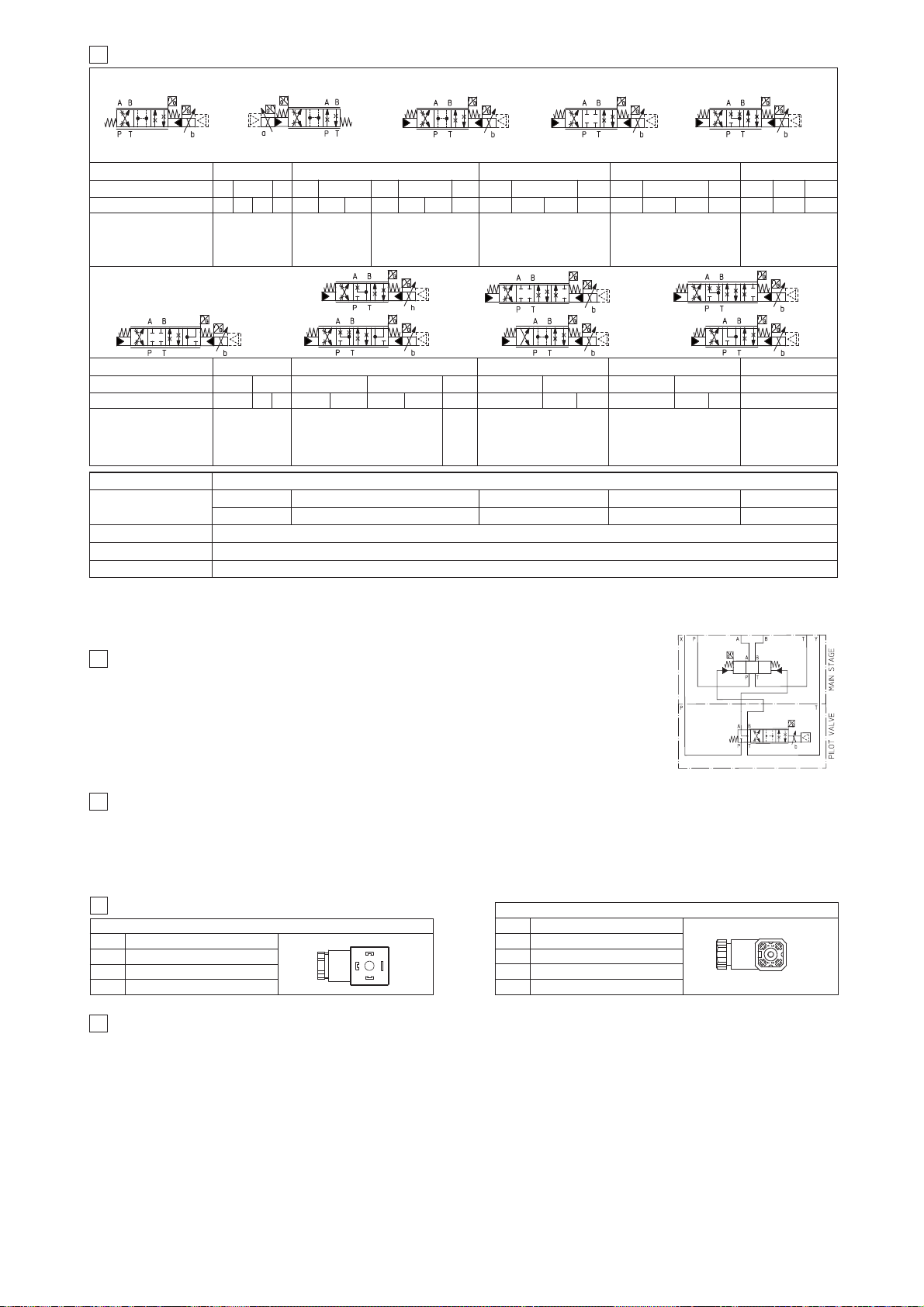
S5
L5 D5 DL5
1, 3
0, 1, 3
D3 D5
DL5
0, 1, 3
0, 1, 3
1, 3
L5 S5
0, 1, 3
1, 3
L3 S3
0, 1, 3
1, 3
L5 S5D5
DL5
0, 1, 3
4
HYDRAULIC OPTIONS
4.1 Option /B Solenoid, integral electronics and position transducer at side of port B of the main stage.
4.2 Option /G
4.3 Pilot and drain configuration -The pilot / drain configuration can be modified as shown in the table E080
1
2
3
4
POSITION TRANSDUCER CONNECTOR (pilot and main stage)
6
CONNECTIONS FOR -L EXECUTION
1
2
3
SOLENOID POWER SUPPLY CONNECTOR
Power supply
Reference input signal
Monitor output signal
7.1 Option /F It provides a Fault output signal in place of the Monitor output signal, to indicate fault conditions of the driver (cable interruption of spool
7.2 Option /I It provides the 4÷20 mA current reference and monitor signals instead of the standard ±10 V
7.3 Option /Q It provides the possibility to enable or disable the valve functioning without cutting the power supply (the valve functioning is disabled but
7.4 Option /Z
7.5 Possible combined options: /FI and /IZ
7 ANALOG INTEGRAL DRIVERS -LE - OPTIONS
3
HYDRAULIC CHARACTERISTICS OF STANDARD SPOOL (based on mineral oil ISO VG 46 at 50 °C) (3)
Standard spools - hydraulic symbols
Specific spools - hydraulic symbols
DPZO-L*-4
DPZO-L*-6
DPZO-L*-2
DPZO-L*-1
Notes:
쪨
5
GENERAL NOTES
0, 1, 3
1, 3
D9
Q5 V9
D9
L9 Q5 V9
0
T5
DPZO-L*-2DPZO-L*-1
1, 3
≤ 0,1%
3
3
Q5
V9
DPZO-L*-4M
3
S5
L5 D5
1, 3
0, 1, 3
1, 3
102
FUNCTIONAL SCHEME
S5L5 D5 DL5
1, 3
0, 1, 3
DPZO-L*-4M
0, 1, 3
1, 3
D9
Q5
V9
DPZO-L*-4
3
1, 3
D9
DPZO-L*-6
S5
1, 3
Page 87
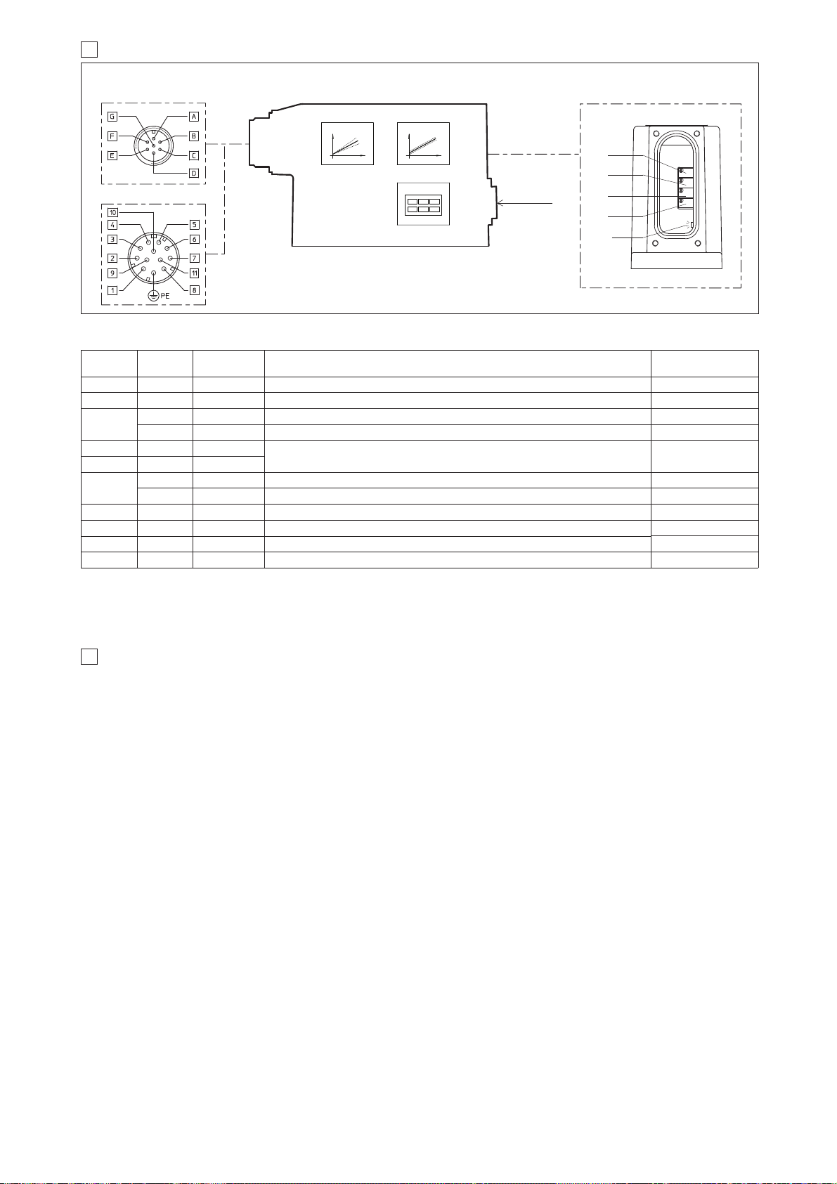
9 DIGITAL INTEGRAL DRIVERS -LES - OPTIONS
8 ANALOG INTEGRAL DRIVERS -LE - MAIN FUNCTIONS AND ELECTRONIC CONNECTIONS
12 PIN - OPTION /Z
REGULATIONS AND LED
7 PIN - STANDARD
MAIN CONNECTOR
Standard
7pin
/Z option
12pin
SIGNAL
TECHNICAL SPECIFICATIONS
NOTES
Notes:
B2
B1
S2
S1
LED:
쩨
쩨
쩨
쩨
LED
쩨
8.1 ELECTRONIC CONNECTIONS - 7 & 12 PIN MAIN CONNECTORS
OFF normal working; ON fault presence
B1:
B2:
S1:
S2:
Power supply
Reference input signal
Monitor output signal
9.1 Option /I
9.2 Option /Z
Logic power supply
Enable Input Signal
Fault Output Signal
9.3 Options /SP, /SF and /SL
9.4 Options /C
9.5 Possible combined options: /ISP, /ISF, /ISL, /CSP, /CSF, /CSL, /CISP, /CISF, /CISL and /IZ
SPOOL POSITION
SIGNAL
Page 88
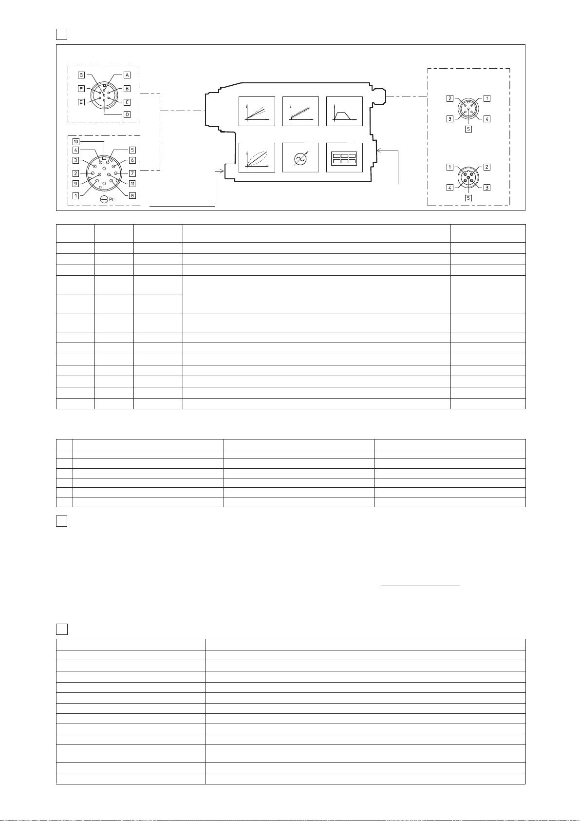
10.2 ELECTRONIC CONNECTIONS - 5 PIN COMMUNICATION CONNECTORS
10.1 ELECTRONIC CONNECTIONS - 7 & 12 PIN MAIN CONNECTORS
-PS Serial -BC CANopen -BP PROFIBUS DP
PIN SIGNAL TECHNICAL SPECIFICATION SIGNAL TECHNICAL SPECIFICATION SIGNAL TECHNICAL SPECIFICATION
Standard
7pin
/Z option
12pin
SIGNAL TECHNICAL SPECIFICATIONS NOTES
10 DIGITAL INTEGRAL DRIVERS -LES - MAIN FUNCTIONS AND ELECTRONIC CONNECTIONS
COMMUNICATION
CONNECTOR
12 PIN - OPTION /Z, /SP, /SF and /SL
7 PIN - STANDARD
5 PIN reverse key
PROFIBUS DP (-BP)
5 PIN
Serial (-PS) or
CANopen (-BC)
CONNECTOR FOR
REMOTE PRESSURE
(FORCE) TRANDUCER
11
SOFTWARE TOOLS
MAIN CONNECTOR
Note: A minimum time of 300 to 500 ms have be considered between the driver energizing with the 24 V
쪧
12
MAIN CHARACTERISTICS OF PROPORTIONAL DIRECTIONAL VALVES
SPOOL POSITION
SIGNAL
Programming software, must be ordered separately:
E-SW-* (mandatory - first supply) = Dvd including E-SW-* software installer and operator manuals; it allows the registration to Atos digital service
E-SW-*-N (optional - next supplies) = as above but not allowing the registration to Atos digital service
Page 89
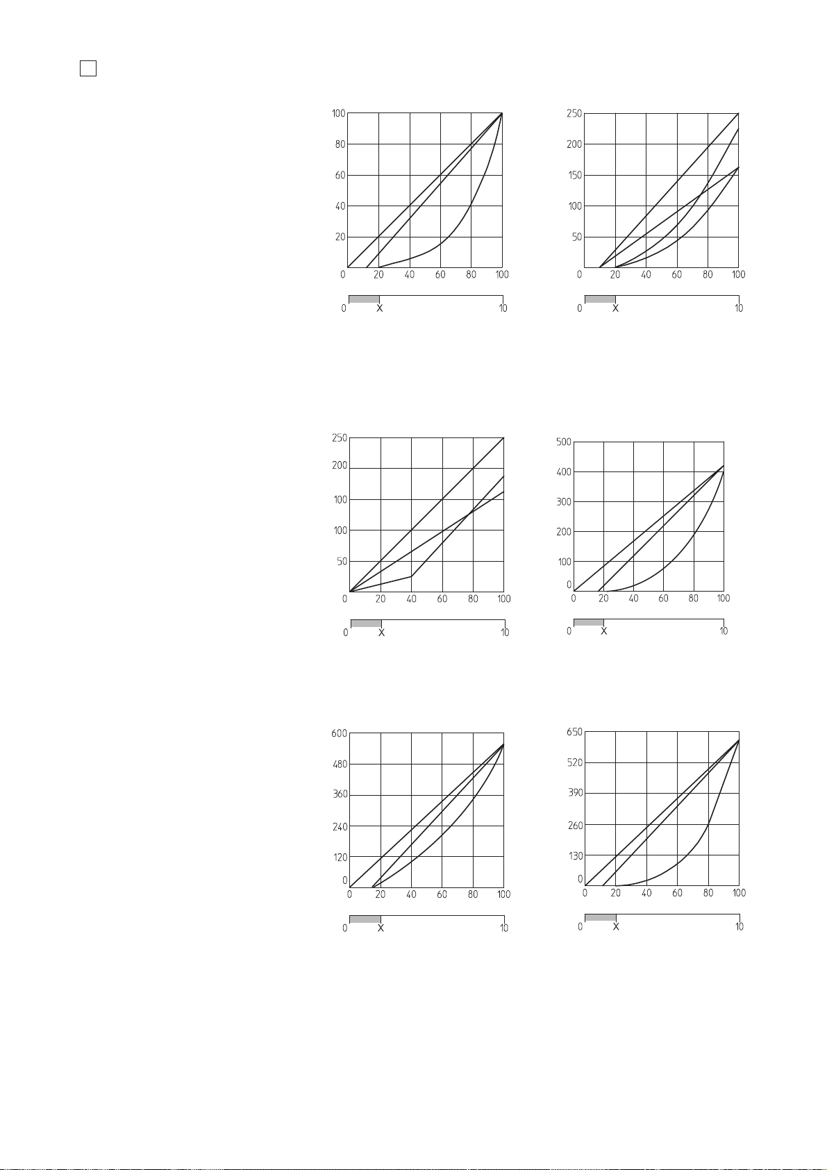
13
DIAGRAMS (based on mineral oil ISO VG 46 at 50 °C)
13.1 Regulation diagrams
1 = 0L5, 0DL5
2 = 1L5, 3L5, 1DL5, 3DL5
3 = 1S5, 1D5, 3S5, 3D5
4 = 1L5, 3L5, 1DL5, 3DL5
5 = 1S5, 1D5, 3S5, 3D5
6 = 1L3, 3L3
7 = 1S3, 1D3, 3S3, 3D3
8 = 0L5, 0DL5
9 = 0L3
10 = 0T5 not linear spool (only for DPZO-2)
11 = 0L5, 0DL5
12 = 1L5, 1DL5, 3L5, 3DL5
13 = 1S5, 1D5, 3S5, 3D5
14 = 0L5, 0DL5
15 = 1L5, 1DL5, 3L5, 3DL5
16 = 1S5, 1D5, 3S5, 3D5
17 = 0L5, 0DL5
18 = 1L5, 3L5
19 = 1S5, 1D5, 3S5, 3D5
8
9
3
2
1
4
5
7
X = Threshold for bias activation depending to the valve type and amplifier type
6
Note:
19
18
17
10
11
12
13
14
15
16
Page 90
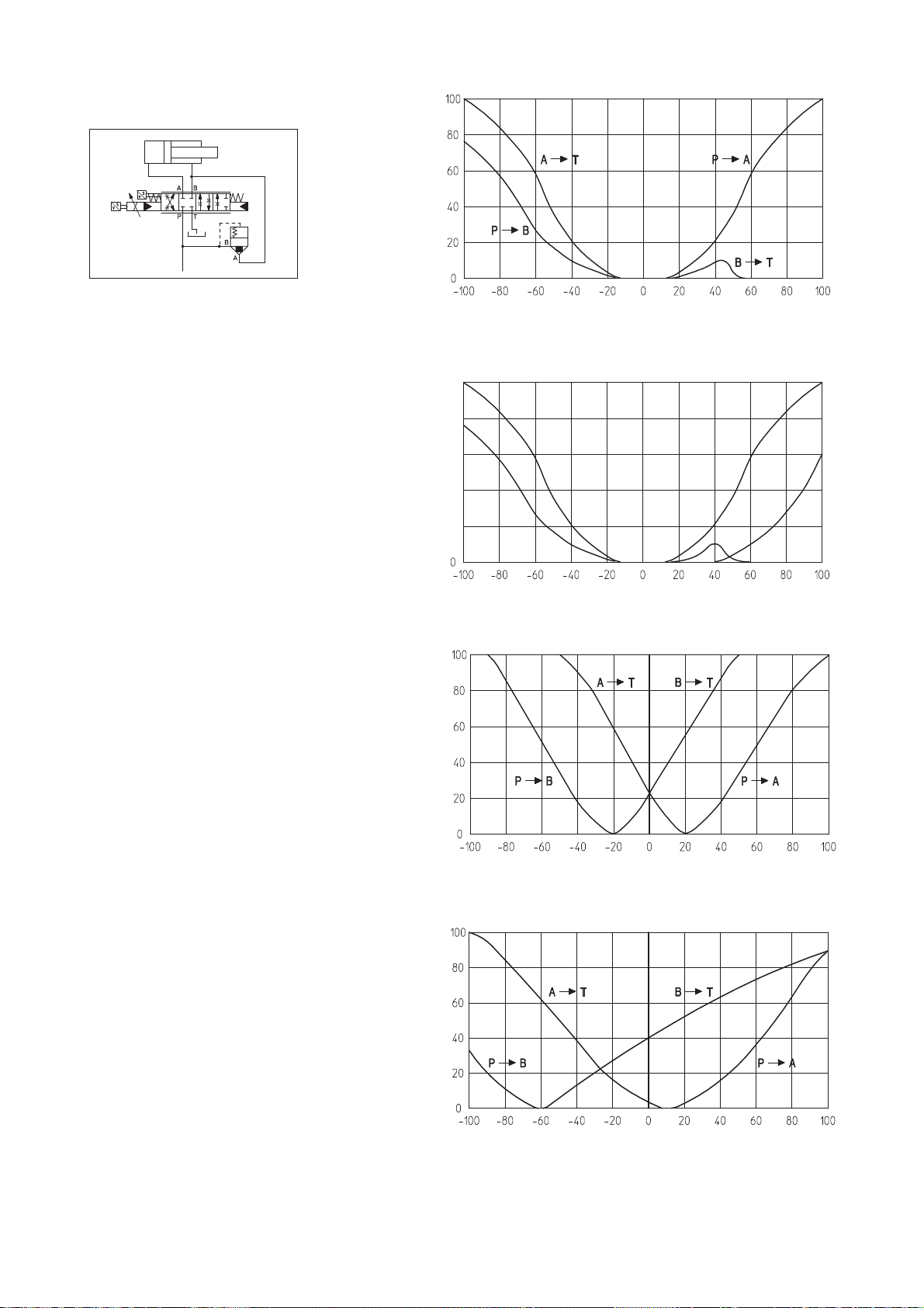
17
17 = differential - regenerative spool D9
18 =
18
1 = P - B
2 = A - T
3 = P - A
4 = B - T
5 = P - B (regenerative)
3
2
1
5
4
20 = differential - progressive spool V9
20
19
19 = linear spool Q5 (not available for size 32)
Page 91
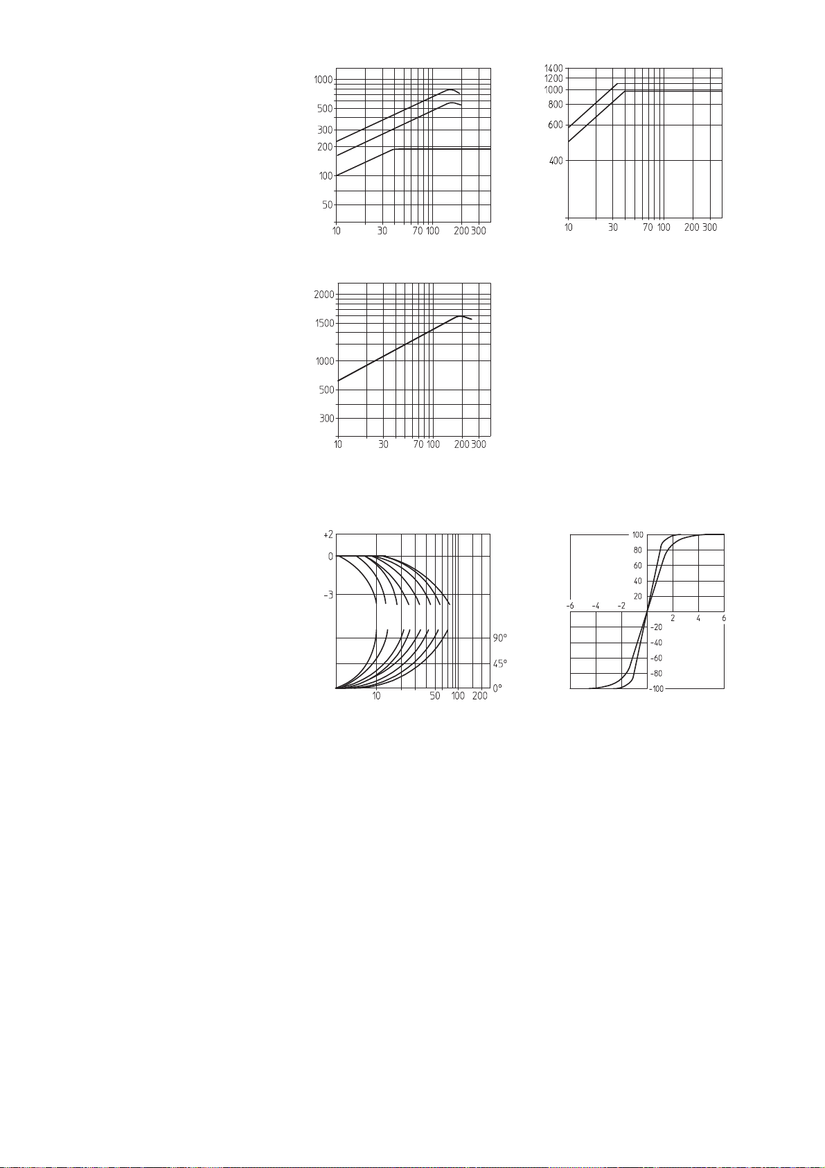
13.2 Operating diagrams
Flow /Δp diagram
1 = spools L5, S5, D5, DL5, D9, V9
2 = spool L3, S3, D3, T5
3 = spools L5, S5, D5, DL5, D9, L9, V9
4 = spools L5, S5, D5, DL5, D9, V9
5 = spools L5, S5, D5, DL5, D9, V9
6 = all spools
13.3 Bode diagrams
1 = 160 and 170 ± 100%
2 = 160 and 170 ± 5%
3 = 260 and 270 ± 100%
4 = 260 and 270 ± 5%
5 = 460 and 470 ± 100%
6 = 460 and 470 ± 5%
7 = 660 and 670 ± 100%
8 = 660 and 670 ± 5%
13.4 Pressure gain
9 = DPZO-L(*)-1 *60 and *70
10 = DPZO-L(*)-260, -270
587 3 1642
587 31642
13.5 Dynamic response
쪨
ΔP A촞B [%P]
910
2
3
6
1
4
5
Page 92
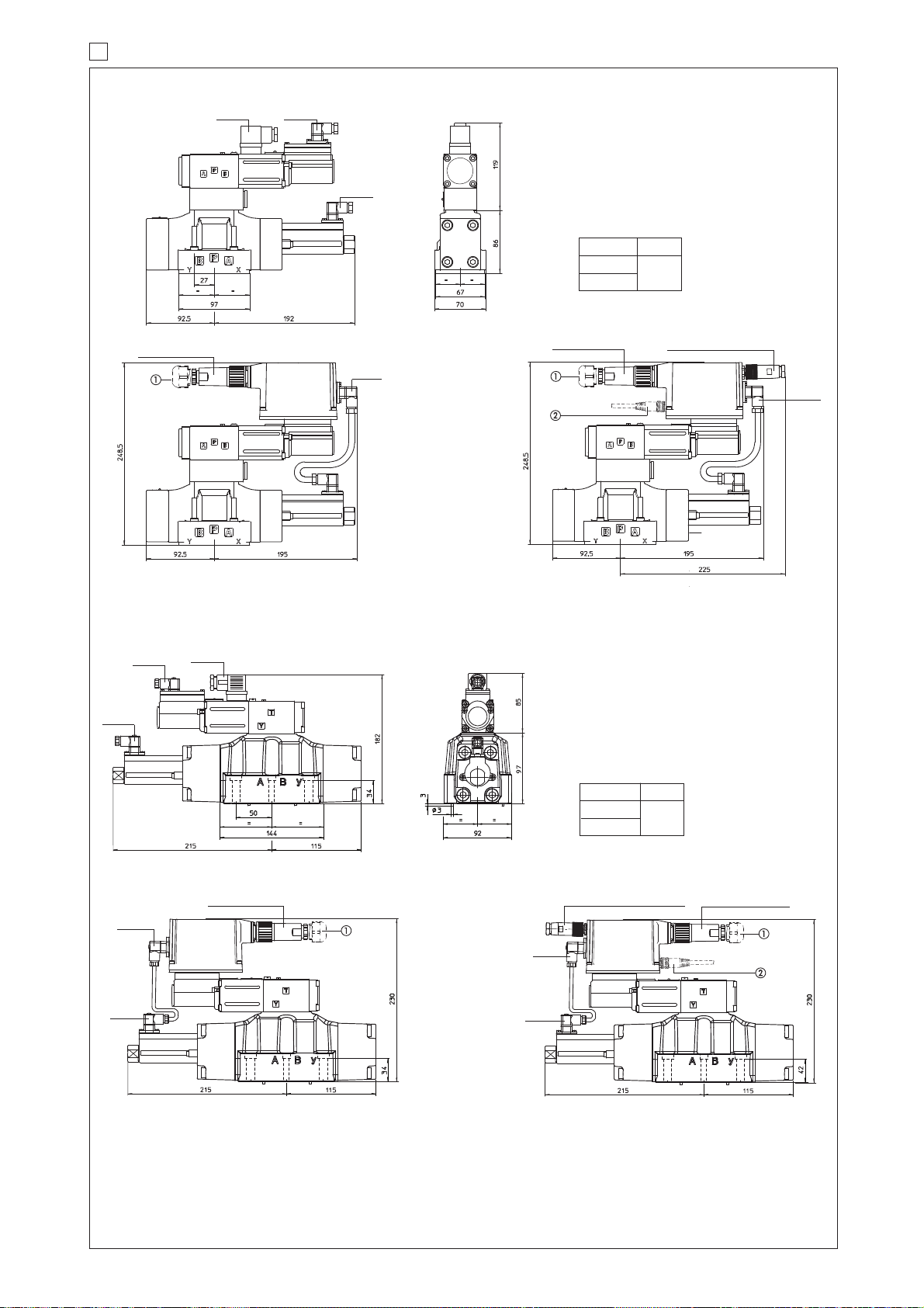
14 INSTALLATION DIMENSIONS FOR DPZO-1 AND DPZO-2 [mm]
DPZO-L(*)-2
DPZO-L(*)-1
NOTE: The overall height is increased by 30 mm for /G option (0,9 kg).
ISO 4401: 2005
Mounting surface: 4401-07-07-0-05
ISO 4401: 2005
Mounting surface: 4401-05-05-0-05
Mass [kg]
Mass [kg]
DPZO-LES-*-1
DPZO-L-2
DPZO-LE-2
DPZO-LES-*-2
쩸
쩹
DPZO-LE-1
ZH-7P or ZM-7P
666 345
345
345
ZH-5P/BP (for -BP)
ZH-7P or ZM-7P
ZH-5P (for -PS and -BC)
345
345
345
345
345
666
ZH-7P or ZM-7P
ZH-5P/BP (for -BP)
ZH-5P (for -PS and -BC)
345
345
ZH-7P or ZM-7P
Page 93
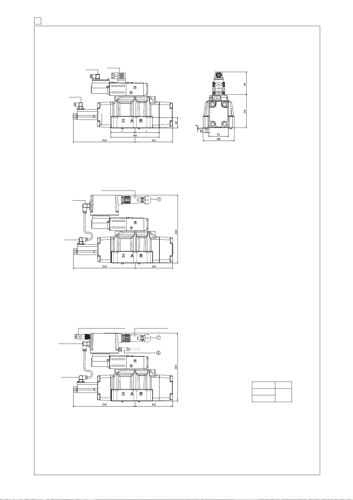
666
345
ZH-7P or ZM-7P
ZH-7P or ZM-7P
ZH-5P/BP (for -BP)
ZH-5P (for -PS and -BC)
345
345
345
345
345
15 INSTALLATION DIMENSIONS FOR DPZO-4 and DPZO-4M [mm]
DPZO-L(*)-4
DPZO-L(*)-4M
NOTE: The overall height is increased by 40 mm for /G option (0,9 kg).
쩸
쩹
DPZO-L-4
DPZO-L-4M
DPZO-LE-4
DPZO-LE-4M
DPZO-LES- *-4
DPZO-LES- *-4M
ISO 4401: 2005
Mounting surface: 4401-08-08-0-05
DPZO-4
Mass [kg]
DPZO-4M
Page 94
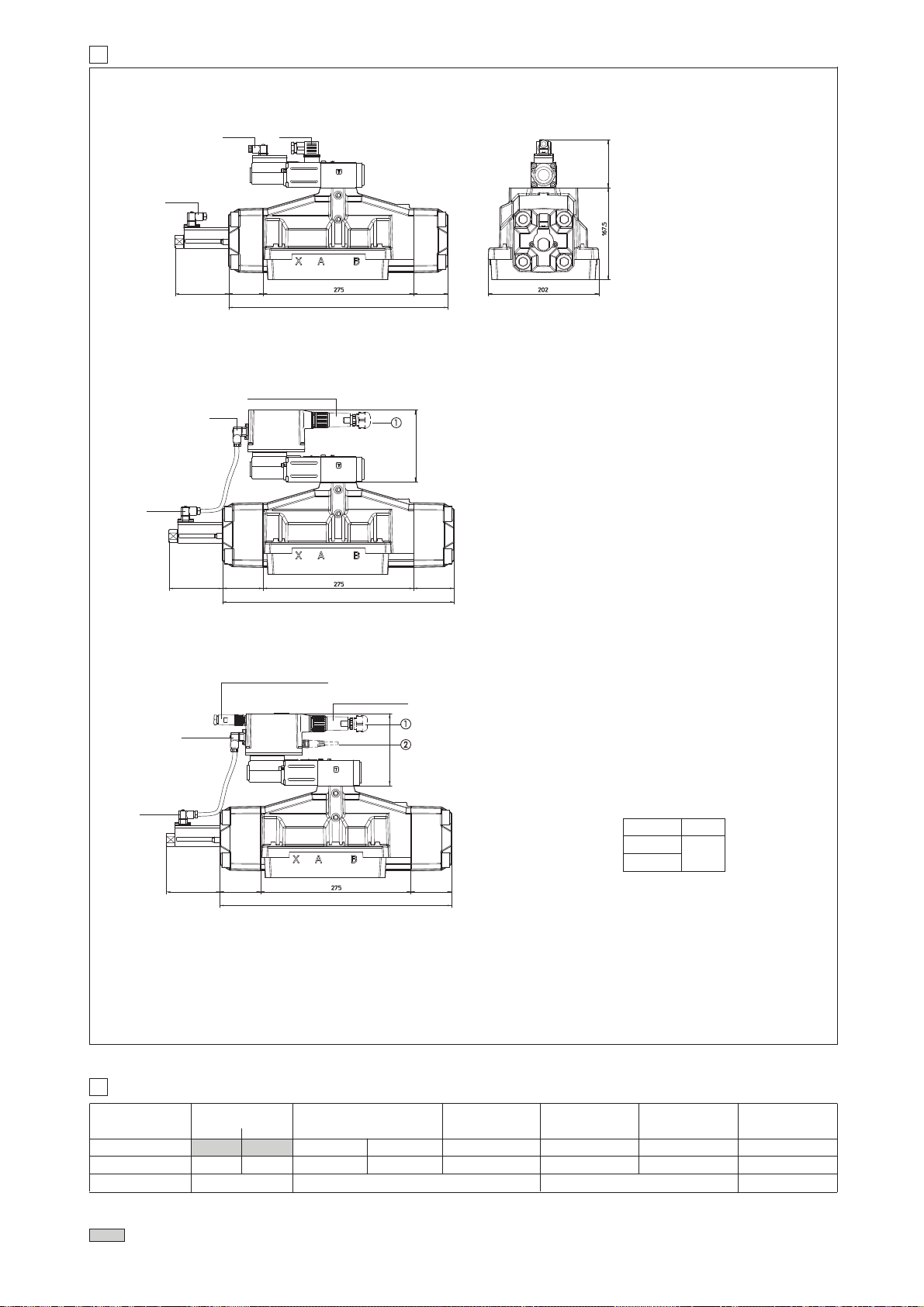
100
0606
395
130
85
99
0606
395
99
60
60
395
133,5
666
345
ZH-7P or ZM-7P
ZH-7P or ZM-7P
ZH-5P/BP (for -BP)
ZH-5P (for -PS and -BC)
345
345
345
345
345
16 INSTALLATION DIMENSIONS FOR DPZO-6 [mm]
DPZO-L(*)-6
NOTE: The overall height is increased by 40 mm for /G option (0,9 kg).
Mass [kg]
DPZO-L-6
DPZO-LE-6
DPZO-LES- *-6
MODEL CODES OF POWER SUPPLY AND COMMUNICATION CONNECTORS (to be ordered separately)
VALVE VERSION
CONNECTOR CODE
PROTECTION DEGREE
Power supply Transducer
-L
-LE, -LES
-LE/Z
-LES /Z, /SF, /SL, /SP
serial (-PS)
or CANopen (-BC)
PROFIBUS DP (-BP)
TES /SF, /SL, /SP
(transducer)
17
DATA SHEET
쩸
쩹
ISO 4401: 2005
Mounting surface:
4401-10-09-0-05
Page 95
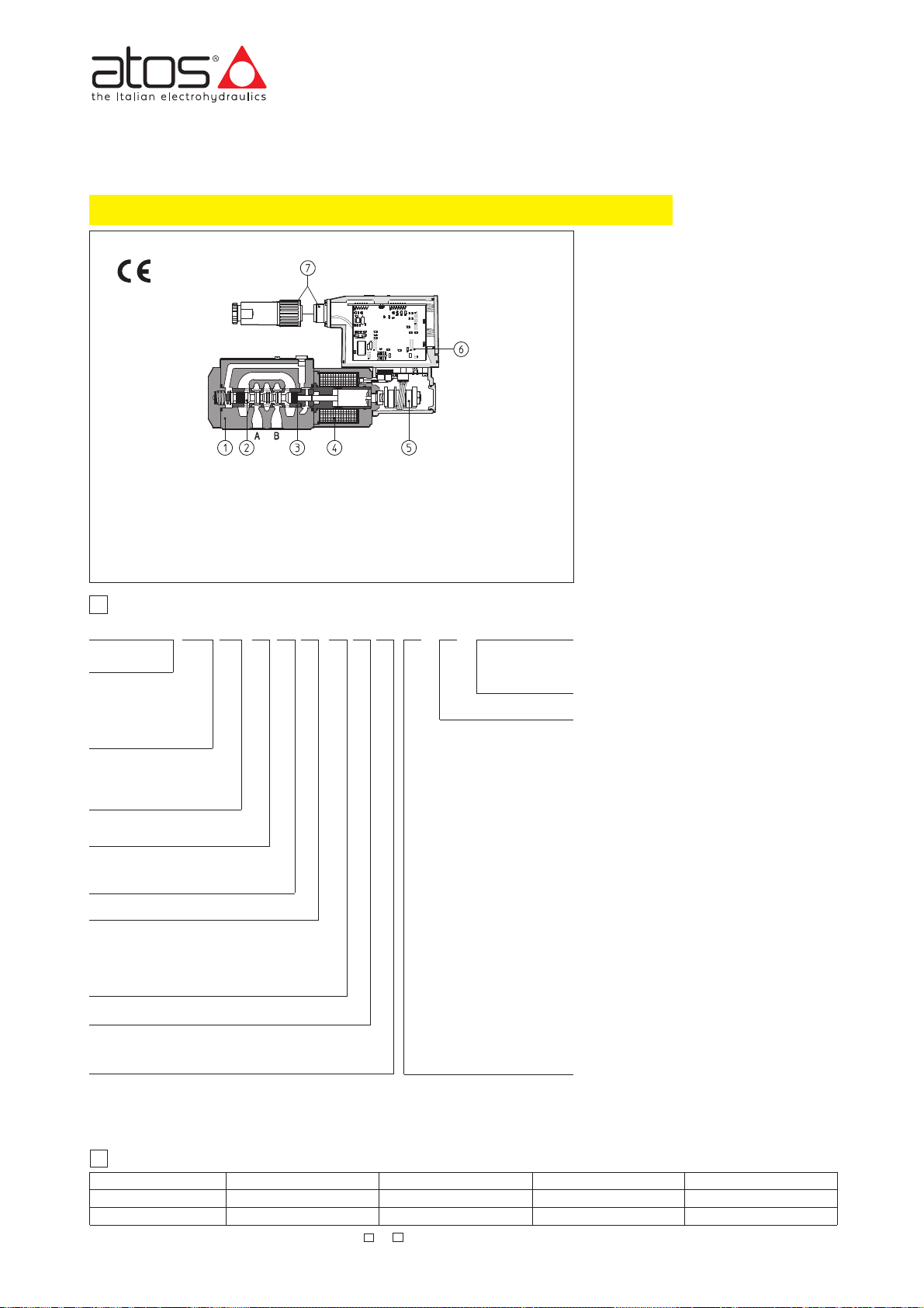
www.atos.com
Servoproportional valves type DLHZO-TE and DLKZOR-TE
sleeve execution, direct operated, with position transducer, ISO 4401 size 06 and 10
Table F180-17/E
1 MODEL CODE
DLKZOR-TE-160
DLHZO
DLHZO = size 06
DLKZOR = size 10
T = with position transducer
TE = as T with integral analog
electronics
TES = with digital electronics
Valve configuration, see section
쪨
4 = spring offset with fail safe
6 = spring offset
0 = zero overlapping
0, 1, 3, 5, 7 = spool size, see section
쪩
Notes:
(1) Spool type D, DT and T are available only for valve configuration with fail safe position DLHZO-*-040 and DLKZOR-*-140
Fail safe configuration (de-energized solenoid):
1 = A, B, P, T with positive overlapping (20% of spool stroke)
3 = P positive overlapping (20% of spool stroke); A, B, T negative
Series number
TES PS 40L-0*/73 **/ *---
Valve size , see section
쪨
0 = ISO 4401 size 06 1 = ISO 4401 size 10
Communication interfaces (only for TES)
PS = Serial
BC = CANopen
BP = PROFIBUS DP
DLHZO and DLKZOR are high
performance servoproportional valves,
direct operated, with sleeve execution and
LVDT position transducer, which provide
both directional and non compensated
flow control according to the electronic
reference signal.
They operate in association with electronic
drivers, see section
쪨
, which supply the
proportional valves with proper current to
align valve regulation to the reference
signal supplied to the electronic driver.
They are available in different executions:
• -T, with integral position transducer 햶;
• -TE, -TES as -T plus analog (TE) or
digital (TES) integral electronics 햷.
The 4-way spool 햳 is sliding into a
precision - machined and hardened sleeve
햴 for maximum overlapping accuracy.
The sleeve 햴 is mechanically forced into a
5-chambers body 햲.
The spool is directly
operated by a proportional solenoids 햵 and
it is controlled in closed loop position by
means of the LVDT position transducer 햶
.
The integral electronics 햷 ensures factory
presetting, fine functionality plus valve-tovalve interchangeability and simplified
wiring and installation.
The electronic main connector 햹 is fully
interchangable for -TE and -TES
executions.
Standard 7 pin main connector is used for
power supply, analog input reference and
monitor signals.
12 pin connector is used for options /Z
and /S*.
The special /S* options add a closed loop
control of pressure (/SP) or force (/SF and
/SL) to the basic closed loop spool position one.
Following communication interfaces 쩾are
available for the digital -TES execution:
• -PS, Serial communication interface for
configuration, monitoring and firmware
updating through Atos PC software
• -BC, CANopen interface
• -BP, PROFIBUS DP interface
The valves with -BC and -BP interfaces
can be integrated into a fieldbus
communication network and thus digitally
operated by the machine control unit.
The coils are fully plastic encapsulated
(insulation class H) and the valves have
antivibration, antishock and weather-proof
features.
Mounting surface: ISO 4401 sizes 06 and 10.
Max flow respectively up to 40 l/min and
100 l/min with valve differential pressure
Δp = 70 bar, see table
쪩
.
Max pressure = 350 bar
Hydraulic options, see section쪪:
B = solenoid, integral electronics and
position transducer at side of port A
Y = external drain
Electronics options, for -TE execution
see section
쪭
:
F =fault signal
I = current reference input and monitor
(4÷20 mA)
Q =enable signal
Z =enable, fault and monitor signals (12
pin connector)
Electronics options, for -TES execution
see section
쪯
:
I =current reference input and monitor
(4÷20mA)
Z =
double power supply, enable fault and
monitor signals (12 pin connector)
Special options for -TES execution
see section 쪯:
SF =
additional closed loop force control,
with two remote pressure transducers
SL = additional closed loop force control
with one remote load cell
SP = additional closed loop pressure
control with one remote pressure
transducer
C = current feedback interface for transdu-
cer(s) only for options /SF, /SL, /SP
Spool type (regulating characteristics)
L = linear;
D = differential-linear (as L, but with P-A = Q, P-B = Q/2)
(2)
DT = as D, but with non linear regulation (1)
T = not linear regulation
(1)
V = progressive
/
2 ELECTRONIC DRIVERS
Valve model
Data sheet
Drivers model E-ME-T
G140
-T
E-RI-TE
G200
-TE
E-RI-TES
G210
-TES
Note: For power supply and communication connector see section 15 and 17
Position transducer
Integral electronics
Main connector
Valve body
Spool
Sleeve
Proportional solenoid
F180
E-RI-TES / SF, SL, SP
G212
-TES / SF, SL, SP
Seals material:
omit for NBR (mineral
oil & water glycol)
PE = FPM
TE and TES executions included in this table are available only for running supplies or spare parts
For new applications it is suggested new TEB and TES executions, see table FS180
Page 96
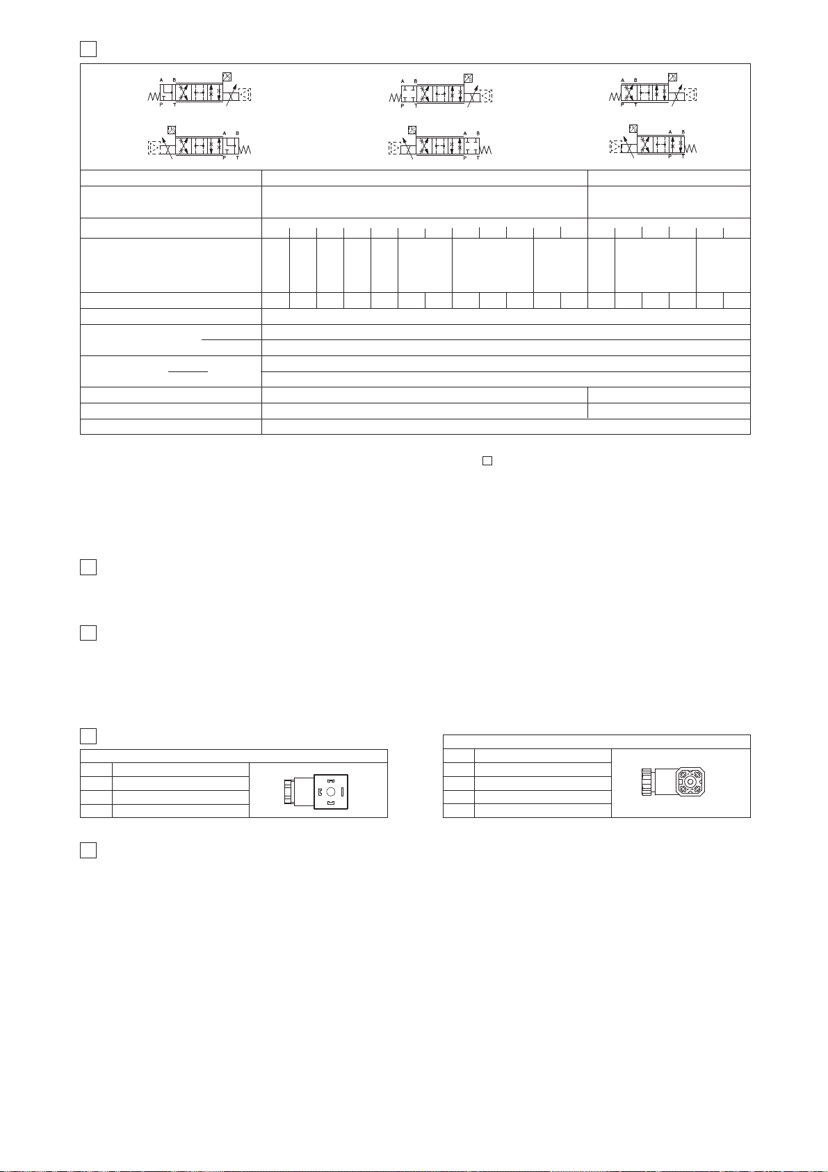
2
Valve model
Pressure limits [bar]
DLHZO-T*
ports P, A, B = 350;
T = 210 (250 with external drain /Y)
3
HYDRAULIC CHARACTERISTICS (based on mineral oil ISO VG 46 at 50 °C)
DLKZOR-T*
ports P, A, B =
315;
T = 210
(250 with external drain /Y)
Spool
Leakage [cm
3
/min] at P = 100 bar (2)
Fail safe connections
Fail safe 1
Fail safe 3
DLHZO
DLKZOR
Fail safe 3
Response time
(5) [ms]
Hysteresis [%]
Thermal drift
≤ 10
≤ 0,1%
P → AP → BA → TB → T
50 70 70 50
50 70 - -
- - 15÷30 10÷20
- - 40÷60 25÷40
≤ 15
≤ 0,1%
Hydraulic
symbols
*60-L*1
*60-V*1
b
b
*60-L*1/B
*60-V*1/B
a
a
a
b
zero point displacement < 1% at ΔT = 40°C
Signal description
OUTPUT SIGNAL
SUPPLY -15 V
DC
SUPPLY +15 VDC
GND
PIN
1
2
3
4
POSITION TRANSDUCER CONNECTOR
6
CONNECTIONS FOR -T EXECUTION
DLHZO and DLKZOR servoproportional valves are CE marked according to the applicable Directives (e.g. Immunity/Emission EMC Directive and Low Voltage Directive).
Installation, wirings and start-up procedures must be performed according to the general prescriptions shown in table F003 and in the installation notes
supplied with relevant components.
The electrical signals of the valve (e.g. monitor signals) must not be directly used to activate safety functions, like to switch-ON/OFF the machine’s safety
components, as prescribed by the European standards (Safety requirements of fluid technology systems and components-hydraulics, EN-982).
Signal description
SUPPLY
SUPPLY
GND
PIN
1
2
3
SOLENOID POWER SUPPLY CONNECTOR
1
2
3
1
2
3
4
5
GENERAL NOTES
Standard driver execution provides on the 7 pin main connector:
Power supply
- 24VDC must be appropriately stabilized or rectified and filtered; a 2,5 A safety fuse is required in series to the driver power supply
Apply at least a 10000 μF/40 V capacitance to single phase rectifiers or a 4700 μF/40 V capacitance to three phase rectifiers
Reference input signal
- analog differential input with ±10 VDC nominal range (pin D, E), proportional to desired valve spool position
Monitor output signal
- analog output signal proportional to the actual valve’s spool position with ±10 VDC nominal range
Following options are available to adapt standard execution to special application requirements:
7.1 Option /F
It provides a Fault output signal in place of the Monitor output signal, to indicate fault conditions of the driver (cable interruption of spool transducers or
reference signal - for /I option): Fault presence corresponds to 0 V
DC, normal working corresponds to 24 VDC.
7.2 Option /I
It provides the 4÷20 mA current reference and monitor signals instead of the standard ±10 VDC
It is normally used in case of long distance between the machine control unit and the valve or where the reference signal can be affected by electrical
noise; the valve functioning is disabled in case of reference signal cable breakage.
7.3 Option /Q
It provides the possibility to enable or disable the valve functioning without cutting the power supply (the valve functioning is disabled but the driver current output stage is still active). To enable the driver supply a 24VDC on the enable input signal.
7.4 Option /Z
This option includes /F and /Q features, plus the Monitor output signal.
When the driver is disabled (
0 VDC
on Enable signal) Fault output is forced to 0
VDC
.
7.5 Possible combined options: /FI and /IZ
7 ANALOG INTEGRAL DRIVERS -TE - OPTIONS
4
HYDRAULIC OPTIONS
4.1 Option /B Solenoid, integral electronics and position transducer at side of port A.
4.2 Option /Y External drain is mandatary if the pressure in port T exceeds 160 bar.
L0
Max flow
(1) [l/min]
at Δp = 30 bar
at Δp = 70 bar
max permissible flow
2,5
4
8
L1 V1 L3 V3 L5 T5 L7 T7 V7 D7 DT7 L3 L7 T7 V7 D7 DT7
4,5
7
14
5
8
16
9
14
30
13
20
40
18
28
50
26
40
70
26÷13
40÷20
70÷40
40
60
90
60
100
160
60÷33
100÷50
160÷80
Notes:
앬
Above performance data refer to valves coupled with Atos electronic drivers,
see sections .
앬
The flow regulated by the directional proportional valves is not pressure compensated, thus it is affected by the load variations.To keep costant the regulated
flow under different load conditions, modular pressure compensators are available (see tab. D150).
(1) For different
Δ
p, the max flow is in accordance to the diagrams in section 13.2
(2) Referred to spool in neutral position and 50°C oil temperature.
(3) Referred to spool in fail safe position and 50°C oil temperature.
(4) Referred to spool in fail safe position at
Δ
p = 35 bar per edge and
50°C oil temperature.
(5) 0-100% step signal
<200
<300 <500
<200 <900 <200
<1000 <1500 <400
<100 <100 <150 <200 <200<700
<1200
<400 <400
*40-L*3/B
*40-D*3/B
*40-DT*3/B
*40-T*3/B
*40-V*3/B
*40-L*1/B
*40-D*1/B
*40-DT*1/B
*40-T*1/B
*40-V*1/B
*40-L*3
*40-D*3
*40-DT*3
*40-T*3
*40-V*3
*40-D*1
*40-DT*1
*40-T*1
*40-V*1
Leakage [cm
3
/min]
at P = 100 bar
(3)
Flow [l/min] (4)
Page 97
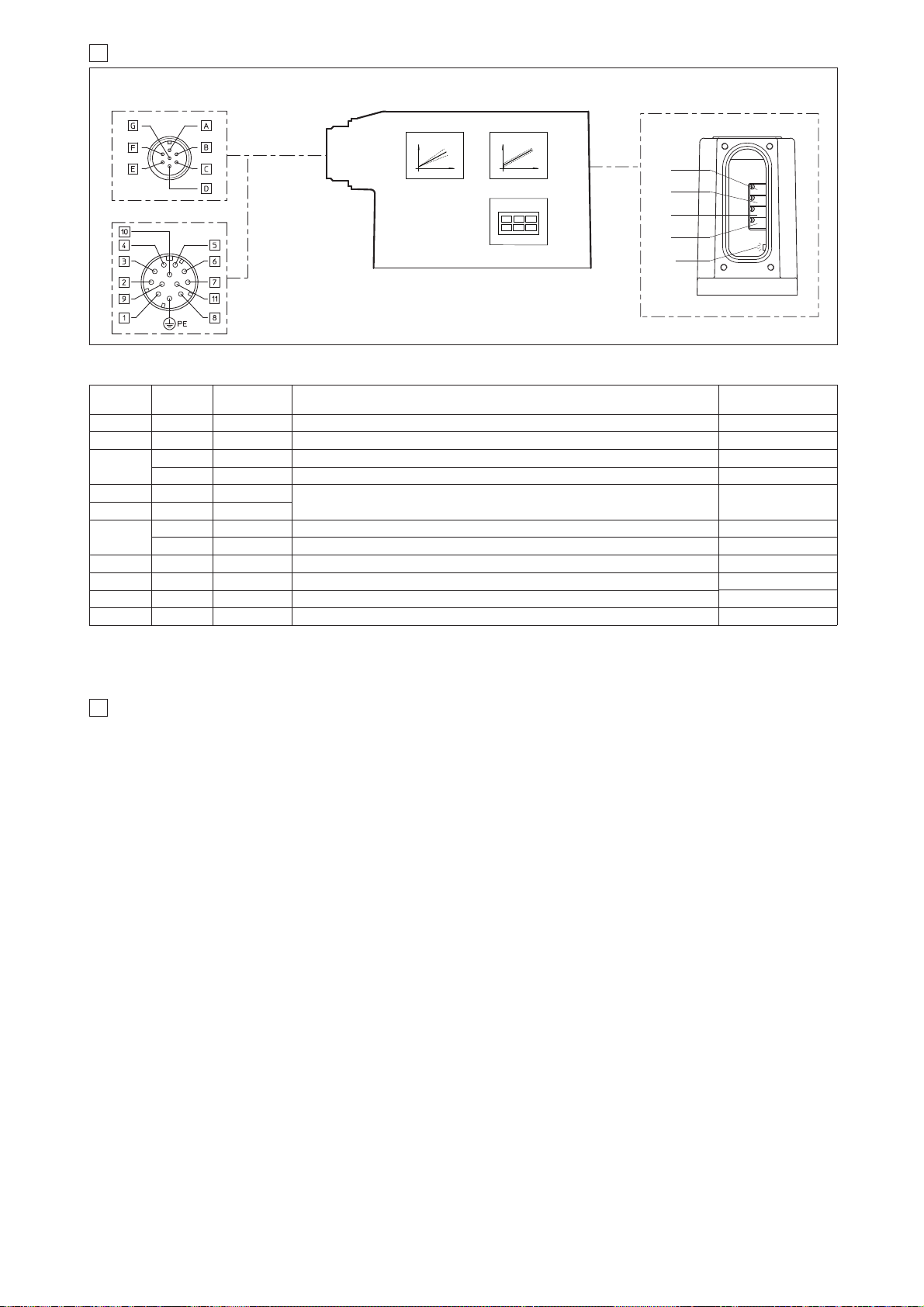
9 DIGITAL INTEGRAL DRIVERS -TES - OPTIONS
8 ANALOG INTEGRAL DRIVERS -TE - MAIN FUNCTIONS AND ELECTRONIC CONNECTIONS
12 PIN - OPTION /Z
REGULATIONS AND LED
7 PIN - STANDARD
MAIN CONNECTOR
BIAS
SCALE
DIAGNOSTIC
B2
B1
S2
S1
bias adjust
LED:
쩨
쩨
쩨
쩨
LED
쩨
(driver view)
(driver view)
8.1 ELECTRONIC CONNECTIONS - 7 & 12 PIN MAIN CONNECTORS
not working
positive scale adjust
negative scale adjust
OFF normal working; ON fault presence
B1:
B2:
S1:
S2:
Standard driver execution provides on the 7 pin main connector:
Power supply
- 24VDC must be appropriately stabilized or rectified and filtered; a 2,5 A safety fuse is required in series to each driver power supply
Apply at least a 10000 μF/40 V capacitance to single phase rectifiers or a 4700 μF/40 V capacitance to three phase rectifiers
Reference input signal
- analog differential input with ±10VDC nominal range (pin D,E), proportional to desired valve spool position
Monitor output signal
- analog output signal proportional to the actual valve’s spool position with ±10VDC nominal range
Following options are available to adapt standard execution to special application requirements:
9.1 Option /I
It provides 4÷20 mA current reference and monitor signals instead of the standard ±10 V.
It is normally used in case of long distance between the machine control unit and the valve or where the reference signal can be affected by electrical
noise; the valve functioning is disabled in case of reference signal cable breakage.
9.2 Option /Z
It provides, on the 12 pin main connector, the following additional features:
Logic power supply
Separated power supply for the solenoid (pin 1, 2) and for the digital electronic circuits (pin 9, 10).
Cutting solenoid power supply allows to interrupt the valve functioning but keeping energized the digital electronics thus avoiding fault conditions of the
machine fieldbus controller. This condition allows to realize safety systems in compliance with European Norms EN13849-1 (ex EN954-1).
Enable Input Signal
To enable the driver, supply 24V
DC on pin 3 referred to pin 2: when the Enable signal is set to zero the valve functioning is disabled (zero current to the
solenoid) but the driver current output stage is still active.
Fault Output Signal
Fault output signal indicates fault conditions of the driver (solenoid short circuits/not connected, reference signal cable broken for 4÷20mA input, etc.).
Fault presence corresponds to 0
VDC
, normal working corresponds to 24
VDC (pin 11 referred to pin 2)
: Fault status is not affected by the Enable input signal
9.3 Options /SP, /SF and /SL
These options add the closed loop control of pressure (/SP) or force (/SF and /SL) to the basic functions of proportional directional valves: a dedicated
software alternates pressure (force) and valve’s spool position controls depending on the actual hydraulic system conditions.
A dedicated connector is available for the additional transducers that are required to be interfaced to the valve’s driver (1 pressure transducer for /SP,
2 pressure transducers for /SF or 1 load cell for /SL).
Main 12 pin connector is the same as /Z option plus two analog signals specific for the pressure (force) control: one for reference (pin 7) and one for
monitor (pin 8).
For futher details please refer to the driver technical table G212.
9.4 Options /C
Options /CSP, /CSF and /CSL are available to connect pressure (force) transducers with 4 ÷ 20mA current output signal.
9.5 Possible combined options: /ISP, /ISF, /ISL, /CSP, /CSF, /CSL, /CISP, /CISF, /CISL and /IZ
(remove the rear cover)
Standard
7pin
/Z option
12pin
SIGNAL
TECHNICAL SPECIFICATIONS
NOTES
A 1 V+ Power supply 24 VDC for solenoid power stage and driver logic
Input - power supply
Gnd - power supply
B 2 V0 Power supply 0 VDC for solenoid power stage and driver logic
C
(1)
7 AGND Ground - signal zero for MONITOR signal (for standard and /Z options) Gnd - analog signal
3 ENABLE Enable (24 VDC) or disable (0 VDC) the driver (for /Q and /Z options) Input - on/off signal
D 4 INPUT+
Reference analog differential input: ±10 VDC maximum range (4 ÷ 20 mA for /I option)
Input - analog signal
E 5 INPUT -
F
(2)
6 MONITOR Monitor analog output: ±10 VDC maximum range (4 ÷ 20 mA for /I option) Output - analog signal
11 FAULT Fault (0V) or normal working (24V) (for F and /Z options) Output - on/off signal
- 8 R_ENABLE Repeat Enable - output repetition of Enable input Output - on/off signal
- 9 NC do not connect
Output - on/off signal
Output - on/off signal
- 10 NC do not connect
G PE EARTH
Internally connected to the driver housing
Notes (1) with /Q option ENABLE signal replaces AGND on pin C; MONITOR signal is reffered to pin B
(2) with /F option FAULT signal replaces MONITOR on pin F.
A minimum time of 50ms to 100ms have be considered between the driver energizing with the 24 V
DC power supply and when the valve is ready
to operate. During this time the current to the valve coils is switched to zero.
F180
Page 98
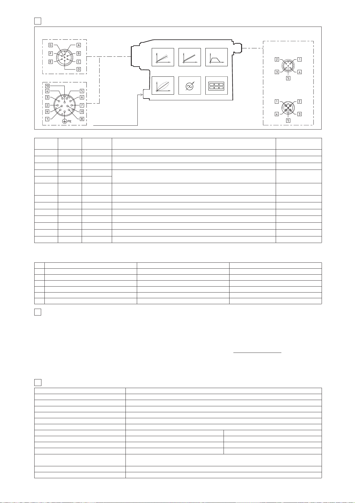
10.2 ELECTRONIC CONNECTIONS - 5 PIN COMMUNICATION CONNECTORS
10.1 ELECTRONIC CONNECTIONS - 7 & 12 PIN MAIN CONNECTORS
-PS Serial -BC CANopen -BP PROFIBUS DP
PIN SIGNAL TECHNICAL SPECIFICATION SIGNAL TECHNICAL SPECIFICATION SIGNAL TECHNICAL SPECIFICATION
1 NC do not connect CAN_SHLD Shield +5V for termination
2 NC do not connect NC do not connect LINE-A Bus line (high)
3 RS_GND Signal zero data line CAN_GND Signal zero data line DGND data line and termination Signal zero
4 RS_RX Valves receiving data line CAN_H Bus line (high) LINE-B Bus line (low)
5 RS_TX Valves transmitting data line CAN_L Bus line (low) SHIELD
Standard
7pin
/Z option
12pin
SIGNAL TECHNICAL SPECIFICATIONS NOTES
A 1 V+
Power supply 24 VDC for solenoid power stage (and for driver logic on 7 pin connection)
Input - power supply
Gnd - power supply
B 2 V0 Power supply 0 VDC for solenoid power stage (and for driver logic on 7 pin connection)
- 3 ENABLE Enable (24 VDC) or disable (0 VDC) the driver Input - on/off signal
D 4 INPUT+
Reference analog input: ±10 VDC maximum range (4 ÷ 20 mA for /I option)
standard: differential input; /Z option: common mode INPUT+ referred to AGND
Input - analog signal
E - INPUT -
C 5 AGND
Ground - signal zero for MONITOR signal
signal zero for INPUT+ signal ( only for /Z option)
Gnd - analog signal
F 6 MONITOR Monitor analog output: ±10 VDC maximum range (4 ÷ 20 mA for /I option) Output - analog signal
- 7 NC do not connect ( pressure/force input for /SP, /SF and /SL options, see 9.3 )
- 8 NC do not connect ( pressure/force monitor for /SP, /SF and /SL options, see 9.3 )
- 9 VL+ Power supply 24 VDC for driver logic
Input - power supply
Gnd - power supply
- 10 VL0 Power supply 0 VDC for driver logic
- 11 FAULT Fault (0V) or normal working (24V) Output - on/off signal
G PE EARTH Internally connected to the driver housing
10 DIGITAL INTEGRAL DRIVERS -TES - MAIN FUNCTIONS AND ELECTRONIC CONNECTIONS
COMMUNICATION
CONNECTOR
12 PIN - OPTION /Z, /SP, /SF and /SL
7 PIN - STANDARD
5 PIN reverse key
PROFIBUS DP (-BP)
5 PIN
Serial (-PS) or
CANopen (-BC)
RAMPSBIASSCALE
LINEARIZATION
FIELDBUS
REFERENCE
ENHANCED
DIAGNOSTIC
REMOTE PRESSURE
(FORCE) TRANDUCER
(for /SP, /SF and /SL)
11
SOFTWARE TOOLS
MAIN CONNECTOR
Note: A minimum time of 300 to 500 ms have be considered between the driver energizing with the 24 VDC power supply and when the valve is ready
to operate. During this time the current to the valve coils is switched to zero.
(driver view)
(driver view)
(driver view)
The driver configuration and parameters can be easily set with the Atos E-SW programming software, available in three different versions according to the
driver’s communication execution: E-SW-PS (Serial), E-SW-BC (CANopen) and E-SW-BP (PROFIBUS DP).
For a more detailed description of software interface, PC requirements, adapters, cables and terminators, please refer to technical table G500.
Programming software, must be ordered separately:
E-SW-* (mandatory - first supply) = Dvd including E-SW-* software installer and operator manuals; it allows the registration to Atos digital service
E-SW-*-N (optional - next supplies) = as above but not allowing the registration to Atos digital service
On first supply of the E-SW-* software, it is required to apply for the registration in the Atos download area: www.download.atos.com.
Once the registration is completed, the password will be sent by email.
The software remains active for 10 days from the installation date and then it stops until the user inputs his password.
With the password you can also download, in your personal area, the latest releases of the Atos software, manuals, drivers and configuration files.
Assembly position Any position
Subplate surface finishing Roughness index Ra 0,4 - flatness ratio 0,01/100 (ISO 1101)
Ambient temperature -20°C ÷ +70°C for -T execution; -20°C ÷ +60°C for -TE and TES executions
Fluid Hydraulic oil as per DIN 51524 ... 535 for other fluids see section
쪧
Recommended viscosity 15 ÷100 mm2/s at 40°C (ISO VG 15÷100)
Fluid contamination class ISO 4406 class 20/18/15 NAS 1638 class 9, in line filters of 10 μm (β
10 _>75 recommended)
Fluid temperature -20°C +60°C (standard seals and water glycol) -20°C +80°C (/PE seals)
12 MAIN CHARACTERISTICS OF PROPORTIONAL DIRECTIONAL VALVES
Valve model DLHZO-T* DLKZOR-T*
Coil resistance R at 20°C 3 ÷ 3,3 Ω
3,8 ÷ 4,1
Ω
Max. solenoid current 2,6 A 3 A
Max. power 35 Watt 40 Watt
Insulation class H (180°) Due to the occuring surface temperatures of the solenoid coils, the European standards
ISO 13732-1 and EN982 must be taken into account
Protection degree (CEI EN-60529)
IP65 for -T execution; IP67 for -TE and -TES executions
Duty factor Continuous rating (ED=100%)
Page 99
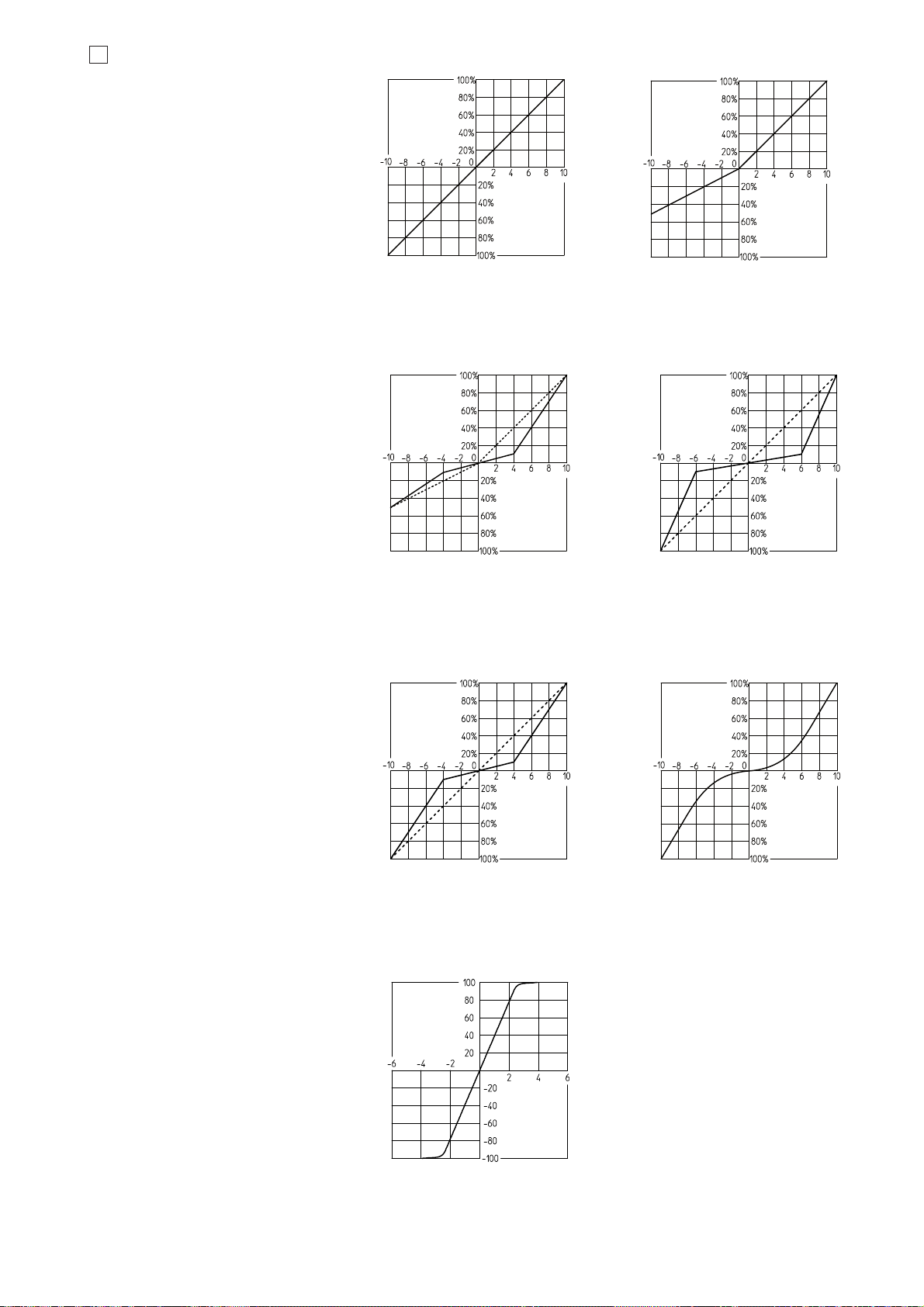
13
DIAGRAMS (based on mineral oil ISO VG 46 at 50 °C)
13.1 Regulation diagrams
1 = Linear spools L
2 = Differential - linear spool D7
F180
Nominal flow [%]
Nominal flow [%]
Reference signal [Volt] Reference signal [Volt]
12
3 = Differential non linear spool DT7
4 = Non linear spool T5 (only for DLHZO)
Nominal flow [%]
Reference signal [Volt]
3
Note:
Hydraulic configuration vs. reference signal:
Standard:
Reference signal 0 ÷+10 V P 촞 A / B 촞 T
12÷20 mA
Reference signal 0 ÷-10 V P 촞 B / A 촞 T
4÷12 mA
option /B:
Reference signal 0 ÷+10 V P 촞 B / A 촞 T
12÷20 mA
Reference signal 0 ÷-10 V P 촞 A / B 촞 T
4÷12 mA
Nominal flow [%]
Reference signal [Volt]
4
Nominal flow [%]
Reference signal [Volt]
5
Nominal flow [%]
Reference signal [Volt]
6
5 = Non linear spool T7
6 = Progressive spool V
7 = Pressure gain
Δp A촞B [%P]
Spool stroke [%]
7
T5 and T7 spool types are specific for fine
low flow control in the range from 0 to 60%
(T5) and 0 to 40% (T7) of max spool stroke.
The non linear characteristics of the spool is
compensated by the electronic driver, so the
final valve regulation is resulting linear
respect the reference signal (dotted line).
DT7 has the same characteristic of T7 but it
is specific for applications with cylinders with
area ratio 1:2
}
}
}
}
Page 100
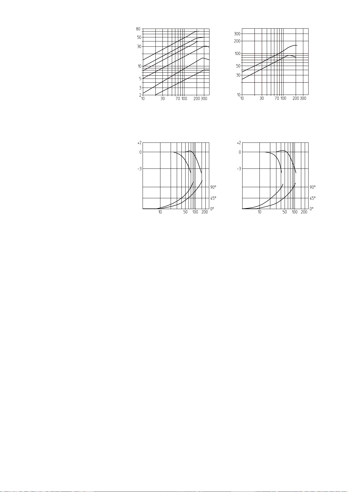
13.2 Flow /Δp diagrams
Stated at 100% of spool stroke
DLHZO:
1 = spool L7, T7, V7, D7, DT7
2 = spool L5, T5
3 = spool V3
4 = spool L3
5 = spool L1, V1
6 = spool L0
DLKZOR:
7 = spool L7, T7, V7, D7, DT7
8 = spool L3
13.3 Bode diagrams
Stated at nominal hydraulic conditions
DLHZO:
1 = ± 100% nominal stroke
2 = ± 5% nominal stroke
DLKZOR:
3 = ± 100% nominal stroke
4 = ± 5% nominal stroke
Flow rate [l/min]
Valve pressure drop Δp [bar]
Flow rate [l/min]
Valve pressure drop Δp [bar]
Amplitude ratio [dB]
Frequency [Hz]
Phase [degree]
Amplitude ratio [dB]
Frequency [Hz]
Phase [degree]
12
12
34
34
7
8
1
2
3
4
13.4 Dynamic response
The response times in section
쪩
have to be considered as average values.
For the valves with digital electronics the dynamics performances can be optimized by setting the internal software parameters.
5
6
 Loading...