


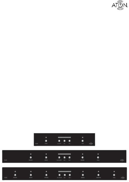
DLA2/DLA4/DLA6
Multi-Room Speaker
Level Audio Router
www.atonhome.com

DLA2/4/6 Speaker Level Audio Router
Safety Information
NOTE: This equipment has been tested and found to comply with the limits for a Class B digital device, pursuant to part 15 of the FCC Rules. These limits are designed to provide reasonable protection against harmful interference in a residential installation. This equipment generates, uses and can radiate radio frequency energy and, if not in-stalled and used in accordance with the instructions, may cause harmful interference to radio communications. However, there is no guarantee that interference will not occur in a particular installation.
If this equipment does cause harmful interference to radio or television reception, which can be determined by turning the equipment off and on, the user is encouraged to try to correct the interference by one or more of the following measures:
•Reorient or relocate the receiving antenna.
•Increase the separation between the equipment and receiver.
•Connect the equipment into an outlet on a circuit different from that to which the receiver is connected.
•Consult the dealer or an experienced radio/TV technician for help.
CAUTION: Changes or modi cations not expressly approved by Elan Home Systems could void the user’s authority to operate the equipment
DLA2/4/6 Power Source
The source of DLA2/4/6 power is the 12VDC wall transformer. A DC-IN jack connects the 12 VDC adapter with the DLA2/4/6 chassis to provide power for the unit. Protect the power supply cord from being walked on or pinched, particularly at plugs, outlets and the point where they exit from the apparatus.
Severe personal injury and equipment damage can result by not following proper procedures. Use only the 12VDC adapter designated for the DLA2/4/6.
Caring For the DLA2/4/6
Clean only with a dry soft cloth.
It is important to properly care for your DLA2/4/6 Speaker Selector. Follow these guidelines to ensure your device is preserved and protected.
•Do not expose the DLA2/4/6 to rain, liquids or moisture for an extended period of time.
•Do not expose the DLA2/4/6 to temperature extremes.
•Do not place any objects on top of the DLA2/4/6 to prevent chassis damage.
Operating Temperatures & Environments
•Operating Temperature: 32-104°F (0-40° C)
•Humidity: 0-90%
Precautions
•Always exercise care when operating the DLA2/4/6 Speaker Selector.
•Do not apply excessive amplification.
•ATON strongly recommends that you do not add more speakers than recommended.
•Do not install near any heat sources such as radiators, heat registers, stoves, or other apparatus (including amplifiers) that produce heat.
•DO NOT use any 12 VDC adapter other than the one provided with the DLA2/4/6.
•In the unlikely event that smoke, abnormal noise, or strange odor is present, immediately power the DLA2/4/6 off. Please report the problem to your dealer immediately.
•Never attempt to disassemble the DLA2/4/6. You will lose any product warranty on the unit.
Ampli er Input 125 Watts per Channel Max
Package Contents
DLA2/4/6 Speaker Selector
12 VDC Power Adapter
Slim-Line IR Remote Control
User/Installation Manual
Quick Install Guide
© 2008 • All rights reserved. |
1 |

DLA2/4/6 Speaker Level Audio Router
Contents |
|
|
|
Safety Information...................................................................... |
1 |
|
1. Introduction .............................................................................. |
3 |
|
Features ........................................................................................ |
4 |
|
ATON DLA2/4/6 Accessories...................................................... |
4 |
|
Front Panel ................................................................................... |
5 |
|
Rear Panel..................................................................................... |
6 |
|
2. System Design Overview...................................................... |
7 |
|
Standard Audio/Video or Stereo Receiver ................................. |
8 |
|
Zone 2 Output of an A/V or Stereo Receiver.............................. |
9 |
|
External Ampli er...................................................................... |
10 |
|
Sub-Zone of a Multi-Room Controller ....................................... |
12 |
|
3. Connections ........................................................................... |
13 |
|
AMPLIFIER INPUT....................................................................... |
13 |
|
SPEAKER OUTPUTS.................................................................... |
14 |
|
IR EMITTER OUTPUTS ................................................................ |
15 |
|
ROOM IR INPUTS........................................................................ |
15 |
|
DLA Touchpad Connections ...................................................... |
16 |
|
PWR IN Connection ................................................................... |
16 |
|
SENSE INPUT Connections......................................................... |
17 |
|
PAGE/DB TRIGGER IN Connections.......................................... |
18 |
|
IMPEDANCE MATCH DIP Switches ........................................... |
19 |
|
4. Settings & Operation.......................................................... |
20 |
|
Volume Settings ........................................................................ |
20 |
|
Receiver/Ampl er Volume Settings ..................................... |
20 |
|
Volume Status Bar.................................................................. |
20 |
|
Room Volume Adjustment ...................................................... |
21 |
|
ALL ON/OFF................................................................................ |
22 |
|
Max Turn On Volume .................................................................. |
22 |
|
PAGE/DB Volume Level.............................................................. |
23 |
|
Scene Presets............................................................................. |
25 |
|
Setting a Scene ....................................................................... |
25 |
|
Recalling a Scene Preset........................................................ |
25 |
|
5. Troubleshooting..................................................................... |
26 |
|
Appendix A: Speci cations .................................................... |
29 |
|
Appendix B: Room Identi cation Labels........................... |
30 |
|
Appendix C: Remote Control Options .................................... |
31 |
|
Appendix D: REKT Rack Ear Kit (Optional) ........................ |
37 |
|
Limited Warranty.......................................................... |
Back Page |
2 |
©2008 • All rights reserved. |
|
DLA2/4/6 Speaker Level Audio Router
1. Introduction
A Simple Concept Reaches New Heights
The concept is simple and has been around for years - a device that allows you to connect extra speakers to your existing A/V or stereo receiver. Push a button - your speakers come on. Push it again - they go off. Turn a knob, and the volume goes up or down. Great concept. Good exercise, too - especially when your system is located downstairs or on the other side of the house. Introducing DLA2/4/6 Speaker Level Audio Routers - the most signi cant advancement in the history of speaker selectors!
Patent-Pending Intelligence & Performance
No other speaker selector available today is as smart! With its patent-pending design, The DLA2/4/6’s pre-con gured settings ensure that all speakers receive maximum power at all times, and that your receiver/ampli er isn’t operating below its nominal impedance, which can cause some very undesirable side effects.
Sound Scenes
DLA2/4/6 lets you create Sound Scenes around your home.Using the front panel of the DLA, the optional RF remote or IR receivers, you can turn on groups of rooms - or every room. Kid’s room too loud? Use the optional RF remote to turn the volume down in their room instantly from the den. At bedtime, turn off the audio throughout the entire house.
A Simple & Affordable Solution
DLA2/4/6 connects directly to your stereo receiver or ampli er, making it the affordable way to add up to 6 more rooms of music to your system. Add an optional RF remote and receiver in order to have full control anywhere in the house.
Figure 1-1 Front Panel
© 2008 • All rights reserved. |
3 |

DLA2/4/6 Speaker Level Audio Router
Features
•DLA (Dynamic Level Adjustment) Technology delivers maximum adjustable volume levels to each room while protecting your ampli er from damage (patent-pending).
•Adds 2, 4, or 6 additional pairs of speakers to your home theater/stereo receiver or ampli er.
•Programmable “Scene” command for one-touch recall of your favorite system settings.
•One-touch “All On” command turns audio on in all rooms.
•One-touch “All Off” command turns audio off in all rooms.
•Room Identi cation Labels with adhesive backing included for easy Front Panel Room Identi cation
•Optional RF Remote controls volume levels independently for each room from inside or outside your home (up to 200 ft. range)
•Optional wired DLA Touchpad (DLATP) controls volume, mute and room/system power from an individual room. DLATP also includes a built-in IR Receiver.
•IR Remote included
•Quick Install Guide included for fast setup
•2 Year Limited Warranty
ATON DLA2/4/6 Accessories
IR EmittersPlasma-Friendly IR Receivers
RF Remote & Receiver Kit
RF Remote Only
Rack Ear Kit (DLA4 & DLA6 only)
DLATP DLA Touchpad Controller
Replacement 12VDC/2.1A Power Supply
In-Wall, In-Ceiling, Outdoor &
Home Theater Speakers
Note: For more information and purchase options, visit our website at: www.atonhome.com.
4 |
©2008 • All rights reserved. |
DLA2/4/6 Speaker Level Audio Router
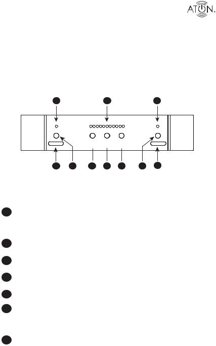
Front Panel
The front panel of the DLA2/4/6 has multiple selector buttons to access rooms and control power and volume states. Blue LEDs display Volume level and Room On status, while red LEDs show that a room is selected for adjustment. Figure 1-2 and Table 1-1 provide descriptions and locations of Front Panel controls and indicators.
Note: This manual will consistently show images of the DLA2 Two Room Speaker Selector. DLA4 and DLA6 models are identical in all respects but have additional Speaker Outputs, Room Select Buttons and Room Indicator LEDs.
.
1 |
2 |
1 |
ROOM 1 


 ROOM 2
3 |
4 |
5 |
6 |
7 |
4 |
3 |
|
Figure 1-2: DLA2/4/6 Front Panel |
|
||||
|
|
Indicator/Button |
Function |
LED |
|
|
|
|
|
|
|
1 |
|
Room Indicator LED |
Room ON - Selected |
Red |
|
|
|
Room ON - NOT Selected |
Blue |
|
|
|
|
|
|
||
|
|
|
Room OFF |
No LED |
|
|
|
|
Room Muted |
Blue (Blinking) |
|
2 |
|
Volume Indicator |
Shows Volume Level for Se- |
Blue |
|
|
|
lected RoomLevel 1 to 11 |
|
|
|
|
|
|
|
|
|
|
|
|
|
|
|
3 |
|
Room Label Location |
Place Label to Identify |
|
|
|
|
Rooms |
|
|
|
|
|
|
|
|
|
4 |
|
Room Select |
Selects Room for |
|
|
|
|
Adjustment |
|
|
|
|
|
|
|
|
|
|
|
|
|
|
|
5 |
|
All ON/All OFF Button |
Turns All Rooms ON or OFF |
|
|
|
|
|
|
|
|
|
|
|
|
|
|
6 |
|
VOL - |
Decreases Volume of Select- |
|
|
|
|
ed Room by One Step-Press |
|
|
|
|
|
|
|
|
|
|
|
|
and Hold to Ramp Volume |
|
|
|
|
|
Down |
|
|
|
|
|
|
|
|
7 |
|
VOL + |
Increases Volume of Select- |
|
|
|
|
ed Room by One Step-Press |
|
|
|
|
|
|
|
|
|
|
|
|
and Hold to Ramp Volume |
|
|
|
|
|
Up |
|
|
|
|
|
|
|
|
|
|
Table 1-1: Front Panel Indicators/Buttons |
|
|
|
|
© 2008 • All rights reserved. |
|
5 |
||

DLA2/4/6 Speaker Level Audio Router
Rear Panel
The Rear Panel of the DLA2/4/6 has connections for Power, Ampli er Input, Sense Inputs, page/Doorbell Trigger Inputs, the RF Receiver (ATON Port), IR Emitter Outputs, IR receiver Inputs and Speaker Outputs. Figure 1-3 and Table 1-2 provide description and location of Rear Panel connections.
|
9 |
8 |
|
|
7 |
6 |
6 |
DLA2 |
|
|
|
|
|
|
|
PATENT |
AMPLIFIER |
IR MITTER OUTPUTS |
|
|
|
|
|
I P |
|
|
|
|
|
|
|
PENDING |
RF |
|
|
|
|
|
|
SENSE |
|
|
|
|
|
||
|
INPUT |
|
|
|
|
|
|
PWR IN |
INPUT |
|
IMPEDANCE |
|
|
||
|
|
|
|
||||
12VDC / 2.1A |
9VDC / 100mA |
|
|
|
MATCH |
|
|
|
|
|
|
8 |
8 |
|
|
|
CLASS 2 WIRING |
PA E |
4 |
4 |
|
|
|
|
RI |
I |
1 |
|
|||
|
|
|
|
|
|
|
|
1 |
2 |
3 |
4 |
5 |
5 |
Figure 1-3 : DLA2/4/6 Rear Panel
Connector Function
112 VDC Power Connector Connector for +12VDC/2.1A (PS3) Power
|
|
Transformer |
|
2 |
Sense Input Connector |
Connector for optional +12 VDC/200mA |
|
|
(PS2) Sense Status Power Transformer |
||
|
|
||
3 |
IR Emitter Outputs |
3.5mm Mono Mini Jack Connectors for Use |
|
|
With ATON IR Emitters |
||
|
|
||
4 |
Page/DB Trigger |
3.5 mm. Stereo Mini-Jack Connector for use |
|
|
with ELAN Communication Controllers or |
||
|
|
||
|
|
equivalent |
|
|
|
|
|
5 |
IR Receiver Inputs |
Flip Lock Connectors for IR receivers or DLA |
|
|
Touchpads. IR receivers allow for individual |
||
|
|
||
|
|
room control or system-wide control using |
|
|
|
DLA discrete IR codes.* |
|
|
|
|
|
6 |
Speaker Outputs |
4-position Fliplock Connectors for 16 |
|
|
Gauge, 4 Conductor (16/4 AWG) Speaker |
||
|
|
||
|
|
Leads to Room Speakers |
|
|
|
|
|
7 |
Impedance Match DIP |
Select The Impedance Value Of the Ampli- |
|
Switches |
er And Speakers, 4 Or 8 Ohms |
||
|
|||
|
|
|
|
8 |
ATON Port |
Connects to Optional RF Receiver |
|
|
|
||
|
|
|
|
9 |
Ampli er/Receiver Input |
4-position Fliplock Connector for 16 Gauge, |
|
|
4 Conductor (16/4 AWG) Speaker Leads |
||
|
|
||
|
|
From Ampli er or A/V Receiver Speaker |
|
|
|
Outputs |
|
|
|
• 125 Watts per Channel Max |
Table 1-2: Rear Panel Connectors
* IR codes available for download at: www.atonhome.com. See Appendix C-3.
6 |
©2008 • All rights reserved. |
DLA2/4/6 Speaker Level Audio Router
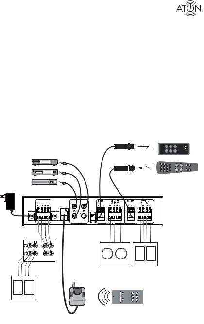
2. System Design Overview
There are four typical system applications when installing the DLA2/4/6:
1.Standard A/V or Stereo Receiver
2.Zone 2 Output of an A/V Receiver
3.External Ampli er
4.Sub-Zone of a Multi-Room Controller
Figure 2-1 shows a DLA2 connected to an A/V receiver with optional ATON accessories including optional AIR3 IR Receivers, AIE2 IR Emitters and a DLA2RKT RF remote Kit. This system is capable of house-wide control of the DLA2 through the RF Kit as well as Room 1 and Room 2 control using the included IR Remote. A universal remote or source remote can be used to control the DLA 2/4/6* as well as the equipment connected to the IR EMITTER OUTPUTS for even more convenience.
|
|
AIR3 |
Included IR |
|
|
IR Receivers |
Remote Control |
|
|
(Optional) |
(Controls DLA2/4/6) |
|
AIE2 |
Room 1 |
|
|
IR Emitters |
|
|
A/V Receiver |
(Optional) |
|
|
DVD |
|
|
|
Satellite |
|
Room 2 |
Universal/Source |
|
|
||
|
|
|
IR Remote Control |
DLA2 |
|
|
|
|
PATENT |
AMPLIFIER |
IR EMITTER OUTPUTS |
|
|
INPUT |
RF |
|
|
|
PENDING |
SENSE |
|
|
|
|
INPUT |
|
|
|
PWR IN |
INPUT |
|
IMPEDANCE |
|
12VDC / 2.1A |
9VDC / 100mA |
|
|
MATCH |
|
|
|
8 |
8 |
|
CLASS 2 WIRING |
PAGE/DB |
|
|
|
TRIGIN |
4 |
4 |
|
|
|
|
|
1 |
|
16/4 |
|
|
16/4 |
|
|
Speaker |
|
|
|
|
|
|
|
Speaker |
|
|
|
Cables |
|
|
|
|
|
|
|
Cables |
|
|
|
|
|
|
|
|
|
L R |
L R |
|
|
|
|
+ |
|
|
|
|
|
- |
|
|
|
|
16/4 |
OUT |
OUT |
|
|
|
Speaker |
|
|
|
|
|
Cables |
A/V Receiver |
Room 1 |
|
Room 2 |
|
|
|
RF |
|
||
|
|
Speakers |
|
Speakers |
|
|
|
Receiver |
|
||
|
|
|
|
|
|
|
|
(Optional) |
|
|
|
|
|
|
ROOM 2 |
VOL + |
- VOL |
|
|
|
ROOM 1 |
SCENE |
MUTE |
|
Main |
|
ALL ON |
ALL OFF |
|
|
|
|
|
|
|
|
Speakers |
DLA2RKT |
|
|
|
|
|
|
|
|
|
|
|
RF Remote Kit |
|
|
|
|
|
(Optional) |
|
|
|
Figure 2-1: System Overview
* DLA discrete IR codes available for download at: www.atonhome.com. See Appendix C-3.
© 2008 • All rights reserved. |
7 |
DLA2/4/6 Speaker Level Audio Router
Standard Audio/Video or Stereo Receiver
Most A/V Receivers and Stereo Receivers have two sets of Main Speaker Outputs (typically labelled “A” and “B”. While it is certainly possible to connect the DLA2/4/6 to the “A” outputs, it is much more useful to connect the “A” outputs to the main speakers (stereo or surround) in the room in which the receiver is located and connect the “B” outputs to the DLA2/4/6 in order to expand the audio system to additional areas. Figure 2-2 shows the “B” speaker outputs
of an A/V receiver connected to to the AMPLIFIER INPUT of the DLA2. A pair of speakers are connected to the DLA2’s Room 1 Speaker Outputs, while an additional pair of speakers is connected to the Room 2 Speaker Outputs. In this scenario, the A/V receiver’s speakers play in the main listening area, while two additional pairs of speakers play in other areas of the home. This is a single-source application: all areas of the house will play the same audio source, but with separately controlled volume.
Note: For best audio quality, ATON recommends that Surround Sound and/or DSP modes (Concert, Hall, Jazz, etc.) be disabled prior to playing audio through the DLA2/4/6.
DLA2 |
|
|
|
|
PATENT |
AMPLIFIER |
IR MITTER OUTPUTS |
|
|
INPUT |
RF |
|
|
|
PENDING |
SENSE |
|
|
|
PWR IN |
INPUT |
|
|
|
INPUT |
|
IMPEDANCE |
||
12VDC / 2.1A |
9VDC / 100mA |
|
|
MATCH |
|
|
|
8 |
8 |
|
CLASS 2 WIRING |
PAGE/DB |
|
|
|
TRIG IN |
4 |
4 |
|
|
|
|
|
1 |
16/4 |
16/4 |
Speaker |
Speaker |
Cables |
Cables |
L R |
L R |
+
-
AB
A/V Receiver
Room 1 |
Room 2 |
Speakers |
Speakers |
(B) |
(B) |
Main
Speakers
(A)
Figure 2-2: DLA2 with A/V Receiver Output B Overview
8 |
©2008 • All rights reserved. |
DLA2/4/6 Speaker Level Audio Router
Zone 2 Output of an A/V or Stereo Receiver
Certain A/V Receivers and Stereo Receivers have a Zone 2 feature that allows them to play a seperate source to a second zone. Figure 2-3 shows the Zone 2 speaker outputs of an A/V receiver connected to to the AMPLIFIER INPUT of the DLA2. Like the previous example, a pair of speakers are connected to the DLA2s Room 1 Speaker Outputs, while an additional pair of speakers is connected to the Room 2 Speaker Outputs. This application allows the A/V receiver’s Main speakers to play in the room in which the receiver is located, while two additional pairs of speakers play in other areas of the home. This is a multi-source application: the Main speakers may play one source, while Zone 2 (the DLA2 locations) plays a different source.
Note: Set the Zone 2 volume level to the point where it achieves the maximum listenable level (prior to distortion). The DLA2/4/6’s volume level will adjust up to this maximum level.
DLA2 |
|
|
|
|
PATENT |
AMPLIFIER |
IR MITTER OUTPUTS |
|
|
INPUT |
RF |
|
|
|
PENDING |
SENSE |
|
|
|
PWR IN |
INPUT |
|
|
|
INPUT |
|
IMPEDANCE |
||
12VDC / 2.1A |
9VDC / 100mA |
|
|
MATCH |
|
|
|
8 |
8 |
|
CLASS 2 WIRING |
PAGE/DB |
|
|
|
TRIG IN |
4 |
4 |
|
|
|
|
|
1 |
16/4 |
|
16/4 |
Speaker |
|
Speaker |
Cables |
|
Cables |
L R |
L R |
|
+ |
|
|
- |
|
|
ZONE 1 |
ZONE 2 |
|
A/V Receiver |
|
|
|
Room 1 |
Room 2 |
|
Speakers |
Speakers |
|
(Zone 2) |
(Zone 2) |
Main
Speakers
(Zone 1)
Figure 2-3: A/V Receiver Zone 2 Application
© 2008 • All rights reserved. |
9 |

DLA2/4/6 Speaker Level Audio Router
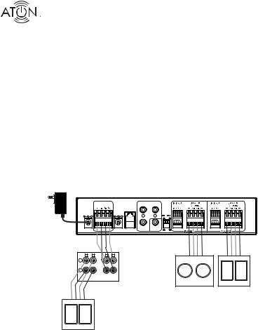
External Ampli er
Some systems utilize an external ampli er for speakers that are connected to the DLA2/4/6. In A/V receiver or stereo receiver applications, a line-level output (Tape Loop, Monitor Out, etc.) is connected to the external ampli er (See Figure 2-4). In a Pre-Amp/Processor-based system, the Pre-Amp is connected to the external ampli er as shown in Figure 2-5.
DLA2 |
|
|
|
|
|
|
|
PATENT |
|
AMPLIFIER |
|
IR MITTER OUTPUTS |
|
|
|
|
INPUT |
RF |
|
|
|
|
|
PENDING |
|
SENSE |
|
|
|
|
|
PWR IN |
INPUT |
|
|
|
|
||
INPUT |
|
|
|
IMPEDANCE |
|||
12VDC / 2.1A |
9VDC / 100mA |
|
|
|
|
MATCH |
|
|
|
|
|
|
|
8 |
8 |
|
|
CLASS 2 WIRING |
|
|
PAGE/DB |
|
|
|
|
|
|
TRIG IN |
4 |
4 |
|
|
|
|
|
|
|
|
1 |
16/4 |
|
|
|
|
|
|
16/4 |
Speaker |
|
|
|
|
|
|
Speaker |
Cables |
|
|
|
|
|
|
Cables |
+ |
- |
- |
+ |
Line-Level |
|
|
|
|
|
|
|
Inputs |
|
|
|
|
L |
R |
|
L |
R |
|
|
Speaker Outputs
Amplifier |
|
RCA |
|
Room 1 |
Room 2 |
|
|
|
|
|
Speakers |
Speakers |
|
|
|
Interconnect |
|
|
|
|
A/V Receiver |
|
Cables |
|
|
|
|
|
|
|
|
|
||
|
Speaker Outputs |
|
|
OUT |
|
|
|
L |
R |
|
|
||
|
L |
R |
|
|||
+ |
- |
- |
+ |
|
||
|
|
|
||||
IN
TAPE
LOOP
Speaker
Cables
Main
Speakers
Figure 2-4: External Ampli er - A/V Receiver Tape Loop Application
10 |
©2008 • All rights reserved. |

DLA2/4/6 Speaker Level Audio Router
DLA2 |
|
|
|
|
|
|
|
PATENT |
|
AMPLIFIER |
|
IR MITTER OUTPUTS |
|
|
|
|
INPUT |
RF |
|
|
|
|
|
PENDING |
|
SENSE |
|
|
|
|
|
PWR IN |
INPUT |
|
|
|
|
||
INPUT |
|
|
|
IMPEDANCE |
|||
12VDC / 2.1A |
9VDC / 100mA |
|
|
|
|
MATCH |
|
|
|
|
|
|
|
8 |
8 |
|
|
CLASS 2 WIRING |
|
|
PAGE/DB |
|
|
|
|
|
|
TRIG IN |
4 |
4 |
|
|
|
|
|
|
|
|
1 |
16/4 |
|
|
|
|
|
|
16/4 |
Speaker |
|
|
|
|
|
|
Speaker |
Cables |
|
|
|
|
|
|
Cables |
+ |
- |
- |
+ |
Line-Level |
|
|
|
|
|
|
|
Inputs |
|
|
|
|
L |
R |
|
L |
R |
|
|
Speaker Outputs
Amplifier |
RCA |
Room 1 |
Room 2 |
|
Speakers |
Speakers |
|
|
Interconnect |
|
|
|
Cables |
|
|
LR
Line-Level
Outputs
Pre-Amp/Processor
Figure 2-5: Processor/Pre-Amp - Ampli er Application
© 2008 • All rights reserved. |
11 |
 Loading...