


A275
Two-Channel Power Ampli er
INSTALLATION MANUAL
P/N 9803392 REV:B

ATON
A275 INSTALLATION MANUAL
Preface
Purpose of This Manual
This manual provides step-by-step installation instructions and connection examples, along with basic user information for installation and ongoing use of the A275 Two-Channel Power Amplifier. This manual is written for the installer of this equipment.
Organization
The following information is contained in this manual:
Safety Information Provides a comprehensive list of safety practices and procedures allowing for the safe
installation and operation of ATON's A275 Two-Channel Power Amplifier.
A275 Introduction Provides an introduction to the A275 Two-Channel Power Amplifier, along with system
features to include Front and Rear panel controls, indicators and connections, along with
a short description of each.
A275 System Design Overview Provides a system design application overview of the A275 Two-Channel Power Amplifier
for use in audio applications.
A275 Connections Provides a description of A275 Two-Channel Power Amplifier connections including
connections made with ATON Multi-Room Systems and direct connections to the A275
Two-Channel Power Amplifier from other components.
Troubleshooting Provides troubleshooting tables to help fix common discrepancies that may
be associated with the A275 Two-Channel Power Amplifier.
Specifications Appendix A provides equipment specifications for the A275 Two-Channel Power Amplifier.
Rack Mounting Appendix B provides specifications for Rack Mounting of the A275 Two-Channel Power
Amplifier using the included rack mount brackets.
© ATON 2010 • All rights reserved. Page I

A275 INSTALLATION MANUAL
RISK OF ELECTRIC SHOCK
DO NOT OPEN!
WARNING
CAUTION: TO REDUCE THE RISK OF ELECTRIC SHOCK, DO NOT
REMOVE COVER (OR BACK). NO USER SERVICEABLE PARTS INSIDE.
REFER SERVICING TO QUALIFIED SERVICE PERSONNEL.
WARNING: TO REDUCE THE RISK OF FIRE OR SHOCK,
DO NOT EXPOSE THIS APPLIANCE TO RAIN OR MOISTURE.
The lightning flash with arrowhead symbol within an equilateral triangle is intended to
alert the user to the presence of uninsulated "dangerous voltage" within the product's
enclosure that may be of sufficient magnitude to constitute a risk of electric shock to persons.
The exclamation point within an equilateral triangle is intended to alert the user to the presence
of important operating and maintenance (servicing) instruction in the literature accompanying
the appliance.
CAUTION
CAUTION: RISK OF EXPLOSION IF BATTERY IS REPLACED BY AN
INCORRECT TYPE. DISPOSE OF USED BATTERIES ACCORDING TO
THE INSTRUCTIONS.
ATON
IMPORTANT SAFETY INFORMATION
Read Information—All the safety and operating information should be read before the appliance is operated.
Follow Information—All operating and use information should be followed.
Retain Information—The safety and operating information should be retained for future reference.
Heed Warnings—All warnings on the appliance and in the operating instructions should be heeded.
Wall Mounting—Mounting of this appliance should be done only by an authorized installer.
Ventilation—The appliances should be situated so that their location or position does not interfere with their proper ventilation. These appliances should never be
placed near or over a radiator or heat register. These appliances should not be placed in a built-in installation such as a bookcase or cabinet that may impede the flow of
air through the ventilation openings.
Non-Use Periods—Appliances that are left unattended and unused for long periods of time should be de-energized.
Power Sources—The appliances should be connected to a power supply only of the type described in the operating instructions or as marked on each appliance.
If you are not sure of the type of power supply to your home, consult your authorized ATON dealer or local power company.
Grounding or Polarization—Do not defeat the safety purpose of the polarized or grounding-type plug. A polarized plug has two blades with one blade wider
than the other blade. A grounding type plug has two blades and a third grounding prong. The polarized wide blade and the third prong are provided for your safety. If
the provided plug does not fit your outlet, consult an electrician for replacement of the obsolete outlet.
Water and Moisture—To reduce the risk of electric shock or fire, these appliances should not be used near water ––for example, near a bathtub, washbowl,
kitchen sink, laundry tub, in a wet basement, or near a swimming pool.
Power Cord Protection—Protect the power cord from being walked on or pinched particularly at plugs, convenience receptacles and the point where they exit
from the apparatus.
Telephones—Avoid using a telephone (other than a cordless type) during an electrical storm. There may be a remote risk of electrical shock from lightning. Do not
use a telephone to report a gas leak if the leak is in the vicinity of the ATON electronic equipment because of risk of fire or explosion.
Page II © ATON 2010 • All rights reserved.

ATON
®
US
C
ELECTRIC
SERVICE
EQUIPMENT
GROUND
CLAMPS
POWERSER VICE GROUNDING
ELECTRODESYSTEM
(CECSECTION 10-700)
ANTENNA
LEAD-IN WIRE
GROUND CLAMPS
GROUNDING CONDUCTORS
(CECSECTION 54-200)
ANTENNA LEAD-IN WIRE
(CECSECTION 54-200)
NE C-NAT IONAL ELECTRICAL CODE
(NEC SECTION 810-20)
(NEC SECTION 810-21)
(NEC AR TICLE 250, PA RT H)
CE C-CANADIAN ELECTRICAL CODE
Grounding
Diagram
US
C
US
C
A275 INSTALLATION MANUAL
Cleaning—Unplug the apparatus from the power outlet before cleaning. Use only a dry cloth to clean the apparatus.
Power Lines—An outdoor antenna should be located away from power lines. When installing an outside antenna system, extreme care should be taken to avoid
touching power lines or circuits, as contact with them may be fatal.
Outdoor Antenna Grounding—If an outside antenna or cable system
is connected to these audio products, be sure the antenna or cable system is grounded
so as to provide some protection against voltage surges and built-up static charges. Section 810 of the U.S. National Electrical Code, and Section 54 of the
Canadian Electrical Code, provide information with respect to proper grounding of
the mast and supporting structure, grounding of the lead-in wire to an antenna
discharge unit, size of grounding conductors, location of antenna-discharge unit,
connection to grounding electrodes, and requirements for the grounding electrode.
See the grounding diagram (right).
Overloading—Do not overload wall outlets and extension cords, as this could
result in fire or electric shock.
Object and Liquid Entry—Never insert objects of any kind through the
openings of these appliances, as they may touch dangerous voltage points or
short-out parts that could result in a fire or electric shock. Care should be taken so that
objects do not fall and liquids are not spilled into the appliance through openings in the enclosure.
Servicing—Do not attempt to service these appliances yourself, as opening or removing covers may expose you to dangerous voltage or other hazards. Refer all
servicing to qualified service personnel.
Damage Requiring Service—These appliances should be serviced by qualified service personnel when:
• A power supply connection or a plug has been damaged or
• If liquid has been spilled into the appliance or objects have fallen into the appliance or
• The appliance has been exposed to water or moisture or
• The appliance does not appear to operate normally or exhibits a marked change in performance or
• The appliance has been dropped or the enclosure damaged.
Replacement Parts—When replacement parts are required, be sure the service technician has used replacement parts specified by the manufacturer or that
have the same characteristics as the original part. Unauthorized substitutions may result in fire, electric shock, or other hazards. The Master Control Unit battery should be
replaced only after turning the power off and only by an authorized installer.
Safety Check—Upon completion of any service or repairs to this audio product, ask the service technician to perform safety checks to determine that the audio
product is in proper operating condition.
Lightning Storms—Unplug this apparatus during lightning storms or when unused for long periods of time.
Attachments and Accessories—Use only attachments/accessories specified by the manufacturer.
Cart, Stand, Tripod, Bracket or Table—Use only with a cart, stand, tripod, bracket or table specified by the manufacturer, or sold with the apparatus.
When a cart is used, use caution when moving the cart/apparatus combination to avoid injury from tip over.
Disconnect Device—Where the mains plug or an appliance coupler is used as the disconnect device, the disconnect device shall remain operable.
© ATON 2010 • All rights reserved. Page III

A275 INSTALLATION MANUAL
ATON
Page IV © ATON 2010 • All rights reserved.

ATON
A275 INSTALLATION MANUAL
Table of Contents
Purpose of This Manual .................................................................................................................................................................................................................................................................................................................................................................................................................................................................................................................................I
Organization ............................................................................................................................................ I
Safety Information .................................................................................................................................. I
Chapter 1: Introduction
Introduction ........................................................................................................................................... 1
A275 Features ..................................................................................................................................................1
A275 Functions & Indicators
Front Panel .......................................................................................................................................................................................2
Rear Panel .................................................................................................................................................... 2
........................................................................................................................................................2
Chapter 2:
A275 System Design Overview
System Design
Wiring Considerations .................................................................................................................................... 3
Applications ..............................................................................................................................................................................3-5
Amp and Speaker Selector Applications ................................................................................................3-4
Volume Control Applications .................................................................................................................... 5
Multi-Room Applications ......................................................................................................................6-7
Chapter 3:
A275 Connections
Connections
Line Inputs ................................................................................................................................................... 8
Line Output ................................................................................................................................................... 9
Speaker Connections .................................................................................................................................. 10
Triggers ...................................................................................................................................................... 11
Chapter 4:
Chapter 5:
Appendix A: Specifications
Operations and Settings ............................................................................................................. 12
Troubleshooting .....................................................................................................................13-14
............................................................................................................................ 15
Appendix B: Rack Mounting
Warranty
© ATON 2010 • All rights reserved. Page V
......................................................................................................................................................... 20
......................................................................................................................16-17

A275 INSTALLATION MANUAL
ATON
A275
Power Ampli er
Items in package:
A275 Two-Channel Power Amplifier•
Rack Mount Brackets•
Installation Manual•
Page VI © ATON 2010 • All rights reserved.

ATON
A275 INSTALLATION MANUAL
Chapter 1: Introduction
Thank you for purchasing the ATON A275 Two-Channel Power Amplifier. Soon you will be experiencing the quality and reliability we
place in all of our products. The backbone of any distributed audio system is the amplification. The true test of any amplifier is the ability to drive multiple speakers at low impedance for hours on end. In this arena, the A275 excels! Heat is the number cause for amplifier
failure, or temporary audio loss from thermal shutdown protection circuitry, a.k.a. overheating. Of course that typically happens when
you are entertaining a house full of guests! ATON designed the A275 with 2 long rows of external cooling fins to increase the heat dissipation capability. Higher cooling capacity equals longer product life, cleaner audio signal, and of course, more satisfied customers!
A275 Features
• 2 x 45 Watts per Channel @ 8 Ohms
• 2 x 75 Watts per Channel @ 4 Ohms
Buffered Line Outputs
• Allow the signal to be sent to other A275 amplfiers, A/V receivers, etc.
System Trigger In/Out
• SYSTEM TRIGGER IN allows all channels of the amplifier to UNMUTE when a signal is received.
• SYSTEM TRIGGER OUT sends a +12VDC pulse whenever any of the channels of the amplifier are UNMUTED.
Individual Channel Level Adjustment
• Fine-tune each channel’s level using precision potentiometers.
5-Way Speaker Binding Post
• The A275 is equipped with gold plated, 5-way speaker binding posts. This allows for five methods of speaker wire termination:
bare wire, Spade lug, pin, single banana and dual banana plug.
Safety Concerns
Use only grounded outlets when powering this product. Making any modification to the power cord could cause unsafe operation and
will void the manufacturer’s warranty.
AC Power Considerations
The A275 requires 3.7 Amps of AC current. When designing any whole house system using multichannel amplifiers, make sure to
provide adequate provisions for all electronic equipment to be installed. This may require additional outlets and/or circuit breakers to
be installed. Consult a licensed electrician in this case.
© ATON 2010 • All rights reserved. Page 1

A275 INSTALLATION MANUAL
FRONT
1
2
1
2
3
BACK
1
2
3
4
5
}
6
A275 Front Panel Functions and Indicators
ITEM FUNCTION
ATON
Figure 1-1: A275 Front Panel
Table 1-1:Front Panel
1
2
A275 Back Panel
Channel Gain Potentiometers (2)
POWER LED Glows blue when power switch is ON and unit is plugged in.
2
Item Function
Channel Gain Potentiometers (2)
ITEM FUNCTION
Pull-Out Access Door
1
POWER LED - Glows Blue When Power Switch is ON and Unit Plugged In
POWER SWITCH
Figure 1-2: A275 Back Panel
Table 1-2: Back Panel
2
3
4
5
6
Page 2 © ATON 2010 • All rights reserved.
POWER CORD
SPEAKER OUTPUTS
SYSTEM TRIGGER IN/OUT
LINE OUTPUTS
LINE INPUTS

ATON
HOME THEATER RECEIVER
A275
RL
Line Level
Analog Audio
Output
DLA4 SPEAKER SELECTOR
AMPLIFIER
INPUTS
SPEAKER
OUTPUTS
SPK
SPK
SPK
SPK
SPK
SPK
SPK
SPK
HOME THEATER RECEIVER
Line Level
8Ω 8Ω
4Ω 4Ω
8Ω 8Ω
4Ω 4Ω
A275 Speaker Outputs
DLA Speaker Inputs
RED
BLACK
WHITE
GREEN
W G B R
A275 INSTALLATION MANUAL
Chapter 2. System Design & Applications
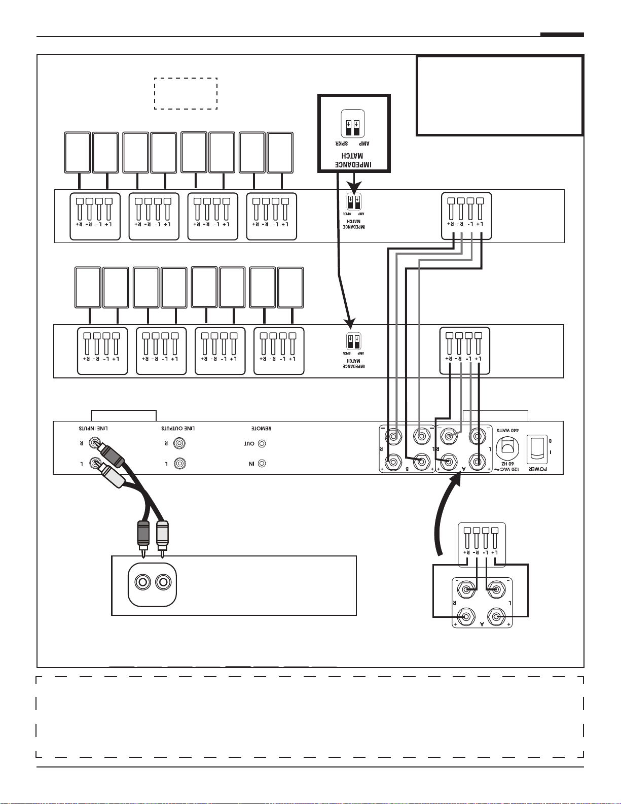
System Design
The A275 is designed to drive multiple pairs of indoor or outdoor speakers from virtually any audio source. A typical installation consists of a home theater receiver zone 2 or zone 3 line level output feeding the A275. The A275 amplified outputs can drive speakers,
volume controls, or ATON DLA speaker routers depending upon the application. The advantage of using a DLA along with the A275 is
the ability to drive multiple pairs of speakers while enjoying the benefits of the DLA Router: automatic impedance protection, dynamic
volume level adjustment, discrete IR remote control, and RF remote control. The A275 is designed to drive one or more DLA’s including
the DLA2, DLA4, or DLA6. If you need additional DLA configuration and setup assistance, please refer to the DLA installation manual.
Wiring Considerations
Speaker Wires Audio Cables Triggers
14-16 AWG Speaker Wire RCA Patch Cables 2 Conductor Wires with 3.5mm mono connector
SETTING UP THE A275 WITH A DLA SPEAKER SELECTOR
(DLA2, DLA4, or DLA6 can be used)
IMPORTANT!
In this application, the DLA's
"AMP" switch should be in the
down or "4" Ohm position. Set
the "SPKR" switch to the "4" or
"8" Ohm position depending on
the impedance of the speakers
being used.
© ATON 2010 • All rights reserved. Page 3
Figure 2-1: A275 and DLA SPEAKER SELECTOR

A275 INSTALLATION MANUAL
A275 Speaker Outputs
DLA Speaker Inputs
RED
BLACK
WHITE
GREEN
W G B R
AMPLIFIER
INPUTS
SPEAKER
OUTPUTS
SPK
SPK
SPK
SPK
SPK
SPK
SPK
SPK
HOME THEATER RECEIVER
A275
RL
Line Level
Analog Audio
Output
DLA4 SPEAKER SELECTOR 1
AMPLIFIER
INPUTS
SPEAKER
OUTPUTS
SPK
SPK
SPK
SPK
SPK
SPK
SPK
SPK
DLA4 SPEAKER SELECTOR 2
AMPLIFIER
INPUTS
SPEAKER
OUTPUTS
SPK
SPK
SPK
SPK
SPK
SPK
SPK
SPK
8Ω 8Ω
4Ω 4Ω
8Ω 8Ω
4Ω 4Ω
8Ω 8Ω
4Ω 4Ω
8Ω 8Ω
4Ω 4Ω
8Ω 8Ω
4Ω 4Ω
Wiring Considerations
Speaker Wires Audio Cables Triggers
14-16 AWG Speaker Wire RCA Patch Cables 2 Conductor Wires with 3.5mm mono connector
SETTING UP THE A275 WITH MULTIPLE DLA SPEAKER SELECTORS
ATON
(DLA2, DLA4, or DLA6 can be used)
(DLA2, DLA4, or DLA6 can be used)
IMPORTANT!
In this application, the DLA's
"AMP" switch should be in the
UP or "8" Ohm position. Set the
"SPKR" switch to the "4" or "8"
Ohm position depending on the
impedance of the speakers being
used.
Page 4 © ATON 2010 • All rights reserved.
Figure 2-2: A275 and MULTIPLE DLA SPEAKER SELECTORS

ATON
A275
RL
Line Level
Analog Audio
Output
Speakers
Speakers
ATON
VOLUME
CONTROL
AVC100R
or AVC100SL
Applications
4/6/8 Ohm Speakers with Volume Controls
• Audio Output to Line Inputs 1 & 2
A275 INSTALLATION MANUAL
Figure 2-3: 4/6/8 Ohm Speakers w/ Volume Controls
Using A275 with Impedance Match Volume Controls and Maximum Speaker Wattage
Volume Control
Impedance Match Setting
8 Ohm
Speaker Pairs
Max Wattage
Available Per
Speaker
6 Ohm
Speaker Pairs
Max Wattage
Available Per
Speaker
4 Ohm
Speaker Pairs
Max Wattage
Available Per Speaker
1X 4 18.0 3 24.0 2 36.0
2X 6 12.0 4 18.0 3 24.0
4X 8 6.0 6 9.0 4 12.0
8X 16 1.0 12 1.5
NOT RECOMMENDED
System Design Considerations
Adding multiple speakers to a power amplifier reduces the amount of power sent to each speaker as the total available wattage is
divided among the connected speakers. Beyond customer volume preferences, several factors affect overall amplifier output including
input signal gain, impedance, AC voltage, wire run length and gauge, insertion losses with volume controls, room size, etc. This chart
assumes simple math and does not represent actual dB, SPL calculations, etc. It is provided as a guideline only to demonstrate theory
& provide some basic design guidance. You can never overpower a system because you have dynamic headroom, or spare power as
needed. If you underpower / underamplify a system, the amplifier tends to be pushed past its safety zone which eventually leads to
clipping and system failure.
Indoor applications for background audio need only be a few watts, typically 1 to 10. For primary listening areas, you should plan on 5
to 20 watts or more depending upon application. Outdoor applications require a greater amount of power since there is little reflectivity
of sound and listening area is larger, so plan on 40 watts or more!
© ATON 2010 • All rights reserved. Page 5

A275 INSTALLATION MANUAL
A275
AH66T MULTI-ROOM CONTROLLER
Variable (UP)
Speakers
Speakers
ATON
VOLUME
CONTROL
AVC100R
or AVC100SL
ATON
Multi-Room
Stereo Sub-Zones
ATON’s AH66T Integrated Multi-Room Controller has built-in amplification for six stereo zones as well as six sets of preamp outputs for
the addition of sub-zones. The A275 is ideally suited to amplify outdoor subzones using rotary or electronic volume controls if separate
volume up/down functionality is desired in the sub-zones as shown in the AH66T example below.
AH66T Stereo Sub-Zones
• Preamp Output 1 & 2 to Line Inputs 1 & 2
• Preamp DIP Switches in VARIABLE Position
Each Zone and Sub-Zone Speakers Volume Ramps Together
Figure 2-4: AH66T Sub-Zones
Please see chart on previous page for impedance match settings and volume controls
IMPORTANT NOTE
Page 6 © ATON 2010 • All rights reserved.

ATON
A275
AH66T MULTI-ROOM CONTROLLER
Fixed (DOWN)
Outdoor
Speakers
Outdoor
Speakers
ATON
VOLUME
CONTROL
AVC100R
or AVC100SL
AH66T Stereo Sub-Zones
• Preamp Output 1 & 2 to Line Inputs 1 & 2
• Preamp DIP Switches in FIXED Position
• Volume Controls on Each Speaker Output
Each Zone and Sub-Zone Has Independent Volume Control
A275 INSTALLATION MANUAL
Figure 2-5: AH66T Sub-Zones
IMPORTANT NOTE
Please see chart on previous page for impedance match settings and volume controls
© ATON 2010 • All rights reserved. Page 7

A275 INSTALLATION MANUAL
A275
From Audio
Output Source
RCA Patch
Cable
ATON
Chapter 3: Connections
The A275 has several rear panel connections so it is important to label all cables and wires correctly. Label all input/output cable and
speaker wires with their destination or source. This will save time during installation and any future upgrades to the system.
Use high quality line level RCA connector type cables for source connections to ensure the lowest possible noise and best sound performance. For most applications use 16AWG 2 conductor speaker cable. For wiring runs longer than 80 ft. it is recommended to use
14AWG 2 conductor speaker cable. The A275's high quality, gold plated 5-way binding post will accommodate speaker cabling sizes up
to 12AWG. Attaching banana plugs will enable the connection of larger cable sizes. A 3.5mm mono interconnect cable may be used for
amplifier and systems triggering.
Line Level Audio Inputs
Connect the zones by inserting the RCA connectors into the dedicated direct input jack on each channel.
Figure 3-1: Line Inputs
Page 8 © ATON 2010 • All rights reserved.

ATON
A275 #1
From Audio
Output Source
RCA Patch
Cable
A275 #2
RCA Patch
Cable
To A275s
#3-4
A275 INSTALLATION MANUAL
Line Ouputs
A stereo or monaural audio signal connected to the A275’s main LINE INPUT is routed to the A275’s RCA Line Outputs. This feature is
excellent for standalone distributed audio systems where one source (i.e. an A/V Receiver) is providing audio to the entire home, and also
for ATON multi-room applications where a zone’s audio signal needs to be routed to multiple amplifier channels. Examples of both these
applications are shown in the Chapter 2.
Line audio outputs enable connection of additional amplifiers to allow further system expansion. Use high quality RCA interconnect
cables to ensure low noise and great sound. The A275 Line Outputs are buffered, a maximum of four amplifiers may be 'daisy-chained'
to each Line Outputs.
Figure 3-2: Line Outputs
© ATON 2010 • All rights reserved. Page 9

A275 INSTALLATION MANUAL
Banana Plugs
Speaker Wire
A275 Amplifier
Binding Post
WARNING: Do not allow any strands
of the bare speaker wire to touch
the Amplifier Chassis or another
Connector.
Speaker Wire
1/2’
WHITE
GREEN
RED
BLACK
ATON
Speaker Binding Post
The A275 is equipped with gold plated, 5-way speaker binding posts. This allows five methods of speaker wire termination: bare wire,
spade lug, pin, single banana and dual banana plug. Label all speaker wires with their destination to ensure easy configuration. To attach
speaker wires use the following method:
1. Carefully split the speaker wire insulation at least two inches.
2. Strip 1/2 inch of the insulation from the speaker wire conductor exposing the bare wire.
3. Twist the wire strands of each conductor, if using banana plugs, attach wire to banana plug observing polarity.
4. If using banana plug; insert plug ends into binding post observing correct polarity. If using the bare wire method; loosen the
binding post caps and insert the bare wire through the hole in the post. Tighten the knob until the wire is securely clamped.
CAUTION! Speaker Wire connections must be made with the amplifier OFF!
Figure 3-3: Speaker Binding Post
Page 10 © ATON 2010 • All rights reserved.

ATON
3.5mm mono interconnect cable
A275 #1
A275 #2
3.5mm mono interconnect cable
From AH66T
To A275’s
#3-4
A275 INSTALLATION MANUAL
Triggers
A REMOTE TRIGGER IN port allows all channels to turn on or mute simultaneously. The REMOTE TRIGGER INPUT can receive 5-24 Volts
AC or DC. The 12 Volt DC REMOTE TRIGGER OUT can be used to turn on other equipment, additional A275s or other amplifiers, or to
perform automated functions desired by the user. Use 3.5mm mono interconnect cables to make Trigger connections.
SYSTEM TRIGGER IN
To mute/un-mute all channels simultaneously, connect a system-wide 5-24 Volt DC triggering source to the SYSTEM TRIGGER IN port
using a 3.5mm mono interconnect cable. Examples of triggering sources include an ATON Multi-Zone Controller’s SYSTEM
TRIGGER OUT or REMOTE OUT, an A/V receiver’s switched outlet connected to a power supply, or a +12VDC TRIGGER OUT from another
ATON amplifier.
Figure 3-4: Remote Trigger In
SYSTEM TRIGGER OUT
Whenever the A275 is powered ON, the REMOTE TRIGGER OUT becomes active. This output sends a +12VDC 100mA signal to other
devices with a Trigger Input.
© ATON 2010 • All rights reserved. Page 11
Figure 3-5: Remote Trigger Out

A275 INSTALLATION MANUAL
1 2
LEVEL LEVEL
Factory
Default 50%
ATON
Chapter 4: Operations & Settings
Setting Channel Levels
The A275 features independent Level Adjustment Potentiometers for each of its two channels. Use a small Phillips screwdriver to independently adjust each channel of the amplifier for the specific speakers and environmental conditions of the area it is powering. Turning
the potentiometer clockwise increases the level, while turning it counter-clockwise decreases the level. Factory default is 85%.
Set the levels by first lowering them all the way down, then raise the volume of any keypads or volume controls to maximum. Slowly
increase the level of the channel being adjusted by turning the potentiometer clockwise until the channel begins to distort, then reduce the
level slightly (turn counter-clockwise) until distortion is no longer present. Follow this procedure for each channel.
Factory Default
is 85%
Figure 4-1: Level Adjustment Potentiometers
Page 12 © ATON 2010 • All rights reserved.

ATON
Chapter 5: Troubleshooting
Symptom Possible Cause Solution
No Audio From One or
More Channels
1. Loose/bad speaker cable connection
1. Check cable ends at binding posts and
speaker terminals.
A275 INSTALLATION MANUAL
2. Break/short in speaker cable
3. Speaker is defective
4. RCA patch cable defective
5. Source not sending audio
No Audio From One Channel Amplifier is overheating due to
inadequate ventalation or prolonged operation at clipping levels.
No Audio From One Channel Unit may require service. Contact ATON Technical Support.
Very Low or No Sound on Some or All
Channels
Audio input cable is bad. Check source equipment cables for damage
2. Check continuity of each speaker cable
using multimeter. If short or open is indicated, check wiring for proper connections.
3. Swap with known good speaker.
4. Swap with known good patch cable.
5. Verify source is powered up and playing.
Check any tape monitor settings on A/V
Receiver.
1. (a) Turn the amplifier off and allow the
internal circuits to cool.
(b) Ensure that the amplifier has proper
ventilation. Add cooling fan if necessary.
(c) Lower the gain level controls for that
channel pair.
and faulty connections and correct.
Audio “Hum” 1. Ground potential difference between
source components (ground loop)
2. Faulty/damaged cables
3. Faulty wiring
1. (a) Test AC outlet using ground tester.
(b) Reverse the AC plug of components
with non-polarized ends plugged into the
same outlet strip as amp.
2. Check source equipment cables for damage and faulty connections.
3. (a) Make sure volume controls are not
hooked up backwards.
(b) Check for shorts in wiring (see item
2 in “No audio…”).
© ATON 2010 • All rights reserved. Page 13

A275 INSTALLATION MANUAL
Symptom Possible Cause Solution
Distorted Audio at Normal
Volume Levels
1. Input gain set too high
2. Defective/incompatible speaker
3. Volume control wired incorrectly
4. Volume control Impedance Match
settings incorrect
1. Reduce gain to the channel in question.
2. (a) Check for physical damage to
speaker.
(b) Ensure speakers have appropriate
power rating for amplifier.
(c) Ensure speakers are rated @ 8 Ohm
impedance. This amp is compatible with
speakers with 8 Ohm impedance or greater.
3. Check for proper input/output connections at volume control. Input comes from
amplifier, output goes to speakers.
4. Verify/correct Impedance Match settings.
ATON
Audio is Unclear, Bass
Response Low
Incorrect Source Playing
on Speakers
Amplifier Will Not
Power Up
Speakers out of phase Verify that + of amplifier goes to +of speak-
er and - of amplifier goes to - of speaker
on ALL speaker leads.
1. Source connected to wrong
input of amplifier
2. Speakers connected to incorrect
speaker outputs
3. DIP switches set incorrectly
1. Power switch is Off
2. Circuit breaker tripped
1. Verify/correct input connections.
2. Verify/correct speaker connections.
3. Verify/correct DIP switch settings.
1. Turn switch On. Switch is located on the
back of unit.
2. Reset circuit breaker. Ensure that combined current draw of all devices on circuit
does not exceed the circuit’s capacity.
Technical Support
If, after carefully following the steps in the Troubleshooting section, you are unable to
resolve issues with the installation or operation of the A275, please call ATON Technical
Support at 1 (859) 422-7137 Option 3.
Page 14 © ATON 2010 • All rights reserved.

ATON
Appendix A: Specifications
Audio Section
A275 INSTALLATION MANUAL
Power Rating - Output Power
Frequency Response
Full Power Bandwidth
Signal-To-Noise
Channel Separation
Total Harmonic Distortion
Intermodulation Distortion
Voltage Gain (AV)
Input Impedance
Connectors
Input/Loop Outputs
Speaker Outputs
Power
2 x 45 WPC @ 8 Ohms
2 x 75 WPC @ 4 Ohms
20Hz to 20kHz, -.5dB
5Hz to 30kHz
> 110dB (A-weighted)
>70dB @1kHz
< .01% @ 1kHz
< -90dB
0 - 28, front panel adjustable
33k Ohms
Gold RCA Phono
Gold 5 Way Binding Posts
AC Power Requirements
Current Draw
120 VAC, 440 Watts
3.7A @120VAC
Triggers
Remote Trigger Inputs 5 to 24V AC/DC
Remote Trigger Outputs +12 VDC @0.1A
Dimensions/Weight
Dimensions w/ Feet (1U w/o Feet)
Weight
17 W x 2 3/8 H x 11 D (in)
432 W x 60 H x 280 D (mm)
15 lbs/6.8 kg
© ATON 2010 • All rights reserved. Page 15

A275 INSTALLATION MANUAL
ATON
Appendix B: Rack Mounting
Rack-Mount Bracket
When mounting the A275 amplifier in an equipment rack, use the included rack mount brackets for secure mounting and proper ventilation. The A275 requires one rack space, ensure that one rack space above and below the A275 is left open for proper ventilation.
To install the A275 into a standard 19” equipment rack:
1. Slide the rack mount kit onto the A275 chassis from the front as shown in Figure B-1.
Figure B-1
2. Ensure that the unit is flush with the front of the mounting kit. Install each of the eight screws (included) through the side mounting
flanges into the holes in the sides of the unit as shown in Figure B-2. Hand tighten screws! Over-tightening could cause damage
to the A275 Amplifier.
Figure B-2
Page 16 © ATON 2010 • All rights reserved.

ATON
19" Equipment Rack
Rack Screws
3. Once the unit is securely mounted, install the entire assembly into a standard 19” equipment rack from the front using four rack
screws (not included) as shown in Figure B-3.
A275 INSTALLATION MANUAL
Figure B-3
© ATON 2010 • All rights reserved. Page 17

A275 INSTALLATION MANUAL
NOTES:
ATON
Page 18 © ATON 2010 • All rights reserved.

ATON
NOTES:
A275 INSTALLATION MANUAL
© ATON 2010 • All rights reserved. Page 19

LIMITED WARRANTY
Aton (“ATON”) warrants the ATON A275 Two-Channel Power Amplifier to be free from defects in materials and workmanship for the period of two years (2 years) from the date of purchase. If within the applicable warranty period the
purchaser discovers that such item was not as warranted above and promptly notifies ATON in writing, ATON shall
repair or replace the item at the company’s option. This warranty shall not apply (a) to equipment not manufactured
by ATON, (b) to installed equipment which is not installed to ATON’s specifications, (c) to equipment which shall have
been repaired or altered by others than ATON, (d) to equipment which shall have been subjected to negligence, accident, or damaged by circumstances beyond ATON’s control, including, but not limited to, lightning, flood, electrical
surge, tornado, earthquake, or other catastrophic event beyond ATON’s control, or to improper operation, maintenance
or storage, or to other than normal use of service. With respect to equipment sold by, but not manufactured by ATON,
the warranty obligations of ATON shall in all respects conform to the warranty actually extended to ATON by its supplier.
The foregoing warranties do not cover reimbursement for labor, transportation, removal, installation or other expenses
which may be incurred in connection with repair or replacement.
Except as may be expressly provided and authorized in writing by ATON, ATON shall not be subject to any other obligations or liabilities whatsoever with respect to equipment manufactured by ATON or services rendered by ATON.
THE FOREGOING WARRANTIES ARE EXCLUSIVE AND IN LIEU OF ALL OTHER EXPRESSED AND IMPLIED WARRANTIES EXCEPT WARRANTIES OF TITLE, INCLUDING BUT NOT LIMITED TO IMPLIED WARRANTIES OF MERCHANTABILITY AND FITNESS FOR A PARTICULAR PURPOSE.
ATTENTION: TO OUR VALUED CONSUMERS
To ensure that consumers obtain quality pre-sale and after-sale support and service, ATON products are sold exclusively
through authorized dealers, ATON products are not sold online. The warranties on ATON products are NOT VALID if the
products have been purchased from an unauthorized dealer or an online E-tailer. To determine if your ATON reseller is
authorized, please contact ATON at (859) 422-7137 Option 3
www.atonhome.com

P/N 9803392 REVB
www.atonhome.com
llame a ATON al (859) 422-7137, opción 3
distribuidor no autorizado o en una tienda en línea. Para saber si su distribuidor de productos ATON está autorizado,
den a través de Internet. Las garantías de los productos ATON NO SON VÁLIDAS si los productos son comprados a un
productos ATON son vendidos exclusivamente a través de distribuidores autorizados. Los productos ATON no se venPara asegurar que los consumidores obtengan un servicio y una asistencia antes y después de venta de calidad, los
ATENCIÓN: A NUESTROS ESTIMADOS CONSUMIDORES
COMERCIABILIDAD Y APTITUD PARA UN OBJETIVO EN PARTICULAR.
IMPLÍCITA EXCEPTO GARANTÍAS DE TÍTULO, QUE INCLUYA, SIN LIMITARSE A ELLO, GARANTÍAS IMPLÍCITAS DE
GARANTÍAS PRECEDENTES SON EXCLUSIVAS Y REEMPLAZAN A CUALQUIER OTRA GARANTÍA EXPRESA E
LAS
cionados por ATON.
ación o responsabilidad en relación al equipo fabricado o los servicios propor
A menos que se estipule expresamente y que ATON lo autorice por escrito, ATON no estará sujeto a ninguna otra oblig-
de la reparación o sustitución.
no cubren reembolsos por mano de obra, transporte, retiro, instalación u otros gastos en los que se incurra con motivo
ATON se ajustarán en todos los sentidos a la garantía extendida a ATON por su proveedor. Las garantías precedentes
En lo que respecta a los equipos vendidos por ATON pero no fabricados por éste, las obligaciones de la garantía de
ATON, o debido a manejo, mantenimiento o almacenamiento inadecuado, o a usos de servicio que no son los normales.
pagos, inundaciones, alzas de voltaje, tornados, terremotos u otros eventos catastróficos que escapan al control de
de negligencias, accidentes o daños por circunstancias que escapan al control de ATON, incluyendo entre otros, relám(c) a equipos que hayan sido reparados o alterados por personas ajenas a ATON, (d) a equipos que hayan sido objeto
equipos no fabricados por ATON, (b) a equipos que no hayan sido instalados siguiendo las especificaciones de ATON,
escrita, ATON reparará o reemplazará el artículo según determine la compañía. Esta garantía no será aplicable (a) a
aplicable, el comprador descubre que el artículo no cumple con estas garantías y notifica de ello a ATON en forma
ni de fabricación por un periodo de dos años (2 años) desde la fecha de compra. Si, dentro del periodo de garantía
Aton (“ATON”) garantiza que el amplificador de potencia de dos canales A275 de ATON no tendrá defectos de material
GARANTÍA LIMITADA

© ATON 2010 • Todos los derechos reservados. Página 19
NOTAS:
A275 MANUAL DE INSTALACIÓN
A T O N

Página 18 © ATON 2010 • Todos los derechos reservados.
NOTAS:
A T O N
A275 MANUAL DE INSTALACIÓN

© ATON 2010 • Todos los derechos reservados. Página 17
Figura B-3
Tornillos para bastidor
de 19 pulg.
Bastidor de equipo
frontal, usando cuatro tornillos para bastidor (no se incluyen) como se indica en la Figura B-3.
3. Una vez que la unidad esté bien montada, instale el conjunto completo en un bastidor de equipo de 19 pulg. estándar desde la parte
A275 MANUAL DE INSTALACIÓN
A T O N

Página 16 © ATON 2010 • Todos los derechos reservados.
Figura B-2
Figura B-2. ¡Apriete los tornillos con la mano! Apretarlos demasiado podría causar daño al amplificador A275.
las escuadras para montaje lateral e introdúzcalos en los agujeros ubicados en los costados de la unidad tal como se indica en la
2. Asegúrese de que la unidad quede a ras del frente del kit de montaje. Pase cada uno de los ocho tornillos (se incluyen) a través de
Figura B-1
1. Deslice el equipo para montaje en bastidor en el chasis del A275 desde la parte frontal tal como se indica en la Figura B-1.
para que tenga ventilación adecuada. Para instalar el A275 en un bastidor de equipo estándar de 19 pulg.:
ventilación adecuada. El A275 requiere una sección del bastidor; asegúrese de que quede un espacio por encima y por debajo del A275
Cuando monte el amplificador A275 en un bastidor de equipo, use las escuadras de montaje incluidas para un montaje seguro y una
Escuadra para montaje en soporte
Apéndice B: Montaje en soporte
A T O N
A275 MANUAL DE INSTALACIÓN

© ATON 2010 • Todos los derechos reservados. Página 15
15 libras/6.8 kg
432 Ancho x 60 Alto x 280 Fondo (mm)
17 Ancho x 2 3/8 Alto x 11 Fondo (pulg.)
Peso
Dimensiones con patas (1U sin patas)
Dimensiones/Peso
+12 VCC a 0.1 A
5 a 24 VCA/CC
Salidas del activador remoto
Entradas del activador remoto
Activadores
3.7 A a 120 VCA
120 VCA, 440 Vatios
Consumo
Requerimientos de alimentación CA
Alimentación
Terminales de conexión de 5 vías enchapados en oro
Conector RCA dorado
Salidas de altavoces
Entrada/Salidas de bucle
Conectores
33k Ohm
0 - 28, ajustable en el panel frontal
< -90 dB
< 0.01% a 1 kHz
>70 dB a 1 kHz
> 110 dB (ponderado curva A)
5 Hz a 30 kHz
20 Hz a 20 kHz, -0.5 dB
2 x 75 WPC a 4 ohm
2 x 45 WPC a 8 ohm
Impedancia de entrada
Ganancia de tensión (AV)
Distorsión por intermodulación
Distorsión armónica total
Separación de canal
Relación señal-ruido
Ancho de banda de potencia completa
Respuesta de frecuencia
Potencia nominal - Potencia de salida
Sección de audio
Apéndice A: Especificaciones
A275 MANUAL DE INSTALACIÓN
A T O N

la capacidad de éste.
aparatos conectados al circuito no exceda
que el consumo combinado de todos los
2. Restablezca el disyuntor. Asegúrese de
unidad.
está ubicado en la parte posterior de la
1. Encienda el interruptor. El interruptor
interruptores DIP.
3. Verifique/corrija la configuración de los
2. Se disparó el disyuntor
apagado
1. El interruptor de encendido está
3. Interruptores DIP mal ajustados
Página 14 © ATON 2010 • Todos los derechos reservados.
Técnica de ATON al 1 (859) 422-7137, opción 3.
no puede resolver el problema de instalación u operación del A275, llame a Asistencia
Si después de seguir atentamente los pasos de la sección Resolución de problemas, usted
Asistencia técnica
no enciende
El amplificador
altavoz.
2. Verifique/corrija las conexiones de
entrada.
1. Verifique/corrija las conexiones de
de altavoces.
vaya al - del altavoz en TODOS los cables
al + del altavoz y que el - del amplificador
adaptación de impedancia.
4. Verifique/corrija la configuración de
amplificador, la salida va a los altavoces.
sean correctas. La entrada proviene del
entrada y salida del control de volumen
3. Verifique que las conexiones de
altavoces con impedancia de 8 ohm o más.
Este amplificador es compatible con
nominal de los altavoces sea de 8 ohm.
(c) Asegúrese de que la impedancia
altavoz incorrectas
2. Altavoces conectados a salidas de
del amplificador
1. Fuente conectada a entrada incorrecta
Altavoces desfasados Verifique que el + del amplificador vaya
incorrecta
impedancia del control de volumen
4. Configuración de adaptación de
3. Control de volumen mal conectado
en los altavoces
Fuente incorrecta tocando
de los bajos es baja
El audio es poco claro, la respuesta
para el amplificador.
nominal de los altavoces sea apropiada
(b) Asegúrese de que la potencia
daños físicos.
2. (a) Compruebe que el altavoz no tenga
cuestión.
1. Disminuya la ganancia del canal en
A T O N
2. Altavoz defectuoso o incompatible
de volumen
1. Ganancia de entrada demasiado alta
Audio distorsionado a nivel normal
Problema Posible causa Solución
A275 MANUAL DE INSTALACIÓN

hay audio…”).
las conexiones (véase el elemento 2 en “No
(b) Revise que no haya cortocircuitos en
volumen no estén conectados al revés.
3. (a) Asegúrese de que los controles de
defectuosas.
cables del equipo fuente ni conexiones
2. Verifique que no haya daños en los
múltiple que el amplificador.
conectados a la misma toma de enchufe
componentes con extremos no polarizados
(b) Invierta el enchufe CA de los
probador eléctrico.
1. (a) Pruebe el tomacorriente CA con un
defectuosas, y corrija.
estén dañados y que no hayan conexiones
ATON.
ganancia de ese par de canales.
(c) Disminuya los controles del nivel de
© ATON 2010 • Todos los derechos reservados. Página 13
3. Conexión defectuosa
2. Cables dañados o defectuosos
cerrado a tierra)
los componentes de la fuente (camino
Zumbido 1. Diferencia de potencial de tierra entre
o en todos ellos
El cable de entrada de audio está mal. Revise que los cables del equipo fuente no
Audio muy bajo o nulo en algunos canales
No hay audio en un canal La unidad puede requerir servicio. Comuníquese con la Asistencia Técnica de
ventilador de enfriamiento si es necesario.
tiene suficiente ventilación. Agregue un
(b) Asegúrese de que el amplificador
circuitos internos se enfríen.
1. (a) Apague el amplificador y deje que los
cinta del receptor de audio/video.
tocando. Revise los ajustes del monitor de
5. Verifique que la fuente esté encendida y
4. Pruebe con cables que estén buenos.
3. Pruebe con un altavoz que esté bueno.
correctamente.
verifique que los cables estén conectados
éste indica que están abiertos o cerrados,
de cada altavoz con un multímetro. Si
2. Revise la continuidad de los alambres
terminales de los altavoces.
en los terminales de conexión y en los
1. Verifique los extremos de los alambres
mucho tiempo a niveles de limitación.
mala ventilación o por funcionar durante
No hay audio en un canal El amplificador se sobrecalentó debido a
5. La fuente no envía sonido
4. Cable RCA defectuoso
3. Altavoz defectuoso
cable del altavoz
2. Ruptura/cortocircuito en
o mala
No hay audio en uno o más canales 1. Conexión de cable de altavoz suelta
Problema Posible causa Solución
Capítulo 5: Resolución de problemas
A275 MANUAL DE INSTALACIÓN
A T O N

Página 12 © ATON 2010 • Todos los derechos reservados.
NIVEL
2
NIVEL
1
procedimiento con cada canal.
comience a producir distorsión, luego disminuya el nivel levemente (gire hacia la izquierda) hasta que no haya distorsión. Realice este
el máximo. Aumente lentamente el nivel del canal que está ajustando, girando el potenciómetro hacia la derecha hasta que el canal
Para establecer los niveles, primero bájelos al mínimo y luego aumente el volumen de cualquier teclado o control de volumen hasta
valor predeterminado de fábrica es 85%.
de la zona que alimentan. Al girar el potenciómetro hacia la derecha el nivel aumenta y al girarlo hacia la izquierda el nivel disminuye. El
pequeño para ajustar en forma independiente cada canal del amplificador según los altavoces específicos y las condiciones ambientales
El A275 posee potenciómetros para ajuste de nivel independientes para cada uno de los canales. Utilice un destornillador de cruz
Ajuste de los niveles de canal
Capítulo 4: Operaciones y ajustes
A TON
A275 MANUAL DE INSTALACIÓN

© ATON 2010 • Todos los derechos reservados. Página 11
AH66T
A275
Figura 3-5: Salida del activador remoto
A275 no. 4
A275 no. 3 y
Hacia de
A275 no. 2
A275 no. 1
Cable de interconexión mono de 3.5 mm
Desde el AH66T
otros aparatos que tengan una entrada de activador.
Cada vez que se enciende el A275, la SALIDA DEL ACTIVADOR REMOTO es activada. Esta salida envía una señal de +12 VCC 100mA a
SALIDA DEL ACTIVADOR REMOTO
Figura 3-4: Entrada del activador remoto
Cable de interconexión mono de 3.5 mm
un receptor de audio/video conectada a una fuente de alimentación o una SALIDA DE ACTIVADOR de +12 VCC de otro amplificador ATON.
ACTIVADOR DE SISTEMA o la SALIDA DEL ACTIVADOR REMOTO del controlador multizona ATON, una toma de corriente con interruptor de
DE SISTEMA mediante un cable de interconexión jack mono de 3.5 mm. Algunos ejemplos de fuentes de activación son la SALIDA DEL
Para silenciar o activar todos los canales a la vez, conecte una fuente de activación global de 5-24 VCC a la ENTRADA DEL ACTIVADOR
ENTRADA DEL ACTIVADOR DE SISTEMA
usuario desee. Para conectar los activadores use cables de interconexión jack mono de 3.5 mm.
puede usar para activar otros equipos, amplificadores A275 adicionales u otros amplificadores, o ejecutar funciones automatizadas que el
ACTIVADOR REMOTO puede recibir 5-24 voltios de corriente alterna o continua. La SALIDA DE ACTIVADOR REMOTO de 12 VCC se
Un puerto de ENTRADA DE ACTIVADOR REMOTO permite encender o silenciar todos los canales simultáneamente. La ENTRADA DE
Activadores
A275 MANUAL DE INSTALACIÓN
A T O N

Figura 3-3: Terminal de conexión para altavoz
del amplificador u otro conector.
del cable de altavoz pelado toque el chasis
ADVERTENCIA: no permita que ningún hilo
Página 10 © ATON 2010 • Todos los derechos reservados.
Clavijas banana
NEGRO
ROJO
Cable de altavoces
1/2’
VERDE
amplificador A275
conexión del
Terminal de
BLANCO
Cable de altavoces
¡ATENCIÓN! ¡Las conexiones de los cables de los altavoces deben hacerse con el amplificador APAGADO!
que el alambre quede bien sujetado.
método del cable pelado, afloje las tapas de los terminales de conexión y pase el alambre a través del terminal. Apriete la tapa hasta
4. Si usa clavijas banana, introduzca los extremos de la clavija en el terminal de conexión observando la polaridad. Si emplea el
3. Tuerza los hilos de alambre de cada conductor; si usa clavijas banana, conecte el alambre a la clavija observando la polaridad.
2. Quite al menos media pulgada del material aislante del cable del altavoz, dejando expuesto el alambre.
1. Abra cuidadosamente el aislante del cable del altavoz al menos dos pulgadas.
el siguiente método:
cables de altavoz con el nombre del destino para que la configuración sea más sencilla. Para conectar los cables de los altavoces emplee
terminación para los alambres de altavoces: cable pelado, terminal de horquilla, patilla, clavija banana simple y doble. Etiquete todos los
El A275 está equipado con terminales de conexión para altavoces de 5 vías enchapados en oro. Estos permiten cinco métodos de
Terminales de conexión para altavoz
A T O N
A275 MANUAL DE INSTALACIÓN

A275 no. 1
Figura 3-2: Salidas de línea
© ATON 2010 • Todos los derechos reservados. Página 9
Cable RCA
de audio de la fuente
Desde salida
y A275 no. 4
Hacia de A275 no. 3
A275 no. 2
Cable RCA
conectar en cadena hasta cuatro amplificadores a cada salida de línea.
alta calidad para mantener el ruido al mínimo y obtener un excelente sonido. Las salidas de línea del A275 están amplificadas; se pueden
Las salidas de línea de audio permiten conectar amplificadores adicionales para expandir el sistema. Use cables de interconexión RCA de
una zona necesita ser enviada a varios canales del amplificador. Ejemplos de ambas aplicaciones se muestran en el Capítulo 2.
video) proporciona sonido a toda la casa y también para aplicaciones para múltiples habitaciones ATON en las que una señal de audio de
A275. Esta función es excelente para sistemas de audio distribuido independientes en el que una fuente (es decir, un receptor de audio/
Una señal de audio estéreo o monoaural conectada a la ENTRADA DE LÍNEA principal del A275 es enviada a las salidas de línea RCA del
Salidas de línea
A275 MANUAL DE INSTALACIÓN
A T O N

Página 8 © ATON 2010 • Todos los derechos reservados.
Figura 3-1: Entradas de línea
de audio de la fuente
Desde salida
Cable RCA
A275
Conecte las zonas, introduciendo los conectores RCA en la toma de entrada directa dedicada de cada canal.
Entradas de audio de nivel de línea
banana. Para la activación del amplificador y de los sistemas se puede usar cable de interconexión jack mono de 3.5 mm.
oro del A275, le permite conectar cables para altavoz de hasta 12AWG. Es posible conectar cables de mayor tamaño usando clavijas
m se recomienda usar cable para altavoz de dos conductores 14AWG. El terminal de conexión de 5 vías de alta calidad enchapado en
sonido posible. Para la mayoría de las aplicaciones use cables para altavoz de dos conductores 16AWG. Para conexiones de más de 25
Use cables de tipo RCA de alta calidad para la conexión de la fuente a fin de mantener el nivel de ruido al mínimo y obtener el mejor
durante la instalación y durante futuras actualizaciones del sistema.
Etiquete todos los cables de entrada/salida y los alambres de altavoces con el nombre del destino o la fuente. Esto le ahorrará tiempo
El A275 posee varias conexiones en el panel trasero, por lo que es importante rotular correctamente todos los cables y alambres.
Capítulo 3: Conexiones
A T O N
A275 MANUAL DE INSTALACIÓN

© ATON 2010 • Todos los derechos reservados. Página 7
Véase el cuadro de configuraciones de adaptación de impedancia y controles de volumen, en la página anterior.
IMPORTANTE
Fijo (ABAJO)
Cable RCA
CONTROLADOR PARA MÚLTIPLES HABITACIONES
zona preamplificada
modo de salida de
Interruptor DIP de
AH66T
de exterior
Altavoces
Figura 2-5: Subzonas del AH66T
ó AVC100SL
AVC100R
ATON
VOLUMEN
CONTROL DE
A275
de exterior
Altavoces
Cada zona y subzona tiene controles de volumen independientes
• Controles de volumen en cada salida de altavoz
• Interruptores DIP de preamplificación en la posición FIJO
• Salidas preamplificadas 1 y 2 a entradas de línea 1 y 2
Subzonas estéreo del AH66T
A275 MANUAL DE INSTALACIÓN
A T O N

Página 6 © ATON 2010 • Todos los derechos reservados.
Véase el cuadro de configuraciones de adaptación de impedancia y controles de volumen, en la página anterior.
IMPORTANTE
Figura 2-4: Subzonas del AH66T
Variable (ARRIBA)
Cable RCA
zona preamplificada
modo de salida de
Interruptor DIP de
A275
ó AVC100SL
AVC100R
ATON
VOLUMEN
CONTROL DE
AH66T CONTROLADOR PARA MÚLTIPLES HABITACIONES
Altavoces
Altavoces
El volumen de los altavoces de cada zona y subzona fluctúa junto
• Interruptores DIP de preamplificación en la posición VARIABLE
• Salida preamplificada 1 y 2 a entradas de línea 1 y 2
Subzonas estéreo del AH66T
las subzonas según se indica en el ejemplo del AH66T de abajo.
mediante controles de volumen giratorios o electrónicos si se desea funcionalidad para regular el volumen en forma independiente en
conjuntos de salidas preamplificadas para agregar subzonas. El A275 es perfectamente apropiado para amplificar subzonas exteriores
El controlador para múltiples habitaciones integrado AH66T de ATON incorpora amplificación para seis zonas estéreo además de seis
en múltiples habitaciones
Subzonas estéreo
A T O N
A275 MANUAL DE INSTALACIÓN

© ATON 2010 • Todos los derechos reservados. Página 5
mayor potencia debido a la baja reflectividad de sonido y al mayor tamaño del lugar, por eso calcule ¡40 vatios o más!
zonas de audición principales, debe calcular entre 5 a 20 vatios dependiendo de la aplicación. Las aplicaciones de exterior requieren
Para las aplicaciones de audio de fondo para interiores sólo se requieren unos pocos vatios, típicamente en el orden de 1 a 10. Para
lo que a la larga causa limitación de picos y fallas en el sistema.
usted no suministra energía o amplificación suficiente al sistema, el amplificador tiende a ser exigido más allá de su zona de seguridad,
de diseño básica. Usted no puede sobrecargar el sistema porque éste tiene margen dinámico o energía de reserva según se requiera. Si
representa los dB reales, cálculos de SPL, etc. Se proporciona a modo de guía únicamente para demostrar la teoría y ofrecer una guía
cable, la pérdida de inserción en controles de volumen, el tamaño de la habitación, etc. Este cuadro emplea matemática sencilla y no
total de salida del amplificador, tales como la ganancia de la señal de entrada, la impedancia, la tensión CA, la longitud y el diámetro del
entre los altavoces conectados. Aparte de las preferencias de volumen del consumidor, hay varios factores más que afectan la potencia
Agregar varios altavoces a un amplificador de potencia disminuye la potencia enviada a cada altavoz ya que la potencia total se divide
Consideraciones en cuanto al diseño del sistema
SIN RECOMENDACIÓN
8X 16 1.0 12 1.5
4X 8 6.0 6 9.0 4 12.0
2X 6 12.0 4 18.0 3 24.0
1X 4 18.0 3 24.0 2 36.0
ohm
vatios por altavoz
Potencia máxima en
altavoces de 4
Pares de
altavoz
en vatios por
Potencia máxima
ohm
altavoces de 6
Pares de
altavoz
en vatios por
Potencia máxima
ohm
altavoces de 8
Pares de
volumen
de impedancia del control de
Configuración de adaptación
Uso del A275 con controles de volumen con adaptación de impedancia y potencia máxima en vatios de los altavoces.
Figura 2-3: Altavoces de 4/6/8 ohm con controles de volumen
A275
Cable RCA
ó AVC100SL
AVC100R
ATON
RL
VOLUMEN
CONTROL DE
A275 MANUAL DE INSTALACIÓN
nivel de línea
analógica de
Salida de audio
Altavoces
Altavoces
• Salida de audio a entradas de línea 1 y 2
Altavoces de 4/6/8 ohm con controles de volumen
Aplicaciones
A T O N
Página 4 © ATON 2010 • Todos los derechos reservados.
8Ω 8Ω
ALTAVOZ
ALTAVOZ
ALTAVOZ
ALTAVOZ
ALTAVOZ
ALTAVOZ
ALTAVOZ
ALTAVOZ
R = Derecha
L = Izquierda
ALTAVOZ
ALTAVOZ
ALTAVOZ
ALTAVOZ
ALTAVOZ
ALTAVOZ
ALTAVOZ
ALTAVOZ
OUTPUTS
SPEAKER
OUTPUTS
SPEAKER
Figura 2-2: A275 y SELECTORES DE ALTAVOCES DLA MÚLTIPLES
4Ω 4Ω
8Ω 8Ω
impedancia de los altavoces que está usando.
en la posición “4” u “8” Ohm según la
u “8” Ohm. Coloque el conmutador “SPKR”
de DLA debe estar en la posición UP (arriba)
Para esta aplicación, el conmutador “AMP”
¡IMPORTANTE!
(se puede usar un DLA2, DLA4 o DLA6)
DLA4 2
SELECTOR DE ALTAVOCES
4Ω 4Ω
8Ω 8Ω
INPUTS
AMPLIFIER
DLA6)
(se puede usar un DLA2, DLA4 o
DLA4 1
SELECTOR DE ALTAVOCES
4Ω 4Ω
8Ω 8Ω
INPUTS
AMPLIFIER
A275
Cable RCA
DLA Entradas de altavoces
B V N R
RL
nivel de línea
analógica de
NEGRO
VERDE
Salida de audio
RECEPTOR PARA CINE EN CASA
ROJO
4Ω 4Ω
BLANCO
A275 Salidas de altavoces
INSTALACIÓN DEL A275 CON SELECTORES DE ALTAVOCES DLA MÚLTIPLES
Cables para altavoz 14-16 AWG Cables RCA 2 cables conductores con conector jack mono de 3.5mm.
Cables para altavoz Cables de audio Activadores
Consideraciones en cuanto al cableado
A T O N
A275 MANUAL DE INSTALACIÓN

A275
RL
AMPLIFIER
INPUTS
SPEAKER
OUTPUTS
8Ω 8Ω
4Ω 4Ω
Salida de audio
analógica de
nivel de línea
Cable RCA
R = Derecha
L = Izquierda
RECEPTOR PARA CINE EN CASA
Figura 2-1: A275 y SELECTOR DE ALTAVOCES DLA
4Ω 4Ω
8Ω 8Ω
© ATON 2010 • Todos los derechos reservados. Página 3
altavoces que esté usando.
según la impedancia de los
en la posición “4” u “8” Ohm
Coloque el conmutador “SPKR”
en la posición inferior o “4” Ohm.
conmutador “AMP” debe estar
Para esta aplicación, el
¡Importante!
ALTAVOZ
ALTAVOZ
Cable RCA
ALTAVOZ
RL
ALTAVOZ
ALTAVOZ
ALTAVOZ
ALTAVOZ
ALTAVOZ
nivel de línea
analógica de
Salida de audio
OUTPUTS
SPEAKER
DLA6)
(se puede usar un DLA2, DLA4 o
SELECTOR DE ALTAVOCES DLA4
4Ω 4Ω
8Ω 8Ω
INPUTS
AMPLIFIER
A275
DLA Entradas de altavoces
B V N R
NEGRO
VERDE
RECEPTOR PARA CINE EN CASA
ROJO
BLANCO
A275 Salidas de altavoces
INSTALACIÓN DEL A275 CON UN SELECTOR DE ALTAVOCES DLA
Cables para altavoz 14-16 AWG Cables RCA 2 cables conductores con conector jack mono de 3.5 mm.
Cables para altavoz Cables de audio Activadores
Consideraciones en cuanto al cableado
DLA2, el DLA4 o el DLA6. Si necesita asistencia adicional para instalar o configurar el DLA, consulte el manual de instalación del DLA.
control remoto infrarrojo discreto y control remoto de radiofrecuencia. El A275 está diseñado para alimentar uno o más DLA tales como el
al mismo tiempo, disfrutar los beneficios del enrutador DLA: protección automática de impedancia, ajuste dinámico de nivel de volumen,
DLA, dependiendo de la aplicación. La ventaja de usar un DLA junto con el A275 es la capacidad de alimentar varios pares de altavoces y,
amplificador A275. Las salidas amplificadas del A275 pueden alimentar altavoces, controles de volumen o enrutadores de altavoces ATON
sonido. Una instalación típica consta de una salida de nivel de línea de zona 2 o zona 3 de un receptor para cine en casa que alimenta al
El A275 está diseñado para alimentar múltiples pares de altavoces de interior o exterior desde prácticamente cualquier fuente de
Diseño de sistema
Capítulo 2. Diseño de sistema y aplicaciones
A275 MANUAL DE INSTALACIÓN
A T O N

Página 2 © ATON 2010 • Todos los derechos reservados.
ENTRADAS DE LÍNEA
SALIDAS DE LÍNEA
ENTRADA/SALIDA DEL ACTIVADOR DE SISTEMA
SALIDAS DE ALTAVOCES
CABLE DE ENERGÍA
INTERRUPTOR DE ENCENDIDO
Cuadro 1-2: Panel trasero
6
5
4
3
2
6
5
4
3
2
está conectada
LED DE ENCENDIDO - Emite luz azul cuando el interruptor de encendido está en la posición ON (ENCENDIDO) y la unidad
1
Puerta de acceso removible
Potenciómetros de ganancia de canal (2)
Función
3
2
ELEMENTO FUNCIÓN
1
}
1
Figura 1-2: Panel trasero del A275
Cuadro 1-1: Panel frontal
2
1
PARTE TRASERA
2
Panel trasero del A275
unidad está conectada.
LED DE ENCENDIDO - Emite luz azul cuando el interruptor de encendido está en la posición ON (ENCENDIDO) y la
Potenciómetros de ganancia de canal (2)
2
1
ELEMENTO FUNCIÓN
Figura 1-1: Panel frontal del A275
A T O N
PARTE FRONTAL
Funciones e indicadores del panel frontal del A275
A275 MANUAL DE INSTALACIÓN

© ATON 2010 • Todos los derechos reservados. Página 1
AMPLIFICADOR.
POTENCIA! SE DAÑARÁ EL
¡NO INTENTE PUENTEAR O COMBINAR
¡EL AMPLIFICADOR NO ES PUENTEABLE!
HACEN CONEXIONES INADECUADAS.
EQUIPO PUEDE DAÑARSE SI SE
APAGADO Y DESENCHUFADO. EL
HACERSE CON EL AMPLIFICADOR
TODAS LAS CONEXIONES DEBEN
tomacorrientes y/o disyuntores adicionales. En este caso consulte a un electricista calificado.
de suministrar energía suficiente para todos los equipos electrónicos que se instalarán. Para esto puede ser necesario instalar
El A275 requiere 3.7 A de corriente alterna. Cuando diseñe un sistema para toda la casa mediante amplificadores multicanal, asegúrese
Consideraciones en cuanto a alimentación CA
un funcionamiento peligroso y dejará sin efecto la garantía del fabricante.
Conecte este producto solamente a tomacorrientes con conexión a tierra. Hacer cualquier modificación al cable de energía puede causar
En cuanto a seguridad
terminación para los alambres de altavoces: cable pelado, terminal de horquilla, patilla, clavija banana simple y doble.
• El A275 está equipado con terminales de conexión para altavoces de 5 vías enchapados en oro. Estos permiten cinco métodos de
Terminal de conexión para altavoces de 5 vías
• Ajuste el nivel de cada canal mediante potenciómetros de precisión.
Ajuste individual de nivel de canal
cualquiera de los canales del amplificador.
• La SALIDA DEL ACTIVADOR DE SISTEMA envía un pulso de +12 VCC cada vez que se DESACTIVA EL SILENCIAMIENTO de
recibir una señal.
• La ENTRADA DEL ACTIVADOR DE SISTEMA permite DESACTIVAR EL SILENCIAMIENTO de todos los canales del amplificador al
Entrada/salida del activador de sistema
• Permiten enviar la señal a otros amplificadores A275, receptores de audio/video, etc.
Salidas de línea amplificadas
• 2 x 75 vatios por canal a 4 ohm
• 2 x 45 vatios por canal a 8 ohm
Características del A275
señal de audio más limpia y, desde luego, ¡clientes más satisfechos!
aumentar su capacidad de disipación de calor. Una mayor capacidad de enfriamiento equivale a una mayor vida útil del producto, una
entretenimiento a una casa ¡llena de invitados! ATON diseñó el A275 con dos largas filas de aletas de enfriamiento externas para
protección de apagado térmico, también llamada “sobrecalentamiento”. Desde luego, esto ocurre generalmente cuando está brindando
¡el A275 se luce! El calor es la principal causa de falla en amplificadores, o pérdida temporal del audio a causa de la circuitería de
fuego de cualquier amplificador es su capacidad para alimentar, con baja impedancia, varios altavoces durante horas. En este aspecto,
ponemos en todos nuestros productos. La base fundamental de todo sistema de audio distribuido es la amplificación. La prueba de
Gracias por comprar el amplificador de potencia de dos canales A275 de ATON. Pronto experimentará la calidad y confiabilidad que
Capítulo 1: Introducción
A275 MANUAL DE INSTALACIÓN
A T O N

Página VI © ATON 2010 • Todos los derechos reservados.
• Manual de instalación
• Escuadras para montaje en soporte
• Amplificador de potencia de dos canales A275
Contenido de la caja:
Amplicador de potencia
A275
A T O N
A275 MANUAL DE INSTALACIÓN

© ATON 2010 • Todos los derechos reservados. Página V
............................................................................................................................................ 20
.................................................................................................... 16-17
............................................................................................................ 15
.............................................................................................. 13-14
........................................................................................................ 12
.................................................................................................................................. 11
................................................................................................................ 10
..............................................................................................................................9
............................................................................................................................ 8
..................................................................................... 6-7
..............................................................................................5
...............................................................3-4
..............................................................................................................................3-5
.............................................................................................3
Garantía
Apéndice B: Montaje en soporte
Apéndice A: Especificaciones
Capítulo 5: Resolución de problemas
Capítulo 4: Operaciones y ajustes
Activadores
Conexiones de altavoces
Salidas de línea
Entradas de línea
Conexiones
Capítulo 3: Conexiones del A275
Aplicaciones para múltiples habitaciones
Aplicaciones del control de volumen
Aplicaciones del amplificador y del selector de altavoces
Aplicaciones
Consideraciones en cuanto al cableado
Diseño de sistema
Capítulo 2: Información general del diseño de sistema del A275
..................................................................................................................................2
................................................................................................................................... 2
........................................................................................................2
...................................................................................................................... 1
........................................................................................................................................ 1
......................................................................................................................I
Panel trasero
Panel frontal
Funciones e indicadores del A275
Características del A275
Introducción
Capítulo 1: Introducción
Información de seguridad
Organización ........................................................................................................................................I
Propósito de este manual ...........................................................................................................................................................................................................................................................................................................................................................................................................................I
Índice
A275 MANUAL DE INSTALACIÓN
A T O N

Página IV © ATON 2010 • Todos los derechos reservados.
A T O N
A275 MANUAL DE INSTALACIÓN

© ATON 2010 • Todos los derechos reservados. Página III
ADVERTENCIA
RIESGO DE DESCARGA ELÉCTRICA
NO ABRIR
ADVERTENCIA
RIESGO DE DESCARGA ELÉCTRICA
NO ABRIR
NO ABRIR
RIESGO DE DESCARGA ELÉCTRICA
ADVERTENCIA
listo para ser usado en cualquier momento.
Aparato de desconexión—Cuando se use el enchufe o un conector del equipo como aparato de desconexión, el aparato de desconexión debe permanecer
fabricante o vendido junto con el aparato. Cuando use un carro, tenga precaución al mover el carro junto con el aparato para evitar lesionarse si el sistema se da vuelta.
Carro, base, trípode, soporte de pared o mesa—Use solamente con el carro, base, trípode, soporte de pared o mesa especificado por el
Aditamentos y accesorios—Use solamente aditamentos/accesorios especificados por el fabricante.
Tormentas eléctricas—Desconecte este aparato durante tormentas eléctricas o cuando permanezca sin uso por tiempos prolongados.
seguridad para determinar que el producto de audio está en condiciones de operación adecuadas.
Revisión de seguridad—Después de realizar cualquier mantenimiento o reparación a este equipo de audio, pídale al técnico que realice verificaciones de
(NEC ARTÍCULO 250, PARTE H)
(CEC SECCIÓN 10-700)
TIERRA DEL SERVICIO DE ALIMENTACIÓN
SISTEMA DE ELECTRODO DE PUESTA A
ABRAZADERAS DE PUESTA A TIERRA
(NEC SECCIÓN 810-21)
(CEC SECCIÓN 54-200)
CONDUCTORES DE PUESTA A TIERRA
(NEC SECCIÓN 810-20)
(CEC SECCIÓN 54-200)
CABLE DE ACOMETIDA DE ANTENA
DE ANTENA
ACOMETIDA
CABLE DE
ABRAZADERAS
ELÉCTRICO
SERVICIO
EQUIPO DE
DE PUESTA A TIERRA
CEC CÓDIGO ELÉCTRICO DE CANADÁ
NEC CÓDIGO ELÉCTRICO NACIONAL
a tierra
conexión
Diagrama de
Control Maestro debe ser reemplazada solamente por un instalador autorizado y solamente después de desenchufar el aparato.
características que el componente original. Las sustituciones no autorizadas pueden causar incendios, descargas eléctricas u otros peligros. La batería de la Unidad de
Repuestos—Cuando sea necesario reemplazar un componente, asegúrese de que el técnico use repuestos especificados por el fabricante o que tengan las mismas
• El aparato se ha caído o la carcasa se ha dañado.
• El aparato no parece funcionar con normalidad o muestra un cambio notorio en su funcionamiento, o
• El aparato ha sido expuesto al agua o a la humedad, o
• Si se ha derramado líquido o han caído objetos dentro del aparato, o
• Una conexión de la fuente de alimentación o un enchufe se ha dañado, o
Daños que requieren servicio—Estos aparatos deben ser revisados por personal técnico calificado cuando:
servicio debe ser realizado por personal técnico calificado.
Servicio—No intente reparar estos aparatos usted mismo, ya que al abrirlo o retirar las cubiertas puede exponerse a voltajes peligrosos u otros riesgos. Todo
líquidos dentro del aparato a través de las aberturas de la carcasa.
podrían causar un incendio o una descarga eléctrica. Se debe cuidar de no dejar caer objetos o derramar
de estos aparatos, ya que podrían tocar puntos con voltajes peligrosos o provocar cortocircuitos que
Ingreso de objetos y líquidos—No introduzca objetos de ningún tipo por las aberturas
causar un incendio o una descarga eléctrica.
Sobrecarga—No sobrecargue los tomacorrientes de pared ni las extensiones, ya que esto podría
puesta a tierra y requisitos de estos últimos. Véase el diagrama de conexión a tierra (derecha).
conductores de puesta a tierra, ubicación de la unidad de descarga de antena, conexión a los electrodos de
de apoyo, conexión a tierra del cable de acometida a una unidad de descarga de antena, tamaño de los
de Canadá se proporciona información con respecto a la conexión a tierra del mástil y de la estructura
estáticas. En la Sección 810 del Código Eléctrico Nacional de EE.UU. y en la Sección 54 del Código Eléctrico
conexión a tierra para proteger el equipo contra las alzas de voltaje y la acumulación de cargas eléctricas
un sistema de cable a estos artefactos de audio, asegúrese de que la antena o el sistema de cable tenga
Puesta a tierra mediante antena exterior—Si se conecta una antena exterior o
A275 MANUAL DE INSTALACIÓN
no tocar los circuitos o cables eléctricos, ya que podría ser fatal.
Cables eléctricos—Las antenas exteriores deben instalarse lejos de cables eléctricos. Al instalar un sistema de antena exterior, debe tener extremo cuidado de
Limpieza—Desenchufe el aparato antes de limpiarlo. Use solamente un paño seco para limpiar el aparato.
A T O N

Página II © ATON 2010 • Todos los derechos reservados.
una explosión.
use teléfono para informar de una fuga de gas si la fuga ocurre en los alrededores del equipo electrónico ATON, ya que existe el riesgo de que se produzca un incendio o
Teléfonos—Evite usar teléfono (salvo uno de tipo inalámbrico) durante una tormenta eléctrica. Existe un riesgo mínimo de descarga eléctrica a causa de un rayo. No
el lugar donde salen del aparato.
Protección del cable de energía—Proteja el cable de energía para que no lo pisen o aprieten, especialmente en los enchufes, en los receptáculos y en
lavamanos, un lavaplatos, lavadero, en un sótano húmedo o cerca de una piscina.
Agua y humedad—Para disminuir el riesgo de incendio o descarga eléctrica, estos aparatos no deben usarse cerca del agua, por ejemplo, cerca de una tina, un
para su seguridad. Si el enchufe proporcionado no encaja en su tomacorriente, pídale a un electricista que reemplace el tomacorriente obsoleto.
más ancha que la otra. Un enchufe con conexión a tierra tiene dos hojas y una tercera pata de puesta a tierra. La hoja ancha polarizada y la tercera pata se proporcionan
Puesta a tierra o polarización—No anule el propósito de seguridad del enchufe polarizado o con toma de tierra. Un enchufe polarizado tiene dos hojas, una
según se indica en cada aparato. Si no está seguro del tipo de suministro eléctrico de su hogar, consulte a un distribuidor de ATON autorizado o a la empresa eléctrica local.
Fuentes de alimentación—Estos aparatos deben conectarse únicamente a una fuente de alimentación del tipo descrito en las instrucciones de operación o
Periodos sin usar—Los aparatos sin atender y que permanezcan sin uso durante mucho tiempo deben dejarse desenchufados.
pueda impedir el flujo de aire a través de las ranuras de ventilación
colocarse cerca de un radiador o una rejilla de calefacción, o sobre estos. Estos aparatos no deben colocarse en un mueble empotrado como un librero o armario que
Ventilación—Estos aparatos deben situarse de tal manera que su ubicación o posición no interfiera con su adecuada ventilación. Estos aparatos nunca deben
Montaje en pared—El montaje de este aparato debe ser realizado solamente por un instalador autorizado.
PRECAUCIÓN
¡NO ABRIR!
RIESGO DE DESCARGA ELÉCTRICA
ADVERTENCIA
Preste atención a las advertencias—Se debe prestar atención a todas las advertencias impresas en el aparato y en las instrucciones de operación.
Guarde la información—La información de seguridad y operación debe guardarse para referencia futura.
Siga las instrucciones—Se deben seguir todas las instrucciones de operación y uso.
Lea la información—Se debe leer toda la información de seguridad y operación antes de usar el aparato.
INFORMACIÓN IMPORTANTE DE SEGURIDAD
NO EXPONGA ESTE APARATO A LA LLUVIA NI A LA HUMEDAD.
ADVERTENCIA: PARA DISMINUIR EL RIESGO DE INCENDIO O DE DESCARGA ELÉCTRICA,
documentación que viene incluida con el artefacto.
usuario de la presencia de importantes instrucciones de operación y mantenimiento (servicio) en la
El signo de exclamación que se encuentra dentro de un triángulo equilátero tiene por finalidad alertar al
que podría tener potencia suficiente para constituir riesgo de descarga eléctrica para las personas.
finalidad alertar al usuario de la presencia de “voltaje peligroso” sin aislamiento en el interior del producto
La figura de relámpago con punta de flecha que se encuentra dentro de un triángulo equilátero, tiene por
INCORRECTA. DESECHE LAS BATERÍAS USADAS SEGÚN LAS INSTRUCCIONES.
PRECAUCIÓN: EXISTE RIESGO DE EXPLOSIÓN SI LA BATERÍA ES SUSTITUIDA POR UNA
MANIPULAR. EL SERVICIO DEBE REALIZARLO EL PERSONAL TÉCNICO CALIFICADO.
LA CUBIERTA (O PARTE POSTERIOR). NO CONTIENE PARTES QUE EL USUARIO PUEDA
PRECAUCIÓN: PARA DISMINUIR EL RIESGO DE UNA DESCARGA ELÉCTRICA, NO RETIRE
A T O N
A275 MANUAL DE INSTALACIÓN

incluidas.
amplificador de potencia de dos canales A275 mediante las escuadras de fijación
© ATON 2010 • Todos los derechos reservados. Página I
Montaje en soporte En el Apéndice B se proporcionan especificaciones para el montaje en bastidor del
dos canales A275.
A275.
problemas que podrían estar asociados al amplificador de potencia de dos canales
A275 desde otros componentes.
habitaciones ATON y conexiones directas al amplificador de potencia de dos canales
canales A275 tales como conexiones con sistemas de audio para múltiples
amplificador de potencia de dos canales A275 para utilizar en aplicaciones de audio.
Proporciona información general de aplicación del diseño de sistema del
indicadores y conexiones, junto con una breve descripción de cada uno de ellos.
de características del sistema para incorporar controles en el panel frontal y trasero,
canales A275 de ATON.
permiten instalar y operar de manera segura el amplificador de potencia de dos
Especificaciones En el Apéndice A se incluyen las especificaciones del amplificador de potencia de
Resolución de problemas Proporciona tablas de resolución de problemas para ayudarle a solucionar
Conexiones del A275 Ofrece una descripción de las conexiones del amplificador de potencia de dos
sistema del A275
Información general del diseño de
Introducción al A275 Ofrece una introducción al amplificador de potencia de dos canales A275, además
Información de seguridad Proporciona una lista completa de prácticas y procedimientos de seguridad que
Este manual contiene la siguiente información:
Organización
al instalador de este equipo.
usuario en cuanto a la instalación y uso continuo del amplificador de potencia de dos canales A275. Este manual está dirigido
Este manual contiene instrucciones de instalación y ejemplos de conexión paso a paso, además de información básica para el
Propósito de este manual
Prólogo
A275 MANUAL DE INSTALACIÓN
A T O N

MANUAL DE INSTALACIÓN
de dos canales
Amplicador de potencia
A275
 Loading...