

Page 1

ORIGINAL
0123
Atom Transcapsule
V-707
OperationManual
TO THE OPERATOR AND THE PERSON IN CHARGE
OF MAINTENANCE AND CARE OF THE UNIT:
앫 Read this Manual carefully before operating the unit.
앫 Keep this Manual where it is readily accessible for reference
in case of need.
Page 2

Via Libia, 54 - 20081 Abbiategrasso (MI) - Italy
Tel: +39 02 99763101 Fax: +39 02 99763110
EUOFFICE
Page 3
INTRODUCTION
This Operation Manual deals with the specifications, operation and maintenance of the Atom Transcapsule V-707.
Atom is by no means responsible for any malfunction arising from a user ignoring the instructions for operation
and maintenance described in this Manual as well as for any accident attributable to repair by someone other than
technical personnel belonging to Atom.
Read this Manual carefully and familiarize yourself thoroughly with its contents before operating the unit. Keep
this Manual where it is readily accessible for reference in case of need. If any technical problem should arise,
please contact your local Atom representative.
CAUTION
Thisproductisshippedwithoutbeingdisinfected.Besuretocleananddisinfecttheunitbefore
usingitforthefirsttimeafterpurchase.
Usedpartsandproductspasttheirlivesshouldbedisinfectedand/orsterilizedandthendisposed
ofasmedicalwaste.
INTENDED USE
The Atom Transcapsule V-707 is a closed-type transport incubator for neonatal and premature infants intended to transport low birth weight infants and seriously ill neonates.
SAFETY INFORMATION
Instructions to ensure the safe operation of the unit are found throughout this Manual. Please read the Manual
carefully before operating the unit. Please follow the instructions in operating it.
[1] Basic Instructions
1. Follow the instructions for the safe use of the unit.
Follow the operating instructions described in this Manual for the safe use of the unit.
2. Inspect the unit on a periodical basis.
Periodical inspection is needed to use the unit under optimum conditions. (See “[9] Maintenance Inspection” of
this Manual.)
3. Never use the unit when faulty.
If any damage or malfunction of the unit should be noticed, stop using it immediately and contact your local
Atom representative.
4. EMC
Medical electric equipment needs special precautions regarding EMC. It needs to be installed and put into
service according to the EMC information provided in this Manual.
❉ EMC stands for electromagnetic compatibility. EMC requirements specify measures against emitting and
receiving unwanted electric waves.
−1−
Page 4
[2] Definition of Warning Indication
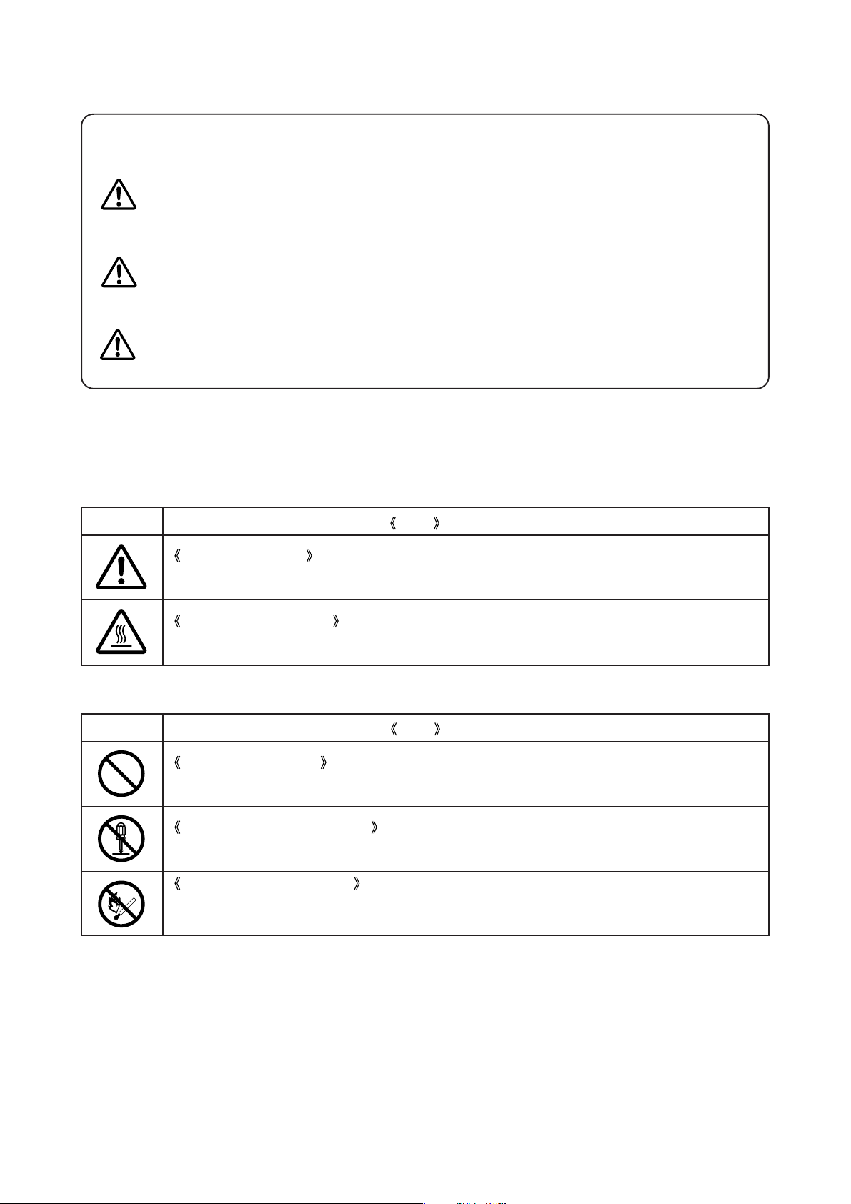
Three levels of warning indication are used throughout this Manual and on the unit. They are defined as
follows.
A DANGER notice indicates an immediately hazardous situation which, if not
DANGER:
WARNING:
CAUTION:
avoided, will result in death or serious injury, serious damage to property such as
total loss of use of equipment, and a fire.
A WARNING notice indicates an indirectly (potentially) hazardous situation
which, if not avoided, will result in death or serious injury, serious damage to
property such as total loss of use of equipment, and a fire.
A CAUTION notice indicates a hazardous situation which, if not avoided, can result in minor or moderate injury, partial damage to property, and loss of
data stored in computers.
[3] Definition of Marks
1. Marks to indicate caution or warning
Mark
General attention
Indicates unspecified general caution or warning.
Caution: Hot surface
Indicates that the surface can be dangerously hot.
2. Marks to prohibit action
Mark
General prohibition
Indicates unspecified general prohibition.
Prohibition of disassembly
Indicates prohibition of disassembly of the unit where it may cause an electric shock or other hazards.
Prohibition of use of fire
Indicates prohibition of use of fire where an external use of fire may cause the unit to ignite
under certain conditions.
Title and Indication
Title and Indication
−2−
Page 5
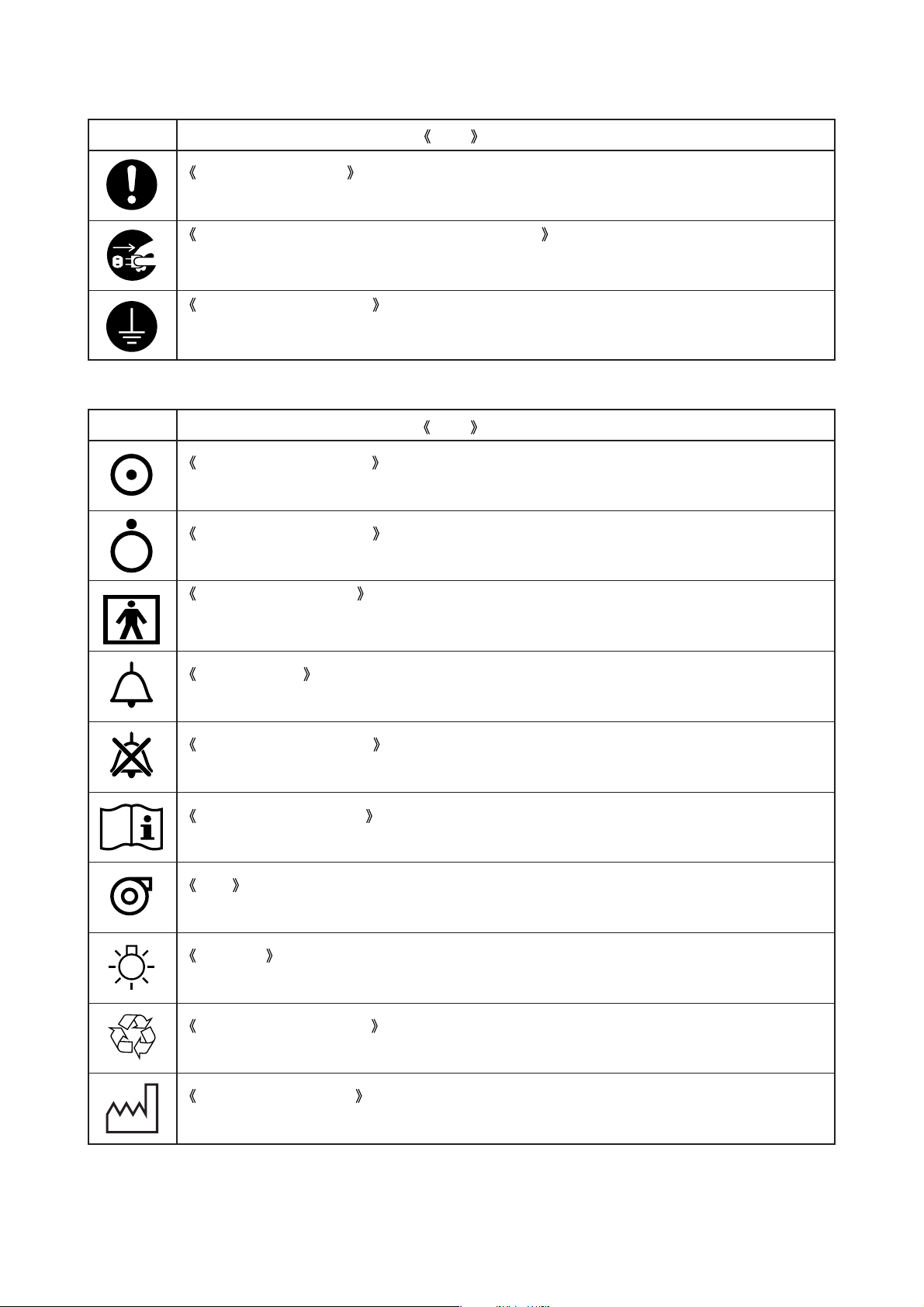
3. Symbols to give instructions for action
Mark
General instruction
Indicates unspecified general action on the part of the user.
Remove the power plug from the power outlet
Instructs the user to remove the power plug from the power outlet in the case of malfunction or
where lighting may occur.
Connect a ground wire
Instructs the user to connect the ground wire without fail where the unit is provided with a
ground terminal.
4. Symbols of international standards (IEC)
Mark
Equipment partially on
Indicates that a part of the device is “ON”.
Equipment partially off
Indicates that a part of the device is “OFF”.
Title and Indication
Title and Indication
Type BF applied part
Indicates that the device is classified as Type BF in terms of the degree of protection against an
electric shock.
Alarm setting
Indicates a switch for setting the alarm function.
Audible alarm silenced
Indicates that an audible alarm is silenced.
See operation manual
Follow operation manual.
Fan
Indicates a control switch that controls the fan.
Lighting
Indicates a switch that controls lighting.
Recycle mark (battery)
Indicates that recycling is recommended.
Date of manufacture
Indicates the date when the unit was manufactured in the factory.
−3−
Page 6
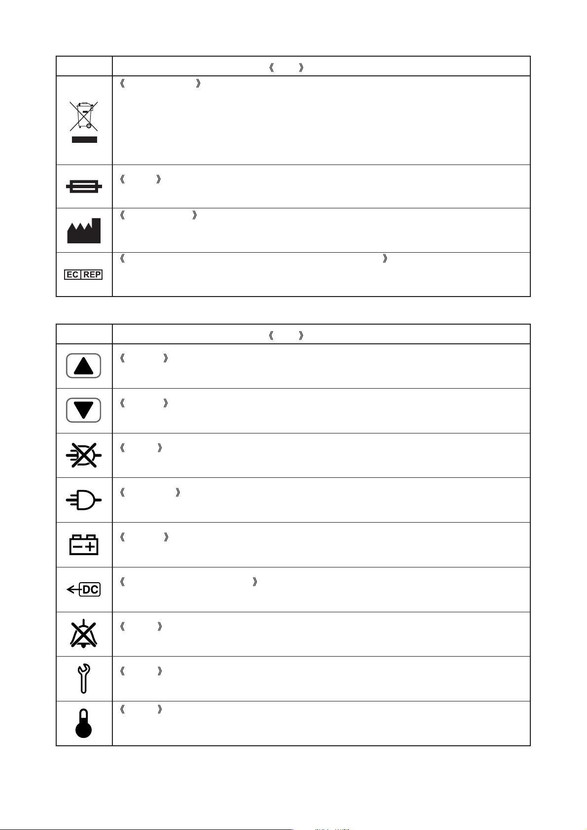
Mark
In the EC area, an electrical and electronic product falling in one of the categories specified by
“DIRECTIVE 2002/96/EC OF THE EUROPEAN PARLIAMENT AND OF THE COUNCIL of 27
January 2003 on Waste Electrical and Electronic Equipment (WEEE)” should be disposed of in a
manner consistent with relevant laws and regulations.
This symbol indicates that the above-mentioned requirement applies to this product.
Indicates the fuse.
This symbol indicates the name and the address shown adjacent to the symbol is of the manufacturer.
This symbol indicates the name and the address shown adjacent to the symbol is of the authorised
representative in the European Community.
5. Other symbols
Title and Indication
WEEE symbol
FUSE
Manufacturer
Authorised representative in the european community
Mark
Title and Indication
Setting
Indicates that a setting is increased.
Setting
Indicates that a setting is decreased.
Alarm
Indicates a power failure alarm.
AC power
Indicates that the device is connected to AC power.
Battery
Indicates that the device is being powered by a battery or batteries.
External DC power source
Indicates that the unit is operating on an external DC power source.
Alarm
Indicates that an audible alarm is silenced.
Alarm
Indicates that a system of the unit is in an abnormal condition.
Alarm
Indicates that the incubator air temperature has exceeded or fallen below the set temperature by
3˚C or more.
−4−
Page 7
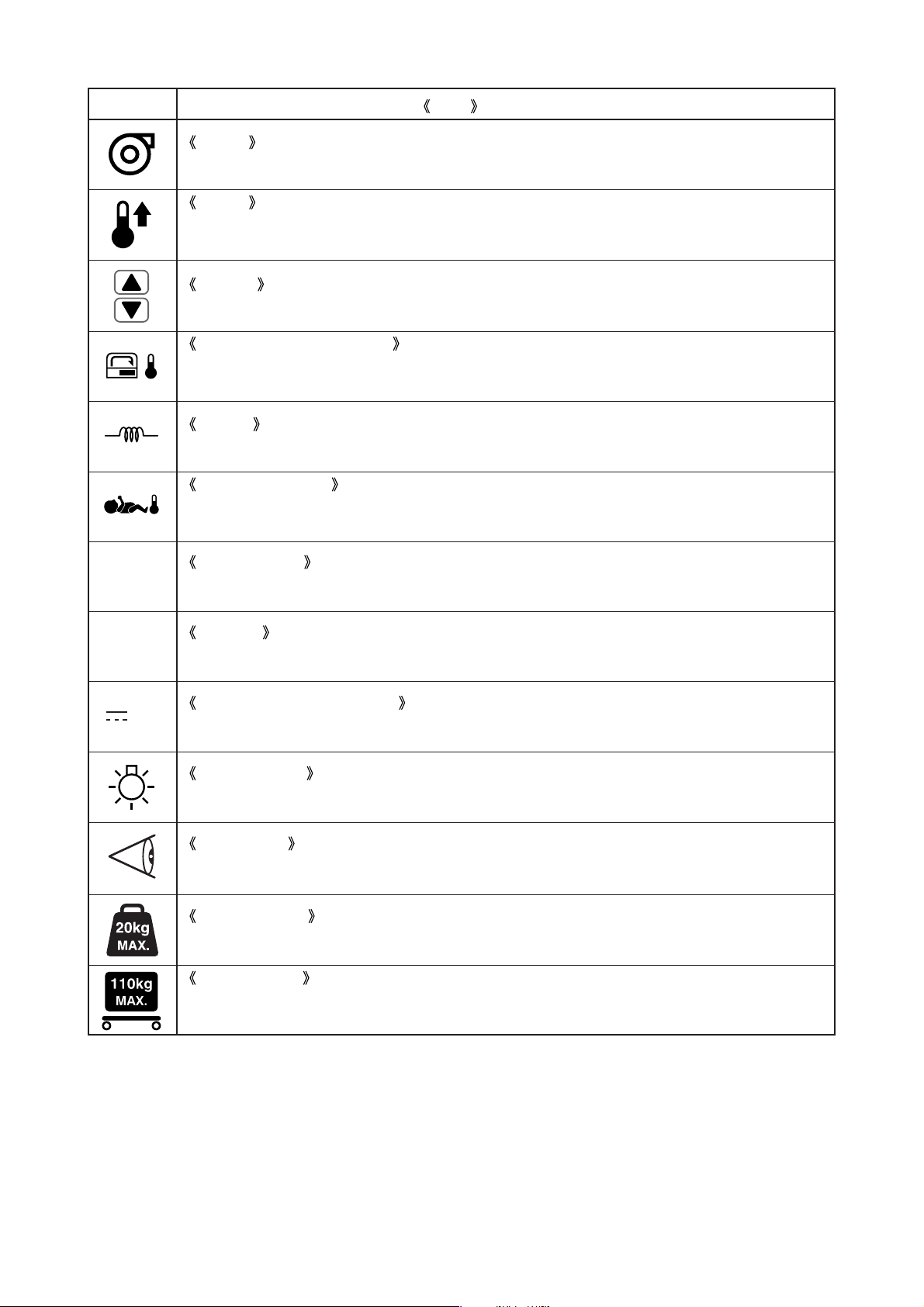
Mark
Title and Indication
Alarm
Indicates that the rotation of the fan is abnormal or the fan has not been attached.
Alarm
Indicates a high temperature condition with the incubator air temperature exceeding 39˚C, and
the high temperature adjusting volume.
Setting
Indicates a setting value of the incubator air temperature.
Incubator air temperature
Indicates a present incubator air temperature and the connecting port of the incubator air temperature sensor cable.
Heater
Indicates a heater output.
Skin temperature
Indicates the infant’s skin temperature, the connecting port of the skin temperature probe and
the connecting port of the skin temperature monitor cable.
POWER
BREAKER
12V
Power switch
Indicates the power switch of the main body.
Breaker
Indicates the breaker of the main body.
DC power connecting port
Indicates the DC power connecting port of the main body.
Lighting lamp
Indicates the lighting lamp cable connecting port.
Test switch
Indicates the test switch.
Load capacity
Indicates the maximum load capacity.
Gross weight
Indicates that the gross weight when peripheral devices of maximum loading capacity are attached to the product is as inscripted.
−5−
Page 8

Page 9
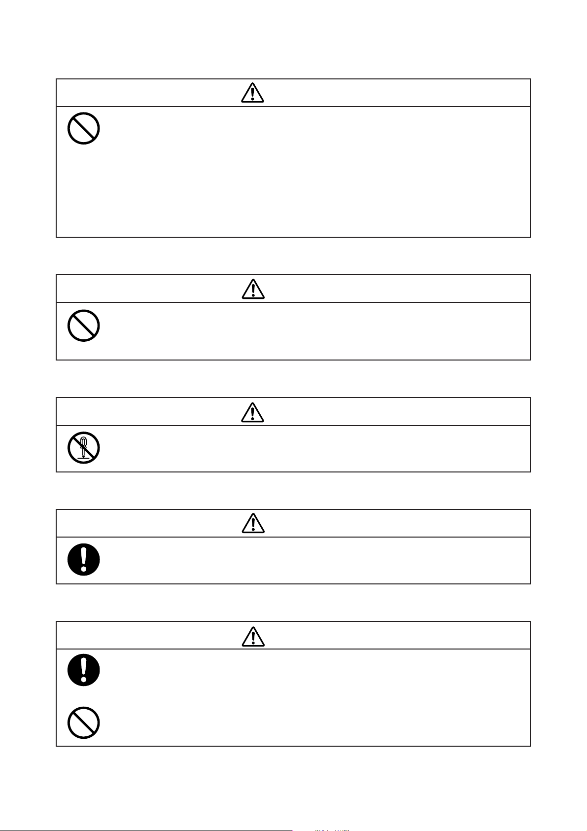
[1] Precautions on Jamming
WARNING
Electric surgical knives, portable and mobile communication equipment, and other devices which
generate high-frequency noise can cause jamming to various electric equipment for medical use
and thus result in malfunction.
Since portable and mobile communication equipment, etc. are often used in medical facilities,
some measures should be taken to prevent jamming due to such devices.
Portable and mobile communication equipment and other devices which generate high frequency
should not be used near the unit during its operation to prevent malfunction of the unit due to
jamming.
[2] Responsibility for Care of Equipment
CAUTION
It is the user (a hospital, a doctor’s office, a clinic) that is responsible for the operation, maintenance and care of the electric equipment for medical use. The equipment should be used only by
medical personnel.
[3] Prohibition of Modification
Do not disassemble or modify the unit. Otherwise a fire, an electric shock or injury may result.
[4] Periodical Inspection
Proper periodical inspection is needed to use the unit under optimum conditions.
[5] In Case of Trouble
If any abnormal condition or trouble should occur to the unit, indicate on the unit that it is out of
order and contact immediately your local Atom representative or service engineer. See this Operation Manual for whom to make contact.
WARNING
CAUTION
CAUTION
If any abnormal condition or trouble should occur, do not use the unit until it has been repaired
completely by a service engineer so as to prevent possible danger.
−7−
Page 10

Page 11

CONTENTS
INTRODUCTION ............................................................................................. 1
[1] Operating Precautions
1-1. DANGER .......................................................................................... 10
1-2. WARNING ........................................................................................ 12
1-3. CAUTION ........................................................................................ 13
[2] Parts Identification ...................................................................................... 15
[3] Setting up the Incubator
3-1. Assembling ............................................................................................. 21
3-2. Locking the Casters ............................................................................... 23
3-3. Adjusting the Height of the HL Stand ................................................. 23
3-4. Connecting the Power Pack to the Main Body .................................. 24
3-5. Where to Place the Incubator. .............................................................. 24
3-6. Fixing the Incubator to transport vehicle ........................................... 24
3-7. Power Outlet and Grounding ............................................................... 25
3-8. Power Cord and Power Switch ............................................................. 26
3-9. Inspection before Use ........................................................................... 27
[4] Power Source
4-1. Using the AC Power (AC220-240V) ..................................................... 28
4-2. Using the Battery Power ...................................................................... 29
4-3. Using the External DC Power (DC12V) ............................................. 30
[5] Incubator Air Temperature Control and Placing the Infant in the Incubator
5-1. Setting the Incubator Air Temperature ............................................... 31
5-2. Placing the Infant in the Incubator ...................................................... 33
5-3. Skin Temperature Monitoring ............................................................. 35
[6] Oxygen Supply ............................................................................................. 37
[7] Other Operating Procedures
7-1. Inserting the Cords and Tubes ............................................................ 39
7-2. Lighting Lamp ........................................................................................ 39
7-3. I.V. Pole (Option) ................................................................................... 39
7-4. Test Switch ............................................................................................. 40
7-5. Check Switch ......................................................................................... 40
7-6. Unlocking the Hood Lock (for opening the rear hood) .................... 40
[8] Cleaning and Disinfection
8-1. Skin Temperature Probe ....................................................................... 41
8-2. Hood ........................................................................................................ 42
8-3. Mattress Platform .................................................................................. 43
8-4. Replacing the Filter ............................................................................... 44
[9] Maintenance Inspection
9-1. Daily Inspection ..................................................................................... 45
9-2. Three-month Inspection ....................................................................... 46
9-3. Periodical Replacement Parts .............................................................. 46
9-4. Inspection Checklist .............................................................................. 47
9-5. Disposal .................................................................................................. 48
[10] Alarms and Alerts ........................................................................................ 49
[11] Troubleshooting ........................................................................................... 51
[12] Technical Data .............................................................................................. 52
[13] EMC level and Classification .................................................................... 54
[14] Accessories, Supplementary Equipment, Used Material .................. 58
Page 12

[1] Operating Precautions
Please follow the operating instructions described in this Manual for the safe use of the unit. The unit should
be operated only by those who have been trained and instructed properly in its operation. The unit should be
operated only for its intended use.
1-1. DANGER
Death or serious injury, damage to equipment or a fire will result if the instructions given below are not followed.
Be sure to keep the front admittance panel and the access ports closed
when using the unit.
If the front admittance panel or an access port is left open when the unit is in use, the infant may fall
out of the baby compartment. Be sure to keep the front admittance panel and the access ports closed
during phototherapy also when it is performed on an infant placed in the incubator.
Do not leave the unit unattended when the front admittance panel or an
access port is open.
If the front admittance panel or an access port is left open, the infant may fall out of the baby compartment and even lose its life. Never leave the unit unattended when the front admittance panel or an
access port is open.
If the front admittance panel, a snap-open access port or a hook slider should
be found loose or faulty, stop using the unit immediately and ask for repair.
The infant may fall.
Always check the front admittance panel operating retainer and the hook
sliders of the snap-open access ports for proper operation. If the front admittance panel or a snap-open port should not close securely, don’t place
an infant in the unit, and ask for repair.
Do not open the front admittance panel or an access port in order to lower
the incubator air temperature.
Because the incubator air temperature is controlled automatically at a set temperature, the heater
output will increase dangerously to make up for any temperature drop.
Open and close the snap-open access ports gently.
If you open or close them roughly, they may not open or close properly, which is dangerous.
After the infant is placed in the incubator, check again that the front admittance panel and the access ports are all closed securely.
Do not fasten the infant fixing bands too tightly.
If they are fastened too tightly, they will press the infant dangerously.
Never place a body warmer or other possible ignition sources in or near the
unit.
Use of oxygen will increase a risk of explosion or a fire. A body warmer or other devices in which fire
is used or which will generate a spark may cause an explosion or a fire if used near the unit.
−10−
Page 13

Do not use the unit in the presence of a flammable anesthetic gas.
The unit may cause an explosion or a fire if used in the presence of such a gas.
Do not use ether, alcohol or other ignitable substances.
Even a small amount of ether, alcohol or other ignitable substances may cause a fire when mixed
with the oxygen in the incubator.
If water or any liquid should get into the unit, stop using the unit and request a repair service.
If the power supply should be short-circuited, it may cause the incubator to ignite or burn out. Chemical
fluids, having entered the unit, may stick to the incubator parts and cause abnormal operation of the
incubator.
Ground the unit securely.
Otherwise, a leakage current may cause an electric shock. In order to complete the ground connection, connect the power cord only to a properly grounded 3P power outlet including a ground terminal. Do not operate the unit if you have any doubt about its ground connection.
Do not use a device generating high frequency near the unit.
To prevent malfunction of the unit due to jamming, do not use electric surgical knives, portable and
mobile communication equipment and other devices which generate high frequency near the unit
during its operation.
Analyze arterial gas levels repeatedly when a high oxygen environment is
required.
It is reported to be extremely important and essential, when the infant’s conditions call for a high
oxygen environment, to repeatedly analyze arterial gas levels in order to maintain the oxygen concentration in the incubator at a desired level. Follow the doctor’s instructions in measuring the oxygen concentration because ignoring essential requirements may increase a risk of retinopathy of
prematurity and other adverse effects.
Do not give a shock to the unit or allow it to be struck by other objects.
The screws or fixed parts may become loose.
−11−
Page 14

1-2. WARNING
Death or serious injury due to a fire or an electric shock will result if the instructions given below are not
followed.
Always maintain the incubator air temperature at a fixed level during the
standby.
Place the infant in the incubator only when the incubator air temperature
has stabilized.
Be sure to follow the doctor’s instructions in setting the incubator air temperature.
Be sure to follow the doctor’s instructions in setting the oxygen concentration in the incubator.
Be sure to use oxygen intended for medical use.
Be sure to bear in mind the following precautions during oxygen supply.
쎲 Do not place a body warmer, a flashlight, oils and fats, or flammable vaporizable matters in the
incubator.
쎲 Use pure cotton for the infant’s clothing, bed sheets, etc. Do not use any material that is easily
charged with static electricity.
쎲 Use pure cotton or fire-proof materials for the clothing of doctors, nurses and those ambulance
men who handle this unit.
Bear in mind the following precautions while using oxygen supply equipment.
쎲 If oil, grease or a grease-like substance should get in contact with pressurized oxygen, a violent
spontaneous ignition may occur. Do not let such substances stick to the oxygen pressure regulator, the oxygen cylinder valve, piping, connections and other parts of oxygen supply equipment.
쎲 On a high-pressure oxygen cylinder, use only a tested pressure reducing valve or pressure regu-
lating valve indicated specifically for oxygen supply. Do not use such a valve for any gas other than
air or oxygen. It is dangerous to use a valve to supply a gas other than air or oxygen first and then
to supply oxygen again.
Smoking is prohibited in the room where the unit is installed. Do not place
any possible ignition sources in the room.
Avoid damaging the power cord.
A damaged power cord may cause a fire or an electric shock.
쎲 Do not pinch the power cord between the unit and the wall, a shelf or the floor.
쎲 Do not place the power cord near a heating apparatus or heat it.
쎲 Do not put anything heavy on the power cord.
쎲 Always grasp the power plug with your hand to remove the power cord from the power outlet.
A damaged power cord should be replaced immediately with a new one.
Use only the power cord supplied with the unit.
Otherwise a fire or an electric shock may result.
−12−
Page 15

Before cleaning or disinfecting the unit, be sure to turn off the unit, remove
the power plug and make sure that the incubator air temperature and the
heater temperature have sufficiently fallen.
Do not touch the power plug with a wet hand.
Touching the power plug with a wet hand may cause an electric shock.
Do not disassemble or modify the unit.
Disassembling or modifying the unit may cause a fire, an electric shock or injury.
Do not install the unit where it will be exposed to excessive humidity, dust
or steam.
Installing the unit in such a place may cause a fire or an electric shock.
The power outlet should be located near the unit to prevent accidental contact with a trailing power cord. Use a separate power outlet for each unit.
Do not put many loads on one power outlet.
In order to complete the ground connection, connect the power cord only to
a properly grounded 3P power outlet including a ground terminal.
Do not operate the unit if you have any doubt about its ground connection.
Ground peripheral electric equipment securely.
Electrical ratings of this unit are as follows:
q AC220-240V; power consumption 220VA; frequency 50/60Hz; operating voltage range AC198-
264V
w DC12V; 10A; operating voltage range 11.0-14.0V
The unit should not be connected to any other power source.
The unit should be serviced only by qualified personnel.
Be sure to inspect the unit before starting a day’s work.
Operating the unit without inspecting it before starting a day’s work may let a defect pass unnoticed
and cause a serious accident.
1-3. CAUTION
Injury or damage to ambient objects may result if the instructions given below are not followed.
Be sure to clean and disinfect the unit before using it for the first time after
purchase.
The unit is shipped without being disinfected.
When inserting a cord or a tube into the unit, be careful not to let it wind
around or squeeze the infant inside.
−13−
Page 16

Do not twist or pull the cords by force.
If any defect should be found, ask an expert for repair without attempting to repair it yourself.
Remove the power plug from the power outlet before moving the unit to
another place or when the unit is not going to be used for a long time.
Moving the unit to another place with the power plug connected to the power outlet will damage the
power cord and may cause a fire or an electric shock.
Remove the power plug from the power outlet before cleaning or disinfecting the unit.
Cleaning or disinfecting the unit with the power plug connected to the power outlet may cause an
electric shock.
Place the unit on a stable surface.
Placing the unit on an unstable platform or a tilted surface will cause it to fall or drop and may hurt
someone. Check the strength of the place where the unit is to be placed or installed.
Install the unit out of reach of small children.
Do not install the unit in direct sunshine or near a heating apparatus.
Do not expose the unit to an extraordinarily high temperature or an excessive humidity.
Do not place anything heavy on the unit.
The unit uses rechargeable batteries (a lead-acid battery and a nickel metal
hydride battery). To dispose of the unit, remove the lead-acid battery and
the nickel metal hydride battery from the unit and send them to authorized
recycling facilities for recycling.
Check the operation of the peripheral devices.
If a device transmitting or receiving weak signals is installed near the unit, it may be affected by the
electromagnetic waves generated by the latter. Check the operation of peripheral devices for any
effect before using the unit in clinical settings. Stop using the unit immediately if any trouble is
detected.
When you transfer the incubator by holding the handles, make sure you do
so with the help of another person.
The power pack weighs about 13kg. Please use caution when handling it.
Be sure to cover the mattress with a mattress sheet.
Do not place any baby directly on the mattress.
Be sure to attach the semi-iris access port cover to the snap-open access
port packing.
If you open the snap-open access port without attaching the semi-iris access por t cover, the incubator
air temperature and oxygen concentration will drop.
−14−
Page 17
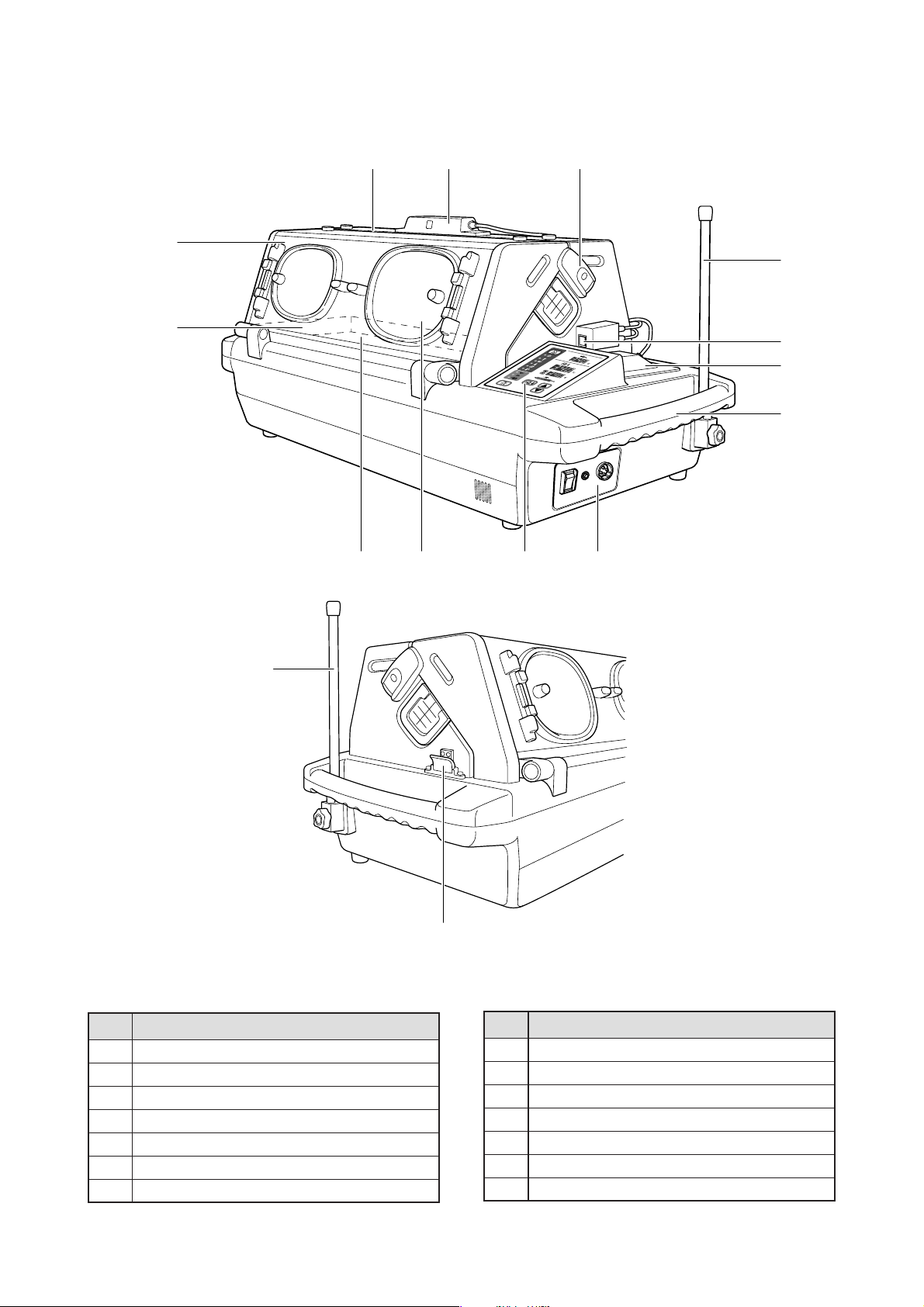
[2] Parts Identification
2-1. Main body
q
tre
y
w
y
u
i
o
!2!1!0
!3
!4
❉ The I.V pole (option) can be attached to either side of the incubator.
No.
q
Front admittance panel
w
Mattress platform (placed in the unit)
e
Front admittance panel packing
r
Lighting lamp
t
Front admittance panel retainer
y
I.V. pole (option)
u
Skin temperature probe connecting port
Name
−15−
No.
i
Oxygen supply port
o
Handle
!0
Mattress (placed in the unit)
!1
Snap-open access port
!2
Control panel
!3
Power panel
!4
Hood fixing device
Name
Page 18
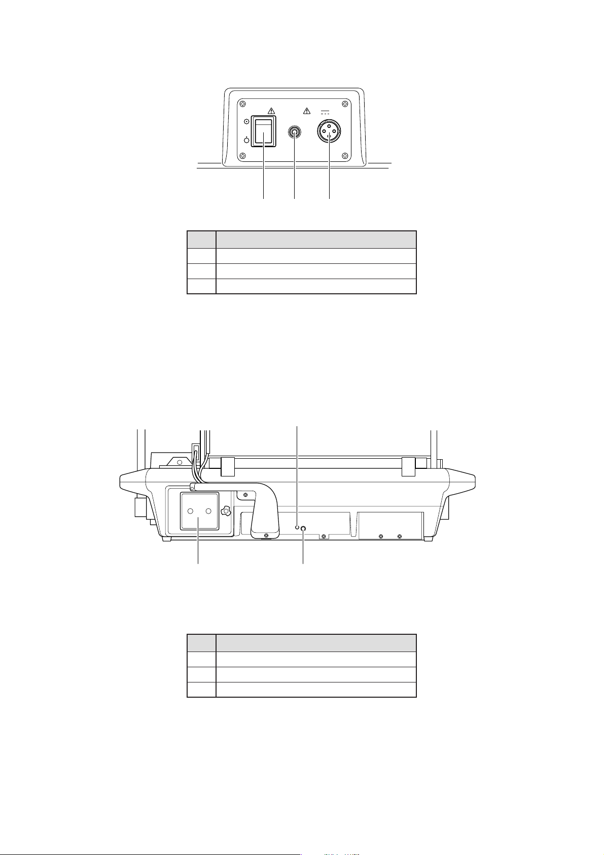
2-2. Right side of the main body (the power supply)
No.
q
Power switch
w
Breaker
e
DC power connecting port
2-3. Rear side of the main body
POWER BREAKER
15A
wq e
12V
Name
w
q e
No.
q
Filter
w
High temperature adjusting volume
e
Test switch
Name
−16−
Page 19
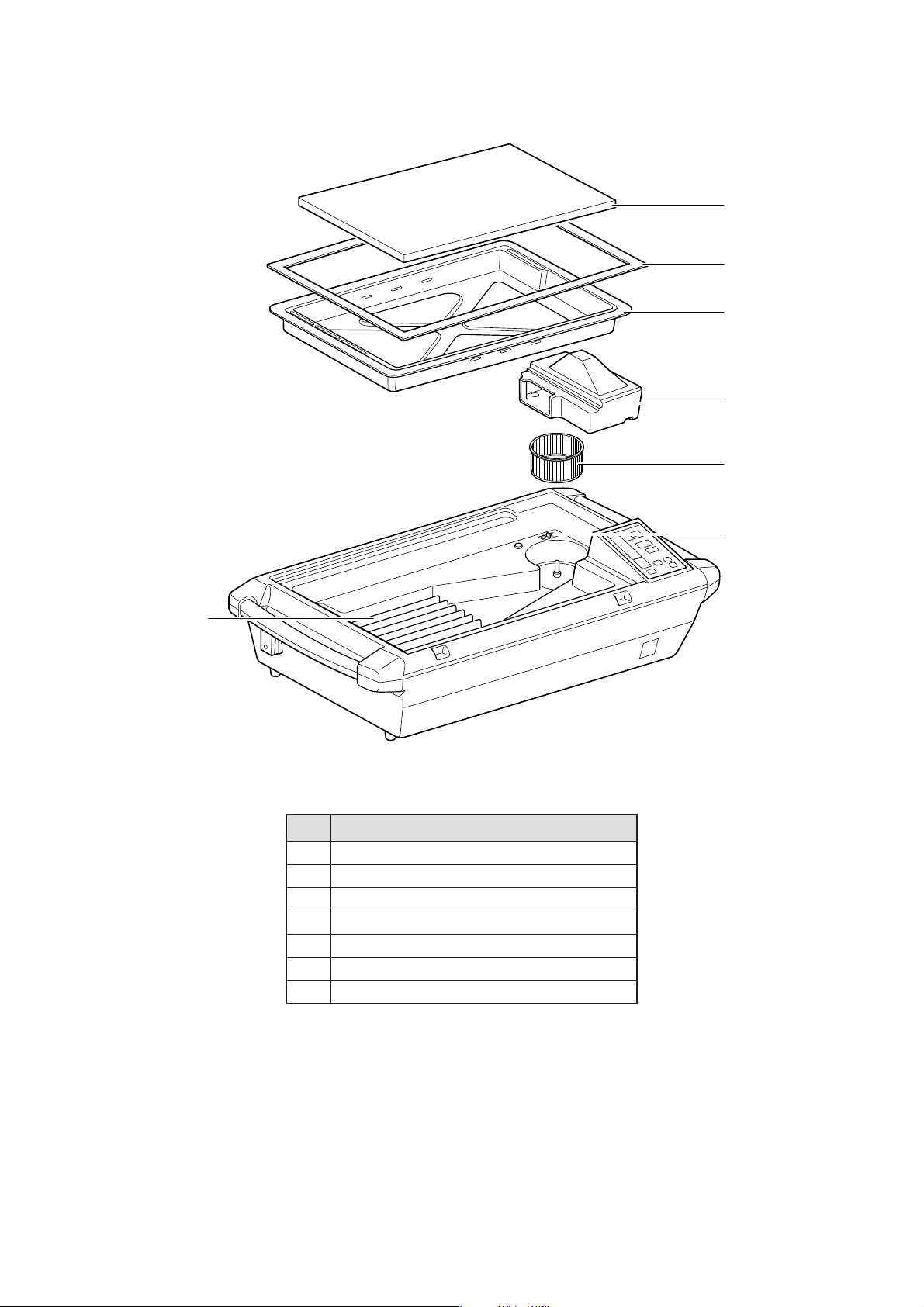
2-4. Inside of the main body
q
w
e
r
t
y
u
No.
q
Mattress
w
Hood packing
e
Mattress platform
r
Fan cover
t
Fan
y
Fan cover catch
u
Heater
Name
−17−
Page 20
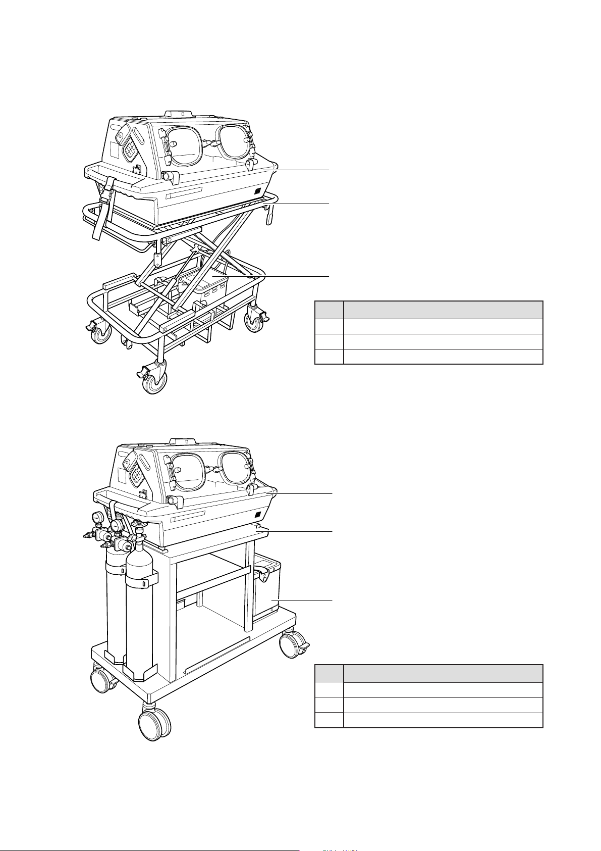
2-5. Stand
쎲 HL stand
q
w
e
쎲 Cabinet stand for internal hospital use
No.
q
Main body
w
HL stand
e
Power pack for V-707
q
w
e
Name
❉ The HL stand, Cabinet stand for internal hospital use and
Oxygen gas cylinder in the figure are not accessories.
−18−
No.
q
Main body
w
Cabinet stand for internal hospital use
e
Power pack for V-707
Name
Page 21
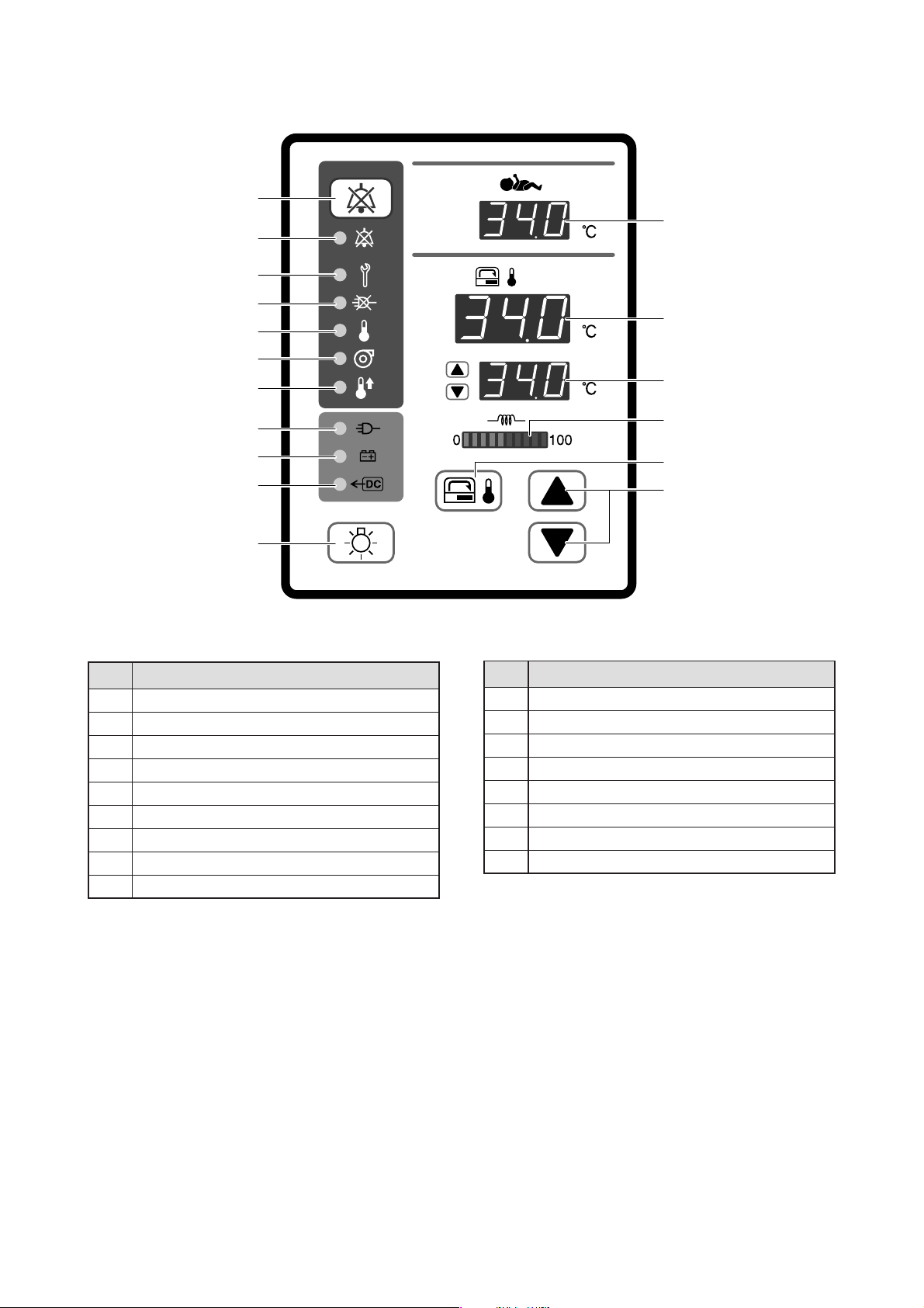
2-6. Operation panel
u
i
o
q
!0
!1
!2
!3
!4
!5
!6
!7
No.
q
Skin temperature display
w
Incubator air temperature display
e
Set temperature display
r
Heater output indicator
t
Incubator air temperature selector switch
y
Setting switch
u
Alarm silence/reset switch
i
Alarm silence indicator
o
System failure alarm indicator
Name
왓•왕
No.
!0
Power failure alarm indicator
!1
Set point alarm indicator
!2
Fan alarm indicator
!3
High temperature alarm indicator
!4
AC power indicator
!5
Battery power indicator
!6
External DC power indicator
!7
Lighting switch
Name
w
e
r
t
y
−19−
Page 22
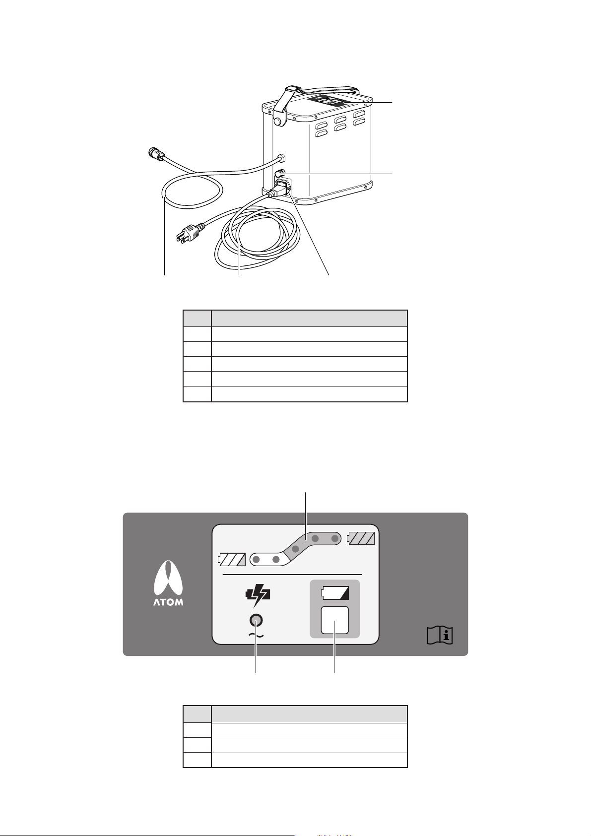
2-7. Power pack for V-707
q
w
re t
No.
q
Display panel
w
Fuse (for the battery)
e
Power pack cable
r
Power cord
t
AC inlet
2-8. Display panel (the power pack)
Name
q
w e
No.
q
Battery charge level indicator
w
Power (charging) indicator
e
Check switch
Name
−20−
Page 23
[3] Setting up the Incubator
3-1. Assembling
Assemble the separate components of the incubator correctly. If you use the HL stand or the Cabinet stand for
internal hospital use with the incubator, attach it correctly
to the incubator as instructed below.
CAUTION
The incubator is heavy. At least two able
people are required to assemble or move the
incubator.
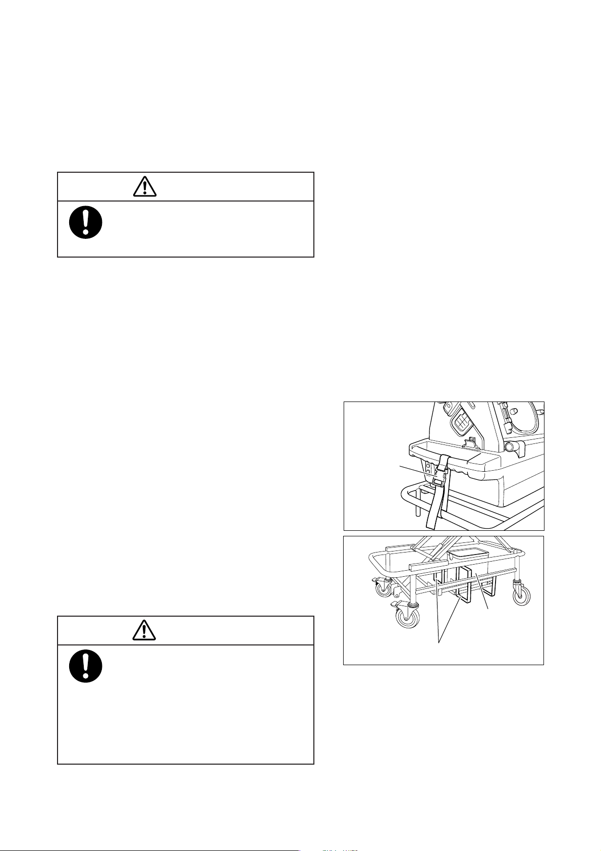
3-1-1. HL stand
(1) Place the incubator on the HL stand in such a way
that the front side of the incubator and the front side
of the HL stand will face in the same direction. At
this time, be sure to set the rubber feet attached to
the four corners of the incubator bottom securely
on the top surface of the stand so that the incubator
will not tilt or wobble.
(2) Put the main body fixing bands around the handle
of the incubator and the upper frame of the stand on
both sides of the incubator as illustrated and fasten
each fixing band securely.
(3) Place the power pack on the power pack holder at
the bottom of the stand. The stand is also equipped
with oxygen cylinder holders on the front side and
the rear side at the bottom. Two 500L cylinders can
be laid in the cylinder holders when needed.
WARNING
Be sure to put together the incubator and
the stand securely with the main body fixing
bands. Otherwise the incubator may tip over
when force is applied to open the hood, or it
may fall down when a shock is given during
transport. Never operate the incubator be-
fore it is fixed securely to the stand.
Main body
fixing band
Power pack
Cylinder holder
−21−
Page 24
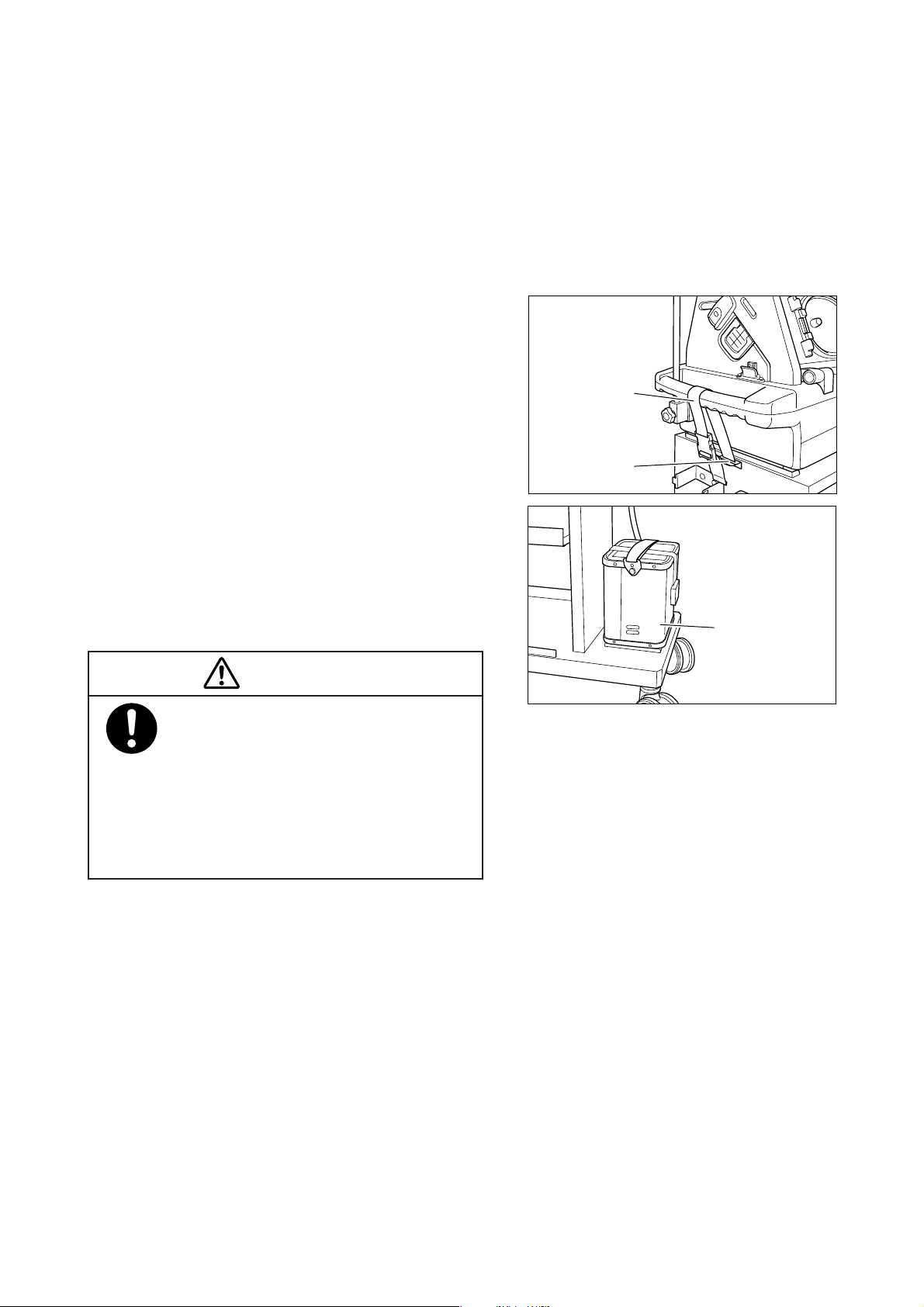
3-1-2. Cabinet stand for internal hospital use
(1) Place the incubator on the Cabinet stand for inter-
nal hospital use in such a way that the front side of
the incubator and the front side of the stand will face
in the same direction. In doing so, be sure to set the
rubber feet attached to the four corners of the incubator bottom securely on the top surface of the stand
so that the incubator will not tilt or wobble.
(2) Put the main body fixing band around the handle of
the incubator as illustrated and fasten the band securely by means of the fixing device on either side
of the stand.
(3) Place the power pack on the lower right surface of
the stand base and fix it securely in place with the
fixing band provided for the purpose. When needed,
two 500L cylinders can be laid on the lower left surface of the stand base. Fix the cylinders securely in
place with the fixing band provided for the purpose.
Main body
fixing band
Fixing device
Power pack
WARNING
Be sure to put together the incubator and
the stand securely with the main body fixing
bands. Otherwise the incubator may tip over
when force is applied to open the hood, or it
may fall down when a shock is given during
transport. Never operate the incubator be-
fore it is fixed securely to the stand.
−22−
Page 25
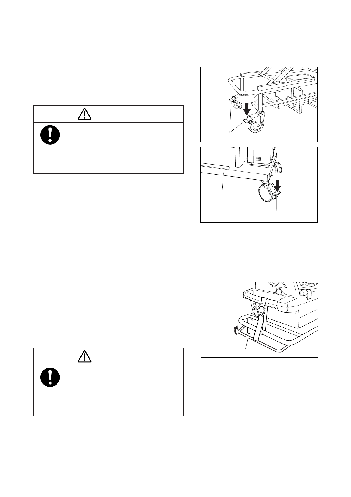
3-2. Locking the Casters
The casters of the HL stand and the cabinet stand for internal hospital use are provided with stoppers. To use
the incubator on the HL stand and the cabinet stand for internal hospital use, take the following steps.
(1) Install the incubator in a desired place and step on
the stoppers on the casters of the stand to lock them.
(2) To move the incubator to another place, unlock the
stoppers of the casters.
Lock
CAUTION
Install the HL stand and the cabinet stand for
internal hospital use on a horizontal and stable
place. Lock the stoppers on the casters to fix
the stand securely. To move the incubator to
another place, be sure to unlock the casters.
Stopper
Lock
Cabinet stand for
internal hospital use
Stopper
3-3. Adjusting the Height of the HL Stand
The height of the HL stand is adjustable freely within the range of 48~80cm. Take the following steps to adjust
the height.
(1) Check that the incubator is fixed securely to the
stand with the main body fixing bands.
(2) Hold the upper frame with both hands and pull up
the operating levers toward the upper frame. The
stand will be unlocked and can be moved up or down.
(3) Release the lever when a desired height is achieved,
and the stand will be locked at that height.
CAUTION
The stand is provided with a spring for elevation. Be sure to adjust the height of the stand
with the incubator fixed to the stand. For
safety’s sake, two people should cooperate in
adjusting the height.
Unlock the
stand
Operating lever
−23−
Page 26
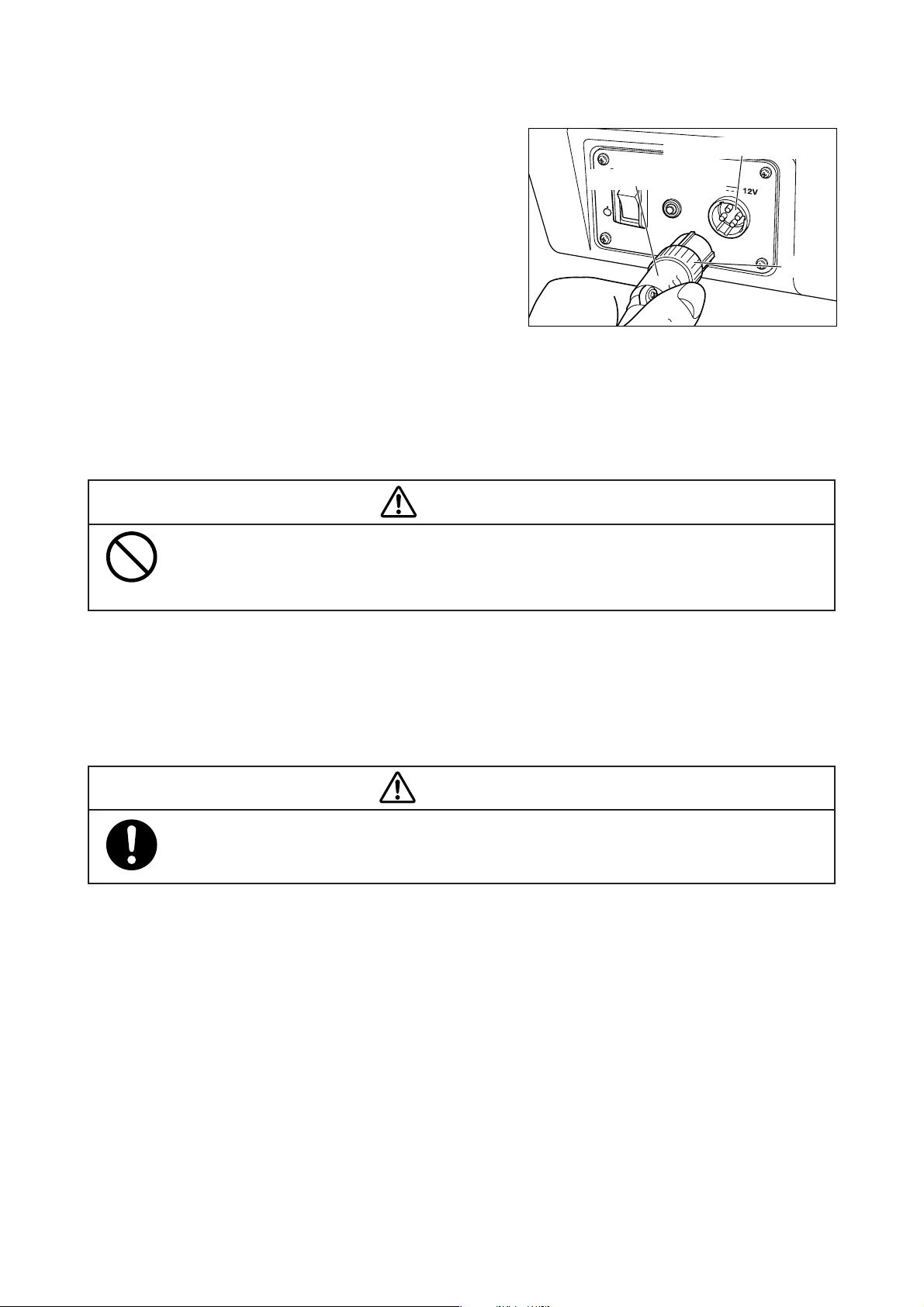
3-4. Connecting the Power Pack to the Main Body
쐽 Insert the connector of the power pack cable into the
DC power connecting port on the side of the main body
and turn the ring to attach the connecting cord securely.
Power pack cable
DC power connecting port
3-5. Where to Place the Incubator.
Except during transport, place the incubator on a horizontal sur face convenient for work. Avoid placing the
incubator near a heating apparatus, by the window or where fire is used.
CAUTION
Avoid placing the incubator in direct sunshine, near a stove or a radiator, in the direct airflow of an
air conditioner, or by a cold window. The incubator will be affected directly by these external thermal conditions.
Ring
3-6. Fixing the Incubator to transport vehicle
The method to fix the incubator to an ambulance varies with the type of ambulance. Consult the institutions
concerned (hospitals, the fire station) about the fixing method.
WARNING
Do not use the HL stand and the Cabinet stand for internal hospital use in an ambulance.
−24−
Page 27
3-7. Power Outlet and Grounding
The power outlet should be located near the unit to prevent accidental contact with a trailing
power cord. Use a separate power outlet for each unit.
Do not put many loads on one power outlet.
In order to complete the ground connection, connect the power cord only to a properly grounded
3P power outlet including a ground terminal.
Do not operate the unit if you have any doubt about its ground connection.
Ground peripheral electric equipment securely.
Electrical ratings of the unit for AC 220-240V and DC 12V power sources are as follows:
q AC220-240V: power consumption 220VA; frequency 50/60Hz; operating voltage range; AC198-
264V
w DC12V; 10A; operating voltage range; 11.0-14.0V
The unit should not be connected to any other power source.
WARNING
The unit should be serviced only by qualified personnel.
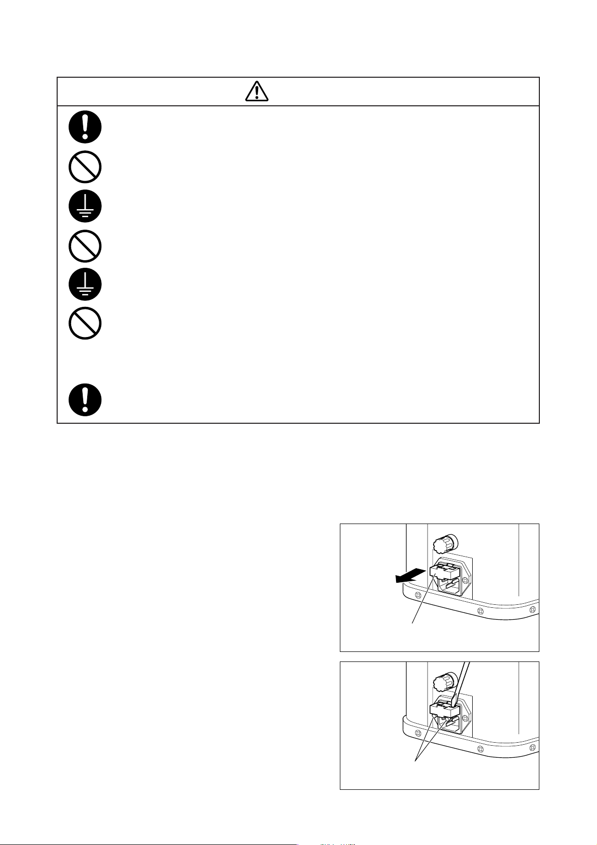
쐽 How to replace the fuse (at the AC inlet)
In order to prevent possible accidents due to an overcurrent, the fuse will burn out to shut off the AC power to
the unit. To replace the fuse, take the following steps:
(1) Turn of f the power switch.
(2) Remove the power cord from the AC inlet.
(3) Pull out the fuse box.
(4) Insert the tip of a screwdriver etc. into the hole on
the top of the fuse box and push to release the fuses.
(5) Replace any burnt fuses with new ones.
(6) Push the fuse box back into its former position.
(7) Connect the power cord to the AC inlet. If the re-
placed fuse should burn out again, contact your local Atom representative.
Fuse box
−25−
Fuse
Page 28
3-8. Power Cord and Power Switch
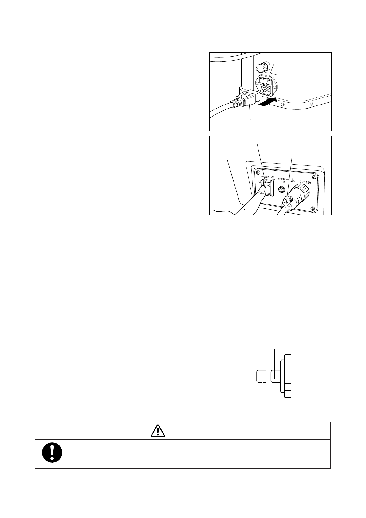
Tripped position
Normal position
(1) Connect the power cord to the AC inlet of the power
pack. Then connect the power plug on the other end
of the power cord to the power outlet.
Power cord
(2) Connect the power pack cable to the DC power con-
necting port on the power supply on the side of the
main body.
(3) Turn on the power switch.
쐽 Memory function
Information stored in the memor y will be retained by the memory function supported by the nickel metal
hydride battery in the main board.
If the power supply should be interrupted, the preselected settings will be retained in the memor y, so that it is
not necessary to set them anew when the power returns. When the power switch is turned on, the last selected
settings will be displayed.
Power switch
AC inlet
Power pack cable
쐽 How to reset the breaker ( for AC power and DC power)
If an overcurrent condition should occur during the operation of the unit, the breaker of the unit will be tripped
to shut off the power to the unit in order to prevent possible accidents. To reset the breaker, take the following
steps:
(1) Turn of f the power switch.
(2) Allow at least about one minute after the breaker
(3) Turn on the power switch.
was tripped, and then depress the breaker
pushbutton to reset it to the “Normal” position.
If the breaker should be tripped again, contact your
local Atom representative.
CAUTION
To prevent a malfunction, allow at least one minute or so after the activation of the breaker before
pressing the pushbutton.
−26−
Page 29
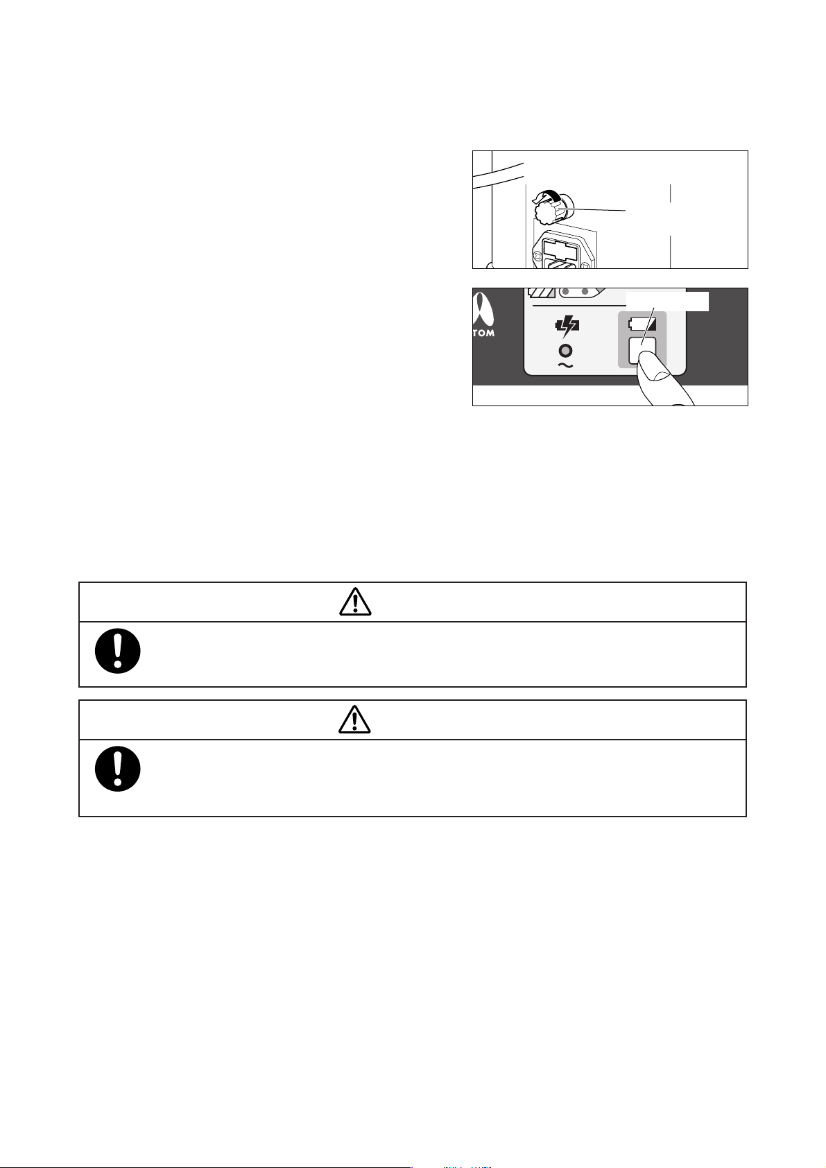
쐽 How to replace the fuse (for the battery)
If any faulty condition should occur to the circuit, the fuse will burn out to shut off the batter y power in order
to prevent possible accidents. To replace the fuse, take the following steps:
(1) Turn of f the power switch.
(2) Remove the power cord from the AC power source.
(3) Turn the fuse holder of the power pack counterclock-
wise while pressing it and remove the fuse holder.
(4) Replace the burnt fuse with a new one in the spare
fuse holder.
(5) After replacing the fuse, turn the fuse holder clock-
wise while pressing it and attach the fuse holder as
before.
(6) Press the check switch to check the battery charge
level (see “4-2. Using the Battery Power”).
(7) Connect the power cord to the AC inlet.
Tu rn the fuse holder while pressing it,
and the fuse holder can be removed.
Fuse holder for the
power pack
Check switch
3-9. Inspection before Use
Before using the unit, check it carefully for any trouble, contamination, missing parts or defective parts to
make sure that it can be operated safely.
WARNING
Be sure to inspect the unit before using it. Operating the unit without inspecting it before use may
let a defect pass unnoticed and cause a serious accident.
DANGER
Always check the front admittance panel retainers and the hook sliders of the snap-open access
ports for proper operation. If the front admittance panel or a snap-open access port should not
close securely, don’t place an infant in the unit, and ask for repair.
−27−
Page 30
[4] Power Source
This incubator is powered by the AC power source (AC220-240V), the battery (DC12V) or the external DC
power source (DC12V).
CAUTION
If the power cord is not connected to the power outlet or if the AC power source (AC220-240V) is
shut off, the unit will automatically switch to its battery power.
4-1. Using the AC Power (AC220-240V)
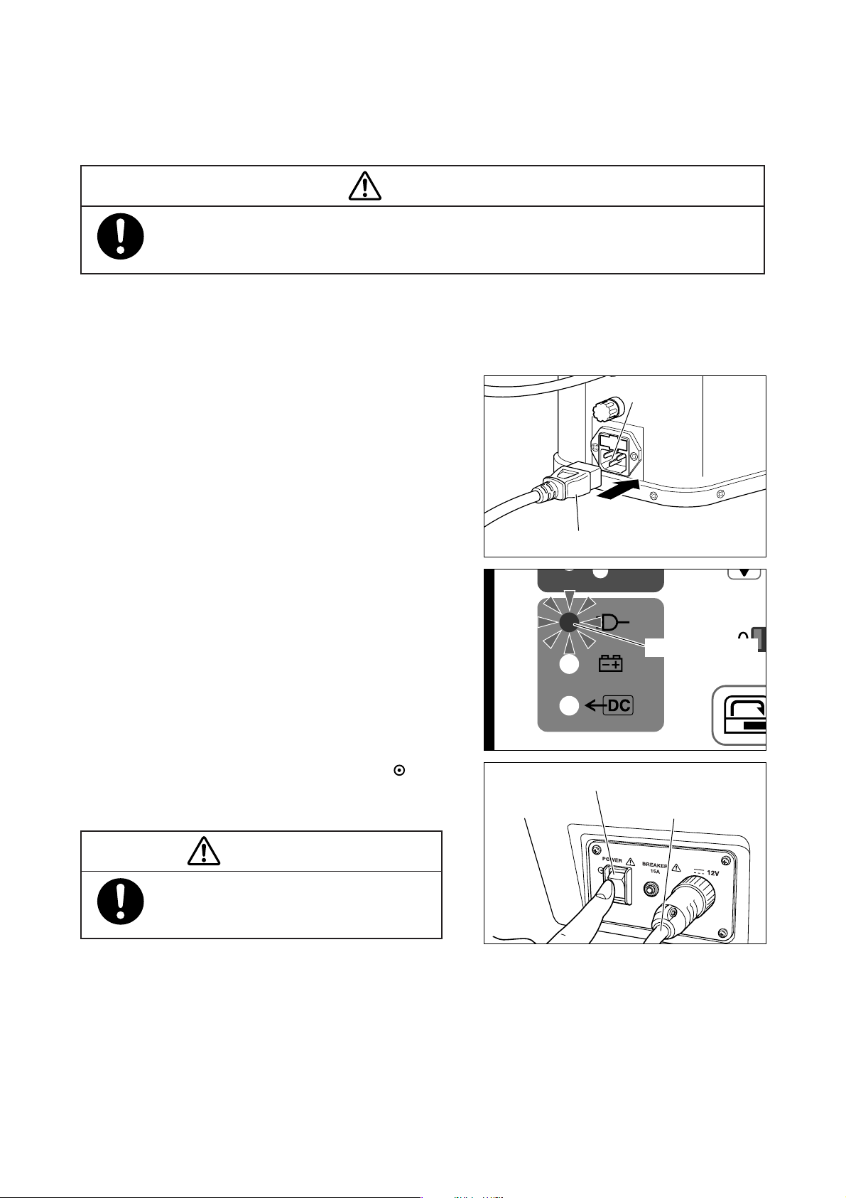
(1) Connect the power cord to the AC inlet of the power
pack.
Connect the power plug on the other end of the
power cord to the power outlet.
The power (charging) indicator of the power pack
will illuminate and the battery will be charged automatically.
(When the power pack cable from the power pack
is connected to the DC power connecting port of
the incubator, the AC power indicator on the operation panel will also illuminate whether the power
switch of the incubator is turned on or off.)
(2) Turn on the power switch of the incubator ( side).
The power will be supplied to the unit and the unit
will start operation.
AC inlet
Power cord
AC power indicator
Power switch
Power pack cable
CAUTION
At least five seconds must elapse before the
power is applied again.
−28−
Page 31
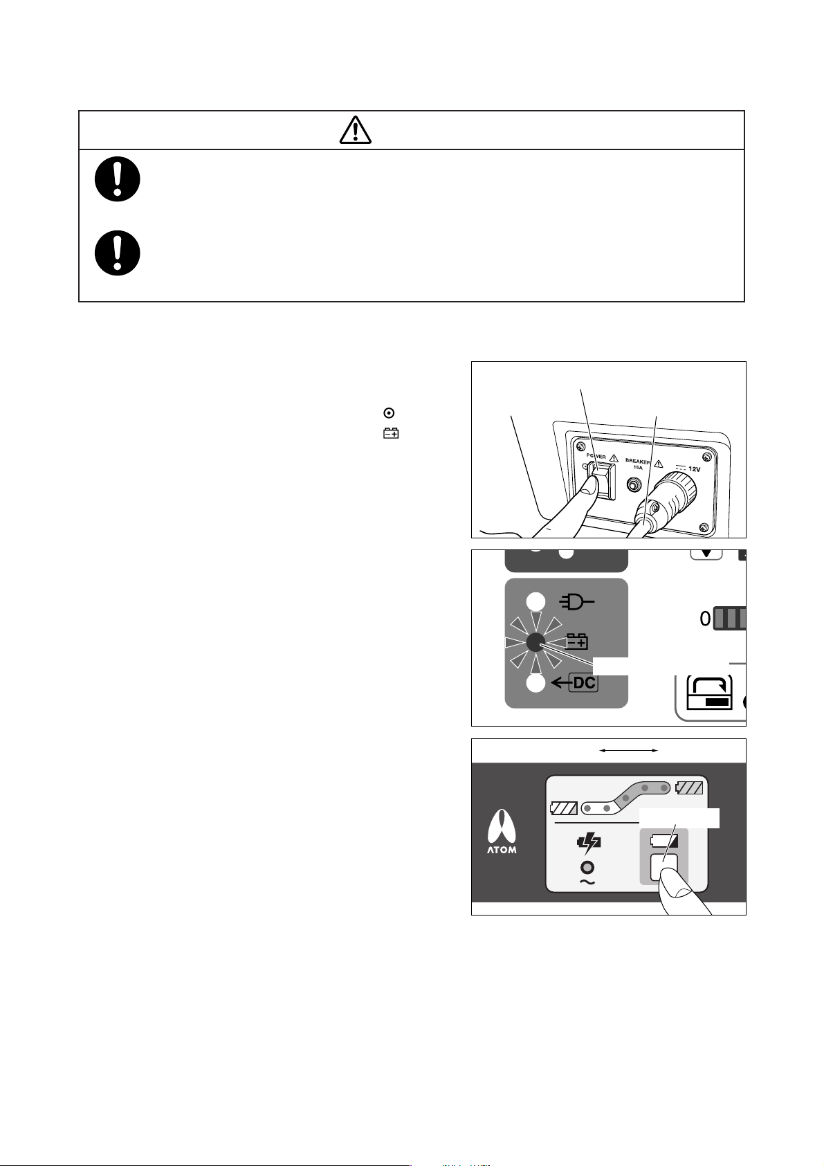
4-2. Using the Battery Power
CAUTION
The battery will wear out fast when it is used to power the incubator. Use the battery only when the
AC power source (AC220-240V) or the external DC power source (DC12V) cannot be used. Use
the AC power whenever possible.
The battery is a consumable part which will deteriorate over time whether it is used or not. The
battery life has come to an end when the operating time with the battery is noticeably short even
after the battery is fully charged. Ask for replacement immediately.
The battery charged for at least 20 hours (fully charged) enables approx. 90 minutes of continuous operation
[with the ambient air temperature at 15˚C and the incubator air temperature stable at 36˚C].
(1) Make sure that the unit is connected neither to the
AC power nor to the external DC power (DC12V).
(2) Turn on the power switch of the incubator ( side).
The battery power indicator adjacent to “ ” will
illuminate, the power will be supplied to the unit and
the unit will start operation.
(3) Press the check switch on the power pack to check
the battery charge level (voltage) of the power pack.
When all the five LEDs of the battery charge level
indicator are on, the battery is fully charged (after
being charged for approx. 20 hours).
The number of the illuminating LEDs decreases
from 5 씮 4 씮 3 씮 2 as the battery discharges.
When the only two LEDs in the white range are on,
recharge the battery as soon as possible.
Power switch
Power pack cable
Battery power indicator
Battery charge level 0 Fully charged
Check switch
−29−
Page 32
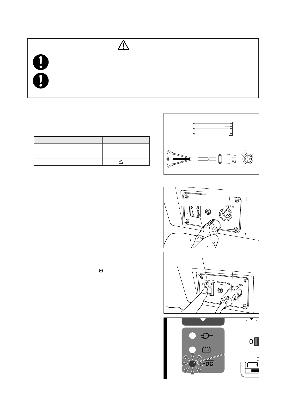
4-3. Using the External DC Power (DC12V)
CAUTION
Use only an external DC power source which meets the requirements of the international standers
IEC 60601-1 and IEC 60601-1-2 or which is equivalent in safety.
Only personnel familiar with electricity should connect the external DC power source. Make sure
that the external DC power source can supply the rated voltage and current and that it is provided
with a device to protect an overcurrent, such as a breaker.
쐽 Requirements for the external DC power source
Use only the external DC power source that meets the
requirements shown below. Otherwise the unit may not
operate.
DC12V
DC voltage range
Max. DC
Tr ansient voltage fluctuation
11.0 — 14.0V
10A
5%
쎵V (red)
앥V (black)
FG
(yellow/green)
Round terminal (ø6)
DC power cord
Connector
X
YNC
Z
G
X
G
Y
Z
쐽 Connecting the external DC power source
Connect the red round terminal of the DC power cord to
the side of the external power source and the black
round terminal of the DC power cord to the side. Connect the yellow/green round terminal to the frame ground
(FG). (The side is connected to the FG inside the main
body).
(1) Connect the DC power cord (option) to the DC
power connecting port on the right side of the main
body.
Turn the ring on the connector for secure connection.
(2) Turn on the power switch ( side). The external DC
power indicator will illuminate, the power will be supplied to the unit and the unit will start operation.
(3) To stop the operation on the external DC power, turn
off the power switch of the main body and remove
the DC power cord from the DC power connecting
port.
DC power connecting port
Power pack cable
Ring
Power switch
Power pack cable
(4) When the external DC power is not used, keep the
power pack connecting cord connected to the DC
power connecting port.
❉ Either the power pack connecting cord or the DC
power cord for the external DC power source can be
connected to the DC power connecting port on the
main body of the incubator.
−30−
External DC
power indicator
Page 33
[5]
Incubator Air Temperature Control and Placing the Infant in the Incubator
5-1. Setting the Incubator Air Temperature
Practice and master the operation procedure before placing the infant in the incubator. Conduct temperature
tests with the unit empty in order to make sure that it operates normally.
WARNING
Be sure to follow the doctor’s instructions in setting the incubator air temperature.
CAUTION
Practice and master the operation procedure before placing the infant in the incubator. Conduct
temperature tests with the unit empty in order to make sure that it operates normally.
While the infant is in the incubator, check the heater output, the incubator air temperature and the
oxygen concentration continuously to make sure that nothing is the matter with the infant.
Check that the air outlets are not blocked with a diaper, gauze or other materials. If they are blocked,
the temperature in the incubator cannot be controlled correctly.
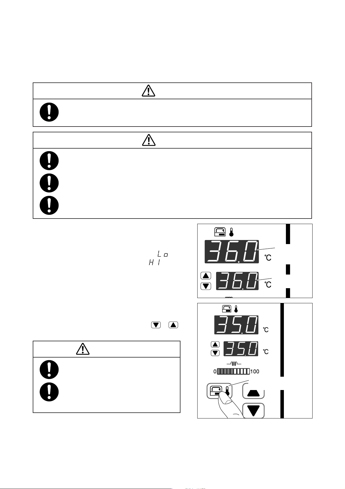
(1) Turn on the unit and check that the incubator air
temperature and the set temperature are displayed.
The incubator air temperature is displayed in the
range of 20.0-42.0˚C in 0.1˚C increments. “ ” will
be displayed if it is 19.9˚C or lower; “ ” will be
displayed if it is 42.1˚C or higher.
The set temperature can be selected in the range of
23.0-38.0˚C in 0.1˚C increments.
(2) To set or change the incubator air temperature, press
the incubator air temperature selector switch for
about 1 second. While the set temperature is flashing, press an appropriate setting switch ( or )
to set the incubator air temperature to a desired level.
WARNING
Be sure to follow the doctor’s instructions in
setting the incubator air temperature.
Please double check to make sure that the
incubator temperature setting is consistent
with your doctor’s instructions.
Incubator air
temperature
display
Set temperature
display
Incubator air temperature
selector switch
−31−
Page 34
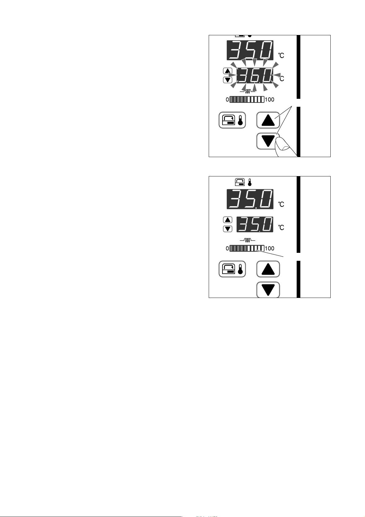
(3) Allow about 30-40 minutes for the incubator air tem-
perature to stabilize (depending on the ambient temperature).
The incubator air temperature is regarded as stabilized when it is equal or close to the set temperature.
쐽 Heater output indicator
The heater output indicator indicates the amount of heat
supply required to maintain the incubator air temperature at the preselected level. As the incubator air temperature rises toward the set temperature, the heat supply decreases and the output level shown on the heater
output indicator also decreases gradually from 100. When
the incubator air temperature has reached the set temperature, the reading on the indicator stays within the
balanced heat supply range. Thus the heater output indicator helps grasp the changes in incubator air temperature control.
Setting switch
Heater output
−32−
Page 35
5-2. Placing the Infant in the Incubator
WARNING
Place the infant in the incubator only after the incubator air temperature has stabilized.
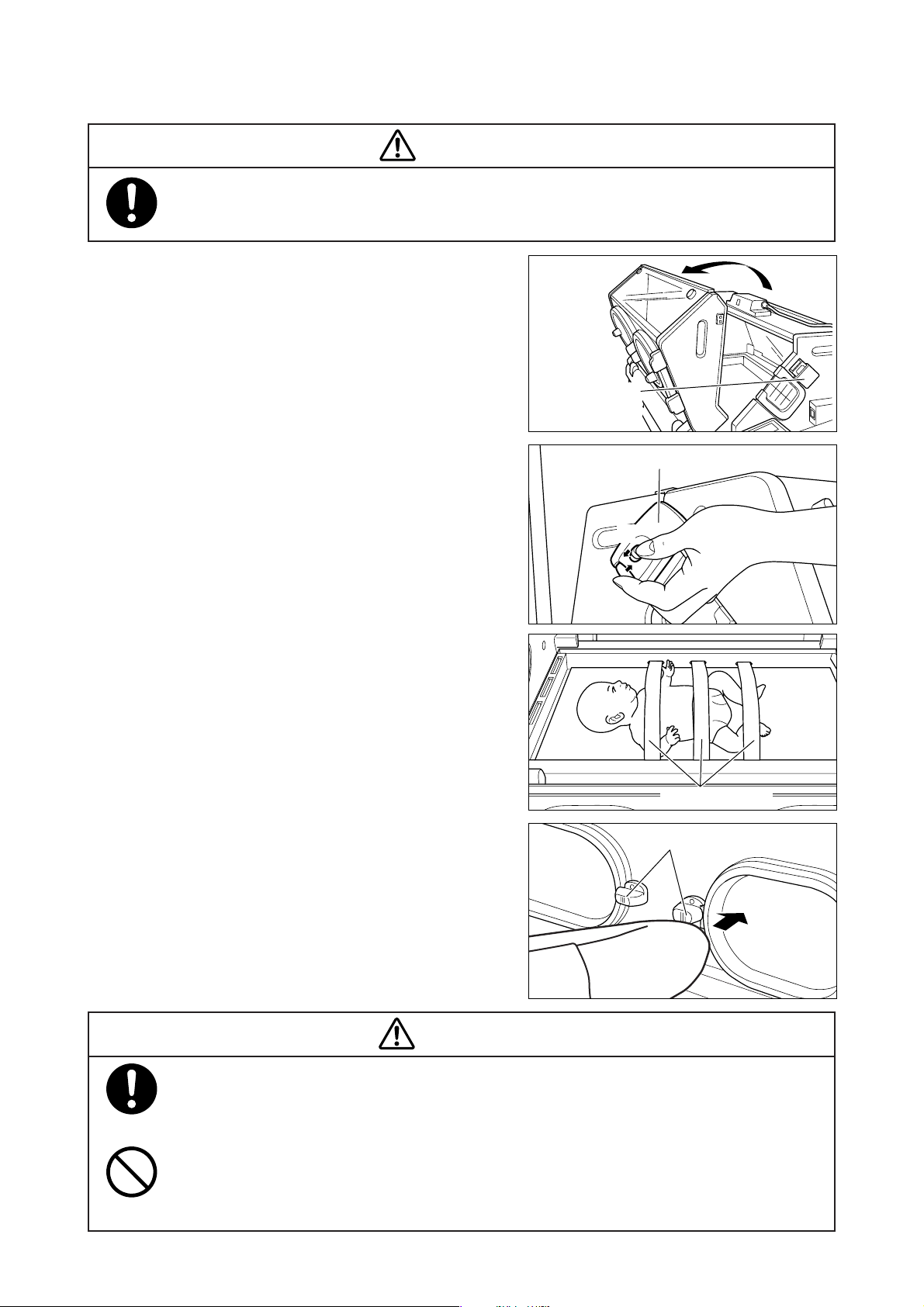
(1) Unlock the front admittance panel retainers on both
sides of the front admittance panel and fold down
the admittance panel gently toward you.
Front admittance
panel retainer
To unlock the retainers, hold the knob with your
fingers and push it in the directions of the arrows
q and w.
(2) Place the infant on the center of the mattress with
the head to the left and the legs to the right. Fix the
infant securely with the infant fixing bands attached
to the mattress platform.
(3) After placing the infant, close the front admittance
panel and lock the front admittance panel retainers
securely.
(4) A gentle touch by the elbow on a hook slider will
open a corresponding snap-open access por t. To
close the port, push the por t door until it closes completely.
Front admittance panel retainer
q
w
Infant fixing band
Hook slider
DANGER
Always check the front admittance panel retainers and the hook sliders of the snap-open access
ports for proper operation. If the front admittance panel or a snap-open access port should not
close securely, don’t place an infant in the unit, and ask for repair.
Do not open the front admittance panel or an access port in order to lower the incubator air
temperature. Since the incubator air temperature is controlled automatically at a set tempera-
ture, the heater output will increase dangerously to make up for any temperature drop.
−33−
Page 36
DANGER
Open and close the snap-open access ports gently. If you open or close them roughly, they may
not open or close properly, which is dangerous.
After the infant is placed in the incubator, check again that the front admittance panel and the
access ports are all closed securely.
For the infant’s safety, never leave the incubator unattended when the front admittance panel or
an access port is open.
Do not fasten the infant fixing bands too tightly. If they are fastened too tightly, they will press the
infant dangerously.
CAUTION
Place the infant in the incubator only after the incubator air temperature has stabilized.
Opening the front admittance panel or access ports, covering the infant with a sheet, or using an
oxygen headbox, etc. in the incubator will change the air circulation pattern inside the incubator.
This may affect the thermal uniformity, thermal changes, the detection and control of the incubator air temperature, and the infant’s skin temperature.
Avoid opening the entire hood to place the infant in the incubator. It will cause the incubator air
temperature to fluctuate greatly.
Never open the entire hood when the infant is in the incubator because the cords and tubes may
injure the infant. All procedures should be performed through the front admittance panel or the
access ports.
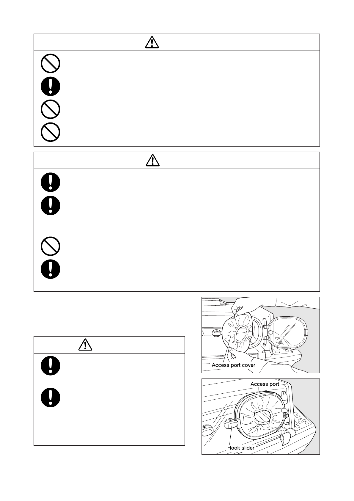
(5) Attach the semi-iris access port cover to the edge of
the snap-open access port on the hook slider side.
Then continue to attach the semi-iris access port
cover to the edge of the access port packing.
CAUTION
After attaching the semi-iris access port cover,
make sure that the hook slider is holding the
access port securely in place.
Be sure to attach the semi-iris access port
cover to the snap-open access port packing.
If you open the snap-open access port without attaching the semi-iris access port cover,
the incubator air temperature and oxygen
concentration will drop.
−34−
Page 37
5-3. Skin Temperature Monitoring
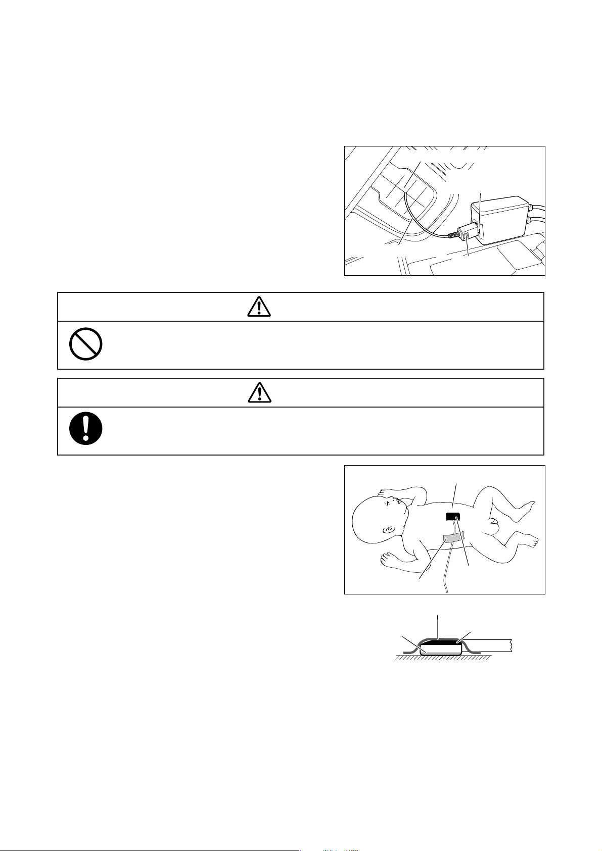
To monitor the skin temperature of the infant placed in the incubator, it is necessary to attach a skin temperature probe to the infant. The skin temperature probe is to be connected to the skin temperature probe connecting port on the right side of the main body. The temperature detected by the skin temperature probe will be
displayed on the skin temperature display.
(1) Insert the plug of the skin temperature probe firmly
in the skin temperature probe connecting port on
the right side of the main body.
(2) Pass the skin temperature probe cable through the
tube introduction slit packing on the side of the hood
into the incubator.
(3) Before attaching the skin temperature probe to the
infant, clean the site of attachment with alcohol or
lukewarm water to get rid of any fetal fat or dirt.
WARNING
Do not place the skin temperature probe under the infant. Do not use it as a rectal probe.
CAUTION
Follow the doctor’s instructions as to where to attach the skin temperature probe when the infant
is in a prone position.
Tube introduction slit packing
Skin temperature probe
connecting port
Skin temperature probe
(Plug)
(4) Place the yellow skin temperature probe between
the navel and the xiphoid process on the infant abdominal median line and attach it with the “Cover
Baby”. The heat-sensing surface should touch the
skin. Affix a piece of tape at a slight distance from
the tip of the probe and fix the probe securely to the
skin.
(5) The temperature detected by the skin temperature
probe will be displayed on the skin temperature display.
Tape
“Cover Baby”
Heat-sensing
surface
“Cover Baby”
Temperature probe
Resin
Metal
Skin
−35−
Page 38
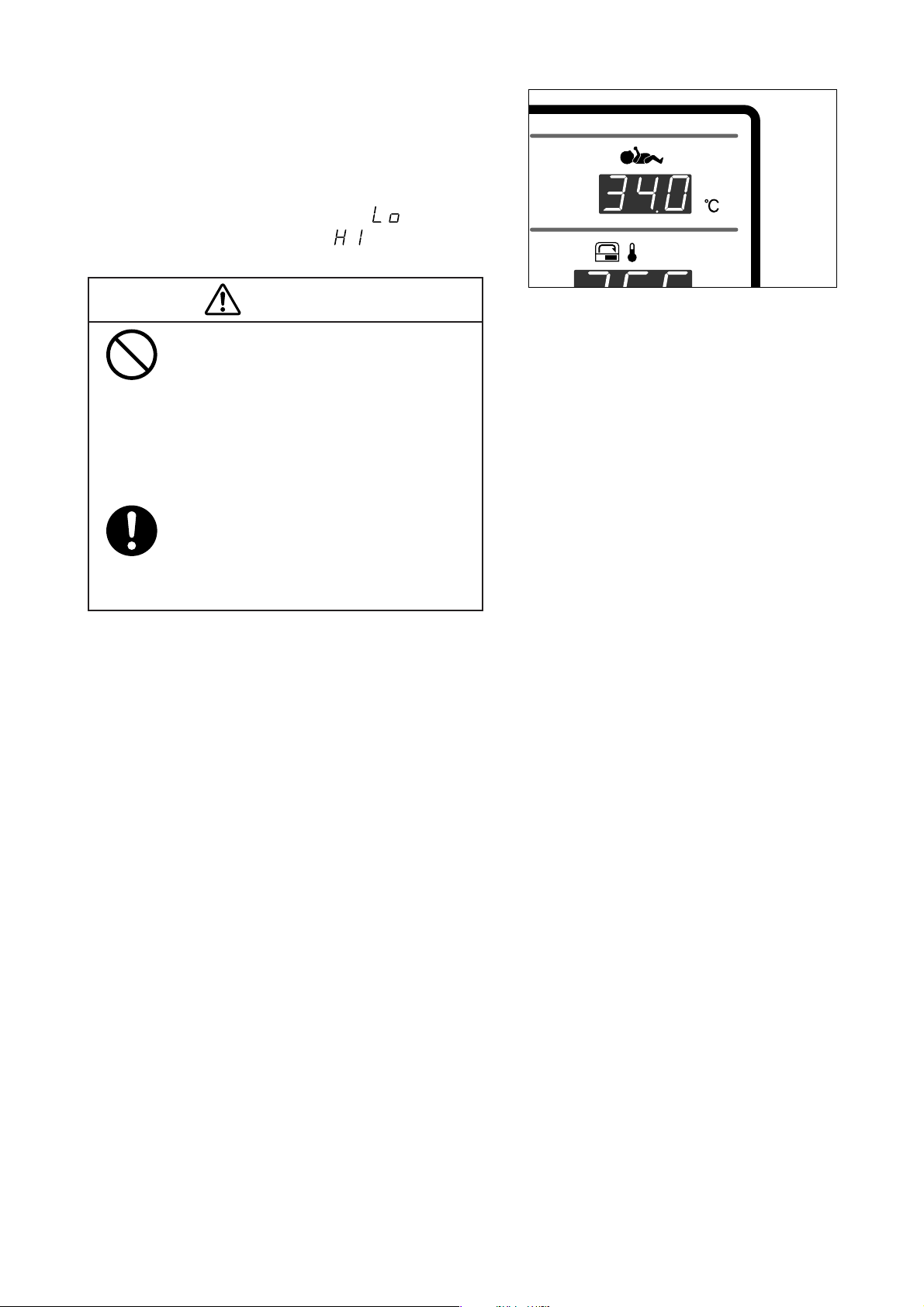
(6) Allow 4-5 minutes after connecting the skin tempera-
ture probe for the temperature reading to stabilize
and then start skin temperature monitoring with the
skin temperature probe.
The skin temperature is displayed in the range of
30.0-42.0˚C in 0.1˚C increments. “ ” will be displayed if it is below 30.0˚C; “ ” will be displayed
if it is above 42.0˚C.
CAUTION
If the heat-sensing surface of the skin temperature probe is attached improperly to the
infant, or if it should be dislodged accidentally from the infant, the skin temperature
cannot be detected accurately. Make sure that
the heat-sensing surface has been attached
properly to the infant.
Pay close attention to the infant during skin
temperature monitoring so that the infant will
not become entangled in the skin temperature probe.
−36−
Page 39
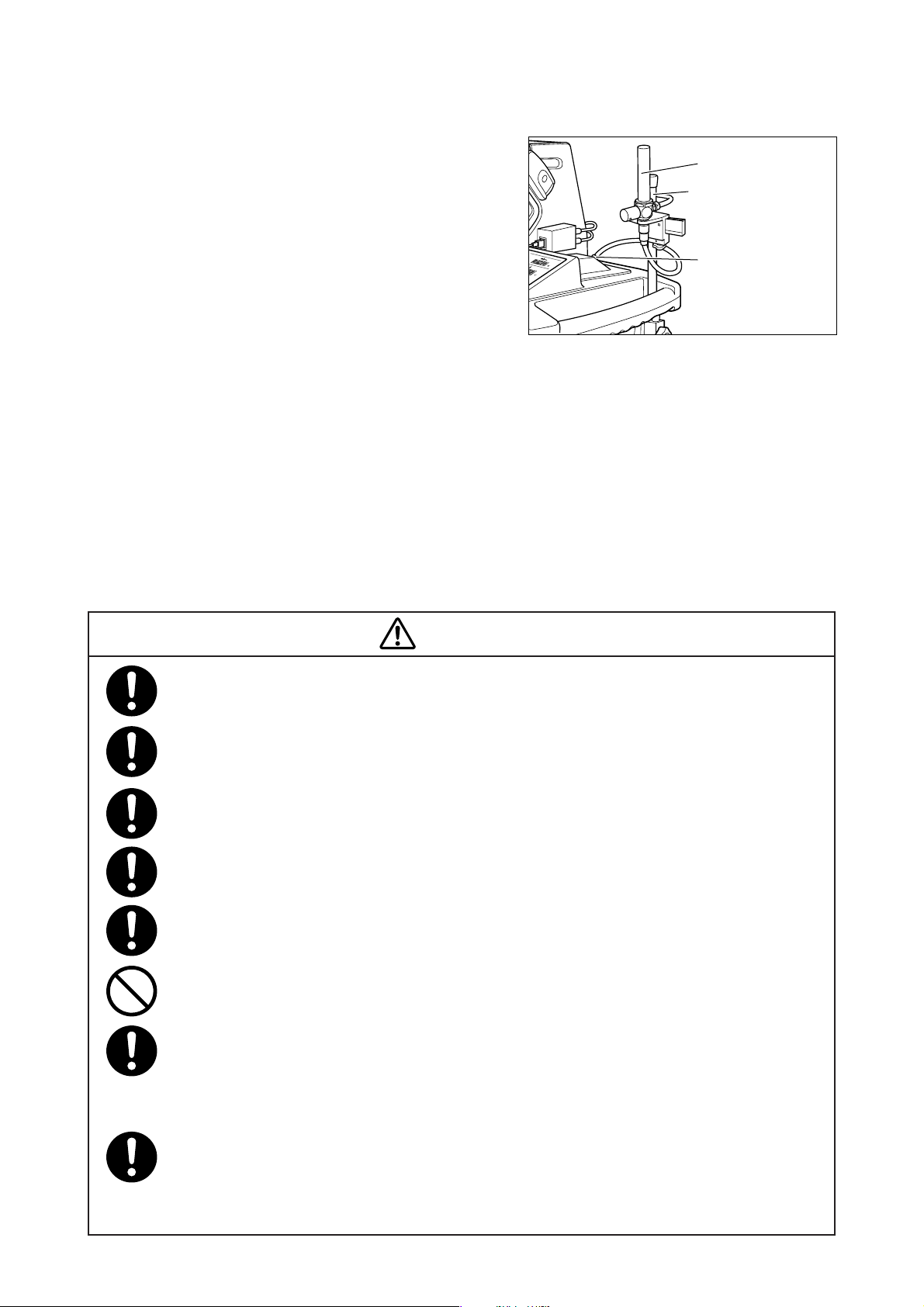
[6] Oxygen Supply
(1) Be sure to connect an oxygen flowmeter between
the oxygen supply source and the oxygen supply
port of the incubator. Turn the knob on the oxygen flowmeter and adjust the flow rate to a desired
level.
(2) The oxygen concentration in the incubator will
stabilize in about 30 minutes.
Increase the supply flow rate if the detected oxygen
concentration in the incubator is lower than the
desired level; decrease the supply flow rate if the
detected oxygen concentration in the incubator is
higher than the desired level.
Pay utmost attention to the changes in the oxygen
concentration in the incubator by monitoring it with
an oxygen monitor till it stabilizes.
쐽 Connecting the oxygen cylinder
To connect the oxygen cylinder, use the optional high pressure oxygen hose (for the V-505/pressure reducing
regulator) and the optional OX-231 pressure reducing regulator (for oxygen).
Oxygen flowmeter
I.V. pole (option)
Oxygen supply port
WARNING
Be sure to use an oxygen cylinder intended for medical use.
Be sure to connect an oxygen flowmeter between the oxygen supply source and the oxygen
supply port of the incubator.
Be sure to follow the doctor’s instructions in making decisions on oxygen supply.
Pay utmost attention to the oxygen concentration in the incubator during the oxygen supply.
Be sure to use oxygen intended for medical use.
Never supply humidified oxygen to the oxygen supply port. Supplying humidified oxygen by means
of a humidifying jar or other devices may damage the oxygen supply port of the incubator.
Pay utmost attention to the changes in the oxygen concentration in the incubator by monitoring
it continuously with an oxygen monitor. If the oxygen concentration in the incubator deviates
from a desired level, make necessary adjustments by increasing or decreasing the oxygen flow
rate.
Improper use of supplementary oxygen may cause serious side effects including loss of sight,
damage to the brain and death. The risk of side effects varies with infants. Follow the doctor's
instructions in selecting a desired method of oxygen administration, a desired oxygen concen-
tration and a desired duration of administration.
−37−
Page 40
WARNING
The risk of a fire hazard increases when oxygen is used. Do not place auxiliary equipment which
may generate sparks where the incubator is installed.
If oil, grease or a grease-like substance should get in contact with pressurized oxygen, a violent
spontaneous ignition may occur. Do not let such substances stick to the oxygen pressure regu-
lator, the oxygen cylinder valve, piping, connections and other parts of oxygen supply equip-
ment.
When an oxygen flowmeter is not connected to the oxygen supply port, be sure to cover the port
with the cap supplied with the incubator to prevent dust from entering the port.
On a high pressure oxygen cylinder, use only a tested pressure reducing valve or pressure
regulating valve indicated specifically for oxygen supply.
Replace the old filter with a new one every two months in general. The dirtiness of the filter
varies with the degree of air pollution and the frequency of operation. Check the dirtiness of the
filter through the window of the filter cover. If the filter should be found discolored, replace it with
a new one even if the two-month interval is not over yet.
The oxygen flowmeter cannot be used to provide an accurate index of the oxygen concentration
in the incubator. The oxygen concentration should be checked with a calibrated oxygen monitor
or oxygen controller by following the doctor’s instructions.
The oxygen concentration in the incubator varies with the dirtiness of the filter, the operating
conditions of the incubator, the accuracy of the oxygen flowmeter, etc. To maintain the oxygen
concentration in the incubator accurately at a desired level, measure it repeatedly with an accu-
rate oxygen monitor.
Be sure to follow the doctor’s instructions in deciding an optimum oxygen concentration based
on PaO2 (a measured arterial oxygen partial pressure level). It is reported to be extremely im-
portant and essential, when a high oxygen environment is required, to measure the oxygen
concentration in the incubator and analyze arterial gas levels repeatedly, in order to determine a
desired oxygen concentration.
Cleaning or maintaining the incubator in a high oxygen environment may cause a fire or an
explosion. Before cleaning or maintaining the incubator, make sure that the oxygen supply has
been stopped and that the oxygen hose has been removed from the incubator. The oxygen
supply should be stopped or the oxygen hose should be removed from the incubator when it is
not in operation.
The oxygen concentration inside the incubator hood may be affected when an access port or the
front admittance panel is opened. Check that the access port packings and the tube introduction
slit packing are all attached securely. Any gap in the hood assembly may cause the oxygen
concentration in the incubator to drop.
Oxygen administration may increase the noise level to the infant in the incubator.
−38−
Page 41
[7] Other Operating Procedures
7-1. Inserting the Cords and Tubes
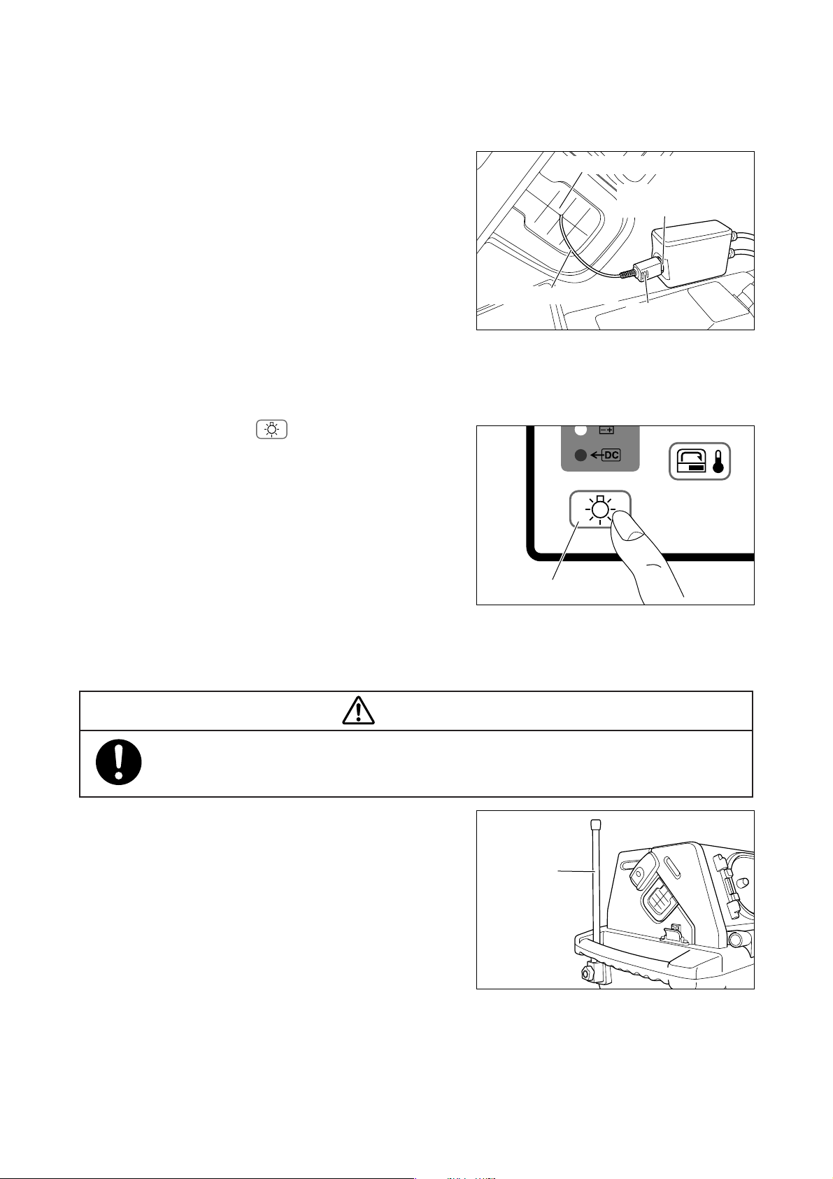
A number of cords and tubes may be connected to the
infant in the incubator. Insert them through a tube introduction slit packing into the incubator so that they may
not get in the way of procedures. The tube introduction
slit packing are provided on both sides of the hood.
7-2. Lighting Lamp
Press the lighting switch for one second, and the
lighting lamp will come on. Press it again, and the lighting lamp will go off.
Tube introduction slit packing
Skin temperature probe
connecting port
Skin temperature probe
(Plug)
7-3. I.V. Pole (Option)
WARNING
The maximum permissible load attachable to the I.V. pole is 3kg.
(1) An optional I.V. pole can be attached to either side
of the main body.
Lighting switch
I.V. pole
−39−
Page 42
7-4. Test Switch
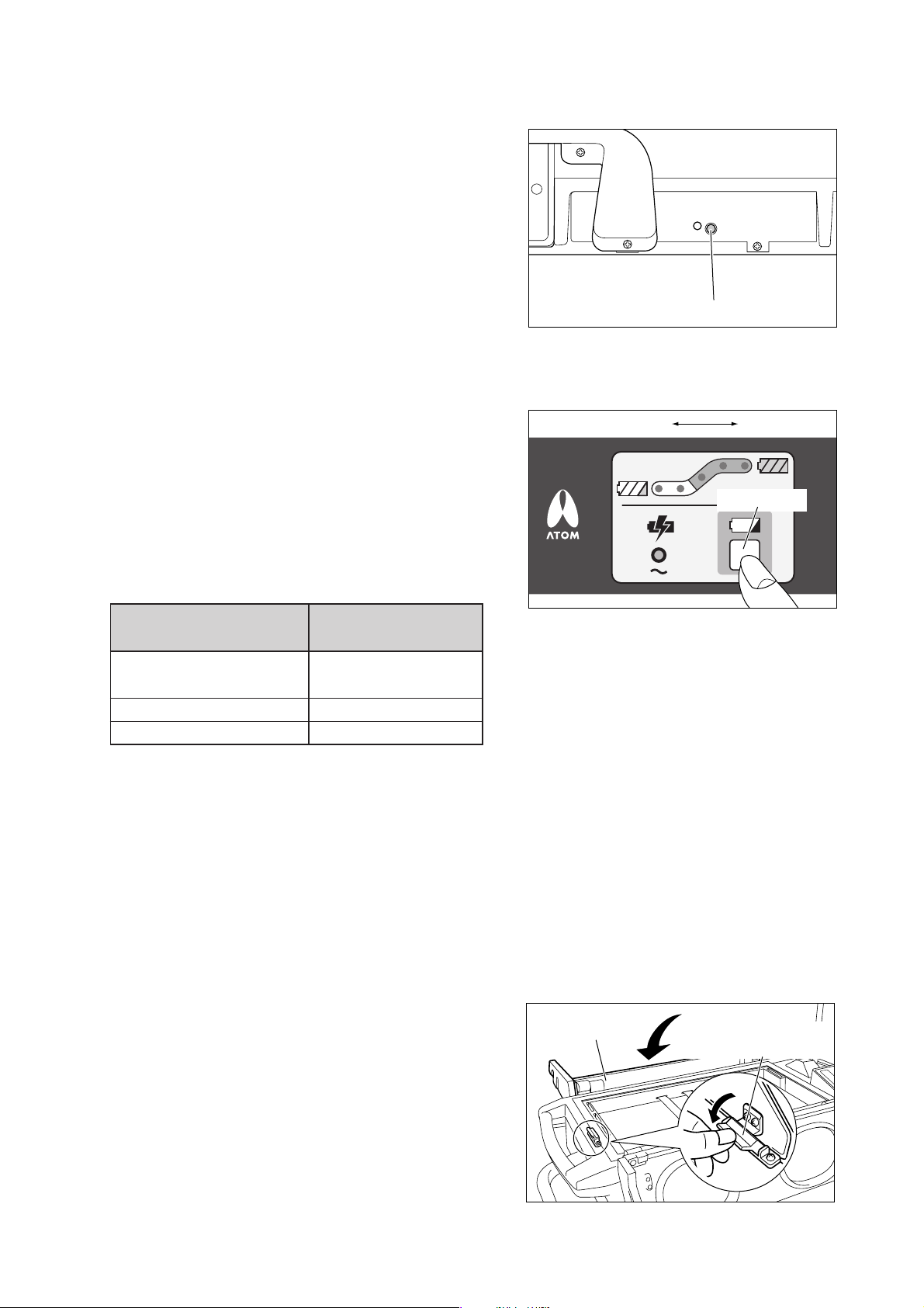
Press the test switch on the rear side of the main body
while the incubator is in operation, and all the LED indicators on the operation panel will illuminate and an audible alarm will sound. In this way you can check the “visual and audible” alarms for proper functioning.
7-5. Check Switch
Test Switch
Press the check switch on the power pack to check the
Battery charge level 0 Fully charged
battery charge level (voltage) of the power pack.
The LEDs indicating the battery charge level will not illuminate unless the check switch❉ is pressed.
Check switch
❉ Do not keep pressing the check switch. The power sup-
ply to the incubator will be stopped while the check
switch is being pressed to check the battery charge
level.
Battery charge level
Fully charged
(charged for 20 hours)
Near-empty
Empty
The number of
illuminating LEDs
5
2
0
쐽 Near-empty level
When the only two LEDs in the white range are on, recharge the battery as soon as possible.
If an AC power source (AC220-240V) is available, connect the power pack to the AC power source. You can
operate the unit and charge the battery at the same time.
쐽 When the Battery Deteriorates
When the battery deteriorates, the battery charge level indicator will automatically flash red.
7-6. Unlocking the Hood Lock (for opening the rear hood)
To open the rear hood for cleaning and disinfecting the
inside of the incubator, unlock the hood lock provided on
the left side at the bottom of the hood.
Unlock it and then let the hood fall back gently.
−40−
Hood (rear)
Hood Lock (for opening
the rear hood)
Page 43
[8] Cleaning and Disinfection
Before cleaning or disinfecting the unit, be sure to remove the power cord from the main body,
turn the power off, and allow the incubator air temperature and the heater temperature to fall
sufficiently.
Before cleaning or disinfecting the unit, check that the oxygen supply to the incubator has been
stopped and that the incubator has been disconnected from the oxygen supply source.
This product is shipped without being disinfected. Be sure to clean and disinfect the unit before
using it for the first time after purchase.
Before cleaning or maintaining the incubator, make sure that the oxygen supply to the incubator
has been stopped and that the incubator has been disconnected from the oxygen supply source.
Cleaning or maintaining the incubator in a high oxygen environment may cause a fire or an
explosion.
Clean and disinfect the unit whenever you use it for a new infant.
WARNING
Clean and disinfect the unit whenever you notice dirt or stain which might cause infection.
After cleaning and disinfection, assemble the removed parts correctly and perform an inspection
before use to ensure that the unit operates normally.
Obtain a soft clean cloth and a disinfectant solution for cleaning and disinfection.
쐽 Recommended disinfectant solutions include:
앫 Benzalkonium chloride aqueous solution (e.g. Osvan)
앫 Benzethonium chloride aqueous solution (e.g. Hyamine)
앫 Chlorhexidine aqueous solution (e.g. Hibitane)
Never use the above agents undiluted.
쐽 Do not use any abrasive cloth, cleaner, alcohol, acetone or other solvents for cleaning and disinfection. Do not
autoclave.
8-1. Skin Temperature Probe
Wipe a used probe lightly with a soft dr y cloth.
Disinfect the heat-sensing surface by wiping it with a soft cloth dampened with a disinfectant solution.
Be sure to keep the skin temperature probe in its case when storing it.
CAUTION
Never wipe the skin temperature probe with alcohol, or the probe material will harden.
−41−
Page 44
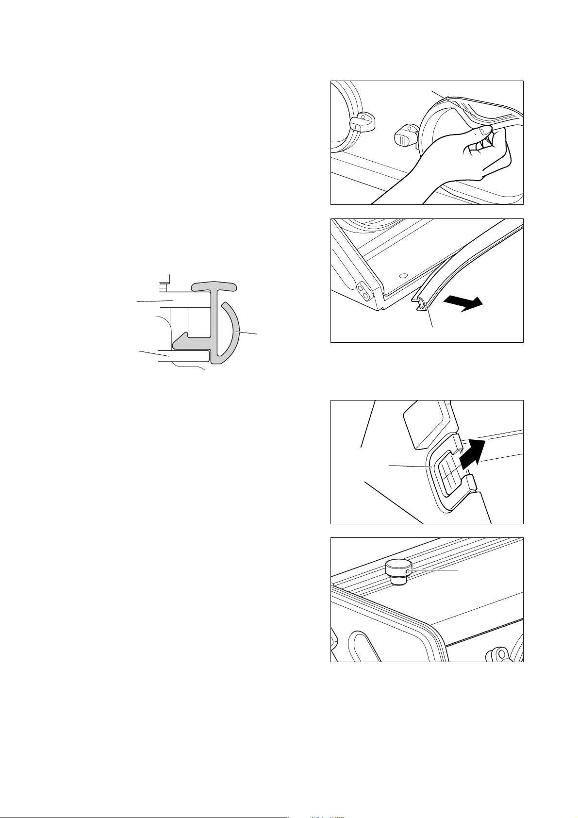
8-2. Hood
쎲 Snap-open access port packings
Remove the rubber packings from the snap-open access ports. Immerse and clean it in a disinfectant solution.
쎲 Front admittance panel packing
Remove the rubber packing from the front admittance
panel. Immerse and clean it in a disinfectant solution.
Outer wall of the front
admittance panel
Inner wall of the front
admittance panel
Front admittance
panel packing
Snap-open access
port packing
Front admittance panel packing
The front admittance panel with its packing installed
쎲 Tube introduction slit packing
Remove the packing from the tube introduction slit.
Immerse and clean it in a disinfectant solution.
쎲 Inner wall panel
(1) Loosen the fixing screws for the inner wall panels of
the hood and the front admittance panel respectively
and remove the inner wall panels.
(2) Clean both sides of each inner wall panel with a soft
cloth dampened with a disinfectant solution.
Tube
introduction
slit packing
Fixing screw
쎲 Hood and Front admittance panel
After removing the front admittance panel packing, the
tube introduction slit packing, the inner panels, and
the snap-open access port covers and packings, wipe
clean the inside and the outside of the hood and the
front admittance panel with a soft cloth dampened with
a disinfectant solution.
−42−
Page 45
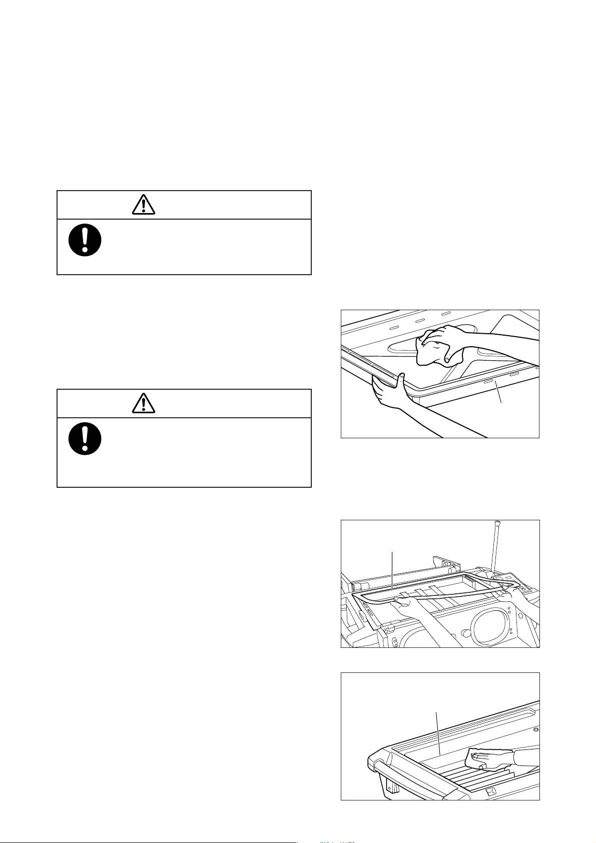
8-3. Mattress Platform
쎲 Mattress
The mattress consists of a special foam filling completely
sealed up in a vinyl cover. The foam filling inside cannot
be contaminated unless the cover gets damaged.
Remove the mattress before placing a new infant in the
incubator. Disinfect the mattress by immersing the entire mattress in a disinfectant solution.
CAUTION
Always have a spare sterile mattress available and
ready for use. Use only a sterile mattress whenever replacing the mattress for a new infant.
쎲 Mattress platform and infant fixing bands
(1) Pull out the mattress platform and wipe it clean with
a soft cloth dampened with a disinfectant solution.
(2) Remove the infant fixing bands from the mattress
platform and immerse them in a disinfectant solution. Dry them completely after disinfection.
CAUTION
It takes time for the infant fixing bands to dry completely. Always have spare sterile infant fixing
bands available and ready for use. Use only sterile fixing bands whenever replacing the bands.
쎲 Hood packing
Remove the hood packing from the conditioning chamber and immerse it in a disinfectant solution.
쎲 Conditioning chamber
Wipe clean the conditioning chamber with a soft cloth
dampened with a disinfectant solution.
Mattress platform
Hood packing
Conditioning chamber
−43−
Page 46
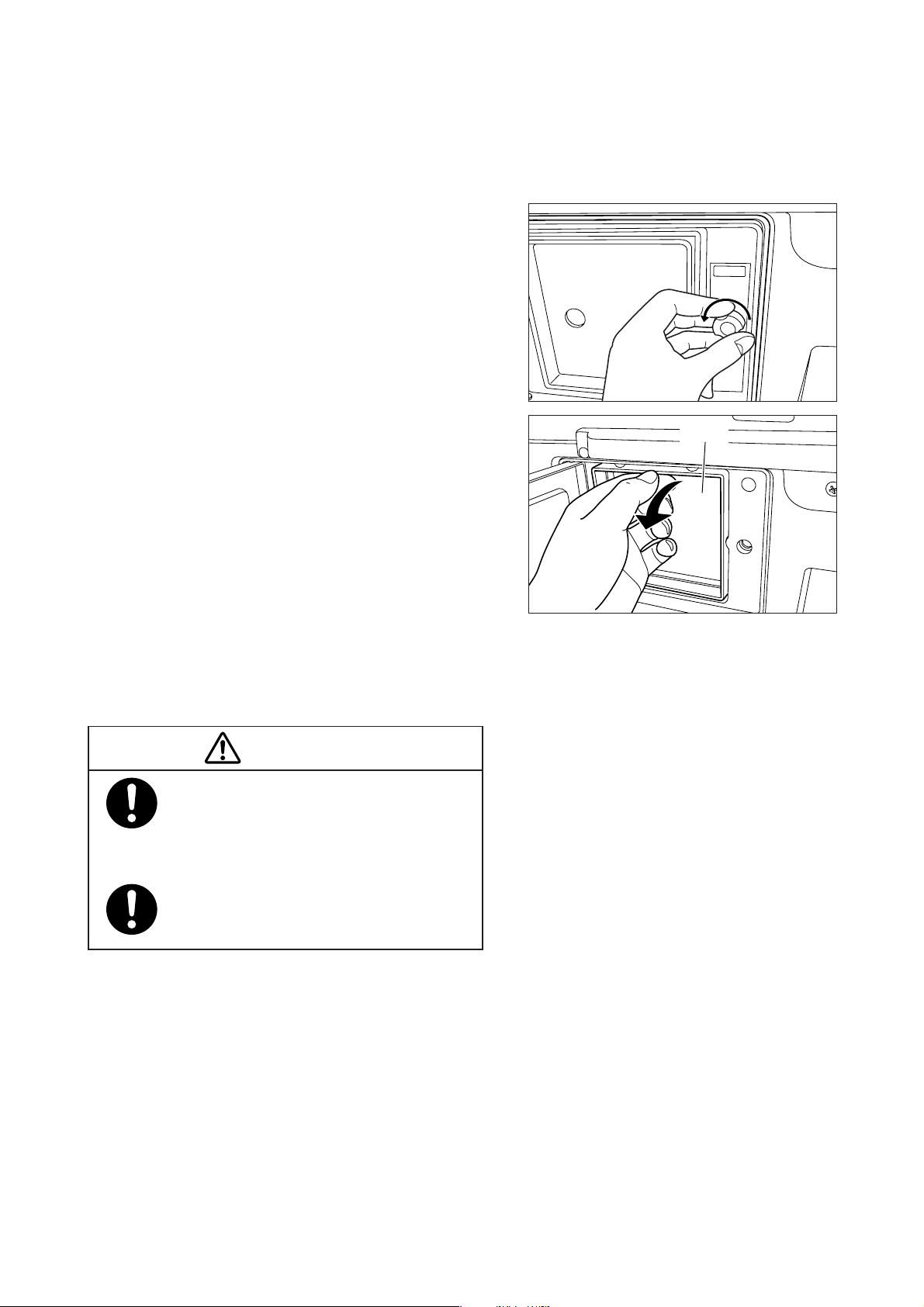
8-4. Replacing the Filter
The filter (Pneumoclean) should be replaced with a new one when its surface has been covered with dirt and
dust and they have penetrated into the filter. Do not attempt to reuse the dirty filter (Pneumoclean) by washing
it or attaching it inside out.
(1) Loosen the screw on the right side of the filter cover
and open the cover.
(2) Remove the dirty filter (Pneumoclean) with care in
order not to let the dirt and dust fly in all directions.
(3) Wipe clean the filter cover and the filter holder with
a soft cloth dampened with a disinfectant solution.
(4) Replace the dirty filter with a new one (Pneumoclean).
Close the cover and tighten the screw again.
CAUTION
The dirtiness of the filter varies with the degree of air pollution and the frequency of operation. Be sure to check the condition of the
filter frequently.
Filter
Use the Pneumoclean filter when replacing
the dirty filter for a new one.
−44−
Page 47
[9] Maintenance Inspection
To use the unit safely for a longer period, perform the maintenance inspections described below.
앫 Inspection before use
Check the basic functional operation of each part ever y time you are going to use the unit.
앫 Three-month inspection
Check the operation of each function on an every three month basis.
앫 Periodical inspection
Contact your local Atom representative for periodical inspection on an annual basis.
앫 Periodical replacement parts
Some parts need to be replaced periodically depending on their period of use.
CAUTION
Medical institutions are responsible for performing maintenance inspection.
They are allowed to entrust the maintenance inspection of the unit to an appropriate external dealer.
Before maintenance inspection, repair or disposal, clean and disinfect the unit and its accessories.
9-1. Daily Inspection
Check the following points every time you are going to use the unit.
Item to check
Appearance
Caster
Main body fixing band
Snap-open access port packing
Semi-iris access port cover
Front admittance panel
retainer
Hook slider of the snapopen access port
Filter
Oxygen supply port
Mattress platform
Power cord
Power indicator
Hood packing
Infant fixing band
Battery charge level
indicator
Test switch
Incubator air temperature
Skin temperature probe
sensor
The main body, the power supply, the power pack and the stand should be free of
breakage or deformation.
The casters should not be loose, shaky or broken. The casters with a stopper
should be able to be locked securely.
The main body fixing bands should be free of breakage.
They should be able to fix the main body securely to the stand.
Each packing should be attached correctly to the hood.
The semi-iris access port cover should be attached securely to the iris access
port ring. It should be free of breakage or deformation.
The retainers should not be loose, shaky or broken. They should be able to lock
the front admittance panel securely.
The hook sliders should not be loose. They should be able to lock the snap-open access
ports securely. They should be able to open and close the snap-open access por ts reliably.
The filter should be clean.
The oxygen supply port should not be loose or shaky.
The mattress platform should be free of breakage.
The power cord should be free of breakage.
An appropriate power indicator should illuminate depending on the power source
being used for operation.
The packing should be attached correctly to the main body.
The infant fixing bands should be attached to the mattress platform.
All the five LEDs of the battery charge level indicator should illuminate when the
check switch is pressed.
All the LED indicators should illuminate and an audible alarm should sound when
the test switch is pressed.
The sensor should be free of breakage or deformation.
The probe should be free of breakage or deformation.
Description
−45−
Page 48

9-2. Three-month Inspection
Check the following points on an every three-month basis.
Item to check
Incubator air tem-
perature control
Lighting lamp
Fan
Battery
Set the incubator air temperature to 36˚C.
Operate the switch of the lighting lamp.
Check the exterior appearance by visual inspection.
Charge the battery for at least 20 hours and
stabilize the incubator air temperature at
36˚C.
Procedure
Description
The displayed incubator air temperature
should be stable at 36.01˚C.
The lamp should come on when the
lighting switch is pressed, and should
go off when the switch is pressed again.
The fan should not make a strange
sound. It should not be loose, broken
or deformed.
The unit should operate for at least 90
minutes on the battery power with the
ambient temperature at 15˚C.
9-3. Periodical Replacement Parts
Periodical replacement parts are those which gradually deteriorate and wear down with use. They need periodical replacement to keep the accuracy and performance of the unit at a proper level. Timing of replacement
varies with the frequency and conditions of use. Consult your local Atom representative.
Part name
Wide type snap-open access port
rubber packing (for semi-iris port)
Semi-iris access port cover
Front admittance panel packing
Hook slider
Mattress
Fan
12V lead-acid battery
(internal battery)
Battery for power failure alarm
Filter (Pneumoclean)
Hood packing
Fan cover catch
Period of use
1-2 years
3-6 months
1-2 years
2 years
1-2 years
2-3 years
Variable depending on
operating conditions
Variable depending on
operating conditions
1000 hours or 2 months
1-2 years
2 years
Reason for replacement
Decreased air tightness due to breakage or deformation
Decreased air tightness due to breakage or deformation
Decreased air tightness due to breakage or deformation
Defective locking due to breakage or deformation
Deterioration, breakage or decreased elasticity
due to repeated use or disinfection
Deterioration or breakage due to repeated use or
disinfection
Poor operation on battery power due to a battery
life
No retention of data or information stored in the
memory
Dirtiness due to dir t and dust
Decreased air tightness due to breakage or deformation
Defective locking due to breakage or deformation
−46−
Page 49
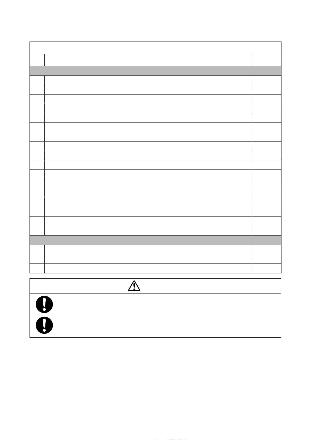
9-4. Inspection Checklist
Serial NO. ( ) Date of inspection ( . . ) Inspector ( )
NO.
Inspection before use (every time)
1
Are the main body, the power pack and the stand free of breakage or deformation?
2
Is the main body fixed securely to the stand?
3
Are the casters attached securely and tightly? Can the casters be locked securely with the stoppers?
4
Are the main body fixing bands free of breakage? Can they fix the main body securely to the stand?
5
Is each snap-open access port packing attached correctly to the hood?
Is each semi-iris access port cover free of breakage or deformation? Is it attached securely to
6
the snap-open access port packing?
7
Are the hook sliders attached securely? Can they lock the snap-open access ports securely?
8
Is the filter clean?
9
Is the oxygen supply port attached securely and tightly?
10
Is the mattress platform free of breakage?
Are the front admittance panel retainers free of breakage? Can they lock the front admit-
11
tance panel securely?
Does the AC power indicator, the battery power indicator or the external DC power indicator
12
illuminate appropriately depending on the power source being used for operation?
Item to check
Judgement
YES / NO
YES / NO
YES / NO
YES / NO
YES / NO
YES / NO
YES / NO
YES / NO
YES / NO
YES / NO
YES / NO
YES / NO
13
Is the hood packing attached correctly to the mattress platform?
14
Are the infant fixing bands free of breakage? Are they attached to the mattress platform?
Three-month inspection
Is the incubator air temperature stable at 36˚C when it is set to 36˚C (with the ambient tem-
1
perature at 20˚C)?
2
Does the lighting lamp come on when the lighting switch is pressed?
CAUTION
If any trouble should be detected in either inspection, indicate on the unit that it is out of order and
be sure to have it repaired.
Contact your local Atom representative for further information on ser vicing or repairs.
YES / NO
YES / NO
YES / NO
YES / NO
−47−
Page 50

9-5. Disposal
The main body, the packing materials, any parts beyond the life and disposables should be disposed of properly by the medical institution concerned according to applicable waste disposal laws and regulations.
The unit contains a rechargeable lead-acid battery and a rechargeable nickel metal hydride batter y. Follow
proper disposal procedures to dispose of the batteries.
−48−
Page 51

[10] Alarms and Alerts
(1) High temperature alarm
The high temperature alarm indicator will illuminate and an audible alarm will sound before the incubator
air temperature exceeds 39.0˚C. At the same time, the power supply to the heater will be shut off.
Action to take: The high temperature alarm can be reset by pressing the alarm silence/reset switch after
the incubator air temperature has fallen to a normal level.
(2) Fan alarm
If the fan for circulating the air in the incubator has stopped or isn’t attached properly, the fan alarm
indicator will illuminate and an audible alarm will sound. At the same time, the power supply to the heater
will be shut off.
Action to take: Eliminate all the causes. After checking that the fan rotates normally, start the operation
again.
(3) Power failure alarm
If the power supply is interrupted during the operation, the power failure alarm indicator will illuminate
and an audible alarm will sound.
Action to take: Check the power source, connections, and the breaker.
Eliminate all the causes and start the operation again.
(4) Set point alarm
If a displayed incubator air temperature deviates from the set temperature by 3˚C or more, the set point
alarm indicator will illuminate and an audible alarm will sound. The power supply to the heater will be shut
off if the displayed incubator air temperature exceeds the set temperature by 3˚C or more. It will not be
shut off if the displayed incubator air temperature falls below the set temperature by 3˚C or more. At this
time, the audible alarm can be silenced temporarily by pressing the alarm silence/reset switch.
The set point alarm will not activate for 30 minutes after the power is applied. However, the set point alarm
will activate even during the first 30 minutes once the incubator air temperature has reached the set
temperature 3˚C.
Action to take: Check whether an air outlet, an air inlet or the incubator air temperature sensor is cov-
ered with sheets or other materials. If no trouble is found with the above items, the incubator should be regarded as out of order. Stop using the incubator and contact your local
Atom representative.
(5) Silence alarm
If the set point alarm is silenced by pressing the alarm silence/reset switch, the alarm silence indicator
will illuminate to indicate visually that the audible alarm is silenced. If another alarm should occur while
the audible alarm is silenced, the audible alarm will be reset automatically and begin to sound. The audible
alarm will stop automatically when the alarm condition is over. If the alarm condition should continue for
15 minutes or longer, the audible alarm will sound again.
−49−
Page 52

(6) System failure alarm
If a wire of the high temperature sensor or the incubator air temperature sensor gets broken or shortcircuited, the system failure alarm indicator will illuminate, an error message will appear on the incubator
air temperature display and an audible alarm will sound. At the same time, the power supply to the heater
will be shut off.
In this case, the audible alarm cannot be silenced by pressing the alarm silence/reset switch. Turn the
power off and star t the operation again.
Action to take: When a system failure has occurred, the cause of the trouble can be roughly identified by
checking the error message on the incubator air temperature display. If the error message is [ ], [ ], [ ] or [ ], the possible cause is a failure of the incubator
air temperature sensor or the sensor module. Turn the power off and check the connection of the sensor module. If the error message is [ ] or [ ], the possible cause is
a failure of the relay board or the heater. If the error message is [ ] or [ ], the
possible cause is a failure of the main board. If the same alarm message continues to be
displayed, stop using the incubator and contact your local Atom representative.
(7) Skin temperature probe alarm
If any trouble should occur to the skin temperature probe, the skin temperature display will flash and an
audible alert will sound.
Action to take: A wire of the skin temperature sensor may have got broken or short-circuited. Replace
the skin temperature probe with a new one.
(8) Low voltage alarm
If the supply voltage to the main body should drop while the unit is being powered, an appropriate power
indicator will flash and an audible alert will sound ever y 15 seconds.
Action to take: When the power pack or the external DC power source is being used to power the unit,
connect the power pack to the AC power source. (The battery charge level of the power
pack may have decreased. Recharge the power pack for at least 20 hours.)
(9) Power pack alarm
If a problem occurs with the battery, the battery charge level indicator on the power pack will automatically flash red in warning.
Action to take: Replace the battery, as this may be due to battery deterioration. When this alarm occurs,
stop using the unit and contact your local Atom representative.
−50−
Page 53
[11] Troubleshooting
Check the following points before requesting repair service.
CAUTION
Trouble
Nothing is displayed on the opera-
tion panel of the incubator.
The power indicator of the power
pack does not illuminate.
The battery of the power pack
cannot be charged.
The incubator air temperature rises
too high.
The incubator air temperature does
not rise.
The oxygen concentration does not
rise.
The skin temperature is not displayed.
Check
쎲 Is the power switch of the incubator turned off?
쎲 Is the power input connector of the incubator connected securely to
the power output connector of the power pack with the connecting
cord?
쎲 Is the breaker of the incubator tripped (protruded)?
쎲 Has the power input fuse (20A) of the power pack blown?
쎲 Is the battery of the power pack charged?
Press the check switch to check the battery charge level. (If the
battery voltage should fall during the operation, the low voltage alarm
will occur.)
[Check the following as well if the unit is operating on a car battery.]
쎲 Has the car fuse blown?
쎲 Is the plug of the power cord disconnected from the power outlet?
쎲 Has the power input fuse (2.5 A) blown?
쎲 Is the plug of the power cord disconnected from the power outlet?
쎲 Has the power input fuse (2.5 A) blown?
쎲 Is the incubator air temperature set too high?
쎲 Is the incubator exposed to direct sunshine or affected by a heating
apparatus nearby?
쎲 Is the incubator air temperature set too low?
쎲 Is the supply voltage of the battery of the power pack low?
쎲 Is the incubator exposed directly to a cold wind of air-conditioner?
쎲 Is oxygen being supplied reliably?
쎲 Is the oxygen cylinder empty?
쎲 Check the flow rate on the oxygen flowmeter.
쎲 Is the connecting hose disconnected from the incubator?
쎲 Is the skin temperature probe connected properly?
WARNING
If the unit seems to be defective, indicate on the unit that it is out of order and contact your local
Atom representative.
−51−
Page 54

[12] Technical Data
Power requirements
Classification
Operating conditions
AC power source AC220AC240V 10%
50/60Hz
220VA
Power pack Capacity : DC12V, 24Ah (one lead-acid battery)
Charging time : Approx. 20 hours
Continuous operation : Approx. 90 minutes (ambient temperature at 15˚C, incubator air temperature
stable at 36˚C)
External DC power source Rating : DC12V, 10A
Operating voltage range : DC11.014.0V
Type of protection : Class I/ internally powered equipment
Degree of protection : Type BF applied par t
Ingress of water : The enclosure not protected against the ingress of water
Not for use in air and a flammable anesthetic gas or oxygen/nitrous oxide and a
flammable anesthetic gas
Mode of operation : Continuous operation
Ambient temperature : 1030˚C
Relative humidity : 3075%
Atmospheric pressure : 70106kPa
Airflow velocity : 0.31.0m/s
Storage conditions/
Tr ansport conditions
Tr ansport conditions
Dimensions
Weight
Maximum load
Accessories
Ambient temperature : 050˚C
Relative humidity : 3075%
Atmospheric pressure : 70106kPa
To be transported with the stand at the lowest level
Main body : 95(W) 44(D) 42(H)cm
HL Stand : 100(W) 45(D) 48-80(H)cm
Cabinet stand for internal hospital use : 97(W) 45(D) 74(H)cm
Mattress : 56(W) 28(D) 2(T)cm
Power pack : 29(W) 17.5(D) 25(H)cm
Main body : Approx. 17kg
HL Stand : Approx. 28kg
Cabinet stand for internal hospital use : Approx. 26kg
Power pack : Approx. 13kg
Cabinet stand for internal hospital use (option): Approx. 20kg
I.V pole (option): Approx. 3kg
Skin Temp Probe, O.D.(Yellow) Cable Length:90cm ......... 1
Semi-iris access port cover .................................................... 2
Infant fixing band .................................................................... 3
Dust cover ............................................................................... 1
Main body fixing band ........................................................... 2
Pneumoclean ........................................................................... 1
Operation manual ................................................................... 1
−52−
Page 55

쐽 Temperature/humidity
Incubator air temperature control
Incubator air temperature setting range
Incubator air temperature display range
Heater output
Warm-up time
Humidifying function
Time proportional control
23.038.0˚C in 0.1˚C increments
20.042.0˚C in 0.1˚C increments, accuracy : 1.0˚C
0100 (in 10 levels)
Approx. 40 minutes (ambient temperature at 25˚C)
None
쐽 Skin temperature display
Display range
Display accuracy
30.042.0˚C in 0.1˚C increments
0.3˚C
쐽 Alarms/Alerts
Alarm
High temperature, set point, power failure, fan, system failure, silence, power
pack, skin temperature probe, low voltage (when the voltage from the battery or
the external DC power source falls to approx.10.5V)
쐽 Oxygen supply
Max. oxygen concentration
Achieving time
쐽 Environment
CO2 concentration in the hood
쐽 EMC
Electromagnetic compatibility
60% (oxygen flow rate 10L/min)
30 minutes (from 21% to 55%, O2 flow rate 10L/min)
CO2 concentration stabilized after a mixture of air and 4% CO2 is administered to
a point 10 cm above the center of the mattress at 750ml/min should not exceed
0.5%.
This product meets the requirements of the international standard IEC60601-1-2.
−53−
Page 56

[13] EMC level and Classification
Guidance and manufacture’s declaration - electromagnetic emissions
The V-707 is intended for use in the electromagnetic environment specified below. The user of V-707 should
assure that it is used in such an environment.
Emission Test
RF emission
CISPR 11
RF emission
CISPR 11
Harmonic emission
IEC 61000-3-2
Voltage fluctuations
/flicker emission
IEC 6100-3-3
Compliance
Group 1
Class B
Class A
Complies
Electromagnetic environment - guidance
The V-707 uses RF energy only for its internal function. Therefore, its RF emissions are very low and
are not likely to cause any interference in nearby
electronic equipment.
The V-707 is suitable for use in all establishments,
including domestic establishments and those directly connected to the public low-voltage power
supply network that supplies building used for domestic purposes.
Guidance and manufacture’s declaration - electromagnetic immunity
The V-707 is instended for use in the electromagnetic environment specified below. The user of V-707 should
assure that it is used in such an environment.
Immunity
test
Electrostatic discharge (ESD)
IEC 61000-4-2
Electrical fast transient / burst
IEC 61000-4-4
IEC 60601 test
level
6kV contact
8kV air
2kV power
supply line
Compliance
level
6kV contact
8kV air
2kV power
supply line
Electromagnetic environment -
guidance
Floor should be wood, concrete or
ceramic tile. If floors are covered with
synthetic material, the relative humidity should be at least 30%.
Mains power quality should be that
of a typical commercial or hospital
environment.
Surge
IEC 61000-4-5
1kV differential
mode
2kV common
mode
1kV differential
mode
2kV common
mode
−54−
Mains power quality should be that
of a typical commercial or hospital
environment.
Page 57

Guidance and manufacture’s declaration - electromagnetic immunity
The V-707 is instended for use in the electromagnetic environment specified below. The user of V-707 should
assure that it is used in such an environment.
Immunity
test
Voltage dips, short inter-
ruptions and voltage
variations on power supply
input lines.
IEC 61000-4-11
NOTE : UT is the A.C. mains voltage prior application of the test level.
Power frequency
(50/60Hz)
magnetic field
IEC 61000-4-8
IEC 60601 test
level
5% U
T
( 95% dip in UT)
for 0.5 cycles
40% U
T
(60% dip in UT)
for 0.5 cycles
70% U
T
(30% dip in UT)
for 25 cycles
5% U
T
( 95% dip in UT)
for 5 sec
3(A/m)
Compliance
level
5% U
T
( 95% dip in UT)
for 0.5 cycles
40% U
T
(60% dip in UT)
for 0.5 cycles
70% U
T
(30% dip in UT)
for 25 cycles
5% U
T
( 95% dip in UT)
for 5 sec
3(A/m)
Electromagnetic environment -
guidance
Mains power quality should be that
of a typical commercial or hospital
environment.
If the user of the V-707 requires continued operation during power mains
interruptions, V-707 is powered from
an uninterruptible power supply.
Power frequency magnetic fields
should be at levels characteristic of
a typical location in a typical com-
mercial or hospital environment.
−55−
Page 58

Guidance and manufacture’s declaration - electromagnetic immunity
The V-707 is instended for use in the electromagnetic environment specified below. The user of V-707 should
assure that it is used in such an environment.
Immunity
test
Conducted RF
IEC 61000-4-6
Radiated RF
IEC 61000-4-3
NOTE 1 : Portable / mobile RF communications equipment should be used no closer to any part of the V-
707, than the recommended separation distance calculated from the equation applicable to the
frequency of the transmitter.
NOTE 2 : Where P is the maximum output power rating of the transmitter in watts(W) according to the
transmitter manufacturer and d is the recommended separation distance in meters(m).
NOTE 3 : At 80MHz and 800MHz, the higher frequency range applies.
NOTE 4 : These guidelines may not apply in all situation. Electromagnetic propagation is affected by ab-
sorption and reflection from structures, objects and people.
NOTE 5 : The ISM (industrial, scientific and medical) bands between 150kHz and 80MHz are 6.765MHz to
6.795MHZ; 13.553MHz to 13.567MHz; 26.957MHz to 27.283MHz; and 40.66MHz to 40.70MHz.
NOTE 6 : An additional factor of 10/3 is used in calculating the recommended separation distance for
transmitters in the ISM frequency bands to decrease the likelihood that mobile/portable com-
munication equipment could cause interface if it is inadver tently brought into patient areas.
NOTE7 : Field strengths from fixed transmitters, such as base stations for radio (cellular/cordless) tele-
phones and land mobiles radios, amateur radio AM and FM radio broadcast and TV broadcast
cannot be predicated theoretically with accuracy. To assess the electromagnetic environment
due to fixed RF transmitters, an electromagnetic site survey should be considered. If the mea-
sured field strength in the location in which the V-707 is used exceeds the applicable RF compli-
ance level above, additional measures may be necessary, such as re-orienting or relocating the V-
707.
NOTE 8 : Interference may occur in the vicinity of equipment marked the following symbol:
IEC 60601 test
level
3Vrms
(150kHz to 80MHz)
outside ISM bands
10Vrms
(150kHz to 80MHz)
in ISM bands
10Vrms
(80kHz to 2.5GMHz)
Compliance
level
10Vrms
(0.1580MHz,
1% step)
10V/m
Electromagnetic environment -
guidance
Recommended separation distance
d = 0.35 P , outside ISM bands
d = 0.35 P , in ISM bands
Recommended separation distance
d = 1.2 P , 80MHZ ~ 800MHZ
d = 2.3 P , 800MHZ ~ 2.5GHZ
−56−
Page 59

Recommended separation distances between
Portable / mobile RF communications equipment and V-707
The V-707 is intended for use in the electromagnetic environment in which radiated RF disturbances are
controlled. The user of the V-707 can help prevent electromagnetic interference by maintaining a minimum
distance between portable/mobile RF communications equipment (transmitters) and the V-707 as recommend below, according to the maximum output power of the communication equipment.
Rated maximum
output power of
transmitter
W
0.01
0.1
1
10
100
NOTE 1: Where P is the maximum output power rating of the transmitter in watts(W) according to the
transmitter manufacturer and d is the recommended separation distance in meters(m).
NOTE 2 : At 80MHz and 800MH, the higher frequency range applies.
NOTE 3 : The ISM (industrial, scientific and medical) bands between 150kHz and 80MHz are 6.765MHz to
6.795MHz; 13.553MHz to 13.567MHz; 26.957MHz to 27.283MHz; and 40.66MHz to 40.70MHz.
NOTE 4 : These guidelines may not apply in all situations. Electromagnetic propagation is affected by
absorption and refection from structure, objects and people.
150kHz to 80MHz
outoside ISM bands
d(m) = 0.35 P
Separation distance according to frequency of transmitter
m
0.035
0.11
0.35
1.1
3.5
150kHz to 80MHz
In ISM bands
d(m) = 1.2 P
0.12
0.38
1.2
3.8
12
80MHz to 800MHz
d(m) = 1.2 P
0.12
0.38
1.2
3.8
12
80MHz to 2.5GHz
d(m) = 2.3 P
0.12
0.38
1.2
3.8
12
−57−
Page 60

[14] Accessories, Supplementary Equipment, Used Material
Part name Material
Snap-open access port PVC
Snap-open access port packing PVC
Semi-iris access port cover PVC
Front admittance panel packing PVC
Tube introduction slit packing Silicone rubber
Mattress PVC
Mattress platform PVC/PMMA
Fan PP
Filter (Pneumoclean) PP
Hood packing PVC
−58−
Page 61

Page 62

Page 63

The unit for use in 100V regions doesn’t meet the requirements for CE marking.
For further information or questions, please contact the following representative if you are in an EU member
state. If you are not in an EU member state, please contact your local Atom representative.
Page 64

C64MC017
18-15, Hongo 3-chome, Bunkyo-ku, Tokyo, Japan
Tel: +81 3 38152311 Fax: +81 3 38123144
201801
 Loading...