

Atomic G01342W User Manual

y t i l a u q t s e h g i h e h t f o e r a s t c u d o r p r u o t a h t e r u s n e o t e v i r t s e W
e r f d n a
f i , r e v e w o H . s t r a p g n i s s i m r o s t c e f e d g n i r u t c a f u n a m f o e
, t c u d o r p w e n r u o y h t i w s m e l b o r p y n a e v a h u o y
E R O T S E H T O T T I N R U T E R T O N O D ,
: @ e e r f l l o t s u t c a t n o c e s a e l p
888-996-2729 - 1
1 3 5 3 - 3 7 8 - 6 6 8 - 1 : X A F
m o c . s t r o p s e d a l a c s e @ gameroom
: o t e t i r w r O
s t r o p S e d a l a c s E
t n e m t r a p e D e c i v r e S r e m o t s u C
9 8 8 x o B . O . P
6 0 7 7 4 N I , e l l i v s n a v E
. s t r a p t u o b a g n i r i u q n i n e h w dat e code r u o y e v a h e s a e l P
date code (if , r e b m u n l e d o m r u o y e d i v o r p e s a e l p s t r o p S e d a l a c s E g n i t c a t n o c n e h W
e r a g n i t s e u q e r f i r e b m u n t r a p d n a , ) e l b a c i l p p a
. l a u n a m s r e n w o s i h t n i d n a , g n i g a k c a p , t c u d o r p e h t n o d e t a c o l
G01342W
r e b m u N l e d o M r u o Y
Dat e Code:
Purchase Date:
PLEASE RETAIN THIS INSTRUCTION MANUAL FOR FUTURE REFERENCE
All Rights Reserved
2 - G01342W - - WJ
888-996-2729 - 1 l l a C e c i v r e S r e m o t s u C r o F 1 s t r o p S e d a l a c s E 120 2 ©
e r a s r e b m u n e s e h T . t r a p t n e m e c a l p
IMPORTANT! READ EACH STEP
IN THIS MANUAL BEFORE YOU
BEGIN THE ASSEMBLY.
TWO
ADULTS ARE REQUIRED TO ASSEMBLE
THIS ATOMIC PROFORCE SOCCER TABLE
Tools Required:
T1 - Allen Wrench (Included)
Phillips Screwdriver
Furniture Polish and Cloth
Assembly Tips
Make sure you understand the following tips before you begin to assemble your soccer table.
1. Start all bolts by hand before tightening.
2. Some drawings or images in this manual may not look exactly like your product. Please
read and understand the text before starting each assembly step.
READ AND FOLLOW ALL ASSEMBLY, OPERATION, AND
SAFETY INSTRUCTIONS CAREFULLY. AT LEAST TWO
ADULTS ARE NEEDED TO PUT THIS SOCCER TABLE
TOGETHER.
All Rights Reserved.
©
2012 Escalade Sports
2
For Customer Service Call 1-888-996-2729
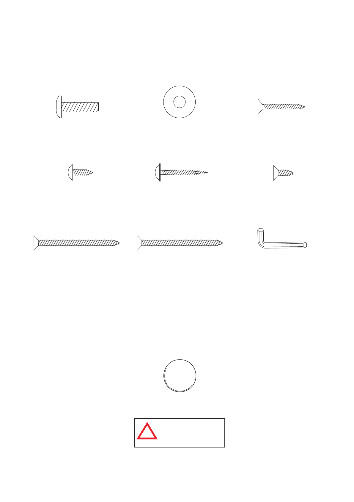
HARDWARE IDENTIFIER
( To Scale)
H1 - 6mm x 22mm
Allen Head Bolt
(16 pcs)
H4 - 4mm x 12mm
Phillips Round Head
Screw (84 pcs)
H7 - 4mm x 51mm
Phillips Flat Head
Screw (12 pcs)
H2 - 6mm x 19mm
Flat Washer (16 pcs)
H5 - 3mm x 28mm
Phillips Washer Head
Screw (18 pcs)
H8 - 4mm x 51mm
Zinc - Phillips Flat Head
Screw (4 pcs)
H3 - 3mm x 28mm
Phillips Flat Head
Screw (8 pcs)
H6 - 4mm x 12mm
Phillips Flat Head
Screw (6 pcs)
(Not to Scale)
T1 - Allen Wrench
(1 pc)
All Rights Reserved.
©
2012 Escalade Sports
ACCESSORIES IDENTIFIER
( Not to Scale)
A1- Soccer Ball (4 pcs)
WARNING:
CHOKING HAZARD
!
Small parts.
Not for children under 3 yrs.
3
For Customer Service Call 1-888-996-2729

PARTS IDENTIFIER
( Not to Scale)
P1 - Side Apron
(2 pcs)
P5 - End Top Rail
(2 pcs)
P9 - Bottom Goal
Box (2 pcs)
P2 - End Apron
(2 pcs)
P6 - Goal End
Board (2 pcs)
P10 - Scorer (2 pcs)
P3 - Leg (4 pcs)
P7 - Playfield Support
Brace (2 pcs)
P11 - Leg Leveler
(4 pcs)
P4 - Playfield (1 pc)
P8 - Top Goal
Box (2 pcs)
P12 - Playfield
Trim (2 pcs)
P13 - Plastic Rod
Washer (16 pcs)
P17 - Outside Ball
Entry Cup (2 pcs)
All Rights Reserved.
©
2012 Escalade Sports
P14 - Rod Bumper
(16 pcs)
P18 - Plastic
Bracket (18 pcs)
P15 - Rod End
Cap (8 pcs)
P16 - Rod Handle
(8 pcs)
WARNING:
CHOKING HAZARD
!
Small parts.
Not for children under
3 yrs.
4
For Customer Service Call 1-888-996-2729
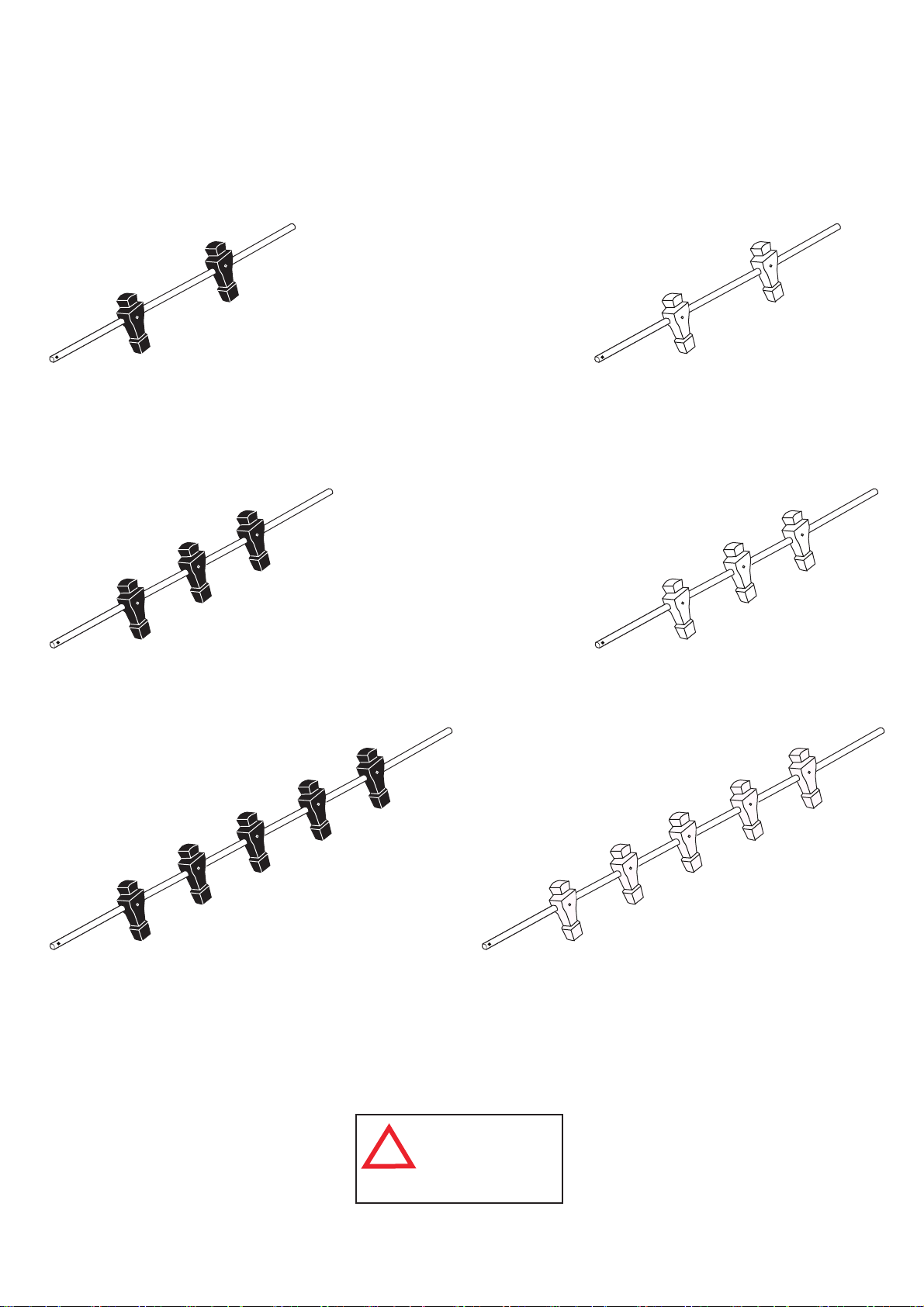
ROD IDENTIFIER
( Not to Scale)
R1 - 2 Player Rod
Assembly Black (1 pc)
R2 - 3 Player Rod
Assembly Black (2 pcs)
R4 - 2 Player Rod
Assembly Ivory (1 pc)
R5 - 3 Player Rod
Assembly Ivory (2 pcs)
R3 - 5 Player Rod
Assembly Black (1 pc)
All Rights Reserved.
©
2012 Escalade Sports
WARNING:
CHOKING HAZARD
!
Small parts.
Not for children under
3 yrs.
5
R6 - 5 Player Rod
Assembly Ivory (1 pc)
For Customer Service Call 1-888-996-2729
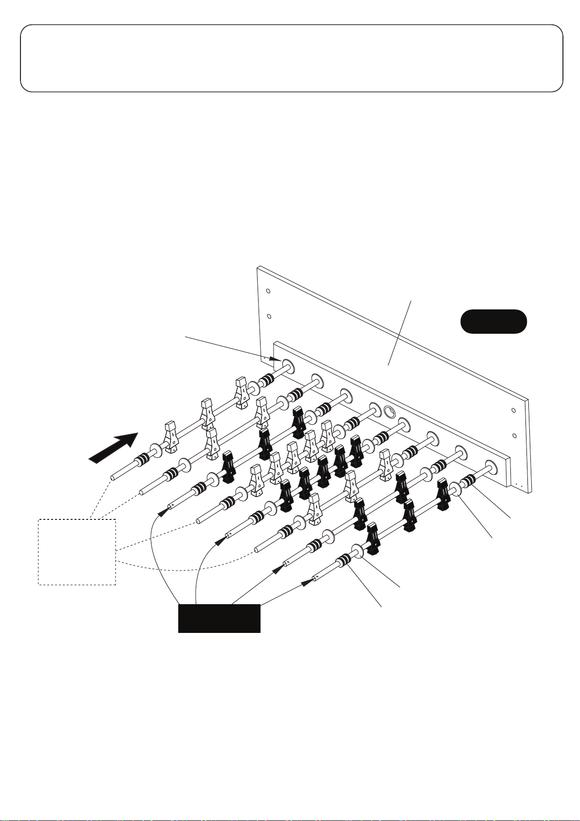
PARTS REQUIRED:
1 pc - P1 Side Apron 1 pc - R1 2 Player Rod Assembly Black 1 pc - R4 2 Player Rod Assembly Ivory
16 pcs - P13 Plastic Rod Washer 2 pcs - R2 3 Player Rod Assembly Black 2 pcs - R5 3 Player Rod Assembly Ivory
16 pcs - P14 Rod Bumper 1 pc - R3 5 Player Rod Assembly Black 1 pc - R6 5 Player Rod Assembly Ivory
STEP 1:
Find a clean, level place to begin the assembly of your soccer table. We recommend building the table on the
box top to protect the parts during assembly.
Attach P13 Plastic Rod Washer and P14 Rod Bumper to the rods as shown in FIGURE 1. Place one P1 Side
Apron UPSIDE DOWN with the laminated side facing out as shown in FIGURE 1.
Align the rods as shown in FIGURE 1.
Please note the location of the hole that is near one end of each rod. This is the handle end of the rod.
There will be four handles on each side of the table. It is critical that you set the rods as shown below so
the table will be correct when flipped over.
C1 Rod Bushing
Note: C1 Rod Bushings
are already attached
onto P1 Side Apron
R4, R5 and R6
Hole/Handle
goes on the
other end of
these rods
R5
R4
R2
R6
R3
R5
R1
R2
P1
FIGURE 1
P14
P13
P13
All Rights Reserved.
©
2012 Escalade Sports
R1, R2 and R3
Hole/Handle End
P14
6
For Customer Service Call 1-888-996-2729
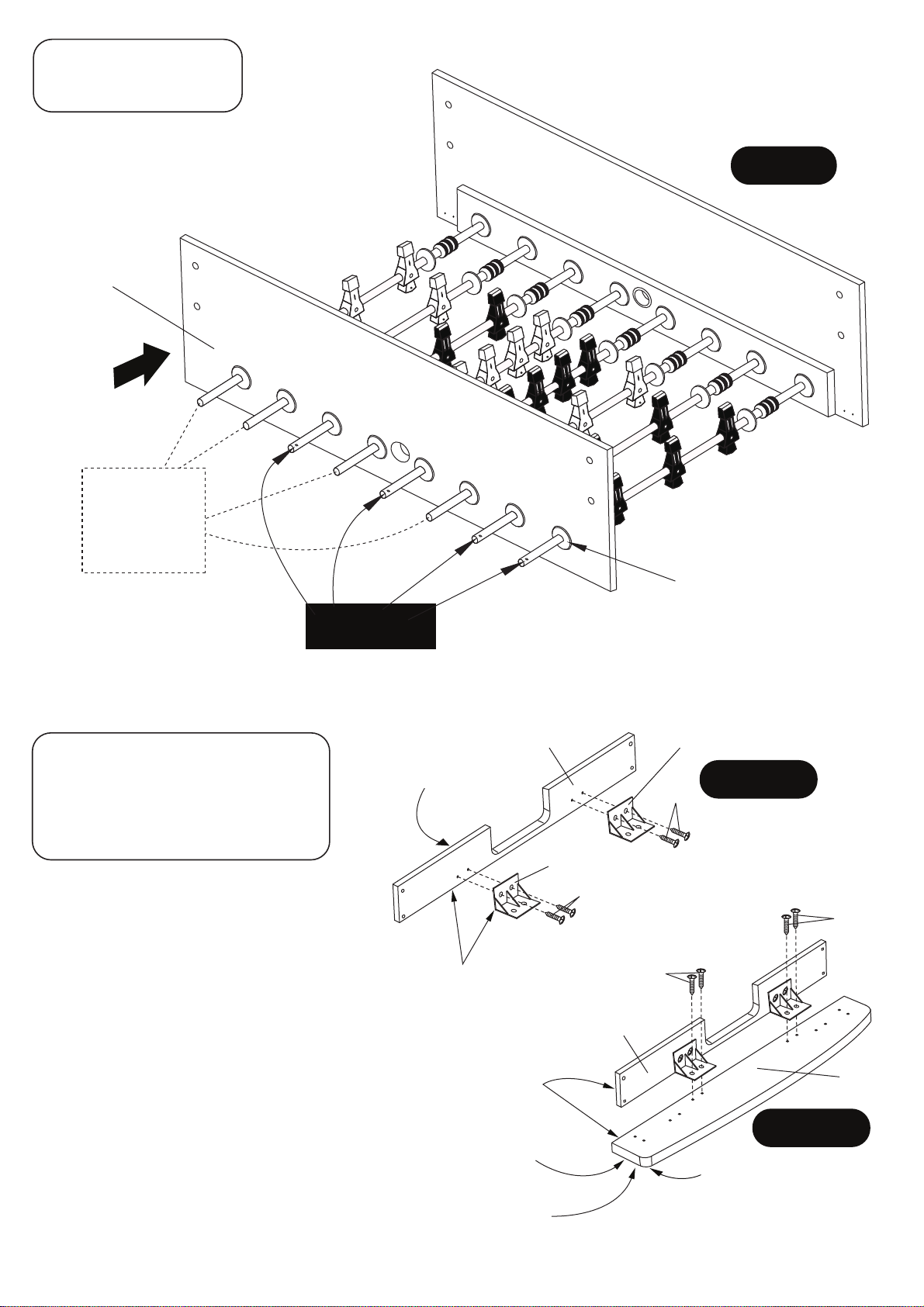
PARTS REQUIRED:
1 pc - P1 Side Apron
STEP 2:
Once your are sure you have the rods set
correctly, slide the other P1 Side Apron on
the rods as shown in FIGURE 2.
P1
R5
R4
R2
R4, R5 and R6
Hole/Handle
goes on the
other end of
these rods
R6
R1, R2 and R3
Hole/Handle End
R3
R5
R1
R2
FIGURE 2
C1 Rod Bushing
Note: C1 Rod Bushings
are already attached
onto P1 Side Apron
PARTS REQUIRED:
16 pcs - H4 Phillips Round Head Screw
2 pcs - P5 End Top Rail
2 pcs - P6 Goal End Board
4 pcs - P18 Plastic Bracket
STEP 3:
Place two P18 Plastic Brackets onto each inside
end of P6 Goal End Board as shown and attach
using the pre-drilled pilot holes with H4 Screws
as shown in FIGURE 3A.
Tighten, but do not strip out H4 screws.
NOTE: Be sure bottom edge of P18 Plastic
Brackets is flush with bottom edge of board.
Next, attach this assembly to P5 End Top Rail
using pre-drilled pilot holes with H4 Screws as
shown in FIGURE 3B.
Tighten, but do not strip out H4 screws.
NOTE: Be sure bottom edge of P6 Goal End
Board is flush with bottom edge of P5 Top Rail.
Repeat procedure for second assembly.
All Rights Reserved.
©
2012 Escalade Sports
P6
White laminate
this side
Edge must be
flush for correct
assembly
Edge must be
flush for correct
assembly
Black laminate
on bottom side
NOTE: See STEP 4 to look at
correct assembly P5 and P6.
7
P18
FIGURE 3A
H4
P18
H4
H4
H4
P6
P5
FIGURE 3B
Round Corner
this position
For Customer Service Call 1-888-996-2729

PARTS REQUIRED:
8 pcs - H3 Phillips Flat Head Screw
STEP 4:
Attach P5/P6 previous assemblies STEP 3 to P1 Side Apron using pre-drilled pilot holes with H3 Screws as
shown in FIGURE 4.
Tighten, but do not strip out H3 screws.
IMPORTANT NOTE:
Be sure to keep this assembly
square during P5/P6 assembly.
H3
H3
H3
P5/P6
Assembly
H3
P1
FIGURE 4
PARTS REQUIRED:
16 pcs - H4 Phillips Round Head Screw
4 pcs - P18 Plastic Bracket
STEP 5:
Install one piece P18 Plastic Bracket
into each inside corner of P1 Side Apron
using pre-drilled pilot holes and H4
screws as per FIGURE 5 and DETAIL A.
Tighten, but do not strip out H4 screws.
P1
H3
H4
H4
DETAIL A
H3
P5/P6
Assembly
P18
All Rights Reserved.
©
2012 Escalade Sports
FIGURE 5
8
For Customer Service Call 1-888-996-2729

PARTS REQUIRED:
2 pcs - P12 Playfield Trim
STEP 6:
Peel the protective coating off P12 Playfield Trims, then peel the adhesive strip protective film off the underside
of P12 Playfield Trims. Turn them over and carefully place them along P1 Side Aprons as shown in DETAIL B
and FIGURE 6.
FIGURE 6
P12
P12
P1
Peel and Turn Over
DETAIL B
NOTE: Adhesive
strip this side.
PARTS REQUIRED:
18 pcs - H5 Phillips Washer
Head Screw
1 pc - P4 Playfield
STEP 7:
Place P4 Playfield with graphics
facing down onto the main cabinet.
Align P4 Playfield holes with P12
Playfield Trims holes and attach
using H5 Screws as shown in
FIGURE 7.
Tighten, but
Screws.
IMPORTANT NOTE:
P4 Playfield must be evenly
spaced on top of both ends
of P6 Goal End Board - at each
end of cabinet assembly.
do not strip out H5
Graphic
facing down
P4
H5
P6
P1 Side Aprons may be slightly
warped. Please keep P1 Side
Aprons pushed in tight against
the P4 Playfield for correct assembly.
All screws must be screwed
STRAIGHT down.
All Rights Reserved.
©
2012 Escalade Sports
FIGURE 7
P6
9
For Customer Service Call 1-888-996-2729
 Loading...