

Atomic AT-1 3CH Transmitter Instruction Manual
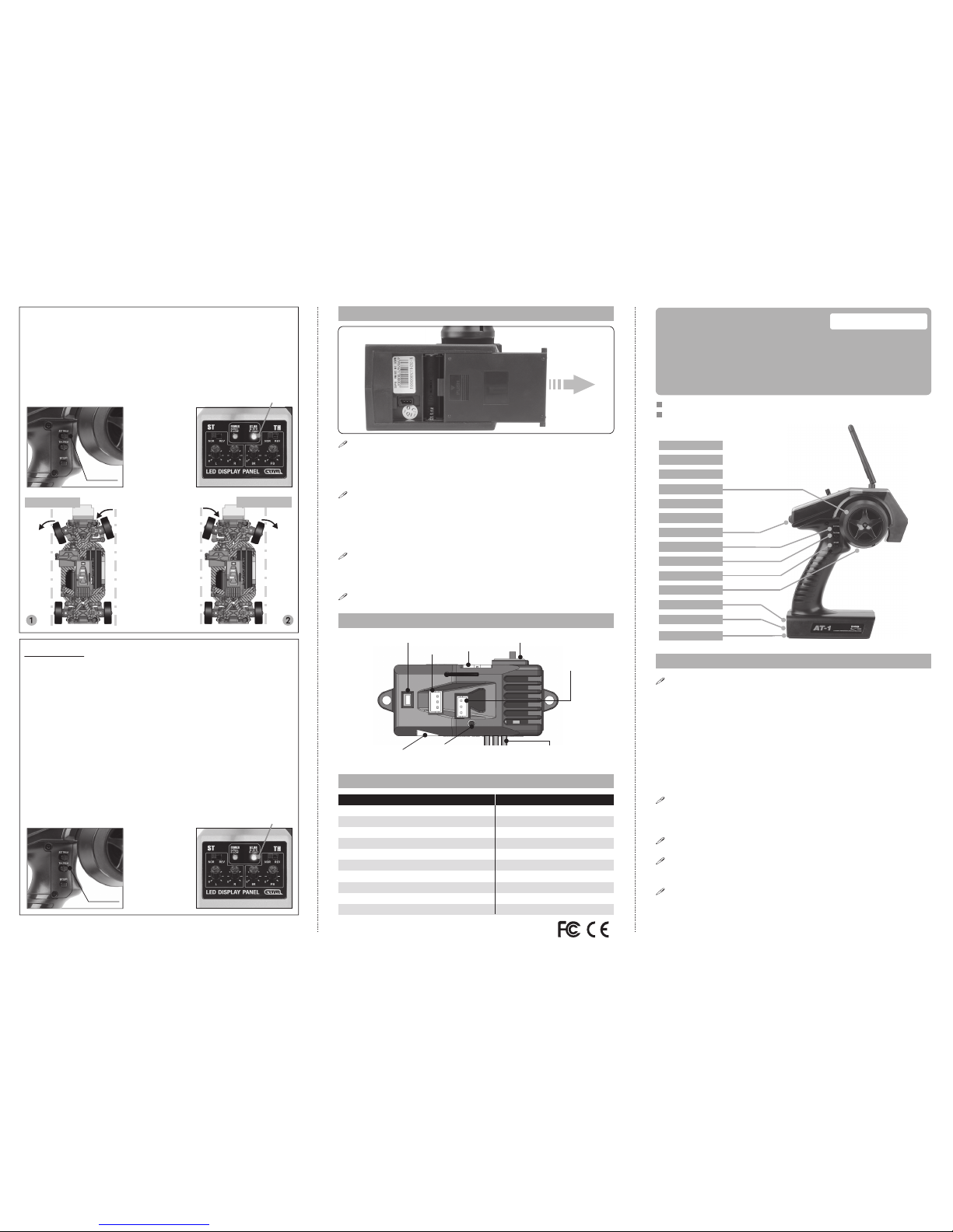
Steering Wheel
AUX Channel
3-Channel 2.4G Radio Control System
INSTRUCTION MANUAL
2.4G FHSS Technology
CAUTION
Thank you for purchasing our R/C system.
Before using, read this manual carefully.
To use your R/C with your models correctly and safely, read this
manual carefully and keep it in a safe place for future reference.
Before using the transmitter, make sure the transmitter batteries are
well loaded. The voltage of transmitter batteries is never lower than
8.6V. And please check and confirm that the servos are all well and
properly connected.
Keep the radio system away from moist, high temperature and strong
vibration. Do not clean the product with solvent.
Avoid the antenna come in contact with anything else when power
switch is turned on. Do not leave this product and its accessories
within the reach of small children.
Please use this product according to your local relevant law or
regulation, we are not responsible for any accident or damages to your
product.
Warning:
1. This product is only equipped for radio controlled models;
2. The usage of this product should be approved by local relevant law
or regulations;
3. We will not be responsible for any damages caused by unauthorized
modification, adjustment or replacement of parts of this product;
4. The manual may be altered without prior notice. Please contact us if you
have any corrections or clarifications that should be made in the manual.
Steering Trim
Throttle Trim
ST. Dual Rate
Throttle Trigger
Power Switch
Charging Jack
Battery Box
Trim Operation and Maximum Travel.
Changing the trim can effect the overall settings, when adjustments are
made with the trims, please recheck your installation for maximum servo
travel.
When Trim movement goes to extremes
That means if you make a lot of trim movement to get a servo to the
neutral position, please reposition the servo horn or servo saver on the
servo and inspect your linkage installation.
Caution:
When find
the direction
is wrong,
change to
relevant REV
button.
1. When adjusting
the TRIM button,
the "ST.DR" LED
flashes in GREEN.
2. When in the
neutral position,
the LED appears
in RED.
3. When steering hits
maximum angle,
LED flashes in RED
momentarily then
return to its
normal state.
TURN LEFT
TURN RIGHT
FLASH
Throttle Trim
Throttle neutral adjustments can be made by moving the throttle trim to
the left or the right.
Racer Tip
When using a electronic speed control, please set the throttle trim to
neutral and make adjustments to the speed control. On a gas powered
model, set the trim to neutral and adjust the linkage to the point where
carburetor is fully closed in accordance with the engine instruction
manual.
Trim Operation and Travel
Trim adjustments will effect the overall servo travel, so please check the
(backward) movement after the adjustment.
When trim movement goes to extremes
That means if you make a lot of the trim movement to get the servo to the
neutral position, please recenter the servo horn closer to the neutral
position and inspect your throttle linkage.
LOCK
RECEIVER CONNECTION DIAGRAM
TECHNOLOGY DATA
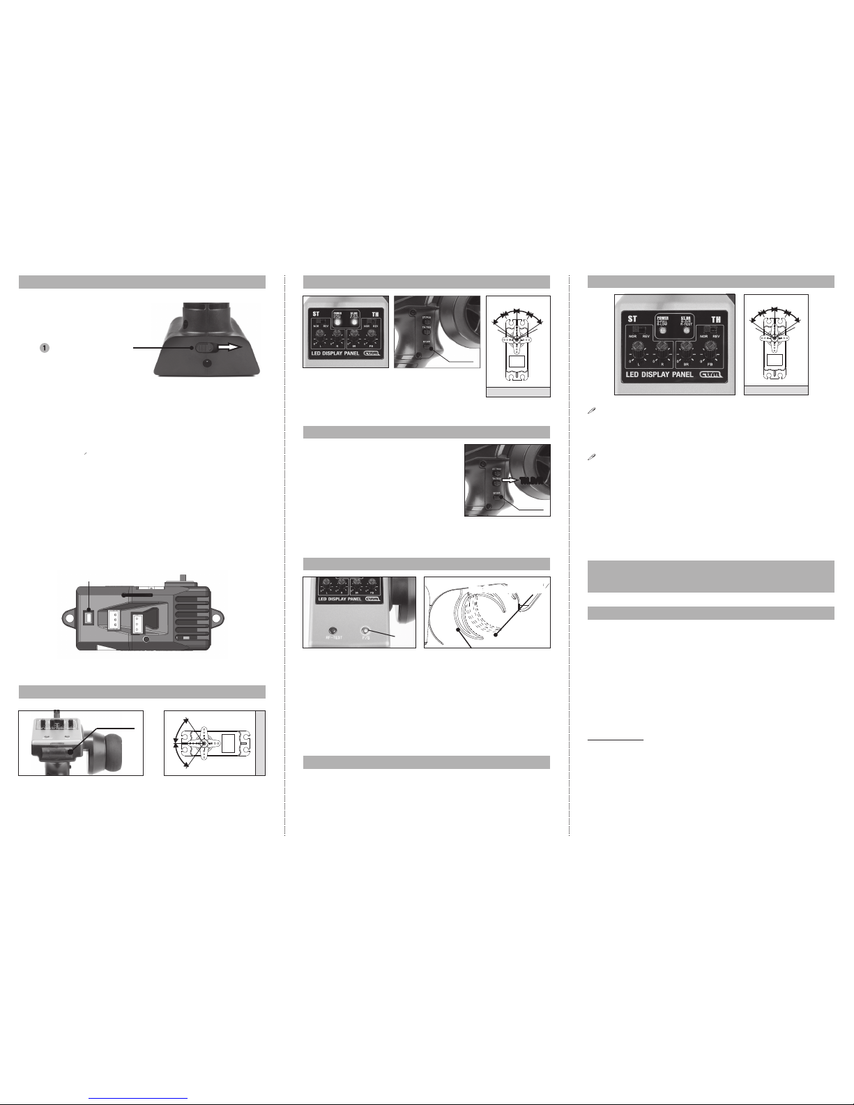
Battery Replacement
1) Slice the battery cover out of the transmitter in the direction of the
arrow. 2) Remove drained batteries. 3) Load the new AA size
batteries. Pay very close attention to the polarity marking and reinsert
accordingly. 4) Slide the battery cover back into the case.
Caution
Always ensure reinserted batteries are in the correct polarity order. If
batteries loaded incorrectly may cause damage to the transmitter.
When the transmitter is not in use, always remember to remove the
batteries. If the batteries do happen to leak, clean the batteries case
and contacts thoroughly. Make sure the contacts are free of corrosion.
Battery Disposal
Some countries require special handling of used batteries, please
contact the agencies responsible for recycling hazardous wastes in
your local area.
Battery low voltage alarm indicator.
ST.TRIM
TH.TRIM
BIND
PROGRAMMING
(ESC)
POWER SWITCHPOWER IN
(7.4V)
SETUP
SWITCH (TH)
WIRES ESCSERVO CH2
SERVO CH3
FLASH
TRANSMITTER RECEIVER
Channel: 3 Channel: 3
Rosolution: 4096 Frequency: 2.4G ISM Frequency
Frequency: 2.4GHz ISM Frequency Range Spread Spectrum Mode: FHSS
Modulation: GFSK Power: 4.5-7.4V, <30mA
Spread Spectrum Mode: FHSS
Number of Frequency Channel: 20
Hopping Rate: 240 Jump/s
Output Power: <=20dbm
Working Current: <=150mA
Working Voltage: 1.2V*4NiCad / NiMH
ATOMIC AT-1 3CH Transmitter
2.4G BINGING AND REDUCING POWER
STEERING DUAL RATES CHOICE
SERVO
Gas Car Brake PositionGas Car Brake Position
LEFT
BACK
RIGHT
FWD
RESET
FAIL SAFE SETUP
LOCK
Power switch (Turn On)
TRIM ADJUSTMENT
EPA ADJUSTMENT
Function
Use this when performing left and right steering angle adjustments,
throttle high/ brake operation amount adjustment during linkage. End
point adjustment (EPA) adjusting value range: 0-100%
Setting
1. Steering (left side) adjustment
Adjusting the potentiometer “L”, in “0” position shown the min. value 0%
2. Steering (Right side) adjustment
Adjusting the potentiometer “R”, in “0” position shown the min. value 0%
3. Throttle (forward) adjustment
Adjusting the potentiometer “MAX”, in “0” position shown the min. value
0%
4. Throttle (brake) adjustment
Adjusting the potentiometer “BR”, in “0” position shown the min. value
0%
Caution:
When adjusting this function, make sure the direction is in agreement
with the RC car or boat direction, you can adjust by the REV button.
1. Reducing output power setting
1. Hold the RF-TEST button until the "ST.DR" light turns to RED.
Meanwhile the output power of transmitter reduce to lower mode
18dbm, which then reduces power consumption.
2. When pressing the RF-TEST button again, the "ST.DR" light
deactivate, and output power becomes normal 20dbm which
subsequently can control more range.
Function
Using this function to adjust servo travel.
The default is 100%. When pressing D/R, the front
light flashes, and the value quickly switch to 70%.
Function
All the setting in the system will be reset to the
default values with this reset function.
1. Press the ST.D/R and push the TH.TRIM
button forward together, then turn on the
Transmitter at the same time, the POWER
and ST.DR lights will blink, mean it’s
resetting.
2. To ensure this function work properly,
Transmitter has to be switch off and then
back on again.
Function
This F/S Function is to protect your RC car/boat, when the signal become
weak or lost.
Setup precedure:
1. Make sure the Receiver power is enough for this operation.
2. Put trigger in brake position (above show). Press and hold the F/S button
until “ST.DR” become red.
3. Then release F/S button, the setup now finished.
Lock Function
When pressing “RF-TEST” and “F/S” button simultaneously, the front light
become red, mean it’s locked. There should be no reaction from pressing
ST.TRIM, TH.TRIM or D/R buttons now, mean it’s working correctly. Press
both “RF-TEST” and “F/S” button again to unlocked.
2. The Binding processing
Turn on the transmitter, then connect the power of receiver, keep the
receiver "BIND" button on hold until the light switch to GREEN which
means the binding is successful. After that, it's unnecessary to bind
again.
Caution: Ensure the Receiver and Transmitter is one meter away,
approximately 10 meters with no similar devices within range.
If the light keep flashing, this indicate binding failure, please go back
and try again from the beginning.
When pressing the “AUX” channel, the servo move clockwise, pressing
again will change to anti-clockwise.
AUX CHANNEL FUNCTION (CH3)
SERVO
100% 100%
0
0
20%
100%
120%
20%
100%
120%
120%
EP Car Brake Position
F/S
Please start the motor or the engine while making the adjustment of these
settings.
1. Connect the receiver, servos, and other components and then turn on
the power switches of the transmitter and receiver.
2. Be sure the Steering trim and Throttle trim on the transmitter are at
their neutral position.
3. Before turning on the transmitter, please make sure the transmitter
antenna is completely extended. Turn on the transmitter before turning
on the receiver, while turn off the receiver before turning off the
transmitter.
Steering Trim
Steering neutral adjustments can be made by moving the steering trim knob
to the left or the right.
Racers Tip
Always check and be sure the servo is at its neutral position before
installing a servo. Adjust the servo horn hole position and linkage so that
both are parallel. When a servo saver is used, place it as closer to center
position as possible. Be sure the steering trim on the transmitter is at its
neutral position.
SERVO
LEFT
BACK
RIGHT
FWD
0
20%
100%
120%
20%
100%
120%
AUX Channel
ST.D/R
ST.D/R
TH.D/RTH.D/R
BIND
 Loading...