

Atomic AmpliFire User Manual
USER MANUAL
V 1.0


3
TABLE OF CONTENTS
INTRODUCTION ..........................4
CONNECTION DIAGRAM. .. . . .. . . .. . . .. . . . 5
CONNECTORS .. . . .. . . .. . . .. . . .. . . .. . . .. . . . 6-7
EFFECTS & SIGNAL CHAIN ...............8
PRE EFFECTS. .. . . .. . . .. . . .. . . .. . . .. . . .. . . . 9
AMPS ......................................10
FX-LOOP. . .. . . .. . . .. . . .. . . .. . . .. . . .. . . .. . . . 11
POST EFFECTS. . . .. . . .. . . .. . . .. . . .. . . .. . . . 12
CABINET MODELING. .. . . .. . . .. . . .. . . .. . . . 12-13
SELECTING PRESETS .. . . .. . . .. . . .. . . .. . . . 13
QUICK EDIT - TWEAK KNOBS. . . .. . . .. . . . 13
DEEP EDIT - PRESET PARAMETERS . . . . 14
MENU DIAGRAM . .. . . .. . . .. . . .. . . .. . . .. . . . 15
SAVING PRESETS .. . . .. . . .. . . .. . . .. . . .. . . . 16
DEFAULT PRESET ON POWER-UP ......17
DISCARD EDIT? CONFIRM. . . .. . . .. . . .. . . . 17
PARAMETER SETTINGS ..................18-31
GLOBAL SETTINGS .......................33-36
FOOTSWITCHES ..........................36
FOOTSWITCH MODES. . . .. . . .. . . .. . . .. . . . 36-37
PROGRAMMING FOOTSWITCHES .......37-38
TUNER .. . . .. . . .. . . .. . . .. . . .. . . .. . . .. . . .. . . . 38
CLIP WARNING. . . .. . . .. . . .. . . .. . . .. . . .. . . . 38
EXPRESSION PEDALS . . . .. . . .. . . .. . . .. . . . 39-41
MIDI. . . .. . . .. . . .. . . .. . . .. . . .. . . .. . . .. . . .. . . . 42-43

4
INTRODUCTION
Thank you for purchasing AmpliFire, a world-class amp tone and multi-effects pedal.
A powerful and portable device, it is small enough to fit in the front pocket of a
gig bag yet potent enough to please even the most discriminating tube amp
and effects aficionados.
We designed Amplifire as an instrument that we, as guitar players, wanted for
ourselves. This meant it had to sound/feel authentic and amazing while being
easy to use, transport and be road rugged.
Amplifire is equally capable of being a complete rig replacement or part of a
larger pedal board and/or outboard processing rig.
HERE ARE SOME HIGHLIGHTS:
• All new, state-of-the-art amp modeling based on Studio Devil’s highly
acclaimed and patented technology
• Blazing dual-DSP powered hardware allowing for complex and
detailed algorithms
• Stereo 1024 point cabinet impulses with ability to upload 3rd party IRs
• Robust effects selection including drive, modulation, delay, reverb, compression,
eq, gate, etc.
• Dedicated, physical amp control knobs for intuitive tone adjustments
• Pristine studio quality audio quality and ultra low noise floor
• Versatile i/o options including ¼” Hi Z input with proprietary processing, separate
stereo ¼” and XLR outputs and user programmable effects loop
• 3 fully configurable and rugged foot switches
• Robust external control of presets parameters via midi and foot switch jacks
• Easy to use as a pedal or desktop device
• PC/Mac editor
• 128 programmable presets
• Field upgradeable firmware
• And much more!
Enjoy!
5
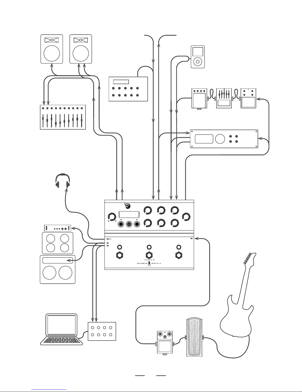
CONNECTION DIAGRAM
ampli fire
BASS MIDS
TREBLE
SAVE
PRESENCE
LEVEL
PRESET
VALUE
GAIN MASTER
(PUSH TO EDIT)
IN
R
L
TO OTHER
MIDI EFFECTS PROCESSORS
FROM OTHER
MIDI CONTROLLERS
MIDI FOOT
CONTROLLER
FULL RANGE
LOUDSPEAKER
SYSTEM / P.A.
MP3/MEDIA PLAYER
EFFECTS LOOPAUX OUTPUTS
MAIN
OUTS
MIDI
SEND
RETURNS
MIDI OUT
MIDI IN
INSTRUMENT
(
GUITAR OR BASS
)
POWERED AMPS
HEADPHONES
MIXING CONSOLE
OTHER EFFECTS PEDALS
(
WAH, OVERDRIVE, ETC.
)
COMPUTER RECORDING INTERFACE
EFFECTS PEDAL CHAIN
EFFECTS PROCESSOR

6
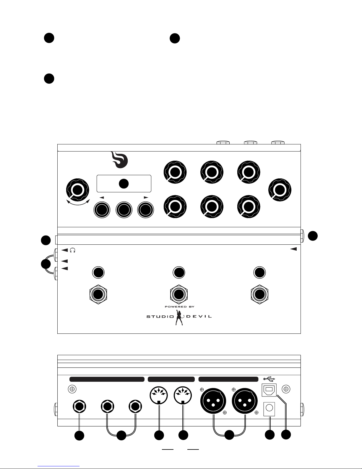
CONNECTORS
1. DATA ENTRY ENCODER – used to
select and edit user presets. Turn to
select a preset or change a parameter
value. Push (click) to select menus for
editing presets.
2. BACK BUTTON – used to decrease
preset or to go to previous item in
edit menus.
3. SAVE BUTTON WITH LED – used to
save presets. Press once to select
destination and new preset name.
Press again to commit the save. Press
and HOLD for TUNER function. Built-in
LED blinks when a preset has been
edited but not saved as a warning to
save your edits.
4. NEXT BUTTON – used to increase
preset or to go to next item in edit
menus.
5. LCD SCREEN – displays currently
active preset or edited data name and
value.
6. GAIN KNOB – adjusts the gain control
of the preamp of the virtual guitar
amplifier model.
7. MASTER KNOB – adjusts the master
volume control of the virtual guitar
amplifier model.
8. PRESENCE KNOB – adjusts the
presence control of the simulated
power amp section of the virtual guitar
amplifier model.
9. BASS KNOB – adjusts the bass
equalization control of the tone stack
in the virtual guitar amplifier model.
10. MIDS KNOB – adjusts the mids
equalization control of the tone stack
in the virtual guitar amplifier model.
11. TREBLE KNOB – adjusts the treble
equalization control of the tone stack
in the virtual guitar amplifier model.
12. LEVEL KNOB – sets the output
level of all outputs simultaneously
(MAIN outputs, AUX outputs, and
HEADPHONES level). This is like an
analog output level control.
13. FOOTSWITCH – fully programmable
footswitch for changing presets,
enabling individual effects, or selecting
tap tempo.
14. DUAL-COLOR LED – indicates the
state of the programmable footswitch.
In preset mode, lights up in RED or
AMBER to indicate preset A or preset
B. In effect enable mode, lights up RED
when effect is active. Blinks at repeat
rate for TAP TEMPO function.
15. GUITAR INPUT – Hi-Z input for
connecting an electric guitar with a
1/4” phone jack.
16. MAIN OUTPUTS – TRS balanced
(or unbalanced) 1/4” output jacks
for connecting to amplifiers, mixers,
computer interfaces, or input channels
of other audio devices.
17. HEADPHONE JACK – 1/8” mini jack for
connecting to headphones. REMEMBER
TO USE CAUTION WITH HEADPHONES.
EXCESSIVE LOUDNESS IS HARMFUL TO YOUR
HEARING AND HEALTH.
18. FX LOOP SEND JACK – 1/4” mono
output jack for connecting to the input
of an external effects unit.
19. FX LOOP RETURN / AUX IN JACKS
– stereo 1/4” jacks for connecting
to either the outputs of an external
effects unit or to an auxiliary music
player. In FX LOOP mode, these act as
a switchable external effect between
the amp modeling and the stereo post
effects section. In AUX IN mode, these
act as an auxiliary audio input which
can be mixed with your processed
guitar output (for playing along with
backing tracks, etc.).
20. MIDI OUT JACK – 5-pin DIN connector
for connecting to the MIDI input of
an external effects processor. Allows
synchronizing program changes to an
external processor which may be used
in the effects loop. Also performs an
optional MIDI THRU function to merge
incoming MIDI data from the
MIDI IN jack.
22. MIDI IN JACK – 5-pin DIN connector
for connecting to the MIDI output of
a MIDI controller or MIDI footswitch.
Allows for changing presets via
program changes and enabling
individual effects via continuous
controllers.
21
20
19
18
17
16
15
141
2
3
4
5
6
7
8
9
10
11
12
13
7
AUX OUTPUT XLR JACKS –
Balanced XLR output jacks for
connecting to external mixer
or professional direct recording
equipment.
23. DC POWER JACK – for connecting
to a 9 or 12 volt power supply
(DC or AC, either polarity), 1A
minimum. Accepts a standard
2.1mm coaxial plug (either
polarity).
24. USB CONNECTOR – for
connecting to a host PC. Allows
easier editing of presets and
uploading custom user cabinet
impulse data and firmware via
host editing software.
CONNECTORS CONTINUED...
ampli fire
SEND
EFFECTS LOOP / AUX INPUT
RETURN / AUX IN
LEFT (MONO)
MIDI AUX OUTPUT
OUT IN
RIGHT
LEFT
9V (1A)
RIGHT
BASS MIDS
TREBLE
SAVE
PRESENCE
LEVEL
PRESET
VALUE
GAIN MASTER
(PUSH TO EDIT)
IN
R
L
SEND
EFFECTS LOOP / AUX INPUT
RETURN / AUX IN
LEFT (MONO)
MIDI AUX OUTPUT
OUT IN
RIGHT
LEFT
9V (1A)
RIGHT
24
24
23
23
22
22
21
20
19
18
17
16
15
14 14 14
1
2 3
4
5
6 7 8
9
10 11
12
13 13 13

8
EFFECTS AND SIGNAL CHAIN
Amplifire consists of a world-class amp modeling engine and studio quality effects
developed by Studio Devil. They are arranged into the following signal chain groups:
Amplifire is capable of running all of these effects:
NOISE GATE
COMPRESSOR
PRE-FILTER
WAH
VOLUME
DISTORTION / OVERDRIVE/ FUZZ
PARAMETRIC EQ / PROGRAMMABLE FILTER
GRAPHIC EQ
TREMOLO / PANNER
CHORUS
FLANGER
PHASER
ECHO MODELER / PINGPONG DELAY
REVERB
You can choose to place most of these effects into either the PRE-EFFECTS
SECTION, or the POST-EFFECTS section, to allow versatility in pre or post
processing of your amplifier tone.
Think of the PRE-EFFECTS section like the pedals that run into your amp, and the
POST-EFFECTS section as any stereo studio effects you would place onto your
amp after it is mic’d up (either on a live mixing board, or in a recording studio).
All signals before the FX LOOP are mono, and all signals after the FX LOOP are
stereo. So, any stereo effects assigned to the PRE-EFFECTS section will operate in
MONO mode.
PRE-EFFECTS AMP MODEL FX LOOP POST-EFFECTS CABINET MODEL

9
PRE-EFFECTS
The PRE-EFFECTS section allows you to apply any standard MONO effects
processing that would occur BEFORE the guitar amp, such as pedals or other effects
that would be inserted before going into the input of your amp.
The PRE-EFFECTS include:
• The GATE effect provides a programmable NOISE GATE. The NOISE GATE has
global parameter settings, so that you don’t need to change all your presets if
you change your guitar. NOISE GATE enable is programmed per preset, so that
you can shut it off for particular presets, and leave it on for others. These options
can be set in the GATE effect menu.
• The VOLUME effect models a VOLUME pedal control. The VOLUME options can
be set in the VOLUME effect menu. It can be repositioned to three locations:
the PRE-EFFECTS section (as shown), just after the AMP modeling section (just
before the LOOP SEND), or POST-EFFECTS section for maximum flexibility.
• The WAH effect models a WAH-WAH effects pedal. The WAH-WAH is fully
customizable and the options are set in the WAH-WAH effect menu.
• The COMP effect models a compressor module for controlling the dynamics of
your guitar input. The COMPRESSOR options can be set in the COMPRESSOR
effect menu.
• The BOOST effect models classic stomp box distortion effects and can be
repositioned to different locations in the PRE-EFFECTs chain. It is typically
placed before the MODULATION and EQ, but it can be repositioned between
MODULATION AND EQ or after MODULATION and EQ. These options can be set
in the BOOST effect menu.
• The EQ block is made up of the GRAPHIC EQ and three (3) PARAMETRIC EQ
effect modules, each of which can be set to the PRE-EFFECTS section or POSTEFFECTS section. These options can be set in the GRAPHICEQ, PARAMETRIC 1,
PARAMETRIC 2, and PARAMETRIC 3 effect menus.
• The EFFECT block can be assigned to either the PRE-EFFECTS section or POST-
EFFECTS section. You can choose from world-class classic CHORUS, FLANGER,
PHASER, or TREMOLO effects. These options can be set in the EFFECT menu.
• The ECHO effect can be assigned to either the PRE-EFFECTS section or POST-
EFFECTS section to get the different effects of feeding an echo into an amp or
processing echoes after the amp tone. These options can be set in the ECHO
effect menu.
GATE VOLUME WAH COMP BOOST EQ EFFECT ECHO

10
AMPS
At the heart of AmpliFire is Studio Devil’s patented, world-class amp modeling.
It convincingly captures the sound, feel and nuances of the great guitar amps
of all-time.
From the start, AmpliFire provides you with 10 amps that cover nearly all the sonic
territory from Jazz to Djent. They are:
US Clean: Based on the 2 speaker combo that set the standard for clean, loud,
guitar amps spanning a wide variety of styles.
D Luxe: Based on a medium powered, American, single 12” workhorse classic
known for its sna ppy and crystalline tones and coveted by country, blues and rock
players.
‘59 B Man: Based on the amp that inspired many of the amps that would follow
it, this legend started as a bass amp and is known for its diverse tones and touch
sensitive dynamics.
Top Boost: Based on a British classic, this “Class A” 2x12 is known best for its
chime, jangle and it’s beautiful, unique voicing whether played clean, dirty or in
between.
Plexi: Based on the British amp with a reputation for being the definitive Rock tone
machine, this amp can be sweet, crunchy or mean with its mid focused punchy
sound.
Brit 800: Based on the early 80s British 100w head that helped define the Heavy
Metal sound, this beast can blow the roof off but cleans up surprisingly well. Put
an overdrive pedal in front of it and you’ve got “the sound”.
Hot Brit: An Amplifire original model, this amp is inspired by the great British rock
amps but has a tighter low end and more gain on tap so a drive pedal in front as
necessary (unless you want over the top).
Recto: Based on the amp that defined much of the 90s’ heavy sounds, this amp
has tons of gain and compression on tap, sounds great with scooped mids and has
a powerful bottom end.
5051: Based on the original signature amp of one of the most influential guitarists
of all time, this amp is a gain machine that has become a Metal standard with its
focused bottom end and touch sensitive response.
Kornfield: Based on a very popular boutique model, this amp puts its own
aggressive but responsive and nuanced spin on the Brit sound.
This, however, is not where it ends. AmpliFire is a user upgradable platform and
we’ll be issuing free firmware upgrades to add new amps. We’re looking forward to
hearing what our customers would like to see come next. Check back often as there’s
a good chance that this list is already no longer up-to-date.

11
EFFECTS LOOP (FX-LOOP)
The EFFECTS LOOP allows you to place an external effect or processor or pedal into
the Amplifire signal routing chain.
The EFFECTS LOOP is positioned between the AMP MODEL and the POST-EFFECTS
section. The EFFECTS LOOP has a MONO SEND and a STEREO RETURN. All
processing before the EFFECTS LOOP is MONO. All processing after the EFFECTS
LOOP is STEREO.
Connect the MONO SEND to your external effect processor input, and connect the
outputs of your external effect processor to the Amplifire STEREO RETURN jacks. If
your external effect processor has a MONO output only, you may connect it to either
of the STEREO RETURN jacks. (When only one return jack is connected, Amplifire
will automatically split the return signal into dual-MONO mode from either
return jack.)
The EFFECTS LOOP is switchable so you can switch the inserted effect on or off.
You can do this by assigning the EFFECTS LOOP control to a FOOTSWITCH (see
FOOTSWITCH section below). You can also program each preset to have the EFFECTS
LOOP on or off, so that some presets could use the loop effect while others don’t.
If you connect nothing to the EFFECTS LOOP STEREO RETURN jacks, the EFFECTS
LOOP is always off. In this configuration, you may use the SEND jack as an alternate
amp modeling direct MONO output.
The EFFECTS LOOP can be configured as MUTE SEND or MUTE RETURN (spillover).
In MUTE SEND mode, turning off the effects loop only mutes the loop send, allowing
any remaining delay or reverb tails in the loop to properly decay (spillover). In MUTE
RETURN mode, the effects loop acts like a traditional loop, immediately muting the
returns and cutting off the loop right away.
The EFFECTS LOOP can be configured as an AUX INPUT mode (see GLOBAL
SETTINGS sections below). This mode allows you to connect a music player or
backing tracks which are mixed (unaffected) with your main outputs.
If you have the AUX INPUT mode selected, then Amplifire will disable the EFFECTS
LOOP, routing the output of the AMP MODEL effects block directly to the POST-
EFFECTS section. Amplifire will also mix the RETURN JACKS with the MAIN and AUX
outputs, to allow full-range blending of the aux input with your playing.
The EFFECTS LOOP can also be configured as EXPRESSION PEDAL mode, allowing
you to use expression pedals (with a special adapter cable, available separately) to
control effect parameters in real-time. (See EXPRESSION PEDALS section.)

12
POST-EFFECTS
The POST-EFFECTS section allows you to apply any standard STEREO effects
processing that would occur AFTER the guitar amp, such as studio processing or
other effects that would be applied after your amp.
The POST-EFFECTS include:
• The EQ section is made up of the GRAPHIC EQ and three (3) PARAMETRIC EQ
effect modules, each of which can be set to the PRE-EFFECTS section or POSTEFFECTS section. In the POST-EFFECTS section, these effects operate in stereo.
These options can be set in the GRAPHICEQ, PARAMETRIC 1, PARAMETRIC 2,
and PARAMETRIC 3 effect menus.
• The EFFECT block can be assigned to either the PRE-EFFECTS section or POST-
EFFECTS section. You can choose from world-class classic CHORUS, FLANGER,
PHASER, or TREMOLO effects. In the POST-EFFECTS section, these effects
operate in stereo. These options can be set in the EFFECT menu.
• The ECHO effect can be assigned to either the PRE-EFFECTS section or POST-
EFFECTS section to get the different effects of feeding an echo into an amp or
processing echoes after the amp tone. In the POST-EFFECTS section, this effect
operates in stereo. These options can be set in the ECHO effect menu.
• The REVERB effect is the last effect in the POST-EFFECTS section to apply
simulated room acoustics and reverberation to the final tone. This effect is
stereo. These options can be set in the REVERB effect menu.
• The VOLUME effect models a VOLUME pedal control. The VOLUME options can
be set in the VOLUME effect menu. It can be repositioned to three locations:
the PRE-EFFECTS section, just after the AMP modeling section (just before the
LOOP SEND), or POST-EFFECTS section (as shown) for maximum flexibility.
CABINET MODELING
The CABINET section is where Amplifire applies Impulse Response (IR) modeling
technology and filtering to simulate the sound of microphones and guitar loudspeaker
cabinets. Each of the amp models in Amplifire contain a built-in IR cabinet. Amplifire
also supports user customizable IR cabinets which you can upload to Amplifire via
USB.
• The CABINET modeler can be configured to use any cabinet from the list of amp
models, or any one of the user-defined cabinets.
• The CABINET modeler lets you tweak the cab models with filters specially
designed for adjusting microphone and loudspeaker cabinet tones.
• The CABINET modeler can be enabled or disabled on either set of outputs
independently (MAIN / AUX), allowing you to use full range systems AND other
real guitar cabinets simultaneously.
• The CABINET modeler is always enabled on the headphones output (although
you can choose to disable the cabinet modeling on all outputs for three separate
full range outputs).
EQ EFFECT ECHO REVERB VOLUME

13
CABINET MODELING CONTINUED...
MATCHED CABINETS
Each amp model in Amplifire has its own built in cabinet IR model. These cabinets
are “matched” to the amp model, meaning that they model the type of cabinet that
is typically used with that particular type of amp model. Without any programming
or cabinet selection, you get the “right” sound by default by leaving the MATCHED
cabinet option set. This way, when you change an AMP MODEL, you automatically
get the typical cabinet for that amp.
Amplifire allows you customize your tone and swap out these “matched” cabinet
models for those that are from the other amp models. To hear what an amplifier
sounds like with another amp’s cabinet, just select another cabinet from the list in the
CABINET menu.
SELECTING A CABINET
To EDIT THE CABINET OPTIONS from the preset display, click the ENCODER twice:
the first time takes you to the AMP MODEL menu, the second time takes you to the
CABINET menu. Then, turn the encoder to select a new CABINET model or mode.
Press the NEXT and BACK buttons to cycle through some of the other CABINET
modeling options, including filter tweaks.
USER CUSTOM CABINET IRS
Amplifire also supports custom USER CABINETS that you can upload to Amplifire via
USB. To use one of these custom cabinets, just select one of the user cabinet slots
from the end of the list in the CABINET menu. For more information, see the USB
section below.
SELECTING PRESETS
Amplifire stores 128 user programs called presets. You can select the active preset
from this set with the ENCODER knob or the NEXT and BACK buttons. To advance to
the next preset, press NEXT. To backtrack to the previous preset, press BACK. Press
and hold NEXT or BACK to advance quickly through the presets. You can also turn
the ENCODER knob clockwise to go forward or counter-clockwise to go backward.
Amplifire automatically loads the preset as soon as you select it.
QUICK EDIT - TWEAK KNOBS
Amplifire includes six (6) quick tweak knobs to make adjustments just like on a real
amplifier without having to enter edit menus or programming. These six knobs allow
you to adjust GAIN (tube preamp gain), MASTER (tube power amp master volume),
PRESENCE (tube power amp presence control), BASS, MIDS, and TREBLE (tube
preamp tone stack controls).
Just grab and turn one of the knobs to instantly adjust the tone. The display will show
the value while you’re turning the knob to let you know where it is. It also shows you
how it compares to the original preset value using left and right arrows in the display.
The arrows show you which direction to turn to match the knob with the original
preset value. When both arrows are displayed, the knob matches the original preset
value.
Once you edit the preset, the SAVE LED starts blinking, warning you to remember to
save your changes if you want to (see SAVING PRESETS below).

14
DEEP EDIT – PRESET PARAMETERS
Amplifire has many effects modules, and each effects module has several
parameters. Deep editing allows you to customize each of these parameters to
create your own tone and effects setup. Here’s how it works:
• To ENTER EDIT MODE, push down on the ENCODER knob. This takes you to the
first effect menu, AMP MODEL.
• To CHANGE THE PARAMETER VALUE, turn the ENCODER knob right or left to
increase or decrease your selection.
• To ADVANCE TO THE NEXT PARAMETER within an effect menu, press the NEXT
button. This takes you to the next parameter within that same effect.
• To BACK UP TO THE PREVIOUS EFFECT PARAMETER, press the BACK button.
This takes you to the previous parameter within that same effect.
• To ADVANCE TO THE NEXT EFFECT MENU, press down on the ENCODER knob
again. This takes you to the next effect menu.
• To EXIT EDIT MODE, press and hold down either the ENCODER knob or the
BACK button for one second. This will return to the preset display.
The effects MENUS are organized as depicted in the diagram below. Press the
ENCODER knob to go down to the next effect menu, and press the NEXT and BACK
buttons to move right or left across each effect menu’s parameters. At any location,
turn the ENCODER to change the value.
Some tricks about the EDIT MODE:
• WRAP-AROUND: If you are currently at the last parameter item in the
same effect, pressing NEXT will wrap-around and take you to the first
item of the next effect menu.
• FAST BACK: If you are currently at the first parameter of an effect,
pressing BACK will take you back to the first parameter of the previous
effect menu! This is to provide a FAST BACK option for when you want to
quickly advance from a menu far down the list to one closer to the top.
• FAST OPTIONS MENU: The last menu is the OPTIONS menu, which sets
some global parameters. To get there quickly, press and hold the NEXT
button for one second. This takes you to the last menu immediately
without having to press the ENCODER knob several times.
 Loading...