

Page 1
V-850
Atom
Infant
Incubator
OPERATING
MANUAL
ER
ATOM
MEDICAL
CORPORATION
Page 2
It
is
and
familiarize
highly
recommednded
yourself
that
with
you
this
read
Incubator
this
Manual
thoroughly
carefully
by
applying
features
oxygen
so
This
incubators;
sections
supply,
that
Manual
Specifications
1-1
1-2
power
including
you
may
is
V-850
unrelated
V-850
V-850W
to
the
empty
temperature
etc.
intended
inceubatO エ 0 0 IT
before
use
it
with
SC,
V-850
to
your
double-wall
for
model.
CONTENTS
unit
placing
confidence.
use
ヨゴ
incubator
control,
with
MC,
エゴ
TO
つて て に
and
V-850W
operating
humidity
the
unit
four
て に て に て て に て し に
different
MC.
.。...............。
トト
in
Skip
トト
its
control,
actual
unnecessary
トト て て
various
service,
types
・・・・・
of
1
5
[2]
[3]
四
15]
Nomenclature
2-1
2-2
2-3
2-4
Incubator
Operating
4-1
4-2
Manual
Servo
Air
Double-wall
OF
V-850W
Operation
Operation
Humidity
and
Functions
control
control
circulation
effect
incubator
Installation
Instructions
of
of
Control
type
type
system
manual
servo
に
(MC)
(SC)
and
.,..............,............
control
control
に に に に に に に に に に に に に
....................
PE
of
V-850
air
circulation
........................s
unit
unit
トト
トト て トト
incubator
.............
..............
.....
system
ーーー て ーーーーー・
6
10
14
16
18
20
27
38
Page 3
Oxygen
ll
Alarms
Operation
CN
D
Management
Cleaning,
EL
Troubleshooting
LI
Cautions
[I
Supply
Games
of
of
Disinfection
for
Cerro
Other
Incubator
Guide
Safe
Incubator
Mechanisms
in
and
II
vo.
..
Use
Maintenance
Operation
・
43
48
54
60
62
74
.
79
Page 4
(ij;
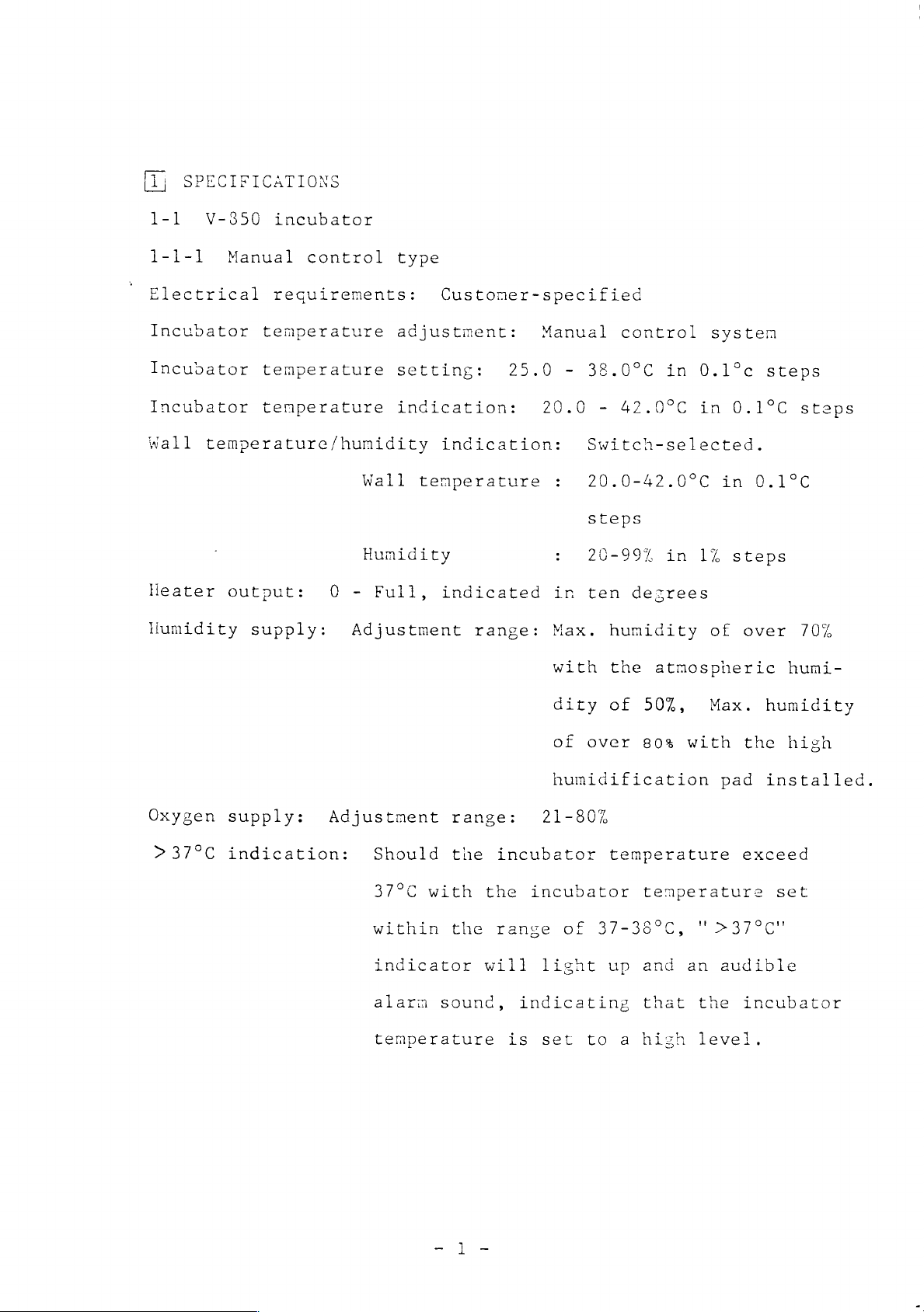
SPECIFICATIONS
1-1
1-1-1
Electrical
Incubator
V-850
Incubator
Incubator
Wall
Heater
Humidity
temperature/humidity
incubator
Manual
requirements:
temperature
temperature
temperature
output:
supply:
control
Wall
Humidity
0 - Full,
Adjustment
type
Custoner-specified
adjustment:
setting:
indication:
indication:
temperature
indicated
range:
Manual
25.0
38.0°C
20.0 - 42.0°C
Switch-selected.
20.0-42.0°C
steps
20-99%
in
ten
Max.
with
control
in
in
desrees
humidity
the
atmospheric
systen
0.1°c
in
0.1°C
in
1%
steps
of
steps
0.1°C
over
steps
70%
humi-
Oxygen
>
37°C
supply:
indication:
Adjustment
Should
37°C
within
indicator
alarm
temperature
range:
the
with
the
sound,
21-80%
incubator
the
incubator
range
will
light
indicating
is
set
dity
of
humidification
of
50%,
over
80%
temperature
temperature
of
37-38°C,
up
and
that
to a high
Max.
with
pad
'>37°C"
an
audible
the
level.
humidity
the
high
installed.
exceed
set
incubator
Page 5

Alarms:
Audible
and
visible
alarms
for
over-temperature,
Alarm
Menory
cisable:
function:
Accessories:
internal
sensor
also
circulation,
and
flash.
The
disabled
is
Should
power
for
will
will
returns.
Cap
(rubber
power
audible
pressed.
failure
temperature
be
be
set
failure.
alarm
for
fifteen minutes
power
supply
or
retained
unnecessary
stopper)
temperature,
Some
for set
be
other
and
items
in
memory,
to
..........
internal
displayed
temperature
when
interrupted
causes,
to
be
so
reset
when
soso
values
is
the
switch
due
the
set
displayed
that
it
power
to
vallue
그
Spares:
F-4
Access
I.D.
High
card
humidification
Humidity
Filler
Air
intake
(Needed
Dust
cover
filter
port
sensor
(for
adjustment
only
element
cover
ュー
pad
wetter
filling
in
water
60Hz
..... 6 eee
.............
.....
ュー
sese
...............
......,.........
reservoir)
ring
for
areas)
60Hz
1
...
...
nom...
29
3
10
1
1
1
Page 6
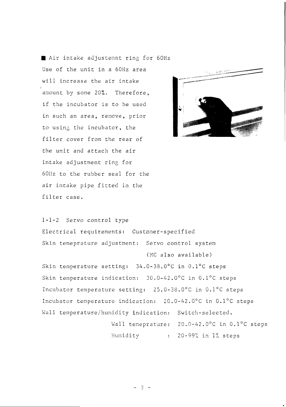
Ш
Use
Air
intake
of
the
adjustemnt
unit
in
a
60Hz
ring
area
for
60Hz
will
amount
if
the
in
such
to
using
filter
the
intake
60llz
air
filter
1-1-2
increase
by
incubator
an
cover
unit
adjustment
to
the
intake
case.
Servo
some
area,
the
and
rubber
pipe
the
air
20%.
is
to
remove,
incubator,
from
attach
control
the
the
ring
seal
fitted
intake
Therefore,
be
used
prior
the
rear
type
air
for
for
in
of
the
the
一
一 一 一
Electrical
Skin
Skin
Skin
temeprature
temperature
temperature
Incubator
Incubator
Wall
temperature/humidity
requirements:
adjustment:
setting:
indication:
temperature
temperature
setting:
indication:
Wall
Humidity
temeprature:
Customer-specified
Servo
(MC
34.0-38.09C
control
also
available)
in
30.0-42.0ºC
25.0-38.0°C
20.0-42.0°C
indication:
Switch-selected.
20.0-42.0°C
:
20-99%
system
0.1°C
in
0.1ºC
in
steps
0.1°C
in
in
steps
0.1°C
in
1%
steps
0.1°C
steps
steps
steps
Page 7
Heater
Humidity
Oxygen
>37°C
Alarms:
output:
supply:
supply:
indication:
Audible
internal
O-Full,
Adjustment
Adjustment
Should
37°C,
and
and
visible
circulation,
indicated
range:
range:
the
“>37°C"
an
audible
alarms
in
ten
Max.
with
dity
Max.
with
tion
21-80%
incubator
indicator
alarm
for
set
temperature,
degrees
humidity
the
atmospheric
of
50%,
humidity
the
high
pad
installed.
of
of
hunidifica-
temperature
will
light
sound.
over-temperature,
internal
over
humi-
over
exceed
up
70%
80%
Alarm
Memory
sensor,
Some
disable:
function:
skin
displayed
The
audible
disabled
is
pressed.
Should
power
values
temperature,
be
that
power
temperature
values
alarm
for
power
failure
for
dispiayec
it
will
returns.
also
fifteen
supply
or
skin
mode
wili
be
probe
and
flash.
for set
temperature
minutes
be
interrupted
other
causes,
temeperature
of
operation
be
retained
unnecessary
power
when
and
to
failure.
the
the
incubator
and
in
memory,
reset
is
switch
due
set
items
wher
to
to
so
Page 8

Accessories:
Skin
Cap
temperature
(rubber
probe
stopper)
(case)
eses
İ
Spares:
9
1-
<
Hood:
F-4
Access
V-850W
Double-wall
Air
Four
I.D.
High
Humidity
Filler
Air
Dust
filter
port
double-wall
curtain
snap-open
card
+
+
humidification
sensor
(for
intake
cover
element
mechanism
adjustment
cover
incubator
access
..............
wetter
filling
voces.
4 ο ο ο ο ο
con...
ports
こつ
pad
versene
water
ring
ns
σος,
....
(semi-iris)
reservoir)
for
60Hz
0 0 0 4 0 0 4
6 4
3
0
.
Humidity
Es
ess
supply:
(a
te
ee
F-4
Access
Access
yr
specifications
v
-850MČ
filter
port
port
r
Adjustment
element
cover
cover
range:
....,,...,..
(for
identical
al
Max.
with
dity
of
humidification
..........
semi-iris
humidity
the
of
over
site
atmospheric
50%,
75%
|
2
port!
those
of
Max.
with
.....
for
pad
over
humi-
humidity
the
high
installed.
4
V-8505€
65%
Page 9
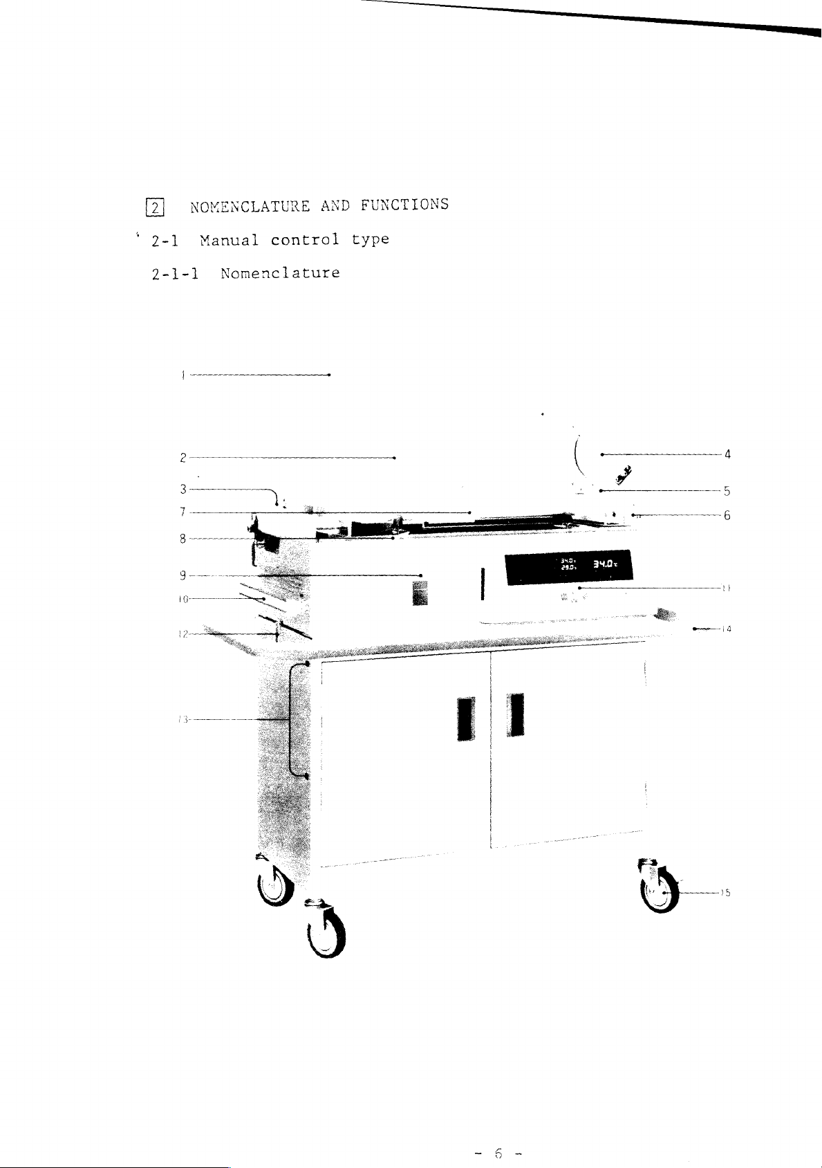
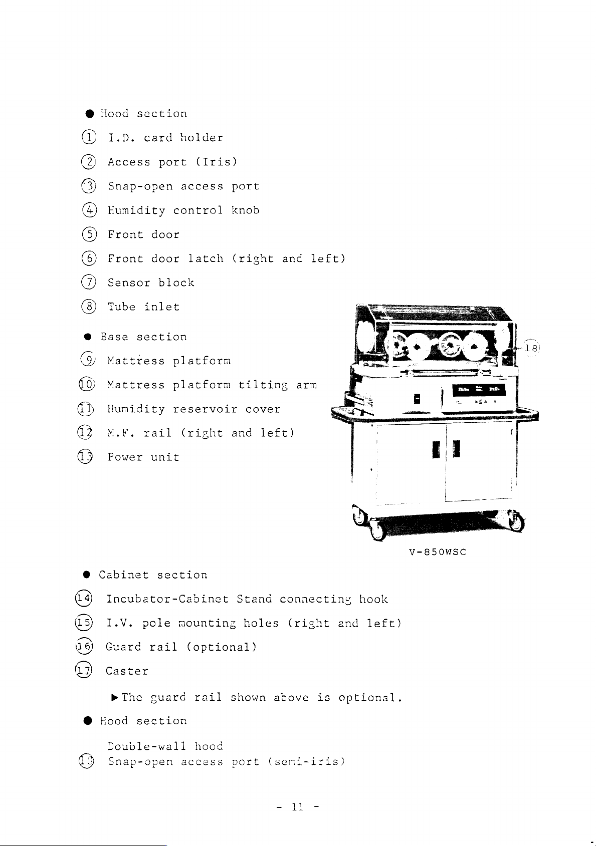
NOMENCLATURE
AND
FUNCTIONS
"
2-1.
2-1-1
Manual
Nomenclature
control
type
ο...
Page 10
@
(1)
Hood
I.D.
section
card
holder
Access
Humidity
Snap-open
Sensor
Tube
GO
O
Base
Mattress
Mattress
Humidity
M.F.
Power
10000
O
Cabinet
port
block
inlet
section
rail
unit
section
(Iris)
control
auxiliary
platform
platform
reservoir
(right
knob
access
tilting
cover
and
port
arm
left)
Incubator-Cabinet
©
I.V.
Guard
© ©
Caster
©
2-1-2
The
minimizes
ture
internal
prescribed
Power
microprocessor
variation
pole
temperature
rail
the
level.
mounting
(optional)
unit
stress
by
Stand
holes
p
The
guard
in
the
on
the
preventing
around
connecting
(right
rail
Manual
infant
overshoot
the
and
shown
Control
from
infant
hook
left)
above
Type
environmental
and
within
ATOM
controlling
*1/4°C
is
optional.
Incubator
tempera-
the
of
the
Page 11
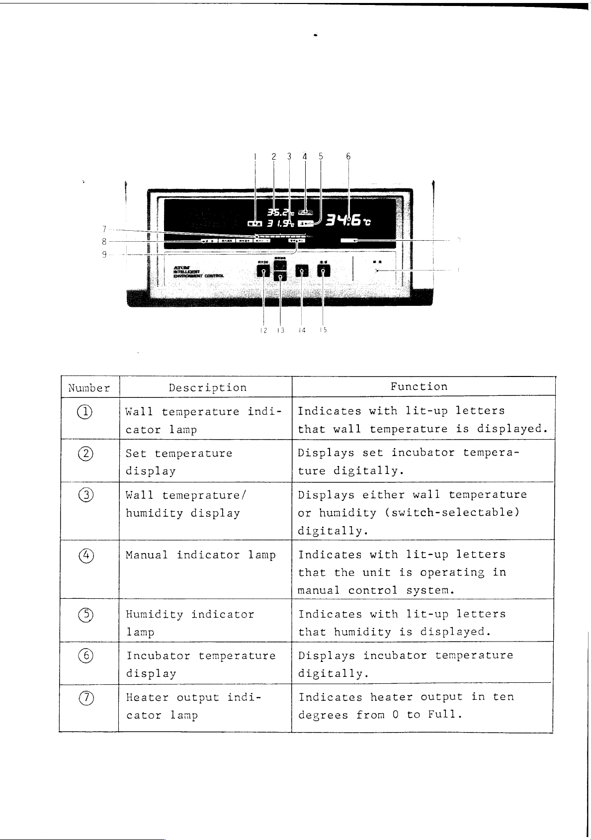
Number
©
(2)
Wall
cator
Set
display
Wall
humidity
Manual
Humidity
lamp
Incubator
temperature
temperature
temeprature/
Description
lamp
display
indicator
indicator
temperature
indi-
lamp
Indicates
that
Displays
ture
Displays
or
digitally.
Indicates
that
manual
Indicates
that
Displays
wall
digitally.
humidity
the
control
humidity
Function
with
temperature
set
either
with
unit
with
incubator
lit-up
incubator
wall
(switch-selectable)
lit-up
is
systen.
lit-up
is
temperature
operating
displayed.
temperature
letters
is
displayed.
tempera-
letters
letters
in
display
Heater
cator
output
lamp
indi-
digitally.
Indicates
degrees
heater
from
0
to
output
Full.
in
ten
Page 12
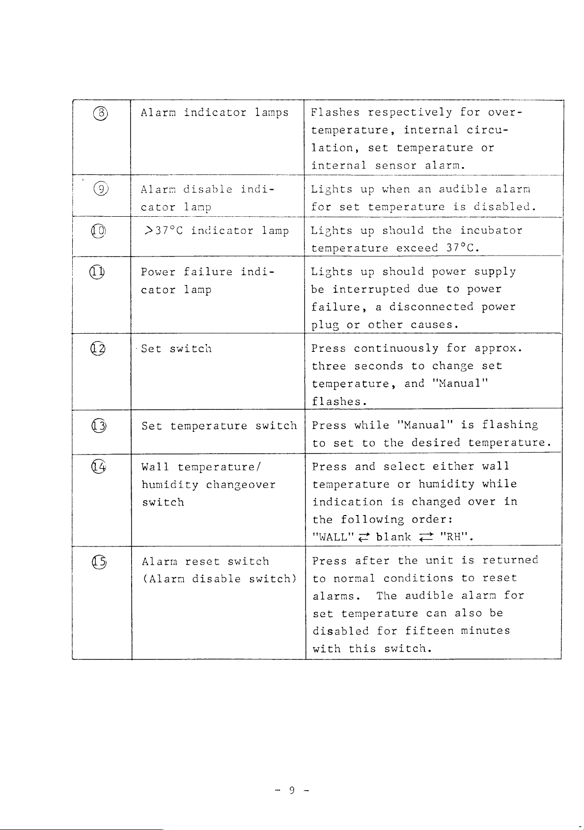
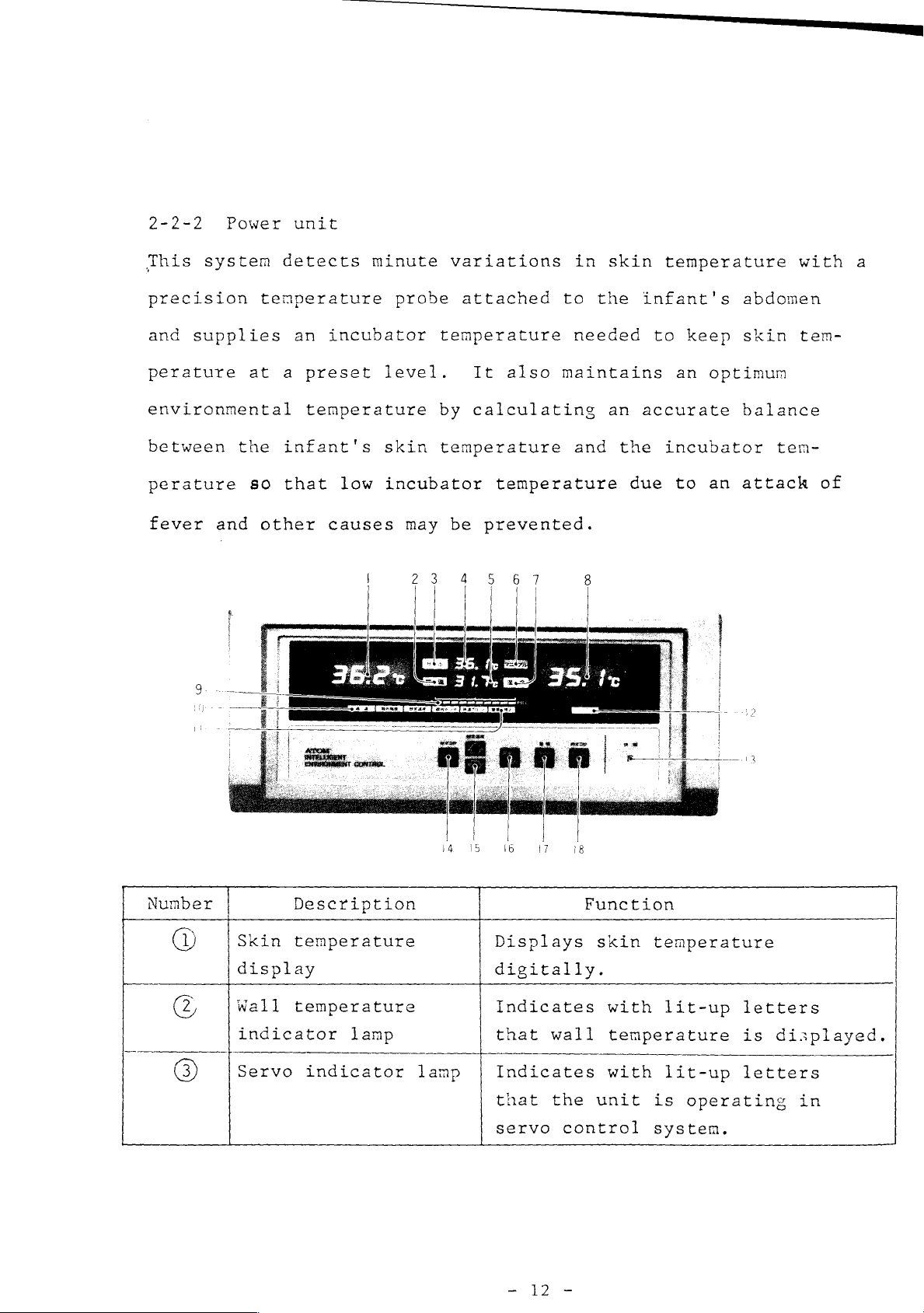
Alarm
indicator
lamps
Flashes
respectively
for
over-
temperature,
lation,
Alarm
cator
>37°C
Power
cator
-Set
disable
lamp
indicator
failure
lamp
switch
indi-
lamp
indi-
internal
Lights
for
Lights
temperature
Lights
be
interrupted
failure,
plug
Press
three
temperature,
flashes.
set
up
set
temperature
up
up
or
other
continuously
seconds
internal
temperature
sensor
when
should
should
a
an
exceed
due
disconnected
causes.
to
and
alarm.
audible
is
the
incubator
37°C.
power
to
for
change
"Manual"
circu-
or
alarm
disabled.
supply
power
power
approx.
set
Set
temperature
Wall
humidity
switch
Alarm
(Alarm
temperature/
reset
disable
switch
changeover
switch
switch)
Press
to
Press
temperature
indication
the
"WALL"
Press
to
alarms.
set
disabled
with
while
set
to
the
and
select either
following
2
blank
after
normal
temperature
this
conditions
The
for
"Manual"
desired
or
is
changed
order:
the
audible
fifteen
switch.
humidity
2
"RH".
unit
can
also
is
flashing
temperature.
wall
while
over
is
to
alarm
minutes
in
returned
reset
for
be
Page 13
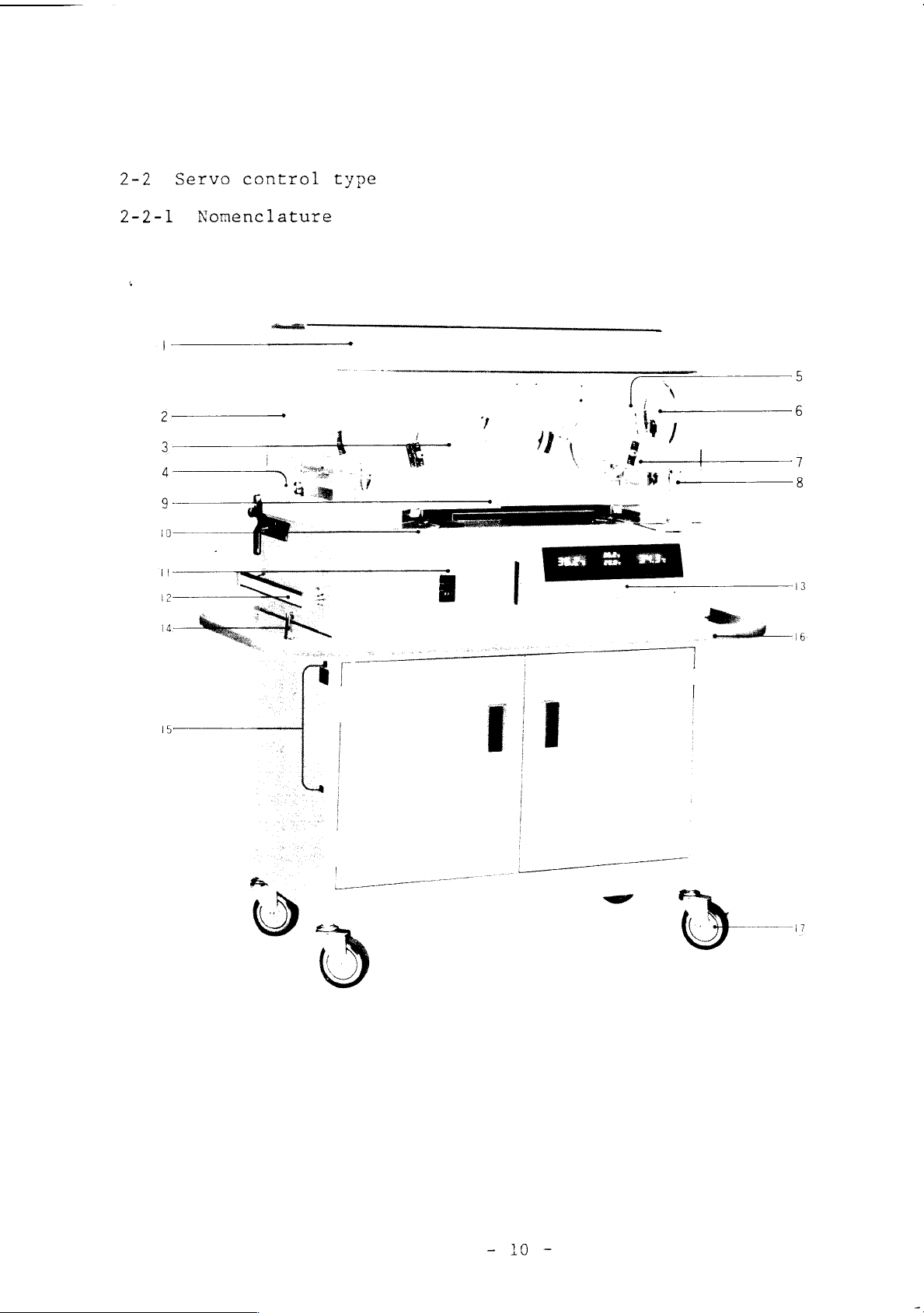
2-2
Servo
control
type
2-2-1
Nomenclature
Page 14
@
Hood
section
(1)
I.D.
Access
Snap-open
Humidity
Front
Front
Sensor
Tube
60000
O
Base
(9)
Mattress
(0)
Mattress
02
Humidity
02
M.F.
card
port
door
door
block
inlet
section
rail
holder
(Iris)
access
control
latch
platform
platform
reservoir
(right
port
knob
(right
tilting
cover
and
left)
and
arm
left)
43
Power
O
Cabinet section
Incubator-Cabinet
9
(6)
43
I.V.
Guard
Caster
©
Hood
Double-wall
dI
pole
»
The
section
Snap-open
unit
rail
guard
mounting
(optional)
rail
hood
access
Stand
holes
shown
port
connectiny
(right
above
(semi-iris)
and
is
optional.
V-850WSC
hook
left)
Page 15
2-2-2
This
precision
and
perature
environmental
between
perature
fever
Power
system
supplies
at a preset
the
so
and
unit
detects
temperature
an
incubator
temperature
infant's
that
other
low
causes
minute
probe
temperature
level.
by
skin
incubator
temperature
may
variations
attached
It
also
calculating
temperature
be
prevented.
in
skin
to
the
needed
maintains
an
and
the
due
temperature
infant's
to
keep skin
an
accurate
incubator
to
abdomen
optimum
balance
an
attack
with
tem-
tem-
a
of
Number
(1)
ο
(3)
Skin
display
Wall
indicator
Servo
Description
temperature
temperature
lamp
indicator
lamp
Displays
digitally.
Indicates
that
Indicates
that
servo
Function
wall
the
control
skin
unit
temperature
with
temperature
with
lit-up
lit-up
is
system.
letters
is
letters
operating
displayed.
in
|
Page 16
Set
temperature
Displays
digitally
either
set
display
Wall
©
humidity
Manual
(©)
Humidity
©
©)
lamp
Incubator
display
temperature/
display
indicator
indicator
temperature
lamp
skin
control
temperature
system.
is
Displays
ture
selectable)
Indicates
that
manual
Indicates
that
Displays
digitally.
temperature
selectable.
or
the
control
humidity
system
in
Either
either
humidity
digitally.
with
unit
with
incubator
in
or
set
manual
control
wall
(switch-
lit-up
is
operating
system.
lit-up
is
displayed.
servo
incubator
control
system
tempera-
letters
in
letters
temperature
9
©
©
©
©)
Heater
cator
Alarm
Alarm
cator
>
37°C
Power
cator
output
lamp
Indicator
disable
lamp
indicator
failure
lamp
indi-
lamps
indi-
lamp
indi-
Indicates
degrees
Flashes
temperature,
tion,
sensor
probe
Lights
for
set
Lights
temperature
Lights
be
interrupted
failure,
plug
or
heater
from
respectively
set
temperature,
or
skin
alarm.
up
when
temeprature
up
should
exceed
up
should
a
disconnected
other
output
0
to
Full.
internal
temperature
an
audible
the
power
due
causes.
37°C.
to
in
for
over-
circula-
internal
is
disabled.
incubator
supply
power
power
ten
alarm
Page 17
(3
Set
switch
Press
continuously
for
approx.
three
temperature,
(9
(9
(2
Set
temperature
Wall
hunidity
switch
Alarm
(Alarm
tenperature/
changeover
reset
disable
switch|
switch
switch)
tion"
Press
(Servo/Manual)
set
Press
temperature
indication
the
"Wall"?
Press
to
alarms.
set
abled
seconds
(Servo/Manual)
while
to
the
and
following
blank
after
normal
The
temperature
for
to
and
"mode
is
desired
select
or
humidity
is
changed
order:
22
the
unit
conditions
audible
can
fifteen
change
"mode
of
flashing
either
"RH"
minutes
of
flashes.
operation"
temperature.
over
is
to
alarm
also
set
opera-
to
wall
while
in
returned
reset
for
be
dis-
with
(8
2-3
The
to
provide
by
precise
supply.
Room
are
mixed.
Servo/Manual
over
Air
circulation
air
circulation
air
and
switch
an
optimum
temperature
oxygen
change-
system
system
atmospheric
control,
enter
this
Press
three
Servo
of
V-850
of
V-850
environment
humidification
the
unit
through
switch.
continuously
seconds
or
Manual.
incubator
ATOM
Incubator
the
to
for
and
filter
for
select
is
the
oxygen
approx.
either
designed
infant
and
then
Page 18
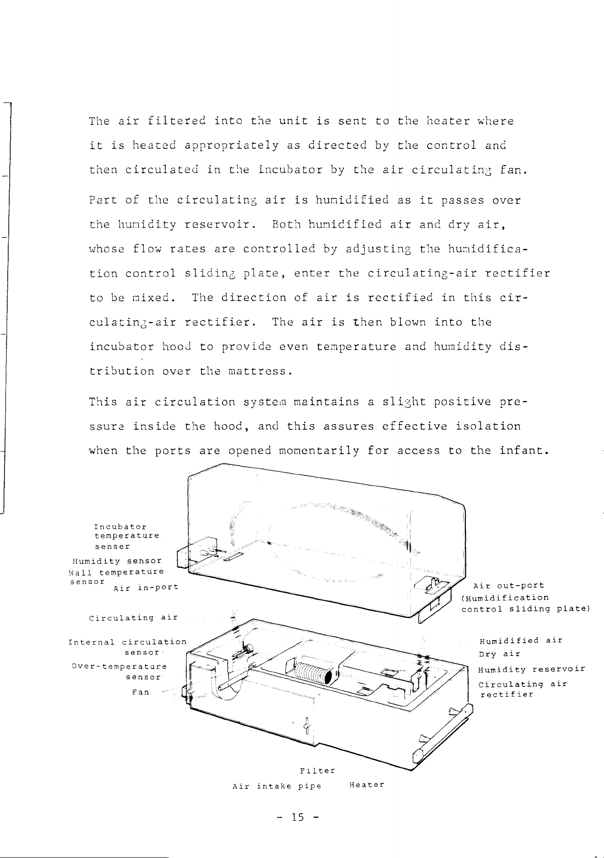
The
air
filtered
into
tne
unit
is
sent
to
the
heater
where
it is
then
Part
the
whose
tion
to
culating-air
incubator
tribution
This
ssure
heated
circulated
of
the
humidity
flow
control
be
mixed.
air
inside
appropriately
in
circulating
reservoir.
rates
sliding
The
rectifier.
hood
over
circulation
the
to
the
hood,
the
are
controlled
plate,
direction
provide
mattress.
system
as
incubator
air
is
Both
enter
of
The
air
even
maintains
and
this
directed
by
the
humidified
humidified
by
adjusting
the
air
is
is
then
temperature
assures
by
the
control
air
circulating
as
it
passes
air
and
dry
the
hunidifica-
circulating-air
rectified
blown
and
a
slizht
effective isolation
in
this
into
humidity
positive
and
fan.
over
air,
rectifier
cir-
the
dis-
pre-
4
when
Incubator
Humidity
Wall
sensor
Circulating
Internal
Over-temperature
temperature
senser
temperature
Air
circulation
the
sensor
in-port
sensor:
sensor
Fan
ports
air
一
are
opened
momentarily
for
access
to
the
infant.
Air
out-port
(Humidification
control sliding
Humidified
Dry
air
Humidity
Circulating
rectifier
plate)
air
reservoir
air
Air
intake
Filter
pipe
-
15
-
Heater
Page 19
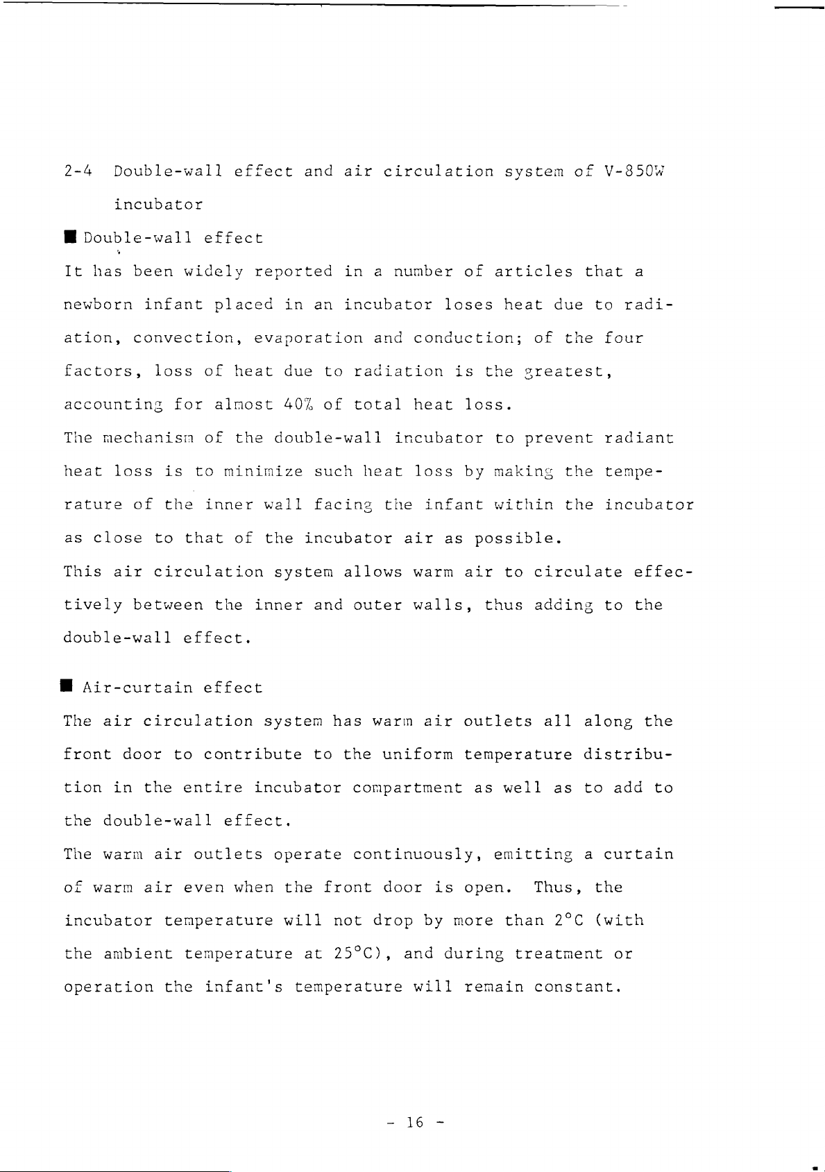
2-4
Double-wall
incubator
M
Double-wall
It
has
been
newborn
ation,
convection,
factors,
accounting
The
mechanism
heat
rature
as
This
loss
of
close
air
effect
widely
infant
loss
is
the
to
circulation
for
that
placed
of
almost
of
to
inner
effect
reported
evaporation
heat
the
double-wall
minimize
wall
of
the
system
and
in
an
due
to
40%
of
such
facing
incubator
air
circulation
in a number
incubator
and
conduction;
radiation
total
heat
incubator
heat
the
loss
infant
air
allows
warm
of
loses
is
loss.
by
as
possible.
air
system
articles
heat
the
greatest,
to
prevent
making
within
to
of
that
due
to
of
the
the
the
circulate
V-850W
a
radi-
four
radiant
tempe-
incubator
effec-
tively
double-wall
E
Air-curtain
The
air
front
tion
the
The
of
door
in
double-wall
warm
warm
incubator
the
ambient
operation
between
effect.
circulation
to
the
entire
air
outlets
air
even when
temperature
temperature
the
the
inner
effect
system
contribute
incubator
effect.
operate
infant's
and
has
to
the
the
front
will
at
not
25°C),
temperature
outer
warm
walls,
air
uniform
compartment
continuously,
door
drop
by
and
is
during
will
thus
outlets
temperature
as
well
emitting
open.
more
than
treatment
remain
adding
all
along
distribu-
as
to
a
Thus,
2°C
constant.
to
the
add
curtain
the
(with
or
the
to
Page 20
Humidity
Wall
sensor
Incubator
temperature
senser
temperature
Air
Circulating
sensor
in-port
air
Air
curtain
Air
(Humidification
control
out-port
sliding
plate)
Internal
Over-temperature
sensor
circulation
s
ensor
Fan-
İk
Lİ
グン
um
=
o
EE
1
7
“O
|
q
<.
Filter
Air
intake
pipe
Heater
Humidified
Dry
air
Humidity
Circulating
rectifier
air
reservoir
air
Page 21
3-1
(1)
(2)
3-2
INCUBATOR
Room
The
preferably
radiant
Avoid
a
heating
tions
Always
heat
Power
Use
a
INSTALLATION
temperature
room
source.
heat
placing
may
keep
outlet
power
in
apparatus
adversely
which
have
loss
the
the
and
outlet
and
influence
the
incubator
a
temperature
from
incubator
or
affect
incubator
grounding
near
the
near
at
the
of
outside
is
over
incubator.
in
direct
a
cold
the
incubator
least
incubator
to be
23°C
sunlight,
window
150cm
to
temperature
installed
to
minimize
as
such
temperature.
away
prevent
from
should
the
close
accidental
to
loca-
a
contact
for
each
This
connect
It
is
a
ground
If
no
tor
is
with
incubator.
unit
Rated
Frequency
Power
recommended
ground
is
the
voltage
consumption
terminal.
to
be
a
trailing
rated
unit
to
that
terminal
connected,
at
any
power
the
voltage
power
the
exists
ask
cord.
source
As
specified
As
specified
"MC"
"Oc"
power
in
hospital
specified
280VA
outlet
the
room
Use
a
separate
by
you.
of a different
utilized
where
service
the
personnel
outlet
Do
voltage.
include
incuba-
not
to
Page 22

provide
a
ground
connection.
If
the
available
ground
terminal
ground
Ground
is
located
cord,
an
peripneral
beyond
additional
electric
the
reach
length
of
instruments
of
the
wire
securely.
incubator's
can
be
added.
19
Page 23
OPERATING
4-1
The
perature
in a vacant
tnat
Incubator
doctor's
4-1-1
(1)
Operation
operator
the
Preparation
Attach
10-2
INSTRUCTIONS
of
should
test
unit
instructions.
and
state
operates
temperature
access
on
Ρ.65
manual
fully
operation
prior
port
)
to
properly.
should
covers
control
familiarize
procedures
placing
be
set
to
type
an
iris
himself
by
infant
in
accordance
access
with
operating
in
it,
ports
the
the
and
with
(See
ten-
incubator
ensure
the
(2)
4-1-2
(1)
Get
ready
control
HUMIDITY
Power
Make
are
sure
securely
for
sliding
CONTROL
source
that
humidity
plate
on
the
power
connected
control.
to
P.38
to
the
lowest
),
cord
and
appropriate
Set
the
the
humidification
level
sensor
connecting
(See
connector
ports
Page 24
on
the
side
panel
respectively.
Γι
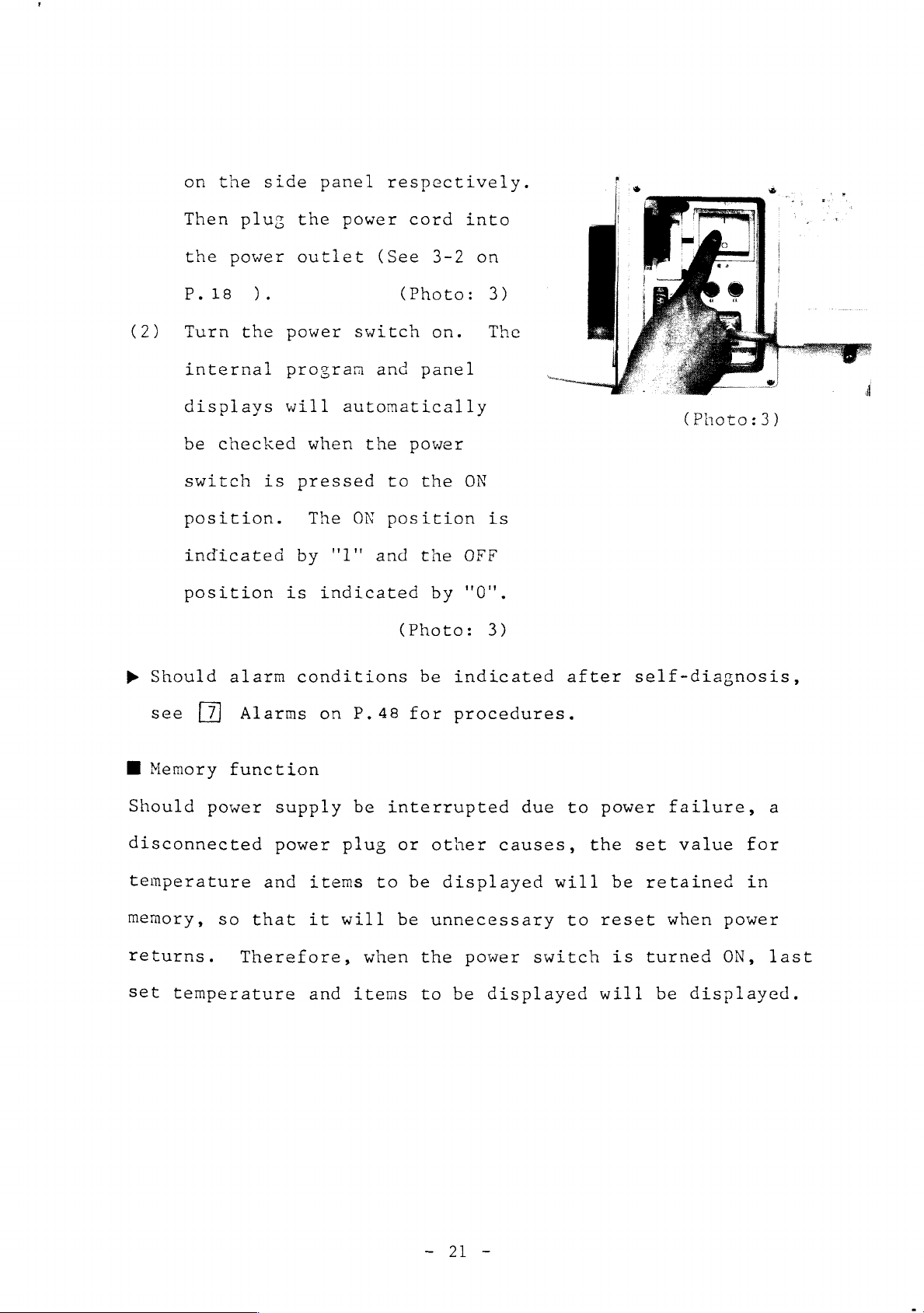
(2)
Then
the
P.18
Turn
plug
power
).
the
internal
displays
be
checked
switch
position.
indicated
position
the
outlet
power
program
will
is
pressed
by
is
power
(See
switch
and
automatically
when
The
the
ON
"l"
and
indicated
cord into
3-2
(Photo:
on.
panel
power
to
the
position
the
by
(Photo:
on
3)
The
(Photo:3)
ON
is
OFF
"0".
3)
>
Should
see
M
Memory
Should
power
disconnected
temperature
memory,
returns.
set
so
temperature
alarm
conditions
Alarms
function
supply
power
and
that
Therefore,
on
plug
items
it
will
and
P.48
be
interrupted
or
to be
be
when
items
be
indicated
for
procedures.
other
displayed
unnecessary
the
power
to
be
due
causes,
will
switch
displayed
after
to
power
the set
be
to
reset
will
self-diagnosis,
failure,
value
retained
when
is
turned
be
displayed.
for
in
power
ON,
a
last
Page 25
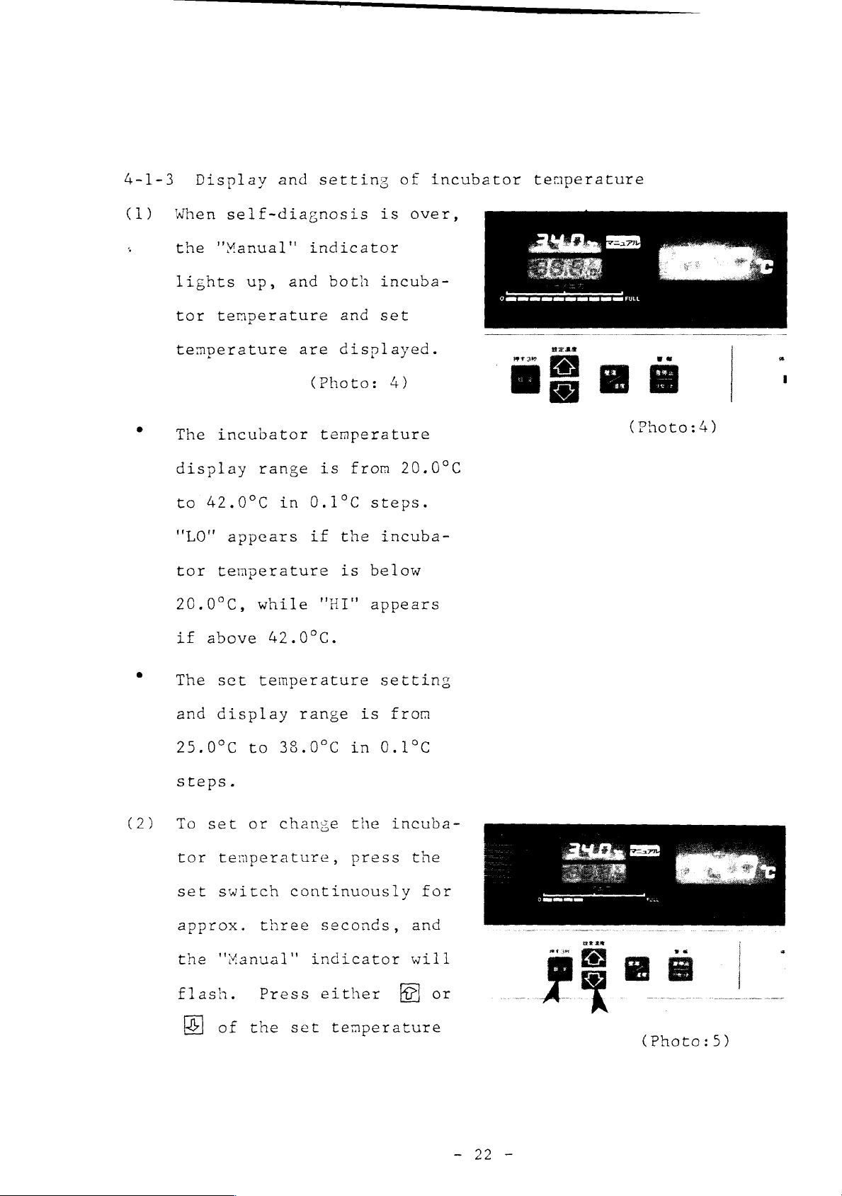
4-1-3
(1)
Display
When
the
lights
tor
self-diagnosis
"Manual"
up,
temperature
temperature
The
incubator
display
to
42.0°C
"LO"
tor
appears
temperature
and
and
range
in
setting
indicator
both
and
are
displayed.
(Photo:
temperature
is
from
0.1°C
if
the
is
of
is
over,
incuba-
set
4)
20.0°C
steps.
incuba-
below
incubator
rr
temperature
rre
р
TAP
ad
uae
Photo:4)
(2)
20.0°C,
if
above
The
set
and
display
25.0°C
steps.
To
set
tor
temperature,
set
switch
approx.
the
"Manual"
flash.
while
"HI"
42.0°C.
temperature
range
to
38.0°C
or
change
continuously
three
Press
seconds,
indicator
either
appears
setting
is
in
0.1°C
the
press
from
incuba-
the
for
and
will
or
of
the
set
temperature
(Photo:5)
22
Page 26

to
the
desired
level.
(3)
The
set
temperature
changed
while
indicator
Setting
"Manual"
flashing
Wait
till
is
about
the
indicator
and
incubator
stabilizes.
stabilization
on
the
ambient
the
is
flashing.
complete
lights
50
to
(Time
varies
(Photo:
can
5)
be
"Manual"
when
stops
up.
60
minutes
temperature
needed
depending
temperature.)
the
for
When
stabilizes
temperature
output
between
bator
state,
Ш
Heater
The
heater
supplied
temperature.
desired
temperature,
the
indicator
is
output
output
as
required
incubator
around
and
0
and
now
As
the
temperature
the
the
heater
reads
1/2,
in
the
the
(Photo:
indication
indicator
to
maintain
incubator
the
set
steadily
incu-
steady
indicates
heat
6)
the
temperature
supply
ean
ον
ære
M
E
the
amount
incubator
rises
decreases
a
(Photo:6)
of
at
the
toward
and
the
πα
heat
desired
the
reading
Page 27

on
the
indicator
lowers
gradually
from
FULL,
and
when
the
desired
reading
O
and
1/2.
Thus
temperature
heater output
4-1-4
Should
exceed
cator
audible
The
unit
will
incubator
can
incubator
remains
control.
">
37°C"
the
incubator
37°C,
light
alarm
be
set
temperature
within
indication
indication
the
''>
up
sound.
temperature
up
to
the
balanced
temperature
37°C"
and
indi-
an
of
38°C.
is
helps
the
reached,
heat
to
supply
know
the
varying
heater
range
output
between
incubator
Therefore,
temeprature
temeprature
of
37-38ºC,
cator
alarm
incubator
a
4-1-5
Audible
internal
high
will
sound,
level.
Alarms
should
exceed
set
the " >37°C"
light
indicating
temperature
and
and
visible
circulation,
the
37°C
within
up
and
alarm
alarms
incubator
with
the
indi-
an
that
is
set
(Photo:
disable
set
temperature,
the
range
audible
the
to
7)
are
provided
for
over-temeprature,
internal
(Photo:7)
sensor
and
Page 28

power
failure.
The
audible
alarm
disabled
‘when
(alarm
the
pressed.
See
>
procedures
alarm
4-1-6
Press
humidity
for
set
for
alarm
disable
Alarms
[7]
is
Wall
the
wall
changeover
temeprature
fifteen
reset
switch)
(Photo:
on
to
follow
indicated.
minutes
switch
P.
is
48
if
is
8)
for
any
temeprature/humidity
temeprature/
switch
to
indication
(Photo:
8)
select
indication
tne
"Wall"
The
range
in
a
following
41
€
wall
is
0.1°C
display
in
1%
steps.
4-1-7
(1)
Placing
Raise
desired
is
changed
order:
bland
temperature
from
20.0°C
steps,
range
is
the
display
RE.
while
from
infant
lower
while
over
display
to
42.0°C
the
humidity
20%
to
(Photo:9
in
incubator
hood
front
in
99%
)
with
(ST
both
hood)
hands
and
(Photo:9
open
the
)
Page 29

‘position,
(2)
hood
backward
the
of
head
legs
The
to
closing
To
it
till
infant
the
to
to
hood
prevent
close
firmly
it
is
into
mattress
the
the
lock
accidentally.
the
and
on
left
right.
the
with
the
then
the
is
hood
hood,
the
tilted
locked
place
center
with
and
the
the
(Photo:10)
provided
fron
hold
left
^
+
«a
EN
\
a
名
Mit, $ SÅ
Va
W
(Photo:
on
A
ος
10)
(3)
hand,
on
hood
right
lock,
both
Open
very
To
access
clockwise
respectively.
pull
the
right
toward
hand
and
hands.
and
carefully.
open
or
port,
the
lock
side
you
with
to
release
close
close
gently
the
close
turn
or
counterclockwise
lever
of
the
the
the
with
(Photo:11)
hood
an
iris
its
knob
>
(Photo:11)
Page 30

(4)
The
auxiliary
port
at
the
right
side
is
provided
for
removing
of
on
4-2
The
perature
incubator
and
The
the
The
with
Operation
operator
ensure
incubator
doctor's
skin
the
soiled
the
elbow
P.29)
should
test
temperature
skin
and
in a vacant
that
temperature
instructions.
temeprature
against
of
servo
operation
the
material.
control
fully
state
unit
operates
referred
It
the
door
type
familiarize
procedures
prior
should
probe
be
to
in
attached
to
properly.
snaps
latch.
himself
by
placing
set
this
open
(See
operating
in
accordance
Manual
to
the
with
with
an
a
touch
4-2-2
the
the
infant
is
detected
infant's
(2)
tem-
in
with
it,
abdomen.
4-2-1
(1)
(2)
Preparation
Check
Should
Servo/Manual
three
Follow
manual
ture.
to
the
seconds
the
control
see
that
"Servo"
changeover
and
procedures
the
change
type"
"Manual"
indicator
switch
over
described
to
stabilize
indicator
be
illuminated,
continuously
to
"Manual".
in
4-1
the
is
illuminated.
press
for
"Operation
incubator
the
approx.
of
tempera-
Page 31

4-2-2
Placing
hood)
infant
in
incubator
(1.C.
hood,
double-wall
(1)
Open
door
and
place
the
incubator.
V-S50W
is
provided
outlets
door.
operate
a
curtain
Thus,
rature
than
the
I.C.
gently
the
double-wall
all
The
continuously,
of
the
incubator
will
2°C
(with
hood
toward
infant
with
along
warm
warm
not
front
you
(Photo:
incubator
warm
the
air
air.
drop
the
ambient
in
12)
air
front
outlets
emitting
tempe-
by
more
(Photo:12)
temperature
Place
center
with
and
Close
after
and
+
Ww
Do
designed
the
the
then
not
the
infant
of
the
head
legs
the
hood
placing
latch.
forget
as
at
25°C).
mattress
to
to
front
the
to
to
resist
on
the
the
infant,
latch
the
left
right.
door
the
accidental
front
door,
force
though
applied
it
by
is
the
so
Page 32

infant
>
Note:
in
Do
the
not
incubator.
open
the
hood
when
placing
the
infant
(2)
inside
A
gentle
on
snap-onen
through
When
push
completely.
V-850W
risis
prevent
as
the
port
closing
the
double-wall
access
it
touch
latch
access
spring
port
the
warm
will
by
action.
(Photo:
the
to
ports
greatly
the
opens
port
port,
close
incubator
inside
air
in
elbow
the
13)
the
affect
the
incubator
temperature.
ge
to
is
the
snap-open
incubator
provided
access
from
with
being
—
(Photo:13)
semi-
port
»
»
4-2-3
(1)
dissipated
NOTE
NOTE
or
Insert
probe
patient
connecting
1:
2:
access
Attachment
servo
the
plug
when
Check
Never
ports
control
skin
firmly
temperature
jack
the
again
leave
open
of
skin
unit
temeprature
on
access
that
the
for
temperature
into
probe
the
the
sensor
ports
the
port
incubator
the
infant's
are
is
with
probe
open.
completely
the
safety.
and
operation
front
closed.
door
of
|
(Photo:14)
Page 33

box
the
on
hood
the
and
right
lock.
side
of
The
(2)
temperature
the
probe
the
skin
display.
The
skin
range
42.0°C
appears
ture
"HI"
Attach
is
in
is
appears
the
detected
is
indicated
temperature
temperature
from
30.0°C
0.1°C
if
the
below
30.0°C,
if
skin
by
(Photo:
display
to
steps.
skin
tempera-
while
above
(Photo:
temperature
42.0°C.
on
14)
"LO"
15)
(Photo:15)
(Photo:
16)
probe
the
umbilicus
process
with
tape.
intended
alcohol
remove
soil
probe.
element
a
before
to
the
infant
and
along
non-irritative
Clean
probe
or
smegma
Place
at
the
the
site
lukewarm
embryonum
attaching
the
the
tip
between
ensiform
ventrimeson
adhensive
skin
with
water
heat
of
at
and
the
sensing
the
the
to
probe
Metal)
/
o
Va
УР
S
Page 34

onto
the
intended
skin
site,
ensuring
maintains
the
skin.
cord
with
appropriate
the
probe.
NOTE
the
1:
metal
maintains
with
NOTE
the
the
2:
doctor's
that
the
close
Secure
a
tape
distance
Make
skin.
Be
disk
an
sure
certain
airtight
instructions
metal
contact
the
at
(Photo:16)
heat
to
disk
with
probe
an
from
that
sensor
seal
follow
(3)
regarding
site
with
abdomen.
Check
in
the
by
display
after
the
stable.
attaching
infant's
the
intended
attaching
infant
the
skin
four
to
skin
the
probe
lying
on
temperature
five
the
minutes
probe
temperature
skin
its
that
is
—
emi
Page 35

(4) A Press
the
servo/nanual
changeover
ously
for
seconds
servo
control.
indicator
set
temperature
changed
feriperalture
O
temperature.
To
temperature,
<
set
switch
switch
approx.
to
chanse
lights
fron
or
the
to
change
press
tie
continuously
continu-
three
over
The
"Servo"
up
and
is
also
incubator
Sein
Ελ...
{Pootor
the
skin
the
for
to
the
Vs
14)
set
(Photo:17)
approx.
"Servo"
flash.
B
of
switch
dicator
set
the
the
desired
(Photo:18)
The
set
changed
indicator
Setting
three
indicator
Press
the
set
while
is
skin
temperature
while
is
the
flashing
temperature
level.
is
flashing.
complete
seconds,
will
either
temperature
"Servo"
to
(Photo:19)
can
the
"Servo"
when
©
and
or
be
in-
to
LIGE
ONMENT
NT
CONTROL
æn
ee
m
38.5
be
ehh
(Photo:18)
+
TEE
the
"Servo"
flashing
indicator
anc
lights
up.
stops
(Photo:19)
Page 36

The
set
temperature
settins
and
display
range
is
from
(6)
34.0°C
>
Be
the
As
toward
fue
vá
supply
the
ture
level.
sure
skin
the
heater
oc
re
infant's
to
to
temperature.
skin
tne
Cl
는 ー i L A
reguiredl
at
the
38.0°C
follow
temperature
set
teseratur
output
skin
preroribod
(Photo:
in
tne
+
I
to
mainte
tempera
0.1°C
doctor's
in
è
20)
steps.
r
instructions
M
LIGENT
IONMENT
CONTROL
when
setting
вазы
NEBR
The
may
should
temperature
function
temeprature
actuate.
B
heater
when
the
output
required
prescribed
heater
increase
the
output
unit
indicator
to
maintain
level.
output
temporarily
low
preventive
or
the
control
(See
indication
is
Operating
indicates
reading
incubator
oeratins
function
4-2-7
the
on
infant's
P
in
the
«3
5)
the
amount
servo
skin
mode,
of
heat
temperature
tne
heater
supplied
at
as
the
33
Page 37

The
the
heater
infant's
output
skin
reading
temperature
shows
not
control
only
but
the
functioning
also
that
of
of
low
incubator
control
temperature
M
NOTE:
the
following
*
If
the
the
infant's
accurately.
incubator
infant's
If
the
or
the
temperature
features
or
During
skin
temperature
skin
skin
infant's
prevention
which
the
the
points:
temperature
abdomen,
f
temeprature.
temperature
actuate
ambient
servo
the
probe
arm
and
in
temperature.
mode
it
will
operation,
probe
will
is
have
is
covered
warmed,
and
operating
response
is
not
not
detect
dislodged
nothing
with
or
if
temperature
to
the
(See
properly
it
4-2-7
pay
attention
the
accidentally,
to
do
a
blanket,
gets
incubator
on
P.35)
attached
temperature
with
wet
the
diapers
with
to
to
the
urine
ture
The
develop
To
change
servo-manual
seconds
The
skin
attached
accurately.
set
and
infant's
temperature
or
fluid
temperature
a
fever.
from
changeover
turn
skin
to
the
and
the
servo
the
temperature
display
infant's
cooled,
may
mode
switch
"Manual"
while
abdomen.
it
not
be
to
continuously
indicator
can
the
will
the
not
maintained
manual
always
skin
detect
should
mode,
for
approx.
lamp
temperature
be
monitored
on.
the
the
press
probe
tempera-
infant
the
three
on
the
is
Page 38

4-2-4
">37°C"
indication
Should
exceed
cator
audible
4-2-5
See
4-1-5
The
servo
skin
the
incubator
37°C,
will
temperature
light
alarm
Alarms
on
control
the
sound.
and
P.24.
temperature
''>
37°C"
up
and
alarm
type
alarm.
indi-
an
(Photo:21)
disable
is
provided
with
an
alarm
(Photo:
for
21)
the
4-2-6
See
4-2-7
The
automatically
temperature
the
is
incubator
Wall
4-1-6
Characteristics
temperature
servo
incubator
lower
than
temeprature/humidity
on
P.25
control
constant
temeprature
and
preventive
system
in
inverse
(at
temperature
the
set
when
select
of
skin
a
desired
servo
controls
proportion
the
when
temperature
the
control
function
set
the
infant's
indication
display.
and
the
incubator
to
the
skin
temperature)
infant's
or
skin
low
infant's
skin
by
lowering
temperature
incubator
temperature
skin
by
raising
temperature
the
is
Page 39

higher
The
unit
ventive
from
and
when
perature
dropping
the
the
Should
temperature
perature
temperature.
than
the
is
provided
function,
operating
ambient
is
maintained
the
will
set
which
due
to
temperature
temperature
infant's
by
less
be
On
skin
with
temeprature.
prevents
the
infant's
in
skin
than
limited
the
other
the
low
control
has
the
following
temperature
0.5°C,
to
be
hand,
incubator
the
incubator
fever
function,
dropped.
the
within
should
and
The
manner.
exceed
lowest
5°c
it
temperature
temperature
other
of
causes,
which
infant's
the
preselected
incubator
the
skin
exceed
pre-
actuates
ten-
ten-
the
pre-
selected
temeprature
Therefore,
is
controlled
(Example)
temeprature
will
the
Should
the
incubator
5°C
incubator
be
incubator
within
pre-selected
of
31.8°C
pre-selected
reach
by
limited
the
the
skin
temperature
the
temeprature,
temperature
Should
37.2°C,
more than
to
be
temperature
range
of
temperature
temperature
the
skin
temperature
the
lowest
0.5°C,
no
lower
during
25-38°C.
rise
is
limited
that
in
this
temperature
by
more
incubator
the
lowest
than
servo
to
36.5°C,
to
is,
the
example
than
incubator
25°C.
control
36.8°C
the
be
lowest
will
with
lowest
within
be
exceed
0.5°C
temeprature
the
and
will
be
25°C.
Page 40

Should
the
ambient
temeprature
drop
exceedingly
for
some
cause
lation
and
between
temperature
perature"
The
"operating
total
vection
the
effect
on
air
temperature
calculation.
operating
ment
for
the
wall
the
will
and
the
temperature“
of
the
incubator
Hey*
temperature
an
infant
To
=
temeprature
wall
be
calculated
incubator
the
air
but
and
in
0.6Tw
temeprature
temeprature
represents
temperature,
temperature
also
others
to
represent
the
incubator.
+
04TA
drop
by
using
the
wall
recommend
accordingly,
and
the
"operating
will
quantitatively
radiation
by
using
temeprature
the
the
thermal
the
incubator
be
raised.
and
not
only
in
use
of
environ-
re-
tem-
con-
this
The
operating
and
the
Operating
(Example)
temperature
incubator
temperature
If
the
the
=
То
Heat
incubator
erating
above
(To:
incubator
operating
perature,
temeprature
wall
Ta:
for
may
not
temperature
temeprature
temperature,
incubator
this
is
controlled
drop
(0.6X26)+(0.4X32)=28.4°C
will
be
temperature
temperature
the
pre-set
supplied
level
by
may
currently
unit
below
drops
32.0°C,
the
rise
of
29°C.
Tw:
air
temeprature)
is
set
so
29°C.
to
26.0°C
heater
and
28,49C
wall
to
that
so
thus
may
tem-
29°C,
the
with
that
the
rise
the
op-
*
Reference:
Hey,
Recent.
E.N.,:
Adv.
The
in
Care
Ped.,
of
4:171,
Babies
in
1971.
Incubator.
Page 41

HUMIDITY
Humidity
perature
instructions.
(1)
Open
cover
dity
see
fin
the
sterile
the
The
CONTROL
control
has
stabilized,
the
humidity
and
take
reservoir.
that
is
humidity
tne
properly
distilled
prescribed
reservoir
must
be
effected,
in
reservoir
out
the
Check
humidification
set.
reservoir
water
level
capacity
"—".
accordance
huni-
to
Fill
with
to
is
after
Correct
reservoir
the
with
incubator
the
doctor's
fitting
seal
ten-
i.
(Photo:22)
of
humidity
about
NOTE
reservoir
attach
humidity
should
NOTE
fication
humidity
fitted
wihtout
1:
2:
1.62.
(Photo:22)
Hold
with
or
detach
reservoir
be
kept
Even
is
reservoir
to
the
any
the
both
closed.
when
needed,
incubator
water
(Photo:23)
humidity
hands
it.
cover
no
the
should
in
it.
The
humidi-
to
be
module
O
Proper
x
Improper
Improper
Black
二
8
roundí0)
~
一
Exp
(PHoto:23)
Page 42

>
NOTE
not
3:
fitted
If
the
at
humidity
all
or
is
reservoir
fitted
only
top
cover
improperly,
or
seal
it
is
will
(2)
(3)
lead
(See
The
to
the
water
below
Supply
be
checked
Change
Fill
at
the
tne
humidity
sterile
air
figures.)
level
the
prescribed
distilled
from
the
reservoir
water
lower
sensor
distilled
or
part
oxygen
in
the
water
outside
reservoir
of
with
water.
leakage.
humidity
level
as
the
water
the
indicated
needed.
humidity
every
Avoid
reservoir
by
The
reservoir
24
hours.
such
the
water
(Photo:
mistakes.
should
broken
level
cover.
23)
ranaaity
not
tty
be
line.
can
sdneor
i
The
accompanying
or a syringe
conveniently
filling.
Next,
humidity
humidity
down
Change
the
hunidity
24
in
water
hours.
fit
sensor
sensor
the
the
sensor
will
used
the
accompanying
wetty
and
water
(Photo:
distilled
reservoir
wetty
filler
be
for
to
hang
reservoir.
24)
water
and
every
the
it
the
in
(Photo:
24)
Page 43

M
Prevention
the
humidity
of
multiplication
reservoir
and the
of
micro-organisms
water
reservoir
in
Addition
1:10,000
to
the
hunidity
the
multiplication
organisms.
with
available
voir/water
inhibit
micro-organisms
the
numidity
water
of
silver
distilled
reservoir
silver
for
reservoir)
the
reservoir.
1.5
to
2.5m%
nitrate
water
will
of
micro-
Silvita
steam
humidity
multiplication
if
reservoir
(optional,
attached,
will also
placed
Clean
of
solution
in
the
inhibit
reser-
of
in
and
the
Silvita
Silvia
for
humidity
reservoir
-
(Photo:25)
Water
"“Silvita
reservoir
for
gently
with
solution,
soils
(4)
a
The
sliding
the
position
temperature
Push
with
disinfectant
found
a
once
on
humidification
plate
minimum
the
soft
until
humidity
cloth
detergent
a
week,
the
surface.
must
humidification
the
has
stabilized.
soaked
and
remove
control
be
in
incubator
control
(Photo:
25)
Page 44

knob
provided
on
the
left
(5)
side
the
projection
cation
Nhen
rature
the
sliding
desired
If
hood
of
inside
the
humidification
the
is
the
hood
arm
on
the
control
(Photo:
incubator
has
stabilized,
plate
humidity
temeprature
much
to
higher
and
to
catch
humidifi-
slicing
26)
tempe-
control
the
level.
in
than
cause
the
plate.
set
the
(Photo:
26)
(6)
that
incubator
inner
in
with
natural
not
of
the
If a higher
than
of
the
wall
some
humidity
cases
moisture.
phenomenon
mean
incubator.
is
achieved
room
is
of
any
generated
humidity
where
installed,
the
hood
be
clouded
This
and
excessive
with
the
the
may
is
a
does
level
within
is
needed
the
up
Page 45

humidification
control
Seal
cu,
Humidification
sliding
maximum
the
humidification
in
the
with
hish
Press
:
aunioity
to
The
lamp
hunidity
witain
S9
the
humidification
sis
+
La
have
1
humidity
will
ноя
in
plate
position,
humidity
acconpanying
the
wall
Le
chan
和
hunidity
light
will
lye
the
ranre
1%
steps.
set
to
cover
fin
reservoir
(Photo:
temeprati
.
.
cover
o
E
Cisplayed.
indicator
up
and
be
displayed
re
Е
$
of
>
Paoto:22)
the
pad.
27)
Lire:
switcn
the
A
20
-
(Photo:
HM
c
ω
—
27)
(Photo:
28)
Pres
Press
display
over
for
selection:
"wall"
tne
in
ne
will
tne
272
sltch
switch,
be
following
blank
1
and
changed
ivi"
ine
tne
order
Page 46

[6]
The
OXYGEN
oxygen
SUPPLY
concentration
must
be
determined
in
accordance
with
Close
incubator
(1)
the
attention
Always
flowmeter
administer
desired
the
the
in
and
doctor's
during
use
oxygen
oxygen
the
oxygen
adjust
“instructions.
snould
oxygen
the
(optional)
oxygen
flow
rate.
supply
inlet
the
(Photo:
be
administration.
oxygen
at
Connect
hose
located
supply
flowmeter.
29)
paid
to
a
to
valve,
to
the
humidity
level
in
the
AE
(Photo:29)
(2)
>
NOTE:
supply
humidified
the
humidified
the
result
oxygen
When
below
Do
not
valve
oxygen.
oxygen
humidifier
an
40%
supply
oxygen
in
malfunction
supply
oxygen
is
use
the
oxygen
when
desired
supplying
Use
valve
supply
bottle
valve.
concentration
in
of
during
may
of
the
from
the
Page 47

incubator,
oxygen
indicating
on
In
of
the
automatically,
excess
charged
ne
administration
the
oxygen
this
oxygen
case,
incubator
oxysen
from
table
supplied
below
fit
plate
supply
(Photo:
the
is
gas
the
the
nigh
(red)
amount
into
adjusted
and
any
is
incubator.
shows
port.
30)
dis-
the
oxygen
concentration
(Photo:
level
30)
in
(3)
the
incubator
up
of
These
without
figures
Oxygen
Oxygen
When
over
the
high
tion
from
the
oxygen
values
an
infant
should
flow
concentration
an
incubator
40%
is
desired,
oxygen
indicating
the
oxygen
after
supply
were
be
rate
administra-
plate
supply
20 - 30
at
obtained,
in
the
incubator.
considered
(Ÿ/min)
(4%)
oxygen
level
remove
(red)
port
minutes
the
oxygen
and
only
2
28-31
are
as
following
flow
therefore
So
oxygen
estimated
3
32-36
the
rates
appropriate,
4
37-40
start-
listed.
flow
values.
and
adjust
the
oxygen
flowmeter
Page 48

to
supply
oxygen
at
a
desired
removed
nistration
plate
the
warn
that
oxyzen
he
about
(Increase
concentration
rate.
high
(rec)
rear
all
high
is
oxygen
40
of
tne
minutes
Hans
oxygen
indicating
on
the
the
nursing
concentration
now
being
concentration
the
oxygen
is
the
o
admi-
hook
hood
supplied.
(Photo:
after
lower
on
to
staff
31)
the
flow
than
in
oxygen
rate
f
:
the
incubator
when
desired,
supply
the
and
on
(Photo:
stabilizes
is
started.
incubator
conversely,
31)
oxygen
decrease
Strict
concentration,
level
minute
incubator
NOTE:
must
when
Je
x
If
oxygen
room
the
attention
in
the
intervals)
stabilizes.
The
not
be
high
air
oxygen
supply
is
flow
by
incubator
high
removed
admitted
rate
must
monitoring
till
oxygen
from
(over
fails
automatically
when
be
with
the
administration
40%)
during
paid
oxygen
the
the
to
the
an
oxygen
oxygen
is
being
high
concentration
variations
oxygen
concentration
oxygen
tirouzh
concentration
monitor
indicating
supply
administered.
is
higher.)
in
oxygen
(at
10-
in
tne
plate
port
administration,
the
except
emergency
Page 49

ventilation
ports
provided
around
the
oxygen
supply
port
a
close
oxygen
M
General
The
oxygen
vary
racy
the
with
proper
depending
of
the
oxyzen
an
accurate
oxygen
concentration
for
accuracy
for
additional
watch
administration.
Precautions
concentration
on
the
oxygen
concentration
oxygen
concentration
meter
with
atmospheric
patient
on
the
oxygen
for
Oxygen
level
operating
flowmeter,
level
concentration
to
be
used
within
and
in
level
should
oxygen
safety.
supply
status
Administration
the
condition
other
the
factors.
incubator
meter
in
the
be
periodically
(20.9%)
However,
during
incubator
of
the
repeatedly
to
maintain
incubator.
and
maintain
will
unit,
Measure
pure
high
accu-
the
The
checked
oxygen.
Be
sure
optimum
basis
sured).
>
NOTE:
an
infant
of
the
of
retinopathy).
formerly
prove
the
incubator
to
follow
oxygen
PO?
concentration
(value
Administration
with
infant
cardiopulmonary
developing
Oxygen
considered
dangerous.
is
the
of
However,
not
doctor's
level
arterial
of
oxygen
retrolental
concentrations
safe
for
when
sufficient
instructions
in
the
incubator
oxygen partial
concentrations
diseases
increases
fibroplasia
under
infants,
the
to
may
oxygen
maintain
to
determine
on
pressure
over
the
(infant
40%,
also
which
possibly
concentration
the
arterial
the
40%
the
mea-
to
risk
were
in
Page 50

oxygen
partial
pressure
within
the
normal
ranze,
a
concent-
*
ration
Therefore,
needed,
ssary
incubator
to
of
to
determine
60%,
in
it
is
measure
repeatedly
the
80%
or
cases
reported
the
oxygen
more
where
to
oxygen
and
analyze
concentration
is
said
a
high
be
concentration
oxysen
extremely
the
to
be
arterial
level.
necessary.
environment
important
level
blood
and
in
is
the
~
©
nece-
gases
Page 51

Action:
Alarm
Alarm
Is
port,
sensor
bator
sensor
the
being
disable:
reset:
the
main
the
air
covered
temperature
wetty?
malfunction,
out
of
Press
able
be
disabled
switch).
illuminated
Should
alarm
deck
in-port
with
If
order.
the
for
another
disable,
placed
diapers,
sensor
the
the
unit
alarm
The
and
fifteen
alarm
the
properly?
or
the
covered
above
should
reset
alarm
the
minutes.
conditions
alarm
incubator
etc.?
with
checks
be
switch
disable
audible
will
Isn't
temperature
Isn't
the
fail
to
considered
(the
indicator
alara
occur
be
reset
the air
the
incu-
hunidity
identify
as
alarn
will
dis-
be
during
automa-
out-
will
In
(2)
selected
temperature
Figure
case
ture
and
drops
an
the
servo
hould
the
will
the
by
power
below
intermittent
tically.
when
mode
infant's
temperature
indicator
flash,
skin
more
temperature
than
supply
the
It
will
the
unit
of
operation
skin
by
more
lamp
and
an
1°C,
to
the
a
heater
pre-selected
audible
alarm
also
is
returned
temeprature
than
and
the
audible
exceeds
continuous
will shut
temperature
will
be
reset
to
deviate
11°C,
skin
alarm
the
pre-selected
audible
sound
automatically
normal
conditions.
from
the
selected
temeprature
will
sound.
alarm
down.
by
more
and
power
the
will
In
than
supply
pre-
display
In
tempera-
sound
case
it
1°C,
Page 52

to
the
heater
will
not
shut
down.
Action:
»
See
Alarm
7-4
Snould
Is
Isn't
pers,
urine,
ceveloped
identify
dered
the
preceding
reset.
Internal
any
the
skin
the
the
disinfectant
the
to
be
sensor
abnormality
temperature
skin
infant's
a
teneprature
fever?
malfunction,
out
of
description
alarm
develop
arm,
fluid,
If
order.
on
probe
etc.
the
in
any
probe
etc.?
above
the
(1)
attached
covered
or
isn't
checks
unit
for
of
the
it
Hasn't
should
Alarm
sensors
securely?
with
wet
with
the
infant
fail
disable
be
to
consi-
for
dia-
and
over-
temeprature,
ture,
connector
lamp
will
same
Action:
Alarm
wall
will
sound.
time.
reset:
internal
temeprature
become
flash
Power
Some
Turn
of
trouble
"LO"
be
the
each
is
out
The
air
and
disconnected,
and
an
audible
supply
alarm
power
sensor
is
flashinz,
of
alarm
displays
found with
order.
circulation,
humidity,
to
the
switch
and
the
the
can
not
the
alarm
heater
have
off
sensor
the
unit
be
incubator
or
should
"internal
(intermittent/continuous)
will
"HI"
and
connection
should
reset
or
check
block
be
during
air
the
sensor
sensor"
shut
"LO"
the
connector.
down
flasn.
connection
or
if
considered
the
tempera-
indicator
"HI"
alara
at
block
the
If
or
to
no
Page 53

conditions.
the
unit
is
Press
returned
the
to
alarm
normal
reset
conditions
switch
after
to
reset
>
The
audible
7-5
Should
temperature
rature
develop
probe"
mittent/continuous)
will shut
on
Skin
the
the
probe
on
indicator
skin
alarm
temeprature
servo
probe
plug
the
down
temeprature
mode
skin
lamp
at
the
alarm.
can
not
probe
be
to
the
become
temeprature
will
will
the
same
probe,
be
disabled.
alarn
selected
sensor block,
disconnected,
flash
sound.
time.
without
probe,
and
Power
Should
"HI"
or
should
or
the
an
supply
"LO"
connecting
should
LE
"skin
audible
any
trouble
will
the
skin
any
temperature
alarm
to
the
flash
the
skin
tempe-
trouble
(inter-
heater
develop
on
the
skin
Action:
Alarm
»
The
temperature
Check
plug.
or
considered
reset:
audible
display.
the
If
if
"HI"
The
alarm
conditions.
the
unit
reset
alarm
connection
no
trouble
or
"LO"
to
be
out
can
is
returned
the
alarm.
can
not
of
is
is
of
not
Press
be
the
skin
found
flashing,
order.
be
reset
the
alarm
to
disabled.
temeprature
with
the
during
normal
the
connection
unit
the
reset
conditions
should
alarm
switch
probe
be
after
to
Page 54

7-6
Power
failure
alarm
Should
disconnected
circuit
cator
will
Action:
>
sound.
The
be
power
breaker
lamp
audible
reset.
supply
power
will
See
I.
checks.
ction,
order.
plug,
or
other
be
illuminated
of
If
the
alarm
be
interrupted
a
broken
causes,
fl
TOUBLESHOOTING
the
checks
unit
can
should
not
be
due
power
the
and
a
fail
be
considered
disabled.
to
power
cord,
"power
continuous
GUIDE
to
failure"
identify
The
failure,
an
audible
on
P.74for
to
alarm
activated
indi-
the
malfun-
be
out
can
a
alarm
of
not
Page 55

OPERATION
OF
OTHER
MECHANISMS
8-1
Lower
out
both
incubator.
The
designed
the
*
Mattress
the
the
hands
mattress
drawn-out
V-850W
is
provided
outlets
door.
front
mattress
from
platform
as
to
double-wall
all
The
platform
door
platform
inside
(Photo:
be
locked
position.
with
along
warm
warm
air
(1I.C.
and
pull
with
the
is
so
in
incubator
air
the
front
outlets
hood)
32)
operate
a
curtain
prevents
rature
6-2
Two
provided
left
operating
hood,
or
Tilting
platform
of
the
raised.
continuously,
of
the
from
of
tilting
at
both
the
incubator
them
platform
Operate
warm
incubator
dropping.
mattress
from
air,
arms
lower
outside
can
the
emitting
which
tempe-
platform
are
right
front.
be
tilted
tilting
and
By
the
(Photo:
33)
Page 56

arms
gently.
(Photo:33)
8-3
Use
the
printed
hood
height.
As
the
scale
end
of
it
will
the
infant
for
measurement.
8-4
Infant
height
on
to
measure
zero
is
aligned
the
be
Infant
height
measuring
the
inside
the
point
with
mattress
convenient
to
the
weight
measurement
scale
of
the
infant's
(Photo:
(0)
on
the
the
platform,
to
move
extreme
measurement
34)
left
left
(Photo:
34)
The
infant
the
ATOM
scale
as
it
To
weigh
hook
through
the
hood
sack
(for
lies
of
with
can
suspension
incubator,
in
the
the
infant,
the
weighing
the
hole
and
suspend
the
infant
be
weighed
incubator.
in
weighing
optional)
insert
scale
the
top
the
weighing
in
it.
by
the
of
(Photo:
İç
35)
(Photo:
35)
Page 57

8-5
High
Humidification
High
be
using
incubator
the
incubator
port
hood.
humidification
accomplished
mist
on
the
heated
(optional
supply
through
the
left
can
in
the
humidifier
item).
hose
(Photo:
into
the
side
quickly
incubator,
Insert
the
iris
of
access
the
36)
for
-
v
\
‘
(Photo:36)
,
4
va
|
8-6
*
*
Insertion
A
small
cover plate
each
for
monitor
the
small
When
or
tracheal
infant,
access
lower
tubing.
leads
incubator
access
attaching
use
of
tubes
hole
is
provided
hood
I.V.
can
through
hole.
a
catheter
of
the
front
tubing
be
nasal
tube
with
(Photo:37)
at
corner
fed
this
cannula
to
the
holding
a
and
into
(Photo:
37)
Page 58

frame
the
(optional)
connecting
enables
tube
to
be
8-7
fixed
tates
universal
The
maxes
guide
bubble
Oxygen
securely
treatment.
it
simple
tubing
arrester
supply
and
(Photo:
clip
and
or
fix
tube.
(Photo:
facili-
38)
(optional)
sure
the
to
air
39)
(Photo:
X
(Photo:39)
38)
Always
(optional)
at
nect
the
oxygen
the
An
decreasing
used
cylinder.
use
the
desired
the
oxygen
supply
flowmeter.
oxygen
in
the
to
administer
oxygen
inlet
valve,
flowmeter
adjuster
connecting
oxygen
flow
supply
located
to
flowmeter
oxygen
rate.
hose
in
and
adjust
with
should
(Photo:
an
a
oxygen
Con-
to
the
pressure-
be
40)
(Photo:
40)
Page 59

6-€
o
High
concentration
oxygen supply
When
to
pletely
Oxygen
oxygen
can
which
ment
oxygen.
8-9
An
a
humidified
the
be
with
Prevention
infant
desirable
oxygen
infant
enclosed
head
concentrations
achieved
is
convenient
with
box
high
incapable
concentration
of
skin
(optional),
in a snort
is
its
head
in
the
ATOM
over
for
treat-
(Photo:
radiant
of
maintaining
temeprature
supplied
com-
50%
time,
41)
heat
due
loss
to
(Photo:
41)
radiant
against
loss
radiant
in
This
if
of
production
ele
e
if
the
incubator.
hood
used
life
V-850%
wall
neat
heat
the
effect
placed
heat
is
during
when
level
is
hood,
loss.
loss
shut-off
especially
the
provided
under
the
infant's
is
which
can
of
first
low.
prevents
be
protected
such
the
ATOM
hood
(Photo:
effective
few
with
heat
(optional)
42)
days
heat
a
double-
radiant
(Photo:
42)
Page 60

8-10
Fil
I.D.
1
out
necessary
card
the
I 。 D 。 card
details
and
with
hang
it
7
ㆍ
:
ee
oo
JE
CARDS
een
amo
i
+
;
'
on
the
hood
8-11
A
pull-out
tray
to
the
for
>
NOTE:
cassette
to
+
_
hook
.
for
infant
Radiography
(optional),
main
taking
The
V-850W
provided
type
deck,
an
tray
double-wall
.
.
identification.
(Photo:
X-ray
which
is
X-ray.
above-mentioned
can
not
on
the
no
cassette
convenient
.
43)
is
attached
(Photo:44)
be
attachedé
incubator.
X-ray
f
$
Name
+
É
Hirth
i.
:
Weight
É
Doctor
PE R ES
Date
ET
i
,
g
Length
İN
SR
ATOM
©...
pm.
(Photo:43)
Sex
Male
Female
$
Y
;
j
8-12
The
an
other
convenient
infusion.
The
provided
attaching
I1.V.
I.V.
I.V.
devices
cabinet
.
equipment
pole
set,
with
an
(optional),
an
can
for
I.V.
of
the
。 ,
screw
I.V.
infusion
be
attached,
therapny
(Photo:45,46)
incubator
holes
pole.
The
to
pump
for
which
and
is
and
is
height
visos
ーーーーー…
E
(Photo:45)
自
‘|
(Photo:46)
Page 61

of
the
I.V.
pole
is
adjusted
and
securely
fixed
by
using
a
twist-lock
MANAGEMENT
9-1
Change
fresh
every
Pull
with
sterile
the
Changing
the
sterile
24
out
both
specified
system.
reservoir
hours.
the
humidity
hands
distilled
OF
INCUBATOR
of
humidity
distilled
and
supply
water
level.
reservoir
water
for
water
reservoir
to
(Photo:47)
IN
USE
water
lr:
E
一
e
a
一
a
q
so
(Photo:
47)
9-2
(1)
Replacement
Replace
new
one
as
a
rule.
useful
life
depends
nation
of
level
usage.
|
with
three
since
the
a
new-one,
months
last
outermost
of
the
filter
every
However,
of
on
the air
and
Replace
haven't
replacement,
filter
three
the
.
frequency
even
layer
with
a
months
the
filter
contami-
the
filter
.
if
passed
when
of
the
(
FILTER
(Label
>
【
.
DATE / 144»
一
X
REPLACEMENT
RECORD
within
FILTER
RECORD
are
/780.
一 一 一 一 一 一 一
ATOM
CARD
the
yellow
REPLACEMENT
CARD
8.
inc
(Photo:
framework
26
・ < の
)
A
48)
Page 62

filter
has
discolored
tnrough
(2)
fron
other.
*
Do
not
by
cleaning
*
Record
date
Replacement
plied
an
appropriate
reminder
replacement
Loosen
the
on
and
outer
re-use
each
one
stick
of
the
the
or
filter
of
Record
the
date.
two
side
to
used
reversing
replacement
the
Filter
cards
the
card
place
next
as
filter
(Photo:48)
screws
the
filter
on
it.
sup-
onto
both
(3)
(4)
(5)
sides
remove
Remove
prevent
of
it.
the
dust
scattering.
Wipe
surface
tions
with
soaked
detergent
Fix
thoroughly
and
of
a
piece
with
a
new
the
filter
filter
on
mounting
the
filter
of
a
disinfectant
solution.
filter
cover
(Photo:49)
carefully
it
from
(Photo:50)
clean
cover
soft
in
cloth
position
the
por-
to
to
(Photo:49)
(Photo:
50)
and
back
screw
on.
the
filter
cover
Page 63

La
To
No
CLEANING,
clean
tools
the
are
DISNINFECTING
incubator,
required
follow
to
disassemble
AND
the
MAINTENANCE
procedure
the
described
incubator.
below.
A
soft,
clean
quired
Ш
Sugsested
below
º
2
2
»
NOTE:
strictly
Do
state.
cloth,
for
0.2
0.2 - 0.5%
0.02
not
and
cleaning
cleaning
-
0.5%
-
0.05%
Use
of
prohibited.
ever
Be
sure
a
disinfectant
and
and
benzalkoniun
benzethonium
chlorhexidine
alcohol
use
any
to
dilute
disinfecting
disinfecting
chloride
chloride solution
for
cleaning
of
the
above
it
deteryent
the
solution
and
solutions
with
water
solution
equipment.
solutions
solution
disinfecting
before
in
are
are
an
undiluted
use.
re-
shown
is
10-1
10-1-1
(1)
Attachment
wall
Open
it
the
hood
Removal
the
down
inner
anc
of
front
toward
panel
detachnent
inner
door
you
so
may
(Photo:1)
panel
and
that
face
of
let
you.
of
inner panel
front
door
of
double-
(photo:
I)
Page 64

(2)
Loosen
at
the
and
remove
the
binding
corners
the
of
the
inner
screws
panel
panel.
10-1-2
(1)
(2)
Removal
Loosen
(black)
corner
to
let
loose.
Hold
both
the
hands
the
at
of
the
of
binding
the
tne
top
top
and
(Photo:
top
far
top
panel
Photo:3)
panel
let
2)
(Photo:2)
panel
screws
right
panel
(Photo:3)
with
it
slide
the
hooks
different
(3)
Hold
both
gently
door.
to
top
located
the
hands
the
panel
top
out
left.
sites.
panel
and
of
off
at
take
+
the
Take
the
two
with
it
front
(Photo:
4)
Page 65

10-1-3
(1)
,
(2)
10
2
Removal
Close
the
hood
hands
hood
Loosen
the
corners
and
remove
the
same
panel.
Hood
the
front
front
and
open
backward.
the
manner
of
rear
door.
with
the
binding
of
the
the
rear
panel
Raise
both
entire
screws
rear
panel
as
the
inner
(PHoto:5)
at
panel
in
(Photo:5)
(1)
(2)
(3)
Remove
access
Clean
soft
tion.
inside
thoroughly,
back
The
end
the
back
all
ports
the
cloth
In
and
securely
hood
is
raised.
hood
to
access
inside
the
outside
locks
from
cause
if
provided
and
soaked
case
and
after
onto
in
This
inadvertently
an
accident.
port
with
the
covers
outside
a
of
the
surfaces
cleaning,
the
hook
tilted
is a safety
from
on
the
hood.
surfaces
disinfectant
double-wall
of
the
screw
provided
position
mechanism
closing
To
close
iris
of
detergent
hood,
removed
the
on
when
or
swinging
the
or
semi-iris
the
inner
inner
the
its
to
hood,
hood
clean
hood.
front
prevent
hold
with
solu-
the
panel
panel
further
it
with
to
the
release
left
the
hand,
lock,
then
and
pull
close
the
the
lock
hood
lever
gently.
toward
you
Be
San
ülseri
Page 66

10-3
(1)
Access
Remove
port
the
cover
access
port
covers,
ATA
amener
RAA
FARMER
、
soe
A
se
A
κ
RRO
(2)
(3)
immerse
in a disinfectant
solution.
To
attach
to a port,
cover
access
Then
cover
the
the
Keep
and
end
port
fold
in
larger
outer
a
wash
an
fit
around
rim.
back
the
cover
access
supply
access
middle,
them
detergent
the
the
the
end
port
of
clean
port
smaller
(Photo:51)
access
(Photo:
spare
cover
inner
and
fit
around
rim.
port
52)
access
у
(Photo:51)
ーー
ーー
ete
(Photo:
52)
10-4
(1)
port
cover
As
cover
fit
a
snap-open
Snap-open
Remove
immerse
solution.
covers
immediately
for
a
for
one
the
and
to
semi-iris
the
double-wall
around
access
access
snap-open
wash
them
replace
when
access
the
inner
port.
port
rim
access
clean
the
soiled.
port
hood,
rim
of
seals
port
in a disinfectant
rubber
rim
seals,
detergent
Page 67

(2)
After
to
snusly
cleaninz,
fit
push
into
the
a
rim
groove
seal
in
in
the
for
the
seal,
port
rim
and fix
the
10-5
*
”
*
seal
around
Mattress
Since
enclosed
the
interior
is
damaged.
Disinfect
a
disinfectant
placed
Keep
fected
a
mattress
boa,
in
gettin,
the
in
the
supply
one
an
access
.
vinyl,
mattress
detergent
incubator.
of
at
the
port.
consists
>
there
3
is
contasinated
by
solution
spare
time
mattresses
of
of
special
e
no
fear
unless
immersing
mattress
of
the
it
when
and
change.
sponge
the
vinyl
entirely
a
new
use
only
hermetically
Lure.
mattress
enclosure
into
infant
a
is
|
disin-
10-6
Remove
clean
with
solution.
10-7
Turn
tion,
air
out
Mattress
the
mattress
it
with
a
disinfectant
Main
the
remove
deck
lock knob
upper
platforn
a
soft
the
main
plate
platform
cloth
detergent
to
the
deck
of
V-8350W)
and
soaked
OPEN
(and
posi-
the
and
Air out
upper
Main
а
eck
ek.
a
a
lattress
plate
..”
LTT
Ta
ge
ーー
一
Z
TTT
_
一
mount
У-В5ОН
Mattres
platform
.
~
section
of
66
Page 68

clean
solution.
with
a
soft
cloth
1
soakec
with
a
disinfectant
deterzent
o
10-8
Remove
chamber
10-9
Remove
innerse
10-10
Prior
that
(1)
Hood-incubator
the
hood-incubator
and
disinfect
Front
the
Power
to
the
door
front
and
disinfect
cleanings
heater
unit
Disconnect
seal
door
o
has
the
base
it
rubber
it
and
disinfecting
sufficiently
power
seal
base
with
seal
a
disinfectant
seal
from
fron
in a cisinfectant
the
>
cooled.
cord
the
the
power
P
conditioning
detergent
front
door,
deterzent
unit,
solution.
solution.
ensure
,
(2)
and
the
Pull
ταις
Take
the
up
κ
incubator
k
LO
tac
grasping
both
hands
straignt.
sensor
the
two
má
©
NÉ
reiease
power
the
and
connector.
levers
left
and
вена
cile
unit
mocule
power
pulling
(Photo:5
1
i
out
by
unit
lo-
tue
pi
©
it
a
th
with
ou
Ca)
)
(Photo:
53)
Page 69

10-13
Humididty
reservoir
(1)
(2)
(3)
Take
the
of
Clean
soft
out
top
cover
distilled
the
cloth
the
humidity
Sterilization
is
also
reservoir
Clean
fication
detergent
available.
rim
Silvita
fin
solution.
humidity
and
water.
soaked
by
seal
for
with
reservoir
drain
the
humidity
reservoir
with
a
disinfectant
autoclaving
Immerse
in a disinfectant
the
humidity
a
soft
and
cloth
with
and
the
for
thirty
disinfect
reservoir
soaked
both
hands,
reservoir
top
cover
detergent
minutes
the
detergent
and
with
a
remove
completely
witn
a
solution.
at
121°C
hunidity
solution.
the
hunici-
disinfectant
10-14
(1)
Humidity
The
humidity
dity
bo
Ses
Clean
ンー
Silvita
detergent
thirty
10-15
The
Conditioning
conditioning
sufficiently
sensor
the
with
minutes
rounded
sensor
sensor
for
each
water
reservoir
a
soft
solution.
at
chamber
chamber
corners.
wetty
patient
cloth
Sterilization
121°C
is
is
of a sanitary
is
disposable.
to
for
the
soaked
also
Clean
prevent
humidity
with
a
by
autoclaviny
avaialble.
structure
inside
the
Use
a
new
cross
infection.
sensor
disinfectant
with
outside
and
huni-
anc
for
Page 70

of
the
conditionins
chamber
4 a soft
with
sent
10-16
After
a
disinfectant
solution.
Assembly
cleaning,
procedure.
(1)
Place
and
(2)
(3)
(4)
Fit
Fit
Fasten
cloth
the
hunidification
fit the
the
air
a
new
tne
soaked
deter-
(Photo:
assemble
latter
intake
filter
power
57)
to
pipe
to
unit
the
the
the
to
ee.
:
2
a
unit
to
incubator
accordins
fin
in
incubator
the
the
incubator
м
E
SS
ὃν
the
power
module.
to
the
conditioninz
module.
unit.
module
(Photo:57)
following
chamber
with
the
(5)
(6)
Fit
Fit
the
hood
the
humidification
seal
around
the
control
upper
edge
of
the
conditioning
{Photo:58)
Page 71

(7)
Place
conditioning
lock
In
so
ensure
does
part
As
for
that
plate
priate
M
Mount
the
main
securely.
doing,
that
not
sit
of
the
V-850W,
the
air
is
placed
place
the
main
deck
chamber
take
the
aslant
hood
make
out
on
deck
on
the
and
(Photo:59)
care
main
seal.
upper
at
the
to
deck
on
any
sure
an
appro-
mian
correctly.
deck,
(Photo:59)
O
(8)
Correct
main
Place
Ensure
Heater
0008
position
deck main
the
mattress
that
o
Sensor—
temperature
the
mattress
of
the
platform
à
platform
Incorrect
The
main
hood-incubator
proper
control
properly
deck
deck
incubator
impossible.
on
the
is
so
designed
position
sittins
base
temeprature
main
of
on
seal
deck.
as
the
makes
to
Page 72

be
locked
in
the
drawn-out
position.
(9)
(10)
(11)
10-17
Having
properly.
Place
Re-check
the
Lock
and
the
mattress
the
hood.
the
connecting
securely
Post-assembly
completed
position
fasten
check
assembly,
on
hood
the
the
mattress
of
the
on
incubator
check
main
the
that
platform.
deck
side
module
the
before
of
the
to
incubator
closing
cabinet,
tne
cabinet.
operates
Page 73

R
TROUILS-9EOOTISG
GUIDO
Check
See
1.
on
power
actuates
tune
2.
Incubator
the
ALARMS
Nothin,
the
wer
=
ps
followin;
on
is
cisplaved
panel
failur
even
Switch
vie
temperature
points beťore
P.
48
for
and
larn
tnousn
is
ON,
1
troubles
*
Isn't
interrupting
floating
.
Is
.
in
rical
and
S
Isn't
requesting
and
the
condition)?
the
power
,
the
socket
device
see
if
the
repair
actions
incubator
the
plus
,
outlet?
into
it
works.)
skin
temperature
associated
circuit
circuit
securely
?
the
service.
(in
.
inserted
sane
outlet
control
breaker
|
с
does
not
rise.
Switch
bator
(in
rature
*ciasn't
in
*
Isn't
(Use
each
*
Ts
properly?
o
Isn't
the
(in
tenperature
MC
mode)
level?
the
servo
the
hood-incubator
control
the
power
a
Separate
incubator.)
air
the
main deck
SC
infant
circulatin;
mode)
set
1
or
control
to a low
in
the
developed
voltaye
socxet
sittin:
base
the
incu-
switch
tenpe-
incubator
a
low?
cutlet
fan
attached
LD
seal?
fever?
for
on
n
Page 74

Incubator
temperature
Isn't
the
skin
temperature
control
rises
too
high.
switch
bator
(in
MC
perature
Isn't
light
such
close
Is
attached
Isn't
with
as
the
diapers,
(in
SC
temeprature
mode)
the
or
a
by?
skin
the
set
level?
incubator
isn't
stove
temperature
properly
air
mode)
there
in-port
gauze,
o
or
control
to a high
in
a
or a radiator
to
the
clo3ged
etc.?
the
switch
direct
heat
probe
infant?
incu-
ten-
sun-
source
4.
Humidity
increase.
does
not
Isn't
sliding
level?
Isn't
with
Is
with
Is
without
+
Should
cover
the
the
plate
the
diapers,
the
humidity
distilled
the
humidification
fail?
high
the
hizh
humidification
humidification
set
air
out-port
gauze,
reservoir
water?
humidity
humidification
to
the
clogged
etc?
fin
be
needed,
pad.
control
minimum
filled
placed
fin
with
Page 75

Humidity
rises
too
Isn't
the
humidification
control
sliding
Ja
я
When
extremely
season,
humidity
Incubator
collects
Oxygen
does
not
hood
moisture.
concentration
rise.
Isn't there
between
the
Is
oxygen
supplied?
Check
oxygen
plate
the
relative
high
get
reservoir.
the
incubator
being
the
oxygen
flowmeter.
set
to
humidity
as
in
water
great
room
out
difference
temperature
temperature?
accurately
flow
the
the
maximm
of
rate
is
rainy
the
in
level?
and
the
Is
the
power
correctly?
Is
the
humidity
Is
the
humidity
fitted?
Is
the
hood-incubator
properly
Are
access
Is
the
filter
fitted?
Tne
8.
skin
indicator
temperature
does
not
Isn't
attached
the
unit
reservoir
reservoir
positioned?
ports
cover
skin
improperly
temperature
positioned
base
tigntly
securely
to
the
placed?
seal
seal
closed?
probe
infant?
function
properly.
Page 76

le
Place
the
heat
sensin;
element
Mif
malfunction,
out
sign
anc
M
How
all
of
on
contact
to
reset
the
above-listed
order
the
the
unit
and
in
incubator
your
the
ATOM
circuit
(thermistor)
ature
infant's
cover
a
checks
should
need
of
that
distributor.
breaker
tape.
fail
be
repair.
the
unit
of
probe
and
considered
tightly
abdomen
secure
to
identify
Indicate
is
"OUT
the
and
the
as
skin
onto
completely
probe
the
being
by
OF
ORDER",
temepr-
the
a
with
Should
during
cuit
prevent
in
the
(1)
Turn
(2)
Wait
the
Then
reset
NORMAL
any
operation
breaker
an
following
the
at
circuit
press
abnormal
shuts
accident.
power
least
the
switch
position.
over-current
of
the
off
Reset
procedure.
switch
for
one
breaker
circuit
back
to
unit,
the
power
the
off.
minute
activation.
breaker
the
the
breaker
occur
cir-
to
after
position
С.
Page 77

(3)
Turn
the
power
switch
on.
Should
the
circuit
breaker,
once
distributor.
»
NOTE:
one
vation.
reset,
The
minute
be
circuit
has
elasped
activated
breaker
since
again,
can
not
the
contact
be
time
reset
of
your
its
till
last
ATOM
at
least
acti-
Page 78

id
CAUTICNS
FOR
SAFE
INCUBATOR
OPERATION
Avoid
placing
adversely
SMOKING:for
NO
The
skin
temperature,
concentration
according
An
infant should
incubator
The
heat
attached
ensuring
sensor
properly
that
the
incubator
affect
of
and
is
to
the
safty
ignition
preferably
being
and
humicity
the
doctor's
be
temperature
of
to
the
metal
incubator
it
be
used.
the
placed
has
the
skin
the
in
such
temperature.
necessary
is
kept
out
away
of
incubator
should
instructions.
in
the
fully
temperature
infant
disk
maintains
locations
that
from
room
the
temepraturse
be
determined
incubator
stabilized.
with
a
non-irritative
close
all
the
in
probe
as
may
sources
incubator,
which
tiie
and set
after
must
contact
it
oxygen
the
be
tape,
with
the
skin.
detected.
The
high
oxygen
high
Do
not
dified
When
special
e A spontaneous
substances
substances
valves,
e
To
avoid
nursery,
nursery.
place
as
far
oxygen
supply
oxygen
use
oxygen.
the
oxygen
attention
tubing
so
as
Otherwise,
administration
port
administration.
the
oxyzen
administration
to
and
violent
come
must
the
it
In
they
practicable
in
be
and
neccessity
is
recommended
any
event,
will
accurate
must
never
supply
the
following.
ignition
contact
kept
connections,
not
away
for
cylinders
be
knocked
from
ー
79
be
valve
with
from
handling
that
the
一
skin
temperature
indicating
removed
when
equipment
may
oxvaen
oxygen
and
all
heavy
wherever
in
use
over,
incubator.
plate
except
supplying
is
occur
under
regulators,
other
cvlinders
located
should
and
should
cannot
at
during
in
use,
if
oil,greasy
pressure.
oxygen
outside
be
the
huni-
pay
These
cylinder
equipment.
in
fixed
be
located
be
the
the
in
Page 79

fiercely
in
spontaneous
conbustion
waen
in
contact
9
e
ether
Such
discharges,
to
equipment
be
with
oxygen
©
resulators,
On
high
reducing
Do
not
oxygen.
oxygen
in
accordance
Mixtures
ethylene
mixtures
all
other
used
pressurized
supply
cylinder
pressure
or
regulation
use
these
since
service.
of
oxygen
and
may
or
high
more
designed
in
delivery
oxygen,
apparatus,
oxygen
valves
they
with
may
Such
manufacturer's
and
cyclopropane
be
ignited
temperature
common
for use
rooms.
must
such
valves,
cylinders,
valves
for
be
hazardous
equipment
flammable
by
sources
in
be
kept
as
oxygen
pipes
maked
air
or
must
vapors,
may
electrical
surfaces,
of
hazardous
away
and
joints.
use
for
gases
when
be
operated strictly
direction.
such
axplode
in
ignition.
locations
from
pressure
only
oxygen
static
approved
other
returned
as
if
ignited.
addition
Only
the
service.
than
to
alcohol
spark
should
”
Clothing
pure
cotton,
electrostatically
It
is
recommenced
nursins
cotton
Even
reservoir
any
The
1
when
water
front
and
sheeting
and
anã
andulance
or
flame-proof.
no
humidification
should
in
it.
door
and
1
be
access
used
clothing
should
that
personnel
fitted
which
not
the
is
to
ports
for
the
can
be
usec.
clothing
be
needed,
the
incubator
should
infant
be
put
either
the
be
nust
readily charged
on
by
Е
of
hunaicity
module
opened
be
of
medical,
pure
Е
without
as
rarely
am
EE
Page 80

as
possible
to
avoid
fluctuations
in
tne
incudator
ten-
perature.
or
access
Use
a
disinfectant
gas
for
2 D
cleanins
Do
not
out-port
Otherwise
The
main
seal.
tely
or
properly.
Never
ports
cleanings
and
disinfectins
cover
tne air
and the air
accurate
deck
should
Otherwise
the
oxyzen
Place
leave
open.
detergent
and
cisinfectin;.
circulatinz
in-port
temperature
not
temperature
concentration
the
main
the
sit
deck
incubator
solution
the
hood
with
control
aslant
cannot
properly
with
Use
is
route
diapers
on
be
cannot
the
or
ethylene
of
alcohol
strictly
includin,
or
can
not
any
part
controlled
be
maintained
and
fasten
front
oxide
for
prohibited.
the
other
be
achieved.
of
articles.
the
accura-
securely
door
air
hood
with
Securely
the
connecting
Do
not
If a failure
bator
expert
CAUTIONS
o
The
unit
ween
a
stopper.
pull
that
for
Fon
the
lock
the
repair.
SAFE
is
inner
the
or
is
so
incubator
hook.
twist
detected,
unit
OPERATION
is
designed
and
outer
cables
TIM
"OUT
that
walls
module
excessively.
indicate
n
>
OF
ORDER"
OF
V-8350%
the
makes
and
by
warm
tt
a
and
air
the
the
cabinet
sign
contact
circulatins
inner
on
the
wall
with
incu-
an
bet-
warn
Page 81

and
thus
prevents
the
infant's
radiant
heat
loss.
The
warn
door
air
is
infant
the
warn
wall.
wuen
attention
not
air
the
get
curtain.
outlets
open.
in
the
air.
front
to
in
Unless
incubator
Therefore
admittance
the
direct
emit
infant
touch
a
curtain
tne
might
never
in
with
inner
panel
the
the
of
wall
get
in
fail
is
incubator
warn
warm
is
direct
to
open,
air
air
when
installed,
touch
install
pay
special
so
that
forming
the
the
with
it
an
front
the
inner
misnt
 Loading...