


 Loading...
0123
V-2100GInfant Incubator
Operation Manual
TO THE OPERATOR AND THE PERSON IN CHARGE
OF MAINTENANCE AND CARE OF THE UNIT:
Read this Manual carefully before operating the unit.
After reading this Manual, keep it where it is readily accessible for reference in case of need.
This Manual contains description of all the functions available, including the oxygen controller and the infant's weight monitor.
So please skip any section unrelated to your unit.

The name and address of our authorized representative within the community are as stated below.
15th klm National Road Athens-Lamia, 145 64 Kifissia, Greece Post Address : P.O.Box 51288, 145 10 Kifissia, Greece
Tel. : 3016294600, Fax. : 3016294610

INTRODUCTION
This Operation Manual deals with the specifications, operation and maintenance of the Atom Advanced Infant Incubator V-2100G. Atom is by no means responsible for any malfunction arising from a user ignoring the instructions for operation and maintenance described in this Manual as well as for any accident attributable to repair by someone other than technical personnel belonging to, or authorized by, Atom.
This Manual contains description of all the functions available, including the oxygen controller and the infant's weight monitor. So please skip any section unrelated to your unit.
Read this Manual carefully and familiarize yourself thoroughly with its contents before operating the unit. Keep this Manual where it is readily accessible for reference in case of need. If any technical problem should arise, please contact your Atom distributor.
 CAUTION
This product is shipped without being disinfected. Be sure to clean and disinfect the unit before using it for the first time after purchase.
Used parts and other products past their useful lives should be disinfected and disposed of as medical wastes.
INTENDED USE
The Atom Advanced Infant Incubator model V-2100G is a closed-type incubator designed to provide an optimum clinical environment for newborn and premature neonates. The Infant Incubator is also designed to offer the clinical staff optimum conditions for observation and examination, temperature stabilization and management and post-operative care of their small patients. The Infant Incubator also incorporates the thermoregulatory ability to adjust the baby's skin temperature.
Features, such as Oxygen Controller and Weight Monitor, are also optionally available.
1

SAFETY INFORMATION
Instructions to ensure safe operation of the unit are found throughout this Manual. Please read the Manual carefully before operating the unit. Please follow the instructions in operating it.
[1] Basic Instructions
1.Follow the instructions for safe use of the unit.
Follow the operating instructions described in this Manual for safe use of the unit.
2.Inspect the unit on a periodical basis.
Periodical inspection is needed to use the unit under optimum conditions.
3.Never use the unit when faulty.
If any damage or malfunction of the unit should be noticed, stop using it immediately and contact your ATOM distributor.
[2] Definition of Warning Indication
Three levels of warning indication are used throughout this Manual and on the unit. They are defined as follows.
A DANGER notice indicates an immediately hazardous situation which, if not DANGER avoided, will result in death or serious injury, serious damage to property such as
total loss of use of equipment, and a fire.
A WARNING notice indicates an indirectly (potentially) hazardous situation
 WARNING which, if not avoided, will result in death or serious injury, serious damage to property such as total loss of use of equipment, and a fire.
A CAUTION notice indicates a hazardous situation which, if not avoided, can re-
CAUTION sult in minor or moderate injury, partial damage to property, and loss of data stored in computers.
2

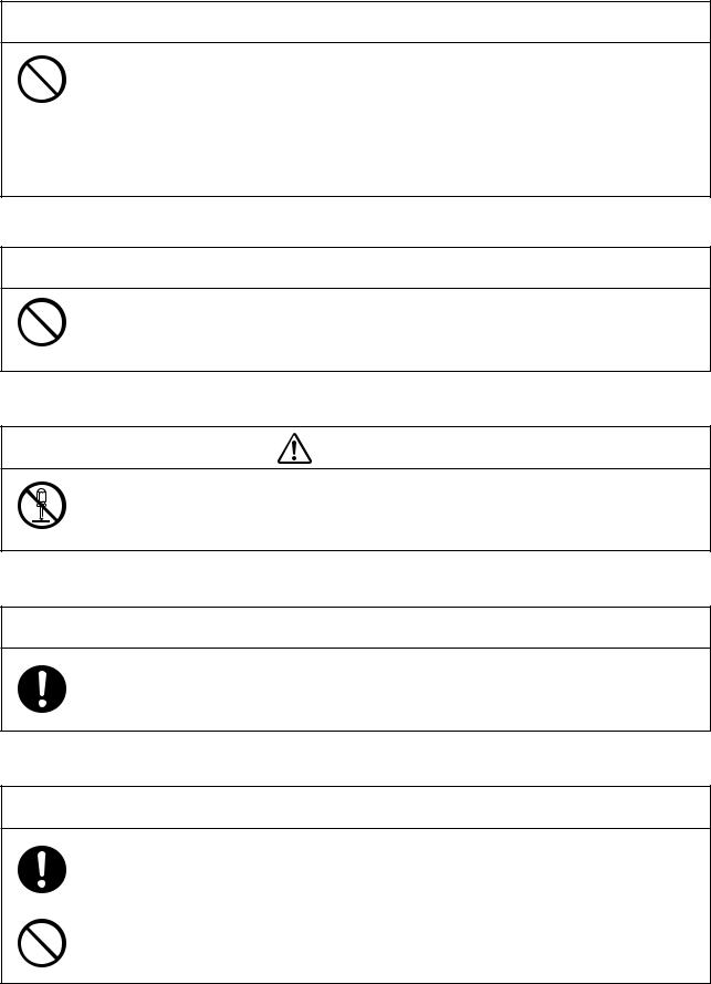
[3] Definition of Marks
1. Marks to indicate caution or warning
Mark |
Title and Indication |
General attention
Indicates unspecified general caution or warning.
Caution: Hot surface
Indicates that the surface can be dangerously hot.
2. Marks to prohibit action
Mark |
Title and Indication |
General prohibition
Indicates unspecified general prohibition.
Prohibition of disassembly
Indicates prohibition of disassembly of the unit where it may cause an electric shock or other hazards.
Prohibition of use of fire
Indicates prohibition of use of fire where an external use of fire may cause the unit to ignite under certain conditions.
3. Marks to give instructions for action
Mark |
Title and Indication |
General instruction
Indicates unspecified general action on the part of the user.
Remove the power plug from the power outlet
Instructs the user to remove the power plug from the power outlet in the case of malfunction or when thunder storm conditions threaten and lightning might occur.
Connect a ground wire
Instructs the user to connect the ground wire without fail where the unit is provided with a ground terminal.
4. Marks used on the unit
Mark |
Title and Indication |
Type BF equipment is applied here.
Caution: See the accompanying documents.
3

WARRANTIES
This equipment is guaranteed by Atom Medical Corporation for a period of one year from the date of delivery to be free of any defects in both materials and workmanship when used normally for its intended purpose. Any parts of this equipment proving to be so defective will be repaired or replaced at no charge during the warranty period. In the following cases, however, actual expenses need to be paid even during the warranty period.
1 Wear and tear of expendables.
2 Trouble and damage due to improper handling, such as dropping the unit during transport or transfer.3 Trouble and damage due to a fire, salt, gas, extraordinary voltage, earthquake, electrical storm and
flooding, or other natural calamities.
4 Travel expenses in the case of a trip to an isolated island, a remote place, etc. for the purpose of repair. Damage in shipment should be reported promptly to Atom accompanied by the certificate of the carrier concerned.
All correspondence concerning the equipment should specify the model name and the serial number.
 WARNING
Atom is by no means responsible for compensation for death, injury or damage to property if such loss should occur due to any of the following causes.
1.Trouble or damage due to installation, maintenance or repair by someone other than technical personnel belonging to, or authorized by, Atom.
2.Trouble or damage of Atom products caused by a product of another company other than that supplied by Atom.
3.Trouble or damage due to modification, maintenance or repair using a part other than that specified by Atom.
4.Trouble or damage due to neglecting the operating precautions or operating instructions described in the Operation Manual of the unit.
5.Trouble or damage due to operation under ambient conditions, including electrical requirements and installation requirements, other than those described in the Operation Manual.
6.Trouble due to carelessness or improper modification.
7.Trouble or damage due to using secondhand equipment.
8.If an accessory device which does not meet the safety requirements of this unit is used in combination with the unit, the safety level of the resulting system may be compromised. When selecting an accessory device, the following point should be taken into consideration.
Evidence that the safety of the accessory device was certified in accordance with a national standard conforming to IEC60601-1 and/or IEC60601-1-1.
4
[1] Precautions on Jamming
 WARNING
Electro-Surgical apparatus, cellular phones and other devices which generate high-frequency noise can cause jamming to various electric equipment for medical use and thus result in malfunction. Since portable phones and other devices are often used in medical facilities, some measures should be taken to prevent jamming due to such devices. Portable phones and other devices which generate high frequency should not be used near the unit during its operation to prevent malfunction of the unit due to jamming.
[2] Responsibility for Care of Equipment
 CAUTION
It is the user (a hospital, a doctor's office, a clinic) that is responsible for the operation, maintenance and care of the electric equipment for medical use. The equipment should be used only by medical personnel.
[3] Prohibition of Modification
WARNING
Do not disassemble or modify the unit. Otherwise, a fire, an electric shock or injury may result.
[4] Periodical Inspection
 CAUTION
Proper periodical inspection is needed in order to maintain and use the unit under optimum conditions.
[5] In Case of Trouble
 CAUTION
If any abnormal condition or trouble should occur to the unit, indicate on the unit that it is out of order and contact immediately your Atom distributor or service engineer. See the end of this Operation Manual for where to make contact.
If any abnormal condition or trouble should occur, do not use the unit until it has been repaired completely by a service engineer so as to prevent possible danger.
5

INTRODUCTION ...................................................................................................... |
1 |
||
[1] |
Operating Precautions |
|
|
|
1-1. |
DANGER .............................................................................................. |
8 |
|
1-2. |
WARNING ............................................................................................ |
9 |
|
1-3. |
CAUTION ........................................................................................... |
11 |
[2] |
Parts Identification |
|
|
|
2-1. Main body ................................................................................................ |
12 |
|
|
2-2. Control Panel........................................................................................... |
15 |
|
[3] |
Preparation before Use |
|
|
|
3-1. Assembly ................................................................................................. |
17 |
|
|
3-2. |
Where to Install the Infant Incubator ................................................... |
18 |
|
3-3. Locking the Casters................................................................................ |
18 |
|
|
3-5. Power Outlet and Grounding ................................................................ |
19 |
|
|
3-4. Adjusting the HL Stand (HL stand type) .............................................. |
19 |
|
|
3-6. Power Cord and Power Switch .............................................................. |
20 |
|
|
3-7. Rechargeable Battery ............................................................................. |
21 |
|
|
3-8. |
Start-up Inspection .................................................................................. |
21 |
[4] |
Incubator Air Temperature Control ..................................................... |
22 |
|
|
4-1. Setting the Incubator Air Temperature (Manual Control) ................. |
22 |
|
|
4-2. Setting the Skin Temperature (Servo Control) ................................... |
27 |
|
[5] |
Humidity Control ........................................................................................... |
32 |
|
[6] Oxygen Supply |
|
||
|
6-1. Using the Oxygen Flowmeter ............................................................... |
35 |
|
|
6-2. Using the Internal Oxygen Controller (B,C type) ............................... |
35 |
|
[7] |
Weight Monitor (C type) |
|
|
|
7-1. Calibrating the Weight Monitor ............................................................ |
39 |
|
|
7-2. Setting the Weighing Mode................................................................... |
41 |
|
|
7-3. Weighing Procedure .............................................................................. |
42 |
|
|
7-4. Recording the Weight ............................................................................ |
44 |
|
|
7-5. Correcting the Time ............................................................................... |
45 |
|
[8] |
Other Operation procedures |
|
|
|
8-1. Drawing out the Mattress Platform ...................................................... |
46 |
|
|
8-2. |
Tilting the Mattress Platform ................................................................ |
46 |
|
8-3. X-ray Cassette Tray................................................................................. |
47 |
|
|
8-4. Taking Out Cords and Tubes ................................................................ |
47 |
|
|
8-5. I/O Connector......................................................................................... |
47 |
|
|
8-6. Test Switch .............................................................................................. |
48 |
|
[9] |
Cleaning, Disinfection and Maintenance |
|
|
|
9-1. Hood ......................................................................................................... |
49 |
|
|
9-2. Mattress Platform and Parts Beneath .................................................. |
51 |
|
|
9-3. Others ...................................................................................................... |
53 |
|
|
9-4. Humidity Chamber ................................................................................. |
53 |
|
[10] Maintenance Inspection ...................................................................... |
55 |
||
|
10-1. Inspection before use ............................................................................ |
55 |
|
|
10-2. Three-month Inspection ....................................................................... |
56 |
|
|
10-3. Periodical Replacement Parts............................................................... |
57 |
|
|
10-4. Replacing the Filter ............................................................................... |
58 |
|
|
10-5. Replacing the Oxygen Sensor (Unit with oxygen controller)........... |
59 |
|
|
10-6. Inspection Check List............................................................................ |
61 |
|
|
10-7. Life........................................................................................................... |
62 |
|
|
10-8. Disposal .................................................................................................. |
62 |
|
[11] Alarms ............................................................................................................. |
63 |
||
[12] Troubleshooting ............................................................................................ |
67 |
||
[13] Technical Data............................................................................................... |
68 |
||

[1] Operating Precautions
Please follow the operating instructions described in this Manual for safe use of the unit. The unit should be operated only by those who have been trained and instructed properly in its operation. The unit should be operated only for its intended use.
1-1.  DANGER
Death or serious injury, damage to equipment or a fire will result if the instructions given below are not followed.
Be sure to close the front admittance panel and access ports when the unit is in use.
Using the unit when the front admittance panel or an access port is left open may cause the infant to fall out of the baby compartment. Be sure to close the front admittance panel and access ports even when performing phototherapy on an infant inside the incubator.
If the incubator air temperature rises when performing phototherapy, proceed with phototherapy after placing the infant in a cot or an open incubator (infant warmer), according to the doctor's judgment.
Since growing infants release a high level of heat, the incubator air temperature may rise if you place the infant in the incubator and perform phototherapy. Also, if you use multiple phototherapy units at the same time, or if the room temperature is high, the incubator air temperature may rise. In this case, proceed with phototherapy after placing the infant in a cot or an open-type incubator, according to the doctor's judgment. Take sufficient care when using a cot, as it becomes difficult to watch the infant. Also, placing an ice bag inside the incubator has the effect of decreasing the temperature. However, be sure to close the front admittance panel and access ports in this case also.
Do not leave the unit unattended when the front admittance panel or an access port is open.
If the front admittance panel or an access port is left open, the infant may fall out of the baby compartment and even lose its life. Never leave the unit unattended when the front admittance panel or an access port is open.
If the front admittance panel, a snap-open access port or a hook slider should be found loose or faulty in any way, stop using the unit immediately and ask for repair.
The infant may fall out of the incubator.
Never place a body warmer or other possible ignition sources in or near the unit.
Use of oxygen will increase a risk of explosion or a fire.
A body warmer or other devices in which fire is used or which may generate a spark may cause explosion or a fire if used near the unit.
Do not use the unit in the presence of a flammable anesthetic gas.
The unit may cause explosion or a fire if used in the presence of such a gas.
Do not use ether, alcohol or other ignitable substances.
Even a small amount of ether, alcohol or other ignitable substances may cause a fire when mixed
with the oxygen in the incubator.
8
Ground the unit securely.
Otherwise current leakage may cause an electric shock. To complete the ground connection, connect the power cord only to a 3P power outlet including a ground terminal and grounded properly. Do not operate the unit if you have any doubt about its ground connection.
Do not use near the unit any device generating high frequency.
Electro-Surgical apparatus, cellular phones and other devices which generate high frequency should not be used near the unit during its operation to prevent malfunction of the unit due to jamming.
Analyze arterial gas levels repeatedly when a high oxygen environment is required.
It is reported to be extremely important and essential, when the infant's conditions call for a high oxygen environment, to repeatedly analyze arterial gas levels in order to maintain the oxygen concentration in the incubator at a desired level. Follow the doctor's instructions in measuring the oxygen concentration because ignoring essential requirements may increase the risk of retinopathy of prematurity.
Do not jolt the unit or bump it against anything.
The screws or fixed parts may become loose.
1-2.  WARNING
Death or serious injury due to a fire or an electric shock will result if the instructions given below are not followed.
Be sure to follow the doctor's instructions in setting the incubator air temperature or the infant's skin temperature.
Be sure to follow the doctor's instructions in setting the relative humidity in the incubator.
Be sure to follow the doctor's instructions in setting the oxygen concentration in the incubator.
Oxygen for medical use should be used.
Be sure to bear in mind the following points during oxygen supply.
● Do not place a body warmer, a flashlight, oils and fats, or flammable vaporizable matters in the incubator.
●Use pure cotton for the infant's clothing and bed sheets, etc. Do not use any material that is easily charged with static electricity.
●Use pure cotton or fire-proofed materials for the clothing of doctors, nurses and those ambulance men who handle this unit.
Bear in mind the following points while using oxygen supply equipment.
● If oil, grease or a grease-like substance should get in contact with pressurized oxygen, a violent spontaneous ignition may occur. Do not let such substances stick to the oxygen pressure regulator, the oxygen cylinder valve, pipings, connections and other oxygen supply equipment.
●On a high pressure oxygen cylinder, use only a tested pressure reducing valve or pressure regulating valve indicated specifically for oxygen supply. Do not use such a valve for any gas other than air or oxygen. It is dangerous to use a valve to supply a gas other than air or oxygen and then to supply oxygen again.
9

Smoking is prohibited in the room where the unit is installed. Do not place any possible ignition sources in the room.
Avoid damaging the power cord.
A damaged power cord may cause a fire or an electric shock.
●Do not pinch the power cord between the unit and the wall, a shelf or the floor.
●Do not place the power cord near a heating apparatus or heat it.
●Do not put anything heavy on the power cord.
●Always grasp the power plug with your hand to remove the power cord from the power outlet. A damaged power cord should be replaced immediately with a new one.
Use only the power cord supplied with the unit.
Otherwise, a fire or an electric shock may result.
Before sanitizing the unit, ensure that the unit is electrically disconnected and that the unit and the heater have sufficiently cooled down.
Do not touch the power plug with a wet hand.
Touching the power plug with a wet hand may cause an electric shock.
Do not disassemble or modify the unit.
Disassembling or modifying the unit may cause a fire, an electric shock or injury.
Do not install the unit where it will be exposed to excessive humidity, dust or steam.
Installing the unit in such a place may cause a fire or an electric shock.
The power outlet should be located near the unit to prevent accidental contact with a trailing power cord. Use a separate power outlet for each unit.
Do not put many loads on one power outlet.
Connect the power cord only to a 3P power outlet in order to complete the ground connection.
Do not operate the unit if you have any doubt about its ground connection.
Ground peripheral electric equipment securely.
Never connect the unit to a power unit other than that specified.
The unit should be serviced only by qualified personnel.
Be sure to perform start-up inspection.
Using the unit without performing start-up inspection may let a defect pass unnoticed and cause a
serious accident.
10

1-3.  CAUTION
Injury or damage to surrounding objects may result if the instructions given below are not followed.
Be sure to clean and disinfect the unit before using it for the first time after purchase.
The unit is shipped without being disinfected.
Always keep the unit warm to maintain the incubator air temperature at a fixed level during the standby mode.
Place the infant in the incubator only when the incubator air temperature has stabilized.
Do not twist or pull the cords by force.
If any defect should be found, ask an expert for repair without attempting to repair it yourself.
Remove the power plug from the power outlet before moving the unit to another place or when the unit is not going to be used for a long time.
Moving the unit to another place with the power plug connected to the power outlet will damage the
power cord and may cause a fire or an electric shock.
Remove the power plug from the power outlet before cleaning or disinfecting the unit.
Cleaning or disinfecting the unit with the power plug connected to the power outlet may cause an electric shock.
Place the unit on a stable surface.
Placing the unit on an unstable platform or a tilted surface will cause it to fall or drop and may hurt someone. Check the strength of the place where the unit is to be placed or installed.
Install the unit out of reach of small children.
In performing phototherapy to the infant in the incubator, pay special attention to the infant's temperature and the incubator air temperature during the therapy.
The infant's skin temperature and the incubator air temperature may rise due to the radiant energy
of light.
Do not install the unit in direct sunshine or near a heating apparatus.
Do not expose the unit to extraordinarily high temperature or excessive humidity.
Do not place anything heavy on the unit.
Check the operation of the peripheral devices.
If a device transmitting or receiving weak signals is installed near the unit, it may be affected by the electromagnetic waves generated by the latter. Check the operation of peripheral devices for any effect before using the unit in clinical settings. Stop using the unit immediately if any trouble is detected.
11

[2] Parts Identification
2-1. Main body
■ B.C type
q
e
r


 t
t
y
u i
o

 !0 !1
!0 !1
!2
!3
!4
!5
!6

 !7
!7
!8
No. |
Name |
q |
Sensor module (B,C type) |
|
|
w |
Sensor module (A type) |
|
|
e |
Iris access port |
|
|
r |
Relay box |
|
|
t |
Test switch |
|
|
y |
MF rail |
|
|
u |
Mattress platform tilting knob |
|
|
i |
Humidity chamber cover |
|
|
o |
Front admittance panel operating knob |
No. Name
!0 Front admittance panel operating lever
!1 Front admittance panel
!2 Tube introduction slit assembly
!3 Snap-open access port
!4 Mattress
!5 Control panel
!6 Drawer
!7 Caster
!8 Elevating pedal
Note: !5Drawer (one-layer type and two-layer type) is optionally available.
12

■ A type
w
t
13
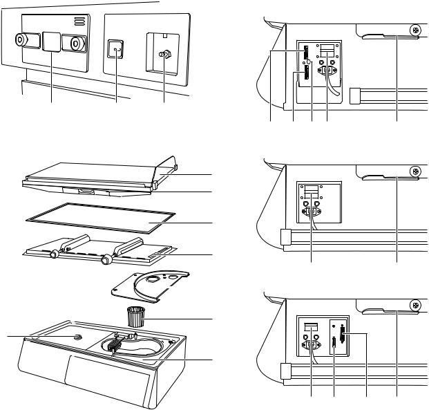
■ Rear |
|
■ Right side (Power Unit) |
|
|
● A type |
|
|
|
!9 @0 @1
#5#6#4@2 @5
■ Inside
● B type
@6
@7
@8
@9
@2 @5
|
#0 |
● C type |
|
|
#1
#3
#2
@2@3 @4 @5
No. |
|
Name |
|
No. |
|
Name |
!9 |
Filter cover |
|
|
@8 |
Top board packing |
|
@0 |
Oxygen connecting port 1 |
|
@9 |
Top board |
|
|
@1 |
Oxygen connecting port 2 (to use the inter- |
|
#0 |
Fan cover |
|
|
|
nal oxygen controller) |
|
|
|
|
|
|
|
#1 |
Fan |
|
||
@2 |
Power switch |
|
|
#2 |
Conditioning chamber |
|
@3 |
Weight monitor connector |
|
#3 |
Nozzle |
|
|
@4 |
Printer connector |
|
|
#4 |
Skin temperature connecting port |
|
@5 |
Hood stopper |
|
|
#5 |
Sensor module connector (A type) |
|
@6 |
Mattress platform |
|
|
#6 |
I/O connector (A type) |
|
@7 |
X-ray cassette tray |
|
|
|
|
|
|
|
|
|
|
|
|
Note: @7X-ray cassette tray is optinally available for A type |
|
|
|
|||
14

2-2. Control Panel |
|
|
|
|
|
|
|
|
|
|
|
#4#5 |
#6 |
@6 |
@7@81@2q w |
e |
r t |
y |
u i |
o !0 !1 |
|||
|
|
O2 |
|
1/ |
2 |
|
|
|
|
|
|
|
|
|
|
|
|
|
|
|
|
|
|
|
|
|
|
|
|
˚C |
|
|
˚C |
|
˚C |
|
g |
|
% |
% |
|
˚F |
|
|
˚F |
|
˚F |
|
|
|
|
|
|
SKIN |
37.5 37 |
AIR |
|
||
|
|
|
|
|
|
1 |
|
|
|
|
|
|
|
|
% |
% |
|
0 |
100 |
|
|
|
|
|
|
|
|
|
|
|
|
||||
|
|
O2 |
21% |
|
|
|
|
|
|
|
|
|
|
100% |
|
|
|
|
|
|
|
|
|
|
|
O2 |
|
˚C |
2 |
>37.5 |
|
1 |
|
|
|
|
|
|
˚F |
|
.>37 |
|
|
|
|
|
|
|
|
|
|
|
|
|
|
|
|
||
#7#8 #9 @9#0 #1#2#3 @3@5@4!2 !3 !4!5 !6!7!8!9@0 $0 |
$1 |
|
Temperature |
q |
High temperature alarm indicator |
|
Servo Control: Illuminates when the incubator air |
|
temperature exceeds 40 . |
|
Manual control: Illuminates when the incubator air |
|
temperature exceeds 38 (or 40 in the override |
|
mode). |
w |
Silence indicator |
|
Illuminates when an audible alarm is disabled. |
e |
Skin temperature display |
|
Displays a detected skin temperature digitally. |
r |
Servo Control indicator |
|
Illuminates when the incubator is operating in the |
|
Servo Control mode. |
t |
">37.5 " indicator |
|
Illuminates when the incubator is operating in the |
|
Servo Control override mode. |
y |
Set temperature display |
|
Servo Control: Displays a set skin temperature digi- |
|
tally. |
|
Manual Control: Displays a set incubator air tem- |
|
perature digitally. |
u |
">37 " indicator |
|
Illuminates when the incubator is operating in the |
|
Manual Control override mode. |
i |
Manual Control indicator |
|
Illuminates when the incubator is operating in the |
|
Manual Control mode. |
o |
Incubator air temperature display |
|
Displays a detected incubator air temperature digitally. |
!0 |
Power failure alarm indicator |
|
Illuminates when power supply is interrupted due to |
|
power failure, disconnected power plug or other causes. |
!1 |
System failure alarm indicator |
|
Illuminates when an abnormal condition is detected |
|
in self-diagnosis. |
!2 |
/ °F selector switch |
|
Press this switch to change the temperature display |
|
unit from to °F and vice versa. |
Temperature
!3 Skin temperature 2 switch (B,C type)
As long as this switch is pressed the skin temperature display shows skin temperature 2.
!4 Skin temperature probe alarm indicator
Servo Control: Illuminates when the skin temperature probe is faulty or not connected.
Manual Control: Illuminates when the skin temperature probe is faulty.
!5 Override switch
Press this switch while the SKIN indicator is flashing to select the override mode; the ">37.5 " indicator will flash, and the high skin temperature range of 37.6- 39.0 will be available. Press this switch while the AIR indicator is flashing to select the override mode; the ">37 " indicator will flash, and the high incubator air temperature range of 37.1-39.0 will be available.
!6 Fan alarm indicator
Illuminates when the fan is not operating or when the fan, the fan cover and the top board are not attached properly.
!7 Servo Control switch
Press this switch to operate the incubator in the Servo Control mode.
!8 Set point alarm indicator
Servo Control: Illuminates when a detected infant's skin temperature deviates from the preselected temperature by more than
± 1 .
Manual Control: Illuminates when a detected incubator air temperature deviates from the preselected temperature by more than
± 3 .
!9 Manual Control switch
Press this switch to operate the incubator in the Manual Control mode.
@0 Heater output indicator
Illuminates to indicate heater output in ten levels.
15

Humidity
@1 Relative humidity display
Displays a detected relative humidity in the incubator digitally.
@2 Set relative humidity display
Displays a set relative humidity digitally.
@3 Relative humidity selector switch
Press this switch to set a relative humidity.
When this switch is pressed, the relative humidity display will flash, and a relative humidity can be set. Select a desired setting by pressing an appropriate setting switch.
@4 Humidity chamber off alarm indicator
Illuminates when the humidity chamber is not positioned properly or humidity chamber cover is opened.
@5 Low water level alarm indicator
Flashes and illuminates when there is little water in the humidity chamber.
Oxygen Controller (B,C Type)
@6 Oxygen flow rate indicator
Indicates a detected oxygen flow rate in six levels.
@7 Oxygen concentration display
Displays a detected oxygen concentration digitally.
@8 Set oxygen concentration display
Displays a set oxygen concentration digitally.
@9 Oxygen concentration alarm indicator
Flashes when a detected oxygen concentration deviates from the preselected level by more than ± 3%.
#0 Oxygen sensor indicator
Illuminates when the oxygen sensor is faulty.
#1 Oxygen concentration selector switch
Press this switch to set an oxygen concentration. When this switch is pressed, the set oxygen concentration display will flash, and an oxygen concentration can be set.
Select a desired setting by pressing an appropriate setting switch.
#2 ON/OFF switch
Press this switch to turn the oxygen controller on/off.
#3 Calibration indicator
Flashes when O2 sensor calibration is in progress.
16
Weight Monitor (C Type)
#4 TARE SUBTRACTED indicator
Illuminates when net weight is displayed.
#5 STABILIZED indicator
Illuminates when a measured weight on the display has stabilized.
#6 Weight display
Displays a detected weight digitally.
#7 STORE switch
Press this switch to store (record) a displayed weight.
#8 ZERO switch
Press this switch to have net weight displayed.
#9 WEIGHT switch
Press this switch to weigh.
Others
$0 Setting switch
Press this switch to set temperature, relative humidity, SpO2/pulse rate alarm limits, etc. to a desired level. Every time 

 switch is pressed, a setting increases. Every time

 switch is pressed, a setting decreases.
$1 Alarm silence/reset switch
Press this switch to silence an audible alarm or to reset an alarm condition.
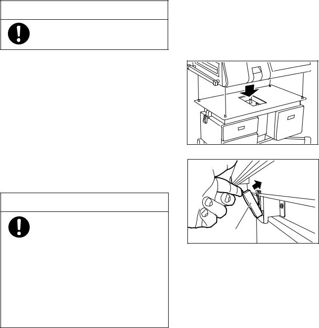
[3] Preparation before Use
3-1. Assembly
The main body of the incubator and the cabinet or the HL stand are separately packed when shipped from the factory. Assemble the separate components correctly.
 CAUTION
At least two people should join forces in assembling the unit for safety's sake.
1Place the main incubator body on the cabinet or the
HL stand in such a way that the control panel of the main body and the front surface of the cabinet or the HL stand may be positioned in the same direction. The metal fittings on the four corners of the upper surface of the cabinet or the HL stand should fit in the sockets in the bottom surface of the main body without leaving any space between them or without tilting.
2Fit in the interlocking hooks on both sides of the cabinet or the HL stand with the metallic parts on the main incubator body and lock securely.
 WARNING
Fix the main incubator body reliably to the cabinet or the HL stand by fitting in the interlocking hooks securely with the metallic parts. Otherwise the main incubator body might tip over and fall down when force is applied in opening the hood. Never move or operate the incubator before the main incubator body is fixed securely to the cabinet or the HL stand. Check that the interlocking hooks are locked in routine inspection.
Interlocking hook
17

3-2. Where to Install the Infant Incubator
Install the incubator in a horizontal place convenient for work. Avoid installing it near a heating apparatus, by the window or where an open fire is used.
 CAUTION
Avoid installing the incubator in direct sunshine, near a stove or a radiator, in the current of an air-conditioner, or by a cold window so that it may not be affected directly by such external thermal conditions.
3-3. Locking the Casters
1When the incubator is installed in a desired place, lock the two casters on the cabinet or the HL stand.
2To lock a caster, step down on the stopper tip for the stopper to be in the LOCKED position.
3To unlock a caster, place the stopper in the UN-
LOCKED position.
 CAUTION
Install the cabinet or the HL stand of the incubator on a horizontal and steady floor. Step on the two caster stoppers to lock the casters securely. To move the incubator to another place, be sure to unlock the casters.
To lock |
To unlock |
|
Step down here. |
||
Step down here. |
||
|
||
|
|
18
3-4. Adjusting the HL Stand (HL stand type)
1The height of the HL stand can be adjusted if neces- |
|
sary by stepping on an appropriate side of the elevat- |
|
ing pedal. Be sure to connect the power plug of the |
|
HL stand to the power outlet. |
|
2To raise the HL stand, step continuously on the right |
|
side( ) of the elevating pedal until a desired height |
|
is achieved. To lower it, step continuously on the |
|
left side( ) of the elevating pedal until a desired |
|
height is achieved. |
Elevating pedal |
|
 CAUTION
The operation of the elevating pedal should be limited to three minutes per hour.
3-5. Power Outlet and Grounding
 WARNING
The power outlet should be located near the unit to prevent accidental contact with a trailing power cord. Use a separate power outlet for each unit.
Do not put many loads on one power outlet.
Connect the power cord only to a 3P power outlet in order to complete the ground connec-
tion.
Do not operate the unit if you have any doubt about its ground connection.
Ground peripheral electric equipment securely.
Never connect the unit to a power unit other than that specified.
The unit should be serviced only by qualified personnel.
19
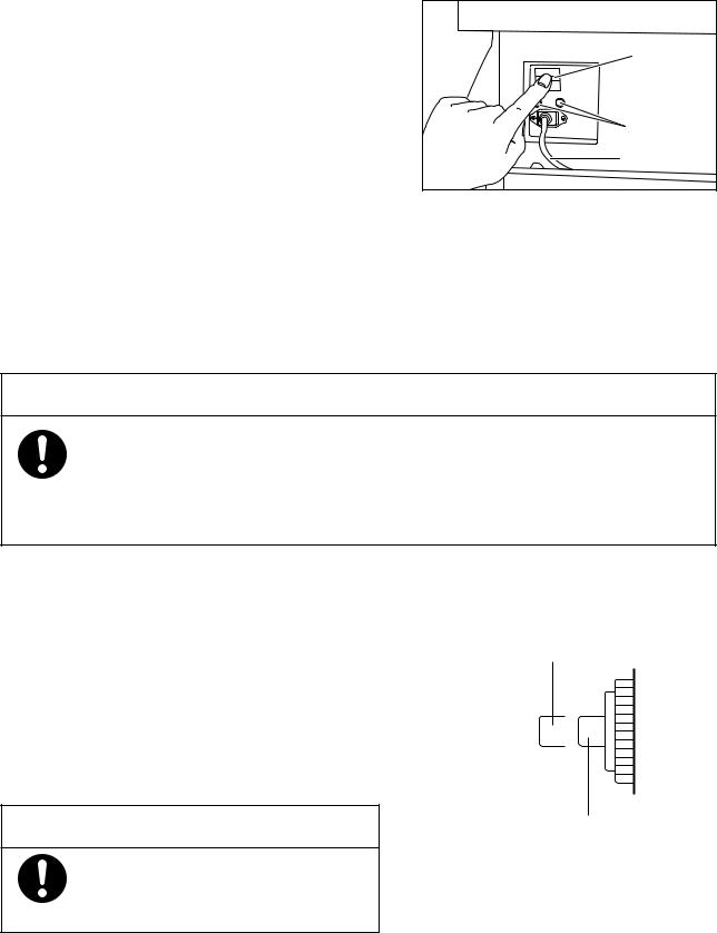
3-6. Power Cord and Power Switch
1Connect the power cord to the connector of the power unit on the side panel of the main body. Then connect the power plug on the other end of the power cord to the power outlet.
2Press the power switch to turn power on.
Power switch |
Circuit |
breaker |
Power cord |
■Memory function
If power supply should be interrupted due to power failure, disconnection of a power plug or other causes, the preselected settings excluding relative humidity and the items to be displayed will be retained in the memory, so that it is not necessary to set them anew when power returns. Thus, the last selected settings and display items will be displayed when the power switch is pressed ON.
However, since there are no memory functions for humidity control and the oxygen controller, it is necessary to operate each switch again to reset the functions after resumption of power.
 CAUTION
When the oxygen controller is working, if the power supply is interrupted due to a power failure, disconnection of the power plug or the like, the oxygen supply does not restart even if power resumes. Press the ON/OFF switch of the oxygen controller for about one second to set the oxygen controller to ON again. The oxygen concentration value which was set before the power interruption is displayed and oxygen supply resumes. Set the humidity control in the same way.
■ How to reset the circuit breaker
If an overcurrent condition should occur during the operation of the unit, the circuit breaker of the unit will be tripped to prevent possible accidents. To reset the breaker, take the following steps:
1Press the power switch to turn power off.
2Allow at least one minute after the breaker was tripped, and then depress the breaker pushbutton to reset it to the "Normal" position.
3Press the power switch to turn power on.
If the circuit breaker should be tripped again, contact your Atom distributor.
 CAUTION
To prevent a malfunction, allow at least one minute or so after the activation of the circuit breaker before pressing the pushbutton.
Tripped position
Normal position
20

3-7. Rechargeable Battery
The unit contains a rechargeable battery intended to give an alarm when the power supply has stopped. The
battery needs charging in any of the following cases:
immediately after purchasing the unit
after the activation of a mains failure alarm
after the unit has not been used for a long time
when no alarm or only a feeble alarm sounds on the activation of a mains failure alarm by setting the power switch to the ON position with the power cord off
The battery is charged automatically while the unit is connected to the wall outlet.
It takes about 50 hours for a completely discharged battery to be fully recharged.
The rechargeable battery should be replaced with a new one every four years or so.
 CAUTION
If a mains failure alarm does not sound even after recharging, contact your Atom distributor.
3-8. Start-up Inspection
Before using the unit, check it carefully for any trouble, contamination, missing parts or defective parts to make sure that it can be operated safely.
 WARNING
Be sure to perform start-up inspection. Using the unit without performing start-up inspection may let a defect pass unnoticed and cause a serious accident.
 DANGER
Always check the front admittance panel operating knobs and the hook sliders of the snap-open access ports for proper operation. If the front admittance panel or a snap-open access port should not close securely, stop using the uni and ask for repair.
21
Loading...