

Page 1
Model
Atom
\f-85
Infant
Service
Printed
in
-V03.700-
Incubator
Manual
Jan.
(mc
1995
and
se)
ATOM
3-18-15,
MEDICAL
Hongo,
CORPORATION
Bunkyo-ku,
Tokyo,
Japan.
Page 2

Page 3
The
ATOM
Model
V-85
INFANT
INCUBATOR
controls
via
microoro-
cessor
nitherro
in
the
for
patient
hes
been
that
the
Knowlecge
an
activated
the
incubator
unavailable
incubator.
safety.
operated
incubator
of
the
alarm
air
physiological
It
is
Please
properly
is
out
operating
for
a
temperature
equipped
make
before
of
order.
procedures
malfunction.
to
environment
with
various
certain
coming
In
is
provide
that
to
the
many
the
an
for
alarms
the
conclusion
cases,
cause
optimum
an
infant
designec
incubator
lack
of
mistaking
of
Page 4

Page 5
Table
of
Contents
N
WwW
PF
Specifications
Composition
Block
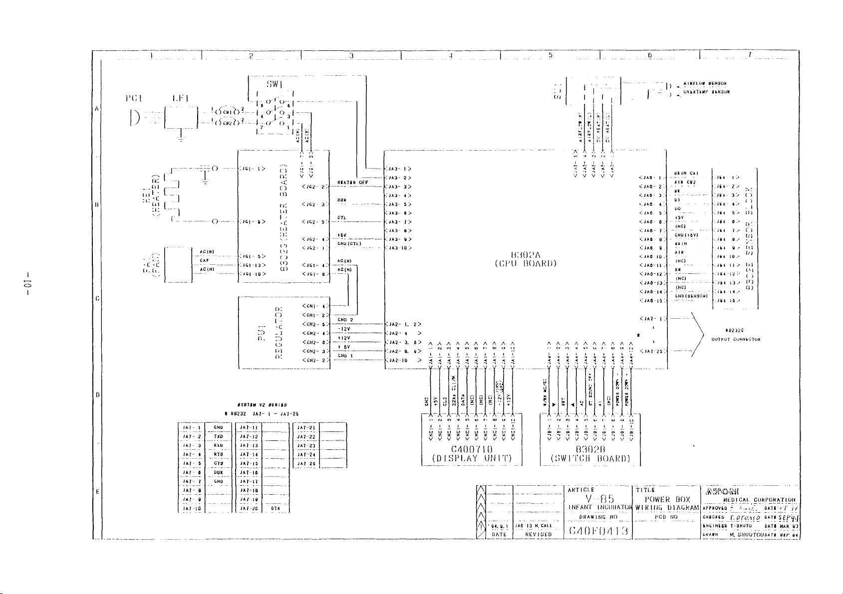
Wiring
8302A
8302B
8302G
8302D
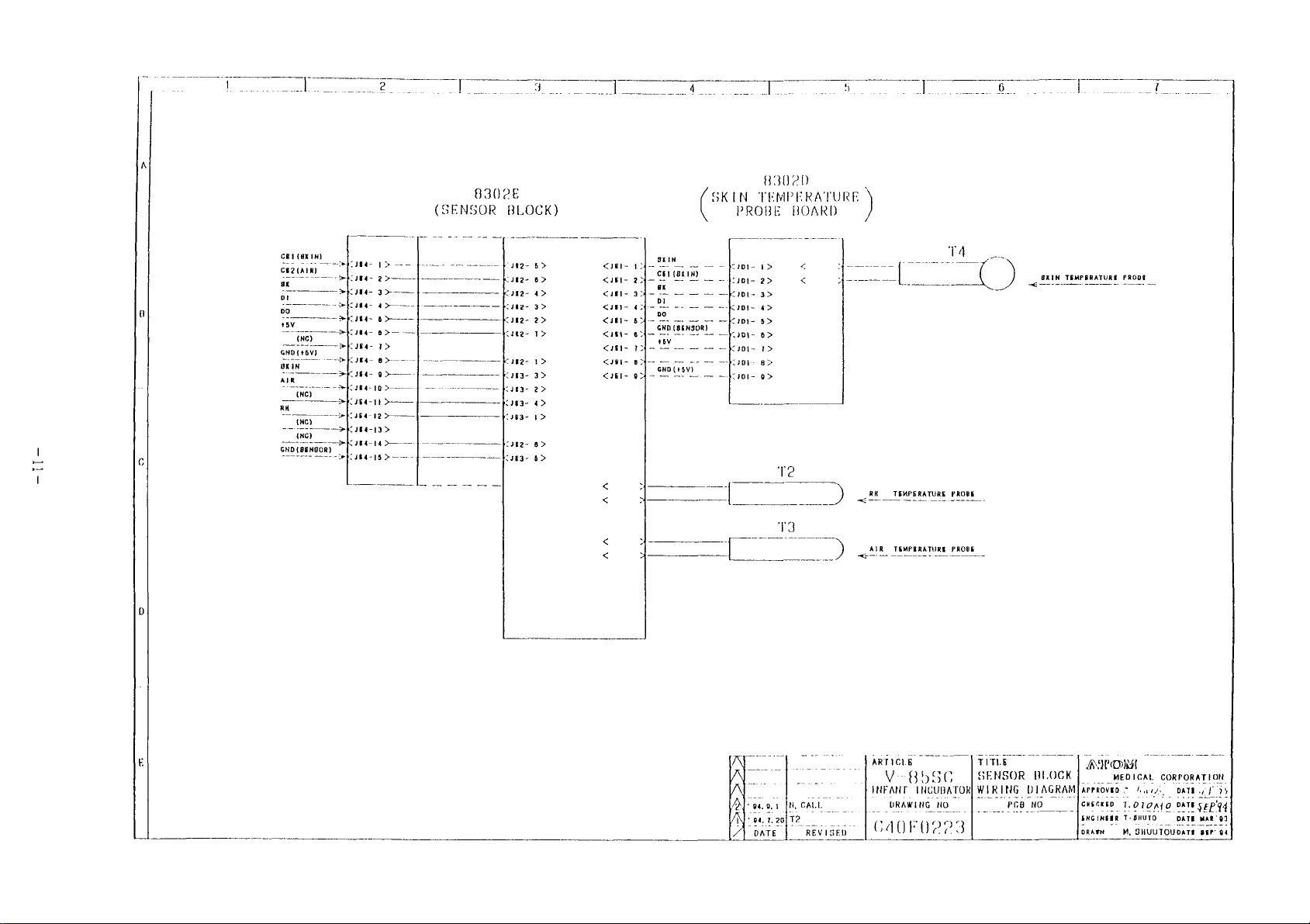
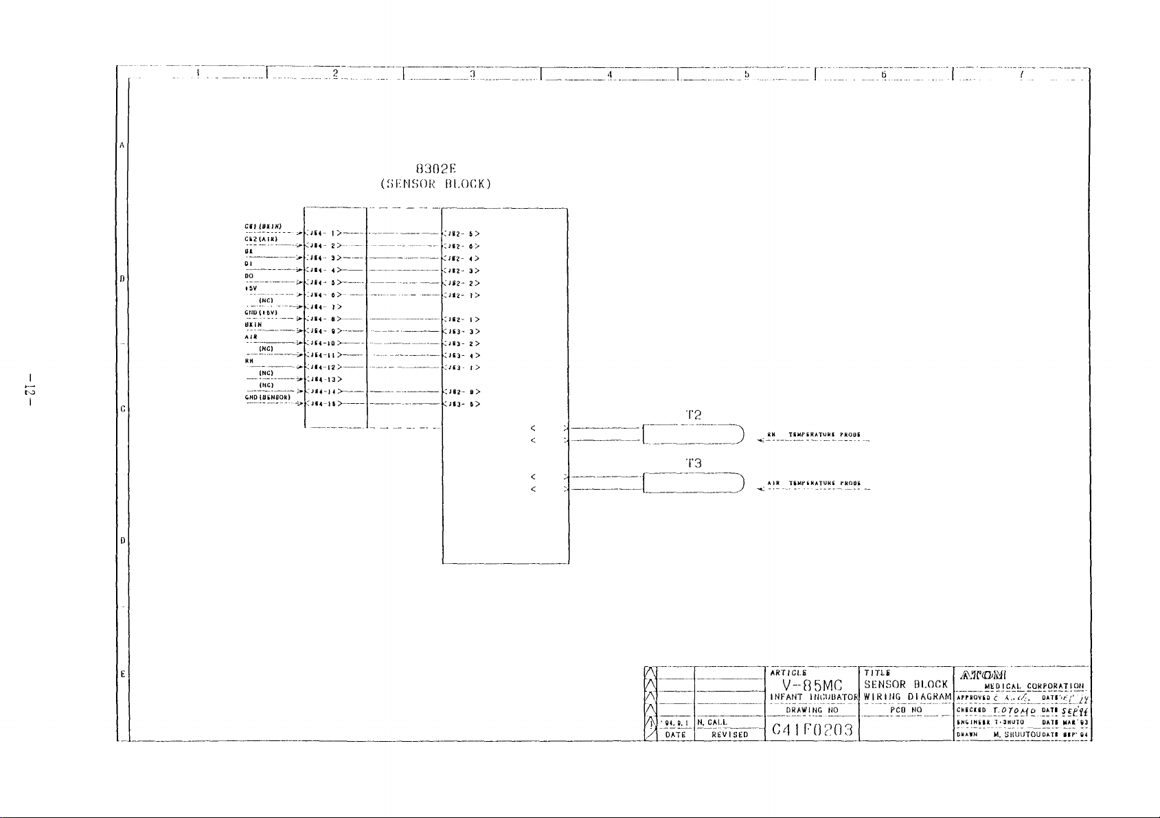
8302E
Diagram
Diagram
(CPU
(Switch
(Heater
(Skin
(Sensor
Description
Reference
Over-
A/D
temperature
converter
of
V-85
of
V-85
eee
-........
Board)
Temperature
of
voltage
Circuit
Board)
Board)
Block
Circuitry
circuit
Infant
Infant
eee
eee
Circuit
Circuit
Probe
Board)
and
circuit
detection
Incubator...............
Incubator
eee
0.0.
irene
Diagram
.................-
ee
ee
ee
eee
"tt":
Diagram
Diagram
Board)
Circuit
Function
Circuit
Diagram
Test
circuit
eee
eee
Diagram
I.........
ees
4
6
9
10
13
19
7.
6-1
7-1
7-2
Key
Display
Power
Heater
CPU
Data
O
DC+5V,
Function
Display
Sensor
input
circuit
unit
failure
output/heater
runaway
backup
412V
Test
test
test
detection/battery
current
detection
with
EEPROM
circuit
regulator
2
(Internal
Test
charge
detection
with
Display)
circuit
circuit
........
25
Page 6

Page 7

8.
Function
Test
3
(Ssecial
Internal
Test
with
Kevboard)..27
a.
10.
ll.
12.
13,
8-1
8-2
9-1
9-2
9-3
9-4
10-1
Test
Test
Function
Mode
mode
Sensor
Sensor
36.0°C
Simulation
Initialization
Initialization
Over-temperature
List
Troubleshooting............%.+
13-1
13-2
ОЕ
А1ахм$.
When
power
Immediately
Test
onen
snort
test
l
(AD/Internal
2
(Over-temperatur
4
(Test
with
test
test
test
of
Internal
Adjustment......
. +
switch
after
is
turned
self-diagnosis
circulation/Others)
Simulator).
Air
Circulation............36
06464060039
+4
< 4 4 e <
+.
+++.
4+
+++-
on
test
...............2..
<< < < <
0...
4.
++.. < 4+...
eee
34
„Al
45
14,
13-3
13-4
13-5
13-6
Over-temrerature
Internal
Incubasbor
Others
Reporting
air
of
circulation
sensor
Trouble.
alarm
alarm
............+.+
alarm
+++. + <
++...
<<
<<<.
«4+..D3
Page 8

Page 9
l.
Specifications
of
V-85
Infant
Incubator
Electrical
Skin
Skin
Skin
temperature/incubator
temperature
temperature
Incubator
Incubator
Humidity
Humidity:
Heater
Alarms:
Over-temperature
output: 0-Full,
Should
requirements:
temperature
temperature
indication:
the
displayed
setting:
indication:
setting:
indication:
Switch-selected
20-99%
indicated
alarm
Customer-specified
temperature
34.0-38.0°C
30.0-42.0°C
control
in
25.0-38.0°C
20.0-42.0°C
in
1%
steps
in
12
value
of
the
0.1°C
in
0.1°C
in
degrees
incubator
mode:
SC/MC
steps
steps
0.1°C steps
in
0.1°C
air
steps
temperature
system
exceed
temperature
indicator
and
Internal
Should
the
will
39.09C
sensor exceed
lamp
the
heater
air
circulation
any
trouble
appropriate
sound,
and
or
should
will
power
indicator
the
flash,
will
alarm
develop
heater
the
temperature
39.5+0.5°C,
an
be
disconnected.
within
lamp
power
audible
the
will
will
of
the
alarm
air
falsh,
be
the
over-
over-temperature
will
circulation
an
disconnected.
sound,
audible
system,
alarm
Page 10

Page 11
High/low
(MC
temperature
mode
of
alarm
operation)
Should
the
incubator
air
tempera-
(SC
Internal
mode
sensor
of
operation)
alarm
ture
exceed
temperature
drop
more
perature
and
Should
ture
temperature
selected
will
will
below
than
an
audible
the
deviate
flash
sound.
the
pre-selected
by
more
the
set
3°C,
indicator
temperature
the
alarm
infant's
from
by
more
and
an
than
temperature
selected
lamp
will
skin
the
than
audible
1.5°C
will
tempera-
pre-selected
t1°C,
indicator
or
by
tem-
flash
sound.
the
lamp
alarm
Should
bator
temperature
sensor
sound.
Skin
temperature
Should
the
audible
disconnected.
Power
failure
Should
Or
other
any
air
indicator
any
skin
alarm
power
trouble
temperature,
and
develop
internal
lamp will
probe
trouble develop
temperature
will
alarm
supply
causes,
sound
the
humidity,
alarm
probe
be
interrupted
power
on
any
air
circulation,
flash
on
the
indicator
and
the
failure
of
the
over-
and
an
skin
lamp
heater
due
indicator
sensors
the
internal
audible
temperature
will
power
to
will
power
lamp
for
alarm
probe,
flash,
be
failure
will
incu-
will
an
be
illuminated
and
an
audible
alarm
will
sound.
Page 12

Page 13
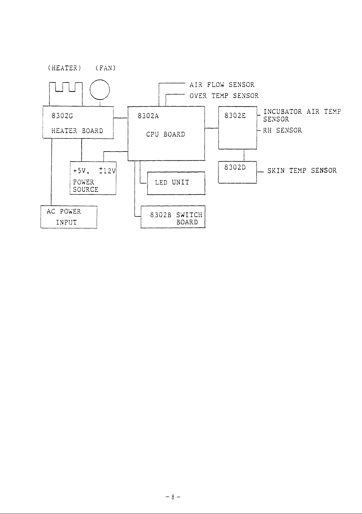
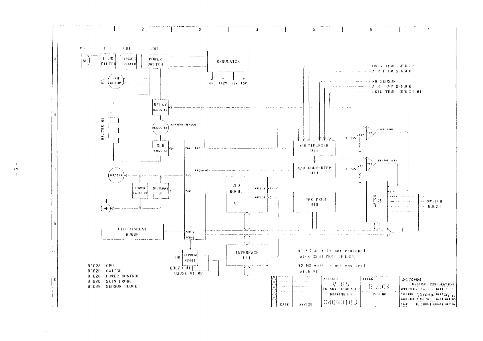
2.
Composition
of
V-85
Infant
Incubator
(temperature
control)
V-85
Infant
several
heater
to
circulation
such
2.1
features
Functions
Incubator
Detects
Relative
Detects
sensor
Incubator
temperatures,
and
or
up
six
parameters.
warm
of
air
temperature
the
air
humidity
the
is
covered
sensor
temperature
is
composed
humidity
incubator
the
P.C.
boards
sensors
temperature
with
sensor
affected
a
wet
of
air
and
air,
for
in
the
nonwoven
six
sensors
flow
for
fan
a
controlling
incubator.
by
evaporation
fabric.
to
monitor
respectively,
internal
displaying
and
heat.
a
air
The
Over-temperature
Air
Skin
Detects
using
flow
Detects
temperature
Detects
attached
an
an
sensor
changes
the
sensor
excessive
independent
in
sensor
infant's
to
the
infant's
rise
circuit.
the
skin
in
internal
temperature.
skin.
the
incubator
air
circulation.
The
air
temperature
sensor
is
Page 14

Page 15

2.2
Primary
functions
of
boards
8302A
83028
8302G
8302D
8302Е
2.3
The
main
controls.
The
switch
Operation
Equipped
current-detecting
Equipped
temperature
Equipped
temperature,
in
which
Others
board
board
and
with
with
thermistor
both
RH
sensor
equipped
equipped
with
a
power
heater
coil.
EEPROM
with
thermistors
and
calibration
in
with
with
both
failure
power
which
are
EEPROM
CPU,
with
control
data from
stored.
for
values
in
charge
switches
alarm
relay
incubator
are
LED.
and
a
skin
stored.
of
for
air
all
a
Power
Heater
Fan
LED
moto
unit
source
r
+5V
(3A),
260VA
Makes
Displays
of
V-85
the
Infant
+12V
air
circulate
various
(1.2A),
control
Incubator
-12V
in
data
(0.3A)
V-85
Infant
and
Incubator
conditions
-+
Page 16

Page 17
(HEATER)
(FAN)
8302A
CPU
一
BOARD
AIR
OVER
FLOW
TEMP
8302E
SENSOR
SENSOR
|
INCUBATOR
SENSOR
—
RH
SENSOR
AIR
TEMP
AC
POWER
INPUT
SOURCE
—|
LED
UNIT
|
Li
8302B
SWITCH
BOARD
8302D
—
SKIN TEMP
SENSOR
Page 18

Page 19
2
3
4
os
PC1
+
ーー
TAG
-
LINE
FILTER
<
u
및
sl,
i;
|
tar
D
|
000
(MO
B302A
83020
U302G
8302D
B3UPE
GPU
SWITCH
POWER
SKIN
SENSOR
(rm
MOTOR
-
τσ
]
(5
We
TT
一
LED
CHI
CIRCUITI
BREAKERI
ーーー
一
DISPLAY
8302F
CONTROL
PRODE
BLOCK
1
一
POWER
FATLURI
~
Sİ
POWER
SWI
TCH
RELAY
83026-к2|
cy
SSR
63026
ーーー
ーー
UNAWAY
~
Yi
ーー
7770
Cu
^
URRENT
BEHJOR
я
_
WI
ーーーーー
+
<]
li
e
E
PAO
Або
PA0-6 ト
—
Pan
REGULATOR
M-
GND
#12V
ー
セーーーーーーーーーー
-12V
ーー
e
CPU
00C85
"
Lor
ーーー
15V
ーーー
OVER
TEMP
SENSOR
FLOW
TEMP
TEMP
TEMI
ーー
orgR
ーーー
トー
_
ENSOR
ο
ENSOR
OS
SENSOR
KI
SWITCH
83020
AIR
-
RH
SENSOR
-
АТК
SKIN
AN
x
>
-一
PIS
ma
OVER
B
了
csmmok
~
11:
Po
so
1.
83
A
1.
6v
|
5
Me
alí
Als A .
_
-
ーー
eee
R9T8,
3
ROTTS
hi
MULTIPLEXER
一
A/D
CONVERTER
126K
ULA
|
Utd
り
-
o
ore
PROM
10
их
_
ーー
de
NM
m
3020
8
93U2E
”|
`
wa
eos
_ \ _
ermow|
x2444
41
il.
ei
ーーー
-
ーー
-一
-一
-
Ио
7
INTERFAGE
——
m
||
ーー
7%
一
-
|
|
DATE
è
with
MP
with
||
MC
unit
is
not
SKI
TEMP
MG
unit
is
not
Ul
ARTICLE
VHFANT
DRAWING
[64060103
ーー
equipped
SENSOR,
equipped
ο...
M
„K
ーー
1
TITLE
BLOCK
_
РОВ
HO
HO
ANDIM
MEDICAL
APPROVED | hu.
CHECERD
UT
SNGINEGR
ORATN
OfOAO
T,
OHUTO
M
CORPORATION
UUTOUDAT5
DATE © po
OATESCP
DATE
MAR
BEP
44
03
94
Page 20

Page 21
Page 22

Page 23
а
|.
5
-
0”
~
8302E
(SENSOR
CRY
{BX
IN)
wa
eee
一
TI
一
G
2 > 一
3> 一 一
4> 一 一 -
8
6 人 一 一 一
4
ČJ
B>———
484 9 >—
<
484-10
こす
A=
TE 一 一
“454-12 > 一 一 一
κ»
al
UA
484-158
>——
>---—-
> 一 -
>——-
pee
一-
一
A
|.
ーーーーーーーーーーーーー
ーーーーーーーーーーーー
A
——
—
A
BLOCK)
RR
$>
6»
MNR
4>
3>
2>
了
るー
a>
K3
22
RA
42
SES
nz
8>
<J83-
8>
ΣΕ
cum
<ifi-
<
>
15
(>
LŒLIES
<
<-
LH-
«1861-90 - —
ço
<
SKIN
af
EEN
32
BDÍ — —
GHD
<
SKIN
— — — = Kate
-- — Kio
(+5Y)
—-
— — — 101-
o
|
83020
TEMPERATURE
PROBE
>
dea
<4IDI-
3>
-K
401- 4 >
に
JD1-
5>
-K
401-
83
1401-
1>
BD
9>
BOARD
<
<
Το
____)
T3
OD)
Meme
ーー
PO
|
GER
TEMPERATURE
ма
талия
TA
TT
ーー
(
FRODE
OBE
) a BRIN
TEMPERATURE
PRODI
_
Aee o [UCA
시
中 了 2
REVISED
ana
У-
8550
INFANT
INCUBATOR
_
DRAWING
NO
640F0223
TR
0
SENSOR
WIRING
PCB
BLOCK
DIAGRAM
HO
pony
-MEDICAL
громко
CHECHED
ENGINGER
ORAWH
huk,
T.O10A10
T-SHUTO
M.
SHUUTOUDATI
TT
CORPORATION
DA | OS
DATE
SEPIA
DA
MAR
91
ser
qu
Page 24

Page 25
一
Cl
一
CEI
ai
-K
GND
s
{BXIN)
(BENDOR)
.
k
4
-
4
Cada
TKR
With
SITO
1084-
2464- 9 AX
5484-10
34684-11
464-123
-Jg4-13>
ES
A
(SENSOR
-一 一 一 - 一 一 一 上 53
>——-}
-
>——
|-
—
一
一
一
一
8302E
Κεν
に
A
BLOCK)
(412 - 5>
1082-
65
4>
1082-
3>
(3482-23
Jaz-
12
1862-
1>
3>
1483-
22
1JE3- 43
24637
17
1442-
8>
J8 コ - 6 >
ος
|
和
A
re
A
KU
|
T3
)
)
зи.
TEMPERATURE
AIR
TEMPERATURE
meli
i
τοσο
PROBE
|
PRODE
ee
Луче
DATE
нс.
REVISED
PARTICLE
V--85MC
INFANT
C4
INCUBATOR!
DRAWING
san
0
|
203
NO
TITLE
|SENSOR
WERING
|
PCB
BLOCK
DIAGRAM
NO
|
7
ATOM!
-—___
MEDICAL
APPROVED C Ac.
GKECAED
T.OTOA{O
ENGINGER
T'JHUTO
DRAWN
M.
SHUUTOUDATE
CORPORATION
DATO
iş
DATI
ŞEP
$$
DATE
MAR
03
Page 26

Page 27

Page 28

Page 29
в
биг.
NUTR
Ob
ove
ce
ça
ae
ro
Få
HGOiLYHOdNO9
das
am
J
nm
^
SLA
savn
8110
NOLAN
oboio:1
Sep
OLNHA-L
-Yo103w
ONE
2
|
OSAOM
M3INT
03303
asomo
ANA
VONT
6/8
OH
ORINENABOLVANONI
9d
1D
SUL
ON
GE
ONT
AYAC
adr
A
SAYAN
NAYAG
ING
90ve
DER
[Ed
agro
|
AZEL
ο
υχδ1ν
i
ns
"or
A019'0
HOHE
Tt
29
"01187
A
-Svr
ce
el
УЕ
WIY
wy
977
дуг
<<
ove
e
ce
Bare
AA
Lode
ae
6
|
р
|
E
ーー
-
ーー
1002
ANY
ZİN
-
—
——
一
一
一
一
一
-一
-一
rose
0
<
yo
Di
Lots,
sin
—-
στ
ーー
(ROT)
HERO
2
---
--
-
001
461
9001
dal
Nado
VAR
3197
nim
“rio
-
901
gal
0038
Inve
|
σσ
ーー
aj!
η”
—
Qui
$9:
газа
2070
901
081
]
rea
sup
o
a
>
=
=
eat
ana
BOT
|
,
ri
ADANI
val
004
7
4
9
‘
073
$
navd
alol
107
COV
ONS?
01007
ñ
8
ve
NO
AA
İZ
NS
cin
DIN
La
A
-
ser
pap
fay
RIVS
PL
AM
у`еа!
ーー
ーーーーーーー
ga/v
ーー
IM
νο]
sl,
İşi
slug
8%)?
ate
92
+082
Sin
Agt
ee
—
Le
ーーーー
ーーーーーーーーーーーーー-
er
ーーーーー
ーー
で
ママ
て
ぐ
く
9
8
€
"A
01-0\
avr
avr
(491)
лее
OND
λα.
d
四
1
3AO
ーーーー
(UR)
SMALL
SADO
891
-一
一
一
-一
一
从
veve
ARS
-
го
|:
ef
paf:
soy
99
|
nesse
o,
to
A01/4r01
wo
A9Z/ANL
E
ano]
^92/4*1
°*
|,
—
<<.
τόνε
σι
|
く ぐ ぐ
(2111
I
;
ぐい
ERA
[aie
Page 30

Page 31

A
|「
2
<
381-10
J81- 9 <
一
一
一
@=
」
—
3
osi
POWER
ALARM
DOWN
4
5
「
G
D
E
J31-7<
JBI- 5 <
JBI- 8 <
JB- 4 <
J81- 3 <
IBI- 2 <
JB- 1 <
|
ss
SILENCE/BESET
+
5
İsi
S
|
È
m
4
S2
sa
54
—
"A"
SET
"y"
PRESS
INCREMENT
ー
DECREMENT
FOR
-
RH
:
157
S
58
MANUAL/SERVO
>
4
X
MG
equipped
ae
Unit
is
with
not
80,
UN
IN
M
N
I\}'
94.7,
İ
|
|
|
| |
20154
DATE
|
(SC
only)
REVISED
|
ARTICLE
V-85
‚|
МРАМТ
DRAWING
С 4 0 D 7 3 | 4
INCUBATOR
NO
|
TITLE
SWITCH
|
PRINTED
|
|
|
5 3 U 2 В U 3 | DRAWN
BOARDiarrroven
PCB
NO
ATOM
[cuscKED
[ENGINEER
MEDICAL
2.
4..,..
T.OTOMO
T+SHUTO
M,
SHUUTOUWATE
CORPORATION
DATE.
7?
<<
DATE
SEP
Gd
DATE
MAR
93
SEP
94
Page 32

Page 33

A
|
|
Γη
‘Gi- 3 << 一 一
16i- 4 <
J6Gi- 5 << 一 一
一
|
po
00
0.
|
B;
」
|
|
f
|
|
|
|
164- 4 <
©
a
164- 3 <<
JG4- 2 <
J64- 1 <<e 一 一
464- 5 =
361- 1 <
ra
J61-
2
161-10 < で
261-13
233
e
т
ーーーーーーー+
<<
981
一
3,
|
|
|
|
—
a.
ーーー
X2
G2R=117PV
|
|
이
=
ㅣ
|
Li
!
一
一
y]
ce
se
To,
474F
acl!
ょ
8
а
=
aciz
74
|
2
3
CTL8-P
ri
1
1$15
i
iz
i
1
<
>
48
CM
So
NA
Fa
s
|
|
|
|
|
|
|
|
|
|
|
|
|
|
|
COOV
AREA
(C230891)
#1
62:0,
laF
¿64 1 <E
164
5
igmg
|
LI
|
1
CTLE-P
Е
V
|
V
N
|"
049.1
| |
|
|
|
[PCB
DATE
|
REVISED
ARTICLE
|
|
|
V-85
INFANT
С 4 C リ E 8 | 4 |
INCUBATOR
DRAWING
neo
NO
TITLE
HEATER
PRINTED
|
PCB
С
23
ATOM
BOARDIarrroven
NO
0 8 8
CHECKED
ENGINEER
|
DRAWN
MEDICAL
T,
XAWASAX]
M,
SHUUTOU
CORPORATION
DATE
DATE
DATE
MAR'87
DATE
SEP'
94
Page 34

Page 35

|
|
|
|
|
|
|
|
9
|
3
4
!
S
=
3:
n
G
9
|
|
|
|
|
|
|
|
SKIN
Gal
SX
01
00
+5Y
Νο
=
GEZ
73
T2
GND
J83- 3 <<
JE2- 5 <<
182- 4 <
162- 3 <<
JE2-
35
482- 1 <
ma
JEZ- 6 <<
183-2
183-
153- 5 <€
1<<
a
2<<
<<
ARA
AAA,
>>-
>>J,s1-
>>
一
一
一
一
一
-一
|
ui
X24csse | 4
<
>
| |
|
|
lina
ro
SK
i
Zo
dot
DO
련 一 -一
Cu
仁
a
FRE
me
=
a E
L
ーー
ME に る
RECO
하르
一
る
$
+
~
o
x
<
!
>:11-
>:si-
>i8l-
>:51-
>>
>
Et-
181-
+s
|
2
3
4
5
7
9
6
E
NL
N
WE
O"
94.9. 1 |R2,
N34
|
7.20iT2
DATE
|
|
01
(SC
only) | C40D7824
REVISED
(ARTICLE
V-85
INFANT
|
WOU
INCUBATORIPRINTEZ
DRAWING
|
NO
「 り ご
BMC
equipped
0
|
i
と
Unis
la
with
SENSCR
PCB
22192172
ご ご り ご どこ
not
161
ATOM
BLOCK
NO
|
し じ
ど と
|CHBCKED
|
|DRAWN
BOARDIaprroven © >
MEDICAL
BNSINBER
MM
CORPORATION
22
7,
07040
T.
8HUTO
SHUUTQUaATS
DATE = τε]
DATE
SEF
Od
|
DATS
MAR’
33
|
8sP'
24
|
Page 36

Page 37

一
<C
n
CN
m
xy
u
O
(a
тт
т
na
реа
аа
в
в
1
+
CU
1
©
1
A
-r
1
ANA
mn
上
D
+
A
—
i
A
m
1
A
©
1
ANA
x
N
x
Y
A
J
/
v
=
=-
dl
ーー
un
~
z
t-
to
mi
(q
F-
tn
t-
a:
ti
i
©
ルコ
:
ma
Y
SKİN
cd
上
[143
は
ui
n
m
0
pl
ご
=
ap
e]
EJ
ζ2
<P
ee
a
~
|
二
^
|
iO
u
CN
αν
м
on
NØ
~
i
一
1
Co
ta]
o
c
м
一
|
e
tar
--
хм
„K
1
3
n
<<
45
Y-
ta
ca
~
:
|
bota
tm
m
я
я
Page 38

Page 39

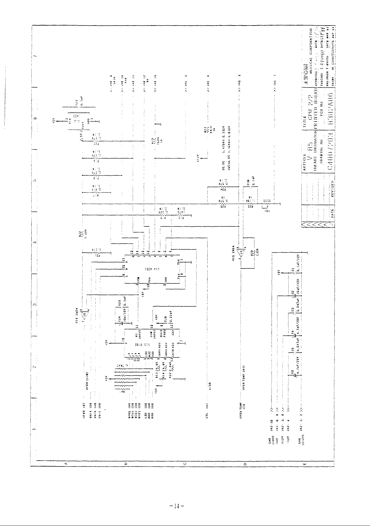
Description
6.
Circuitry
of
so
6-1
As
temperature
Reference
the
unit
2.5V+25mV
(U12,
IC
generate
reference
Output,
changes
detected
is
generated
(Test
Point)
must
very
supplied
is
pin2)
highly
voltage.
in
proportion
temperature
in
each
by
at
voltage
measure
accurately,
designed
precise
sensor,
CH0-4.
*
a...
input
©"
an
by
to
n
cH3
CH4<
to
cH
2.5V İ 25mV
ação
e
2333
mir.
+
mel
227
4420
——
meio
、
——
eis
—
ο
1x
am
UA
5
Ξ
6-2
Over-temperature
Án
over-temperature
1.
When
the
incubator
exists
and
sensor
air
activates
*
b...
virtual
If
*
the
in
divided
CHO
detection
condition
detects
temperature
the
0.15V
resistance
sensor
R17~20
by
-
4.
circuit
is
detected
the
incubator
sensor
over-tenperature
judges
+
5mV
section,
by
alr
that
(1K~
specified
R23
or
the
following
temperature
an
over-temperature
alarn.
2k.)
and
R27
at
is
voltage
two
or
inserted
fed
is
methods.
over
39.0
condition
to
C,
the
一
19
一
Page 40

Page 41

2.
The
controlled
alarn
In
when
the
The
as
shen
on
over-temperature
temperature
when
this
the
alarm
the
case,
air
temperature
both
temperature
sensor
temperature
voltage
the
the
information
over-temperature
8302G
board
detection
measurement
detects
the
audible
level.
information
to
will
go
sensor,
an
and
is
felt
obtained
CPU
via
detection
OFF and
circuit,
alarm
visual
by
the
CHS.
sensor
the
which
condition
alarms
sensor
by
the
heater
is
independent
activates
to
at
will
have
the
39.5
be
fallen
over-tenperature
becomes
output
activated,
will
of
the
CPU-
over-tenperature
+/-
0.5
C.
automatically
by
2-3°C
sensor
the
relay
be
interrupted.
is
reset
fron
sent
(K2)
©
Ref.)
415
Lis!
(Test
2904
Res
130K
The
with
for
6
;
Point)
over-temperature
VRI.
Refer
procedures.
CH5
*
2.5V
o
X7“
zLe8
#
a...
D
а
,
Less
If
inserted
to
0.
LaF
virtual
detection
ll.
Over-Temperature
35、 5 て
39020,
1.
479K0
ST
1,
308K0
resistance
in
the
0.
0.
732Y
870V
level
sensor
is
adjusted
Adjustment
sas-
2
JAS-
|
(1k-2k5)
section,
)
OVER HEAT
is
*
*
b...
cc
...
specified
R26
and
0.6
-
0.78V
Goes
conditions
high
voltage
VR1
(+5V)
is
(Point
divided
fed
to
CHS.
in
over-temperature
a<
Point
by
b).
R25,
Page 42

Page 43

6-3
A/D
converter
circuit
Temperature
over
via
The
range
De
OV
and
by
8CH
10
bit
analogue
of
disconnected,
will
be
2.5V
connection,
give
OPEN
BELA
SELB
SELC
an
187
1D6
106
106
alarm.
data
multiplexer
A/D
voltage
0.15
-
inputted.
for
short.)
while
OPEN M LOV
inputted
converter
1.15V
2.5V
CPU
by
(U14)
(U13).
inputted
in
normal
will
(In
Ul5
will
be
the
will
recognize
each
and
temperature
digitally
by a sensor
conditions.
inputted,
case
output
U15
2904
Ts
of
CH4,
OV
a
shorted
or
in
inputted
will
Should
should
OV
case
sensor
vary
it
for
disconnection
of
sensor
are
to
CPU
within
the
sensor
be
shorted,
sensor
and
switched
the
dis-
2.5V
BCD0
BCD!
BC02
BCD3
LSD
MSD
NSD
CTL
1D8
106
108
106
106
106
106
1AI
R13
Rid
R12
24,
24,
2.
7
OK
Ox
40K
C24
104/10
2°
2!
:
v
2
с
Lso
> ご
>
NSD
ZERO
ADJ
ZERO
ADI
GAIN
ADJ
625
laf
CHO
CHI
©
CH2
2
~
5
CH3
сна
CH5
Page 44

Page 45

6-7
CPU
Heater output
outputs
heater
/
heater
output
current
control
detection
circuit
Signals
KI
(SSR)
The
same
the
current
trouble
etc.
6-8
Should
the
program
an
alarm
and
the
via
developed
CPU
any
heater
U6
on
8302G
output
sensor
runaway
trouble
be in
will
be
(81C55)
board.
is
fed
(Ll)
on
detection
develop
runaway
immediately
power
will
port
back
SSR,
to
to
to
monitor
the
heater,
circuit
on
CPU
conditions,
given,
be
discon-
control?“
CPU
by
a
and
SEI,
362-2
i
JG2-1
JG2-5
——
u
000
<
a
20aA
αἱ
+5V
ts
(e
x
A
a
9TP1
oTP2
m
ISI
一
一 一 一
—
SI
'
+
一
3
a,
κ.
ミ
dE
ee
| i
CTLS-P
Li
mik
Pr
14
AC
og
nected.
(Test
ха...
# b
Point)
...
During
During
During
normal
normal
trouble
operation
operation
32Hz
+5V
OV
Page 46

Page 47

6-4
Xey
input
circuit
Wnen
bit
ADO
a
key
latch
-
7.
switch
(U4)
ΑΙ
AO
+5V,
AD
Q
Sign
Sis
31008
Spee
Tri
AS
“se
G4
Tes
一 一 CC
incorporated
will
Spot
un
023
ì
O.
nzL4
E
265
Dep;
th
05
D4
23-7
1
+
1
3
11329
Е
o
=
$
=
5
7
410
input
10
laf
the
«
=
in
key
CRE
CRT
>
+5V
1
m
83028
information
κ
一
=
board
U
JA4-
1А4-
JA4-
>
Jas-
ae
JA4-
JAd-
JA4-
is
pressed,
to
CPU
T
5
4
|
À
マー
11838
"a
er
3İ
ser
o>
8
SOFFL
>
8
OPEN
via
|
|
マヤ
DM
~
|
>
|
Y
'
2A2
8
a
AY
<
a
て
6-5
Display
Temperature
cessec
6-6
The
fo
ri
during
alarm
Power
unit
an
will
by
audible
power
supplied
is
depressed.
unit
information,
CPU
are
failure
has
an
failure.
be
given
even
though
displayed
detection
internal
alarm
and
if
the
control
Ni-Cd
LED
A
power
AC
power
on
/
display
power
status
LED
on
battery
battery
fialure
is
not
switch
and
other
the
front
charge
+5V
αἱ
2SA673
data
panel.
circuit
pro-
EB40E-32
Ci50-8V
一
99
一
Page 48

Page 49

6-9
Data
backup
with
EEPROM
When
the
correction
Note)
6-10
The
DC
on
+5V
this
As
8302D
temperature
ог
DC
unit
is
unit
values
data
board
sensor,
+5V,
is
provided
used
voltage,
is
stored
£12V
for
turned
for
(Sensor
probe
sensors
regulator
with
most
all
operation
off,
function
respective
in
each
board)
circuitry.
unit
or
DC
EEPROM
EEPROM
+5V,
sensors
board)
correspond
cannot
*12V
Should
of
the
setting
will
on
8302A
or
by
unit
8302E
to
be
PUl.
any
will
backup
be
retained.
board
board
each
replaced.
trouble
be
(CPU
instrument
affected.
and
board),
(Skin
develop
(Test
AC(L)
NC
ACCN)
Point)
—
—
—
PU
À
Regulator
4
8
2 2
10
6
—İ-
5
—
4
——
3
—
6
—+—
+12V È 0.6V
©
-12V
+5V
Gl
NC
+
+
0.15V
0.6V
Page 50

Page 51

7,
Function
Test
2
(Internal
Test
with
Display)
7-1
When
LED
Display
the
test
(Test
*
*
unit
on
ALARM
Point)
Neither
..o.
LED
test
is
the
display.
Sort
I
4
Corrige
nor LED
o
>
segment
turned
し
1
"©
Em
Check
the
Faulty
is
on,
it
>
-
É
DAF
7.9
display
AC
power
connector.
LED
unit
missing.
goes
DUN.
ロニ
ュー
こと
is
switch,
through
~
on.
a
self-diagnostic
bar
И
>
DCt12V,
i
ТИ
+5V,
=
and
+
LED
is
display
given.
2...)
>
Faulty
is
not
CPU
runaway.
corrected
again,
LED
unit.
normal,
even
total
and
a
If
the
situation
when
the
malfunction
power
unit
is
failure
is
not
is
started
suspected.
alarm
Page 52

Page 53

7-2
Sensor
test
Sensors
Operation.
(Test
* A sensor
are
* A sensor
RH
* A sensor
are
checked
Point)
alarm
all
blank.
+...)
alarm
displays
+...
alarm
for
occurs
Defective
Defective
Connector
occurs,
go
LO
or
LO
means
HI
means
occurs,
malfunction
and
LED
sensor
cable.
off.
and
incubator
HI.
sensor
short
but
circuit.
temperature
while
displays
unit.
input
line
the
unit
(temperature)
air
temperature,
disconnection;
displays
is
in
are
normal.
*
In
are
*
In
indicate
SC
all
-...3
SC
....>
>
mode,
blank.
mode,
either
Either
flow
a
sensor
probe
Connector
Defective
a
probe
LO
LO
means
Hl
means
the
over-temperature
is
alarm
is
occurs
off.
probe.
alarm
or
occurs
HI.
short;
disconnection.
disconnected
and
and
sensor
or
shorted.
temperature
temperature
or
the
displays
displays
air
一
26
一
Page 54

Page 55

8.
Function
Test
3
(Special
Internal
Test
via
Keyboard)
Special
checking
internal
Good
care
destroy
operation
the
function
air
circulation
must
the
ability
SKIN
イリ
PUG
ALARM
,
Chin
be
ルカ
ガー
TE
of
the
taken.
of
St
È
ala
keyboard
of
A/D
in
An
the
Poon Г СЕ
converter
the
V-85
accidental
incubator
SET
TEMP,
一 二 一 一 二
FUN.
Be
PO
i O SENSOR
permits
Infant
to
.
|
FULL
monitoring
and
the
Incubator.
misoperation
function.
|
Su
TT
1 © SILENCE > ©
condition
15
tt
=
PROBE
and
of
may
8-1
*
Setting
Turn
Hold
Test
display.
*
Operation
Once
switch),
through
Test
mode
others)
the
Switch
Mode
Test
a
1
power
2
until
1l
is
Mode
and
the
sequence
(A/D
switch
selected
1
is
selected,
SET
of
GOD
converter,
on
while
the
self-diagnosis
when
TEMP
display
CH.0>CH.1>CH.2>CH.3>CH.4
internal
depressing
CH.0
is
depress
will
indicated
Panel
air
Panel
program
go
<
circulation,
Switch
is
completed.
on
the
Switch
1
>CH.5->CH.6
2
(#).
SET
TEMP
(setting
Page 56

Page 57

>CH.73>0P-FA+SE
CH.0
Fa
—DH7
indicates
indicate
the
So
-H7->V1-+V2->Pd+CH.0+
the
contents
flow
of
air,
of
SE
A/D
indicates
converter,
a
defective
sensor,
the
a
programming.
Depress
appear
Vi,
(Refer
*
To
Turn
temperature
program
Panel
on
V2
and
to
stop
the
So
version,
the
Pd.
the
the
power
indicates
of
Switch
SET
TEMP
following
test
switch
a
disconnected
the
RH
and
Pd
5
(f),
display
description
procedure:
off
sensor,
indicates
and
appropriate
for
and
then
sensor,
Vl
and
the
CHO-7,0P,
for
details
on.
V2
date
data
H/
each
of
FA,
indicates
indicates
will
SE,
of
data.)
So,H7,
**
ANALYSIS
1.
Turn
on.
2.
SWl
ONY
Set
|
play
CH.0
Test
Dis-
the
LED
1
OF
power
Test.
Mode
DATA
SW5
ON
>
στ
IN
switch
1.
TEST MODE
on.
Dis-
play
590
2
Turn
*
Status
999
-99
Switch
of
...
Probe
...
Probe
2
(9)
|
skin
disconnected
shorted
SET
TEMP
temperature
CH.0
display
probe
一
28
一
Page 58

Page 59

TON,
CH.
1
ON
580
κ
Status
of
incubator
air
tenperature
— ON)
「
ON
ャ
-
ONU
Г
ом}
|
ON
fr
ONY
CH.
011.
CH.4
CH.5
CH.6
CH.7
2
3
>
ON
一
ON
>
ON
>
ON
>
ON
—
ON
<=
<
<=
<_<
=
<
580
580
645
630
120
0
sensor
999
-99
(No
*
Status
999
-99
*
Status
-99
999
*
Status
999
-99
*
Status
-99
*
A/D
...
Probe
...
Probe
meaning
of
...
Probe
...
Probe
of
...
Probe
...
Probe
of
...
Probe
...
Probe
of
...
Heater
converter
disconnected
shorted
here.)
RH
sensor
disconnected
shorted
air
flow
disconnected
shorted
over-temperature
disconnected
shorted
current
ground
sensor
sensor
output
is
sensor
zero.
>
<“
ОМ}
ON+
OP
FA
>
>
ON
ON
<
和
一
一
Г
一
Ref.)
32.2
-
an
*
Alarm
internal
set
performing
circulation.
conditions
to
be
0+1
others:
(No
meaning
Status
-19+10
over
air
normal.
initial
:
normal
defective
here.)
of
internal
(stabilized):
zero:
circulation
alarm
will
Refer
setting
conditions
occur
is
to
interface
air
circulation
normal
ㆍ
ㆍ
frequently
not
Section
of
internal
initially
10
if
for
air
Page 60

Page 61

TON
|
SE
ON
150
*
Indicates
a
defective
sensor.
TONY
1...
一
<=
So
ON
一 >
214
BIT
*
Sensor
1...
BIT
defective
7654321
sensor
skin
skin
Disconnected
7654321
temperature
disconnected
O
iene
Lover-temperature
air
flow
RH
unit
temperature
Lover-tenperature
—air
RH
off
probe
q — incubator
temperature
flow
atua!
off
air
TONY
一
ON
on
DON
H7
+
|
Ul
U2
Pd
ON
Pe
ON
ーー
ON
ーー
ON
—
skin
—
skin
365
003
700
408
*
Temperature
*
Program version
003.
*
Program
700--V03,
*
Date
v03,
version
of
programming
sensor
temperature
sensed
700
700
unit
temperature
1
(1994/8)
2
(1994/8)
by
off
probe
RH
off
sensor
(x10)
—
30
—
Page 62

Page 63

Ref.)
*
The
of
A/D
the
converter
test
simulator
values
(36.0°C)
displayed
715.
in
CH.0-3
The
test
are
those
simulator
*
The
values
stabilized
ture
* A defective
mally.
converting
Ex)
at
SE
(defective
binary
should
displayed
conditions
34.0
Conditions
Content
12°C.
or
disconnected
the
decimal
system
be
calibrated
in
of
sensor)
(10010110)
...
Skin
air
sensor
CH4
with
each
system
temp
flow
correctly.)
and
CH5
the
incubator
sensor
sensor
into
Displayed
probe
sensor,
defective.
are
is
are
the
value
off;
over-temp
obtained
air
indicated
known
binary
D = 150
in
tempera-
deci-
by
system.
Ex)
So
binary
Judging
skin
temp
no
temp
probe
skin
(disconnected
system
Content
from
sensor
off.
temp
...
the
displayed
must
sensor
sensor)
(11010110)
Skin
sensor,
sensor
be
(In
case
is
Displayed
temp
probe
air
disconnected.
values
disconnected
of
MC
attached.)
off;
flow
of
Se
nothing
value
skin temp
sensor,
and
due
is
over-temp
So,
to
wrong
D = 198
the
the
skin
as
Page 64

Page 65

A
defective
air
flow
sensor
and a defective
over-
Example
8-2
temperature
disconnected,
line
of
are
calculation
150 + 2 = 753
18 + 2 = 9...0,
1 + 2 = 0...
Put
the
beginning
10010110.
Test
Mode
2
sensor
probably
off.
...
0,
9+
fre
underlined
with
(over-temperature
the
both
figures
mean
their
75
+2
2=4...l,
together
that
the
connectors
=
37...1,
4
rightmost position,
test)
sensors
on
the
are
same
37 + 2 = 18...1,
-2
=
2...0,
one
after
and
another
you'll
get
In
this
to
39.5°C
de
я
Setting
Turn
(setting).
is
Test
incubator
test
mode,
with
the
power
completed.
Mode
2
air
the
incubator
MC.
Hold
switch
Switch
on
1
(over-temperature
temperature
while
until
setting
air
temperature
depressing
the
self-diagnosis
test)
is
reads
Panel
selected
39.5°C.
can
Switch
when
be
set
program
the
1
Page 66

Page 67

Turni
IE
o
jun.
Dum
I
7.14
=
(Test
*
Verify
incubator
Ref.)
Point)
that
Refer
air
to
an
Section
08000
over-temperature
temperature
11
for
alarm
reaches
adjustment.
is
given
39.570.5°C.
>»
when
the
Page 68

Page 69

9.
Function
Test
4
(Test
with
Simulator)
Perform
simulator.
tilted
9-1
Sensor
simulation
The
down
to
V-350
SKIN
open
of
selector
the
V-85
-V-35
AIR
Ar
È
.
test
the
Atom
ALL
short
vor
OY
control
switch
side.
Infant
ae
jab
ie
unit
on
the
incubator
„HM
52
variable
(OY
using
test
selector
Dis
ATOM"
the
simulator
V-350/V-85
should
test
be
Set
the
(Test
9-2
Set
the
(Test
the
rotary
situation
Point)
Sensor
the
rotary
situation
Point)
switch
where
*
*
*
short
switch
where
*
+
+
the
The
The
AD
converter
test
the
The
The
AD
converter
of
each
sensor
heater
value
of
each
sensor
heater
value
sensor
is
stops.
indicated
indicates
sensor
is
stops.
indicated
indicates
to
"open"
disconnected.
by
each
999
to
"short"
shorted.
by
each
-99
to
sensor
in
Test
to
sensor
in
Test Mode
simulate
(LO)
Mode
simulate
(Hl)
flashes.
l.
flashes.
l.
Page 70

Page 71

9-3
Set
36.0°C
the
rotary switch
Test
of
each
sensor
to
"36.0°C"
to
verify
that
Note)
(Test
9-4
Set
drive
the
sensor
Test
Point)
Simulation
the
rotary
to
verify
Box
*
*
switch
indicates
1
should
36.0 ? 0.2
AD
converter
test
of
the
operation
36.0°C
be
calibrated
each
È
0.2°C.
indicates
sensor
of
the
correctly.
580415
to
simulated
control
in
unit.
Test
sensor
Mode
1.
Page 72

Page 73

10.
To
the
Initialization
detect
conditions
any
of
abnormalities
of
internal
Internal
in
air
Air
Circulation
the
internal
circulation
air
circulation,
stabilized
at
the
reference
in
the
control
abnormality
air
circulation
an
alarm
Improper
abnormalities
detected
°
In
such
(Test
Point)
ambient
temperatures
unit.
develop
system,
will
occur.
initialization
in
the
properly.
a
case,
*
it
Check
value
Should
at
the
and
of
internal
is
that
shown
(30°C,
the
air
outlet
internal
internal
air
necessary
the
of
fan
motor
circulation
air
circulation
to
unit
is
internal
34°C,
or
37°C)
stop
inlet
or
of
circulation
not
re-initialize.
set
properly.
air
circulation
are
should
the
be
disturbed,
may
to
stored
internal
cause
be
If
in
any
the
10-1
Special
initial
Utmost
might
Initialization
operation
setting
care
destroy
of
should
internal
Test
-50,
it
initialize.
Mode
the
is-19
Technique
of
the
the
internal
be
taken
functioning
1
is
unit
or
above,
keyboard
as
whithin
is
set
enables
air
this
the
properly.
it
is
necessary
you
circulation
intentional
of
the
incubator.
range
However,
to
perform
system.
misoperation
of
-30
to
to
if
re-
Page 74

Page 75

al
X
Preparation
Note)
*
Preparation
of
Set
the
etc)
reservoir
the
The
setting
Should
meantime,
securely.
adjusting
unit,
of
setting
unit
with
of
any
setting
OB000
(access
water
lever
once
procedure
initial
the
set,
internal
1.
Fill
setting
2
port,
the
to a specified
to
cannot
be
mattress
humidity
high
humidification.
be
reset
circulation
done
may
on
not
the
be
platform,
level
until
system
unit
performed
and
the
in
>
set
initial
is
completed.
the
properly.
slo
~
During
Turn
2
2
Initial
when
The
from
internal
memorized.
the
(4)
until
the
initial
incubator
30
power
and
5
(4)
the
self-diagnosis
setting
SET
TEMP
setting
through
circulation
switch
on
simultaneously.
of
internal
display
air
temperature
34
to
37°C.
at
while
program
circulation
reads
each
depressing
Hold
is
F30.
changes
Stabilized
temperature
Panel
Switch
completed.
is
automatically
2
started
conditions
range
are
Switch
and
of
一
37
一
Page 76

Page 77

+
Setting
completed
Note)
Initial
wnen
The
trolled
Should
before
be
completed
said
for
accepted
initial
setting
the
SET
incubator
at
initial
setting
sure
by
the
setting.
TEMP
34°C
setting
will
and
that
control
of
internal
display
air
temperature
thereafter.
be
stopped
such
circulation
reads
will
be
interrupted,
retained.
simultaneously,
initially
unit.
Therefore,
END.
be
Should
set
is
set
and
conditions
initial
it
cannot
values
repeat
completed
con-
setting
be
have
been
Page 78

Page 79

11.
Over-temperature
Adjustment
Adjust
the
same
VRI
is
the
power
VR1
on
way
accessed
switch
the
as
over-temperature
in
8-2
Test
at
the
sensor
mounting
panel
A
PE
|
|
PE
>
Mode
connector
on
M
detection
2
(over-temperature
lock
the
side
à
©;
©
J)
a
=)
=
©
circuit
key
of
the
(6-2)
test).
section
power
in
on
unit.
*
Preparation
...
+
Preparation
...
Turn
alarm
ature
As
in
while
Switch
Test
the
incubator
of
operation
VRI
fully
may
not
rises
of
operation
8-2
Test
depressing
1
until
Mode
2
l
clockwise
be
given
to
39.5°C).
Mode
Panel
the
(over-temperature
air
temperature
when
2
2,
turn
Switch
self-diagnosis
(so
that
the
the
1
test)
setting
an
over-temperature
incubator
power
(setting),
switch
program
is
selected
reads
air
temper-
on
and
is
completed.
39.5°C.
hold
when
Page 80

Page 81

+ '
poi
tl
1
|
|
는
의
|
L
ve
ARS
SET
ゴリ
HEATER
3
一
一
一
|
OSEI
FULL
一
POINT C SENSOR O silente
с
i
LE
JU
O
SI
PROBE
3
(51
va
ii
‘
voy
000
i
i
+
|
=
ALAN
a
ブナ
7 7 7
SKIN
ルリ
LIS
Cri
'
à
カー
ーー
™
δω
τα
tem | Cakir
*
VR1
*
Verification
adjustment
When
the
39.5°C,
over-temperature
Turn
the
temperature
again
2
toward
given
is
incubator
turn
power
and
39.5°C
with
띠
VR1
switch
and
raise
to
the
air
slowly
alarm
cancel
the
verify
incubator
법
디
디디
temperature
counterclockwise
is
given.
the
that
lower
alarm.
an
air
air
over-temperature
temperature
off,
incubator
stabilizes
incubator
the
Select
temperature
>
until
Test Mode
at
at
an
air
alarm
39.5
+0.5°C.
Page 82

Page 83

LIST
OF
ALARMS
ON
V-85
INFANT
INCUBATOR
Alarn
Function
ーー
Internal | Motor
Air
Cir- | fan
culation
Over-
Tempera- | perature
o
Failure
;
ture 0.5%
Power
Alarm
し
‘uu
|
air
outlet
any
has
in
the
lation
(except
warming-up)
Incubator
|
Power
connected
plug,
cable,
of
circuit
etc.
Condition
has
stopped,
isn't
inlet
other
developed
attached,
or
blocked,
trouble
air
circu-
system
during
.
air
is
failure,
power
broken
actuation
breaker,
Delay
Within
+
15
Immedi-
ately
ately
:
air
or
with-
tem-
39.5
dis- | Immedi-
power
Heater | Flashing/
Time | output | Intermit-
tent
Off
min.
Off
- -
(Incubator
air
perature
indicator
display
figure
flashes.)
Sound
O
O
tem-
|Flashing/ | I]
|Continuous|/Continuous|
[Sound
-
- -
-
luminated
¡Sound
|
- -
O
[
Automatic
Reset Reset
Within
the
range
of
34.0
37.0°C.
一 一 一
-
[
Manual
Resetting
Cone
The
Air
tion
will
bled
minutes
it
-
15
Silence
Is
Alarm
be
disa-
for
after
reset.
an
15
y
possible,
Internal
Circula-
is
- -
min.
-
-
Page 84

Page 85

Alarm
Function
Pre-
selected
Tempera-
ture
(The
alarm
function
will
be
enabled
once
normal
range
reached.
一
2
一
An
will
more
50
over
the
range
reached,
alarm
siven
min.
nomnal
--
237°C
the
is
be
if
than
beford
is
is
)
|Alarm
Skin
|:
Sm
pera-
(ture
Incu-
ro
|?2°°F
に
tem-
pera-
ture
Condition
Skin
ture
pre-selected
temperature
[Py
1°C.
-
[Skin
|ture
pre-selected
temperature
by
1°C.
Incubator
temperature
above
selected
perature
[more
て
|1.5°c.
|Incubator
jtemperature
below
selected
perature
more
tempera-
is
more
tempera-
is
more
pre-
than
pre-
than
Incubator
perature
37.0°C.
air
is
over
above
than
below
than
air
is
tem-
by
air
is
tem-
by
3°C.
tem-
Heater
Delay
[Within
|
approx.
12
[Within
|
approx.
12
[Within
|
approx.
12
[Within
|
approx.
12
Immedi-
ately
seconds
ーー
seconds
seconds
seconds
Time
[output
off
Unchanged
off
Unchanged
Unchanged
Flashing/
Intermit-
tent
Sound
-
O)
|
(Skin~tem-
perature
indicator
display
figure
flashes.
-
(Incubator
air
tem-
perature
indicator
display
figure
flashes.)
-
|Flashing/
|Continuous
|Sound
(Skin
perature
indicator
display
figure
flashes)
-
)
(Incubator
air
temper-
ature
cator
play
flashes.
indi-
dis-
figura
-
-
[Illuminated
|/Continuous
sound
tem-
)
An
-
-
-
-
O
audible
alarm
sound
seconds
the
tor
illuminated.
will
for
when
indica-
lamp
is
[Automatic
|
Reset
O
O
O
2
O
O
|
Manual
Reset
[15
min.
Silence
-
-
-
-
-
O
O
O
O
-
Page 86

Page 87

Alarm
Function
Alarm
Condition
Delay
Heater
Time | Output
|Flashing/ {Flashing/
|
Intermit-
tent
Sound
[Continuous
{Sound
|Illuminated
|/Continuous
Sound
[Automatic
[Reset
Manual
Reset
{15
min.
Silence
Temper-
ature
Sensor
一
8
一
.
Skin
tempera-
ture
probe
Incubator
temp
Over
sensor
Air
flow
sensor
RH
sensor
Incubator
air
temp
sensor
över-tenp
sensor
Air
flow
sensor
RH
sensor
Shorted
Disconnected
nector
perly
air
sensor
temp
disconnec-
ted
[connector
is
properly
connected.
noť
is
connected.
shorted
or
not
con-
or
pro-
Immedi-
ately
Immedi-
ately
Immediately
|Inmediately
off
off
off
ー
off
-
Defečtive
sensor
play
and
Skin-tem-
perature
display
figure
indicator
flash.
dis-
figure
indi,
-
5
:
and
Defective
sensor
display
figure
indicator
flash.
'
Skin
perature
display
figure
indicator
flash
and
- -
tem-
and
-
- -
-
-
When
unit
-
When
to
-
-
the
has
returned
to
normal
conditions}.
the
unit
has
returned
Dom,
When
unit
conditions
When
unit
the
has
returned
normal
to
the
has
returned
normal
to
conditions
-
-
[
-
-
Page 88

Page 89

Alarm
Function
Heater
Discon-
nected
一
证
一
Alarm
Heater
ted,
relay
tive,
not
properly
connected,
Condition
is
disconnec- | Immediately
is
defec-
connector
etc.
is
Delay
Time
Heater | Flashing/
|
Output
off
|
Intermit-
tent
Heater
indicator
flashes.
Sound!
|Flashing/
|Continuous
Sound
-
Tlluminated | Automatic
/Continuous
sound
|Reset
—
Manual
Reset
When
unit
returned
conditions
to
the
has
normal
15
min.
Silence
Page 90

Page 91

13.
Troubleshooting
Xl
*2
13-1
When
No
operation
Power
alarm
power
failure
occurs
switch
[一
一
.
to
turned
LED
unit
(CPU,,heater,
properly,
Power
failure
人
a.
b.
AC
DC
isn't
一 一 一 一 一 一 一 一 一
Connector
Check
circuit.
power
power
OI
a.
Power
on
signal
etc.
but
no
supplied,
detection.
in
power
isn't
isn't
cord
off.
line
are
display)
一 一
一 一
power
failure
supplied.
supplied.
off.
controlled
but
一 一 一 一
unit
detection
no
is
power
一
off.
一 一 一 一
一
*3
Power
alarm
LED
abnormal
E
failure
occurs
display
-eaced
board
b.
|
a.
|
sn
Connector
*
Check
power
Regulator
in
Turn
一
power
off
power
unit
|
CPU _ Board
Power
Failure
Detection
totally.
unit
¡SW
is
then
LED
off.
on
Unit
Board
..
OK?
Page 92

Page 93

3-2
*l
*3
Immediately
LED
segment
partially
Internal
blank
sensor
after
DTF.
self-diagnosis
Defective
| |
a.
Replace
Trouble
with
LED
LED
unit
A/D
test
unit.
converter
correction
alarm,
ture
#4
Normally,
circulation
occurs
abnormal
Internal
circulation
alarm
immediately
display,
occurs
when
tempera-
air
internal
alarm
air
—>
air
flow
»
aes
circuit
Improper
|
a.
Check
b.
Replace
Faulty
circulation
Trouble
measuring
a.
Initial
circulation
sensor
|
sensor
initial
with
circuit
power
setting
internal
setting
block
block
unit
of
connection
connection
and
sensor
of
internal
circulation
internal
air
block
air
is
measured
minutes
is
turned
after
on.
5 - 10
power
b.
Replace
power
.
unit
Page 94

Page 95

13-3
*1
Over-temperature
Over-temperature
alarm
alarm
occurs
though
display
Temperature
sensor
high.
Temperature
sensor
high
La
*
Internal
incubator
hasn't
within
within
air
air
reached
of
over-temp
inlet
of
over-temp
inlet
circulation
temperature
39.0°C.
isn't
'
a.
Over-temperature
b.
Repair
is
一
>
?
or
mee
Faulty
Faulty
circuit
replace
Some
culation
trouble
over-temp
over-temp
adjustment
CPU
board
with
system
adjustment
detection
(11)
(6-2)
ee
air
cir-
in
incubator
ee
um
Note)
alarm
The
following
alarm
Following
opened
perature
and
loss.
occurs:
the
may
stabilized
for
at
heater
Thus
occur.
is
an
treatment
the
incubator
output
only
the
a.
Check
b.
Check
example
control
or
other
was
temperature
internal
setting
in
which
(a),
reasons
air
temperature
increased
of
an
an
access
to
around
air
circulation
unit.
over-temperature
port
(b).
compensate
sensor
the
The
heater
was
tem-
dropped,
for
was
(8-1)
the
Page 96

Page 97

raised
(c).
When
the
access
port
was
closed,
excessive
heat
the
heater
range,
39.5+0.5
raised
Temperature
was
and
Incubator
raised
thus
rature
the
incubator
at
an
.
air
sensor
Access
the
into
alarm
tem-
port
air
temperature
over-temperature
the
over-temperature
was
given
Temperature
the
heate
opened
(d).
around
temporarily,
sensor
detection
Temperature
the
over-tem-
と に エエ
ミミ
エイ
Reset
near
すす
で で
output
the
at
で
Page 98

Page 99

13-4
i
„L
*]
Internal
Internal
air
air
alarm
circulation
occurs
alarm
|
|
に < Alarm
immediately
turned
(Check
*
+
Point)
Is
Isn't
Are
Is
on.
occurs
fan
motor
air
incubator
humidity
after
|————)
active?
inlet
reservoir
power
or
deck,
is
outlet
hood,
properly
(>>
See
Trouble
circulation.
a.
Attached?
blocked?
etc.
14-2
.
with
Anything
internal
properly
installed?
: :
internal
to
disturb
air
circulation?
installed?
air
*3
(Check
Alarm
Point)
*
Sudden
to
occurs
air
opened
flow
access
>
disturbance
ports
might
Trouble
circulation.
a.
Isn't
culation
and
temperature
cause
with
internal
an
alarm
internal
air
disturbed?
change
(8-1).
air
cir-
due
一
49
一
Page 100

 Loading...